Memory Considerations for Low Energy Ray Tracing
13
DOI: 10.1111/cgf.12458 COMPUTER GRAPHICS forum Volume 00 (2014), number 0 pp. 1–13 Memory Considerations for Low Energy Ray Tracing D. Kopta 1 , K. Shkurko 1 , J. Spjut 1,2,3 , E. Brunvand 1 and A. Davis 1 1 School of Computing, University of Utah, Salt Lake City, UT, USA {dkopta, kshkurko, sjosef, elb, ald}@cs.utah.edu 2 NVIDIA, Santa Clara, CA, USA 3 Department of Engineering, Harvey Mudd College, Claremont, CA, USA Abstract We propose two hardware mechanisms to decrease energy consumption on massively parallel graphics processors for ray tracing. First, we use a streaming data model and configure part of the L2 cache into a ray stream memory to enable efficient data processing through ray reordering. This increases L1 hit rates and reduces off-chip memory energy substantially through better management of off-chip memory access patterns. To evaluate this model, we augment our architectural simulator with a detailed memory system simulation that includes accurate control, timing and power models for memory controllers and off-chip dynamic random-access memory . These details change the results significantly over previous simulations that used a simpler model of off-chip memory, indicating that this type of memory system simulation is important for realistic simulations that involve external memory. Secondly, we employ reconfigurable special-purpose pipelines that are constructed dynamically under program control. These pipelines use shared execution units that can be configured to support the common compute kernels that are the foundation of the ray tracing algorithm. This reduces the overhead incurred by on-chip memory and register accesses. These two synergistic features yield a ray tracing architecture that reduces energy by optimizing both on-chip and off-chip memory activity when compared to a more traditional approach. Keywords: architecture for accelerated graphics computing, hardware, graphics hardware, ray casting/tracing hardware ACM CCS: I.3.1 [Computer Graphics]: Hardware Architecture—Parallel Processing; I.3.7 [Computer Graphics]: Three- Dimensional Graphics and Realism—Raytracing 1. Introduction Ray tracing [Whi80] has traditionally been considered to require too much computation to be used in interactive rendering. With the ad- vances in integrated circuit process technologies, more computation capabilities have become available, typically in the form of increas- ingly many computation cores tiled on a chip. Ray tracing scales well with increases in available computation, but the memory sys- tem quickly becomes a bottleneck, particularly when assaulted with the random memory access patterns exhibited by naive ray tracing algorithms. Also, with the increase in available computation comes an increase in power consumption. Power is increasingly becoming a primary issue both in large high-performance chips, where power and heat are limiting how much of the chip can be active at one time [Dal13], and for chips targeting the embedded space where power is directly related to battery life and device temperature [She13]. Studying power consumption of processors under various graphi- cal workloads is becoming more popular in the research literature [CLAL07, JGDAM12, MLC06, PLS11, PLS10a, SP10, PLS10b]. Many researchers have explored ways to harness available hard- ware parallelism to enhance the speed of ray tracing. These stud- ies can be very broadly broken down into those that leverage sin- gle instruction, multiple data (SIMD) parallelism (e.g. [WSBW01, DHS04, RSH05, WBB08, BSP06, PBD*10, Ima13, Sil13]) and those that opt for a multiple instruction multiple data (MIMD) or single-program multiple-data (SPMD) approach (e.g. [GDS*08, SCS*08, SKKB09, KJJ*09, KSBD10, SKBD12, LSL*13]) or a mix of these (e.g. [WFWB13, WWB*14]). In this paper, we examine ray tracing on non-SIMD parallel hardware. We explore methods to reduce the power requirements while maintaining rendering speed and without compromising im- age quality. We assume that for the ray tracing algorithm, the arith- metic work load is already highly optimized and leaves little room c 2014 The Authors Computer Graphics Forum c 2014 The Eurographics Association and John Wiley & Sons Ltd. Published by John Wiley & Sons Ltd. 1
Transcript of Memory Considerations for Low Energy Ray Tracing

DOI: 10.1111/cgf.12458 COMPUTER GRAPHICS forumVolume 00 (2014), number 0 pp. 1–13
Memory Considerations for Low Energy Ray Tracing
D. Kopta1, K. Shkurko1, J. Spjut1,2,3, E. Brunvand1 and A. Davis1
1School of Computing, University of Utah, Salt Lake City, UT, USA{dkopta, kshkurko, sjosef, elb, ald}@cs.utah.edu
2NVIDIA, Santa Clara, CA, USA3Department of Engineering, Harvey Mudd College, Claremont, CA, USA
AbstractWe propose two hardware mechanisms to decrease energy consumption on massively parallel graphics processors for raytracing. First, we use a streaming data model and configure part of the L2 cache into a ray stream memory to enable efficientdata processing through ray reordering. This increases L1 hit rates and reduces off-chip memory energy substantially throughbetter management of off-chip memory access patterns. To evaluate this model, we augment our architectural simulator with adetailed memory system simulation that includes accurate control, timing and power models for memory controllers and off-chipdynamic random-access memory . These details change the results significantly over previous simulations that used a simplermodel of off-chip memory, indicating that this type of memory system simulation is important for realistic simulations thatinvolve external memory. Secondly, we employ reconfigurable special-purpose pipelines that are constructed dynamically underprogram control. These pipelines use shared execution units that can be configured to support the common compute kernels thatare the foundation of the ray tracing algorithm. This reduces the overhead incurred by on-chip memory and register accesses.These two synergistic features yield a ray tracing architecture that reduces energy by optimizing both on-chip and off-chipmemory activity when compared to a more traditional approach.
Keywords: architecture for accelerated graphics computing, hardware, graphics hardware, ray casting/tracing hardware
ACM CCS: I.3.1 [Computer Graphics]: Hardware Architecture—Parallel Processing; I.3.7 [Computer Graphics]: Three-Dimensional Graphics and Realism—Raytracing
1. Introduction
Ray tracing [Whi80] has traditionally been considered to require toomuch computation to be used in interactive rendering. With the ad-vances in integrated circuit process technologies, more computationcapabilities have become available, typically in the form of increas-ingly many computation cores tiled on a chip. Ray tracing scaleswell with increases in available computation, but the memory sys-tem quickly becomes a bottleneck, particularly when assaulted withthe random memory access patterns exhibited by naive ray tracingalgorithms. Also, with the increase in available computation comesan increase in power consumption. Power is increasingly becominga primary issue both in large high-performance chips, where powerand heat are limiting how much of the chip can be active at one time[Dal13], and for chips targeting the embedded space where poweris directly related to battery life and device temperature [She13].Studying power consumption of processors under various graphi-
cal workloads is becoming more popular in the research literature[CLAL07, JGDAM12, MLC06, PLS11, PLS10a, SP10, PLS10b].
Many researchers have explored ways to harness available hard-ware parallelism to enhance the speed of ray tracing. These stud-ies can be very broadly broken down into those that leverage sin-gle instruction, multiple data (SIMD) parallelism (e.g. [WSBW01,DHS04, RSH05, WBB08, BSP06, PBD*10, Ima13, Sil13]) andthose that opt for a multiple instruction multiple data (MIMD)or single-program multiple-data (SPMD) approach (e.g. [GDS*08,SCS*08, SKKB09, KJJ*09, KSBD10, SKBD12, LSL*13]) or a mixof these (e.g. [WFWB13, WWB*14]).
In this paper, we examine ray tracing on non-SIMD parallelhardware. We explore methods to reduce the power requirementswhile maintaining rendering speed and without compromising im-age quality. We assume that for the ray tracing algorithm, the arith-metic work load is already highly optimized and leaves little room
c© 2014 The AuthorsComputer Graphics Forum c© 2014 The Eurographics Association andJohn Wiley & Sons Ltd. Published by John Wiley & Sons Ltd.
1

2 D. Kopta et al. / Memory Considerations for Low Energy Ray Tracing
0
1
2
3
4
5
6
DRAM Register File L1 Instruction Cache L2 Compute (XUs)
En
erg
y / f
ram
e (J
ou
les)
5.14 (60.3%)
1.09 (12.8%) 0.92 (10.8%) 0.84 (9.8%)
0.31 (3.6%) 0.22 (2.6%)
Figure 1: Breakdown of energy consumption per frame, averagedover all test scenes in Figure 2, for our baseline architecture.
for energy reduction except at the circuit level. The primary oppor-tunity lies in improving the memory system by restructuring dataaccess patterns to increase cache hit rates and reduce off-chip mem-ory access energy. From an energy and delay perspective, this is acompelling target because fetching an operand from main memoryis both slower and three orders of magnitude more energy expen-sive than doing a floating point arithmetic operation [Dal13]. Thisis made clear by estimating the breakdown of energy consumptionper frame using our baseline architectural simulation (see Figure 1).This estimate shows that dynamic random-access memory (DRAM)energy takes up slightly over 60% of the entire energy for a framefor this system.
A natural approach would be to reduce the consumed bandwidthto main memory. This would decrease the number of main mem-ory accesses, and thus reduce the energy cost related to gatheringdata. While this is certainly true, a more detailed look at DRAMenergy costs reveals that because of the structure of DRAM cir-cuits, changing the data access patterns is an equally effectivemeans of reducing energy costs. This is true even in cases wherethe raw bandwidth consumption increases over the baseline sys-tem. This observation would not be possible without the additionof a detailed DRAM memory model to our architectural simu-lation. In this case, we use the Utah Simulated Memory Mod-ule (USIMM) DRAM memory simulator which includes a de-tailed model of the complex timing and energy behaviour of amodern DRAM memory system [CBS*12, MSC12]. The use ofthis memory simulator is a significant extension of our previoussimulations [KSS*13] and is described in Section 4. Additionalimprovements are possible by reducing register access, and in-struction fetch and decode energy by algorithmic or architecturalimprovements.
Specifically, we propose two mechanisms to improve energy per-formance for ray tracing. First, we use a streaming data modeland treelet decomposition of the acceleration structure similar to[NFLM07] and [AK10] but with specific hardware support forstream buffers to increase L1 cache hit rates and restructure theaccess patterns to the off-chip DRAM. This involves repurposingmuch of the L2 data cache as programmer-managed on-chip raybuffers with the goal of keeping ray data on-chip as much as pos-sible (Section 3.1). Scene data are organized as treelets designed to
work well both with the L1 data cache and with the internal DRAMrow buffers (historically known as DRAM pages) (Section 4).
Secondly, we employ special-purpose pipelines which are dy-namically configured under program control (Section 3.3). Thesepipelines consist of execution units (XUs), multiplexers (MUXs)and latches that are shared by multiple lightweight thread proces-sors (TPs). Our focus in this work is on the traversal and primitiveintersection phases. We do not attempt to optimize shading in thiswork, though special-purpose shading pipelines may also be effec-tive. The result is that we construct two special-purpose pipelines:one for bounding volume hierarchy (BVH) box intersection and theother for triangle intersection. The essential benefit of this tacticis to replace a large number of conventional instructions with asingle large fused box or triangle intersection instruction. This sig-nificantly reduces register and instruction memory accesses as wellas reducing the instruction decode overhead. The energy efficiencyof these pipelines is similar to an application-specific integrated cir-cuit (ASIC) design except for the relatively small energy overheadcaused by the MUXs and slightly longer wire lengths [MDP04,IPD04]. However, unlike ASICs, our pipelines are flexible sincethey are configured under program control.
These two synergistic features yield a ray tracing architecturethat significantly improves power consumption for intersection andtraversal when compared to a more traditional approach. Althoughpower is the primary metric of interest, note that this technique hasa processing overhead that can affect frame rate. Once the system’sbandwidth capability is saturated, the proposed technique alwaysoutperforms the baseline by allowing more efficient use of DRAMfor large numbers of processors.
We use 12 ray tracing benchmark scenes, as shown in Figure 2,to evaluate the performance of our proposed technique. The scenesused represent a wide range of geometric complexities and data foot-prints: architectural models (Sibenik, Crytek, Conference, Sodahall,San Miguel), scanned models (Buddha, Dragon) and nature/gamemodels (Fairy, Vegetation, Hairball). The laser scan models are un-likely to be used alone in empty space in a real situation such as amovie or game. Because of that we also include versions of themenclosed in a box, allowing rays to bounce around the environment.
2. Background
Recent work in ray tracing has explored a variety of ways to increaseefficiency. Software approaches to increase performance on exist-ing platforms involve gathering rays into packets to better matchthe SIMD execution model [BSP06, BEL*07, GPSS07, ORM08,WWB*14]. These systems can increase cache hit rates if they areable to assemble ray packets to operate on similar regions of in-terest. As an example of an SIMD approach targeted specificallyto ray tracing, the Mobile Ray Tracing Processor [KKK12], tracespacketized rays through the scene using four computation kernels,one for each step of the ray tracing algorithm. To effectively handletheir Single Instruction, Multiple Thread (SIMT) execution modelfor ray tracing, the processor is able to dynamically switch between12-way SIMT (12 processors each running the same instructionkernel on scalar data) and four-way three-vector processing (fourthreads, each using a three-vector data path) for different phases
c© 2014 The AuthorsComputer Graphics Forum c© 2014 The Eurographics Association and John Wiley & Sons Ltd.

D. Kopta et al. / Memory Considerations for Low Energy Ray Tracing 3
Sibenik Cathedral80K triangles
Fairy Forest174K triangles
Crytek Sponza262K triangles
Conference283K triangles
Dragon870K triangles
Dragon Box870K triangles
Buddha1.1M triangles
Buddha Box1.1M triangles
Vegetation1.1M triangles
Sodahall2.2M triangles
Hairball2.9M triangles
San Miguel10.5M triangles
Figure 2: Benchmark scenes used to evaluate performance.
of the algorithm. While different from the data path reconfigura-tion model we propose, it demonstrates that the different phases ofthe ray tracing algorithm can significantly benefit from hardwarepipeline customization.
More directly related to this work, there are several approachesthat attempt to reduce overall off-chip bandwidth requirementson more general architectures. These approaches can involvecache-conscious data organization [PH96, CLF*03, PKGH97,MMAM07], and ray reordering [SCL05, BWB08, NFLM07,MBK*10]. Some researchers specifically employ image-spacerather than data-space partitioning for rays [IBH11, BFH12,BIH13]. Stream-based approaches to ray generation and process-ing have also been explored both in a ray tracing context [GR08,RG09, Tsa09, AK10, NFLM07] and a volume rendering context[DK00]. At least two commercial hardware approaches to ray trac-ing use some form of ray sorting and/or classification [Ima13, Sil13].Our work has found that while an overall reduction in bandwidthconsumption is certainly helpful, it can be equally helpful to care-fully control the DRAM access patterns, even if that results in slightincreases in bandwidth consumption in some cases.
Architectural approaches for high-performance ray tracing havemostly involved the design and evaluation of non-SIMD parallel ap-proaches that are better suited to the run-time branching behaviourof ray tracing than wide SIMD processing [GDS*08, SCS*08,SKKB09, KJJ*09, KSBD10, SKBD12, LSL*13]. These efforts canbe characterized broadly as tiled lightweight general purpose coreswith relatively simple memory systems that do not support hard-ware shared memory. We use this type of parallel architecture as astarting point for our exploration.
3. Streaming Treelet Ray Tracing Architecture (STRaTA)
We start with our parallel MIMD architecture called TRaX(Threaded Ray eXecution) because it is designed specifically for
ray tracing [SKKB09], and because we also believe that the MIMDexecution model is better suited to ray tracing than the SIMD execu-tion of existing platforms [KSBP08, KSBD10, SKBD12]. We havemade this model publicly available with a cycle-accurate simulatorand LLVM-based compiler that can be modified for further architec-tural evaluation [HWR12]. Specifically, we modify this architectureusing the available tools to create STRaTA.
The basic TRaX architecture is a collection of simple, in-order,single-issue integer TPs configured with general purpose regis-ters and a small local memory. The local memory acts as an ex-tended register file for local stack operations. The exact size ofthese resources can be varied easily in our simulator. The genericTRaX thread multi-processor (TM) aggregates a number of TPswhich share more expensive XUs such as floating point and in-verse square root units. The TPs in a TM also share separatemulti-banked L1 instruction and data caches. The TM and multi-TM chip architectures are shown in Figure 3. The specifics of thesize, number and configuration of the processor resources are vari-able in the simulator. We use this infrastructure to explore howexploiting features of DRAM access patterns and access energycan lead to overall energy reduction in a parallel ray tracingarchitecture.
In short, the TRaX MIMD sharing model is the opposite of whatone finds in the SIMD structure of modern GPUs. TRaX sharesdata path XUs while allowing each TP to operate on a differentinstruction. Individual TRaX TPs do not employ branch predictionor multi-threading and thus can operate effectively with relativelysmall register files. Note, however, the total register storage on alarge chip is quite large in aggregate. Additional thread parallelismis achieved by adding more TPs, made possible by the simplicityof the TP core. The resulting small, simple TPs, can be tiled ona chip in a reasonable die area budget. Multiple TP cores form aTM block. Multiple TMs may then be aggregated onto a chip withlarger shared L2 caches. The result is a very large number of smalllightweight cores and a simple hierarchical memory system. The
c© 2014 The AuthorsComputer Graphics Forum c© 2014 The Eurographics Association and John Wiley & Sons Ltd.

4 D. Kopta et al. / Memory Considerations for Low Energy Ray Tracing
TMs TMs
L2TMs TMs
L2TMs TMs
L2TMs TMs
L2
L1D$
XUs
I$ I$TPs TPs
Figure 3: Baseline TRaX architecture. Left: an example configura-tion of a single Thread Multi-processor (TM) with 32 lightweightThread Processors (TPs) which share caches (instruction I$, anddata D$) and execution units (XUs). Right: potential TRaX chiporganization with multiple TMs sharing L2 caches [SKKB09]. In aSTRaTA configuration, the L2 caches are mostly replaced with raystream buffer memory.
throughput of TRaX is primarily limited by power and bandwidthconsumption rather than the lack of computational resources.
3.1. Ray stream buffers
Recent work [NFLM07, AK10] focuses on reducing off-chip band-width consumption by partitioning the BVH tree into subgroupscalled treelets, sized to fit comfortably in either the L1 or L2 datacache.
Each node in the BVH belongs to exactly one treelet, and treeletidentification tags are stored along with the node ID. During traver-sal, when a ray crosses a treelet boundary, it is sent to a correspond-ing ray buffer where its computation is deferred until a processor isassigned to that buffer. In this scheme, a processor will work for aprolonged period of time only on rays that traverse a single treelet.This allows that subset of BVH data to remain in the cache associ-ated with that processor to increase cache hit rate. This techniquerequires many rays to be in flight at once in order to fill the treelet raybuffers, as opposed to the typical single ray at a time per core model.The state of each ray must be stored in global memory and passedalong to other processors as needed. Ideally, this auxiliary ray statestorage should not increase off-chip bandwidth consumption drasti-cally, since reducing memory bandwidth is the end goal. In contrastto previous work, STRaTA stores the ray state in a buffer on-chip,therefore storing or retrieving rays does not affect the consumedoff-chip bandwidth.
We adapt Aila’s approach by partitioning a special-purpose raystream memory that replaces some or all of the L2 data cache. Thisavoids auxiliary traffic by never saving ray state off-chip, at the costof a lower total number of rays in flight, which are limited by thesize of the ray stream partition. The TRaX architecture uses verysimple direct-mapped caches, which prove to work well enough forthe ray tracing data access patterns [KSBD10], and save area andpower over more complex associative caches. We assign treelets tobe exactly the size of an L1 cache, and the BVH builder arrangesthe treelets into cache-aligned contiguous address spaces. Since theL1 only contains treelet data, this guarantees that while a TM is
Row 0
Row 2
Row 4
Row 6
…
Row 1
Row 3
Row 5
Row 7
…
Bank 0 Bank 1
DRAM
Figure 4: Treelets are arranged in contiguous data blocks targetedas a multiple of the DRAM row size. In this example, treelets areconstructed to be the size of two DRAM rows. Primitives are storedin a separate type of ‘treelet’ differentiated from node treelets, andsubject to the same DRAM row sizes.
working on a specific treelet, each line in the TM’s L1 cache willincur at most one miss, and will be transferred to the L1 only once.
We also modify Aila’s algorithm to differentiate triangle datafrom BVH data, and assign each to a separate type of treelet (seeFigure 4). Note that triangle treelets are not technically a ‘tree’, butsimply a collection of triangles in nearby leaf nodes. This ensuresthat any TM working on a leaf or triangle treelet is doing noth-ing but triangle intersections, allowing us to configure a specializedpipeline for triangle intersection (see Section 3.3). Similarly, whenworking on a non-leaf BVH treelet, the TM is computing only ray–box intersections utilizing a box intersection pipeline. Most impor-tantly, we differ from Aila et al.’s work by focusing our evaluationon data access patterns to the DRAM rather than simply reducingraw bandwidth consumption. DRAM chips have a complex internalstructure and correspondingly complex access protocols. Carefullycontrolling the access patterns to match the internal behaviour ofthe DRAM can have a larger impact on memory access energy thanreducing bandwidth consumption alone.
The ray stream memory holds the ray buffers for every treelet.Any given ray buffer can potentially hold anywhere from zero raysup to the maximum number that fit in the stream memory, leavingno room for any of the other buffers. The capacity of each ray bufferis thus limited by the number of rays in every other buffer. Althoughthe simulator models these dynamically sized ray buffers as a simplecollection data structure, we envision a hardware model in whichthey are implemented using a hardware managed linked-list statemachine with a pointer to the head of each buffer stored in the StaticRandom Access Memory (SRAM). Link pointers for the nodes anda free list could be stored within the SRAM as well. This wouldoccupy a small portion of the potential ray memory: not enough todrastically affect the total number of rays in flight since it requires8% or less of the total capacity for our tested configurations. Theenergy cost of an address lookup for the head of the desired raybuffer, plus the simple circuitry to handle the constant time pushand pop operations onto the end of the linked list is assumed to beroughly equal to the energy cost of the tag and bank circuitry ofthe L2 cache that it is replacing. We believe that these energy costsare roughly comparable, but this assumption will need to be moreprecisely quantified in future work.
c© 2014 The AuthorsComputer Graphics Forum c© 2014 The Eurographics Association and John Wiley & Sons Ltd.

D. Kopta et al. / Memory Considerations for Low Energy Ray Tracing 5
Note that the order in which the ray data entries in these buffersare accessed within a TM is not important. All rays in a buffer willaccess the same treelet, which will eventually be cache-resident.Rays that exit that treelet will be transferred to a different treelet’sray buffer. In this work, we employ singly linked lists which areaccessed in a last in, first out (LIFO) manner. This choice minimizeshardware overhead, allows a large number of these LIFO structuresto co-exist in a single memory block, and removes the need to keepeach structure in a contiguous address space.
Contiguous treelet data which fits in the L1 cache is also contigu-ous in the DRAM. This means that data loaded from the DRAM intothe cache can amortize the internal operations of the DRAM in away that greatly reduces both latency and energy compared to morerandom DRAM accesses. There are more details about this in Sec-tion 4 but essentially each access to DRAM loads a large amountof data (typically 4–8 KB) into a static ‘row buffer’ (historicallyknown as a DRAM page). Data accessed from a row buffer (e.g.for an L1 cache load) have a dramatically better latency and powerprofile than random DRAM accesses.
The programmer fills the ray buffers with some initial rays beforerendering begins, using provided application programming interface(API) functions to determine maximum stream memory capacity.These initial rays are all added to the buffer for the top-level treeletcontaining the root node of the BVH. After the initial rays arecreated, new rays are added to the top treelet ray buffer but only afteranother ray has finished processing, thus new rays effectively replaceold ones. When a ray completes traversal, the executing thread mayeither generate a new secondary shadow ray or global illuminationbounce ray for that path, or a new primary ray if the path is complete.Rays are removed from and added to the buffers in a one-to-one ratio,where secondary rays replace the ray that spawned them to avoidoverflowing on-chip ray buffers. Managing ray generation is doneby the programmer with the help of the API. For example, duringshading (when a ray has completed traversal/intersection), if anotherray must be generated as part of the shader, the programmer simplyadds that ray with the same pixel ID and updated state (such as raytype) to the root treelet ray buffer instead of immediately invokinga BVH traversal routine.
In this work, each ray requires 48 bytes comprised of: ray originand direction (24 bytes total), ray state (current BVH node index,closest hit, traversal state, ray type, etc. totalling 20 bytes) and atraversal stack (4 bytes, see Section 3.2).
3.2. Traversal stack
Efficient BVH traversal attempts to minimize the number of nodestraversed by finding the closest hit point as early as possible. If ahit point is known and it lies closer than the intersection with aBVH node, then the traversal can terminate early by ignoring thatbranch of the tree. To increase the chances of terminating early,most ray tracers traverse the closer BVH child first. Since it isnon-deterministic which child was visited first, typically a traver-sal stack is used to keep track of nodes that need to be visited ateach level. One can avoid a stack altogether by adding parent point-ers to the BVH, and using a deterministic traversal order (such asalways left first then right), this however eliminates the possibil-
ity of traversing the closer child first and results in less efficienttraversal.
Streaming approaches such as the one used in this work typicallyrequire additional memory space to store ray state. Rays are passedaround from core to core and are stored in memory buffers. In ourcase, the more rays present in a buffer, the longer a TM can operateon that treelet, increasing the energy savings by not accessing off-chip memory during that computation. Storing the entire traversalstack with every ray has a very large memory cost, and would reducethe total number of rays in flight significantly. There have been anumber of recent techniques to reduce or eliminate the storage sizeof a traversal stack, at the cost of extra work during traversal orextra data associated with the BVH such as parent pointers [Smi98,Lai10, HDW*11].
We use a traversal technique in which parent pointers are includedwith the BVH so full node IDs are not required for each branchdecision. We do, however, need to keep track of which direction(left child or right child) was taken first at each node. To reduce thememory cost of keeping this information, we store the direction asa single bit on a stack and thus the entire stack fits in one integer.Furthermore, there is no need for a stack pointer, as it is impliedthat the least significant bit (LSB) is the top of the stack. Stackoperations are simple bitwise integer manipulations: shift left onebit to push, shift right one bit to pop. In this scheme, after a push,either 1 is added to the stack (setting the LSB to 1, correspondingto left), or it is left alone (leaving the LSB as 0, corresponding toright). After visiting a node’s subtree, we examine the top of thestack. If the direction indicated on the top of the stack is equal towhich side the visited child was on, then we traverse the other childif necessary, otherwise we are done with both children and pop thestack and continue moving up the tree.
3.3. Reconfigurable pipelines
One of the characteristics of ray tracing is that computation can bepartitioned into distinct phases: traversal, intersection and shading.The traversal and intersection phases have a small set of specificcomputations that dominate time and energy consumption. If theavailable XUs in a TM could be connected so that data could flowdirectly through a series of XUs without fetching new instructionsfor each operation, a great deal of instruction fetch and register fileaccess energy could be saved. We propose repurposing the XUs bytemporarily reconfiguring them into a combined ray–triangle or ray–box intersection test unit using a series of latches and MUXs whenthe computation phase can make effective use of that functionality.The overhead for this reconfigurability (i.e. time, energy and area)is fairly low as the MUXs and latches are small compared to the sizeof the floating point XUs, which themselves occupy a small portionof the circuit area of a TM [MDP04, IPD04, RD07, Ram12].
Consider a hardware pipeline test for a ray intersection with anaxis-aligned box. The inputs are four 3D vectors representing thetwo corners of the bounding box, the ray origin, and ray direction(12 floats total). Although the box is stored as two points, it istreated as three pairs of planes – one for each dimension in 3D[Smi98, WBMS05]. The interval of the ray’s intersection distancebetween the near and far plane for each pair is computed, and if
c© 2014 The AuthorsComputer Graphics Forum c© 2014 The Eurographics Association and John Wiley & Sons Ltd.

6 D. Kopta et al. / Memory Considerations for Low Energy Ray Tracing
there is overlap between all three intervals, the ray hits the box,otherwise it misses. The bulk of this computation consists of sixfloating point multiplies and six floating point subtracts, followedby several comparisons to determine if the intervals overlap.
The baseline TRaX processor has eight floating point multiply,and eight floating point add/subtract units shared within a TM,which was shown to be an optimal configuration in terms of areaand utilization for simple path tracing [KSBD10]. Our ray–boxintersection pipeline uses six multipliers and six add/subtract units,leaving two of each for general purpose use. The comparison unitsare simple enough that adding extra ones as needed for the pipelineto each TM has a negligible effect on die area. The multiply andadd/subtract units have a latency of two cycles in 65 nm at 1 GHz,and the comparisons have a latency of one cycle. The box-test unitcan thus be fully pipelined with an initiation interval of one and alatency of eight cycles.
Ray–triangle intersection is typically determined based onbarycentric coordinates [MT97] and is considerably more complexthan the ray–box intersection. We remapped the computation asa data-flow graph, and investigated several potential pipeline con-figurations. Because an early stage of the computation requires ahigh-latency divide (16 cycles), all of the options have prohibitivelylong initiation intervals and result in poor utilization of XUs and lowperformance. An alternative technique uses Plucker coordinates todetermine hit/miss information [SSKN07] and requires the divideat the end of the computation, but only if an intersection occurs.If a ray intersects a triangle, we perform the divide as a separateoperation outside of the pipeline. Of the many possible ray–triangleintersection pipelines, we select one with a minimal resource re-quirement of four multipliers and two adders, which results in aninitiation interval of 18, a latency of 31 cycles and an issue width oftwo.
The final stage shades the ray without reconfiguring the TMpipeline. In our test scenes, Lambertian shading is a small portionof the total computation, and threads performing shading can takeadvantage of the leftover general purpose XUs without experiencingsevere starvation. Alternatively, if shading were more computation-ally intensive or if the data footprint of the materials is large, therays could be sent to a separate buffer or be processed by a pipelineconfigured for shading.
The programmer invokes and configures these phase-specificpipelines with simple compiler intrinsics provided in the API. Oncea TM is configured into a specific pipeline, all of the TPs withinoperate in the same mode until reconfigured. Since the pipelineshave many inputs, the programmer is also responsible for loadingthe input data (a ray and a triangle/box) into special input registersvia compiler intrinsics. This methodology keeps the instruction setsimple and avoids any long or complex instruction words.
4. Accurate DRAM Modelling
A fair amount of recent work aims to reduce off-chip bandwidthconsumption (see Section 2), since incoherent access to DRAM canbe the main performance bottleneck in a ray tracer, and is clearlya large energy consumer. Raw bandwidth consumption howeverdoes not tell the full story, since the internal structure of DRAM
yields highly variable energy and latency characteristics dependingon access patterns. A benchmark with a higher number of totalaccesses but a friendlier access pattern may outperform anotherbenchmark even if it consumes less raw bandwidth.
The internal structure of a DRAM chip is logically organizedas a set of memory arrays or banks. Each bank holds a portion ofthe total DRAM data, and can be accessed relatively independently.Because of the circuit structure of the DRAM bank arrays, theyare accessed at the granularity of an entire row of the array, whichtypically contains 4 or 8 KB of data [JNW10]. This large chunk ofdata is staged in a static buffer on the chip known as a ‘row buffer.’Because of the size of a typical row buffer, each row buffer maycontain multiple cache lines.1
A basic read from DRAM consists of two phases: reading a rowinto a row buffer (this operation is known as opening the row),then selecting and reading a column from that row. If the addressrequested lies in the row that happens to be already open, onlya column read must be performed, which is much cheaper thanopening a row, both in terms of energy and delay. This is called arow buffer hit, and amortizes the significant energy cost of openingthe row. When an address in a different row is required, the currentrow must be closed, and the new one opened. Closing a row requiresrewriting the data from the buffer back into the memory cells, sincethe initial row read is destructive. In the worst case, an access patternwill read only a single column before requiring a new row. Thememory controller can attempt to increase row buffer hit rate bypreferentially scheduling reads to open rows, but there is a limit toits effectiveness with overly chaotic access patterns.
Many architectural simulations, including previous incarnationsof our simulator [KSS*13], focus on accurate modelling of theon-chip systems, but use a simplified approximation for DRAMperformance, such as assuming an average latency and energy forall reads and writes. USIMM is a DRAM simulator with sophisti-cated modelling of timing and energy characteristics for the entireDRAM system [CBS*12], and has been used by a number of sim-ulation systems as an accurate memory model [MSC12, NCQ13].In this work, we incorporate USIMM into the TRaX simulator, andadapt it to operate with on-the-fly DRAM requests as they are gen-erated, as opposed to operating on trace files. The result is a cycleaccurate simulation of a complete GPU architecture which revealsmany performance characteristics previously hidden by a simplerDRAM model. DRAM performance is subtle and complex whenall the details are exposed. For example, detailed DRAM behaviourrequires modelling the following types of activity:
� Opening/closing rows, sometimes called a page access, and mod-elling row hits versus row misses—These can result in drasticdifferences in energy and delay.
� Scheduling (memory controller)—Reads can be serviced out oforder, which results in opportunities for increasing row hits.
� Write drain mode—Draining the write queue disables reads for along period of time, introducing hiccups in DRAM access timing.
1Historically, DRAM chips that included static memory to hold an entire rowfrom the internal memory arrays were known as ‘page mode’ DRAMs, andthe data fetched from the array on a single read were known as a DRAM page.This static buffer is known as a ‘row buffer’ in modern DRAM parlance.
c© 2014 The AuthorsComputer Graphics Forum c© 2014 The Eurographics Association and John Wiley & Sons Ltd.

D. Kopta et al. / Memory Considerations for Low Energy Ray Tracing 7
� Refresh—Memory cells must be rewritten periodically or theylose data. This disables everything for a long period of time,introducing hiccups, and consuming a large amount of energy.
� Separate memory clock—A memory controller can make deci-sions between GPU/CPU cycles.
� Queueing delay—All of the above behaviours have a combinedeffect on queueing delay.
� Background energy—DRAM energy is not only a function ofthe number and pattern of accesses, but also of running time.
� Address mapping policy—How addresses map to chan-nels/banks/rows has a direct impact on how efficiently the dataare accessed.
To understand the key difference in DRAM access patterns be-tween the baseline and STRaTA, we must examine the algorithmicsource of these accesses. The baseline ray tracer’s memory accesspattern is determined by the nature of the BVH traversal algorithm.If no special care is taken in the implementation to govern memoryaccess patterns this results in chaotic memory accesses when, forexample, path tracing inevitably generates many incoherent rays.Accesses that miss in the L1 and L2 are thus both temporally andspatially incoherent, generating continuous moderate pressure onall channels, banks and rows in DRAM.
STRaTA remaps the ray tracing algorithm to specifically targetcoherent L1 accesses. While a TM is operating on a certain treelet,all accesses will hit in the L1, except for the first to any given cacheline. Ideally, a TM will operate on the treelet for a prolonged periodof time, generating no L2 or DRAM accesses. The accesses that domake it past the L1 occur right after a TM has switched to a newtreelet. All threads within a TM will immediately begin readingcache lines for the new treelet, missing in the L1, and generating avery large burst of L2/DRAM accesses. While the small L2 cache inSTRaTA may absorb some of this burst, the remainder that makesit to DRAM will have the same bursty structure. Intuitively, thisbehaviour may seem detrimental for DRAM utilization; however,treelets are stored in a consecutive address block, mapping to as fewDRAM row buffers as possible (in our configurations treelets arethe size of two rows). Figure 4 shows an example of this. Once aDRAM row is open, the treelet data can flow quickly through thememory channel, at a very low energy cost compared to the moreconstant but incoherent accesses generated by the baseline. Table 1shows a significant increase in row buffer hit rate for STRaTA on allbenchmark scenes (Figure 2), as well as a reduction in read latencyon all but one scene.
5. Results and Discussion
We start with a baseline TRaX system (based on previousarea/performance explorations) with 128 TMs which results in 4096total TPs. Each TP is configured with 32 registers and a 512 B localmemory. Although these individual resources are small, the com-bination across all the TPs on a chip is large. Because individualTPs do not support multi-threading, we increase concurrency byadding TPs rather than increasing register file size. For the baselinenon-STRaTA system, we use a near-future capacity of 4 MB of L2cache shared among the TMs on the chip (current top-end GPUshave up to 1.5 MB of on-chip L2). In this work, each TM’s L1 data
cache (and thus maximum treelet size) is 16 KB. To model near-future GPU DRAM capabilities, we configure USIMM for both thebaseline and STRaTA to use GDDR5 with eight 64-bit channels,running at 2 GHz (8 GHz effective), for a total of 512 GB/s maxi-mum bandwidth. The chip configurations in this work use a 1 GHzcore clock rate.
All benchmark scenes (Figure 2) are rendered using a single point-light source and path tracing [Kaj86] because it generates incoherentand widely scattered secondary rays that provide a worst-case stresstest for a ray tracing architecture. We use a resolution of 1024 ×1024, and a maximum ray-bounce depth of five resulting in up to10.5 million ray segments per frame. Our focus in this work is on thetraversal and primitive intersection phases, and we do not attemptto optimize shading, so we use a simple Lambertian material on allscenes.
Our test renderer is limited to shading with non-branching raypaths. To support more advanced shaders, the programmer couldadd more information to the per-ray state to determine the remainingrays yet to be generated. When one shading ray finishes, a new raycould be generated with updated state for the associated shadingpoint. Increasing the data footprint of rays will reduce the numberof them that fit in the stream memory, but our results indicate thatthe number of rays in flight could decrease by a fair amount withoutbeing detrimental to the system. Another option is to allow the on-chip ray buffers to overflow to main memory when full (for example,[AK10] store rays in main memory), although this would likelyimpact our DRAM access patterns negatively. Note that textureaccesses could have similar DRAM access patterns if combinedinto texture ‘treelets’ (with associated ray buffers) in an augmentedSTRaTA implementation.
5.1. Off-chip memory access
Starting from our baseline configuration, we first investigate theeffects on DRAM access energy and performance by repurposingthe L2 cache as a dedicated ray stream memory. This involvesreplacing the L2 cache with a programmer-managed SRAM forstoring and retrieving treelet streams. Treelet streams consist ofrays associated with a particular BVH treelet. The size of the streammemory directly controls how many rays can be in flight at anygiven time. The STRaTA treelet-streaming model improves L1 hitrates significantly (Figure 5), but rather than remove the L2 cachecompletely we include a small 512 KB L2 cache in addition to thestream memory to absorb some of the remaining L1 misses.
Table 1 shows a breakdown of various DRAM characteristics oneach scene, as well as total running time in ms/frame, for the base-line and STRaTA techniques. Note that although STRaTA increasesL1 hit rates, the lack of a large L2 cache can result in a greaternumber of total DRAM accesses and thus bandwidth consumptionon some scenes. However, the coherent pattern of STRaTA’s ac-cesses increases the row buffer hit rate significantly on all scenes,and drastically on some (San Miguel, Buddha Box, Dragon Box).Raw bandwidth consumption, while an interesting metric, does notreveal other subtleties of DRAM access; the increase in row bufferhit rate reduces DRAM energy consumed on all but two outlier
c© 2014 The AuthorsComputer Graphics Forum c© 2014 The Eurographics Association and John Wiley & Sons Ltd.

8 D. Kopta et al. / Memory Considerations for Low Energy Ray Tracing
Table 1: DRAM performance characteristics for baseline versus STRaTA, where bold signifies the better performer. Read latency is given in units of GPUclock cycles. STRaTA DRAM energy is also shown as a percentage of baseline DRAM energy. For all columns except Row Buffer Hit Rate, lower is better.
Baseline STRaTA
DRAM Row buffer Avg. read ms/ Total DRAM DRAM Row buffer Avg. read ms/ Total DRAMScene accesses (M) hit rate (%) latency Frame energy (J) accesses (M) hit rate (%) latency Frame energy (J)
Sibenik 39 69 39 21 1.7 15 84 31 23 0.98 (58%)Fairy 22 62 49 12 1.1 14 83 45 16 0.77 (70%)Crytek 59 44 60 31 3.5 52 84 35 34 2.0 (57%)Conference 18 57 42 17 1.1 9 83 35 23 0.84 (76%)Dragon 70 55 264 22 3.2 78 80 63 25 2.5 (78%)Dragon Box 168 35 429 71 10.1 252 80 65 57 7.3 (72%)Buddha 47 63 219 13 1.9 86 77 83 23 2.7 (142%)Buddha Box 133 31 416 61 8.6 224 78 63 54 6.8 (79%)Vegetation 148 43 346 56 8.2 160 77 53 51 5.4 (66%)Sodahall 5 64 41 8 0.4 4.5 72 69 9 0.4 (100%)Hairball 135 48 352 46 6.9 126 75 62 40 4.3 (62%)San Miguel 218 27 352 108 14.8 323 60 169 94 13.7 (93%)
scenes (Buddha increases by 42% and Sodahall is tied), discussedfurther below.
As a secondary effect, increased row buffer hit rate can also leadto greatly reduced read latency, up to 85% on the Dragon Boxscene. This can result in higher performance, even though STRaTAintroduces some overhead in the traversal phase due to its lack ofa full traversal stack (Section 3.2) and the need to detect treeletboundaries.
There are two notable outlier scenes: Buddha and Sodahall. Bud-dha is the only scene in which STRaTA consumes more DRAMenergy than the baseline. The major reason for this is that Buddharequires the fewest total rays to render. The Buddha is the only ob-ject in the scene so over half of the primary rays immediately hit thebackground and do not generate secondary bounces. The few raysthat do hit the Buddha surface are likely to bounce in a directionthat will also terminate in the background. Because of this, a dis-proportionate number of rays never leave the top level (root) treelet,and Buddha does not reach a critical mass of rays required for ourray buffers to function effectively. Hence, we also consider a morerealistic scene by placing Buddha in a box.
When a TM switches to a treelet ray buffer, if there are notenough rays to keep all of its threads busy, many of the computeresources sit idle, effectively reducing parallelism. Even thoughSTRaTA increases row buffer hit rates on Buddha, the increase inDRAM energy is partly background energy caused by the nearlydoubled running time while threads sit idle. We note that DRAMenergy is not only a function of the number and pattern of accesses,but it also has a dependency on the total running time (e.g. ms/framein Table 1), mostly due to the need for continuous refreshing of theDRAM data even when no read/write activity occurs.
Also note that the baseline has a relatively high row buffer hit rateon Buddha, so STRaTA is unable to make as large of a difference.The Dragon scene is similar to Buddha, but does not exhibit thisproblem. Note that the baseline takes almost twice as long to render
Dragon than Buddha, since Dragon fills a larger portion of theframe. This closes the gap in background energy between the twotechniques. Dragon also results in more total rays, and has a smallerdata footprint with fewer unique treelets and thus more rays onaverage in each buffer.
The other interesting outlier is Sodahall. Even though it has alarge data footprint (2.2M triangles), it generates by far the fewestDRAM accesses. Most of the geometry is not visible from any oneviewing angle since it is separated into many individual rooms. Onlya small percentage of the total data is ever accessed. The pressureon DRAM is so low that background energy is the dominant factorfor both STRaTA and the baseline. The viewpoint shown (Figure 2)has similar results to viewpoints inside the building.
5.2. On-chip memory access
Figure 5 shows the on-chip memory access behaviour for a subset ofour test scenes. All other scenes except Buddha have similar results.The solid lines show the total number of L1 misses (and thus L2cache accesses), while the dotted lines show the total number ofaccesses to the stream memory for our proposed STRaTA technique.The size of the L2 cache (baseline) and stream memory (STRaTA)are the same. The significant increase in L1 hit rate allows STRaTAto do away with all but a very small L2 cache without detrimentallyincreasing DRAM accesses. More importantly, STRaTA’s DRAMaccess pattern yields a much higher row buffer hit rate.
Note in Figure 5 that the number of L1 misses for the base-line technique increases (and thus L1 hit rate decreases) as theL2 capacity and frame rate increases. While this initially seemscounter-intuitive, there is a simple explanation. The L1 cache is di-rect mapped and shared by 32 threads which leads to an increasedprobability of conflict misses. As the size of the L2 cache increases,each thread has a reduced chance of incurring a long-latency datareturn from main memory since it is more likely that the target ac-cess will be serviced by the L2 cache. The increased performance of
c© 2014 The AuthorsComputer Graphics Forum c© 2014 The Eurographics Association and John Wiley & Sons Ltd.

D. Kopta et al. / Memory Considerations for Low Energy Ray Tracing 9
0
1
2
3
4
Sib
enik
×10 8
Baseline L2 AccessesSTRaTA L2 Accesses
STRaTA Stream Accesses
0
1
2
3
4
5
Cry
tek
×10 8
0
1
2
3
4
5
6
7
Veg
etat
ion
×10 8
0
1
2
3
4
5
0.5 1 2 4 8 16
Hai
rbal
l
L2/Stream Capacity (MB)
×10 8
Figure 5: Number of L1 misses (solid lines) for the baseline, and theproposed STRaTA technique, and stream memory accesses (dashedline) on a selection of benchmark scenes. L1 hit rates range 91–94% for the baseline, and 97–99% for STRaTA. The vertical greyline corresponds to 1.5 MB, the L2 cache size of NVIDIA’s GK110GPU.
each thread generates a higher L1 access rate causing more sporadicdata access patterns. The result is an increase in the number of L1conflict misses.
The number of stream accesses is constant with regards to thesize of the stream memory because it is only a function of thenumber of treelet boundaries that an average ray must cross duringtraversal. Since the treelet size is held constant, the stream accesspatterns are only affected by which scene is being rendered. Increas-ing the stream size does however increase the average number ofrays in each treelet buffer, which allows a TM to spend more timeprocessing while the treelet’s subset of BVH data is cached in theL1.
Figure 6 shows the energy consumption per frame considering theL2 cache/stream memory accesses and off-chip memory accessesfor a subset of scenes. DRAM energy is reported by USIMM, andTable 2 shows energy estimates for the cache/stream memories from
0
1
2
3
4
Sib
enik
ener
gy /
fram
e (J
oule
s)
Baseline L2 EnergyBaseline DRAM Energy
STRaTA Stream EnergySTRaTA DRAM Energy
0
1
2
3
4
5
6
7
Cry
tek
ener
gy /
fram
e (J
oule
s)
0
2
4
6
8
10
12
14
16
Veg
etat
ion
ener
gy /
fram
e (J
oule
s)
0
2
4
6
8
10
12
0.5 1 2 4 8 16
Hai
rbal
l
ener
gy /
fram
e (J
oule
s)
L2/Stream Capacity (MB)
Figure 6: Energy consumption for the L2 cache/stream memoryand DRAM on a selection of benchmark scenes. The vertical greyline corresponds to 1.5 MB, the L2 cache size of NVIDIA’s GK110GPU.
Table 2: Estimated energy per access in nanojoules for various memories.Estimates are from Cacti 6.5.
L2/Stream memories
512 KB 1 MB 2 MB 4 MB 8 MB 16 MB0.524 0.579 0.686 0.901 1.17 1.61
Inst. Cache Reg. File
4 KB 128 B0.014 0.008
Cacti 6.5 [MBJ07]. Not surprisingly, the baseline L2 cache energyconsumption increases as larger capacities consume more energy peraccess. The proposed STRaTA technique follows a similar curve,but both techniques are dominated by DRAM energy. Note that theL1 misses (L2 accesses) for the proposed STRaTA technique inFigure 5 are to a fixed small 512 KB L2 cache. Table 1 shows thateven though STRaTA sometimes requires more DRAM accesses,
c© 2014 The AuthorsComputer Graphics Forum c© 2014 The Eurographics Association and John Wiley & Sons Ltd.
10 D. Kopta et al. / Memory Considerations for Low Energy Ray Tracing
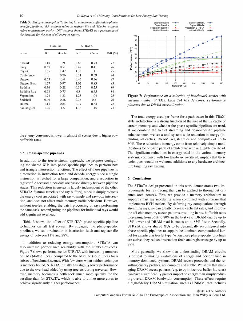
Table 3: Energy consumption (in Joules) for components affected by phase-specific pipelines. ‘RF’ column refers to register file and ‘iCache’ columnrefers to instruction cache. ‘Diff’ column shows STRaTA as a percentage ofthe baseline for the sum of all energies shown.
Baseline STRaTA
Scene RF iCache RF iCache Diff (%)
Sibenik 1.18 0.9 0.88 0.73 77Fairy 0.67 0.51 0.49 0.41 76Crytek 1.85 1.42 1.33 1.11 75Conference 1.0 0.76 0.71 0.59 74Dragon 0.53 0.4 0.45 0.36 87Dragon Box 1.27 0.97 1.02 0.83 83Buddha 0.36 0.28 0.32 0.25 89Buddha Box 0.98 0.75 0.8 0.65 84Vegetation 1.74 1.33 1.25 1.04 75Sodahall 0.49 0.38 0.36 0.3 76Hairball 1.11 0.84 0.77 0.64 72San Miguel 1.96 1.5 1.38 1.15 73
the energy consumed is lower in almost all scenes due to higher rowbuffer hit rates.
5.3. Phase-specific pipelines
In addition to the treelet-stream approach, we propose configur-ing the shared XUs into phase-specific pipelines to perform boxand triangle intersection functions. The effect of these pipelines isa reduction in instruction fetch and decode energy since a singleinstruction is fetched for a large computation, and a reduction inregister file accesses since data are passed directly between pipelinestages. This reduction in energy is largely independent of the otherSTRaTA features (treelets and ray buffers), since it simply reducesthe energy cost associated with ray–triangle and ray–box intersec-tion, and does not affect main memory traffic behaviour. However,without treelets enabling the batch processing of rays performingthe same task, reconfiguring the pipelines for individual rays wouldadd significant overhead.
Table 3 shows the effect of STRaTA’s phase-specific pipelinetechniques on all test scenes. By engaging the phase-specificpipelines, we see a reduction in instruction fetch and register fileenergy of between 11% and 28%.
In addition to reducing energy consumption, STRaTA canalso increase performance scalability with the number of cores.Figure 7 shows performance for STRaTA with increasing numbersof TMs (dotted lines), compared to the baseline (solid lines) for asubset of benchmark scenes. With few cores when neither techniqueis memory bound, STRaTA initially has slightly lower performancedue to the overhead added by using treelets during traversal. How-ever, memory becomes a bottleneck much more quickly for thebaseline than for STRaTA, which is able to utilize more cores toachieve significantly higher performance.
0
10
20
30
40
50
60
70
80
90
100
32 64 96 128 160 192 224 256 288 320
Per
form
ance
(F
PS
)
Number of TMs
Sibenik BaselineCrytek Baseline
Vegetation BaselineHairball Baseline
Sibenik STRaTACrytek STRaTA
Vegetation STRaTAHairball STRaTA
Figure 7: Performance on a selection of benchmark scenes withvarying number of TMs. Each TM has 32 cores. Performanceplateaus due to DRAM overutilization.
The total energy used per frame for a path tracer in this TRaX-style architecture is a strong function of the size of the L2 cache orstream memory, and whether the phase-specific pipelines are used.If we combine the treelet streaming and phase-specific pipelineenhancements, we see a total system-wide reduction in energy (in-cluding all caches, DRAM, register files and compute) of up to30%. These reductions in energy come from relatively simple mod-ifications to the basic parallel architecture with negligible overhead.The significant reductions in energy used in the various memorysystems, combined with low hardware overhead, implies that thesetechniques would be welcome additions to any hardware architec-ture targeting ray tracing.
6. Conclusions
The STRaTA design presented in this work demonstrates two im-provements for ray tracing that can be applied to throughput ori-ented architectures. First, we provide a memory architecture tosupport smart ray reordering when combined with software thatimplements BVH treelets. By deferring ray computations throughstreaming rays, we can greatly increase cache hit rates, and improvethe off-chip memory access patterns, resulting in row buffer hit ratesincreasing from 35% to 80% in the best case, DRAM energy up to43% lower and DRAM read latencies up to 85% faster. Secondly,STRaTA allows shared XUs to be dynamically reconfigured intophase-specific pipelines to support the dominant computational ker-nel for a particular treelet type. When these phase-specific pipelinesare active, they reduce instruction fetch and register usage by up to28%.
More generally, we show that understanding DRAM circuitsis critical to making evaluations of energy and performance inmemory-dominated systems. DRAM access protocols, and the re-sulting energy profiles, are complex and subtle. We show that man-aging DRAM access patterns (e.g. to optimize row buffer hit rates)can have a significantly greater impact on energy than simply reduc-ing overall DRAM bandwidth consumption. These effects requirea high-fidelity DRAM simulation, such as USIMM, that includes
c© 2014 The AuthorsComputer Graphics Forum c© 2014 The Eurographics Association and John Wiley & Sons Ltd.
D. Kopta et al. / Memory Considerations for Low Energy Ray Tracing 11
internal DRAM access modelling, and detailed modelling of thememory controller. The interaction between compute architecturesand DRAM to reduce energy is an underexplored area. We plan tocontinue to explore how applications like ray tracing interact withthe memory system. Especially interesting is the DRAM subsys-tem because DRAM access is the primary consumer of energy ina memory-constrained application such as ray tracing, or graphicsrendering in general. In particular, one might develop a memory con-troller scheduler that is ray-tracing aware, and hide DRAM accessoptimizations from the programmer.
Acknowledgements
This material is based upon work supported by the National ScienceFoundation under Grant No. CNS-1017457. Manjunath Shevgoor,Niladrish Chatterjee and Tim Purcell provided many useful discus-sions. Sibenik Cathedral is from Marko Dabrovic, Fairy Forest isfrom the University of Utah, Crytek Sponza is from Frank Meinlat Crytek and Marko Dabrovic, Conference is from Anat Grynbergand Greg Ward, Dragon and Buddha are from the Stanford Com-puter Graphics Laboratory, Vegetation and Hairball are from SamuliLaine and San Miguel is from Guillermo Leal Laguno.
References
[AK10] AILA T., KARRAS T.: Architecture considerations for tracingincoherent rays. In Proceedings of High Performance Graphics(Saarbrucken, Germany, 2010).
[BEL*07] BOULOS S., EDWARDS D., LACEWELL J. D., KNISS J., KAUTZ
J., SHIRLEY P., WALD I.: Packet-based whitted and distribution raytracing. In Proceedings of Graphics Interface (Montreal, Quebec,Canada, 2007).
[BFH12] BROWNLEE C., FOGAL T., HANSEN C. D.: GLuRay: Enhancedray tracing in existing scientific visualization applications usingOpenGL interception. In Proceedings of EGPGV (Cagliari, Italy,2012), Eurographics, pp. 41–50.
[BIH13] BROWNLEE C., IZE T., HANSEN C. D.: Image-parallel raytracing using OpenGL interception. In Proceedings of EGPGV(Girona, Spain, 2013), Eurographics, pp. 65–72.
[BSP06] BIGLER J., STEPHENS A., PARKER S. G.: Design for parallelinteractive ray tracing systems. In Proceedings of Symposium onInteractive Ray Tracing (IRT ’06) (Salt Lake City, UT, USA,2006), pp. 187–196.
[BWB08] BOULOS S., WALD I., BENTHIN C.: Adaptive ray packet re-ordering. In Proceedings of Symposium on Interactive Ray Trac-ing (IRT ’08) (Los Angeles, CA, USA, 2008).
[CBS*12] CHATTERJEE N., BALASUBRAMONIAN R., SHEVGOOR M.,PUGSLEY S., UDIPI A., SHAFIEE A., SUDAN K., AWASTHI M.,CHISHTI Z.: USIMM: the Utah SImulated Memory Module.Tech. Rep. UUCS-12-02, University of Utah, 2012. See also:http://utaharch.blogspot.com/2012/02/usimm.html. Accessed 23July 2014.
[CLAL07] CHANG C.-H., LOHRMANN P. J., AGU E. O., LINDEMAN R.W.: ENCORE: Energy-conscious rendering for mobile device. InProceedings of GPGPU (Boston, MA, USA, 2007).
[CLF*03] CHRISTENSEN P. H., LAUR D. M., FONG J., WOOTEN W.L., BATALI D.: Ray differentials and multiresolution geometrycaching for distribution ray tracing in complex scenes. In Pro-ceedings of Eurographics 2003 (Granada, Spain, 2003), pp. 543–552.
[Dal13] DALLY B.: The challenge of future high-performance com-puting. Celsius Lecture, Uppsala University, Uppsala, Sweden,2013. http://media.medfarm.uu.se/play/video/3261. Accessed 23July 2014.
[DHS04] DMITRIEV K., HAVRAN V., SEIDEL H.-P.: Faster Ray Tracingwith SIMD Shaft Culling. Tech. Rep. MPI-I-2004-4-006, Max-Planck-Institut fur Informatik, December 2004.
[DK00] DACHILLE IX F., KAUFMAN A.: Gi-cube: An architecturefor volumetric global illumination and rendering. In HWWS ’00:Proceedings of ACM SIGGRAPH/EUROGRAPHICS Workshopon Graphics Hardware (Interlaken, Switzerland, 2000), ACM,pp. 119–128.
[GDS*08] GOVINDARAJU V., DJEU P., SANKARALINGAM K., VERNON M.,MARK W. R.: Toward a multicore architecture for real-time ray-tracing. In Proceedings of IEEE/ACM Micro ’08 (Lake Como,Italy, 2008).
[GPSS07] GUNTHER J., POPOV S., SEIDEL H.-P., SLUSALLEK P.: Real-time ray tracing on GPU with BVH-based packet traversal. InProceedings of Symposium on Interactive Ray Tracing (IRT ’07)(Ulm, Germany, 2007), pp. 113–118.
[GR08] GRIBBLE C., RAMANI K.: Coherent ray tracing via stream fil-tering. In Proceedings of Symposium on Interactive Ray Tracing(IRT ’08) (Los Angeles, CA, USA, 2008).
[HDW*11] HAPALA M., DAVIDOVIC T., WALD I., HAVRAN V.,SLUSALLEK P.: Efficient stack-less BVH traversal for ray trac-ing. In Proceedings of 27th Spring Conference of ComputerGraphics (SCCG) 2011 (Vinicne, Slovak Republic, 2011), pp.29–34.
[HWR12] HWRT: SimTRaX a cycle-accurate ray tracing architec-tural simulator and compiler. http://code.google.com/p/simtrax/,2012. Utah Hardware Ray Tracing Group. Accessed 23 July2014.
[IBH11] IZE T., BROWNLEE C., HANSEN C. D.: Real-time ray tracerfor visualizing massive models on a cluster. In Proceedings ofEGPGV (Llandudno, UK, 2011), Eurographics, pp. 61–69.
[Ima13] Imagination Technologies: Caustic professional, 2013.http://www.imgtec.com/. Accessed 23 July 2014.
[IPD04] IBRAHIM A., PARKER M., DAVIS A.: Energy efficient clusterco-processors. In Proceedings of the International Conferenceon Acoustics, Speech, and Signal Processing (Montreal, Quebec,Canada, 2004).
c© 2014 The AuthorsComputer Graphics Forum c© 2014 The Eurographics Association and John Wiley & Sons Ltd.

12 D. Kopta et al. / Memory Considerations for Low Energy Ray Tracing
[JGDAM12] JOHNSSON B., GANESTAM P., DOGGETT M., AKENINE-MOLLER T.: Power efficiency for software algorithms run-ning on graphics processors. In EGGH-HPG ’12: Proceed-ings of ACM SIGGRAPH/Eurographics Conference on High-Performance Graphics (Paris, France, 2012), Eurographics As-sociation, pp. 67–75.
[JNW10] JACOB B., NG S., WANG D.: Memory Systems: Cache,DRAM, Disk. Elsevier Science, Burlington, MA, USA, 2010.
[Kaj86] KAJIYA J. T.: The rendering equation. In Proceedings ofSIGGRAPH (Dallas, TX, USA, 1986), pp. 143–150.
[KJJ*09] KELM J. H., JOHNSON D. R., JOHNSON M. R., CRAGO N. C.,TUOHY W., MAHESRI A., LUMETTA S. S., FRANK M. I., PATEL S. J.:Rigel: An architecture and scalable programming interface for a1000-core accelerator. In Proceedings of ISCA ’09 (Austin TX,USA, 2009).
[KKK12] KIM H.-Y., KIM Y.-J., KIM L.-S.: MRTP: Mobile ray tracingprocessor with reconfigurable stream multi-processors for highdatapath utilization. IEEE Journal of Solid-State Circuits 47, 2(February 2012), 518–535.
[KSBD10] KOPTA D., SPJUT J., BRUNVAND E., DAVIS A.: EfficientMIMD architectures for high-performance ray tracing. In Pro-ceedings of IEEE International Conference on Computer Design(ICCD) (Amsterdam, The Netherlands, 2010).
[KSBP08] KOPTA D., SPUJT J., BRUNVAND E., PARKER S.: Comparingincoherent ray performance of TRaX vs. Manta. In Proceedingsof Symposium on Interactive Ray Tracing (IRT ’08) (Los Angeles,CA, USA, 2008), p. 183.
[KSS*13] KOPTA D., SHKURKO K., SPJUT J., BRUNVAND E., DAVIS A.:An energy and bandwidth efficient ray tracing architecture. InProceedings of High-Performance Graphics (HPG 2013) (Ana-heim, CA, USA, 2013).
[Lai10] LAINE S.: Restart trail for stackless BVH traversal. In HPG’10: Proceedings of High Performance Graphics (Saarbrucken,Germany, 2010), Eurographics Association, pp. 107–111.
[LSL*13] LEE W.-J., SHIN Y., LEE J., KIM J.-W., NAH J.-H., JUNG
S., LEE S., PARK H.-S., HAN T.-D.: SGRT: A mobile GPU ar-chitecture for real-time ray tracing. In Proceedings of the 5thHigh-Performance Graphics Conference (Anaheim, CA, USA,2013), ACM, pp. 109–119.
[MBJ07] MURALIMANOHAR N., BALASUBRAMONIAN R., JOUPPI N.: Op-timizing NUCA organizations and wiring alternatives for largecaches with CACTI 6.0. In Proceedings of MICRO ’07 (Chicago,IL, USA, 2007), pp. 3–14.
[MBK*10] MOON B., BYUN Y., KIM T.-J., CLAUDIO P., KIM H.-S., BAN
Y.-J., NAM S. W., YOON S.-E.: Cache-oblivious ray reordering.ACM Transactions on Graphics 29, 3 (July 2010), 28:1–28:10.
[MDP04] MATHEW B., DAVIS A., PARKER M.: A low power architec-ture for embedded perception processing. In Proceedings of theInternational Conference on Compilers, Architecture, and Syn-
thesis for Embedded Systems (Washington, DC, USA, 2004), pp.46–56.
[MLC06] MOCHOCKI B., LAHIRI K., CADAMBI S.: Power analysisof mobile 3D graphics. In DATE ’06: Proceedings of Design,Automation and Test in Europe, 2006 (Munich, Germany, 2006),vol. 1, pp. 1 –6.
[MMAM07] MANSSON E., MUNKBERG J., AKENINE-MOLLER T.: Deepcoherent ray tracing. In Proceedings of Symposium on InteractiveRay Tracing (IRT ’07) (Ulm, Germany, 2007).
[MSC12] MSC: 2012 memory scheduling championship, 2012.http://www.cs.utah.edu/�rajeev/jwac12/. Accessed 23 July2014.
[MT97] MOLLER T., TRUMBORE B.: Fast, minimum storage ray trian-gle intersection. Journal of Graphics Tools 2, 1 (October 1997),21–28.
[NCQ13] NAIR P., CHOU C.-C., QURESHI M. K.: A case for refreshpausing in DRAM memory systems. In HPCA ’13: Proceedingsof IEEE Symposium on High Performance Computer Architecture(HPCA) (Washington, DC, USA, 2013), IEEE Computer Society,pp. 627–638.
[NFLM07] NAVRATIL P., FUSSELL D., LIN C., MARK W.: Dynamic rayscheduling for improved system performance. In Proceedings ofSymposium on Interactive Ray Tracing (IRT ’07) (Ulm, Germany,2007).
[ORM08] OVERBECK R., RAMAMOORTHI R., MARK W. R.:Large ray packets for real-time whitted ray tracing.In Proceedings of Symposium on Interactive Ray Trac-ing (IRT ’08) (Los Angeles, CA, USA, 2008), pp. 41–48.
[PBD*10] PARKER S. G., BIGLER J., DIETRICH A., FRIEDRICH H., HOBE-ROCK J., LUEBKE D., MCALLISTER D., MCGUIRE M., MORLEY K.,ROBISON A., STICH M.: OptiX: A general purpose ray tracing en-gine. In ACM SIGGRAPH 2010 papers (2010), SIGGRAPH ’10,ACM, pp. 66:1–66:13.
[PH96] PHARR M., HANRAHAN P.: Geometry caching for ray-tracingdisplacement maps. In Proceedings of Eurographics RenderingWorkshop (Porto, Portugal, 1996), Springer, pp. 31–40.
[PKGH97] PHARR M., KOLB C., GERSHBEIN R., HANRAHAN P.: Render-ing complex scenes with memory-coherent ray tracing. In Pro-ceedings of SIGGRAPH ’97 (Los Angeles, CA, USA, 1997), pp.101–108.
[PLS10a] POOL J., LASTRA A., SINGH M.: An energy model forgraphics processing units. In Proceedings of 2010 IEEE Inter-national Conference on Computer Design (ICCD) (Amsterdam,The Netherlands, 2010), pp. 409 –416.
[PLS10b] POOL J., LASTRA A., SINGH M.: A per-unit breakdown of theenergy consumption in a graphics processing unit. In Proceed-ings of International Conference on Computer Design (ICCD)(Amsterdam, The Netherlands, 2010).
c© 2014 The AuthorsComputer Graphics Forum c© 2014 The Eurographics Association and John Wiley & Sons Ltd.

D. Kopta et al. / Memory Considerations for Low Energy Ray Tracing 13
[PLS11] POOL J., LASTRA A., SINGH M.: Power-gated arithmetic cir-cuits for energy-precision tradeoffs in mobile graphics processingunits. Journal of Low Power Eletronic Design 7, 2 (April 2011),148–162.
[Ram12] RAMANI K., : CoGenE: An Automated Design Frame-work for Domain Specific Architectures. PhD thesis, Universityof Utah, 2012.
[RD07] RAMANI K., DAVIS A.: Application driven embedded systemdesign: A face recognition case study. In Proceedings of Interna-tional Conference on Compilers, Architecture and Synthesis forEmbedded Systems (CASES) (Salzburg, Austria, 2007).
[RG09] RAMANI K., GRIBBLE C.: StreamRay: A stream filtering ar-chitecture for coherent ray tracing. In Proceedings of ASPLOS’09 (Washington, DC, USA, 2009).
[RSH05] RESHETOV A., SOUPIKOV A., HURLEY J.: Multi-level raytracing algorithm. ACM Transactions on Graphics (SIGGRAPH’05) 24, 3 (July 2005), 1176–1185.
[SCL05] STEINHURST J., COOMBE G., LASTRA A.: Reordering for cacheconscious photon mapping. In GI ’05: Proceedings of Graph-ics Interface 2005 (Victoria, British Columbia, Canada, 2005),Canadian Human-Computer Communications Society, pp. 97–104.
[SCS*08] SEILER L., CARMEAN D., SPRANGLE E., FORSYTH T.,ABRASH M., DUBEY P., JUNKINS S., LAKE A., SUGERMAN J.,CAVIN R., ESPASA R., GROCHOWSKI E., JUAN T., HANRAHAN P.:Larrabee: A many-core x86 architecture for visual computing.ACM Transactions on Graphics 27, 3 (August 2008), 18:1–18:15.
[She13] SHEBANOW M.: An evolution of mobile graphics.Keynote talk, HPG 2013, 2013. http://highperformancegraphics.org/wp-content/uploads/Shebanow-Keynote.pdf. Accessed 23July 2014.
[Sil13] Silicon Arts Coproration: RayCore Series 1000, 2013.http://www.siliconarts.co.kr/. Accessed 23 July 2014.
[SKBD12] SPJUT J., KOPTA D., BRUNVAND E., DAVIS A.: A mobileaccelerator architecture for ray tracing. In Proceedings of 3rdWorkshop on SoCs, Heterogeneous Architectures and Workloads(SHAW-3) (New Orleans, LA, USA, 2012).
[SKKB09] SPJUT J., KENSLER A., KOPTA D., BRUNVAND E.: TRaX: Amulticore hardware architecture for real-time ray tracing. IEEETransactions on Computer-Aided Design 28, 12 (2009), 1802 –1815.
[Smi98] SMITS B.: Efficiency issues for ray tracing. Journal ofGraphics Tools 3, 2 (February 1998), 1–14.
[SP10] SILPA B., PANDA P.: Introducing energy efficiency into graph-ics processors. In Proceedings of 2010 International Symposiumon Electronic System Design (ISED) (Bhubaneswar, India, 2010),p. 10.
[SSKN07] SHEVTSOV M., SOUPIKOV A., KAPUSTIN A., NOVOROD
N.: Ray-triangle intersection algorithm for modern CPU archi-tectures. In Procedings of GraphiCon’2007 (Moscow, Russia,2007).
[Tsa09] TSAKOK J. A.: Faster incoherent rays: Multi-BVH ray streamtracing. In Proceedings of High Performance Graphics (NewOrleans, LA, USA, 2009), ACM, pp. 151–158.
[WBB08] WALD I., BENTHIN C., BOULOS S.: Getting rid of packets -efficient SIMD single-ray traversal using multi-branching BVHs.In Proceedings of Symposium on Interactive Ray Tracing (IRT’08) (Los Angeles, CA, USA, 2008), pp. 49–57.
[WBMS05] WILLIAMS A., BARRUS S., MORLEY R. K., SHIRLEY P.: Anefficient and robust ray-box intersection algorithm. Journal ofGraphics Tools 10, 1 (2005), 49–54.
[WFWB13] WOOP S., FENG L., WALD I., BENTHIN C., : Embree raytracing kernels for CPUs and the Xeon Phi architecture. In SIG-GRAPH Talks (2013), p. 44.
[Whi80] WHITTED T.: An improved illumination model for shadeddisplay. Communications of the ACM 23, 6 (1980), 343–349.
[WSBW01] WALD I., SLUSALLEK P., BENTHIN C., WAGNER M.: Inter-active rendering with coherent ray tracing. Computer GraphicsForum (EUROGRAPHICS ’01) 20, 3 (September 2001), 153–164.
[WWB*14] WALD I., WOOP S., BENTHIN C., JOHNSON G. S., ERNST M.:Embree—A kernel framework for efficient CPU ray tracing. In(to appear) ACM SIGGRAPH 2014 papers (2014), SIGGRAPH’14, ACM.
c© 2014 The AuthorsComputer Graphics Forum c© 2014 The Eurographics Association and John Wiley & Sons Ltd.