Memory Card Camera-Recorder Description of parts AG-HMC150Partsites.ucsc.edu/faculty/Gustafson/FILM...
112
Reference Menu Displays Editing Playback Shooting Preparation Description of parts Before use Operating Instructions Memory Card Camera-Recorder Before operating this product, please read the instructions carefully and save this manual for future use. S0808K1088 -M D Printed in Japan VQT1V33 Model No. AG-HMC150P ENGLISH This product is eligible for the AVCCAM 3 Year Warranty Repair Program. For details, see page 5.
Transcript of Memory Card Camera-Recorder Description of parts AG-HMC150Partsites.ucsc.edu/faculty/Gustafson/FILM...

Ref
eren
ceM
enu
Dis
play
sEd
iting
Play
back
Shoo
ting
Prep
arat
ion
Des
crip
tion
of p
arts
Bef
ore
use
Operating InstructionsMemory Card Camera-Recorder
Before operating this product, please read the instructions carefully and save this manual for future use.
S0808K1088 -M D
Printed in Japan VQT1V33
Model No. AG-HMC150P
ENGLISH
This product is eligible for the AVCCAM 3 Year Warranty Repair Program. For details, see page 5.

2
indicates safety information.
CAUTIONRISK OF ELECTRIC SHOCK
DO NOT OPEN CAUTION: TO REDUCE THE RISK OF ELECTRIC SHOCK, DO NOT REMOVE COVER (OR BACK).
NO USER-SERVICEABLE PARTS INSIDE.REFER TO SERVICING TO QUALIFIED SERVICE
PERSONNEL.
The lightning flash with arrowhead symbol,within an equilateral triangle, is intended toalert the user to the presence of uninsulated“dangerous voltage” within the product’senclosure that may be of sufficient magnitudeto constitute a risk of electric shock to persons.
The exclamation point within an equilateraltriangle is intended to alert the user tothe presence of important operating andmaintenance (servicing) instructions in theliterature accompanying the appliance.
WARNING:TO REDUCE THE RISK OF FIRE OR SHOCK HAZARD, DO NOT EXPOSE THIS EQUIPMENT TO RAIN OR MOISTURE.TO REDUCE THE RISK OF FIRE OR SHOCK HAZARD, KEEP THIS EQUIPMENT AWAY FROM ALL LIQUIDS. USE AND STORE ONLY IN LOCATIONS WHICH ARE NOT EXPOSED TO THE RISK OF DRIPPING OR SPLASHING LIQUIDS, AND DO NOT PLACE ANY LIQUID CONTAINERS ON TOP OF THE EQUIPMENT.
•
•
WARNING: Always keep memory cards or accessories (coin battery, microphone holder screws, microphone holder adapter, ferrite cores, binders, INPUT terminal covers) out of the reach of babies and small children.
CAUTION:TO REDUCE THE RISK OF FIRE OR SHOCK HAZARD AND ANNOYING INTERFERENCE, USE THE RECOMMENDED ACCESSORIES ONLY.
CAUTION:Do not jar, swing, or shake the unit by its handle while the conversion lens or another accessory is attached.Due to the added weight of the conversion lens, any strong jolt to the handle may damage the unit or result in personal injury.
CAUTION:THE MAINS PLUG OF THE POWER SUPPLY CORD SHALL REMAIN READILY OPERABLE.THE AC RECEPTACLE (MAINS SOCKET OUTLET) SHALL BE INSTALLED NEAR THE EQUIPMENT AND SHALL BE EASILY ACCESSIBLE.TO COMPLETELY DISCONNECT THIS EQUIPMENT FROM THE AC MAINS, DISCONNECT THE POWER CORD PLUG FROM THE AC RECEPTACLE.
CAUTION:Danger of explosion or fire if battery is mistreated.For Battery Pack
Replace only with same or specified type.Do not disassemble or dispose of in fire.Do not store in temperatures over 60°C (140°F).Do not leave the battery in an automobile exposed to direct sunlight for a long period of time with doors and windows closed.Use specified charger.
For Battery of Remote ControllerReplace battery with part No. CR2025 only.Do not recharge the battery.Do not disassemble or dispose of in fire.Do not store in temperatures over 60°C (140°F).
••••
•
••••
Camera-RecorderThe rating plate is on the underside of the viewfinder.AC AdapterThe rating plate is on the underside of the AC Adapter. Disconnect the AC mains plug from the AC mains socket when not in use.
CAUTION:In order to maintain adequate ventilation, do not install or place this unit in a bookcase, built-in cabinet or any other confined space. To prevent risk of electric shock or fire hazard due to overheating, ensure that curtains and any other materials do not obstruct the ventilation.
CAUTION:Do not lift the unit by its handle while the tripod is attached. When the tripod is attached, its weight will also affect the unit’s handle, possibly causing the handle to break and hurting the user. To carry the unit while the tripod is attached, take hold of the tripod.
CAUTION:EXCESSIVE SOUND PRESSURE FROM EARPHONES AND HEADPHONES CAN CAUSE HEARING LOSS.
CAUTION:Do not leave the unit in direct contact with the skin for long periods of time when in use. Low temperature burn injuries may be suffered if the high temperature parts of this unit are in direct contact with the skin for long periods of time. When using the equipment for long periods of time, make use of the tripod.
Read this first!
3
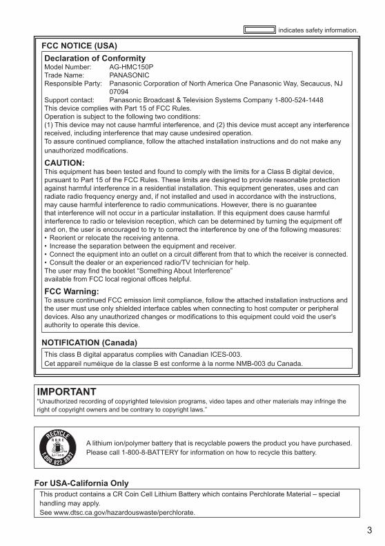
IMPORTANT“Unauthorized recording of copyrighted television programs, video tapes and other materials may infringe the right of copyright owners and be contrary to copyright laws.”
FCC NOTICE (USA)Declaration of ConformityModel Number: AG-HMC150PTrade Name: PANASONICResponsible Party: Panasonic Corporation of North America One Panasonic Way, Secaucus, NJ
07094Support contact: Panasonic Broadcast & Television Systems Company 1-800-524-1448This device complies with Part 15 of FCC Rules.Operation is subject to the following two conditions:(1) This device may not cause harmful interference, and (2) this device must accept any interference received, including interference that may cause undesired operation.To assure continued compliance, follow the attached installation instructions and do not make any unauthorized modifications.
CAUTION:This equipment has been tested and found to comply with the limits for a Class B digital device, pursuant to Part 15 of the FCC Rules. These limits are designed to provide reasonable protection against harmful interference in a residential installation. This equipment generates, uses and can radiate radio frequency energy and, if not installed and used in accordance with the instructions, may cause harmful interference to radio communications. However, there is no guarantee that interference will not occur in a particular installation. If this equipment does cause harmful interference to radio or television reception, which can be determined by turning the equipment off and on, the user is encouraged to try to correct the interference by one of the following measures:
Reorient or relocate the receiving antenna.Increase the separation between the equipment and receiver.Connect the equipment into an outlet on a circuit different from that to which the receiver is connected.Consult the dealer or an experienced radio/TV technician for help.
The user may find the booklet “Something About Interference”available from FCC local regional offices helpful.
FCC Warning:To assure continued FCC emission limit compliance, follow the attached installation instructions and the user must use only shielded interface cables when connecting to host computer or peripheral devices. Also any unauthorized changes or modifications to this equipment could void the user's authority to operate this device.
••••
NOTIFICATION (Canada)This class B digital apparatus complies with Canadian ICES-003.Cet appareil numéique de la classe B est conforme à la norme NMB-003 du Canada.
indicates safety information.
For USA-California Only This product contains a CR Coin Cell Lithium Battery which contains Perchlorate Material – special handling may apply.See www.dtsc.ca.gov/hazardouswaste/perchlorate.
A lithium ion/polymer battery that is recyclable powers the product you have purchased.Please call 1-800-8-BATTERY for information on how to recycle this battery.

4
IMPORTANT SAFETY INSTRUCTIONS1) Read these instructions.2) Keep these instructions.3) Heed all warnings.4) Follow all instructions.5) Do not use this apparatus near water.6) Clean only with dry cloth.7) Do not block any ventilation openings. Install in accordance with the manufacturer’s instructions.8) Do not install near any heat sources such as radiators, heat registers, stoves, or other apparatus
(including amplifiers) that produce heat.9) Do not defeat the safety purpose of the polarized or grounding-type plug. A polarized plug has two
blades with one wider than the other. A grounding-type plug has two blades and a third grounding prong. The wide blade or the third prong are provided for your safety. If the provided plug does not fit into your outlet, consult an electrician for replacement of the obsolete outlet.
10) Protect the power cord from being walked on or pinched particularly at plugs, convenience receptacles, and the point where they exit from the apparatus.
11) Only use attachments/accessories specified by the manufacturer.12) Use only with the cart, stand, tripod, bracket, or table specified by the manufacturer,
or sold with the apparatus. When a cart is used, use caution when moving the cart/ apparatus combination to avoid injury from tip-over.
13) Unplug this apparatus during lightning storms or when unused for long periods of time.14) Refer all servicing to qualified service personnel. Servicing is required when the
apparatus has been damaged in any way, such as power-supply cord or plug is damaged, liquid has been spilled or objects have fallen into the apparatus, the apparatus has been exposed to rain or moisture, does not operate normally, or has been dropped.
5
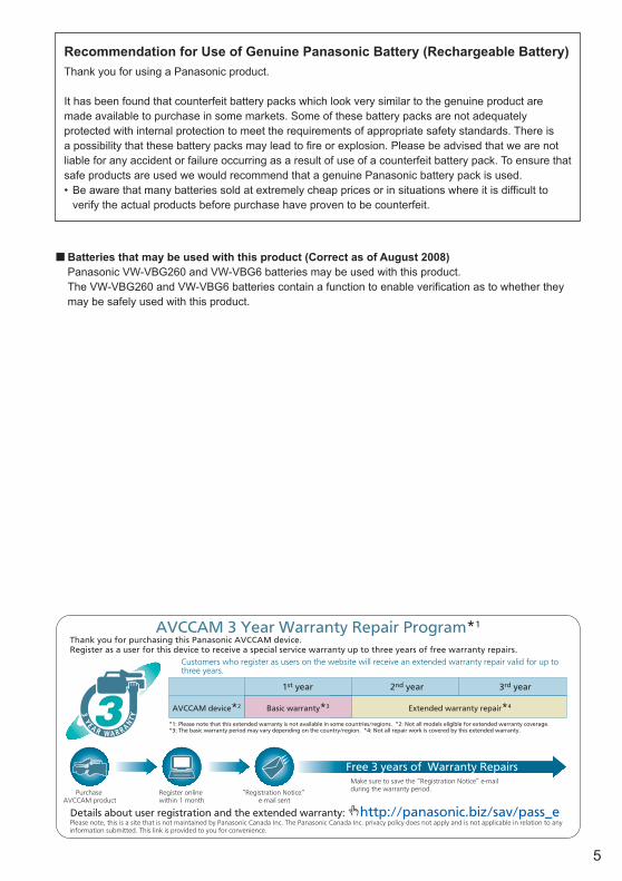
Recommendation for Use of Genuine Panasonic Battery (Rechargeable Battery)Thank you for using a Panasonic product.
It has been found that counterfeit battery packs which look very similar to the genuine product are made available to purchase in some markets. Some of these battery packs are not adequately protected with internal protection to meet the requirements of appropriate safety standards. There is a possibility that these battery packs may lead to fire or explosion. Please be advised that we are not liable for any accident or failure occurring as a result of use of a counterfeit battery pack. To ensure that safe products are used we would recommend that a genuine Panasonic battery pack is used.
Be aware that many batteries sold at extremely cheap prices or in situations where it is difficult to verify the actual products before purchase have proven to be counterfeit.
•
Batteries that may be used with this product (Correct as of August 2008) Panasonic VW-VBG260 and VW-VBG6 batteries may be used with this product. The VW-VBG260 and VW-VBG6 batteries contain a function to enable verification as to whether they
may be safely used with this product.
■
*1: Please note that this extended warranty is not available in some countries/regions. *2: Not all models eligible for extended warranty coverage.*3: The basic warranty period may vary depending on the country/region. *4: Not all repair work is covered by this extended warranty.
PurchaseAVCCAM product
Register online within 1 month
“Registration Notice” e-mail sent
Details about user registration and the extended warranty: http://panasonic.biz/sav/pass_e
Free 3 years of Warranty Repairs
Customers who register as users on the website will receive an extended warranty repair valid for up to three years.
AVCCAM 3 Year Warranty Repair Program*1
Thank you for purchasing this Panasonic AVCCAM device.Register as a user for this device to receive a special service warranty up to three years of free warranty repairs.
Make sure to save the “Registration Notice” e-mail during the warranty period.
Please note, this is a site that is not maintained by Panasonic Canada Inc. The Panasonic Canada Inc. privacy policy does not apply and is not applicable in relation to any information submitted. This link is provided to you for convenience.
1st year 2nd year 3rd year
AVCCAM device*2 Basic warranty*3 Extended warranty repair*4
6
ContentsRead this first! ................................................ 2IMPORTANT SAFETY INSTRUCTIONS ......... 4Recommendation for Use of Genuine
Panasonic Battery (Rechargeable Battery) .......................... 5
Outline of operations ..................................... 8Please read before use .................................. 9
SD Memory Cards compatible with this product ..... 9 (SD speed class 4) ........................ 10
Before usePrecaution for use ........................................ 11Accessories .................................................. 14Optional accessories ................................... 14
Description of partsDescription of parts ...................................... 15
Right side and rear side .................................. 15Left side ........................................................... 16Terminals and mounting parts ......................... 17Remote control ................................................ 18
PreparationRecharging the battery ................................ 18
Recharging ...................................................... 18Power sources .............................................. 20
Using the battery ............................................. 20Using the AC adapter ...................................... 20
Adjusting the hand strap ............................. 21Attaching the shoulder strap ....................... 21Detaching and attaching the lens hood ..... 21The remote control ....................................... 22
Insert the battery ............................................. 22Remote control usable range .......................... 22
Turn on/off the camera ................................. 22Standby mode ............................................... 23Tally lamp ...................................................... 23Viewfinder ..................................................... 24
Using the viewfinder ........................................ 24Using the LCD ................................................. 25Emphasizing outlines ...................................... 25Adjusting the screen display ............................ 26Changing backlight brightness ........................ 27Reversing image display ................................. 27
Setting the calendar ..................................... 28
ShootingBasic shooting operations .......................... 30
Preparing for recording .................................... 30Shooting in auto mode .................................... 30Checking photos taken (REC CHECK) ........... 31SD Memory Card access lamp ........................ 31Formatting SD Memory Cards ......................... 32SD Memory Card recording times ................... 32
Removing SD Memory Card ........................... 33Protecting SD Memory Cards .......................... 33Repairing SD Memory Cards .......................... 33
Using the zoom function .............................. 34Digital zoom function ....................................... 34
Shooting in progressive mode .................... 35Shooting in manual mode ............................ 36
Switching to manual mode ............................. 36Manual focusing ............................................. 36Using focus assist ........................................... 37Iris adjustments ............................................... 37Adjusting the gain ............................................ 38Light intensity adjustments .............................. 38Adjusting the white balance ............................. 38
Shooting techniques for different targets .. 41Low angle recording ........................................ 41Self-portrait shooting ...................................... 41Zebra pattern .................................................. 41Marker ............................................................. 42Checking and displaying shooting status ........ 42PRE REC ........................................................ 42Optical Image Stabilizer .................................. 43Adding effects to images ................................. 43Using the USER buttons ................................ 43Backlight compensation .................................. 43Color bars ........................................................ 43Wave form monitor function ............................. 44Adjusting the volume while shooting ............... 44Shot mark function .......................................... 45Index recording ................................................ 45Time stamp function ........................................ 45LAST CLIP function ......................................... 45
Adjusting the shutter speed ........................ 46Synchro scan ................................................... 47
Switching Audio Input .................................. 48Using the built-in microphone .......................... 48Using an external microphone and audio
equipment .................................................... 48Adjusting the recording level ........................... 49
Using scene files .......................................... 50Changing scene file settings ........................... 50
Saving scene files and other settings on SD Memory Cards ........................................ 52
Clip metadata ................................................ 53Uploading the metadata (META DATA) ........... 54Selecting the USER CLIP NAME
recording method ........................................ 54Using the Counter ........................................ 55
Counter display ............................................... 55TC preset mode ............................................... 55
Charging the built-in battery/Setting the time code ........................... 56
Recharging the built-in battery ........................ 56Setting the time code ....................................... 56Specifying the time code (TC PRESET) .......... 56Setting user information .................................. 58
7
PlaybackBasic playback operations .......................... 59Thumbnail screen ......................................... 60
Basic thumbnail screen operations ................. 60Adding shot marks to clips .............................. 62Direct shooting functions ................................. 62
Playback settings (PLAY SETUP)................ 63Set playback format (PB FORMAT)................. 63Repeat playback (REPEAT PLAY) .................. 63Resume playback (RESUME PLAY) ............... 64Set skip method (SKIP MODE) ....................... 64
Thumbnail operations .................................. 65Selecting the thumbnail display method
(THUMBNAIL SETUP) ................................ 65Deleting and protecting clips (OPERATION) ... 66Format card and check clip and
card information (CARD FUNCTIONS) ....... 67Useful playback functions ........................... 69
Fast forward/rewind ......................................... 69Next/previous clip ............................................ 69Frame-by-frame playback ............................... 70Adjust volume .................................................. 70Viewing images on a television ....................... 70Checking the date and time ............................. 70
EditingConnecting external units ........................... 71
Headphones .................................................... 71External microphone ....................................... 71Computer (non-linear editing/file transfer) ....... 72Video deck (Dubbing) ...................................... 72TV/Monitor ....................................................... 73
Nonlinear editing (PC mode) ....................... 75
DisplaysScreen displays ............................................ 76
Regular displays .............................................. 76Main warning displays ..................................... 79Setting the DISPLAY items .............................. 81
MenuUsing the setup menus ................................ 82
Using the menus ............................................. 82Initializing the menu settings ........................... 83
Setup menu structure .................................. 84Camera mode menu ........................................ 84Playback mode menu ...................................... 85
Setup menu list ............................................. 86SCENE FILE screen ........................................ 86SW MODE screen ........................................... 88AUTO SW screen ............................................ 90RECORDING SETUP screen .......................... 91TC/UB SETUP screen ..................................... 92AV OUT SETUP screen ................................... 93DISPLAY SETUP screen ................................. 94CARD FUNCTIONS screen ............................ 96USER FILE screen .......................................... 96META DATA screen ......................................... 96PLAY SETUP screen ....................................... 97THUMBNAIL SETUP screen ........................... 97OPERATION screen ........................................ 98OTHER FUNCTIONS screen .......................... 98
ReferenceBefore calling for service........................... 100Operating precautions ............................... 104Updating the driver in the camera ............ 106Cleaning ...................................................... 106Storage Precautions................................... 107Recording format ........................................ 108How to handle data recorded on
SD Memory Card ................................. 109Specifications ............................................. 110
8
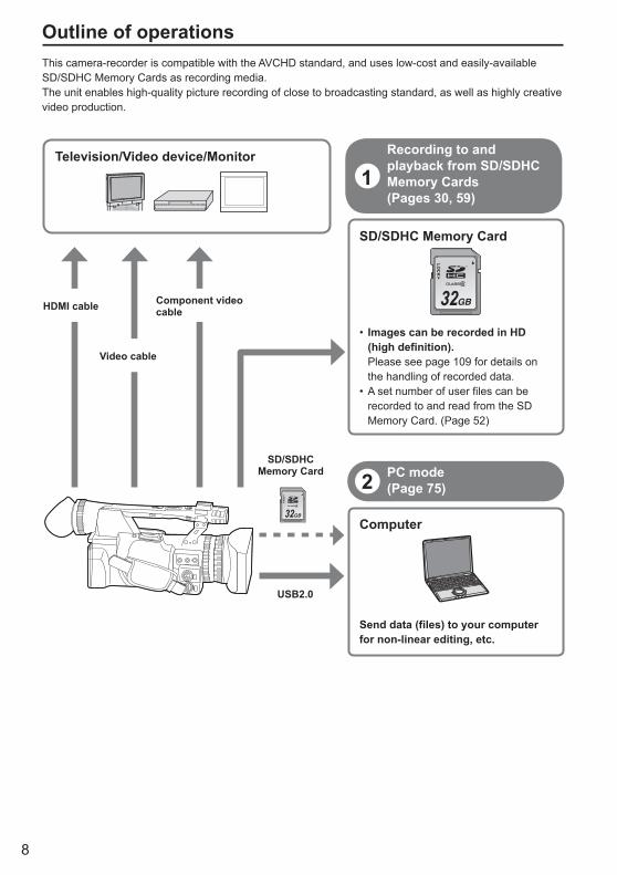
Outline of operationsThis camera-recorder is compatible with the AVCHD standard, and uses low-cost and easily-available SD/SDHC Memory Cards as recording media.The unit enables high-quality picture recording of close to broadcasting standard, as well as highly creative video production.
SD/SDHC Memory Card
32
LOC
K
Images can be recorded in HD (high definition).Please see page 109 for details on the handling of recorded data.A set number of user files can be recorded to and read from the SD Memory Card. (Page 52)
•
•
Computer
Send data (files) to your computer for non-linear editing, etc.
2 PC mode(Page 75)
USB2.0
Recording to and playback from SD/SDHC Memory Cards(Pages 30, 59)
1
32
LOC
K
SD/SDHC Memory Card
Television/Video device/Monitor
HDMI cable
Video cable
Component video cable

9
Please read before useSD Memory Cards compatible with this product
It is recommended that you use SD Memory Cards or SDHC Memory Cards∗ of SD speed class 2 or above, or the following Panasonic SD Memory Cards (correct as of August 2008).∗ Speed class 4 or above is required for recording in PH mode or HA mode.
Card type Recording capacity Recording/playback Saving/reading of scene files and user files, reading of metadata
SD Memory Card
8 MB16 MB Cannot be used.
Can be used.
32 MB64 MB
128 MB256 MB
Successful operation cannot be guaranteed. Recording may be suddenly terminated with certain SD Memory Cards.
512 MB RP-SDV512
1 GB RP-SDV01GRP-SDM01G
2 GB RP-SDV02GRP-SDM02G
SDHC Memory Card
4 GB RP-SDV04GRP-SDM04G
6 GB RP-SDM06G
8 GB RP-SDV08GRP-SDM08G
12 GB RP-SDM12G
16 GBRP-SDV16GRP-SDM16GAG-SDV016G
32 GB RP-SDV32GAG-SDV032G
Please see our support page at the following website for the latest information not included in these operating instructions.https://eww.pavc.panasonic.co.jp/pro-av/ This product is compatible with SD Memory Cards formatted under the SD-standard FAT12 and FAT16 formats, and with SDHC Memory Cards formatted under the FAT32 format.Only SDHC Memory Cards may be used for capacities of 4 GB or greater.4 GB (or greater) memory cards without the SDHC logo are not based on the SD standard.Use this product to format the SD Memory Cards to be used. Formatting memory cards on computers or other devices may cause recording to take longer than normal, or may cause cards to become incompatible with this product. (Page 32) (Use this product to reformat any cards that have already been formatted on computers, etc.)Always install the relevant special adapter when using miniSD/miniSDHC cards with this product. (The product will not operate correctly if only the adapter is inserted – always insert a memory card into the adapter first.)MultiMediaCards cannot be used with this product.
•
•
•••
•
•
(Continued on the next page)

10
This product (SDHC-compatible device) is compatible both with SD Memory Cards and with SDHC Memory Cards. SDHC Memory Cards may be used with SDHC Memory Card-compatible devices, but cannot be used with devices that are only compatible with SD Memory Cards. (Always check the relevant product’s operating instructions when using SDHC Memory Cards with other devices.)
SDHC-compatible device
SDHC Memory Card SD Memory Card SDHC Memory Card SD Memory Card
Can be used Can be used Cannot be used Can be used
SD-compatible device
(SD speed class 4)
This refers to a class 4 speed standard (SD speed class) for the continuous writing of data between SD-compatible devices and SD Memory Cards, as designated by the SD standards.When the use of an SD speed class 4 card is recommended for SD-compatible products, this indicates that stable recording operation can be achieved when using SD Memory Cards of class 4 and above.
Cautions for usageDo not allow dirt, water, or other substances to come into contact with the connector part on the reverse of the card.Do not leave the card in the following places:
– In direct sunlight or in places of high humidity, e.g. close to heating equipment – In highly humid or dusty locations – In locations with high variations in temperature (condensation may appear on card) – In places subject to static electricity or electromagnetic waves
Store cards in bags or cases after use.
•
•
•
Please read before use (continued)
11
Bef
ore
use
Precaution for useAlways take some trial shots before actual shooting.
When shooting important events (such as weddings), always take some trial shots and check that the sound and images have been recorded properly before actual shooting.
Be sure to check and set the calendar and time zone.These settings affect the control and playback sequence of the recorded contents. Before making a recording, set and check the calendar and time zone. (Page 28)
Panasonic makes no guarantees for your recordings.Please understand that Panasonic makes no guarantees for your recordings in cases where images and/ or sound were not recorded as you intended due to problems with the camera-recorder or SD/SDHC Memory Cards.
Respect copyrightsCopyright laws forbid the use of video and audio material you have recorded for any purpose other than your own personal enjoyment. Remember that restrictions apply to the shooting of certain material even if it is intended for private use.
Caution regarding laser beamsThe CCD may be damaged if it is subjected to light from a laser beam.When using the camera-recorder in locations where laser irradiation equipment is used, be careful not to allow the laser beam to shine directly on the lens.
Media that can be used in this unitSD/SDHC Memory Cards can be used in this unit. For details, refer to page 9.
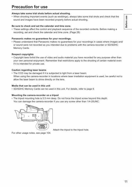
Mounting the camera-recorder on a tripodThe tripod mounting hole is 5.5 mm deep. Do not force the tripod screw beyond this depth.You can damage the camera-recorder if you use any screw other than 1/4-20UNC.
Attach the tripod to the tripod hole.For other usage notes, see page 104.
•
•
•
•
•
•
•
12
The SDHC logo is a trademark.The miniSD logo is a trademark.“AVCHD” and the “AVCHD” logo are trademarks of Matsushita Electric Industrial Co., Ltd. and Sony Corporation.This product has been manufactured under license from Dolby Laboratories. Dolby and the double-D symbol are trademarks of Dolby Laboratories.HDMI, the HDMI logo, and High-Definition Multimedia Interface are trademarks or registered trademarks of HDMI Licensing LLC.LEICA is a registered trademark of Leica Microsystems IR GmbH.DICOMAR is a registered trademark of Leica Camera AG.Microsoft®, Windows®, and Windows Vista® are either registered trademarks or trademarks of Microsoft Corporation in the United States and/or other countries.Screenshots are used in accordance with Microsoft Corporation guidelines.IBM and PC/AT are registered trademarks of International Business Machines Corporation.Intel® is a registered trademark or a trademark of Intel Corporation in the United States and/or other countries.Macintosh® is a trademark of Apple Inc., registered in the United States and other countries.Other model names, company names, and product names listed in these operating instructions are trademarks or registered trademarks of their respective companies.
●●●
●
●
●
●
●
●
●
●
●
●
This product is licensed under the AVC Patent Portfolio License for the personal and non-commercial use of a consumer, and no license is granted or shall be implied for any use other than the personal uses detailed below.
– To encode video in compliance with the AVC standard (“AVC Video”)
– To decode AVC Video that was encoded by a consumer engaged in a personal and non-commercial activity
– To decode AVC Video that was obtained from a video provider licensed to provide AVC Video• Additional information may be obtained from
MPEG LA, LLC (http://www.mpegla.com). – Separate license contracts must be obtained from
MPEG LA where SD Memory Cards containing information recorded with this product are to be distributed to end users for commercial purposes. “End user” refers to persons or organizations handling such contents for personal use.
●
About this manualNote concerning illustrations in these instructions
Illustrations (camera-recorder, menu screens, etc.) in these operating instructions differ slightly from the actual camera-recorder.
ReferencesReferences are shown as (Page 00).
SD/SDHC Memory CardsBoth SD Memory Cards and SDHC Memory Cards as referred to as “SD Memory Cards” in these operating instructions.
•
•
•
Precaution for use (continued)

13
Bef
ore
use
What is AVCHD? AVCHD is a standard for the recording and playback of highly detailed, high-definition video. Video is compressed in the MPEG-4 AVC/H.264 formats, and audio is recorded in Dolby Digital.
Information regarding compatibility of SDHC Memory Cards and recorded video
SDHC Memory CardsSDHC Memory Cards cannot be used with non-SDHC-compatible equipment.Ensure that all equipment is SDHC-compatible when using card with other devices.(Page 10)
●●
Compatibility of recorded videoRecorded video cannot be used with non-AVCHD-compatible equipment. For details, please see your product’s operating instructions.Recorded video cannot be played back on non-compatible (non-AVCHD-compatible) equipment.Playback may not always be possible on all AVCHD-compatible equipment. Please use this product for playback in such instances.
●
●
●Older, non-AVCHD-compatible DVD recorder or DVD player, etc.
14
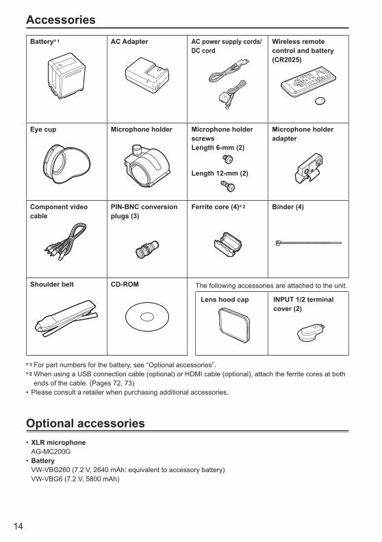
AccessoriesBattery∗1 AC Adapter AC power supply cords/
DC cordWireless remote control and battery (CR2025)
Eye cup Microphone holder Microphone holder screwsLength 6-mm (2)
Length 12-mm (2)
Microphone holder adapter
Component video cable
PIN-BNC conversion plugs (3)
Ferrite core (4)∗2 Binder (4)
Shoulder belt CD-ROM The following accessories are attached to the unit.
Lens hood cap INPUT 1/2 terminal cover (2)
∗1 For part numbers for the battery, see “Optional accessories”.∗2 When using a USB connection cable (optional) or HDMI cable (optional), attach the ferrite cores at both
ends of the cable. (Pages 72, 73)Please consult a retailer when purchasing additional accessories.
Optional accessoriesXLR microphone
AG-MC200GBattery
VW-VBG260 (7.2 V, 2640 mAh: equivalent to accessory battery) VW-VBG6 (7.2 V, 5800 mAh)
•
•
•
15
Des
crip
tion
of p
arts
Bef
ore
use
Description of partsRight side and rear side
PB
3 58
1110 12
1 2
47 9 14
15
1617
1819
20 2221
1323
6
1
2
POWERON
OFF
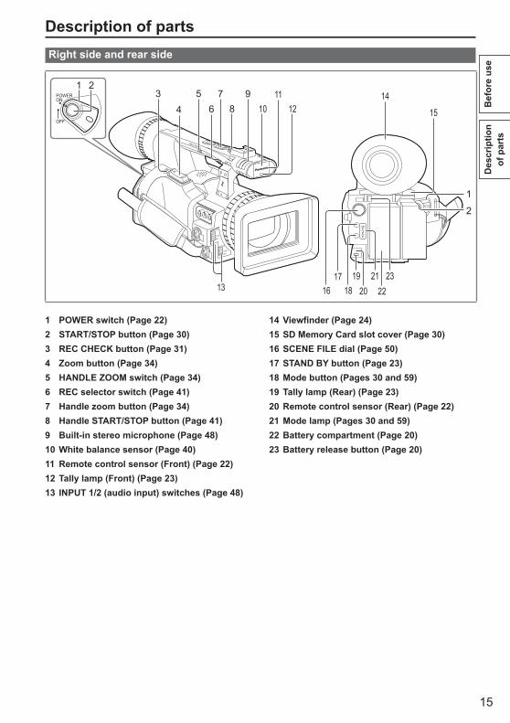
1 POWER switch (Page 22)2 START/STOP button (Page 30)3 REC CHECK button (Page 31)4 Zoom button (Page 34)5 HANDLE ZOOM switch (Page 34)6 REC selector switch (Page 41)7 Handle zoom button (Page 34)8 Handle START/STOP button (Page 41)9 Built-in stereo microphone (Page 48)10 White balance sensor (Page 40)11 Remote control sensor (Front) (Page 22)12 Tally lamp (Front) (Page 23)13 INPUT 1/2 (audio input) switches (Page 48)
14 Viewfinder (Page 24)15 SD Memory Card slot cover (Page 30)16 SCENE FILE dial (Page 50)17 STAND BY button (Page 23)18 Mode button (Pages 30 and 59)19 Tally lamp (Rear) (Page 23)20 Remote control sensor (Rear) (Page 22)21 Mode lamp (Pages 30 and 59)22 Battery compartment (Page 20)23 Battery release button (Page 20)

16
Description of parts (continued)
Left side
21
AWB
BARS
LCD
ZEBRA OIS
EVF DTL WFM
CH1 SELECT CH2 SELECT INPUT 1 INPUT 2
SHUTTER
COUNTER RESET/TC SETAUDIO
SPEED SELECT
INT(L)INPUT1INPUT2
INT(R)INPUT2
ON
MIC POWER +48V
OFFON
OFF
MENU
PUSH-ENTER
AUDIO MON/ADV
EXEC
2726 28 29
31 33 34 35
22 23
2425
1 62 7
2011 12 1413 15 16 1817 19
3 54
30 3210
8
9
1 Focus ring (Page 36)2 Zoom ring (Page 34)
If you don’t need the zoom ring pin, fit it into the provided pin holder (next page 4) so that you don’t lose it.
3 FOCUS ASSIST button (Page 37)4 USER buttons (Pages 43 and 88)5 ZOOM switch (Page 34)6 Built-in speaker (Page 70)7 Diopter adjustment dial (Page 24)8 FOCUS switch (Page 36)9 PUSH AUTO button (Page 36)10 AWB button (Page 38)11 IRIS dial (Page 37)12 ND FILTER switch (Page 38)13 IRIS button (Page 37)14 GAIN switch (Page 38)15 WHITE BAL switch (Page 38)16 RING (FOCUS/IRIS) selector switch
(Page 36)17 DISP/MODE CHK button (Page 42)18 AUTO/MANUAL switch (Pages 30 and 36)
19 AUDIO control knobs (CH1, CH2) (Page 49)20 LCD monitor (Page 25)21 OPEN button (Page 25)22 MENU button (Page 82)23 EXEC button (Page 66)24 Operation lever (Page 82)25 AUDIO MON/ADV buttons (Pages 44, 70)26 CH1, CH2 SELECT switches (Page 48)27 BARS button (Page 43)28 SHUTTER, SPEED SELECT+/- buttons
(Page 46)29 INPUT 1/2 switches (MIC POWER +48 V)
(Page 48)30 COUNTER - RESET/TC SET buttons
(Page 55)31 LCD button (Page 27)32 ZEBRA button (Page 41)33 EVF DTL button (Page 25)34 WFM button (Page 44)35 OIS button (Page 43)

17
Des
crip
tion
of p
arts
Terminals and mounting parts
2 9 103
5 7 86
41
COMPONENTOUT
CAM REMOTE
FOCUS IRISZOOM S/S
USB 2.0
VIDEO OUT
TCPRESET
IN/OUT
AUDIO OUTCH1 CH2
151411 1213COMPONENT
OUT
CAM REMOTE
ZOOM S/SFOCUS IRIS
USB 2.0
1 Security lock holeThe security cable can be attached here.For details on the connection, refer to the instructions supplied to the cable.The security lock and security cable are provided as anti-theft devices. Nevertheless, the manufacturer will assume no liability for any damage which may be sustained in the event of theft.
2 Light shoe3 Microphone shoe (Page 71)4 Pin holder (for zoom ring pin)
(previous page 2)5 Tripod hole (Page 11)6 AUDIO OUT CH1/CH2 terminals
(Pages 72 and 73)7 VIDEO OUT terminal (Pages 72 and 73)8 INPUT 1/2 terminals (XLR 3 pin) (Page 71)9 SD Memory Card slot (Page 30)10 SD Memory Card access lamp (Page 31)11 USB terminal (Mini-B) (Pages 72 and 75)12 HDMI OUT terminal (Page 73)13 COMPONENT OUT terminal (Page 73)
14 CAM REMOTE jack∗
FOCUS/IRIS (3.5 mm mini jack) You can connect a remote control unit (optional)
to control the FOCUS and IRIS (aperture). ZOOM S/S (2.5 mm super mini jack) You can connect a remote control unit to control
zoom and start/stop of recording.15 Headphone jack (3.5 mm stereo mini jack)
(Page 71)
∗ Do not connect any equipment except the remote controller to the remote control jack. Connecting any equipment other than the remote control may cause the image brightness to change and/or the images to appear out of focus.
18
Description of parts (continued)
Remote control
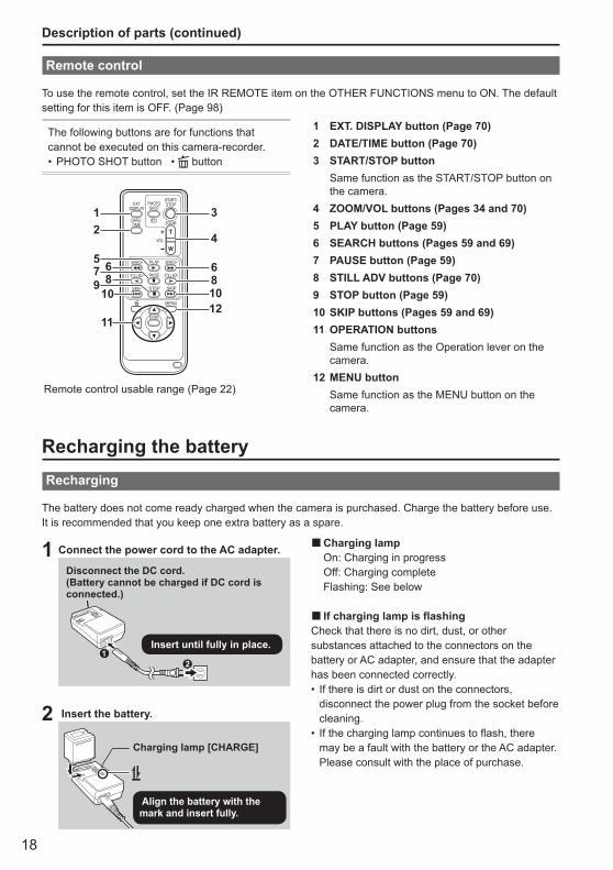
To use the remote control, set the IR REMOTE item on the OTHER FUNCTIONS menu to ON. The default setting for this item is OFF. (Page 98)
The following buttons are for functions that cannot be executed on this camera-recorder.
PHOTO SHOT button • button•
1 EXT. DISPLAY button (Page 70)2 DATE/TIME button (Page 70)3 START/STOP button Same function as the START/STOP button on
the camera.4 ZOOM/VOL buttons (Pages 34 and 70)5 PLAY button (Page 59)6 SEARCH buttons (Pages 59 and 69)7 PAUSE button (Page 59)8 STILL ADV buttons (Page 70)9 STOP button (Page 59)10 SKIP buttons (Pages 59 and 69)11 OPERATION buttons Same function as the Operation lever on the
camera.12 MENU button Same function as the MENU button on the
camera.
ZOOM
START/STOPPHOTO
SHOTEXT
DISPLAY
DATE/TIME
VOL
PLAY
STOPSKIP SKIP
MENU
ENTER
PAUSE
SEARCH
STILL ADV STILL ADV
SEARCH
3
4
68
12
57 89
10
11
6
1012
Remote control usable range (Page 22)
Recharging the batteryRecharging
The battery does not come ready charged when the camera is purchased. Charge the battery before use.It is recommended that you keep one extra battery as a spare.
1 Connect the power cord to the AC adapter.
Disconnect the DC cord. (Battery cannot be charged if DC cord is connected.)
Insert until fully in place.
2 Insert the battery.
Charging lamp [CHARGE]
Align the battery with the mark and insert fully.
Charging lamp On: Charging in progress Off: Charging complete Flashing: See below
If charging lamp is flashingCheck that there is no dirt, dust, or other substances attached to the connectors on the battery or AC adapter, and ensure that the adapter has been connected correctly.
If there is dirt or dust on the connectors, disconnect the power plug from the socket before cleaning.If the charging lamp continues to flash, there may be a fault with the battery or the AC adapter. Please consult with the place of purchase.
■
■
•
•
19
Prep
arat
ion
Des
crip
tion
of p
arts
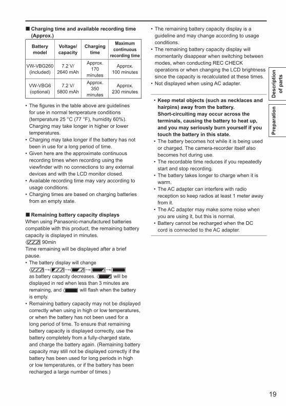
Charging time and available recording time (Approx.)
Battery model
Voltage/capacity
Charging time
Maximum continuous
recording time
VW-VBG260 (included)
7.2 V/2640 mAh
Approx. 170
minutes
Approx. 100 minutes
VW-VBG6 (optional)
7.2 V/5800 mAh
Approx. 350
minutes
Approx. 230 minutes
The figures in the table above are guidelines for use in normal temperature conditions (temperature 25 °C (77 °F), humidity 60%). Charging may take longer in higher or lower temperatures.Charging may take longer if the battery has not been in use for a long period of time.Given here are the approximate continuous recording times when recording using the viewfinder with no connections to any external devices and with the LCD monitor closed.Available recording time may vary according to usage conditions.Charging times are based on charging batteries from an empty state.
Remaining battery capacity displaysWhen using Panasonic-manufactured batteries compatible with this product, the remaining battery capacity is displayed in minutes.
90minTime remaining will be displayed after a brief pause.
The battery display will change→ → → →
as battery capacity decreases. will be displayed in red when less than 3 minutes are remaining, and will flash when the battery is empty.Remaining battery capacity may not be displayed correctly when using in high or low temperatures, or when the battery has not been used for a long period of time. To ensure that remaining battery capacity is displayed correctly, use the battery completely from a fully-charged state, and charge the battery again. (Remaining battery capacity may still not be displayed correctly if the battery has been used for long periods in high or low temperatures, or if the battery has been recharged a large number of times.)
■
•
•
•
•
•
■
•
•
The remaining battery capacity display is a guideline and may change according to usage conditions.The remaining battery capacity display will momentarily disappear when switching between modes, when conducting REC CHECK operations or when changing the LCD brightness since the capacity is recalculated at these times.Not displayed when using AC adapter.
Keep metal objects (such as necklaces and hairpins) away from the battery. Short-circuiting may occur across the terminals, causing the battery to heat up, and you may seriously burn yourself if you touch the battery in this state.The battery becomes hot while it is being used or charged. The camera-recorder itself also becomes hot during use.The recordable time reduces if you repeatedly start and stop recording.The battery takes longer to charge when it is warm.The AC adapter can interfere with radio reception so keep radios at least 1 meter away from it.The AC adapter may make some noise when you are using it, but this is normal.Battery cannot be recharged when the DC cord is connected to the AC adapter.
•
•
•
•
•
•
•
•
•
•
20
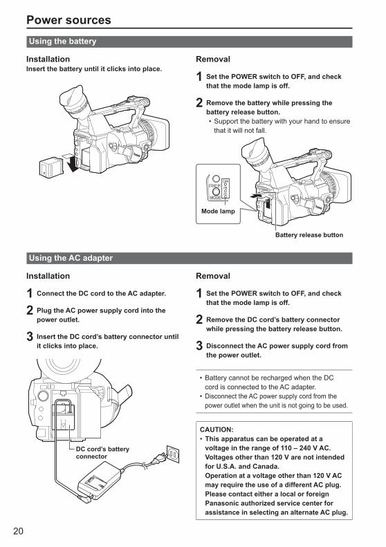
Power sourcesUsing the battery
InstallationInsert the battery until it clicks into place.
Removal
1 Set the POWER switch to OFF, and check that the mode lamp is off.
2 Remove the battery while pressing the battery release button.
Support the battery with your hand to ensure that it will not fall.
Mode lamp
Battery release button
PB
•
Using the AC adapter
Installation
1 Connect the DC cord to the AC adapter.
2 Plug the AC power supply cord into the power outlet.
3 Insert the DC cord’s battery connector until it clicks into place.
DC cord’s battery connector
Removal
1 Set the POWER switch to OFF, and check that the mode lamp is off.
2 Remove the DC cord’s battery connector while pressing the battery release button.
3 Disconnect the AC power supply cord from the power outlet.
Battery cannot be recharged when the DC cord is connected to the AC adapter.Disconnect the AC power supply cord from the power outlet when the unit is not going to be used.
•
•
CAUTION:This apparatus can be operated at a voltage in the range of 110 – 240 V AC. Voltages other than 120 V are not intended for U.S.A. and Canada. Operation at a voltage other than 120 V AC may require the use of a different AC plug. Please contact either a local or foreign Panasonic authorized service center for assistance in selecting an alternate AC plug.
•
21
Prep
arat
ion
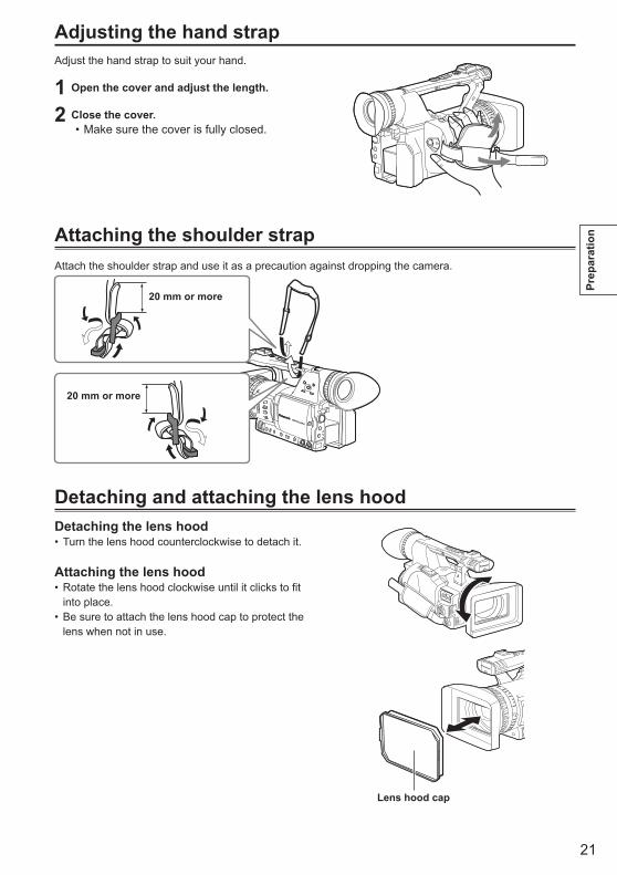
Adjusting the hand strapAdjust the hand strap to suit your hand.
1 Open the cover and adjust the length.
2 Close the cover.Make sure the cover is fully closed.•
Attaching the shoulder strapAttach the shoulder strap and use it as a precaution against dropping the camera.
20 mm or more
20 mm or more
Detaching and attaching the lens hoodDetaching the lens hood
Turn the lens hood counterclockwise to detach it.
Attaching the lens hoodRotate the lens hood clockwise until it clicks to fit into place.Be sure to attach the lens hood cap to protect the lens when not in use.
•
•
•
Lens hood cap
22
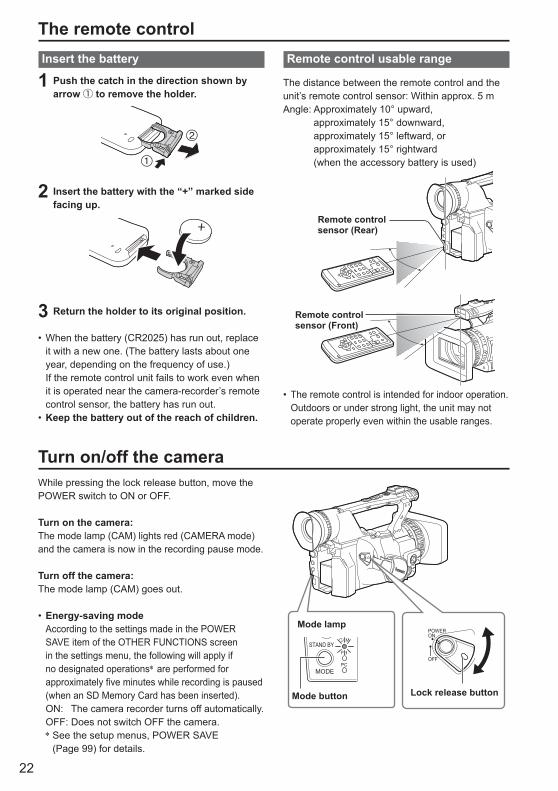
The remote controlInsert the battery
1 Push the catch in the direction shown by arrow ① to remove the holder.
2 Insert the battery with the “+” marked side facing up.
3 Return the holder to its original position.
When the battery (CR2025) has run out, replace it with a new one. (The battery lasts about one year, depending on the frequency of use.)
If the remote control unit fails to work even when it is operated near the camera-recorder’s remote control sensor, the battery has run out.Keep the battery out of the reach of children.
•
•
Remote control usable range
The distance between the remote control and theunit’s remote control sensor: Within approx. 5 mAngle: Approximately 10° upward,
approximately 15° downward, approximately 15° leftward, or approximately 15° rightward(when the accessory battery is used)
Remote control sensor (Rear)
Remote control sensor (Front)
The remote control is intended for indoor operation. Outdoors or under strong light, the unit may not operate properly even within the usable ranges.
•
Turn on/off the cameraWhile pressing the lock release button, move the POWER switch to ON or OFF.
Turn on the camera:The mode lamp (CAM) lights red (CAMERA mode) and the camera is now in the recording pause mode.
Turn off the camera:The mode lamp (CAM) goes out.
Energy-saving mode According to the settings made in the POWER
SAVE item of the OTHER FUNCTIONS screen in the settings menu, the following will apply if no designated operations∗ are performed for approximately five minutes while recording is paused (when an SD Memory Card has been inserted).
ON: The camera recorder turns off automatically. OFF: Does not switch OFF the camera. ∗ See the setup menus, POWER SAVE
(Page 99) for details.
•Mode lamp
STAND BY
MODE
CAM
PB
PC
Mode button Lock release button
POWERON
OFF
23
Prep
arat
ion
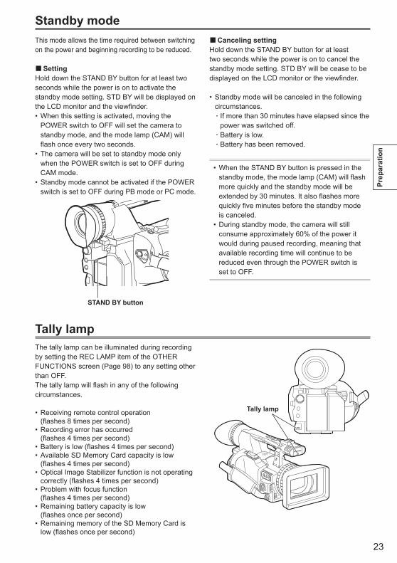
Standby modeThis mode allows the time required between switching on the power and beginning recording to be reduced.
SettingHold down the STAND BY button for at least two seconds while the power is on to activate the standby mode setting. STD BY will be displayed on the LCD monitor and the viewfinder.
When this setting is activated, moving the POWER switch to OFF will set the camera to standby mode, and the mode lamp (CAM) will flash once every two seconds.The camera will be set to standby mode only when the POWER switch is set to OFF during CAM mode.Standby mode cannot be activated if the POWER switch is set to OFF during PB mode or PC mode.
STAND BY button
■
•
•
•
Canceling settingHold down the STAND BY button for at least two seconds while the power is on to cancel the standby mode setting. STD BY will be cease to be displayed on the LCD monitor or the viewfinder.
Standby mode will be canceled in the following circumstances.
If more than 30 minutes have elapsed since the power was switched off. Battery is low.Battery has been removed.
When the STAND BY button is pressed in the standby mode, the mode lamp (CAM) will flash more quickly and the standby mode will be extended by 30 minutes. It also flashes more quickly five minutes before the standby mode is canceled.During standby mode, the camera will still consume approximately 60% of the power it would during paused recording, meaning that available recording time will continue to be reduced even through the POWER switch is set to OFF.
•
•
■
•
·
··
Tally lampThe tally lamp can be illuminated during recording by setting the REC LAMP item of the OTHER FUNCTIONS screen (Page 98) to any setting other than OFF.The tally lamp will flash in any of the following circumstances.
Receiving remote control operation (flashes 8 times per second)Recording error has occurred (flashes 4 times per second)Battery is low (flashes 4 times per second)Available SD Memory Card capacity is low (flashes 4 times per second)Optical Image Stabilizer function is not operating correctly (flashes 4 times per second)Problem with focus function (flashes 4 times per second)Remaining battery capacity is low (flashes once per second)Remaining memory of the SD Memory Card is low (flashes once per second)
•
•
••
•
•
•
•
Tally lamp
24
This camera has two viewfinders; one is a miniature LCD in the viewfinder and the other is a retractable 3.5-inch LCD.Use the viewfinder that best suits the application and shooting conditions.
The brightness and hue may differ between the images appearing on the viewfinder and LCD monitor and those displayed on a TV monitor. To see how the final images will appear, check them on a TV monitor.
Using the viewfinder
1 Set the POWER switch to ON and check that images appear in the viewfinder.
POWERON
OFF
2 Adjust the viewfinder’s angle so that the screen is positioned where it is easiest to see.
You can move the viewfinder out to about 90° perpendicular to the camera.
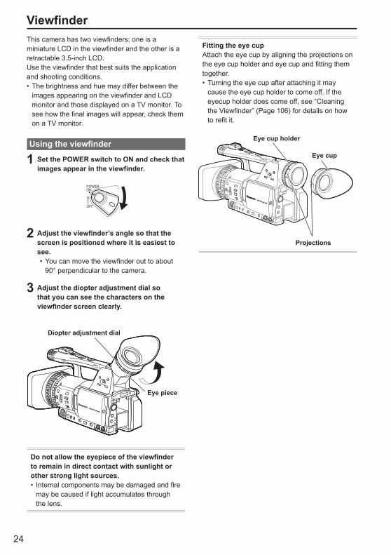
3 Adjust the diopter adjustment dial so that you can see the characters on the viewfinder screen clearly.
Diopter adjustment dial
Eye piece
Do not allow the eyepiece of the viewfinder to remain in direct contact with sunlight or other strong light sources.
Internal components may be damaged and fire may be caused if light accumulates through the lens.
•
•
•
Viewfinder
Fitting the eye cupAttach the eye cup by aligning the projections on the eye cup holder and eye cup and fitting them together.
Turning the eye cup after attaching it may cause the eye cup holder to come off. If the eyecup holder does come off, see “Cleaning the Viewfinder” (Page 106) for details on how to refit it.
Eye cup holder
Eye cup
Projections
•
25
Prep
arat
ion
Using the LCD
1 Set the POWER switch to ON.(Page 22)
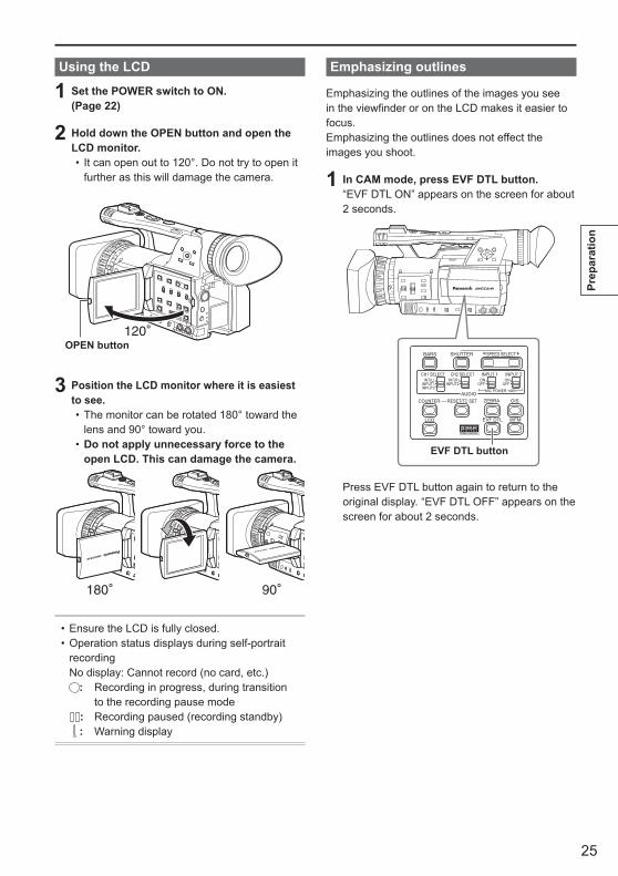
2 Hold down the OPEN button and open the LCD monitor.
It can open out to 120°. Do not try to open it further as this will damage the camera.
OPEN button
3 Position the LCD monitor where it is easiest to see.
The monitor can be rotated 180° toward the lens and 90° toward you.Do not apply unnecessary force to the open LCD. This can damage the camera.
Ensure the LCD is fully closed.Operation status displays during self-portrait recordingNo display: Cannot record (no card, etc.)
: Recording in progress, during transition to the recording pause mode
: Recording paused (recording standby) : Warning display
••
•
•
•
Emphasizing outlines
Emphasizing the outlines of the images you see in the viewfinder or on the LCD makes it easier to focus.Emphasizing the outlines does not effect the images you shoot.
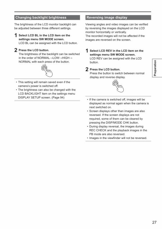
1 In CAM mode, press EVF DTL button.“EVF DTL ON” appears on the screen for about 2 seconds.
BARS
LCD
ZEBRA OIS
EVF DTL WFM
CH1 SELECT CH2 SELECT INPUT 1 INPUT 2
SHUTTER
COUNTER RESET/TC SETAUDIO
SPEED SELECT
INT(L)INPUT1INPUT2
INT(R)INPUT2
ON
MIC POWER +48V
OFFON
OFF
EVF DTL button
Press EVF DTL button again to return to the original display. “EVF DTL OFF” appears on the screen for about 2 seconds.

26
1 Set the POWER switch to ON. (Page 22)
2 Press the MENU button.For menu operation (Page 82)Operations may also be performed using buttons on the remote control that correspond to those on the camera. For details, see “Description of parts (Remote control)”. (Page 18)
3 Viewfinder adjustmentsSet YES under EVF SET on the setting menu DISPLAY SETUP screen.
LCD monitor adjustmentsSet YES under LCD SET on the setting menu DISPLAY SETUP screen.
4 Select the desired item by tilting the Operation lever in the directions, and push the Operation lever.
••
5 Adjust the selected item by tilting the Operation lever in the directions.
6 Press MENU button to exit the menus.
The viewfinder display can be in color or black and white. (See the setup menus, DISPLAY SETUP screen, EVF COLOR.) The resolution is the same for both of them.
•
Adjusting the screen display
Viewfinder (continued)
27
Prep
arat
ion
Changing backlight brightness
The brightness of the LCD monitor backlight can be adjusted between three different settings.
1 Select LCD BL in the LCD item on the settings menu SW MODE screen.LCD BL can be assigned with the LCD button.
2 Press the LCD button.The brightness of the backlight can be switched in the order of NORMAL→LOW→HIGH→NORMAL with each press of the button.
LCD
This setting will remain saved even if the camera’s power is switched off.The brightness can also be changed with the LCD BACKLIGHT item on the settings menu DISPLAY SETUP screen. (Page 94)
•
•
Reversing image display
Viewing angles and video images can be verified by reversing the images displayed on the LCD monitor horizontally or vertically.The recorded images will not be affected if the images are reversed on the screen.
1 Select LCD REV in the LCD item on the settings menu SW MODE screen.LCD REV can be assigned with the LCD button.
2 Press the LCD button.Press the button to switch between normal display and reverse display.
LCD
If the camera is switched off, images will be displayed as normal again when the camera is next switched on.Screen displays other than images are also reversed. If the screen displays are not required, some of them can be cleared by pressing the DISP/MODE CHK button.During display reversal, the images during REC CHECK and the playback images in the PB mode are also reversed.Images in the viewfinder will not be reversed.
•
•
•
•

28
The CLOCK SET value is recorded in the contents (clip), and affects the sequence of playback of the thumbnails. Before carrying out recording, be sure to check and set CLOCK SET and TIME ZONE.This shows you how to adjust the calendar to 17:20 on December 25, 2008.
1 Set the camera’s power switch to ON. (Page 22)
2 Press the MENU button.Menu operation (Page 82)Operations may also be performed using buttons on the remote control that correspond to those on the camera. For details, see “Description of parts (Remote control)”. (Page 18)
3 Select the TIME ZONE item on the settings menu OTHER FUNCTIONS screen, and push the Operation lever (or tilt lever in direction).
4 Pushing the Operation lever twice brings up the setting screen. Tilt the Operation lever in the directions to set the time difference from Greenwich Mean Time, and push the Operation lever again.Factory default setting is +00:00.
••
Setting the calendar
5 Tilt the Operation lever in the direction and select YES in the CLOCK SET item on the settings menu OTHER FUNCTIONS screen.
6 Tilt the Operation lever in the directions and set to DEC.
7 Tilt the Operation lever to the direction to change to the next item, and set to 25 by tilting in the directions.
8 Repeat steps 6 and 7 to set the remaining items.
The date can be set to any date between January 1, 2001 and December 31, 2039.“--.--.----” is displayed for any date beyond December 31, 2039.Time is displayed in 24-hour format.
•
•
•
29
Prep
arat
ion
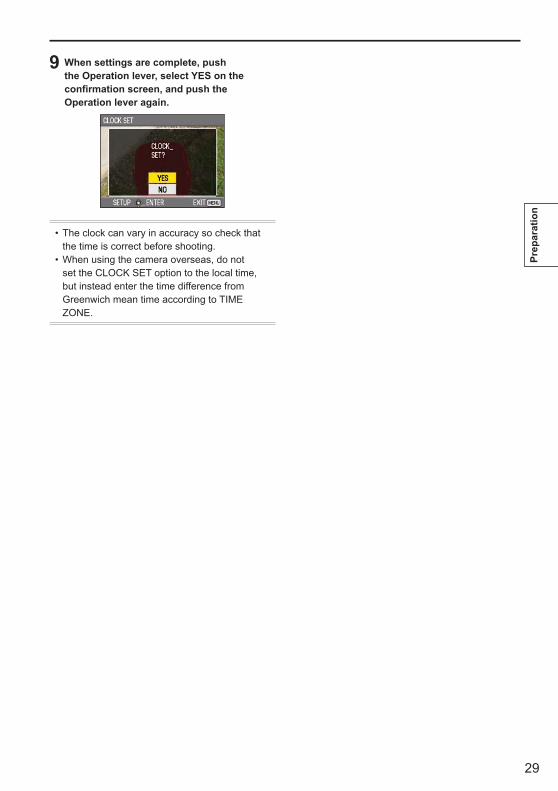
9 When settings are complete, push the Operation lever, select YES on the confirmation screen, and push the Operation lever again.
The clock can vary in accuracy so check that the time is correct before shooting.When using the camera overseas, do not set the CLOCK SET option to the local time, but instead enter the time difference from Greenwich mean time according to TIME ZONE.
•
•
30
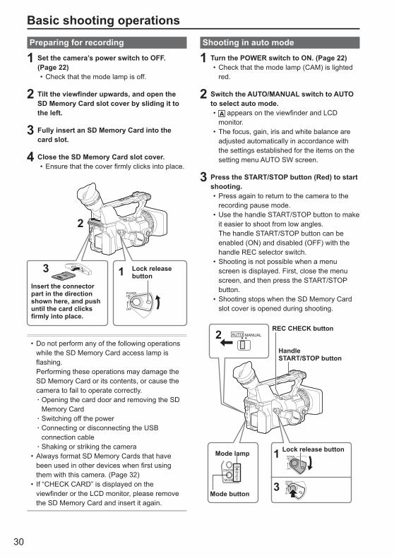
Shooting in auto mode
1 Turn the POWER switch to ON. (Page 22)Check that the mode lamp (CAM) is lighted red.
2 Switch the AUTO/MANUAL switch to AUTO to select auto mode.
appears on the viewfinder and LCD monitor.The focus, gain, iris and white balance are adjusted automatically in accordance with the settings established for the items on the setting menu AUTO SW screen.
3 Press the START/STOP button (Red) to start shooting.
Press again to return to the camera to the recording pause mode. Use the handle START/STOP button to make it easier to shoot from low angles.The handle START/STOP button can be enabled (ON) and disabled (OFF) with the handle REC selector switch.Shooting is not possible when a menu screen is displayed. First, close the menu screen, and then press the START/STOP button.Shooting stops when the SD Memory Card slot cover is opened during shooting.
REC CHECK button
Handle START/STOP button
AUTO MANUAL2
OFF
POWERON
POWERON
OFF
Lock release button1
3PB
Mode button
Mode lamp
•
•
•
•
•
•
•
Preparing for recording
1 Set the camera’s power switch to OFF. (Page 22)
Check that the mode lamp is off.
2 Tilt the viewfinder upwards, and open the SD Memory Card slot cover by sliding it to the left.
3 Fully insert an SD Memory Card into the card slot.
4 Close the SD Memory Card slot cover.Ensure that the cover firmly clicks into place.
2
Insert the connector part in the direction shown here, and push until the card clicks firmly into place.
3 Lock release button
POWERON
OFF
1
Do not perform any of the following operations while the SD Memory Card access lamp is flashing.
Performing these operations may damage the SD Memory Card or its contents, or cause the camera to fail to operate correctly.
Opening the card door and removing the SD Memory CardSwitching off the powerConnecting or disconnecting the USB connection cableShaking or striking the camera
Always format SD Memory Cards that have been used in other devices when first using them with this camera. (Page 32)If “CHECK CARD” is displayed on the viewfinder or the LCD monitor, please remove the SD Memory Card and insert it again.
•
·
··
·•
•
•
•
Basic shooting operations
31
Shoo
ting
The images shot from when shooting starts until it is stopped are recorded as one clip.When recording is paused after a short period, a small amount of time may be required after pressing the START/STOP button to stop recording before writing to the SD Memory Card is terminated.
This means that operations cannot be accepted if the START/STOP button is pressed immediately.The camera will read information from the SD Memory Card immediately after the card is inserted. Press the START/STOP button to begin recording after PAUSE is displayed in the operation status display. (Page 78)The camera’s factory default setting is PH mode 1080/60i recording.(To view current setting status: Page 42)The upper limit for the number of clips which can be recorded on a single SD Memory Card is 900. (However, this number may exceed 900 clips at times such as when shooting immediately after the POWER switch has been set to ON.)
•
•
•
•
•
Checking photos taken (REC CHECK)
Press the REC CHECK button while recording is paused. The last two seconds of video and audio will be played, and the camera will then return to the recording pause mode.
Only the POWER and START/STOP buttons are operable during REC CHECK.The REC CHECK images are also recorded when a device is connected to the camera and backup images have been recorded.The REC CHECK function does not work when PC or PB has been selected as the operation mode.This function also does not work if the REC FORMAT has been changed or if the camera has been set to CAM mode after having switched to PB mode after recording.
•
•
•
•
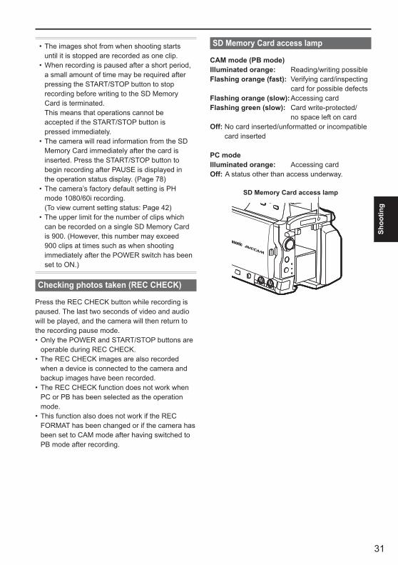
SD Memory Card access lamp
CAM mode (PB mode) Illuminated orange: Reading/writing possibleFlashing orange (fast): Verifying card/inspecting
card for possible defectsFlashing orange (slow): Accessing cardFlashing green (slow): Card write-protected/
no space left on cardOff: No card inserted/unformatted or incompatible
card inserted
PC mode Illuminated orange: Accessing cardOff: A status other than access underway.
SD Memory Card access lamp

32
Basic shooting operations (continued)
Formatting SD Memory Cards
1 Set the camera’s power switch to ON. (Page 22)
2 Press the MENU button.
3 Select CARD FUNCTIONS→CARD FORMAT from the menu.
Select YES when the following screen is displayed. Select NO if you do not wish to format the card.Press the MENU button to close the menu display.
•
•
4 Select YES on the conformation screen.The SD Memory Card will be formatted.
5 Press the MENU button to finish.When an SD Memory Card is formatted, all data recorded on the card will be erased and will not be restorable.Save all important data to your computer.
•
•
SD Memory Card recording times
Total available recording times (approx.) when using SD/SDHC Memory Cards manufactured by Panasonic
SD Memory Card capacity
Recording modePH∗1
(Highest quality mode∗3/ 1920 × 1080 pixels or
1280 × 720 pixels)
HA∗1
(High quality mode/ 1920 × 1080 pixels)
HG∗2
(Standard quality mode/ 1920 × 1080 pixels)
HE∗2
(Long duration mode/ 1440 × 1080 pixels)
512 MB Approx. 2 min Approx. 3 min Approx. 4 min Approx. 10 min1 GB Approx. 5 min Approx. 7 min Approx. 9 min Approx. 21 min2 GB Approx. 10 min Approx. 15 min Approx. 20 min Approx. 45 min4 GB Approx. 21 min Approx. 30 min Approx. 40 min Approx. 90 min6 GB Approx. 33 min Approx. 45 min Approx. 60 min Approx. 135 min8 GB Approx. 45 min Approx. 60 min Approx. 80 min Approx. 180 min
12 GB Approx. 65 min Approx. 90 min Approx. 120 min Approx. 270 min16 GB Approx. 90 min Approx. 120 min Approx. 160 min Approx. 360 min32 GB Approx. 180 min Approx. 240 min Approx. 320 min Approx. 720 min
∗1 Use an SD memory class of SD speed class 4 or above when recording on PH mode or HA mode. Recording cannot be completed on SD Memory Cards of lower speed classes.
∗2 Use an SD memory class of SD speed class 2 or above when recording in HG mode or HE mode.Recording cannot be completed on SD Memory Cards of lower speed classes.
∗3 This is the highest quality mode of this camera.This camera uses the VBR recording system. “VBR” stands for Variable Bit Rate, and it refers to a system in which the bit rate (volume of data per given time period) varies automatically depending on the subject which is being shot. This means that the recording times will be shorter when fast-moving subjects have been recorded.Times displayed include time needed for processing, etc. – actual available recording times will be slightly shorter.The camera is capable of continuous recording for a maximum of 12 hours.Mosaic-like noise may appear on the playback screen under the following shooting conditions:
When there are complex patterns in the backgroundWhen the camera is moved in large motions or when it is moved very quicklyWhen a fast-moving subject has been recorded (and especially when HE has been set as the recording mode)
Repeatedly recording or deleting images over and over again may reduce the recording time on the SD Memory Card. In such cases, format the SD Memory Card using the camera. When a card is formatted, all of its recorded data will be erased, and it will not be subsequently possible to restore this data. Save any valuable data on your PC prior to formatting.
•
•
••
···
•

33
Shoo
ting
Removing SD Memory Card
1 Tilt the viewfinder upwards, and open the SD Memory Card slot cover by sliding it to the left.
Ensure that the SD Memory Card access lamp is not flashing orange before opening the cover.
2 Press the center of the SD Memory Card so that it pops out slightly, and pull the card straight outwards.
SD Memory Card access lamp
2
1
Do not remove the SD Memory Card or switch off the power in the following circumstances. Doing so may damage your SD Memory Card.
1) While the SD Memory Card access lamp is still flashing orange after an SD Memory Card has been inserted.
2) While the SD Memory Card access lamp is flashing such as during recording or during recording finalization.
Protecting SD Memory Cards
Move the write-protect switch on the SD Memory Card to the “LOCK” position to prevent recorded contents being accidentally erased from the card.
32
LOC
K
Write-protect switch
•
•
Repairing SD Memory Cards
Never remove the SD Memory Card or disconnect the battery or DC cord while the SD Memory Card access lamp is flashing, as doing so may damage the SD Memory Card. In the event that the SD Memory Card has been removed while the SD Memory Card access lamp was flashing, or that the battery or DC cord has been disconnected during recording or the recording finalization process, a repair verification screen will be displayed the next time the power is switched on in order to allow errors to be repaired.
Select YES to begin repairing. When repairing is complete, “REPAIR FINISHED” will be displayed, and the camera will switch to the recording paused screen.Select NO to switch directly to the recording paused screen without repairing.
Memory cards cannot be repaired with the camera if NO is selected, but can still be repaired by using the AVCCAM Restorer∗ contents repair software.An SD Memory Card on which an error occurred can be repaired by using either the camera that was used for the shooting, or the AVCCAM Restorer contents repair software.A repair confirmation message may be displayed after inserting an SD Memory Card which has no error, but repair will not be performed even when YES or NO is selected.Repair may take up to 20 minutes or so depending on the places where the errors occurred on the card.Use a battery with an adequate charge or the AC adapter.If the repair operation has failed, “SYSTEM ERROR TURN POWER OFF” will be displayed. In this case, please use the AVCCAM Restorer contents repair software.Depending on the status of the data, it may not be possible to restore all data completely. In this case, it will no longer be possible to play back the clips that were recorded before the power was turned off.Clips with a total recording time of less than 10 seconds may not be able to be repaired.Indexes attached during recording cannot be repaired.
∗ The AVCCAM Restorer can be downloaded from the following website.https://eww.pavc.panasonic.co.jp/pro-av/
•
•
•
•
•
•
•
•
34
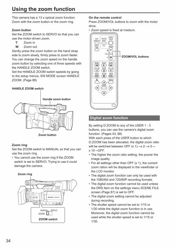
On the remote controlPress ZOOM/VOL buttons to zoom with the motor drive.
Zoom speed is fixed at medium.
ZOOM/VOL buttons
ZOOM
START/STOPPHOTO
SHOTEXT
DISPLAY
DATE/TIME
VOL
PLAY
STOPSKIP SKIP
MENU
ENTER
PAUSE
SEARCH
STILL ADV STILL ADV
SEARCH
Digital zoom function
By setting D.ZOOM to any of the USER 1 - 3 buttons, you can use the camera’s digital zoom function. (Pages 43, 88)With each press of the USER button to which D.ZOOM has been allocated, the digital zoom ratio will be switched between OFF (x 1)→x 2→x 5→x 10→OFF.
The higher the zoom ratio setting, the poorer the image quality.For all settings other than OFF (x 1), the current zoom ration will be displayed in the viewfinder or the LCD monitor.The digital zoom function can only be used with the 1080/60i and 720/60P recording formats.The digital zoom function cannot be used unless the DRS item on the settings menu SCENE FILE screen (Page 87) is set to OFF.The digital zoom setting cannot be adjusted during recording.The shutter speed cannot be set to 1/15 or 1/30 while the digital zoom function is in use. Moreover, the digital zoom function cannot be used while the shutter speed is set to 1/15 or 1/30.
•
•
•
•
•
•
•
Using the zoom functionThis camera has a 13 x optical zoom function.Zoom with the zoom button or the zoom ring.
Zoom buttonSet the ZOOM switch to SERVO so that you can use the motor-driven zoom. T: Zoom in W: Zoom outGently press the zoom button on the hand strap side to zoom slowly, firmly press to zoom faster.You can change the zoom speed on the handle zoom button by selecting one of three speeds with the HANDLE ZOOM switch.Set the HANDLE ZOOM switch speeds by going to the setup menus, SW MODE screen HANDLE ZOOM. (Page 88)
HANDLE ZOOM switch
Handle zoom button
Zoom button
Zoom ringSet the ZOOM switch to MANUAL so that you can use the zoom ring.
You cannot use the zoom ring if the ZOOM switch is set to SERVO. Trying to use it could damage the camera.
Zoom ring
MANUAL
ZOOMSERVO
ZOOM switch
•

35
Shoo
ting
Shooting in progressive modeSelecting 1080/30P or 1080/24P in the REC FORMAT option (Page 91) of the setting menu RECORDING SETUP screen enables shooting in progressive mode.
30P mode: Shoot 30 frames a second in the progressive
mode. For output and recording, the 30-frame-per-
second signal is converted to 60-field-per-second interlace.
This mode gives you high quality images.
AoAeBoBeCoCeDoDeEoEe Fo FeGoGeHoHe Io Ie Jo Je
A B C D E F G H I J30 P
60 i
24P mode: Shoot 24 frames a second in the progressive
mode. The video signal will be recorded natively. However, the external output signal is converted
to a 2:3 format, 60 fps interlaced signal.
A B C D E F G H
AoAeBoBeBoCeCoDeDoDeEoEe FoFe Fo Ge GoHe Ho He
24 P
60 i
Note the following when shooting in progressive mode.
You cannot have a gain of 18 dB.Set the shutter speed to 1/50 (OFF) for best results.There may be a slight delay to the start of recording when you use the 24P mode because 4 frames are recorded at a time.
••
•
36
Shooting in manual modeSet the unit to manual mode when manually adjusting the focus, iris, gain and white balance.
Switching to manual mode
Move the AUTO/MANUAL switch to the MANUAL position to select the manual mode. ( will disappear from the viewfinder or the LCD monitor.)
AUTO/MANUAL switch
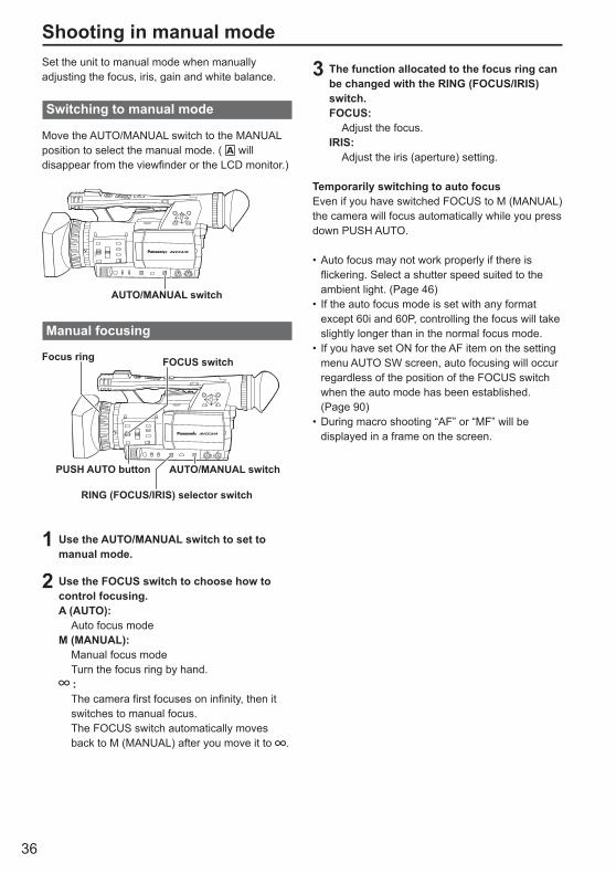
Manual focusing
FOCUS switch
PUSH AUTO button AUTO/MANUAL switch
Focus ring
RING (FOCUS/IRIS) selector switch
1 Use the AUTO/MANUAL switch to set to manual mode.
2 Use the FOCUS switch to choose how to control focusing.A (AUTO): Auto focus modeM (MANUAL): Manual focus mode Turn the focus ring by hand.
: The camera first focuses on infinity, then it
switches to manual focus. The FOCUS switch automatically moves
back to M (MANUAL) after you move it to .
3 The function allocated to the focus ring can be changed with the RING (FOCUS/IRIS) switch.FOCUS: Adjust the focus.IRIS: Adjust the iris (aperture) setting.
Temporarily switching to auto focusEven if you have switched FOCUS to M (MANUAL) the camera will focus automatically while you press down PUSH AUTO.
Auto focus may not work properly if there is flickering. Select a shutter speed suited to the ambient light. (Page 46)If the auto focus mode is set with any format except 60i and 60P, controlling the focus will take slightly longer than in the normal focus mode.If you have set ON for the AF item on the setting menu AUTO SW screen, auto focusing will occur regardless of the position of the FOCUS switch when the auto mode has been established. (Page 90)During macro shooting “AF” or “MF” will be displayed in a frame on the screen.
•
•
•
•
37
Shoo
ting
Iris adjustments
RING (FOCUS/IRIS) switch
IRIS dialIRIS button
1 Use the AUTO/MANUAL switch to set to manual mode. (Page 36)
2 Press the IRIS button to switch how to adjust the aperture of lens.AUTO IRIS: Adjust the iris automatically.MANUAL IRIS: Adjust the iris manually.
3 Turn the IRIS dial to adjust the aperture of lens when in the manual iris mode.
In the auto iris mode, the lens iris can be corrected using this dial.
Set the direction of the IRIS DIAL and aperture control in the setup menus, SW MODE screen, IRIS DIAL. (Page 88)If you have set ON under A.IRIS item on the setting menu AUTO SW screen, auto iris will be forcibly selected when auto mode has been established. (Page 90)The lens aperture can be adjusted in the focus ring by setting the RING (FOCUS/IRIS) switch to IRIS. However, as this will make it impossible to adjust the focus in the focus ring, please set the focus control method to A (AUTO) with the FOCUS switch. (Page 36)
When this camera’s lens aperture is open, the F-value will be F1.6 when the lens zoom is set to maximum wide-angle (W), and F3.0 when set to maximum telescopic (T).While the lens aperture is open, the iris displays on the viewfinder or LCD monitor will show OPEN when the lens zoom is set to maximum wide-angle (W), and F3.0 or OPEN when set to maximum telescopic (T).
•
•
•
•
Using focus assist
Pressing the FOCUS ASSIST button enlarges the center of the screen or displays a frequency distribution graph in the top right of the screen, enabling the focus to be aligned more easily, and therefore particularly useful when using manual focus. The screen display that appears after pressing the FOCUS ASSIST button can be changed with the FOCUS ASSIST setting in the settings menu SW MODE screen. (Page 89)
FOCUS ASSIST button
EXPANDED: The central part of the screen will be enlarged by a factor of about 4 in the vertical direction and by a factor of about 6 in the horizontal direction.“EXPANDED” is displayed on the screen during the expanded display.
The center of the angle of view is shifted slightly from the center of the LCD monitor.
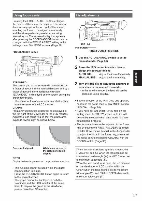
GRAPH: Frequency distribution graph will be displayed in the top right of the viewfinder or the LCD monitor.Adjust the lens focus ring so that the graph area expands toward right as shown below.
Focus not aligned White area moves to the right as focus is aligned
BOTH: Display both enlargement and graph at the same time.
This function cannot be used while the digital zoom function is in use.Press the FOCUS ASSIST button again to return to the original screen.The graph cannot be displayed in both the viewfinder and the LCD monitor at the same time. To display the graph in the viewfinder, please close the LCD monitor.
•
•
•
•

38
Shooting in manual mode (continued)
Adjusting the gain
When the display is dark, increase the gain to brighten the display.
GAIN switch
1 Use the AUTO/MANUAL switch to set to manual mode. (Page 36)
2 Switch the gain with the GAIN switch.L: Set here under normal conditions. (0 dB)M: Increase the gain of the image amplifier.
(The default value is 6 dB.)H: Increase the gain of the image amplifier.
(The default value is 12 dB.)
You can change the M and H gain values using the MID GAIN and HIGH GAIN items on the setting menu SW MODE screen. (Page 88)If the AGC item on the settings menu AUTO SW screen is set to anything other than OFF, the gain setting will be set to automatic during automatic mode, regardless of the position of the GAIN switch. (Page 90)When a slow shutter speed (1/15) has been set, the gain is fixed at 0 dB regardless of the GAIN switch setting. (Page 46)
•
•
•
Light intensity adjustments
Use the ND FILTER switch to change the ND Filter used (filter to change light intensity).
OFF: ND filter is not used.1/4: Cuts light intensity by up to about 1/4.1/16: Cuts light intensity by up to about 1/16.1/64: Cuts light intensity by up to about 1/64.
ND FILTER switch
Adjusting the white balance
In order to reproduce the white accurately, adjust the ratio between the three RGB primary colors. If the white balance is not adjusted properly, not only will the white be reproduced poorly but the color tones of the entire screen will also be downgraded.When you are shooting in manual mode, readjust the white balance whenever lighting conditions change.You can save adjustments and reselect them by setting the WHITE BAL switch to A or B.You can also use the preset values.Use the settings to suit the shooting conditions.
AWB buttonWHITE BAL switch
39
Shoo
ting
White balance adjustments
1 Use the AUTO/MANUAL switch to set to manual mode. (Page 36)
2 Set the shutter speed. (Page 46)
3 Place a white pattern in a location with the same lighting conditions and light source as the subject, then zoom in and fill the whole screen with white.Something white (a white cloth or wall) near the subject can be used instead.
Do not include bright spotlights in your shot.
4 Set the WHITE BAL switch to A or B (whichever one you want to save the adjustment in).
5 Press the AWB button.Adjustment takes a few seconds. (The following messages appear on the screen.)
Message during adjustment
AWB Ach ACTIVE
Message after adjustment
AWB Ach OK
An error message appears on the screen when white balance adjustment is not possible.
Message when adjustment cannot be done
AWB Ach NG
•
•
•
White balance cannot be adjusted if the ATW (Auto Tracking White) function is working.If you have set ON under ATW on the setting menu AUTO SW screen, ATW will be selected when auto mode has been established regardless of the WHITE BAL switch position. (Page 90)Make the necessary adjustments if one of the following error messages appears, then try adjusting the white balance again.
Error messages Adjustments
LOW LIGHT Increase light or increase the gain.
LEVEL OVER Reduce light or decrease the gain.
If the messages repeatedly appear even after trying a number of times, consult your dealer.
•
•
•
•
Using presets
Use this feature when you have no time to make white balance adjustments.
1 Use the AUTO/MANUAL switch to set to manual mode. (Page 36)
2 Set the WHITE BAL switch to PRST.The current white balance value appears.
White balance values 3200 K and 5600 K are preset in the PRST position. Guide to the preset values P3.2K (3200 K): halogen light P5.6K (5600 K): outdoors
3 Press the AWB button.White balance switches between 3200 K and 5600 K.
•
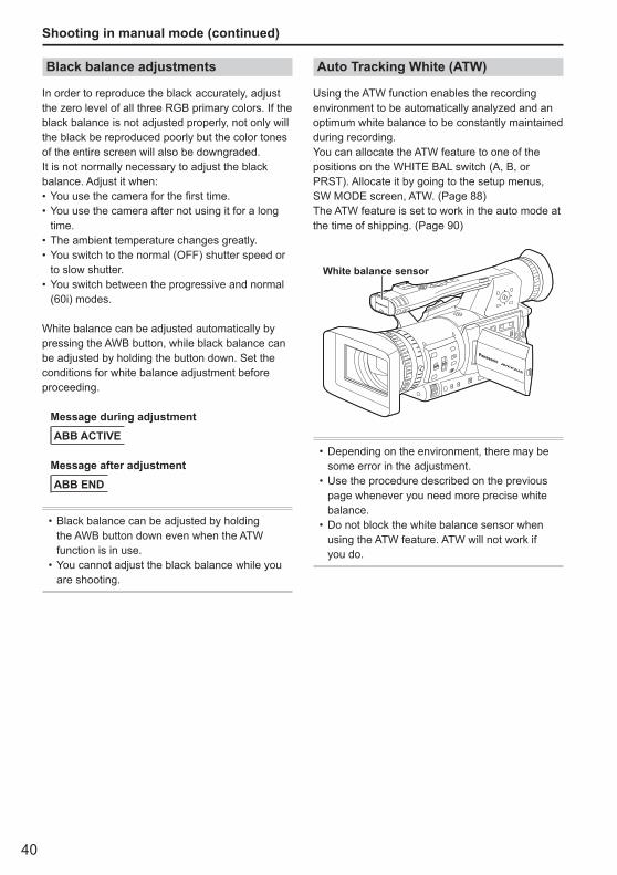
40
Black balance adjustments
In order to reproduce the black accurately, adjust the zero level of all three RGB primary colors. If the black balance is not adjusted properly, not only will the black be reproduced poorly but the color tones of the entire screen will also be downgraded.It is not normally necessary to adjust the black balance. Adjust it when:
You use the camera for the first time.You use the camera after not using it for a long time.The ambient temperature changes greatly.You switch to the normal (OFF) shutter speed or to slow shutter.You switch between the progressive and normal (60i) modes.
White balance can be adjusted automatically by pressing the AWB button, while black balance can be adjusted by holding the button down. Set the conditions for white balance adjustment before proceeding.
Message during adjustment
ABB ACTIVE
Message after adjustment
ABB END
Black balance can be adjusted by holding the AWB button down even when the ATW function is in use.You cannot adjust the black balance while you are shooting.
•
•
••
••
•
Auto Tracking White (ATW)
Using the ATW function enables the recording environment to be automatically analyzed and an optimum white balance to be constantly maintained during recording.You can allocate the ATW feature to one of the positions on the WHITE BAL switch (A, B, or PRST). Allocate it by going to the setup menus, SW MODE screen, ATW. (Page 88)The ATW feature is set to work in the auto mode at the time of shipping. (Page 90)
White balance sensor
Depending on the environment, there may be some error in the adjustment.Use the procedure described on the previous page whenever you need more precise white balance.Do not block the white balance sensor when using the ATW feature. ATW will not work if you do.
•
•
•
Shooting in manual mode (continued)
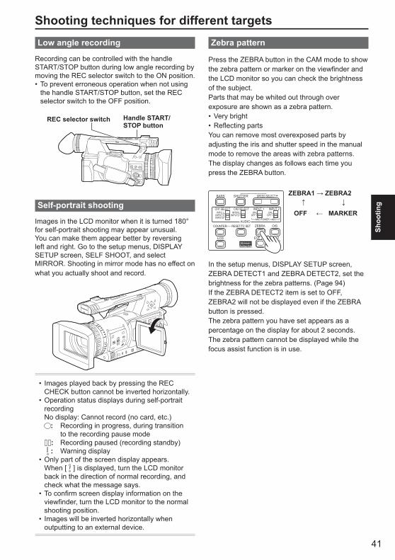
41
Shoo
ting
Shooting techniques for different targetsLow angle recording
Recording can be controlled with the handle START/STOP button during low angle recording by moving the REC selector switch to the ON position.
To prevent erroneous operation when not using the handle START/STOP button, set the REC selector switch to the OFF position.
Handle START/STOP button
REC selector switch
Self-portrait shooting
Images in the LCD monitor when it is turned 180° for self-portrait shooting may appear unusual.You can make them appear better by reversing left and right. Go to the setup menus, DISPLAY SETUP screen, SELF SHOOT, and select MIRROR. Shooting in mirror mode has no effect on what you actually shoot and record.
Images played back by pressing the REC CHECK button cannot be inverted horizontally.Operation status displays during self-portrait recordingNo display: Cannot record (no card, etc.)
: Recording in progress, during transition to the recording pause mode
: Recording paused (recording standby) : Warning display
Only part of the screen display appears. When [ ] is displayed, turn the LCD monitor back in the direction of normal recording, and check what the message says.To confirm screen display information on the viewfinder, turn the LCD monitor to the normal shooting position.Images will be inverted horizontally when outputting to an external device.
•
•
•
•
•
•
Zebra pattern
Press the ZEBRA button in the CAM mode to show the zebra pattern or marker on the viewfinder and the LCD monitor so you can check the brightness of the subject. Parts that may be whited out through over exposure are shown as a zebra pattern.
Very brightReflecting parts
You can remove most overexposed parts by adjusting the iris and shutter speed in the manual mode to remove the areas with zebra patterns.The display changes as follows each time you press the ZEBRA button.
BARS
LCD
ZEBRA OIS
EVF DTL WFM
CH1 SELECT CH2 SELECT INPUT 1 INPUT 2
SHUTTER
COUNTER RESET/TC SETAUDIO
SPEED SELECT
INT(L)INPUT1INPUT2
INT(R)INPUT2
ON
MIC POWER +48V
OFFON
OFF
ZEBRA1 → ZEBRA2 ↑ ↓ OFF ← MARKER
In the setup menus, DISPLAY SETUP screen, ZEBRA DETECT1 and ZEBRA DETECT2, set the brightness for the zebra patterns. (Page 94)If the ZEBRA DETECT2 item is set to OFF, ZEBRA2 will not be displayed even if the ZEBRA button is pressed.The zebra pattern you have set appears as a percentage on the display for about 2 seconds.The zebra pattern cannot be displayed while the focus assist function is in use.
••
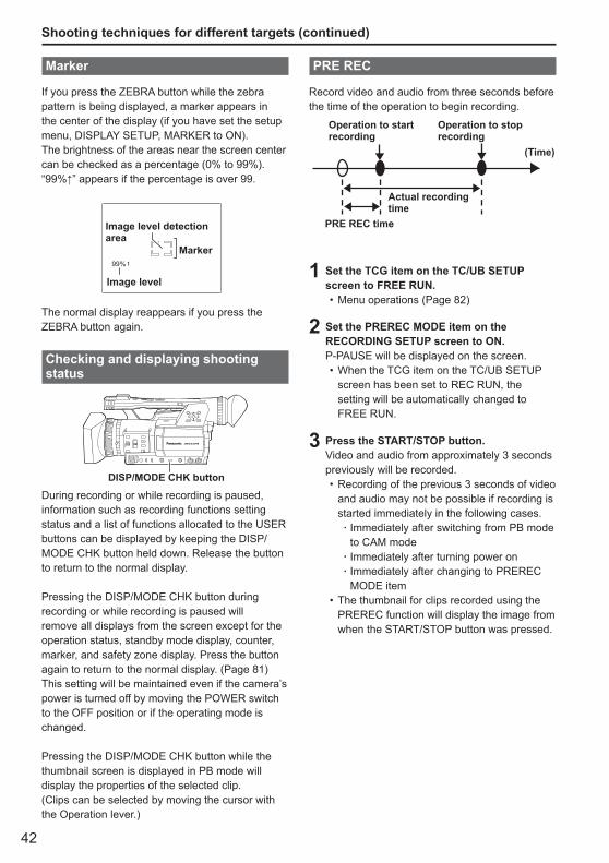
42
Marker
If you press the ZEBRA button while the zebra pattern is being displayed, a marker appears in the center of the display (if you have set the setup menu, DISPLAY SETUP, MARKER to ON). The brightness of the areas near the screen center can be checked as a percentage (0% to 99%).“99%↑” appears if the percentage is over 99.
99%
Image level detection area
Image level
Marker
The normal display reappears if you press the ZEBRA button again.
Checking and displaying shooting status
DISP/MODE CHK button
During recording or while recording is paused, information such as recording functions setting status and a list of functions allocated to the USER buttons can be displayed by keeping the DISP/MODE CHK button held down. Release the button to return to the normal display.
Pressing the DISP/MODE CHK button during recording or while recording is paused will remove all displays from the screen except for the operation status, standby mode display, counter, marker, and safety zone display. Press the button again to return to the normal display. (Page 81)This setting will be maintained even if the camera’s power is turned off by moving the POWER switch to the OFF position or if the operating mode is changed.
Pressing the DISP/MODE CHK button while the thumbnail screen is displayed in PB mode will display the properties of the selected clip. (Clips can be selected by moving the cursor with the Operation lever.)
Shooting techniques for different targets (continued)
PRE REC
Record video and audio from three seconds before the time of the operation to begin recording.
Operation to start recording
Operation to stop recording
Actual recording time
PRE REC time
(Time)
1 Set the TCG item on the TC/UB SETUP screen to FREE RUN.
Menu operations (Page 82)
2 Set the PREREC MODE item on the RECORDING SETUP screen to ON.P-PAUSE will be displayed on the screen.
When the TCG item on the TC/UB SETUP screen has been set to REC RUN, the setting will be automatically changed to FREE RUN.
3 Press the START/STOP button.Video and audio from approximately 3 seconds previously will be recorded.
Recording of the previous 3 seconds of video and audio may not be possible if recording is started immediately in the following cases.
Immediately after switching from PB mode to CAM modeImmediately after turning power onImmediately after changing to PREREC MODE item
The thumbnail for clips recorded using the PREREC function will display the image from when the START/STOP button was pressed.
•
•
•
·
··
•
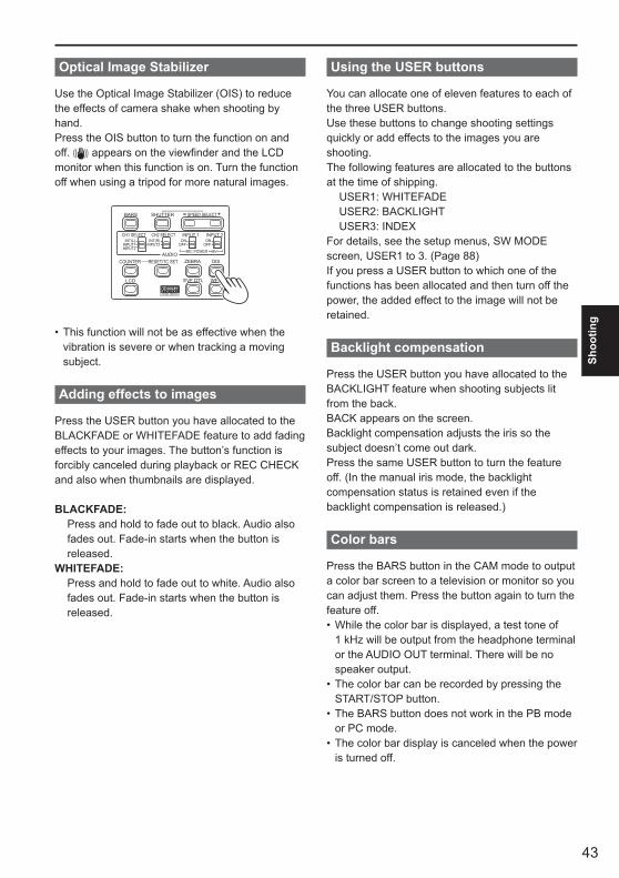
43
Shoo
ting
Optical Image Stabilizer
Use the Optical Image Stabilizer (OIS) to reduce the effects of camera shake when shooting by hand.Press the OIS button to turn the function on and off. appears on the viewfinder and the LCD monitor when this function is on. Turn the function off when using a tripod for more natural images.
BARS
LCD
ZEBRA OIS
EVF DTL WFM
CH1 SELECT CH2 SELECT INPUT 1 INPUT 2
SHUTTER
COUNTER RESET/TC SETAUDIO
SPEED SELECT
INT(L)INPUT1INPUT2
INT(R)INPUT2
ON
MIC POWER +48V
OFFON
OFF
This function will not be as effective when the vibration is severe or when tracking a moving subject.
Adding effects to images
Press the USER button you have allocated to the BLACKFADE or WHITEFADE feature to add fading effects to your images. The button’s function is forcibly canceled during playback or REC CHECK and also when thumbnails are displayed.
BLACKFADE: Press and hold to fade out to black. Audio also
fades out. Fade-in starts when the button is released.
WHITEFADE: Press and hold to fade out to white. Audio also
fades out. Fade-in starts when the button is released.
•
Using the USER buttons
You can allocate one of eleven features to each of the three USER buttons. Use these buttons to change shooting settings quickly or add effects to the images you are shooting. The following features are allocated to the buttons at the time of shipping. USER1: WHITEFADE USER2: BACKLIGHT USER3: INDEXFor details, see the setup menus, SW MODE screen, USER1 to 3. (Page 88)If you press a USER button to which one of the functions has been allocated and then turn off the power, the added effect to the image will not be retained.
Backlight compensation
Press the USER button you have allocated to the BACKLIGHT feature when shooting subjects lit from the back.BACK appears on the screen. Backlight compensation adjusts the iris so the subject doesn’t come out dark.Press the same USER button to turn the feature off. (In the manual iris mode, the backlight compensation status is retained even if the backlight compensation is released.)
Color bars
Press the BARS button in the CAM mode to output a color bar screen to a television or monitor so you can adjust them. Press the button again to turn the feature off.
While the color bar is displayed, a test tone of 1 kHz will be output from the headphone terminal or the AUDIO OUT terminal. There will be no speaker output.The color bar can be recorded by pressing the START/STOP button.The BARS button does not work in the PB mode or PC mode.The color bar display is canceled when the power is turned off.
•
•
•
•
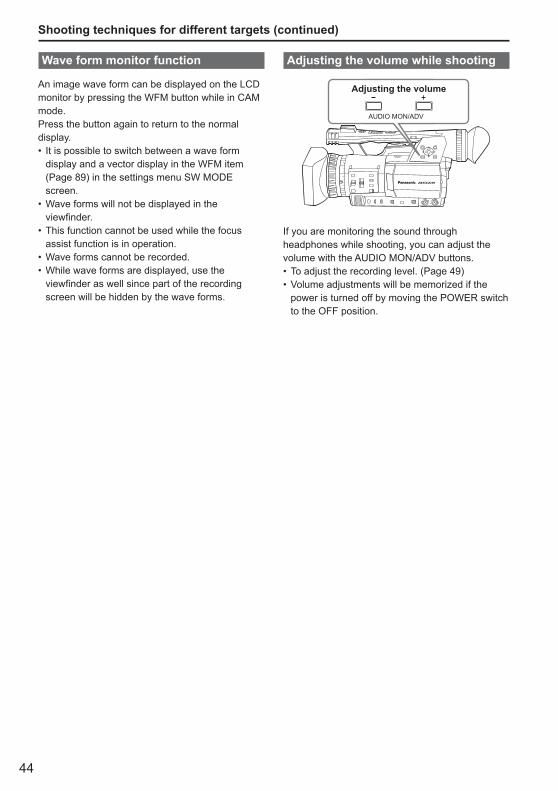
44
Shooting techniques for different targets (continued)
Wave form monitor function
An image wave form can be displayed on the LCD monitor by pressing the WFM button while in CAM mode.Press the button again to return to the normal display.
It is possible to switch between a wave form display and a vector display in the WFM item (Page 89) in the settings menu SW MODE screen.Wave forms will not be displayed in the viewfinder.This function cannot be used while the focus assist function is in operation.Wave forms cannot be recorded.While wave forms are displayed, use the viewfinder as well since part of the recording screen will be hidden by the wave forms.
•
•
•
••
Adjusting the volume while shooting
����
AUDIO MON/ADV
Adjusting the volume
AUDIO MON/ADV
If you are monitoring the sound through headphones while shooting, you can adjust the volume with the AUDIO MON/ADV buttons.
To adjust the recording level. (Page 49)Volume adjustments will be memorized if the power is turned off by moving the POWER switch to the OFF position.
••
45
Shoo
ting
Shot mark function
The marks attached to the thumbnails of clips are called shot marks. On the thumbnail screen monitor you can select only those clips with a shot mark and display them or play them back.During recording, when you press the USER button to which the SHOT MARK function has been allocated, MARK ON appears in the LCD monitor or the viewfinder, and a shot mark is set for the thumbnail of the clip being recorded. If you press the button again, the shot mark is released.You can also set or release the shot marks by performing the thumbnail operations for clips. (Page 62)However, note that you cannot set or release shot marks during playback.
INVALID appears when you cannot set or release shot marks.
Index recording
This function allows you to add an index at a certain point of a clip during the recording or playback.Press the USER button allocated to the INDEX function during recording to record an index signal at this point of the clip. (Pages 43, 89)Indexes may also be added during playback, and it is also possible to select only clips with indexes for display or playback. (Pages 65, 66)
Up to 100 indexes can be recorded for one clip.When the number of indexes exceeds 100, INVALID is displayed, and no further indexes can be added even when the steps for adding indexes are taken.When repeatedly adding indexes, leave a gap of at least one second between adding one index and the next. If indexes are added with a gap of less than one second between them, only the first operation will be valid.
•
•
•
•
Time stamp function
The date and time of recording can be recorded to video images.Select ON in the TIME STAMP item on the settings menu RECORDING SETUP screen.When the TIME STAMP function is ON, the letter R will be displayed in front of the date and time display in the viewfinder and the LCD monitor.
The letter R display itself will not be recorded to the video.The size and position of the time and date characters recorded to the image will vary depending on the recording format.The size and position of the timestamp characters in external output displays may vary from the displays in the LCD monitor or viewfinder.The recorded time and date display will follow the settings made in the DATE/TIME item on the DISPLAY SETUP screen. No time and date display will be recorded if this item is set to OFF.To avoid date and time displays overlapping when clips with timestamps recorded are played with this camera, please set the DATE/TIME item on the DISPLAY SETUP screen to OFF.
LAST CLIP function
The most recently recorded clip can be deleted at the touch of a button by allocating the LAST CLIP function to any of the USER 1 - 3 buttons.Press the USER button allocated for the LAST CLIP function to display YES/NO on the screen.Select YES to delete the most recently recorded clip.
Select NO not to delete the clip.If the camera has been switched to PB mode or the recording format has been changed since recording was completed, clips cannot be deleted even if the button is pressed. Clips also cannot be deleted if the power has been switched off and back on again.Clips cannot be deleted even if the button is pressed if the memory card has been removed and reinserted since recording was completed.
•
•
•
•
•
••
•
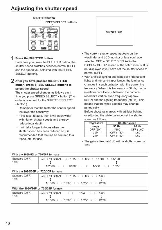
46
BARS
LCD
ZEBRA OIS
EVF DTL WFM
CH1 SELECT CH2 SELECT INPUT 1 INPUT 2
SHUTTER
COUNTER RESET/TC SETAUDIO
SPEED SELECT
INT(L)INPUT1INPUT2
INT(R)INPUT2
ON
MIC POWER +48V
OFFON
OFF
SHUTTER buttonSPEED SELECT buttons
1 Press the SHUTTER button.Each time you press the SHUTTER button, the shutter speed switches between normal (OFF) and the speed you selected with the SPEED SELECT buttons.
2 After you have pressed the SHUTTER button, press SPEED SELECT buttons to select the shutter speed.The shutter speed changes as follows each time you press SPEED SELECT + button (The order is reversed for the SHUTTER SELECT - button.)
Remember that the faster the shutter speed, the lower the sensitivity.If iris is set to auto, then it will open wider with higher shutter speeds and thereby reduce focal depth.It will take longer to focus when the shutter speed has been reduced so it is recommended that the unit be secured to a tripod, etc. for use.
•
•
•
SHUTTER 1/60
The current shutter speed appears on the viewfinder and LCD monitor unless you have selected OFF in OTHER DISPLAY in the DISPLAY SETUP screen of the setup menus. It is not displayed if you have set the shutter speed to normal (OFF).With artificial lighting and especially fluorescent lights and mercury-vapor lamps, the luminance changes in synchronization with the power line frequency. When this frequency is 50 Hz, mutual interference will occur between the camera-recorder’s vertical sync frequency (approx. 60 Hz) and the lighting frequency (50 Hz). This means that the white balance may change periodically.
Before shooting in areas with artificial lighting or adjusting the white balance, set the shutter speed as follows.
Progressive mode
Shutter speed50 Hz 60 Hz
OFF (60i) 1/100 OFF (1/60)30P OFF (1/50) 1/6024P OFF (1/50) 1/60
The gain is fixed at 0 dB with a shutter speed of 1/15.
•
•
•
Adjusting the shutter speed
With the 1080/60i or 720/60P formatsStandard (OFF)1/60
SYNCRO SCAN 1/15 1/30 1/100 1/120
1/2000 1/1000 1/500 1/250
With the 1080/30P or 720/30P formatsStandard (OFF)1/50
SYNCRO SCAN 1/15 1/30 1/60
1/1000 1/500 1/250 1/120
With the 1080/24P or 720/24P formatsStandard (OFF)1/50
SYNCRO SCAN 1/24 1/60
1/1000 1/500 1/250 1/120
47
Shoo
ting
Synchro scan
Set the shutter speed of the synchro scan (used when shooting a television or computer monitor) in the setup menus, SCENE FILE screen, SYNCRO SCAN. (Page 86)
Adjust the shutter speed to match the frequency of the television or computer monitor to minimize the horizontal noise that appears when shooting such subjects.By switching to progressive mode you can also shoot PAL system television screens.If the SYNCRO SCAN item is displayed in grey, it cannot be used with the current recording format. This function will only operate for preset values for each recording format, as listed below.
60i/60P mode: 1/60 30P mode: 1/30
You can change the progressive mode in the setup menu with REC FORMAT in the RECORDING SETUP screen. (Page 91)
•
•
•
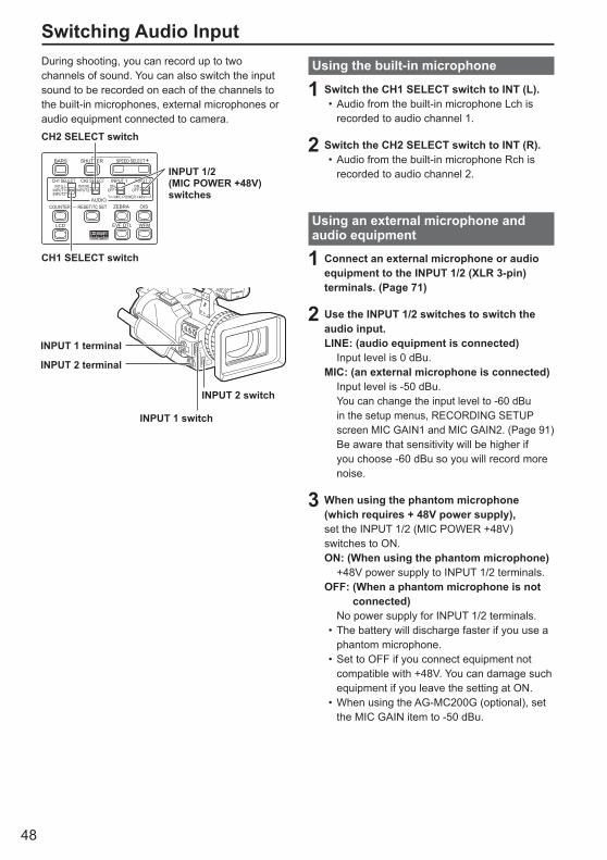
48
During shooting, you can record up to two channels of sound. You can also switch the input sound to be recorded on each of the channels to the built-in microphones, external microphones or audio equipment connected to camera.
BARS
LCD
ZEBRA OIS
EVF DTL WFM
CH1 SELECT CH2 SELECT INPUT 1 INPUT 2
SHUTTER
COUNTER RESET/TC SETAUDIO
SPEED SELECT
INT(L)INPUT1INPUT2
INT(R)INPUT2
ON
MIC POWER +48V
OFFON
OFF
CH2 SELECT switch
CH1 SELECT switch
INPUT 1/2 (MIC POWER +48V) switches
INPUT 2 switch
INPUT 1 switch
INPUT 1 terminal
INPUT 2 terminal
Switching Audio InputUsing the built-in microphone
1 Switch the CH1 SELECT switch to INT (L).Audio from the built-in microphone Lch is recorded to audio channel 1.
2 Switch the CH2 SELECT switch to INT (R).Audio from the built-in microphone Rch is recorded to audio channel 2.
Using an external microphone and audio equipment
1 Connect an external microphone or audio equipment to the INPUT 1/2 (XLR 3-pin) terminals. (Page 71)
2 Use the INPUT 1/2 switches to switch the audio input.LINE: (audio equipment is connected) Input level is 0 dBu.MIC: (an external microphone is connected) Input level is -50 dBu.
You can change the input level to -60 dBu in the setup menus, RECORDING SETUP screen MIC GAIN1 and MIC GAIN2. (Page 91)Be aware that sensitivity will be higher if you choose -60 dBu so you will record more noise.
3 When using the phantom microphone (which requires + 48V power supply),set the INPUT 1/2 (MIC POWER +48V) switches to ON.ON: (When using the phantom microphone) +48V power supply to INPUT 1/2 terminals.OFF: (When a phantom microphone is not
connected) No power supply for INPUT 1/2 terminals.
The battery will discharge faster if you use a phantom microphone.Set to OFF if you connect equipment not compatible with +48V. You can damage such equipment if you leave the setting at ON.When using the AG-MC200G (optional), set the MIC GAIN item to -50 dBu.
•
•
•
•
•
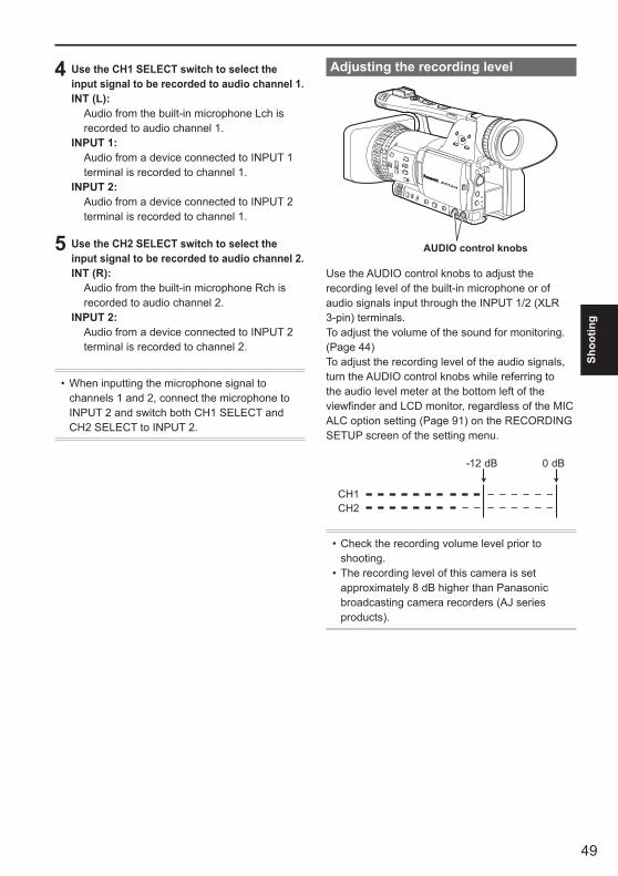
49
Shoo
ting
Adjusting the recording level
AUDIO control knobs
Use the AUDIO control knobs to adjust the recording level of the built-in microphone or of audio signals input through the INPUT 1/2 (XLR 3-pin) terminals. To adjust the volume of the sound for monitoring. (Page 44)To adjust the recording level of the audio signals, turn the AUDIO control knobs while referring to the audio level meter at the bottom left of the viewfinder and LCD monitor, regardless of the MIC ALC option setting (Page 91) on the RECORDING SETUP screen of the setting menu.
Check the recording volume level prior to shooting.The recording level of this camera is set approximately 8 dB higher than Panasonic broadcasting camera recorders (AJ series products).
•
•
4 Use the CH1 SELECT switch to select the input signal to be recorded to audio channel 1.INT (L): Audio from the built-in microphone Lch is
recorded to audio channel 1.INPUT 1: Audio from a device connected to INPUT 1
terminal is recorded to channel 1.INPUT 2: Audio from a device connected to INPUT 2
terminal is recorded to channel 1.
5 Use the CH2 SELECT switch to select the input signal to be recorded to audio channel 2.INT (R): Audio from the built-in microphone Rch is
recorded to audio channel 2.INPUT 2: Audio from a device connected to INPUT 2
terminal is recorded to channel 2.
When inputting the microphone signal to channels 1 and 2, connect the microphone to INPUT 2 and switch both CH1 SELECT and CH2 SELECT to INPUT 2.
•

50
Using scene filesThe settings according to the variety of shooting circumstances are stored in each position of SCENE FILE dial.When shooting, you can retrieve the necessary file instantly using SCENE FILE dial.
SCENE FILE dial
When the camera-recorder is shipped from the factory, the following files are stored.
F1: SCENE File suitable for normal shooting.F2: SCENE FLUO. File suitable for shooting under fluorescent
lights, ie. indoors.F3: SCENE SPARK File suitable for shooting with fuller variations
of resolution, coloring and contrast.F4: SCENE B-STR File for broadening the contrast of dark parts,
such as when shooting sunsets.F5: SCENE CINE V File suitable for shooting movie-like scenes
where the contrast is to be emphasized. (The recording format remains unchanged even when the scene file is changed. It must be set using the REC FORMAT item on the RECORDING SETUP screen. (Page 91))
F6: SCENE CINE D File suitable for shooting movie-like
scenes where the dynamic range is to be emphasized. (The recording format remains unchanged even when the scene file is changed. It must be set using the REC FORMAT item on the RECORDING SETUP screen. (Page 91))
Changing scene file settings
The setting value of the scene file can be changed. Also you can save the changed scene file to each position of the SCENE FILE dial.
Example: Change the name of the scene file.
1 Set the POWER switch to ON.
2 Turn the SCENE FILE dial, then select the scene file to be changed.
3 In the setup menus, select the SCENE FILE screen.
For menu operation (Page 82)Operations may also be performed using buttons on the remote control that correspond to those on the camera. For details, see “Description of parts (Remote control) ”. (Page 18)
4 Tilt the Operation lever in the directions and select the NAME EDIT item.
5 Push the Operation lever (or tilt in the direction), tilt in the direction to select YES, and push the Operation lever again.
••

51
Shoo
ting
6 Set a 6-character filename with the Operation lever when the following screen is displayed.Set the same as user information. (Page 58)
Characters that can be set Space, A to Z, 0 to 9, : ; < = > ? @ [ ] ^_-./
If the RESET/TC SET button is pressed when the filename has been set, the characters are cleared.
7 After you finish setting the filename, push the Operation lever.
8 Select YES on the confirmation screen.Selecting YES will close the NAME EDIT screen and confirm all changes.Once confirmed, all changed names and values will be saved even if the power is switched off or the scene dial is moved.
•
•
•

52
Saving scene files and other settings on SD Memory Cards
4 Push the Operation lever again, select YES when the following screen is displayed, and push the Operation lever.
In the following example, TITLE001 is the filename. (To change the filename, see the description below.)
5 Press the MENU button to exit the menu mode.
To read files1) Select READ in step 2 and push the Operation
lever.2) Select the file number and push the Operation
lever.3) Select YES on the confirmation screen. READ COMPLETED will be displayed when
reading is complete.
To add titles to files1) Go through steps 1 - 3.2) Tilt the Operation lever in the directions to
select characters, and tilt in the direction to move to the next character.The following characters may be inputted.(Space), A-Z, 0-9, : ; < = > ? @ [ ] ^ _ - . /
3) Push the Operation lever when all characters have been inputted.
4) Select YES on the confirmation screen.
If WRITE NG WRITE PROTECT appears, release the protected status of the SD Memory Card.If WRITE NG CANNOT ACCESS appears, quit all other operations (such as playback) before proceeding.
•
•
•
You can save up to four scene file settings or other settings as files on an SD Memory Card, and you can also load them from the card.
In the case of the scene files, the current settings are automatically saved in the unit, and the saved data is written on an SD Memory Card. When data has been read from an SD Memory Card, the current settings are rewritten at the same time as the data saved inside the unit.The data in all the scene files, F1 to F6, is rewritten.
If you have saved a scene file
1 Set the unit’s POWER switch to ON.
2 Select CARD READ/WRITE on the settings menu SCENE FILE screen, select WRITE, and push the Operation lever.For all other settings, select USER FILE.
For menu operations (Page 82) Operations may also be performed using buttons on the remote control that correspond to those on the camera. For details, see “Description of parts (Remote control)”. (Page 18)
3 Tilt the Operation lever in the directions, select the file number (1 - 4), and push the Operation lever.
•
•
••
53
Shoo
ting
You can add the video and audio systems, name of the videographer, shooting location, text memos and other information to the video data you have recorded on the SD Memory Card. This data is called the clip metadata.(Display method: Page 68)
There are two kinds of clip metadata: the data that is recorded automatically during shooting, and the data in the metadata upload file created on the SD Memory Card which is loaded in the unit. (Loading method: Next page)
What the clip metadata consists of
You can set the items underlined below by loading the metadata upload file on the SD Memory Card. All other items are set automatically during shooting.
GLOBAL CLIP ID: This indicates the global clip ID that shows the
shooting status of the clip.USER CLIP NAME : This indicates the name of the clip that the user
has set.∗1
VIDEO & AUDIO: This indicates the recorded image’s FRAME
RATE, RESOLUTION, PULL DOWN system and AUDIO.
ACCESS: This indicates the CREATOR (name of the
person recording), CREATION DATE (recording date), LAST UPDATE DATE (date on which the data was last updated) and LAST UPDATE PERSON (the person who last updated the data).
DEVICE: This indicates the MANUFACTURER
(manufacturer of the equipment), SERIAL NO. (serial number of the equipment) and MODEL NAME (equipment model name: AG-HMC150).
SHOOT: This indicates the SHOOTER (name of the
videographer) and the PLACE NAME (name of location).
LOCATION: This indicates ALTITUDE, LONGITUDE,
LATITUDE, and SOURCE (altitude, longitude, latitude, information source).
SCENARIO:∗2
This indicates the PROGRAM NAME, SCENE NO. and TAKE NO.NEWS 1: This indicates the REPORTER (name of the
reporter) and PURPOSE (purpose of data collection).
NEWS 2: This indicates the OBJECT (target of data
collection).MEMO:∗3
This indicates the PERSON (name of the person who recorded the text memo) and TEXT (contents of memo).
∗1 If there is no information in the metadata upload file, consecutive five-digit numbers will be applied to the clips in the order that they were recorded, with the first clip to be recorded being given the number 0. The USER CLIP NAME recording method is selectable. Please refer to the page 54.
∗2 When SCENARIO is to be input, you must input the PROGRAM NAME. You cannot input the SCENE NO. and TAKE NO. only.
∗3 When MEMO is to be input, you must input TEXT. You cannot input PERSON only.
Only printable ASCII characters can be displayed by this unit.Due to the limitations imposed by this unit on the number of characters which can be displayed, not all the data can be displayed. (This does not mean that the data which is not displayed has been deleted.) Use an AVCCAM viewer or other program to check all the data.Metadata can be produced with AVCCAM Viewer.
•
•
•
Clip metadata
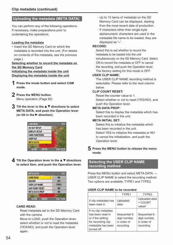
54
Uploading the metadata (META DATA)
You can perform any of the following operations. If necessary, make preparations prior to undertaking the operations.
Loading the metadataInsert the SD Memory Card on which the metadata is recorded into the unit. (For details on contents of the metadata, see the previous page.)
Selecting whether to record the metadata on the SD Memory CardInitializing the metadata inside the unitDisplaying the metadata inside the unit
1 Press the mode button and select CAM mode.
2 Press the MENU button.Menu operation (Page 82)
3 Tilt the lever in the directions to select META DATA, and push the Operation lever (or tilt in the direction).
4 Tilt the Operation lever in the directions to select item, and push the Operation lever.
CARD READ: Read metadata set to the SD Memory Card
with the camera.Move to LOAD, push the Operation lever, select whether or not to read the metadata (YES/NO), and push the Operation lever again.
•
Up to 10 items of metadata on the SD Memory Card can be displayed, starting from the most recent date of production.If characters other than single-byte alphanumeric characters are used in the metadata file name to be loaded, they are displayed as “∗”.
RECORD: Select this to set whether to record the
metadata to be loaded into the unit simultaneously on the SD Memory Card. Select ON to record the metadata or OFF to cancel the recording, and push the Operation lever. The factory setting for this mode is OFF.
USER CLIP NAME: The USER CLIP NAME recording method is
selectable. Please refer to the next column below.
CLIP COUNT RESET: Reset the counter value to 1. Select whether or not to reset (YES/NO), and
push the Operation lever.META DATA PROP: Select this to display the metadata which has
been recorded in the unit.META INITIAL SET: Select this to initialize the metadata which
has been recorded in the unit. Select YES to initialize the metadata or NO to cancel the initialization, and push the Operation lever.
5 Press the MENU button to release the menu mode.
Selecting the USER CLIP NAME recording method
Press the MENU button and select META DATA → USER CLIP NAME to select the recording method. Two options are available: TYPE1 and TYPE2.
USER CLIP NAME to be recordedTYPE1 TYPE2
If clip metadata has been read in
Uploaded data
Uploaded data + COUNT value∗
If no clip metadata has been read in or if the setting for recording clip metadata has been turned off
Sequential 5-digit number, in order of recording
Sequential 5-digit number, in order of recording
·
·
Clip metadata (continued)
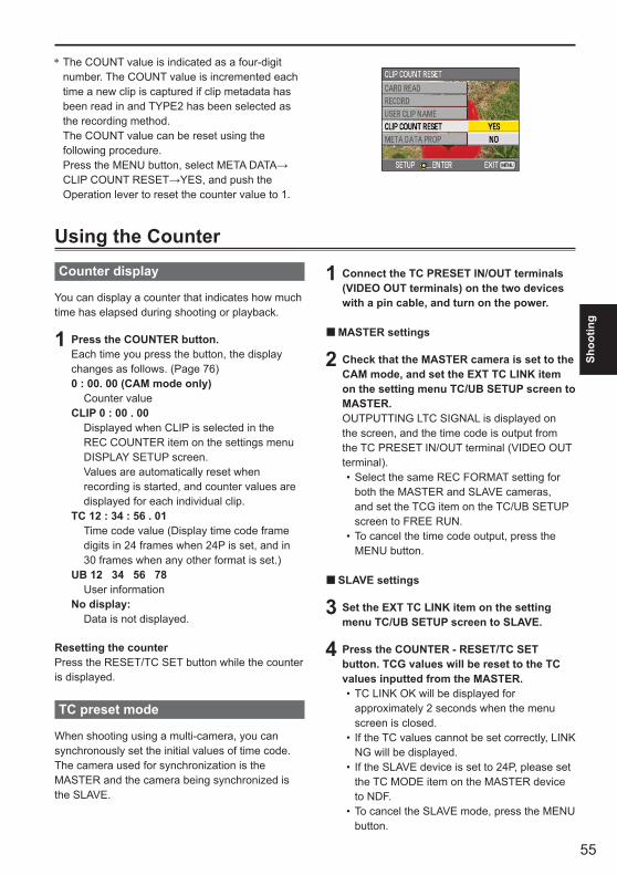
55
Shoo
ting
Using the CounterCounter display
You can display a counter that indicates how much time has elapsed during shooting or playback.
1 Press the COUNTER button.Each time you press the button, the display changes as follows. (Page 76)0 : 00. 00 (CAM mode only) Counter valueCLIP 0 : 00 . 00 Displayed when CLIP is selected in the
REC COUNTER item on the settings menu DISPLAY SETUP screen.
Values are automatically reset when recording is started, and counter values are displayed for each individual clip.
TC 12 : 34 : 56 . 01 Time code value (Display time code frame
digits in 24 frames when 24P is set, and in 30 frames when any other format is set.)
UB 12 34 56 78 User informationNo display: Data is not displayed.
Resetting the counterPress the RESET/TC SET button while the counter is displayed.
TC preset mode
When shooting using a multi-camera, you can synchronously set the initial values of time code. The camera used for synchronization is the MASTER and the camera being synchronized is the SLAVE.
1 Connect the TC PRESET IN/OUT terminals (VIDEO OUT terminals) on the two devices with a pin cable, and turn on the power.
MASTER settings
2 Check that the MASTER camera is set to the CAM mode, and set the EXT TC LINK item on the setting menu TC/UB SETUP screen to MASTER.OUTPUTTING LTC SIGNAL is displayed on the screen, and the time code is output from the TC PRESET IN/OUT terminal (VIDEO OUT terminal).
Select the same REC FORMAT setting for both the MASTER and SLAVE cameras, and set the TCG item on the TC/UB SETUP screen to FREE RUN.To cancel the time code output, press the MENU button.
SLAVE settings
3 Set the EXT TC LINK item on the setting menu TC/UB SETUP screen to SLAVE.
4 Press the COUNTER - RESET/TC SET button. TCG values will be reset to the TC values inputted from the MASTER.
TC LINK OK will be displayed for approximately 2 seconds when the menu screen is closed.If the TC values cannot be set correctly, LINK NG will be displayed.If the SLAVE device is set to 24P, please set the TC MODE item on the MASTER device to NDF.To cancel the SLAVE mode, press the MENU button.
■
•
•
■
•
•
•
•
∗ The COUNT value is indicated as a four-digit number. The COUNT value is incremented each time a new clip is captured if clip metadata has been read in and TYPE2 has been selected as the recording method. The COUNT value can be reset using the following procedure.Press the MENU button, select META DATA→CLIP COUNT RESET→YES, and push the Operation lever to reset the counter value to 1.
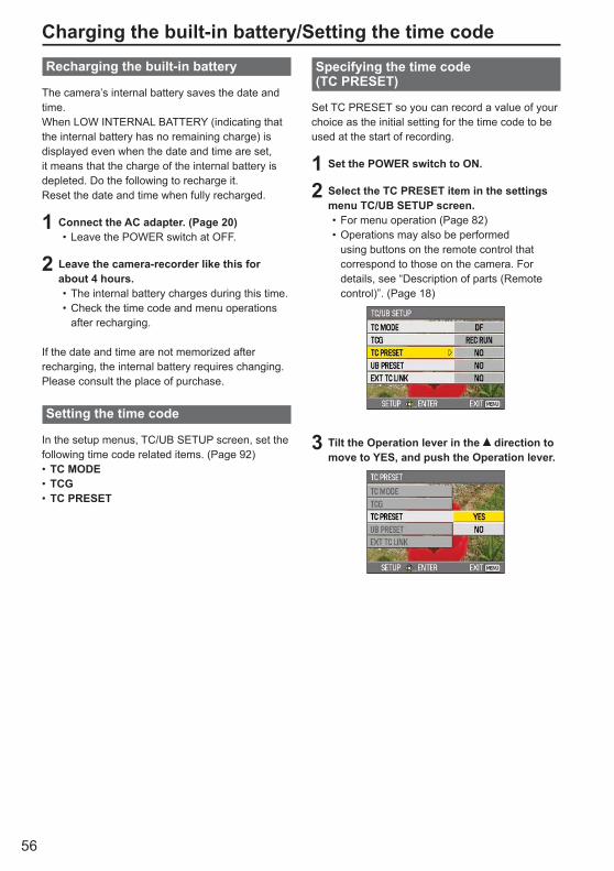
56
Recharging the built-in battery
The camera’s internal battery saves the date and time. When LOW INTERNAL BATTERY (indicating that the internal battery has no remaining charge) is displayed even when the date and time are set, it means that the charge of the internal battery is depleted. Do the following to recharge it.Reset the date and time when fully recharged.
1 Connect the AC adapter. (Page 20)Leave the POWER switch at OFF.
2 Leave the camera-recorder like this for about 4 hours.
The internal battery charges during this time.Check the time code and menu operations after recharging.
If the date and time are not memorized after recharging, the internal battery requires changing. Please consult the place of purchase.
Setting the time code
In the setup menus, TC/UB SETUP screen, set the following time code related items. (Page 92)
TC MODETCGTC PRESET
•
••
•••
Charging the built-in battery/Setting the time codeSpecifying the time code (TC PRESET)
Set TC PRESET so you can record a value of your choice as the initial setting for the time code to be used at the start of recording.
1 Set the POWER switch to ON.
2 Select the TC PRESET item in the settings menu TC/UB SETUP screen.
For menu operation (Page 82)Operations may also be performed using buttons on the remote control that correspond to those on the camera. For details, see “Description of parts (Remote control)”. (Page 18)
3 Tilt the Operation lever in the direction to move to YES, and push the Operation lever.
••

57
Shoo
ting
With this unit, the time code value is adjusted in accordance with the format and frame rate. For this reason, bear in mind that making a change in the format or frame rate may result in discontinuity from the last time code value of the previous recording.
Recording format Time codeadjustment
1080/24P720/24P
Adjustable in4-frame increments
4 When the screen below appears, set the time code value.Tilt the Operation lever in the directions and select time code value.
Tilt in the direction to move to the next digit, and tilt in the directions again to select value.
You can reset the time code to zero by pressing RESET/TC SET button.
BARS
LCD
ZEBRA OIS
EVF DTL WFM
CH1 SELECT CH2 SELECT INPUT 1 INPUT 2
SHUTTER
COUNTER RESET/TC SETAUDIO
SPEED SELECT
INT(L)INPUT1INPUT2
INT(R)INPUT2
ON
MIC POWER +48V
OFFON
OFF
Camera
5 Push the Operation lever when you have finished setting the time code.
6 Tilt the Operation lever in the direction to move to YES, and push the Operation lever.
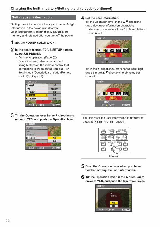
58
Setting user information
Setting user information allows you to store 8-digitinformation in the hexadecimal format.User information is automatically saved in the memory and retained after you turn off the power.
1 Set the POWER switch to ON.
2 In the setup menus, TC/UB SETUP screen, select UB PRESET.
For menu operation (Page 82)Operations may also be performed using buttons on the remote control that correspond to those on the camera. For details, see “Description of parts (Remote control)”. (Page 18)
3 Tilt the Operation lever in the direction to move to YES, and push the Operation lever.
••
4 Set the user information. Tilt the Operation lever in the directions and select user information characters.
You can use numbers from 0 to 9 and letters from A to F.
Tilt in the direction to move to the next digit, and tilt in the directions again to select character.
You can reset the user information to nothing by pressing RESET/TC SET button.
BARS
LCD
ZEBRA OIS
EVF DTL WFM
CH1 SELECT CH2 SELECT INPUT 1 INPUT 2
SHUTTER
COUNTER RESET/TC SETAUDIO
SPEED SELECT
INT(L)INPUT1INPUT2
INT(R)INPUT2
ON
MIC POWER +48V
OFFON
OFF
Camera
5 Push the Operation lever when you have finished setting the user information.
6 Tilt the Operation lever in the direction to move to YES, and push the Operation lever.
•
Charging the built-in battery/Setting the time code (continued)
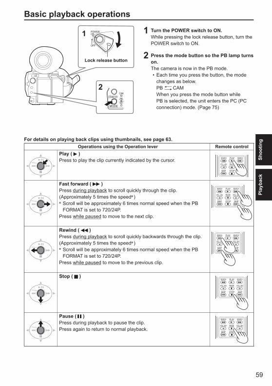
59
Shoo
ting
Play
back
1 Turn the POWER switch to ON.While pressing the lock release button, turn the POWER switch to ON.
2 Press the mode button so the PB lamp turns on.The camera is now in the PB mode.
Each time you press the button, the mode changes as below.
PB CAM When you press the mode button while
PB is selected, the unit enters the PC (PC connection) mode. (Page 75)
•
Basic playback operations
For details on playing back clips using thumbnails, see page 63.Operations using the Operation lever Remote control
Play ( )Press to play the clip currently indicated by the cursor. PLAY
STOPSKIP SKIP
PAUSE
SEARCH
STILL ADV STILL ADV
SEARCH
Fast forward ( )Press during playback to scroll quickly through the clip.(Approximately 5 times the speed∗)∗ Scroll will be approximately 6 times normal speed when the PB
FORMAT is set to 720/24P.Press while paused to move to the next clip.
PLAY
STOPSKIP SKIP
PAUSE
SEARCH
STILL ADV STILL ADV
SEARCH
Rewind ( )Press during playback to scroll quickly backwards through the clip.(Approximately 5 times the speed∗)∗ Scroll will be approximately 6 times normal speed when the PB
FORMAT is set to 720/24P.Press while paused to move to the previous clip.
PLAY
STOPSKIP SKIP
PAUSE
SEARCH
STILL ADV STILL ADV
SEARCH
Stop ( )PLAY
STOPSKIP SKIP
PAUSE
SEARCH
STILL ADV STILL ADV
SEARCH
Pause ( )Press during playback to pause the clip.Press again to return to normal playback.
PLAY
STOPSKIP SKIP
PAUSE
SEARCH
STILL ADV STILL ADV
SEARCH
POWERON
OFF
1
Lock release button
PB
2

60
Thumbnail screenVideo data created in one shooting session is called a clip. When the PB mode has been established, the clips will be displayed on the LCD monitor and the viewfinder as thumbnails. (When there is a large number of clips, it will take some time for them to be displayed on the screen.)You can perform the following operations using the thumbnail screen.
Play and delete clipsFormat SD Memory CardAdd or delete indexAdd or delete shot mark
Basic thumbnail screen operationsTo select thumbnail: Tilt the Operation lever in the directions to select thumbnail
(yellow frame moves).
To play back clips: Select the thumbnail, and push the Operation lever.
(For details on playback, see page 63.)
MENU
PUSH-ENTER
AUDIO MON/ADV
EXEC
1012
1 2 3 4
6 7 8 95
M I
0004
11
••••
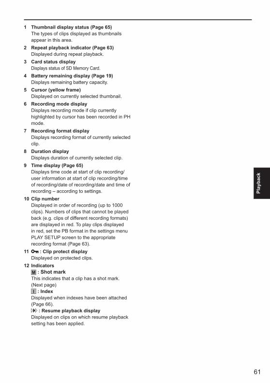
61
Play
back
1 Thumbnail display status (Page 65)The types of clips displayed as thumbnails appear in this area.
2 Repeat playback indicator (Page 63)Displayed during repeat playback.
3 Card status displayDisplays status of SD Memory Card.
4 Battery remaining display (Page 19)Displays remaining battery capacity.
5 Cursor (yellow frame)Displayed on currently selected thumbnail.
6 Recording mode displayDisplays recording mode if clip currently highlighted by cursor has been recorded in PH mode.
7 Recording format displayDisplays recording format of currently selected clip.
8 Duration displayDisplays duration of currently selected clip.
9 Time display (Page 65)Displays time code at start of clip recording/user information at start of clip recording/time of recording/date of recording/date and time of recording – according to settings.
10 Clip numberDisplayed in order of recording (up to 1000 clips). Numbers of clips that cannot be played back (e.g. clips of different recording formats) are displayed in red. To play clips displayed in red, set the PB format in the settings menu PLAY SETUP screen to the appropriate recording format (Page 63).
11 : Clip protect displayDisplayed on protected clips.
12 IndicatorsM : Shot markThis indicates that a clip has a shot mark. (Next page)I : Index
Displayed when indexes have been attached (Page 66).
: Resume playback displayDisplayed on clips on which resume playback setting has been applied.

62
Adding shot marks to clips
Adding shot marks ( M ) will make it easier to findthe clips you are looking for.
1 Tilt the Operation lever in the directions to move the yellow frame to the clip for which a shot mark is to be added.
2 Press the USER button to which the shot mark function has been allocated. (Page 88)
To release a shot mark, repeat the above steps.It is not possible to add shot marks to clips recorded using a consumer camcorder model.
•
Thumbnail screen (continued)
Direct shooting functions
If you press the START/STOP button in PB mode, the CAM mode will be automatically activated, and shooting will start.
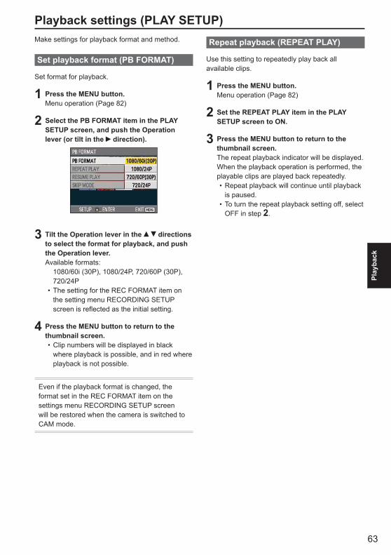
63
Play
back
Playback settings (PLAY SETUP)Make settings for playback format and method.
Set playback format (PB FORMAT)
Set format for playback.
1 Press the MENU button.Menu operation (Page 82)
2 Select the PB FORMAT item in the PLAY SETUP screen, and push the Operation lever (or tilt in the direction).
3 Tilt the Operation lever in the directions to select the format for playback, and push the Operation lever.Available formats: 1080/60i (30P), 1080/24P, 720/60P (30P),
720/24PThe setting for the REC FORMAT item on the setting menu RECORDING SETUP screen is reflected as the initial setting.
4 Press the MENU button to return to the thumbnail screen.
Clip numbers will be displayed in black where playback is possible, and in red where playback is not possible.
Even if the playback format is changed, the format set in the REC FORMAT item on the settings menu RECORDING SETUP screen will be restored when the camera is switched to CAM mode.
•
•
Repeat playback (REPEAT PLAY)
Use this setting to repeatedly play back all available clips.
1 Press the MENU button.Menu operation (Page 82)
2 Set the REPEAT PLAY item in the PLAY SETUP screen to ON.
3 Press the MENU button to return to the thumbnail screen.The repeat playback indicator will be displayed.When the playback operation is performed, the playable clips are played back repeatedly.
Repeat playback will continue until playback is paused.To turn the repeat playback setting off, select OFF in step 2.
•
•
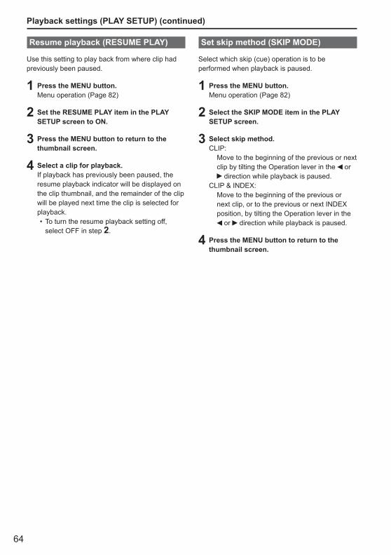
64
Playback settings (PLAY SETUP) (continued)
Resume playback (RESUME PLAY)
Use this setting to play back from where clip had previously been paused.
1 Press the MENU button.Menu operation (Page 82)
2 Set the RESUME PLAY item in the PLAY SETUP screen to ON.
3 Press the MENU button to return to the thumbnail screen.
4 Select a clip for playback.If playback has previously been paused, the resume playback indicator will be displayed on the clip thumbnail, and the remainder of the clip will be played next time the clip is selected for playback.
To turn the resume playback setting off, select OFF in step 2.
•
Set skip method (SKIP MODE)
Select which skip (cue) operation is to be performed when playback is paused.
1 Press the MENU button.Menu operation (Page 82)
2 Select the SKIP MODE item in the PLAY SETUP screen.
3 Select skip method.CLIP: Move to the beginning of the previous or next
clip by tilting the Operation lever in the or direction while playback is paused.
CLIP & INDEX: Move to the beginning of the previous or
next clip, or to the previous or next INDEX position, by tilting the Operation lever in the
or direction while playback is paused.
4 Press the MENU button to return to the thumbnail screen.
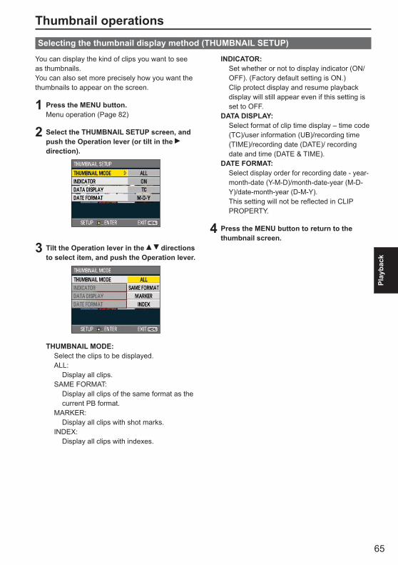
65
Play
back
Thumbnail operations
You can display the kind of clips you want to see as thumbnails.You can also set more precisely how you want the thumbnails to appear on the screen.
1 Press the MENU button.Menu operation (Page 82)
2 Select the THUMBNAIL SETUP screen, and push the Operation lever (or tilt in the direction).
3 Tilt the Operation lever in the directions to select item, and push the Operation lever.
THUMBNAIL MODE: Select the clips to be displayed. ALL: Display all clips. SAME FORMAT: Display all clips of the same format as the
current PB format. MARKER: Display all clips with shot marks. INDEX: Display all clips with indexes.
Selecting the thumbnail display method (THUMBNAIL SETUP)
INDICATOR: Set whether or not to display indicator (ON/
OFF). (Factory default setting is ON.)Clip protect display and resume playback display will still appear even if this setting is set to OFF.
DATA DISPLAY: Select format of clip time display – time code
(TC)/user information (UB)/recording time (TIME)/recording date (DATE)/ recording date and time (DATE & TIME).
DATE FORMAT: Select display order for recording date - year-
month-date (Y-M-D)/month-date-year (M-D-Y)/date-month-year (D-M-Y).
This setting will not be reflected in CLIP PROPERTY.
4 Press the MENU button to return to the thumbnail screen.

66
Thumbnail operations (continued)
Clips may be deleted or protected.
1 Press the MENU button.Menu operation (Page 82)
2 Select the OPERATION screen, and push the Operation lever (or tilt in the direction).
3 Tilt the Operation lever in the directions to select item, and push the Operation lever.
DELETE: ALL CLIPS: Delete all clips.
Select whether or not to delete (YES/NO), and push the Operation lever.
SELECT: Delete selected clips.
Select clips with the Operation lever. Selected clips will be outlined in orange. (Repeat this operation to select multiple clips.)
Press the EXEC button to confirm, tilt the Operation lever in the directions to select whether or not to delete (YES/NO), and push the Operation lever.
NO: Return to the previous screen.
Deleting and protecting clips (OPERATION)
Protected clips cannot be deleted.If selecting ALL CLIPS to delete all clips from the memory, this operation may take some time to complete, depending on the volume of clips to be deleted.Deletion cannot be performed via the remote control.
••
•
INDEX: YES: Attach indexes to selected clips. 1) Select clip to play, and push the
Operation lever at the point for an index to be added.
2) Select YES on the confirmation screen to attach index.
• The point in the clip at which the index will actually be attached will be accurate to within an error of 0.5 seconds.
• To delete index, select INDEX→YES in step 3 before performing the following.
1) Select clip to play, tilt the Operation lever in the direction, and pause the clip.
2) Tilt the Operation lever in the directions to move the pointer
between the points where indexes are attached. Move the pointer to the index to be deleted, and push the Operation lever.
3) Select YES on the confirmation screen.
NO: Return to the previous screen.
It is not possible to add indexes to clips recorded using a consumer camcorder model.It is not possible to adjust the volume during index playback.
•
•

67
Play
back
SD Memory Cards can be formatted, and clip and SD Memory Card information can be checked.
1 Press the MENU button.Menu operation (Page 82)
2 Select CARD FUNCTIONS, and push the Operation lever (or tilt in the direction).
Format card and check clip and card information (CARD FUNCTIONS)
3 Tilt the Operation lever in the directions to select item, and push the Operation lever.
CARD FORMAT:Insert card to be formatted into the camera.SD Memory Card will be formatted.
Proceeding will erase all data from card. Select whether or not to format (YES/NO),
and push the Operation lever.CARD STATUS: Display SD Memory Card information.
(Next page)CLIP PROPERTY: Display information of selected clip.
(Next page)Tilt the Operation lever in the directions to display information from previous or subsequent clips.
4 Press the MENU button to return to the thumbnail screen.
••
•
CLIP PROTECT: YES: Protect selected clips. ( mark will be displayed.) • Cancel protection when the protected
clip is selected. ( mark will disappear.) Executing a format of the memory card
(see below) will delete all clips even if they are protected.
NO: Return to the previous screen.
4 Press the MENU button to return to the thumbnail screen.
(Continued on the next page)
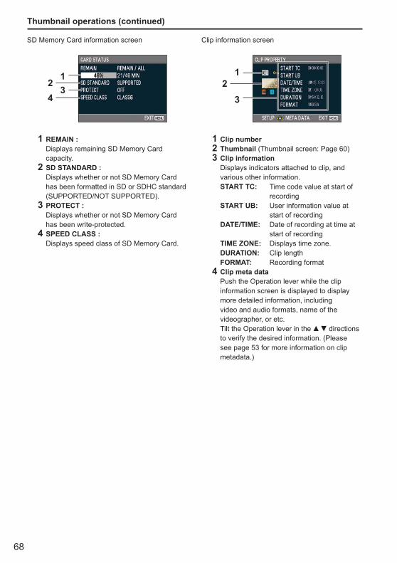
68
Thumbnail operations (continued)
SD Memory Card information screen
12
34
1 REMAIN : Displays remaining SD Memory Card
capacity.2 SD STANDARD : Displays whether or not SD Memory Card
has been formatted in SD or SDHC standard (SUPPORTED/NOT SUPPORTED).
3 PROTECT : Displays whether or not SD Memory Card
has been write-protected.4 SPEED CLASS : Displays speed class of SD Memory Card.
Clip information screen
12
3
1 Clip number2 Thumbnail (Thumbnail screen: Page 60)3 Clip information Displays indicators attached to clip, and
various other information. START TC: Time code value at start of
recording START UB: User information value at
start of recording DATE/TIME: Date of recording at time at
start of recording TIME ZONE: Displays time zone. DURATION: Clip length FORMAT: Recording format4 Clip meta data Push the Operation lever while the clip
information screen is displayed to display more detailed information, including video and audio formats, name of the videographer, or etc.Tilt the Operation lever in the directions to verify the desired information. (Please see page 53 for more information on clip metadata.)
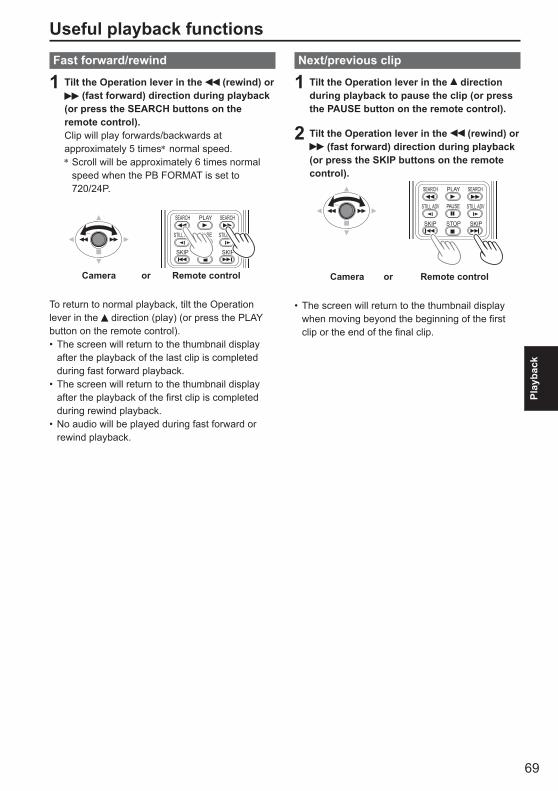
69
Play
back
Useful playback functionsFast forward/rewind
1 Tilt the Operation lever in the (rewind) or (fast forward) direction during playback
(or press the SEARCH buttons on the remote control).Clip will play forwards/backwards at approximately 5 times∗ normal speed.∗ Scroll will be approximately 6 times normal
speed when the PB FORMAT is set to 720/24P.
PLAY
STOPSKIP SKIP
PAUSE
SEARCH
STILL ADV STILL ADV
SEARCH
Camera or Remote control
To return to normal playback, tilt the Operation lever in the direction (play) (or press the PLAY button on the remote control).
The screen will return to the thumbnail display after the playback of the last clip is completed during fast forward playback.The screen will return to the thumbnail display after the playback of the first clip is completed during rewind playback.No audio will be played during fast forward or rewind playback.
•
•
•
Next/previous clip
1 Tilt the Operation lever in the direction during playback to pause the clip (or press the PAUSE button on the remote control).
2 Tilt the Operation lever in the (rewind) or (fast forward) direction during playback
(or press the SKIP buttons on the remote control).
Camera or Remote control
PLAY
STOPSKIP SKIP
PAUSE
SEARCH
STILL ADV STILL ADV
SEARCH
The screen will return to the thumbnail display when moving beyond the beginning of the first clip or the end of the final clip.
•
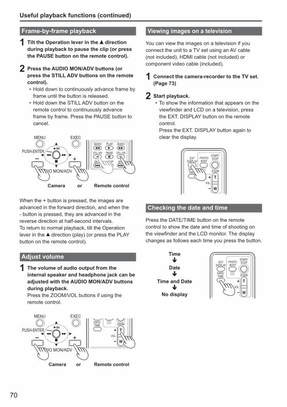
70
Useful playback functions (continued)
Frame-by-frame playback
1 Tilt the Operation lever in the direction during playback to pause the clip (or press the PAUSE button on the remote control).
2 Press the AUDIO MON/ADV buttons (or press the STILL ADV buttons on the remote control).
Hold down to continuously advance frame by frame until the button is released.Hold down the STILL ADV button on the remote control to continuously advance frame by frame. Press the PAUSE button to cancel.
Camera or Remote control
PLAY
STOPSKIP SKIP
PAUSE
SEARCH
STILL ADV STILL ADV
SEARCH
MENU
PUSH-ENTER
AUDIO MON/ADV
EXEC
When the + button is pressed, the images are advanced in the forward direction, and when the - button is pressed, they are advanced in the reverse direction at half-second intervals.To return to normal playback, tilt the Operation lever in the direction (play) (or press the PLAY button on the remote control).
Adjust volume
1 The volume of audio output from the internal speaker and headphone jack can be adjusted with the AUDIO MON/ADV buttons during playback.Press the ZOOM/VOL buttons if using the remote control.
Camera or Remote control
ZOOMDATE/TIME
VOL
MENU
PUSH-ENTER
AUDIO MON/ADV
EXEC
•
•
Viewing images on a television
You can view the images on a television if youconnect the unit to a TV set using an AV cable(not included), HDMI cable (not included) orcomponent video cable (included).
1 Connect the camera-recorder to the TV set. (Page 73)
2 Start playback.To show the information that appears on the viewfinder and LCD on a television, press the EXT. DISPLAY button on the remote control. Press the EXT. DISPLAY button again to clear the display.
ZOOM
START/STOPPHOTO
SHOTEXT
DISPLAY
DATE/TIME
VOL
Checking the date and time
Press the DATE/TIME button on the remote control to show the date and time of shooting on the viewfinder and the LCD monitor. The display changes as follows each time you press the button.
Time
Date
Time and Date
No display
ZOOM
START/STOPPHOTO
SHOTEXT
DISPLAY
DATE/TIME
VOL
•
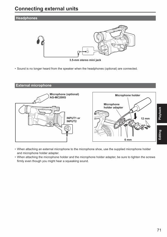
71
Play
back
Editi
ng
Connecting external unitsHeadphones
3.5-mm stereo mini jack
Sound is no longer heard from the speaker when the headphones (optional) are connected.
External microphone
Microphone (optional)AG-MC200G
INPUT1 orINPUT2
Microphone holder
Microphone holder adapter
6 mm
12 mm
When attaching an external microphone to the microphone shoe, use the supplied microphone holder and microphone holder adapter.When attaching the microphone holder and the microphone holder adapter, be sure to tighten the screws firmly even though you might hear a squeaking sound.
•
•
•

72
Connecting external units (continued)
Computer (non-linear editing/file transfer)
USB 2.0
Computer USB connection cable (optional)
Mini-B
Ferrite core (included)
For details on the computer’s conditions and other factors, see page 75.When connecting the camera with a PC using a USB connection cable, attach the two ferrite cores (included) to the USB connection cable, one at a position about 5 cm from the PC terminal and the other at a position about 5 cm from the camera terminal. After attaching the cable as shown in the diagram on the right, close the terminal so that it clicks and locks into place.
•
Always take sufficient care when handling the ferrite core, as it can be easily damaged when dropped or subjected to other impact.
•
Video deck (Dubbing)
Video and audio output will be limited to that from the camera.
Video cable (optional)
Audio cable (optional)White: CH1 (left channel) soundRed: CH2 (right channel) sound
Connect these cables to the terminals on the video deck.
VCR
When outputting video and audio signals from the camera to an external device, connect to the input terminals of the external device.
•
■
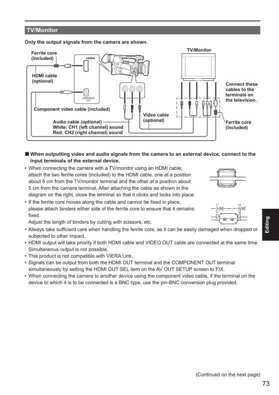
73
Editi
ng
TV/Monitor
Only the output signals from the camera are shown.
COMPONENTOUT
HDMI cable(optional)
Component video cable (included)Video cable(optional)Audio cable (optional)
White: CH1 (left channel) soundRed: CH2 (right channel) sound
Connect these cables to the terminals on the television.
TV/Monitor
Ferrite core (included)
Ferrite core (included)
When outputting video and audio signals from the camera to an external device, connect to the input terminals of the external device.
When connecting the camera with a TV/monitor using an HDMI cable, attach the two ferrite cores (included) to the HDMI cable, one at a position about 5 cm from the TV/monitor terminal and the other at a position about 5 cm from the camera terminal. After attaching the cable as shown in the diagram on the right, close the terminal so that it clicks and locks into place.
•
If the ferrite core moves along the cable and cannot be fixed in place, please attach binders either side of the ferrite core to ensure that it remains fixed.
Adjust the length of binders by cutting with scissors, etc.
•
Always take sufficient care when handling the ferrite core, as it can be easily damaged when dropped or subjected to other impact.HDMI output will take priority if both HDMI cable and VIDEO OUT cable are connected at the same time. Simultaneous output is not possible.This product is not compatible with VIERA Link.Signals can be output from both the HDMI OUT terminal and the COMPONENT OUT terminal simultaneously by setting the HDMI OUT SEL item on the AV OUT SETUP screen to FIX.When connecting the camera to another device using the component video cable, if the terminal on the device to which it is to be connected is a BNC type, use the pin-BNC conversion plug provided.
•
•
••
•
■
(Continued on the next page)
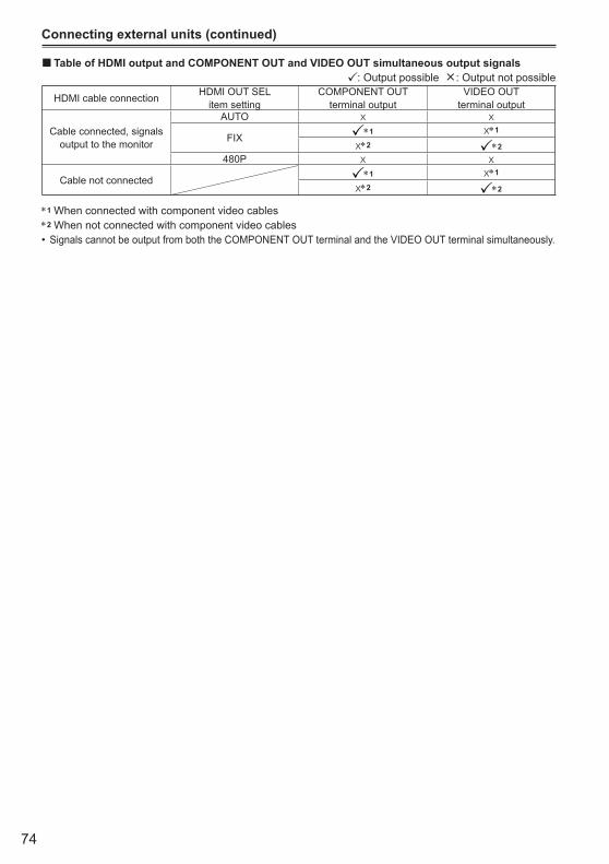
74
Connecting external units (continued)
Table of HDMI output and COMPONENT OUT and VIDEO OUT simultaneous output signals: Output possible ×: Output not possible
HDMI cable connection HDMI OUT SEL item setting
COMPONENT OUT terminal output
VIDEO OUT terminal output
Cable connected, signals output to the monitor
AUTO x x
FIX∗1 x∗1
x∗2 ∗2
480P x x
Cable not connected∗1 x∗1
x∗2 ∗2
∗1 When connected with component video cables∗2 When not connected with component video cables
Signals cannot be output from both the COMPONENT OUT terminal and the VIDEO OUT terminal simultaneously.
■
•

75
Editi
ng
Nonlinear editing (PC mode)Non-linear editing of video data on SD Memory Cards can be performed by connecting the camera via the USB connection cable to a computer for editing. (As for connection, refer to page 72)Use a sufficiently charged battery or the AC adapter.
The following conditions are necessary for USB connection.
PC with Windows 2000, Windows XP, or Windows Vista; Macintosh with Intel CPU (Intel Mac)USB 2.0 (High Speed, Mass Storage Class) compatibility (not compatible with USB 1.1)Only connect to one computer at a time.Camera cannot be operated if a hub or other device is connected between the camera and computer.Do not use a USB connection cable of more than 3 m in length. Using too long a cable may cause erroneous operation.
1 Insert the SD Memory Card, and move the POWER switch to ON.
2 Press the mode button to illuminate the PB lamp, and hold the button down again (for at least 2 seconds).The PC lamp will flash, and the camera will change to PC mode.
3 Connect the camera to the computer with the USB connection cable.Turn the computer’s power on before connecting.
When the USB connection cable is not connected, CHECK USB CABLE is displayed.
•
•
••
•
•
4 Perform non-linear editing on the computer.The contents of the SD Memory Card will appear as a removable disk icon within My Computer or the desktop on the computer screen. (Page 109)(Example) Windows
Removable disk (E:)
(Example) Macintosh
NO NAME
When copying files from the camera to a computer, be careful to ensure that files are not accidentally overwritten.For more details, please refer to your computer editing software’s operating instructions.When changing cards, always ensure that the access lamp is not flashing and that the card is not currently being accessed.Operations cannot be performed on the camera while in PC mode.Always perform “safe hardware removal” when disconnecting the cable.The data on the SD Memory Card cannot be accessed when the SD Memory Card slot cover is open.
5 Turn the camera’s power off.
If the camera cannot be correctly recognized by the computer, this may be able to be remedied by one of the following methods.
Turn the power of the camera and the computer off and back on again.Remove the SD Memory Card from the camera and reinsert it.Connect to a different USB terminal on the computer.
Hold down the mode button after disconnecting the USB connection cable to switch back to PB mode.
•
·
·
·
•
•
•
•
•
•
•
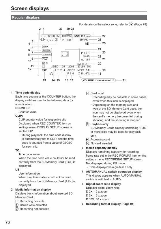
76
Screen displaysRegular displays
For details on the safety zone, refer to 32. (Page 78)
SPARK –
ALC
83 %DEC 25 2008 23 : 59 : 59
24PF 5 .6 Z 10 . 4 m
m1 / 123. 4 SPOT MF23 . 5 ft
TC 12 : 34 : 56 . 00
P 3.2 K18 dB
ND 1/64
D10X
A
CH1CH2
112 min P RECSTD BY
MARK OFF
120 min
PH 1080
R
EXPANDED
VOLUME [ + ][ ]_
5
8
10
12
1413
6
4
7
9
11
15 16 17
18
29
27
24
22
20
283012
2526
23
21
19
31
3
1 Time code displayEach time you press the COUNTER button, the display switches over to the following data (or no indication).COUNTER: Counter valueCLIP: CLIP counter value for respective clip Displayed when REC COUNTER item on
settings menu DISPLAY SETUP screen is set to CLIP.
During playback, the time code display is automatically set to CLIP, and the time code is counted from a value of 0:00:00 for each clip.
TC: Time code value. When the time code value could not be read
correctly from the SD Memory Card, [TC∗] is displayed.
UB: User information When user information could not be read
correctly from the SD Memory Card, [UB∗] is displayed.
2 Media information displayDisplays basic information about inserted SD Memory Card.
: Recording possible: Card is write-protected: Recording not possible
·
: Card is fullRecording may be possible in some cases even when this icon is displayed.Depending on the memory size and type of the SD Memory Card used, the icon may not be displayed even when the card’s memory becomes full during shooting, and the shooting is stopped.
: Playback-onlySD Memory Cards already containing 1,000 or more clips may be used for playback only.
: Accessing card: No card inserted
3 Media capacity displayDisplays remaining capacity for recording frame rate set in the REC FORMAT item on the settings menu RECORDING SETUP screen.Not displayed during PB mode.
Time displayed is a guideline only.4 AUTO/MANUAL switch operation display
This display appears when AUTO/MANUAL switch is switched to AUTO.
5 Digital zoom ratio displayDisplays digital zoom ratio.D 2X: 2 x zoomD 5X: 5 x zoomD 10X: 10 x zoom
6 Recording format display (Page 91)
·
·
•
77
Dis
play
s
(Continued on the next page)
7 Information displayFollowing information is displayed depending on the situation.
Performance of the auto white balance or the auto black balanceWarning (Page 79)The ND filter recommended under the prevailing shooting conditions is displayed.The AWB error message (LOW LIGHT / LEVEL OVER) is displayed. (Page 39)The functions allocated to the USER buttons are displayed while you hold down the DISP/ MODE CHK button.
8 EXPANDED displayDisplayed during the expanded display.
9 Microphone level automatic control displayAppears when in the setup menus, RECORDING SETUP screen, MIC ALC, you have selected “ON”.
10 Marker luminance displayWhen markers are displayed, the brightness level around the center of the screen is indicated as 0% to 99%. “99%↑” appears if the percentage is over 99.
11 Timestamp display (Page 45)12 Date and time display
Month:JAN (January), FEB (February), MAR (March), APR (April), MAY (May), JUN (June), JUL (July), AUG (August), SEP (September), OCT (October), NOV (November), DEC (December)
mmm dd yyyy hh:mm:ss
Day of the month
Year:2001 - 2039Hours
Minutes
Seconds
13 Frame rate displayDisplays recording frame rate.Not displayed when set to 1080/60i.
14 Shutter speed displayThe shutter speed is displayed here.
15 Audio level meter display (Page 49)
•
••
•
•
16 Auto iris control displaySTD: Standard auto-iris controlSPOT: Auto iris control for spotlightBACK: Auto iris control for backlight
compensation17 Iris display
Displays F value.18 Zoom position display
The zoom poison is displayed with Z00 (maximum wide-angle) - Z99 (maximum zoom).The unit can be switched to mm in the ZOOM & FOCUS item of the setting menu DISPLAY SETUP screen.
19 Focus control information displayDisplays the focus control information with 99 - 00.In the auto focus mode, AF appears. In the manual focus mode, MF appears. When the display is set to macro control, the black and white of AF or MF are displayed in reverse.95 (Focal distance: infinity):00 (Focal distance: approx. 5 cm)Depending on the zoom position, the macro range may not be enabled. Also, depending on the zoom position, the lower limit value of macro range may be different. The units can be switched between feet and m in the ZOOM & FOCUS item of the setting menu DISPLAY SETUP screen.
20 Index/shot mark recording display(INDEX/ SHOT MARK)Displayed when a USER button to which the INDEX function or SHOT MARK function has previously been allocated is pressed during recording.INVALID will be displayed if an index or shot mark cannot be attached.
21 ND filter displayND filter selected is displayed.
22 Gain displayDisplays the gain value of the image amplifier configured. (During the auto mode, AGC is displayed.)
23 AWB information displayDisplays the information of white balance.ATW: When ATW is setP3.2K/P5.6K: In the case of presetAch/Bch: In the case of A/BLOCK: When ATW is locked
78
Screen displays (continued)
24 Marker displayDuring shooting, pressing the ZEBRA button once or twice will display the marker.
25 Optical Image Stabilizer displayDisplayed when Optical Image Stabilizer is ON.
26 Scene filename display (Page 50)27 Remaining battery capacity display
When using Panasonic-manufactured batteries compatible with this product, the remaining battery capacity is displayed in minutes.Time remaining will be displayed after a brief pause.
The battery display will change→ → → →
as battery capacity decreases. will be displayed in red when less than 3 minutes are remaining, and will flash when the battery is empty. Remaining battery capacity may not be displayed correctly when using in high or low temperatures, or when the battery has not been used for a long period of time. To ensure that remaining battery capacity is displayed correctly, use the battery completely from a fully-charged state, and charge the battery again. (Remaining battery capacity may still not be displayed correctly if the battery has been used for long periods in high or low temperatures, or if the battery has been recharged a large number of times.)The remaining battery capacity display is a guideline and may change according to usage conditions.The remaining battery capacity display will momentarily disappear when switching between modes, when conducting REC CHECK operations or when changing the LCD brightness since the capacity is recalculated at these times.Not displayed when using AC adapter.
28 Operation status displayREC: RecordingPAUSE: Recording standbyCHK: Rec check
: Playback : Playback paused
INDEX [ ]: Playback paused at INDEX position
( ): Frame-by-frame playback (Frame-by-frame reverse playback)
( ): Skip (reverse skip)
•
•
•
•
•
( ): Fast forward/fast playback (Rewind/fast reverse playback)
( ): Paused in final scene (paused in initial scene)
Self-portrait recording displayNo display: Cannot record (no card, etc.)
: Recording in progress, during transition to the recording pause mode
: Recording paused (recording standby) : Warning display
29 Standby mode displayDisplayed when camera is set to standby mode
30 Recording function displayDisplayed when the PREREC MODE item on the settings menu RECORDING SETUP screen is set to ON.
P- will be displayed on the screen.31 Monitor audio level meter
When you press the AUDIO MON/ADV button, the sound volume output from the built-in speaker and headphone jack is displayed.
32 Safety zoneThe range of the zone is indicated by the SAFETY ZONE item (Page 94) on the DISPLAY SETUP screen.
4:3 This indicates the position which is cropped to 4:3.
90% This indicates the range (90%) in which signals can be displayed by an ordinary homeuse TV set.
Will not be displayed in LCD monitor or viewfinder when the FOCUS ASSIST item on the settings menu SW MODE screen is set to EXPANDED.
•
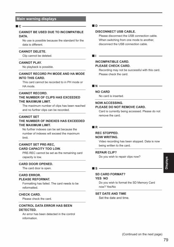
79
Dis
play
s
(Continued on the next page)
Main warning displays
C
CANNOT BE USED DUE TO INCOMPATIBLE DATA. No use is possible because the standard for the
data is different.
CANNOT DELETE. Clip cannot be deleted.
CANNOT PLAY. No playback is possible.
CANNOT RECORD PH MODE AND HA MODE INTO THIS CARD. This card cannot be recorded to in PH mode or
HA mode.
CANNOT RECORD.THE NUMBER OF CLIPS HAS EXCEEDED THE MAXIMUM LIMIT. The maximum number of clips has been reached
and no further clips can be recorded.
CANNOT SET THE NUMBER OF INDEXES HAS EXCEEDED THE MAXIMUM LIMIT. No further indexes can be set because the
number of indexes will exceed the maximum limit.
CANNOT SET PRE-REC, CARD CAPACITY TOO LOW. PRE-REC cannot be set as the remaining card
capacity is low.
CARD DOOR OPENED. The card door is open.
CARD ERROR.PLEASE REFORMAT. Formatting has failed. The card needs to be
reformatted.
CHECK CARD. Please check the card.
CONTROL DATA ERROR HAS BEEN DETECTED. An error has been detected in the control
information.
■ D
DISCONNECT USB CABLE. Please disconnect the USB connection cable.
When switching from one mode to another, disconnect the USB connection cable.
I
INCOMPATIBLE CARD.PLEASE CHECK CARD. Recording may not be successful with this card.
Please check the card.
N
NO CARD No card is inserted.
NOW ACCESSING.PLEASE DO NOT REMOVE CARD. Card is currently being accessed. Please do not
remove the card.
R
REC STOPPED.NOW WRITING. Video recording has been stopped. Data is now
being written to the card.
REPAIR CLIP? Do you wish to repair clips now?
S
SD CARD FORMAT?YES NO Do you wish to format the SD Memory Card
now? Yes/No
SET DATE AND TIME Set the date and time.
■
■
■
■
■

80
Screen displays (continued)
T
THE CLIP IS PROTECTED. PLEASE CANCEL PROTECTION. The clip is protected. Please cancel the
protection.
THE RECORDING IS STOPPED(OVER THE LIMITATION) Recording will stop. (Continuous recording for 12
hours)
THE TC MODE IS CHANGED TO "NDF" NDF is selected as the TC MODE setting.
THIS BATTERY CANNOT BE USED. This battery cannot be used.
THIS CARD CANNOT RECORD IN VIDEO MODE. The card cannot be used for video recording.
THUMBNAIL DATA ERROR IS DETECTED. An error has been detected in the thumbnail
information.
U
UNABLE TO FORMAT. The card cannot be formatted.
W
WRITE PROTECT The card is write-protected.
■
■
■
Error displays
The following messages are displayed when an error has occurred in the camera or the SD Memory Card. If the problem is not solved by switching the power off and back on again, either change the card in accordance with the instructions displayed, or consult the place of purchase.
C
CANNOT RECORD Displayed when an error has occurred during
recording.
R
REC WARNING Displayed when an error has occurred during
recording. Start the recording again. If the message appears again, please consult the place of purchase.
Please switch the power off if the message continues to appear.Please try inserting a different card if the message appears again after restarting recording.
•
•
S
SYSTEM ERRORTURN POWER OFF Displayed when an error has occurred in the
system. Switch the power off and back on again.
W
WARNING Displayed when an error has occurred with the
camera itself. Start the recording again. FOCUS NG (error with focus operation) PSD NG (error with jitter detection)
■
■
■
■

81
Dis
play
s
Setting the DISPLAY items
Display the following items on the viewfinder and LCD monitor by pressing the DISP/MODE CHKbutton or by configuring OTHER DISPLAY of the DISPLAY SETUP screen of the setup menus. (Page 94)
DisplaysMODE CHK
(Hold down DISP/MODE CHK button)
DISPLAYOTHER DISPLAY settings
ALL PARTIAL OFF
1 Time code display — — — —
2 Media information display — — —
3 Media capacity display — — —4 AUTO/MANUAL switch operation
display x
5 Digital zoom ratio display x
6 Recording format display x x7 Information display — — — — —8 EXPANDED display — — — — —9 Microphone level automatic control
display x x
11 Timestamp display ∗4 — — —
12 Date and time display ∗4 — — —
13 Frame rate display ∗1 x x
14 Shutter speed display x
15 Audio level meter display — — —
16 Auto iris control display x
17 Iris display x
18 Zoom position display — — —
19 Focus control information display — — —
21 ND filter display x x
22 Gain display ∗2 x
23 AWB information display ∗3 x24 Marker display — — — — —25 Optical Image Stabilizer display x
26 Scene filename display x x
27 Remaining battery capacity display — — —29 Standby mode display — — — — —31 Monitor audio level display — — — — —
: Displayed x: Not displayed—: Displayed depending on other settings
The item in in the MODE CHECK space appears when you press and hold the DISP/MODE CHK button.The item in in the DISPLAY space disappears when you press the DISP/MODE CHK button.∗1 Not displayed when frame rate is set to 60i.∗2 0 dB is not displayed.∗3 Only preset 3.2K and 5.6K are displayed.∗4 If the timestamp display and the date and time display are both displayed simultaneously, they will not
disappear even if the DISP/MODE CHK button is pressed.

82
Using the setup menusUse the setup menus to change the settings to suit the scenes you are shooting or what you are recording.
Operation lever
MENU buttonMENU
PUSH-ENTER
AUDIO MON/ADV
EXEC
Using the menus
The menu items indicated in the gray characters cannot be changed its settings.
•
1 When the unit is in other than playback or recording mode, press the MENU button.The following is displayed on the viewfinder and LCD monitor.CAM mode (Example)
PB mode (Example)
2 Tilt the Operation lever in the directions to move the yellow cursor to the function you wish to set.
3 Push the Operation lever (or tilt in the direction) to display the setting items.
Example:
4 Tilt the Operation lever in the directions to move the yellow cursor to the item you wish to set.
Example:
5 Push the Operation lever (or tilt in the direction) to set the item. To change values or other parameters, tilt the Operation lever in the directions.Example:
Tilt the Operation lever in the direction to return to the previous menu.
6 Repeat steps 4 - 5 to change any other items.Press the MENU button to complete settings and return to the normal screen.
•
83
Men
u
7 Repeat steps 2 - 5 to change any other settings.Press the MENU button to complete settings and return to the normal screen.
Initializing the menu settings
The menu settings contain both the user file settings and the scene file settings. You can initialize them separately.
To initialize the user file (i.e. all the settings other than the scene file settings)Select INITIALIZE in LOAD/SAVE/INIT of the USER FILE screen. The current menu settings of user file will return to the factory settings.
To initialize the scene fileFrom the 6 scene files, select the one you want to initialize with the scene dial. Then in the SCENE FILE screen, LOAD/SAVE/INIT, select INITIALIZE.The settings for only the selected scene file are returned to the factory settings.
This does not effect the other scene files.
If you wish to initialize the user file and scene files at the same time, the user file and all six scene files can be restored to their factory default settings by selecting YES for the MENU INIT item on the OTHER FUNCTIONS screen.
•

84
Setup menu structureCamera mode menu
CAM MENUSCENE FILE CARD READ/WRITE(Page 86) LOAD/SAVE/INIT
SYNCRO SCANDETAIL LEVEL
SW MODE MID GAIN V DETAIL LEVEL(Page 88) HIGH GAIN DETAIL CORING
ATW CHROMA LEVELHANDLE ZOOM CHROMA PHASEIRIS DIAL COLOR TEMP AchUSER1 COLOR TEMP BchUSER2 MASTER PEDUSER3 A.IRIS LEVELFOCUS ASSIST DRSWFM GAMMALCD KNEE
MATRIXSKIN TONE DTLNAME EDIT
AUTO SW A.IRIS(Page 90) AGC
ATWRECORDING SETUP REC FORMAT AF(Page 91) PREREC MODE
TIME STAMPTC/UB SETUP TC MODE MIC ALC(Page 92) TCG MIC GAIN1
TC PRESET MIC GAIN2UB PRESETEXT TC LINK
AV OUT SETUP HDMI OUT SEL(Page 93) CMPNT OUT SEL
DOWNCON MODEDISPLAY SETUP ZEBRA DETECT1 VIDEO SETUP(Page 94) ZEBRA DETECT2 AUDIO OUT
MARKER HP MODECARD FUNCTIONS CARD FORMAT SAFETY ZONE(Page 96) CARD STATUS REC COUNTER
VIDEO OUT OSDUSER FILE CARD READ/WRITE DATE/TIME(Page 96) LOAD/SAVE/INIT LEVEL METER
ZOOM & FOCUSMETA DATA CARD READ CARD & BATTERY(Page 96) RECORD OTHER DISPLAY
USER CLIP NAME LCD BACKLIGHTCLIP COUNT RESET LCD SETMETA DATA PROP EVF SETMETA INITIAL SET SELF SHOOT
EVF COLOROTHER FUNCTIONS IR REMOTE(Page 98) REC LAMP
BEEP SOUNDCLOCK SETTIME ZONEPOWER SAVESYSTEM INFOMENU INITOPERATION TIME
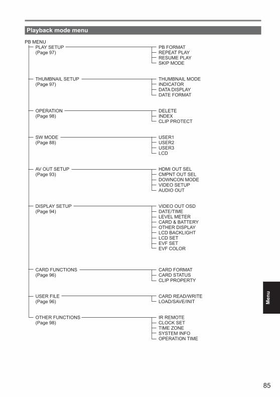
85
Men
u
Playback mode menu
PB MENUPLAY SETUP PB FORMAT(Page 97) REPEAT PLAY
RESUME PLAYSKIP MODE
THUMBNAIL SETUP THUMBNAIL MODE(Page 97) INDICATOR
DATA DISPLAYDATE FORMAT
OPERATION DELETE(Page 98) INDEX
CLIP PROTECT
SW MODE USER1(Page 88) USER2
USER3LCD
AV OUT SETUP HDMI OUT SEL(Page 93) CMPNT OUT SEL
DOWNCON MODEVIDEO SETUPAUDIO OUT
DISPLAY SETUP VIDEO OUT OSD(Page 94) DATE/TIME
LEVEL METERCARD & BATTERYOTHER DISPLAYLCD BACKLIGHTLCD SETEVF SETEVF COLOR
CARD FUNCTIONS CARD FORMAT(Page 96) CARD STATUS
CLIP PROPERTY
USER FILE CARD READ/WRITE(Page 96) LOAD/SAVE/INIT
OTHER FUNCTIONS IR REMOTE(Page 98) CLOCK SET
TIME ZONESYSTEM INFOOPERATION TIME
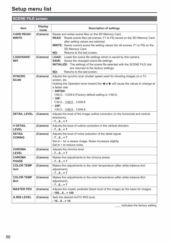
86
Setup menu listSCENE FILE screen
Item Display mode Description of settings
CARD READ/WRITE
(Camera) Reads and writes scene files on the SD Memory Card.READ: Reads scene files (all scenes, F1 to F6) saved on the SD Memory Card
after setting values are selected.WRITE: Saves current scene file setting values (for all scenes, F1 to F6) on the
SD Memory Card.NO: Returns to the last screen.
LOAD/SAVE/INIT
(Camera) LOAD: Loads the scene file settings which is saved by this camera.SAVE: Saves the changed scene file settings.INITIALIZE: The settings of the scene file selected with the SCENE FILE dial
are returned to the factory settings.NO: Returns to the last screen.
SYNCRO SCAN
(Camera) Adjusts the synchro scan shutter speed used for shooting images on a TV screen, etc.Holding the Operation lever toward the or will cause the values to change at a faster rate.
60P/60i: 1/60.0…1/249.8 (Factory default setting is 1/48.0)
30P: 1/30.0…1/48.0…1/249.8
24P: 1/24.0…1/48.0…1/249.8
•
•
•
DETAIL LEVEL (Camera) Adjusts the level of the image outline correction (in the horizontal and vertical directions).- 7…0…+ 7
V DETAIL LEVEL
(Camera) Adjusts the level of outline correction in the vertical direction.- 7…0…+ 7
DETAIL CORING
(Camera) Adjusts the level of noise reduction of the detail signal.- 7…0…+ 7Set to – for a clearer image. Noise increases slightly.Set to + to reduce noise.
CHROMA LEVEL
(Camera) Adjusts the chroma level.- 7…0…+ 7
CHROMA PHASE
(Camera) Makes fine adjustments to the chroma phase.- 7…0…+ 7
COLOR TEMP Ach
(Camera) Makes fine adjustments to the color temperature (after white balance Ach adjustment).- 7…0…+ 7
COLOR TEMP Bch
(Camera) Makes fine adjustments to the color temperature (after white balance Bch adjustment).- 7…0…+ 7
MASTER PED (Camera) Adjusts the master pedestal (black level of the image) as the basis for images.- 100…0…+ 100
A.IRIS LEVEL (Camera) Sets the desired AUTO IRIS level.- 10…0…+ 10
indicates the factory setting.
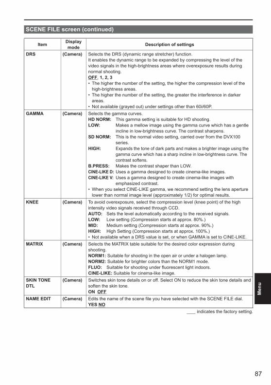
87
Men
u
SCENE FILE screen (continued)
Item Display mode Description of settings
DRS (Camera) Selects the DRS (dynamic range stretcher) function.It enables the dynamic range to be expanded by compressing the level of the video signals in the high-brightness areas where overexposure results during normal shooting.OFF, 1, 2, 3
The higher the number of the setting, the higher the compression level of the high-brightness areas.The higher the number of the setting, the greater the interference in darker areas.Not available (grayed out) under settings other than 60i/60P.
•
•
•GAMMA (Camera) Selects the gamma curves.
HD NORM: This gamma setting is suitable for HD shooting.LOW: Makes a mellow image using the gamma curve which has a gentle
incline in low-brightness curve. The contrast sharpens.SD NORM: This is the normal video setting, carried over from the DVX100
series.HIGH: Expands the tone of dark parts and makes a brighter image using the
gamma curve which has a sharp incline in low-brightness curve. The contrast softens.
B.PRESS: Makes the contrast shaper than LOW.CINE-LIKE D: Uses a gamma designed to create cinema-like images.CINE-LIKE V: Uses a gamma designed to create cinema-like images with
emphasized contrast.When you select CINE-LIKE gamma, we recommend setting the lens aperture lower than normal image level (approximately 1/2) for optimal results.
•
KNEE (Camera) To avoid overexposure, select the compression level (knee point) of the high intensity video signals received through CCD.AUTO: Sets the level automatically according to the received signals.LOW: Low setting (Compression starts at approx. 80%.)MID: Medium setting (Compression starts at approx. 90%.)HIGH: High Setting (Compression starts at approx. 100%.)
Not available when a DRS value is set, or when GAMMA is set to CINE-LIKE. •MATRIX (Camera) Selects the MATRIX table suitable for the desired color expression during
shooting.NORM1: Suitable for shooting in the open air or under a halogen lamp.NORM2: Suitable for brighter colors than the NORM1 mode.FLUO: Suitable for shooting under fluorescent light indoors.CINE-LIKE: Suitable for cinema-like image.
SKIN TONE DTL
(Camera) Switches skin tone details on or off. Select ON to reduce the skin tone details and soften the skin tone.ON OFF
NAME EDIT (Camera) Edits the name of the scene file you have selected with the SCENE FILE dial.YES NO
indicates the factory setting.
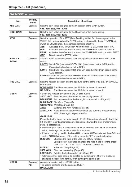
88
Setup menu list (continued)
SW MODE screen
Item Display mode Description of settings
MID GAIN (Camera) Sets the gain value assigned to the M position of the GAIN switch.0dB, 3dB, 6dB, 9dB, 12dB
HIGH GAIN (Camera) Sets the gain value assigned to the H position of the GAIN switch.0dB, 3dB, 6dB, 9dB, 12dB
ATW (Camera) Sets the operation of the ATW (Auto Tracking White) function assigned to the WHITE BAL switch. When the ATW function is allocated to the AUTO/MANUAL switch or USER button, the operation remains effective.Ach: Activates the ATW function when the WHITE BAL switch is set to A.Bch: Activates the ATW function when the WHITE BAL switch is set to B.PRST: Activates the ATW function when the WHITE BAL switch is set to PRST.OFF: Deactivates the ATW function.
HANDLE ZOOM
(Camera) Sets the zoom speed assigned to each setting position of the HANDLE ZOOM switch.L/OFF/H: Sets LOW (low speed)/OFF/HIGH (high speed) to the 1/2/3 position.
(Zoom is disabled when set to OFF.)L/M/H: Sets LOW (low speed)/MID (medium speed)/HIGH (high speed) to the
1/2/3 position.L/OFF/M: Sets LOW (low speed)/OFF/MID (medium speed) to the 1/2/3 position.
(Zoom is disabled when set to OFF.)IRIS DIAL (Camera) Sets the rotation direction and the aperture control of the IRIS dial. (In MANUAL
IRIS mode)DOWN OPEN: The iris opens when the IRIS dial is turned downward.UP OPEN: The iris opens when the IRIS dial is turned upward.
USER1 (Camera)(PB)
Selects the function assigned to the USER1 button.SPOTLIGHT: Switches auto iris control for the spotlight on or off.BACKLIGHT: Auto iris control for the backlight compensation. (Page 43)BLACKFADE: Blackfade (Page 43)WHITEFADE: Whitefade (Page 43)ATW: Switches the ATW function on or off.ATW LOCK: Fixes the white balance value when the button is pressed during
ATW. Press again to perform ATW.GAIN:18dB:Press the button to set the gain value to 18 dB. This setting takes effect with the 60i and 60P recording formats only. It is not valid when the slow shutter mode (1/15) is established.
When the gain value is switched to 18 dB or switched from 18 dB to another value, the image can be disordered for a moment.If the unit is being used in the MANUAL mode or AUTO mode, set the AGC item on the AUTO SW screen of the setting menu to OFF to use this function.
D.ZOOM: Changes the ratio of the DIGITAL ZOOM function.Each press of the button changes the ratio in the following order: OFF (x1) → x2 → x5 → x10 → OFF (x1). (Page 34)
INDEX: Index recording (Page 45)SHOT MARK: Shot mark recording (Page 45)LAST CLIP: Deletes the last recorded clip. (Page 45)
After recording, clips cannot be deleted by switching to PB or PC mode, by changing the recording format, or by turning the camera off.
•
•
•
USER2 (Camera)(PB)
Assigns a function to the USER2 button.The setting contents are the same as USER1.BACKLIGHT
indicates the factory setting.

89
Men
u
SW MODE screen (continued)
Item Display mode Description of settings
USER3 (Camera)(PB)
Assigns a function to the USER3 button.The setting contents are the same as USER1.INDEX
FOCUS ASSIST
(Camera) Assigns a function to the FOCUS ASSIST button.EXPANDED: The central part of the screen will be enlarged by a factor of about
4 in the vertical direction and by a factor of about 6 in the horizontal direction.“EXPANDED” is displayed on the screen during the expanded display.
GRAPH: Displays a frequency distribution graph at the top right in the viewfinder and LCD monitor.
BOTH: Magnifies the center portion of the image and displays a frequency distribution graph.
(The frequency distribution graph is displayed on either the viewfinder or the LCD monitor.)
WFM (Camera) Switches the waveform display that appears when the WFM button is pressed.WAVE: Displays as a waveform. Each time the button is pressed the
setting changes in this order: OFF → WAVE (waveform) → OFF. VECTOR: Displays as a vector. Each time the button is pressed the setting
changes in this order: OFF → VECTOR → OFF. WAVE/VECTOR: Each time the button is pressed the setting changes in this order:
OFF → WAVE (waveform) → VECTOR → OFF. LCD (Camera)
(PB)Assigns a function to the LCD button.LCD REV: Flips the LCD image vertically and horizontally.LCD BL: Switches the brightness of the LCD backlight.
The backlight brightness setting registered in LCD BL will remain stored even if the function allocated to the LCD button is changed.
•
indicates the factory setting.
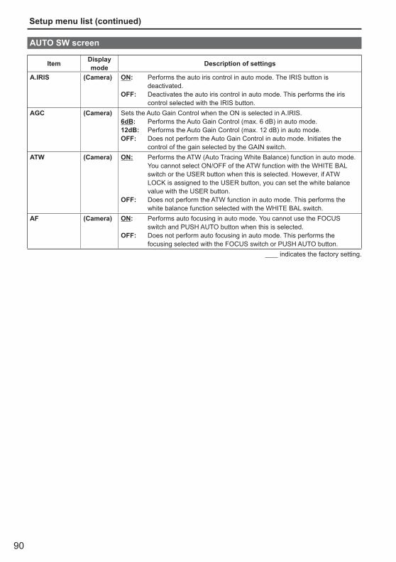
90
Setup menu list (continued)
AUTO SW screen
Item Display mode Description of settings
A.IRIS (Camera) ON: Performs the auto iris control in auto mode. The IRIS button is deactivated.
OFF: Deactivates the auto iris control in auto mode. This performs the iris control selected with the IRIS button.
AGC (Camera) Sets the Auto Gain Control when the ON is selected in A.IRIS.6dB: Performs the Auto Gain Control (max. 6 dB) in auto mode.12dB: Performs the Auto Gain Control (max. 12 dB) in auto mode.OFF: Does not perform the Auto Gain Control in auto mode. Initiates the
control of the gain selected by the GAIN switch.ATW (Camera) ON: Performs the ATW (Auto Tracing White Balance) function in auto mode.
You cannot select ON/OFF of the ATW function with the WHITE BAL switch or the USER button when this is selected. However, if ATW LOCK is assigned to the USER button, you can set the white balance value with the USER button.
OFF: Does not perform the ATW function in auto mode. This performs the white balance function selected with the WHITE BAL switch.
AF (Camera) ON: Performs auto focusing in auto mode. You cannot use the FOCUS switch and PUSH AUTO button when this is selected.
OFF: Does not perform auto focusing in auto mode. This performs the focusing selected with the FOCUS switch or PUSH AUTO button.
indicates the factory setting.

91
Men
u
RECORDING SETUP screen
Item Display mode Description of settings
REC FORMAT (Camera) Selects the recording format.PH 1080/60iPH 1080/30PPH 1080/24PPH 720/60PPH 720/30PPH 720/24PHA 1080/60iHG 1080/60iHE 1080/60i
PH 1080/24P and PH 720/24P represent native recording.•PREREC MODE
(Camera) Sets PRE RECORDING to ON or OFF. (Page 42)ON OFF
TIME STAMP (Camera) Specifies whether date and time information is superimposed over recorded images.ON: Superimposes date and time information on the image.OFF: Does not superimpose date and time information on the image.
MIC ALC (Camera) Sets mic level auto control to ON or OFF. (Page 49)ON OFFSet to ON to reduce distortion at high input levels.To adjust the recording level of audio signals (not related to this setting), use the AUDIO control knobs.
MIC GAIN1 (Camera) Sets the input level of the external microphone connected to the INPUT 1 terminal. (Page 48)-50dB -60dB
MIC GAIN2 (Camera) Sets the input level of the external microphone connected to the INPUT 2 terminal. (Page 48)-50dB -60dB
indicates the factory setting.

92
Setup menu list (continued)
TC/UB SETUP screen
Item Display mode Description of settings
TC MODE (Camera) Selects the correction mode of the internal time code generator when the time code of the internal time code generator is recorded.DF: Uses the drop frame mode.NDF: Uses the non-drop frame mode.
TC MODE is automatically set to NDF when you set recording frame rate of recording format to 24P.
•
TCG (Camera) Sets the mode in which you advance the internal time code generator.FREE RUN: The time code is advanced regardless of the operation mode.
A slight time error may occur when switching to PB mode if the frame rate is set to 24P.
REC RUN: The time code is advanced only when recording.TC PRESET (Camera) Sets the initial time code.
YES NOSet the frame value to 0 or a multiple of 4 when you set recording frame rate of recording format to 24P. If any other value is set, the recorded time code will mis-match.
•
UB PRESET (Camera) Sets the user information. YES NO
EXT TC LINK (Camera) Synchronizes the initial time code value during multi-camera shooting. (Slave camera time codes are synchronized to the master internal TCG value.) (Page 55)MASTER: Sets the mode to master mode. SLAVE: Sets the mode to slave mode.
When the COUNTER - RESET/TC SET button is pressed, input time codes are synchronized to the internal TCG.
NO: Returns to the last screen.Master and slave mode settings are only in effect when this menu is open. When the menu is closed, EXT TC LINK is automatically canceled.
•
indicates the factory setting.
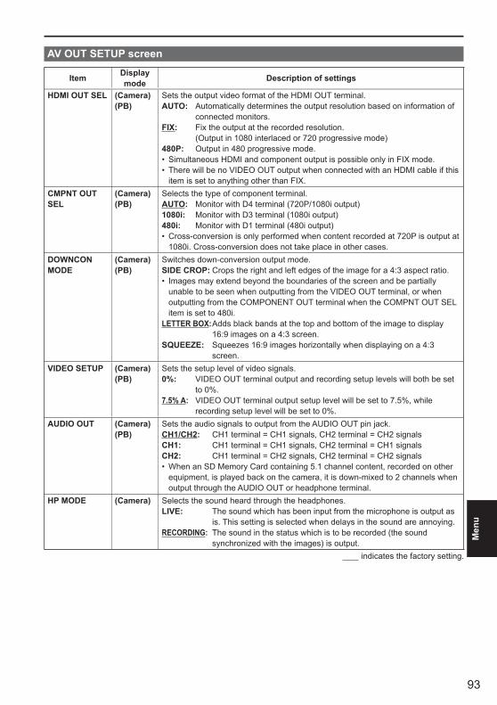
93
Men
u
AV OUT SETUP screen
Item Display mode Description of settings
HDMI OUT SEL (Camera)(PB)
Sets the output video format of the HDMI OUT terminal. AUTO: Automatically determines the output resolution based on information of
connected monitors. FIX: Fix the output at the recorded resolution.
(Output in 1080 interlaced or 720 progressive mode)480P: Output in 480 progressive mode.
Simultaneous HDMI and component output is possible only in FIX mode.There will be no VIDEO OUT output when connected with an HDMI cable if this item is set to anything other than FIX.
••
CMPNT OUT SEL
(Camera)(PB)
Selects the type of component terminal.AUTO: Monitor with D4 terminal (720P/1080i output)1080i: Monitor with D3 terminal (1080i output)480i: Monitor with D1 terminal (480i output)
Cross-conversion is only performed when content recorded at 720P is output at 1080i. Cross-conversion does not take place in other cases.
•
DOWNCON MODE
(Camera)(PB)
Switches down-conversion output mode.SIDE CROP: Crops the right and left edges of the image for a 4:3 aspect ratio.
Images may extend beyond the boundaries of the screen and be partially unable to be seen when outputting from the VIDEO OUT terminal, or when outputting from the COMPONENT OUT terminal when the COMPNT OUT SEL item is set to 480i.
LETTER BOX: Adds black bands at the top and bottom of the image to display 16:9 images on a 4:3 screen.
SQUEEZE: Squeezes 16:9 images horizontally when displaying on a 4:3 screen.
•
VIDEO SETUP (Camera)(PB)
Sets the setup level of video signals.0%: VIDEO OUT terminal output and recording setup levels will both be set
to 0%.7.5% A: VIDEO OUT terminal output setup level will be set to 7.5%, while
recording setup level will be set to 0%.AUDIO OUT (Camera)
(PB)Sets the audio signals to output from the AUDIO OUT pin jack.CH1/CH2: CH1 terminal = CH1 signals, CH2 terminal = CH2 signalsCH1: CH1 terminal = CH1 signals, CH2 terminal = CH1 signalsCH2: CH1 terminal = CH2 signals, CH2 terminal = CH2 signals
When an SD Memory Card containing 5.1 channel content, recorded on other equipment, is played back on the camera, it is down-mixed to 2 channels when output through the AUDIO OUT or headphone terminal.
•
HP MODE (Camera) Selects the sound heard through the headphones.LIVE: The sound which has been input from the microphone is output as
is. This setting is selected when delays in the sound are annoying.RECORDING: The sound in the status which is to be recorded (the sound
synchronized with the images) is output. indicates the factory setting.

94
Setup menu list (continued)
DISPLAY SETUP screen
Item Display mode Description of settings
ZEBRA DETECT1
(Camera) Selects the brightness level of the left-leaning zebra patterns on the screen.50%, 55%, 60%, 65%, 70%, 75%, 80%, 85%, 90%, 95%, 100%, 105%
ZEBRA DETECT2
(Camera) Selects the brightness level of the right-leaning zebra patterns on the screen.50%, 55%, 60%, 65%, 70%, 75%, 80%, 85%, 90%, 95%, 100%, 105%, OFF
The zebra patterns do not appear if you select OFF.•MARKER (Camera) Select ON to display the marker. (Page 42)
ON OFFTo display the marker, press the ZEBRA button.
SAFETY ZONE (Camera) Sets SAFETY ZONE. (Page 78)90%, 4:3, OFF
REC COUNTER (Camera) Selects counter operation during recording.TOTAL: The count continues to increase until the RESET/TC SET button is
pressed to reset it. CLIP: Resets the counter at start of recording and counts the time of each
recording session.In PB mode, operation is always in CLIP mode. •
VIDEO OUT OSD
(Camera)(PB)
Select ON to output the information displayed on the screen together with the signals from the VIDEO OUT jack.ON OFF
DATE/TIME (Camera)(PB)
Sets whether to display the date and time on the screen and whether to output from the VIDEO OUT jack.TIME: The time is displayed.DATE: The date is displayed.TIME & DATE: The date and time are displayed.OFF: The date and time are not displayed.
LEVEL METER (Camera)(PB)
Select ON to display the audio level meter.ON OFF
ZOOM & FOCUS
(Camera) Selects the unit of zoom and focus values.OFF, NUMBER, mm/feet, mm/m
Use the mm/feet or mm/m display only as a general guideline since it is not entirely accurate.
•
CARD & BATTERY
(Camera)(PB)
Select ON to display the remaining SD Memory Card recording capacity and remaining battery charge.ON OFF
OTHER DISPLAY
(Camera)(PB)
Select how much information to display on the viewfinder and the LCD monitor. (Page 81)PARTIAL, ALL, OFF
LCD BACKLIGHT
(Camera)(PB)
Adjusts the backlight of the LCD monitor. Select HIGH for brighter backlight.LOW, NORMAL, HIGH
LCD SET (Camera)(PB)
Adjusts the display level of the images on the LCD monitor. (Page 26)LCD COLOR LEVELLCD BRIGHTNESSLCD CONTRAST
EVF SET (Camera)(PB)
Adjusts the display level of the images on the viewfinder. (Page 26)EVF COLOR LEVELEVF BRIGHTNESSEVF CONTRAST
indicates the factory setting.

95
Men
u
Item Display mode Description of settings
SELF SHOOT (Camera) Selects the LCD mirror mode for self-portrait shooting. Selecting MIRROR displays the left and right side of the LCD monitor image inverted during self-portrait shooting. (Page 41)NORMAL, MIRROR
EVF COLOR (Camera)(PB)
Switches viewfinder images to color or black and white.ON: ColorOFF: Black and white
indicates the factory setting.
DISPLAY SETUP screen (continued)
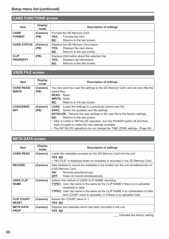
96
Setup menu list (continued)
CARD FUNCTIONS screen
Item Display mode Description of settings
CARD FORMAT
(Camera)(PB)
Formats the SD Memory Card. YES: Formats the card. NO: Returns to the last screen.
CARD STATUS (Camera)(PB)
Displays the SD Memory Card status. YES: Displays the card status. NO: Returns to the last screen.
CLIP PROPERTY
(PB) Displays information about the selected clip. YES: Displays clip information. NO: Returns to the last screen.
USER FILE screen
Item Display mode Description of settings
CARD READ/WRITE
(Camera)(PB)
You can save four user file settings to the SD Memory Card, and can also title the saved files.READ: ReadWRITE: WriteNO: Returns to the last screen.
LOAD/SAVE/INIT
(Camera)(PB)
LOAD: Loads the settings in a previously stored user file.SAVE: Saves the updated user file settings.INITIALIZE: Returns the user settings in the user file to the factory settings.NO: Returns to the last screen.
After a LOAD or INITIALIZE operation, turn the POWER switch off and then back on again to make the new settings available.The INITIALIZE operations do not change the TIME ZONE settings. (Page 99)
•
•
META DATA screen
Item Display mode Description of settings
CARD READ (Camera) Loads the metadata recorded on the SD Memory Card into the unit.YES NO
“NO FILE” is displayed when no metadata is recorded in the SD Memory Card.•RECORD (Camera) Sets whether to record the metadata to be loaded into the unit simultaneously on
a SD Memory Card.ON: Records simultaneously.OFF: Does not record simultaneously.
USER CLIP NAME
(Camera) Selects the method of USER CLIP NAME recording.TYPE1: User clip name is the same as the CLIP NAME if there is no uploaded
metadata or data.TYPE2: User clip name is the same as the CLIP NAME if no combination of data
and COUNT value is uploaded, or if there is no uploaded data.CLIP COUNT RESET
(Camera) Resets the COUNT value to 1. YES NO
META DATA PROP
(Camera) Displays the metadata which has been recorded in the unit.YES NO
indicates the factory setting.
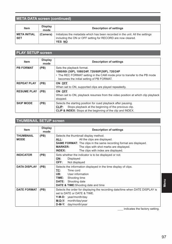
97
Men
u
Item Display mode Description of settings
META INITIAL SET
(Camera) Initializes the metadata which has been recorded in the unit. All the settings including the ON or OFF setting for RECORD are now cleared.YES NO
PLAY SETUP screen
Item Display mode Description of settings
PB FORMAT (PB) Sets the playback format.1080/60i (30P), 1080/24P, 720/60P(30P), 720/24P
The REC FORMAT setting in the CAM mode prior to transfer to the PB mode becomes the initial setting of PB FORMAT.
•
REPEAT PLAY (PB) ON OFFWhen set to ON, supported clips are played repeatedly.
RESUME PLAY (PB) ON OFFWhen set to ON, playback resumes from the video position at which clip playback stopped.
SKIP MODE (PB) Selects the starting position for cued playback after pausing. CLIP: Stops playback at the beginning of the previous clip. CLIP & INDEX: Stops at the beginning of the clip and INDEX.
THUMBNAIL SETUP screen
Item Display mode Description of settings
THUMBNAIL MODE
(PB) Selects the thumbnail display method.ALL: All the clips are displayed.SAME FORMAT: The clips in the same recording format are displayed.MARKER: The clips with shot marks are displayed.INDEX: The clips with index are displayed.
INDICATOR (PB) Sets whether the indicator is to be displayed or not.ON: DisplayedOFF: Not displayed
DATA DISPLAY (PB) Selects the information displayed in the time display of clips. TC: Time cordUB: User informationTIME: Shooting timeDATE: Shooting dateDATE & TIME:Shooting date and time
DATE FORMAT (PB) Selects the order for displaying the recording date/time when DATE DISPLAY is set to DATE or DATE & TIME.Y-M-D: year/month/dayM-D-Y: month/day/yearD-M-Y: day/month/year
indicates the factory setting.
META DATA screen (continued)
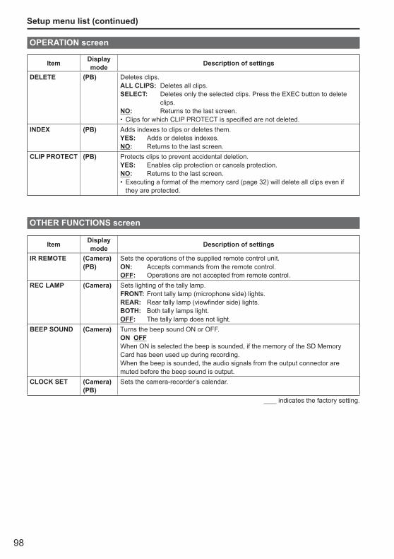
98
Setup menu list (continued)
OPERATION screen
Item Display mode Description of settings
DELETE (PB) Deletes clips. ALL CLIPS: Deletes all clips. SELECT: Deletes only the selected clips. Press the EXEC button to delete
clips. NO: Returns to the last screen.
Clips for which CLIP PROTECT is specified are not deleted. •INDEX (PB) Adds indexes to clips or deletes them.
YES: Adds or deletes indexes. NO: Returns to the last screen.
CLIP PROTECT (PB) Protects clips to prevent accidental deletion. YES: Enables clip protection or cancels protection. NO: Returns to the last screen.
Executing a format of the memory card (page 32) will delete all clips even if they are protected.
•
OTHER FUNCTIONS screen
Item Display mode Description of settings
IR REMOTE (Camera)(PB)
Sets the operations of the supplied remote control unit. ON: Accepts commands from the remote control.OFF: Operations are not accepted from remote control.
REC LAMP (Camera) Sets lighting of the tally lamp.FRONT: Front tally lamp (microphone side) lights.REAR: Rear tally lamp (viewfinder side) lights.BOTH: Both tally lamps light.OFF: The tally lamp does not light.
BEEP SOUND (Camera) Turns the beep sound ON or OFF.ON OFFWhen ON is selected the beep is sounded, if the memory of the SD Memory Card has been used up during recording.When the beep is sounded, the audio signals from the output connector are muted before the beep sound is output.
CLOCK SET (Camera)(PB)
Sets the camera-recorder’s calendar.
indicates the factory setting.
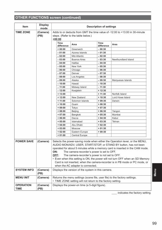
99
Men
u
OTHER FUNCTIONS screen (continued)
Item Display mode Description of settings
TIME ZONE (Camera)(PB)
Adds to or deducts from GMT the time value of -12:00 to +13:00 in 30-minute steps. (Refer to the table below.)+00:00
Time difference Area Time
difference Area
+ 00:00 Greenwich – 00:30– 01:00 Azores Islands – 01:30– 02:00 Mid-Atlantic – 02:30– 03:00 Buenos Aires – 03:30 Newfoundland Island– 04:00 Halifax – 04:30– 05:00 New York – 05:30– 06:00 Chicago – 06:30– 07:00 Denver – 07:30– 08:00 Los Angeles – 08:30– 09:00 Alaska – 09:30 Marquesas Islands– 10:00 Hawaii – 10:30– 11:00 Midway Island – 11:30– 12:00 Kwajalein + 12:30+ 13:00 + 11:30 Norfolk Island+ 12:00 New Zealand + 10:30 Lord Howe Island+ 11:00 Solomon Islands + 09:30 Darwin+ 10:00 Guam + 08:30+ 09:00 Tokyo + 07:30+ 08:00 Beijing + 06:30 Yangon+ 07:00 Bangkok + 05:30 Mumbai+ 06:00 Dacca + 04:30 Kabul+ 05:00 Islamabad + 03:30 Tehran+ 04:00 Abu Dhabi + 02:30+ 03:00 Moscow + 01:30+ 02:00 Eastern Europe + 00:30+ 01:00 Central Europe
POWER SAVE (Camera) Selects the power-saving mode when either the Operation lever, or the MENU, AUDIO MON/ADV, USER, START/STOP, or STAND BY button, has not been operated for about 5 minutes while a memory card is inserted in the CAM mode.ON: The camera-recorder’s power is set to OFF.OFF: The camera-recorder’s power is not set to OFF.
Even when this setting is ON, the power will not turn OFF when an SD Memory Card is not inserted, when the camera-recorder is in PB mode or PC mode, or when the AC adapter is connected.
•
SYSTEM INFO (Camera)(PB)
Displays the version of the system in this camera.
MENU INIT (Camera) Returns the menu settings (scene file, user file) to the factory settings.TIME ZONE setting will not return to the factory setting.•
OPERATION TIME
(Camera)(PB)
Displays the power-on time (a 5-digit figure).
indicates the factory setting.
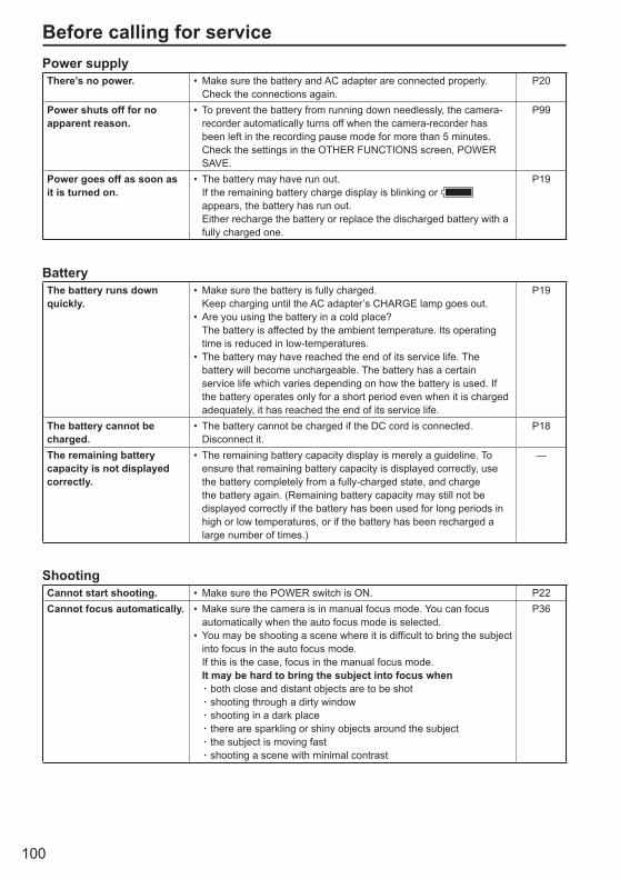
100
Before calling for servicePower supplyThere’s no power. Make sure the battery and AC adapter are connected properly.
Check the connections again.• P20
Power shuts off for no apparent reason.
To prevent the battery from running down needlessly, the camera-recorder automatically turns off when the camera-recorder has been left in the recording pause mode for more than 5 minutes.Check the settings in the OTHER FUNCTIONS screen, POWER SAVE.
• P99
Power goes off as soon as it is turned on.
The battery may have run out.If the remaining battery charge display is blinking or appears, the battery has run out. Either recharge the battery or replace the discharged battery with a fully charged one.
• P19
BatteryThe battery runs down quickly.
Make sure the battery is fully charged.Keep charging until the AC adapter’s CHARGE lamp goes out.Are you using the battery in a cold place?The battery is affected by the ambient temperature. Its operating time is reduced in low-temperatures.The battery may have reached the end of its service life. The battery will become unchargeable. The battery has a certain service life which varies depending on how the battery is used. If the battery operates only for a short period even when it is charged adequately, it has reached the end of its service life.
•
•
•
P19
The battery cannot be charged.
The battery cannot be charged if the DC cord is connected.Disconnect it.
• P18
The remaining battery capacity is not displayed correctly.
The remaining battery capacity display is merely a guideline. To ensure that remaining battery capacity is displayed correctly, use the battery completely from a fully-charged state, and charge the battery again. (Remaining battery capacity may still not be displayed correctly if the battery has been used for long periods in high or low temperatures, or if the battery has been recharged a large number of times.)
• —
ShootingCannot start shooting. Make sure the POWER switch is ON.• P22Cannot focus automatically. Make sure the camera is in manual focus mode. You can focus
automatically when the auto focus mode is selected.You may be shooting a scene where it is difficult to bring the subject into focus in the auto focus mode.If this is the case, focus in the manual focus mode.It may be hard to bring the subject into focus when
both close and distant objects are to be shotshooting through a dirty windowshooting in a dark placethere are sparkling or shiny objects around the subjectthe subject is moving fastshooting a scene with minimal contrast
•
•
······
P36
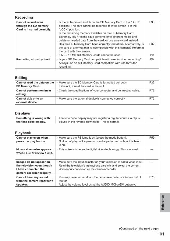
101
Ref
eren
ce
RecordingCannot record even through the SD Memory Card is inserted correctly.
Is the write-protect switch on the SD Memory Card in the “LOCK” position? The card cannot be recorded to if the switch is in the “LOCK” position.Is the remaining memory available on the SD Memory Card extremely low? Please save contents onto different media and delete unneeded data from the card, or use a new card instead.Has the SD Memory Card been correctly formatted? Alternatively, is the card of a format that is incompatible with this camera? Reformat the card with the camera.8 MB - 16 MB SD Memory Cards cannot be used.
•
•
•
•
P33
P32
P9Recording stops by itself. Is your SD Memory Card compatible with use for video recording?
Always use an SD Memory Card compatible with use for video recording.
• P9
EditingCannot read the data on the SD Memory Card.
Make sure the SD Memory Card is formatted correctly.If it is not, format the card in the unit.
• P32
Cannot perform nonlinear editing.
Check the specifications of your computer and connecting cable.• P75
Cannot dub onto anexternal device.
Make sure the external device is connected correctly.• P72
DisplaysSomething is wrong withthe time code display.
The time code display may not register a regular count if a clip is played in the reverse slow mode. This is normal.
• —
PlaybackCannot play even when Ipress the play button.
Make sure the PB lamp is on (press the mode button).No kind of playback operation can be performed unless this lamp is on.
• P59
Mosaic-like noise appears when I cue or review a clip.
This noise is inherent to digital video technology. This is normal.• —
Images do not appear on the television even though I have connected the camera-recorder properly.
Make sure the input selector on your television is set to video input.Read the television’s instructions carefully and select the correct video input connector for the camera-recorder.
• —
Cannot hear any sound from the camera-recorder’s speaker.
You may have turned down the camera-recorder’s volume control too far.Adjust the volume level using the AUDIO MON/ADV button +.
• P70
(Continued on the next page)
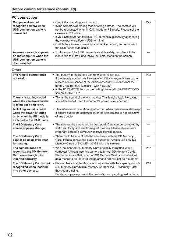
102
PC connectionComputer does not recognize camera when USB connection cable is connected.
Check the operating environment.Is the camera’s operating mode setting correct? The camera will not be recognized when in CAM mode or PB mode. Please set the camera to PC mode.If your computer has multiple USB terminals, please try connecting the camera to a different USB terminal.Switch the camera’s power off and back on again, and reconnect the USB connection cable.
••
•
•
P75
An error message appears on the computer when the USB connection cable is disconnected.
To disconnect the USB connection cable safely, double-click the icon in the task tray, and follow the instructions on the screen.
• —
OtherThe remote control doesnot work.
The battery in the remote control may have run out. If the remote control fails to work even if it is operated close to the remote control sensor of the camera-recorder, it means that the battery has run out. Replace it with new one.Is the IR REMOTE item on the setting menu OTHER FUNCTIONS screen set to OFF?
•
•
P22
There is a rattling sound when the camera-recorder is tilted back and forth.
This is the sound of the lens moving. This is not a fault. No sound should be heard when the camera’s power is switched on.
• —
A clicking sound is heard when the power is turned on or when the PB mode is switched to the CAM mode.
This initialization operation is performed when the camera starts up. It occurs due to the construction of the camera and is not indicative of any trouble.
• —
The SD Memory Card screen appears strange.
The data on the card could be corrupted. Data can be corrupted by static electricity and electromagnetic waves. Please always save important data to a computer or other storage media.
• —
The SD Memory Card cannot be used even after formatting.
There could be a fault with the camera or with the SD Memory Card. Please consult the place of purchase. Always use only SD Memory Cards of 512 MB - 32 GB with this camera.
• —
The camera does not recognize the SD Memory Card even though it is inserted correctly.
Was the inserted SD Memory Card originally formatted with a computer? Always use this camera to format SD Memory Cards. Please be aware that, when an SD Memory Card is formatted, all data recorded on the card will be erased and will not be restorable.
• P32
The SD Memory Card is not recognized when inserted into other devices.
Please check that the device is compatible with the capacity or type (SD Memory Card/SDHC Memory Card) of the SD Memory Card that you are using. For details, please consult the device’s own operating instructions.
• P10
Before calling for service (continued)
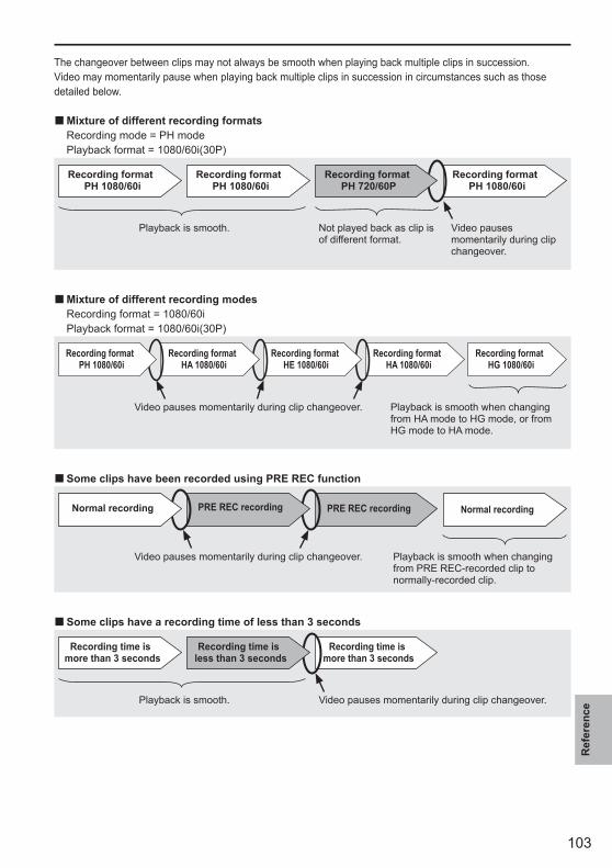
103
Ref
eren
ce
The changeover between clips may not always be smooth when playing back multiple clips in succession.Video may momentarily pause when playing back multiple clips in succession in circumstances such as those detailed below.
Mixture of different recording formats Recording mode = PH mode Playback format = 1080/60i(30P)
Recording formatPH 1080/60i
Recording formatPH 1080/60i
Recording formatPH 1080/60i
Playback is smooth. Not played back as clip is of different format.
Video pauses momentarily during clip changeover.
Recording formatPH 720/60P
Mixture of different recording modes Recording format = 1080/60i Playback format = 1080/60i(30P)
Video pauses momentarily during clip changeover. Playback is smooth when changing from HA mode to HG mode, or from HG mode to HA mode.
Recording formatHA 1080/60i
Recording formatHG 1080/60i
Recording formatHE 1080/60i
Recording formatHA 1080/60i
Recording format PH 1080/60i
Some clips have been recorded using PRE REC function
PRE REC recording Normal recording
Video pauses momentarily during clip changeover. Playback is smooth when changing from PRE REC-recorded clip to normally-recorded clip.
PRE REC recordingNormal recording
Some clips have a recording time of less than 3 seconds
Recording time is more than 3 seconds
Playback is smooth. Video pauses momentarily during clip changeover.
Recording time is more than 3 seconds
Recording time is less than 3 seconds
■
■
■
■
104
Operating precautionsDo not allow any water to get into the camera-recorder when using it in the rain or snow or at the beach.
Failure to heed this caution will cause the camera-recorder or a card to malfunction (and may result in irreparable damage).
Keep the camera-recorder away from equipment (such as TV sets and video game machines) that generate magnetic fields.
Using the camera-recorder on top of or near a TV set may cause distortion in the images and/or sound due to the electromagnetic waves that the set emits.The powerful magnetic fields generated by speakers or large motors may damage your recordings or distort the images.The electromagnetic waves emitted from a microcomputer will adversely affect the camera-recorder, causing the images and/or sound to be distorted.If the camera-recorder is so adversely affected by products that generate magnetic fields that it no longer operates properly, turn it off and remove the battery or unplug the AC adapter from the power outlet. Then install the battery again or reconnect the AC adapter. After this, turn the camera-recorder back on.
Do not use the camera-recorder near radio transmitters or high-voltage equipment.
Using the camera-recorder near a radio transmitter or high-voltage equipment may adversely affect the recorded images and/or sound.
Do not allow any sand or dust to get into the camera-recorder when using it at the beach and other similar places.
Sand and dust can damage the camera-recorder or a card. (Be especially careful when inserting or removing a card.)
AC adapter and batteryIf the CHARGE lamp continues to blink even when the battery temperature is normal, there may be something wrong with the battery or AC adapter. Contact your dealer.The battery takes longer to charge when it is warm.The AC adapter can interfere with radio reception so keep radios at least 1 meter away from it.
•
•
•
•
•
•
•
•
•
•
The AC adapter may make some noise when you are using it, but this is normal.
Take precautions not to drop the camera when moving it.
Strong impacts may damage the camera and cause it to stop working.Handle the camera with care, using the hand strap or shoulder strap to carry it.
Do not spray the camera with insect sprays or other volatile substances.
These can warp the camera or cause the finish to come off.Do not leave the camera-recorder in contact with rubber or PVC products for extended periods of time.
After use, remove the battery and disconnect the AC power supply cord.
Battery characteristicsThis camera-recorder uses a rechargeable lithiumion battery that uses its internal chemical reaction to generate electrical energy. This reaction is easily influenced by the ambient temperature and humidity, and the battery’s effective operating time is reduced as the temperature rises or falls. In very low temperatures, the battery may last only 5 minutes.Protective circuitry functions if you use the battery where it is very hot and you will have to wait before you can use it again.
Remove the battery after use.Completely remove the battery. (The battery continues to be used even if you have turned the camera off.) The battery can over discharge if you leave it in the camera and it may become impossible to recharge it.
Disposing of spent batteriesThe battery will become unchargeable. Rather than throwing the battery into the garbage, take it to a store that can assist in recycling it.
•
•
•
•
•
105
Ref
eren
ce
What to remember when throwing memory cards away or transferring them to othersFormatting memory cards or deleting data using the functions of the unit or a computer will merely change the file management information: it will not completely erase the data on the cards. When throwing these cards away or transferring them to others, either physically destroy them or use a data deletion program for computers (commercially available) to completely erase the data. Users are responsible for managing the data on their memory cards.
Liquid crystal displaysImages or letters can get burned onto the screen of the LCD or viewfinder if they are displayed for a long time, but you can fix this by leaving the camera off for several hours.The liquid crystal parts are highly precise with 99.99% of the pixels effective. This leaves less than 0.01% of pixels that may not light or may remain on all the time. These phenomena are normal and will have no effect on the images you shoot.Condensation may form if you use the camera where temperatures fluctuate. Wipe dry with a soft, dry cloth.The LCD may appear dim after immediately turning on a cold camera, but will brighten as the camera warms up.
Do not point the lens or viewfinder at the sun.Doing so may damage the parts inside.
Protective caps for the connectorsKeep the protective caps fitted over any connectors that are not being used.
•
•
•
•
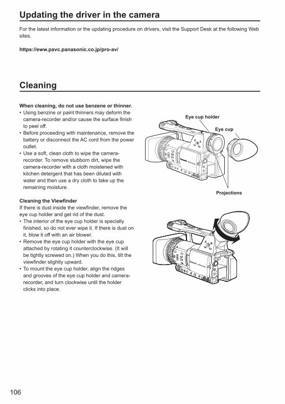
106
Updating the driver in the cameraFor the latest information or the updating procedure on drivers, visit the Support Desk at the following Web sites.
https://eww.pavc.panasonic.co.jp/pro-av/
Cleaning
When cleaning, do not use benzene or thinner.Using benzine or paint thinners may deform the camera-recorder and/or cause the surface finish to peel off.Before proceeding with maintenance, remove the battery or disconnect the AC cord from the power outlet.Use a soft, clean cloth to wipe the camera-recorder. To remove stubborn dirt, wipe the camera-recorder with a cloth moistened with kitchen detergent that has been diluted with water and then use a dry cloth to take up the remaining moisture.
Cleaning the ViewfinderIf there is dust inside the viewfinder, remove the eye cup holder and get rid of the dust.
The interior of the eye cup holder is specially finished, so do not ever wipe it. If there is dust on it, blow it off with an air blower.Remove the eye cup holder with the eye cup attached by rotating it counterclockwise. (It will be tightly screwed on.) When you do this, tilt the viewfinder slightly upward.To mount the eye cup holder, align the ridges and grooves of the eye cup holder and camera-recorder, and turn clockwise until the holder clicks into place.
•
•
•
•
•
•
Eye cup holder
Eye cup
Projections
107
Ref
eren
ce
Storage PrecautionsBefore storing the camera-recorder, remove both the SD Memory Card and battery.Store all of these items in a place with low humidity and relatively constant temperature.[Recommended temperature range: 15°C to 25°C (59 °F to 77 °F )][Recommended relative humidity: 40% to 60%]
Camera-recorderWrap the camera-recorder in a soft cloth to keep the dust off.
BatteryThe battery life is shortened in places with extreme temperatures.Storing the battery in a location with oily vapors or high dust concentrations may corrode the terminals or cause other damage, leading to malfunction.Keep metal objects (such as necklaces and hairpins) away from the terminals. Short-circuiting may occur across the terminals, causing the battery to heat up, and you may seriously burn yourself if you touch the battery in this state.
•
•
•
•
SD Memory CardsAfter ejecting an SD Memory Card from the unit, be absolutely sure to stow it in its own case.Do not leave SD Memory Cards in areas where corrosive gases, etc. are present.Do not leave the cards inside vehicles, in places exposed to direct sunlight or in other places where the temperature is high.Do not leave the cards where the humidity level is high or where there are high concentrations of dust.
•
•
•
•
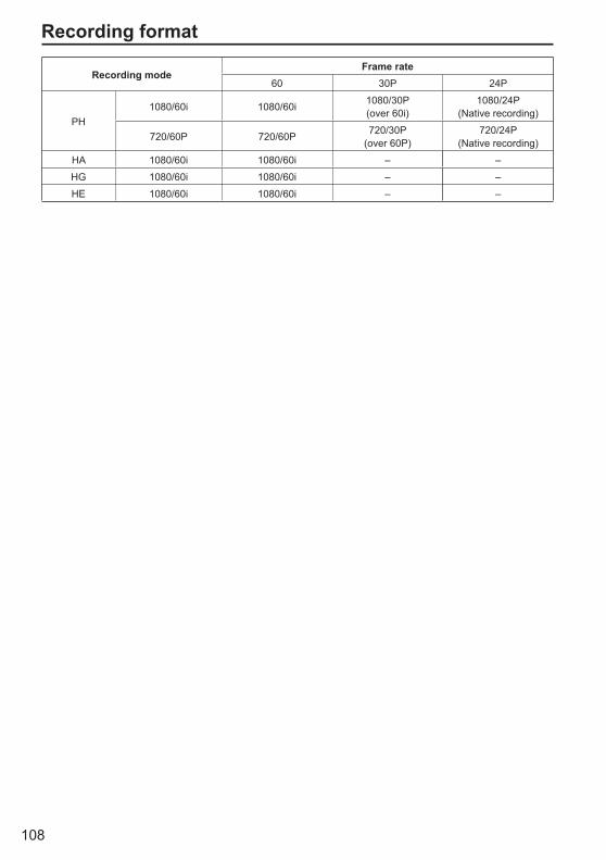
108
Recording format
Recording modeFrame rate
60 30P 24P
PH1080/60i 1080/60i 1080/30P
(over 60i)1080/24P
(Native recording)
720/60P 720/60P 720/30P(over 60P)
720/24P(Native recording)
HA 1080/60i 1080/60i – –
HG 1080/60i 1080/60i – –
HE 1080/60i 1080/60i – –
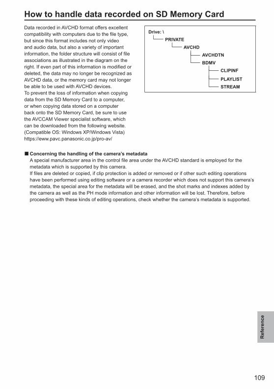
109
Ref
eren
ce
How to handle data recorded on SD Memory CardData recorded in AVCHD format offers excellent compatibility with computers due to the file type, but since this format includes not only video and audio data, but also a variety of important information, the folder structure will consist of file associations as illustrated in the diagram on the right. If even part of this information is modified or deleted, the data may no longer be recognized as AVCHD data, or the memory card may not longer be able to be used with AVCHD devices.To prevent the loss of information when copying data from the SD Memory Card to a computer, or when copying data stored on a computer back onto the SD Memory Card, be sure to use the AVCCAM Viewer specialist software, which can be downloaded from the following website. (Compatible OS: Windows XP/Windows Vista)https://eww.pavc.panasonic.co.jp/pro-av/
Drive: \PRIVATE
AVCHDAVCHDTNBDMV
CLIPINF
PLAYLISTSTREAM
Concerning the handling of the camera’s metadata A special manufacturer area in the control file area under the AVCHD standard is employed for the
metadata which is supported by this camera. If files are deleted or copied, if clip protection is added or removed or if other such editing operations
have been performed using editing software or a camera recorder which does not support this camera’s metadata, the special area for the metadata will be erased, and the shot marks and indexes added by the camera as well as the PH mode information and other information will be lost. Therefore, before proceeding with these kinds of editing operations, check whether the camera’s metadata is supported.
■

110
Specifications[General]
Supply voltage: DC 7.2 V (when the battery is used)/7.3 V (when the AC adapter is used)
Power consumption: Recording: 9.8 W
indicates safety information.
Ambient operating temperature 0 °C to 40 °C (32 °F to 104 °F)Ambient operating humidity 10% to 80% (no condensation)Weight Approx. 1.7 k (3.7 lb)
(excluding battery and accessories)Dimensions (W x H x D) 154 mm × 164 mm × 397 mm (6-1/16 inches × 6-15/32 inches × 15-5/8 inches)
(excluding the projection part)
[Camera]Pickup devices CCD image sensor (× 3)
(1/3-inch, interline transfer, progressive-capable)Lens LEICA DICOMAR Optical image stabilizer lens,
Motorized/Manual selectable 13 x zoom, F1.6 to F3.0 (f=3.9 mm to 51 mm)(35 mm equivalent: 28 mm to 368 mm)
Color separation optical system Prism systemND filter 1/4, 1/16, 1/64Gain settings 0/+3/+6/+9/+12/+18 dB (60i/60P mode) • 1/15 (0 dB) (in slow shutter mode) 0/+3/+6/+9/+12 dB (30P/24P mode) • 1/15 (0 dB) (in slow shutter mode)Shutter speed settings Preset 60i/60P mode: 1/60(OFF), 1/100, 1/120, 1/250, 1/500,
1/1000, 1/2000 seconds 30P mode: 1/30, 1/50 (OFF), 1/60, 1/120, 1/250,
1/500, 1/1000 seconds 24P mode: 1/24, 1/50 (OFF), 1/60, 1/120, 1/250,
1/500, 1/1000 seconds Synchronous scan settings 60i/60P mode: 1/60.0 seconds to 1/249.8
seconds 30P mode: 1/30.0 seconds to 1/249.8 seconds 24P mode: 1/24.0 seconds to 1/249.8 seconds
Slow shutter speed settings 60i/60P mode: 1/15, 1/30 seconds 30P mode: 1/15 secondsMinimum subject luminance 3 lx (F1.6, gain +12 dB, with a shutter speed of
1/24)Digital zoom 2 x /5 x /10 x (Assigned to the USER button, for
switching zoom levels) Operation with the 1080/60i and 720/60P
formats onlyLens hood Large-sized lens hood with wide angle of viewFilter diameter 72 mm
[Recording/playback]Recording Format AVCHD specificationsCompression method MPEG-4 AVC/H.264Recording media SD Memory Card: 512 MB, 1 GB, 2 GB
(FAT12 and FAT16 format) SDHC Memory Card: 4 GB, 6 GB, 8 GB, 12 GB, 16 GB, 32 GB
(FAT32 format) SD/SDHC Memory Cards with a memory size
from 8 MB to 32 GB can be used to record and read scene files and user files and to read metadata.
Recording format (Recording mode: resolution) PH mode: 1080/60i
1080/30P (over 60i)1080/24P (Native recording)720/60P720/30P (over 60P)720/24P (Native recording)
HA mode: 1080/60i HG mode: 1080/60i HE mode: 1080/60iTransmission rate PH mode: Approx. 21 Mbps (VBR) HA mode: Approx. 17 Mbps (VBR) HG mode: Approx. 13 Mbps (VBR) HE mode: Approx. 6 Mbps (VBR)
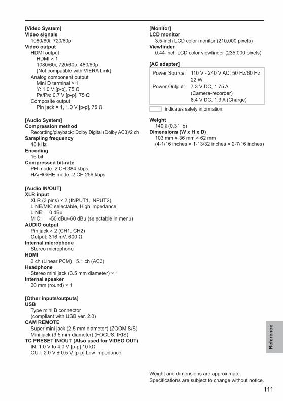
111
Ref
eren
ce
[Video System]Video signals 1080/60i, 720/60pVideo output HDMI output HDMI × 1 1080/60i, 720/60p, 480/60p
(Not compatible with VIERA Link) Analog component output Mini D terminal × 1 Y: 1.0 V [p-p], 75 Ω PB/PR: 0.7 V [p-p], 75 Ω Composite output Pin jack × 1, 1.0 V [p-p], 75 Ω
[Audio System]Compression method Recording/playback: Dolby Digital (Dolby AC3)/2 chSampling frequency 48 kHzEncoding 16 bitCompressed bit-rate PH mode: 2 CH 384 kbps HA/HG/HE mode: 2 CH 256 kbps
[Audio IN/OUT]XLR input XLR (3 pins) × 2 (INPUT1, INPUT2), LINE/MIC selectable, High impedance
LINE: 0 dBu MIC: -50 dBu/-60 dBu (selectable in menu)AUDIO output Pin jack × 2 (CH1, CH2) Output: 316 mV, 600 ΩInternal microphone Stereo microphoneHDMI 2 ch (Linear PCM) · 5.1 ch (AC3)Headphone Stereo mini jack (3.5 mm diameter) × 1Internal speaker 20 mm (round) × 1
[Other inputs/outputs]USB Type mini B connector
(compliant with USB ver. 2.0)CAM REMOTE Super mini jack (2.5 mm diameter) (ZOOM S/S) Mini jack (3.5 mm diameter) (FOCUS, IRIS)TC PRESET IN/OUT (Also used for VIDEO OUT) IN: 1.0 V to 4.0 V [p-p] 10 kΩ OUT: 2.0 V ± 0.5 V [p-p] Low impedance
[Monitor]LCD monitor 3.5-inch LCD color monitor (210,000 pixels)Viewfinder 0.44-inch LCD color viewfinder (235,000 pixels)
[AC adapter]
Power Source: 110 V - 240 V AC, 50 Hz/60 Hz 22 W
Power Output: 7.3 V DC, 1.75 A (Camera-recorder)
8.4 V DC, 1.3 A (Charge)
indicates safety information.
Weight 140 (0.31 lb)Dimensions (W x H x D) 103 mm × 36 mm × 62 mm
(4-1/16 inches × 1-13/32 inches × 2-7/16 inches)
Weight and dimensions are approximate. Specifications are subject to change without notice.

Information on Disposal in other Countries outside the European Union
This symbol is only valid in the European Union. If you wish to discard this product, please contact your local authorities or dealer and ask for the correct method of disposal.
P
Panasonic Broadcast & Television Systems CompanyUnit Company of Panasonic Corporation of North America
Executive Office: One Panasonic Way 4E-7, Secaucus, NJ 07094 Tel: 201-348-7000Eastern Zone: One Panasonic Way 4E-7, Secaucus, NJ 07094 Tel: 201-348-7196
Southeast Region: Tel: 201-392-6151Western Zone: 3330 Cahuenga Blvd W., Los Angeles, CA 90068 Tel: 323-436-3608Government Marketing Department:
One Panasonic Way 2E-10, Secaucus, NJ 07094 Tel: 201-348-7587Broadcast PARTS INFORMATION & ORDERING:
9:00 a.m. – 5:00 p.m. (EST) Tel: 800-334-4881/24 Hr. Fax: 800-334-4880Emergency after hour parts orders Tel: 800-334-4881e-mail: [email protected]
TECHNICAL SUPPORT: Emergency 24 Hour Service Tel: 800-222-0741e-mail: [email protected]
Panasonic Canada Inc.5770 Ambler Drive, Mississauga, Ontario L4W 2T3 Tel: 905-624-5010
Panasonic de México S.A. De C.V.Casa Matriz: Moras No.313 Col. Tlacoquemecatl Del Valle Del.Benito Juárez México, D.F., C.P.03200Tel: 55-5488-1000 Fax: 55-5575-6783
Panasonic Latin America, S.A.P.O.Box 0816-03164 Panama, Republic of Panama Tel: +507-229-2955 Fax: 507-229-5352
Panasonic do Brasil Ltda.Rua Cubatão, 320-6o andar-Paraíso CEP 04013-001- São Paulo -SP Tel: 11-3889-4000 Fax: 11-3889-4004
2008 Matsushita Electric Industrial Co., Ltd. All Rights Reserved.