Memo 498
8
* The Atacama Large Millimeter Array (ALMA) is an international astronomy facility. ALMA is an equal partnership between Europe and North America, in cooperation with the Republic of Chile, and is funded in North America by the U.S. National Science Foundation (NSF) in cooperation with the National Research Counci l of Canada (NRC), and in Europe by the European Southern Observatory (E SO) and Spain. ALMA construction and operations are led on behalf of North America by the National Radio Astronomy Observatory (NR AO), which is managed by Associated Universities, Inc. (AUI), and on behalf of Europe by ESO. Presented at the 2004 International Symposium on Space THz Technology, Northampton, MA, April 2004 http://www.alma.nrao.edu/memos/ ALMA Memo 498 14 May 2004 The ALMA Band 6 (211-275 GHz) Sideband- Separating SIS Mixer-Preamplifier A. R. Kerr 1 , S.-K. Pan 1 , E. F. Lauria 1 , A. W. Lichtenberger 2 , J. Zhang 2 M. W. Pospieszalski 1 , N. Horner 1 , G. A. Ediss 1 , J. E. Effland 1 , R. L. Groves 1 1 National Radio Astronomy Observatory Charlottesville, VA 22903 2 The University of Virginia Charlottesville, VA 22904 ABSTRACT The ALMA Band 6 (211-275 GHz) receivers use sideband-separating SIS mixer-preamplifiers with dual 4-12 GHz IF outputs. The sideband-separating mixers are of the phasing type, with the LO driving two component mixers in-phase and the RF signal connected to the mixers through a quadrature hybrid. The IF outputs of the mixers are amplified, then combined in a quadrature h ybrid which separates the upper and lower sideb and signals. The RF circuit components are all in a single split waveguide block — quadrature hybrid, LO power divider, LO couplers, cold image termination, and the two mixer chips. To achieve the wide IF bandwidth, a low-parasitic mixer is used and the preamps are bolted directly to the mixer block. INTRODUCTION The Atacama Large Millimeter Array * will have 64 antennas and will cover 35-960 GHz in ten bands using dual-polarized heterodyne receivers. In Band 6 (211-275 GHz), sideband-separating SIS mixers with dual 4-12 GHz IF outputs are used. Sideband separation (or rejection) in the front end is desirable for spectral line observations to reduce the contribution of atmospheric noise in the imag e sideband to the overall system noise . There are three ways to suppress the image response of a broadban d mixer receiver: (i) A filter can be inserted in front of the mixer to terminate the mixer reactively at the image frequency. This is difficult in widely tunable receivers. (ii) A tunable four-port diplexer with a cold image termination can be used. This can be done quasioptically, e.g., using a Martin-Puplett interferometer, but has li mited IF fractional bandwith, requires mechanical tuning, and is cumbersome at millimeter wavelengths. (iii) A sideband-separating mixer can be used, and this is the approach used in the present work. Different approaches to sideband separation are described in [1]. At the 1998 ISSTT, we described a single-chip Band 6 sideband-separating mixer [2], and in 2000 proposed a waveguide version of a similar circuit but with balanced mixers [3]. Other waveguide based sideband-separating SIS mixers have been des cribed by Claude et al. [4], Belitsky et al. [5], and Chin et al. [6]. The configuration used in the present work is shown s chematically in Fig. 1. Of particular importance in Fig. 1 is the resistor R IM on the fourth port of the RF quadrature hybrid. From the symmetry of the circuit, it is clear that this resistor is the image source for the sideband-separating mixer; USB thermal noise from this resistor is downconverted to the LSB IF output port, while LSB thermal noise appears at the USB IF output. MIXER CIRCUIT DESIGN Although a single-chip design with all t he RF components on the same substrate may seem attractive, the large size of the chip compared with that of a simple elemental mixer results in a relatively small number of mixers per wafer. As ALMA requires well over 100 mixers for each band, we explored the feasibility of machining the RF components as waveguide circuits in a single E-plane split metal block which also contains two elemental mixer chips. The most difficult component to fabricate with acceptable gain and phase imbalance is the waveguide quadrature hybrid, but this
-
Upload
abhay-kulkarni -
Category
Documents
-
view
218 -
download
0
Transcript of Memo 498

7/25/2019 Memo 498
http://slidepdf.com/reader/full/memo-498 1/8
* The Atacama Large Millimeter Array (ALMA) is an international astronomy facility. ALMA is an equal partnership between Europe and
North America, in cooperation with the Republic of Chile, and is funded in North America by the U.S. National Science Foundation (NSF) in cooperationwith the National Research Council of Canada (NRC), and in Europe by the European Southern Observatory (ESO) and Spain. ALMA constructionand operations are led on behalf of North America by the National Radio Astronomy Observatory (NRAO), which is managed by AssociatedUniversities, Inc. (AUI), and on behalf of Europe by ESO.
Presented at the 2004 International Symposium on Space THz Technology, Northampton, MA, April 2004 http://www.alma.nrao.edu/memos/
ALMA Memo 49814 May 2004
The ALMA Band 6 (211-275 GHz) Sideband-
Separating SIS Mixer-PreamplifierA. R. Kerr 1, S.-K. Pan 1, E. F. Lauria 1, A. W. Lichtenberger 2, J. Zhang 2
M. W. Pospieszalski 1, N. Horner 1, G. A. Ediss 1, J. E. Effland 1, R. L. Groves 1
1 National Radio Astronomy Observatory
Charlottesville, VA 22903
2 The University of Virginia
Charlottesville, VA 22904
ABSTRACT
The ALMA Band 6 (211-275 GHz) receivers use sideband-separating SIS mixer-preamplifiers with dual 4-12
GHz IF outputs. The sideband-separating mixers are of the phasing type, with the LO driving two component mixers
in-phase and the RF signal connected to the mixers through a quadrature hybrid. The IF outputs of the mixers are
amplified, then combined in a quadrature hybrid which separates the upper and lower sideband signals. The RF circuit
components are all in a single split waveguide block — quadrature hybrid, LO power divider, LO couplers, cold image
termination, and the two mixer chips. To achieve the wide IF bandwidth, a low-parasitic mixer is used and the preamps
are bolted directly to the mixer block.
INTRODUCTION
The Atacama Large Millimeter Array* will have 64 antennas and will cover 35-960 GHz in ten bands using
dual-polarized heterodyne receivers. In Band 6 (211-275 GHz), sideband-separating SIS mixers with dual 4-12 GHz
IF outputs are used. Sideband separation (or rejection) in the front end is desirable for spectral line observations to
reduce the contribution of atmospheric noise in the image sideband to the overall system noise. There are three ways
to suppress the image response of a broadband mixer receiver: (i) A filter can be inserted in front of the mixer to
terminate the mixer reactively at the image frequency. This is difficult in widely tunable receivers. (ii) A tunable
four-port diplexer with a cold image termination can be used. This can be done quasioptically, e.g., using aMartin-Puplett interferometer, but has limited IF fractional bandwith, requires mechanical tuning, and is cumbersome
at millimeter wavelengths. (iii) A sideband-separating mixer can be used, and this is the approach used in the present
work. Different approaches to sideband separation are described in [1]. At the 1998 ISSTT, we described a single-chip
Band 6 sideband-separating mixer [2], and in 2000 proposed a waveguide version of a similar circuit but with balanced
mixers [3]. Other waveguide based sideband-separating SIS mixers have been described by Claude et al. [4], Belitsky
et al. [5], and Chin et al. [6]. The configuration used in the present work is shown schematically in Fig. 1. Of particular
importance in Fig. 1 is the resistor R IM on the fourth port of the RF quadrature hybrid. From the symmetry of the circuit,
it is clear that this resistor is the image source for the sideband-separating mixer; USB thermal noise from this resistor
is downconverted to the LSB IF output port, while LSB thermal noise appears at the USB IF output.
MIXER CIRCUIT DESIGN
Although a single-chip design with all the RF components on the same substrate may seem attractive, the large
size of the chip compared with that of a simple elemental mixer results in a relatively small number of mixers per wafer.
As ALMA requires well over 100 mixers for each band, we explored the feasibility of machining the RF components
as waveguide circuits in a single E-plane split metal block which also contains two elemental mixer chips. The most
difficult component to fabricate with acceptable gain and phase imbalance is the waveguide quadrature hybrid, but this

7/25/2019 Memo 498
http://slidepdf.com/reader/full/memo-498 2/8
1 Cutting Edge Technologies/Richards Micro-Tool, Inc., 250 Nicks Road, Plymouth, MA 02360.
-2-
Fig. 1. Sideband-separating mixer configuration used for Band 6.
is possible using a branch-line coupler machined with a small (0.004" diameter) end-mill1 with long (0.020") working
depth. The quadrature hybrid is similar to those described in [7]. The LO power splitter is a matched E-plane T-junction
[8]. Cross-guide and broad-wall hole-coupled waveguide directional couplers, commonly used for LO injection, are not
suitable for E-plane split block circuits. Instead, the LO couplers use multiple broad-wall coupling probes [9] [10]; the
coupling can be changed from 22 dB to 18 dB by using six probes instead of four. The waveguide loads on the LO
couplers and the RF hybrid must be compact but well matched at the 4 K operating temperature; their design is described
in [11]. Geometrical constraints imposed by the preamplifiers and the magnetic circuit make it desirable for the signal
and LO input waveguides to enter the mixer perpendicular to the plane of the split between the halves of the block. This
requires a well matched H-plane bend, as described in [8]. Bias to the elemental mixers is provided through the IF
preamplifiers as in [12], which eliminates the need for a separate bias connector on the mixer block and also allows the
preamps to be mounted closer to the mixer chips. Figure 2 shows one half of the mixer block. Figure 3 shows a front
view of the assembled mixer-preamp with the lids removed, and Fig. 4 shows a rear view of the assembly. The magnetic
pole pieces, visible in Fig. 3, are made of annealed Consumet magnet iron after the design described in [13] and [14].
Fig. 2. One half of the mixer block. At the top are the cold image termination [11] and the signal input waveguide which entersfrom below the page via an H-plane bend [8]. The signal is split by the branch-line hybrid and passes to the mixer chips via
the LO couplers [9]. The LO power enters the lower waveguide from above the page via an H-plane bend, is divided by thematched T-junction [8] and is coupled to the mixers through the LO couplers.

7/25/2019 Memo 498
http://slidepdf.com/reader/full/memo-498 3/8
-3-
Fig. 3. Mixer-preamp assembly with the mixer and preamp lids removed. The Y-shaped magnetic pole pieces are visible in theupper and lower parts of the mixer block. The IF/DC connection between the mixer chips and the preamplifiers is by a (series)bond wire and (shunt) chip capacitor.
Fig. 4. Mixer-preamp assembly showing the LO input waveguide and the type-K IF connectors.
SIS MIXER DESIGN
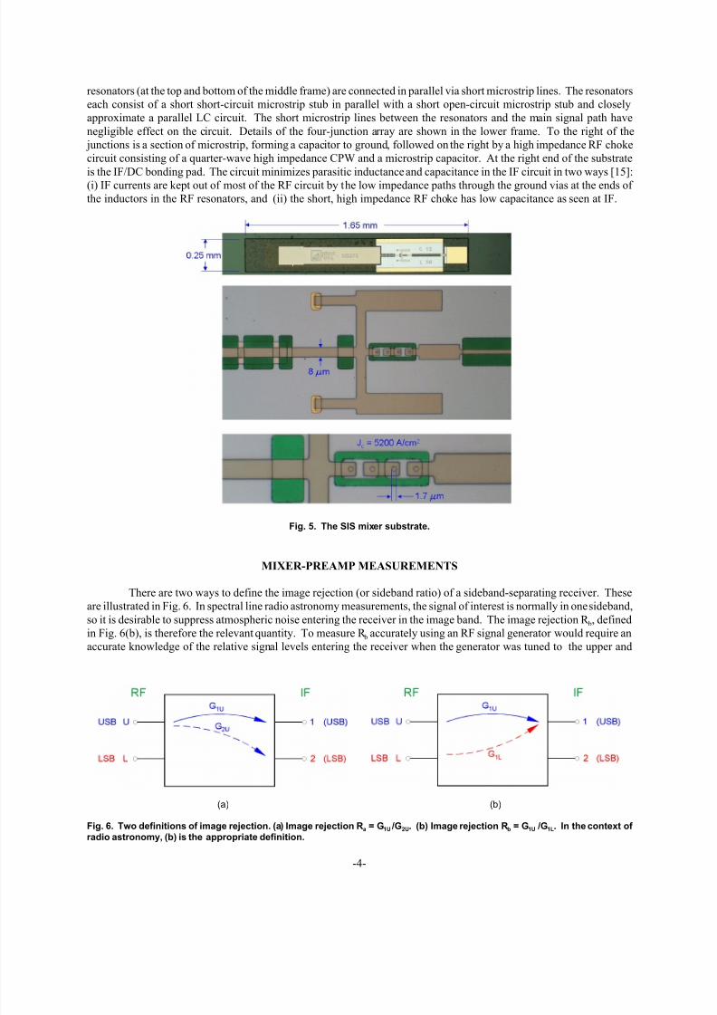
The elemental SIS mixers, shown in Fig. 5, are based on our earlier broadband wide-IF design [15]. The main
differences are the use of a quasi-lumped element tuning circuit in place of the quarter-wave short-circuit stubs in [15]
and a shorter RF choke to reduce parasitic capacitance and inductance in the IF circuit. The mixers are fabricated on
fused quartz substrates using the UVA Nb/Al-AlOx/Nb process [16], [17]. The upper frame of Fig. 5 shows the whole
mixer chip with the waveguide coupling probe on the left and a length of suspended stripline leading to a broadband
transition to capacitively-loaded coplanar waveguide (CLCPW) [1]. The Nb ground plane has gold contact pads (top
and bottom in the upper frame) which contact shoulders in the mixer block. The middle frame in Fig. 5 shows the end
of the CLCPW (at the left) connected to a short microstrip line and a short section of CPW. The microstrip and CPW
form a shunt-C/series-L impedance transformer. Between the CPW and the series array of four SIS junctions, a pair of
7/25/2019 Memo 498
http://slidepdf.com/reader/full/memo-498 4/8
-4-
(a) (b)
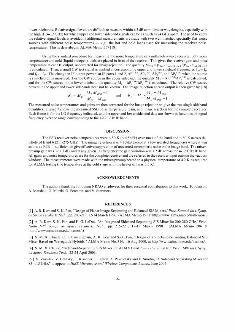
Fig. 6. Two definitions of image rejection. (a) Image rejection Ra = G1U /G2U. (b) Image rejection Rb = G1U /G1L. In the context of
radio astronomy, (b) is the appropriate definition.
resonators (at the top and bottom of the middle frame) are connected in parallel via short microstrip lines. The resonators
each consist of a short short-circuit microstrip stub in parallel with a short open-circuit microstrip stub and closely
approximate a parallel LC circuit. The short microstrip lines between the resonators and the main signal path have
negligible effect on the circuit. Details of the four-junction array are shown in the lower frame. To the right of the
junctions is a section of microstrip, forming a capacitor to ground, followed on the right by a high impedance RF choke
circuit consisting of a quarter-wave high impedance CPW and a microstrip capacitor. At the right end of the substrate
is the IF/DC bonding pad. The circuit minimizes parasitic inductance and capacitance in the IF circuit in two ways [15]:(i) IF currents are kept out of most of the RF circuit by the low impedance paths through the ground vias at the ends of
the inductors in the RF resonators, and (ii) the short, high impedance RF choke has low capacitance as seen at IF.
Fig. 5. The SIS mixer substrate.
MIXER-PREAMP MEASUREMENTS
There are two ways to define the image rejection (or sideband ratio) of a sideband-separating receiver. These
are illustrated in Fig. 6. In spectral line radio astronomy measurements, the signal of interest is normally in one sideband,
so it is desirable to suppress atmospheric noise entering the receiver in the image band. The image rejection R b, defined
in Fig. 6(b), is therefore the relevant quantity. To measure R b accurately using an RF signal generator would require an
accurate knowledge of the relative signal levels entering the receiver when the generator was tuned to the upper and

7/25/2019 Memo 498
http://slidepdf.com/reader/full/memo-498 5/8
-5-
Fig. 7. Measured SSB noise temperature, gain, and image rejection for the complete sideband-separating receiver with themixer-preamp at 4.2 K. Each frame is for the LO frequency indicated. The upper and lower sideband data are shown as
functions of signal frequency over the range corresponding to the 4-12 GHz IF band.
7/25/2019 Memo 498
http://slidepdf.com/reader/full/memo-498 6/8
-6-
lower sidebands. Relative signal levels are difficult to measure within ± 3 dB at millimeter wavelengths, especially with
the high IF (4-12 GHz) for which upper and lower sideband signals can be as much as 24 GHz apart. The need to know
the relative signal levels is avoided if additional measurements are made with two well matched spectrally flat noise
sources with different noise temperatures — e.g., the hot and cold loads used for measuring the receiver noise
temperature. This is described in ALMA Memo 357 [18].
Using the standard procedure for measuring the noise temperature of a millimeter-wave receiver, hot (roomtemperature) and cold (liquid nitrogen) loads are placed in front of the receiver. This gives the receiver gain and noise
temperature at each IF output, uncorrected for image rejection. The quantity MDSB = (Phot - Pcold)IF port 1 /(Phot - Pcold)IF port 2
is calculated. Then, a small CW test signal is applied at corresponding upper and lower sideband frequencies f LO + f IFand f LO - f IF. The change in IF output powers at IF ports 1 and 2,!P1
USB, !P2USB, !P1
LSB, and !P2LSB, when the source
is switched on is measured. For the CW source in the upper sideband, the quantity MU = !P1USB/!P2
USB is calculated,
and for the CW source in the lower sideband the quantity ML = !P1LSB/!P2
LSB is calculated. The relative CW source
powers in the upper and lower sidebands need not be known. The image rejection at each output is then given by [18]
and . R M M M
M M U
L DSB
U DSB
1
1! "
#
#
R M M M
M M L
U DSB
L DSB
2
1! "
#
#
The measured noise temperatures and gains are then corrected for the image rejection to give the true single sideband
quantities. Figure 7 shows the measured SSB noise temperature, gain, and image rejection for the complete receiver.
Each frame is for the LO frequency indicated, and the upper and lower sideband data are shown as functions of signal
frequency over the range corresponding to the 4-12 GHz IF band.
DISCUSSION
The SSB receiver noise temperatures were < 50 K (< 4.5hf/k) over most of the band and < 60 K across the
whole of Band 6 (211-275 GHz). The image rejection was > 10 dB except at a few isolated frequencies where it was
as low as 9 dB — sufficient to give effective suppression of unwanted atmospheric noise in the image band. The mixer-
preamp gain was 32 ± 3 dB, and at any given LO frequency the gain variation was ± 2 dB across the 4-12 GHz IF band.
All gains and noise temperatures are for the complete receiver and are referred to the receiver input outside the vacuum
window. The measurements were made with the mixer-preamp heated to a physical temperature of 4.2 K as required
for ALMA testing (the temperature at the cold stage with the heater off was 3.5 K).
ACKNOWLEDGMENTS
The authors thank the following NRAO employees for their essential contributions to this work: F. Johnson,
A. Marshall, G. Morris, G. Petencin, and V. Summers.
REFERENCES
[1] A. R. Kerr and S.-K. Pan, "Design of Planar Image-Separating and Balanced SIS Mixers," Proc. Seventh Int'l. Symp.
on Space Terahertz Tech., pp. 207-219, 12-14 March 1996. (ALMA Memo 151 at http://www.alma.nrao.edu/memos/.)
[2] A. R. Kerr, S.-K. Pan, and H. G. LeDuc, "An Integrated Sideband Separating SIS Mixer for 200-280 GHz," Proc.
Ninth Int'l. Symp. on Space Terahertz Tech., pp. 215-221, 17-19 March 1998. (ALMA Memo 206 at
http://www.mma.nrao.edu/memos/.)
[3] S. M. X. Claude, C. T. Cunningham, A. R. Kerr and S.-K. Pan, "Design of a Sideband-Separating Balanced SIS
Mixer Based on Waveguide Hybrids," ALMA Memo No. 316, 16 Aug 2000, at http://www.alma.nrao.edu/memos/.
[4] S. M. X. Claude, "Sideband-Separating SIS Mixer for ALMA Band 7 — 275-370 GHz," Proc. 14th Int'l. Symp.
on Space Terahertz Tech., 22-24 April 2003.
[5 ] V. Vassilev, V. Belitsky, C. Risacher, I. Lapkin, A. Pavolotsky and E. Sundin, "A Sideband Separating Mixer for
85–115 GHz," to appear in IEEE Microwave and Wireless Components Letters, June 2004.

7/25/2019 Memo 498
http://slidepdf.com/reader/full/memo-498 7/8
-7-
[6] C. C. Chin, D. Derdall, J. Sebesta, F. Jiang, P. Dindo, G. Rodrigues, D. Bond, S.-K. Pan, A. R. Kerr, E. Lauria, M.
Pospieszalski, J. Zhang, T. Cecil, and A. W. Lichtenberger, "A Low Noise 100 GHz Sideband-Separating Receiver,"
Int. J. Infrared and Millimeter Waves, vol. 25, no. 4, pp. 569-600, Apr. 2004.
[7] S. Srikanth and A. R. Kerr, “Waveguide Quadrature Hybrids for ALMA Receivers,” ALMA Memo 343, 11 Jan.
2001, http://www.alma.nrao.edu/memos/.
[8] A. R. Kerr, "Elements for E-Plane Split-Block Waveguide Circuits," ALMA Memo 381, 1 July 2001,
http://www.alma.nrao.edu/memos/.
[9] A. R. Kerr and N. Horner, "A Split-Block Waveguide Directional Coupler," ALMA Memo 432, 26 Aug. 2002,
http://www.alma.nrao.edu/memos/.
[10] A. R. Kerr, N. Horner, and V. Summers, "Fabrication of Small Metal Parts by Electroforming Through a
Photomask," NRAO Electronics Div. Tech. Note No. 194, 21 Jan. 2003, http://www.gb.nrao.edu/electronics/edtn/.
[11] A. R. Kerr, H. Moseley, E. Wollack, W. Grammer, G. Reiland, R. Henry, K. P. Stewart, "MF-112 and MF-116:
Compact Waveguide Loads and FTS Measurements at Room Temperature and 5 K," ALMA Memo 494, May 2004,
http://www.alma.nrao.edu/memos/.
[12] E. F. Lauria, A. R. Kerr, M. W. Pospieszalski, S.-K. Pan, J. E. Effland, and A. W. Lichtenberger, "A 200-300 GHz
SIS Mixer- Preamplifier with 8 GHz IF Bandwidth," 2001 IEEE International Microwave Symposium Digest , pp.
1645-1648, May 2001. (ALMA Memo 378, http://www.alma.nrao.edu/memos/.)
[13] G. A. Ediss and K. Crady, "Measurements of Materials for SIS Mixer Magnetic Circuits," ALMA Memo 438, 14
Nov. 2002, http://www.alma.nrao.edu/memos/.
[14] G. A. Ediss, "Calculations of Magnetic Circuits for SIS Mixers," National Radio Astronomy Observatory,
Electronics Division Technical Note No. 190, January 23, 2002, http://www.gb.nrao.edu/electronics/edtn/.
[15] A. R. Kerr, S.-K. Pan, A. W. Lichtenberger and H. H. Huang, "A Tunerless SIS Mixer for 200–280 GHz with Low
Output Capacitance and Inductance," Proceedings of the Ninth International Symposium on Space Terahertz Technology,
pp. 195-203, 17-19 March 1998. (ALMA Memo 205, http://www.alma.nrao.edu/memos/.)
[16] W. Clark, J. Z. Zhang and A. W. Lichtenberger, "Ti Quadlevel Resist Process for the Fabrication of Nb SIS
Junctions," IEEE Trans. Appl. Superconductivity, vol. 13, pp. 115-118, 2003.
[17] R. B. Bass, L. T. Lichtenberger, and A. W. Lichtenberger, "Effects of Substrate Preparation on the Stress of Nb
Thin Films," IEEE Trans. Appl. Superconductivity, vol. 13, pp. 3298-3300, 2003.[18] A. R. Kerr, S.-K. Pan and J. E. Effland, "Sideband Calibration of Millimeter-Wave Receivers,"
ALMA Memo #357, 27 March 2001, http://www.alma.nrao.edu/memos/.

7/25/2019 Memo 498
http://slidepdf.com/reader/full/memo-498 8/8