Membrane Separation Processes for Treatment of Hazardous …The membrane processes of cross-flow...
16
Membrane Separation Processesfor Treatment of Hazardous Waste Peter S. Cartwright Cartwright Consulting Co. ABSTRACT Industrial contaminants typically exist i.n one of the followimg forms: suspended solids, dissolved ionic, or dissolved organic materials. Often, these contaminants represent a health or safety hazard. As a result, these discharges are becoming imcreasingly regulated with an eye toward eventual elimination. The membrane processes of cross-flow microfiltration, ultrafi.ltration,and reverse osmosis offer excellent potential for continuous removal of these contaminants. The selection of the optimum process is a function of the form of the contaminants present as well as several other factors. Membrane separation technologi.es cannot make the contaminants disappear; however, they are extremely effective at concentrating the contaminants or "dewateri.ng" the stream i.n a pretreatment phase. In many cases the contaminant is merely a component from an industrial manufacturing operation that "escapes" from the process during a rinsing operation, or is purposely removed. This paper emphasizes the "point-of-source" concept of recycling or recoveri.ng specifi.c components for re-use through the application of membrane separation technologies. The fundamentals of these technologies are described, including membrane polymers and device confi.gurations,as well as complete system design considerations. 171
Transcript of Membrane Separation Processes for Treatment of Hazardous …The membrane processes of cross-flow...

Membrane Separation Processes for Treatment of Hazardous Waste
Peter S. Cartwright Cartwright Consulting Co.
ABS TRACT
Industrial contaminants typically exist i.n one of the followimg forms: suspended solids, dissolved ionic, or dissolved organic materials. Often, these contaminants represent a health or safety hazard. As a result, these discharges are becoming imcreasingly regulated with an eye toward eventual elimination.
The membrane processes of cross-flow microfiltration, ultrafi.ltration, and reverse osmosis offer excellent potential for continuous removal of these contaminants. The selection of the optimum process is a function of the form of the contaminants present as well as several other factors.
Membrane separation technologi.es cannot make the contaminants disappear; however, they are extremely effective at concentrating the contaminants or "dewateri.ng" the stream i.n a pretreatment phase.
In many cases the contaminant is merely a component from an industrial manufacturing operation that "escapes" from the process during a rinsing operation, or is purposely removed.
This paper emphasizes the "point-of-source" concept of recycling or recoveri.ng specif i.c components for re-use through the application of membrane separation technologies.
The fundamentals of these technologies are described, including membrane polymers and device confi.gurations, as well as complete system design considerations.
1 7 1

INTRODUCTION
There are many treatment technologies available today to either remove contaminants from industrial streams or render the contaminants harmless.
The following table lists processes that are currently in use to remove contaminants from water supplies:
Biological Processes Activated sludge Anaerobic digestion Bio-filters Extended aeration Bio-denitrif icatj.on Bio-nitrification Pasveer oxidation ditch
Chemical processes Chemical oxidation Catalytic oxidation Chlorination Ozona t ion Wet oxidation Chemical precipitation Chemical reduction Coagulation Inorganic chemicals Polyelectrolytes
Electrodialysis Electrolysis
Ion exchange Liquid-liquid (solvent)
Fluidized-bed Physical processes Carbon adsorption Granular activated Powdered
Distillation Filtration
Disinfection Electrolytic processes
Extractions
Incineration
Diatomaceous-earth fi 1 tration
Dual-media filtration Micro-screening Sand filtration
sedimentation Flocculation-
Foam separation Freezing
Suspended Dissolved Col1,oidal Dissolved Micro-
BOD Sol ids Inorganic organism Remova I Remova 1 Remova 1 Removal
X X X
L X X
X X -
X
X X X
172

(continued)
S u spended
Sol. ids Dissolved Colloidal Dissolved Micro-
BOD I no 1: g a n i. c or ga n i s m Remova 1 Remova 1 Remova i iiemova 1
MEMBRANE PROCESSING MICROFILTRATION - ULTRAFILTRATION X REVERSE OSMOSIS X Stripping (air or steam) x
X X X X
X X X -
L = Under specific conditions there will be limited effectiveness.
Figure One (1) illustrates the relationship of some of these techno1ogi.es to contaminant size range.
Membrane separation technologies offer the following advantages over competing processes:
-continuous processing (not batch) -low energy requirements (pumping only) -modular construction -simple maintenance demands -positive barrier to contaminants -ambient temperature operation
173

L i s t e d below are t h e membrane p r o c e s s e s recommended f o r t h e a p p r o p r i a t e contami.nant c a t e g o r y .
Contaminant Recommended Membrane P rocess
Suspended S o l i d s
>0.1 u <0.1 u
Dissolved S o l i d s
Organic 1oni.c
Microorganisms
M i c r o f i l t r a t i o n U l t r a f i.1 t r a t i o n
Ultraf i . l t ra t i .on/Reverse O s m o s i s Reverse O s m o s i s M i.cr o f i. 1 t r a t i on / U 1 t r a f i. 1 t r a t i on
BACKGROUND
A l l o f t h e membrane p r o c e s s e s u t i l i z e an e n g i n e e r i n g d e s i g n known a s "c ross - f l o w " o r " t angen t i . a l f low" f i l t r a t i o n . I n t h i s mechanism, t h e bu lk s o l u t i o n f lows over and p a r a l l e l t o t h e membrane s u r f a c e , and because t h e system i s p r e s s u r i z e d , water i s f o r c e d th rough t h e membrane. T h e t u r b u l e n t f low of t h e bu lk s o l u t i o n a c r o s s t h e s u r f a c e mimimizes t h e accumulati .on o f p a r t i c u l a t e matter on t h e membrane and f a c i l i t a t e s t h e con t inuous o p e r a t i o n of t h e system.
Fi .gure Two ( 2 ) i l l u s t r a t e s b o t h conventi .ona1 and c ross - f low mechanisms.
Con vc n t I o n a I Fi It r a t I o n
Particle-free permeate * Cross-flow Filtration
F i g u r e 2 , F i l t r a t i o n Mechanisms
174

Figure Three ( 3 ) illustrates the mechanism of cross flow microfiltrati.on. Microfi.ltrati.on involves the removal of insoluble particulate materials ranging in size from 0.1 to 10.0 microns (1000 to 100,000 angstroms). Microfiltration membrane polymers include:
-Polycarbonate -Polyester -Mixed esters of cellulose -Cellulose triacetate (CTA) -PTFE (polytetrafluoroethylene) -PVC (polyvinyl chloride) -Thin film composite (TFC) -Nylon
Figure 3 , Microfiltration
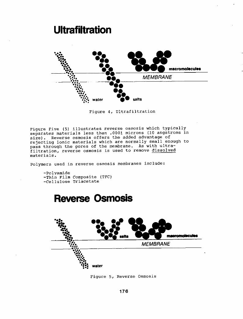
Fi.gure Four ( 4 ) depicts ultrafiltration, which is used to separate materi.als in the .001 to 0.1 micron range (10 to 1000 angstroms). Basically, Ultrafiltration i.s used to remove dissolved materials whereas suspended soli.ds are removed by microfiltration.
Typical polymers used include:
-Polysulfone -Cellulose Acetate -Polyamide
175
UI t raf il t rat ion
w. macromolecules
MEMBRANE .. water salts
Figure 4 , Ultraf i.ltrati.on
Figure Five (5) illustrates reverse osmosis which typically separates materials less than .0001 microns (10 angstroms i.n size). Reverse osmosis offers the added advantage of rejecting ionic materials which are normally small enough to pass through the pores of the membrane. As wi.th ultra- filtration, reverse osmosis is used to remove dissolved materi.als.
Polymers used in reverse osmosis membranes include:
-Po 1 yarni.de -Thin Film Composite (TFC) -Cellulose Triacetate
Reverse Osmosis
Figure 5, Reverse Osmosis
176

ELEMENT CONFIGURATIONS: The membrane can be "packaged" i n s e v e r a l e l emen t c o n f i . g u r a t i o n s , each o f f e r i n g p a r t i c u l a r advan tages depending on t h e a p p l i c a t i o n .
Tubular - Manufactured from ceramic, carbon, or any number of porous p l a s t i c s , t h e s e t u b e s have in.si.de diameters r a n g i n g from 1 / 8 i n c h up t o approximate ly 1 inch . The membrane i s t y p i c a l l y coated on t h e i n s i d e of t h e t u b e , and t h e f e e d s o l u t i o n f lows through t h e i n t e r i . o r from one end t o t h e o t h e r , w i t h t h e "permeate" or " f i l t r a t e " p a s s i n g th rough t h e w a l l t o be c o l l e c t e d on t h e o u t s i d e of t h e tube .
Hollow Fiber - Similar t o t h e t u b u l a r e l emen t s i.n d e s i g n , ho l low fibers are g e n e r a l l y much smaller i.n d i ame te r and r e q u i r e r i g i d s u p p o r t as i s o b t a i n e d from t h e " p o t t i n g " of a bundle i n s i d e a c y l i n d e r . Feed f low is e i t h e r down t h e i n t e r i o r o f t h e f iber o r around t h e o u t e r diameter.
S p i r a l Wound - This d e v i c e i.s c o n s t r u c t e d from an envelope o f s h e e t membrane wound around a permeate t u b e t h a t i s p e r f o r a t e d t o a l l o w c o l l e c t i . o n o f t h e permeate o r f i l t r a t e .
Plate and Frame - T h i s d e v i c e i n c o r p o r a t e s s h e e t membrane t h a t i s s t r e t c h e d ove r a frame t o s e p a r a t e t h e l a y e r s and f a c i l i t a t e c o l l e c t i o n of t h e permeate .
PLATE AND FRAME SPIRAL WOUND FEED IN
POROUS SHEET
MEMBRANE e CONCENTRATE OUT
SPACER PERMEATE OUT
FEED
ROLLTO
)
CONCENTRAT
- PERMEATE SIDE BACKING MATERIAL WlM MEMBRANE ON EACH SIDE AND GLUED AROUND EDGES TO CENTER TUBE
HOLLOW FIBER CONCENTRATE
TUBULAR r0 TUBE p " B F
- CONCENTRATE OUT
PERMEATE OUT
PERMEATE
F i g u r e 6 , Membrane Element Conf i .gurat i .ons
177

The followihg table summari.zes the important physical characteristics of the various membrane element device configurations available today:
Element Packing Suspended Solids Configuration Density Tolerance
Tubu 1 ar Low Hollow Fiber Highest Spir a 1 Wound High Plate and Frame Low
High Poor Fair High
*Membrane area per unit volume of space required.
Because of the propensity of suspended or precipitated materials to settle out on the membrane surface and plug the membrane pores, turbulent flow conditions must be maintained (Reynolds numbers in excess of 4000).
SYSTEM DESIGN CONSIDERATIONS
In order to treat an effluent stream, it must be thoroughly analyzed for the following data:
-Total solids content Suspended (TSS) Dissolved organic (TOC) Dissolved inorganic (TDS)
Oxidizing chemicals Organic solvents
-Spec i. f i.c chemic a 1 constituents
-Operating temperature -PH
Usually the goal is to "dewater" the feed system as much as possible; that is, to remove solvent to facilitate either re-use or removal of the concentrated solute. Of secondary importance i.s the possible re-use of the purified solvent (usually water). These two considerati.ons are significant in determining both the process and membrane device to be used.
Figure Seven ( 7 ) depicts a general schematic for membrane processes. In these technologies the implication of increasing the dewatering process i.s described by the term "recovery", which is defined as the purified water volume divided by the incoming stream volume; i.n other words, percentage of the feed flew which S.s pumped through the membrane. Typi.cally, for effluent treatment appli.cati.ons, the recovery figure is at least 90%. As recovery is increased (to decrease concentrated solute volume), the concentration of solute and suspended solids in the concentrate stream increases.
178

E f f l u e n t I Membrane I P u r i f i e d
Concent ra ted I S o l u t e
F i g u r e 7, Membrane P rocess Schematic
No membrane i s p e r f e c t i n t h a t i.t rejects 100% of t h e s o l u t e on t h e f e e d side; t h i s s o l u t e l eakage i s known as "passage". Expressed as " p e r c e n t pas sage" , t h e a c t u a l q u a n t i t y o f s o l u t e which p a s s e s through t h e membrane i s a f u n c t i o n of t h e c o n c e n t r a t i o n of s o l u t e on t h e f e e d s i d e . Under h i g h r e c o v e r y cond i t i . ons , t h e concen t r a t i . on of s o l u t e on t h e f e e d s i d e i s i n c r e a s e d and t h e r e f o r e t h e a c t u a l q u a n t i t y of s o l u t e passimg th rough t h e membrane a l s o i n c r e a s e s . Because most e f f l u e n t a p p l i c a t i o n s demand t h a t i n a d d i t i o n t o a minimum c o n c e n t r a t e volume, t h e permeate q u a l i t y be h i g h enough t o a l l o w re -use o r t o meet d i s c h a r g e r e g u l a t i o n s , t h e "Catch-22" predicament of permeate q u a l i t y d e c r e a s i n g as r e c o v e r y i s i n c r e a s e d can impose desi .gn l i m i t a t i o n s .
APPLICATIONS
Although membrane s e p a r a t i o n t e c h n o l o g i e s have found a p p l i c a t i o n s i n a number of s p e c i f i c areas, t h e p o t e n t i a l f o r t h e s e unique p r o c e s s e s has n o t y e t begun t o be tapped .
Fol lowing are d e s c r i p t i o n s of several s p e c i . f i c a p p l i c a t i o n s and case h i s t o r i e s i l l u s t r a t i n g w h e r e these p r o c e s s e s have been u t i l i z e d i.n i n d u s t r i a l e f f l u e n t t r e a t m e n t .
Metal F i n i s h i n g Trea tment
Point-of-Source Recovery - I n c e r t a i n c i r c u m s t a n c e s , it i s poss i . b l e t o u t i l i z e r e v e r s e osmosis t o e f f e c t a " z e r o d i s c h a r g e " e l e c t r o p l a t i n g r i n s e wa te r r ecove ry system. The r i n s e water from t h e f i r s t r i n s e i s pumped t o a r e v e r s e osmosis' sys tem t h a t c o n c e n t r a t e s t h e sa l t s and d i rec ts them back t o t h e p l a t i n g b a t h . The p u r i f i e d r i n s e water (permeate) i s directed t o t h e l a s t r i n s e , and n e i t h e r s o l u t e nor s o l v e n t i s l o s t . I n t h e United States there are approx ima te ly 150 r e v e r s e osmosis sys tems o p e r a t i n g i n t h i s manner on n i c k e l b a t h s and 1 2 on acid copper . There are a l s o a few i n s t a l l a t i o n s o p e r a t i n g on copper c y a n i d e , h e x a v a l a n t chrome, and acid z i n c .
179

Only those plating baths operating at relatively high temperatures (above 60 degrees Celsius), lend themselves to direct treatment by reverse osmosis. In most cases, the cost of the system is recovered by savings in plating salts within two years. Figure Eight (8) illustrates this application.
WORK FLOW * - - - - - - -
PLATING 1 TANK 1 Rinse R i n s e R i n s e
PERMEATE
REVERSE OSMOSIS
Figure 8 , "Zero Discharge" with Reverse Osmosis
"End of Pipe" Treatment - It is possi.ble to use reverse osmosis and ultrafiltrati.on to concentrate or "dewater" mi.xed effluent streams in order to reduce the hydraulic loading to down stream treatment processes. Typically, at least 90% of the feed volume can be purified and often returned to the process, with the salts concentrated in the remai.ning 10%.
Conventional chemical treatment of metal finishing wastes wi.ll usually produce clarified effluent acceptable for discharge; however, in those applicati.ons where it is desirable or necessary to recover the clarified rinse water for re-use, the technologies are utilized to purify or lldesaltll the effluent for re-use.
Microfi.ltration can be used to replace a clarifier in the chemical clarification of plating discharges. Compared to conventional equipment, it offers the advantages of continuous processing and si.gnificantly smaller space requirements. Figure Ni.ne (9) i.llustrates a microf iltration installation.
180

Eff luent Stream
Concentrat ion Tank
\ c
d \ . . . -. . I. .
Prec i p i t a t i n g Chemicals
Such as: Na borohydride Dithiocarbamates Hydrogen peroxide Insoluble Starch Xanthate
J. Sludge
F i g u r e 9 , M i c r o f i l t r a t i o n C l a r i f i . c a t i o n
Permeate 0 ischarge

Oily Waste Treatment - Oi.1-water emulsion effluent streams are typically generated as a result of the following industria 1 act i.vi. t i.e s :
-Metal cutting operations such as machining use oil-water emulsions for both lubrication and cooli.ng.
-Metal forming operations use oil-water emulsions for
-Hot and cold rolling operations for steel and aluminum lubrication.
strip utilize oil-water emulsions for both lubrication and cooling.
-Heat treatment/quenching processes generate oil-water emulsions during the process of removing oily contami.nants from metal parts.
Ultrafiltration can be utilized to separate the emulsion and dissolved oil from water. The specific ultrafiltration membrane polymer and pore-size requirement are determined by the oil chemistry; however, the oil can typically be concentrated up to 60 - 80%, and in some cases, incinerated to recover energy in the form of heat. The permeate stream may be pure enough to be re-used, or may require treatment with reverse osmosi.s pri.or to re-use.
Fi.gure Ten (10) illustrates the application of ultra- filtration to oily waste effluent treatment.
Printed Circuit Effluent Treatment
Because printed circuit products require higher quality rinse waters than typical electroplated products, demineralized water is often used, and there is economic justification for recovery of this more expensive water.
The heavy metals used in printed circuit electroless plating (copper and nickel) are in chelated form (chemically "tied-up" in an organic matrix). The plating baths are more unstable than electroplating baths, thereby resulting in more frequent "dumping". As a result, waste treatment requirements in printed circuit manufacturing operations present special problems and opportunities for membrane separation processes.
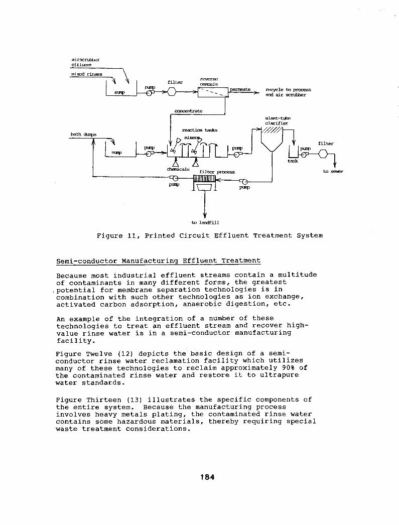
Figure Eleven (11) illustrates a total printed circuit effiuent treatment system utilizing reverse osmosis to recover purified water from mixed rinses and the airscrubber. Bath dumps and reverse osmosis concentrate are chemically treated, producing a sludge for landfilling and effluent suitable for discharge.
Membrane technologi.es can also be used in other parts of this total treatment system: microfiltration could be substituted for the clarifier (see Figure 9 ) , and reverse osmosis could purify the clarified effluent for re-use.
182

W
w(
3w
I
-a
m
WI
W
PU
PC
PC
m
w-
aa 3
no%
oa
c
-0
c 0
a, !..i 5
18
3
airrxrubber effluent
reverse filter osmsis
permeate . recycle to process sw - and air scrutrber
concentrate I
bath *S
T slant-tube clarifier
I reactiontanks &/////A , 1 1 1 ,
Y filter
tosewer
to landfill
Figure 11, Printed Circuit Effluent Treatment System
Semi-conductor Manufacturing Effluent Treatment
Because most industrial effluent streams contain a multitude of contaminants in many different forms, the greatest
combination with such other technologies as ion exchange, activated carbon adsorption, anaerobic digestion, etc.
,potential for membrane separation technologies is in
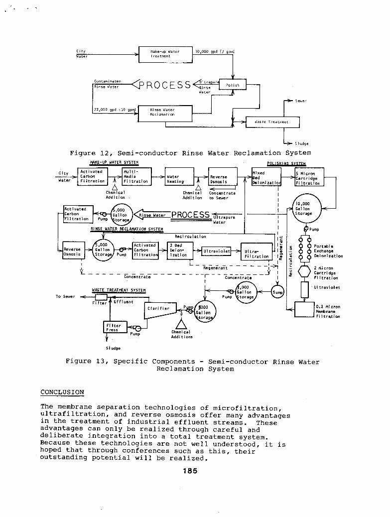
An example of the integration of a number of these technologies to treat an effluent stream and recover high- value rinse water is in a semi-conductor manufacturing f aci 1 ity . Figure Twelve (12) depicts the basic design of a semi.- conductor rinse water reclamation facility which utilizes many of these technologies to reclaim approximately 90% of the contaminated rinse water and restore it to ultrapure water standards.
Figure Thirteen (13) illustrates the specific components of the entire system. Because the manufacturing process involves heavy metals plating, the contaminated rinse water contains some hazardous materials, thereby requiring special waste treatment consi.derations.
184
Qater
Rinse Water Polish
Water
Rec I ama t i on
SI udge
Figure 12, Semi-conductor Rinse Water Reclamation System L R L w u p u MAKE-UP WATER SYSTEM
C i t y Ac t i va ted Mu l t i -
Water F i l t r a t i o n
1 - Mixed 5 Micron > Carbon Media -+- Water Reverse Bed e Cart r i dge
A F i l t r a t i o n F i l t r a t i o n Heating Osmor i s Dei oni zat lo r A L1
Chem i ca 1 Add i t ion
L A W Chem i ca I Concentrate Add i t ion to Sewer
I I I
Water I
Act iva ted Carbon
Rec i rcu la t ion
-.
To Sewer WASTE TREATMENT SYSTEM - k---Q+ Gal Ion .
Fi I t e r Press Chemi ca l
Addi t ions
U l t r a v i o l e t
SI udge
Figure 13, Specifi.c Components - Semi-conductor Ri.nse Water Reclamation System
CONCLUSION
The membrane separation technologies of microfiltration, ultrafiltration, and reverse osmosis offer many advantages in the treatment of industrial effluent streams. These advantages can only be realized through careful and deliberate integration into a total treatment system. Because these technologies are not well understood, i.t is hoped that through conferences such as this, their outstanding potential wi.11 be realized.
185

\
ste Reduction in the Electronic W. Hertz and Richard M. Holl asco Environmental Servic
Many e l e c t r o n i c companies i n t h e of a r s e n i c waste through t h e pro microchips. Since t h e concentra
undes i rab le environmental ly economically as ong-term mechanism f o r waste d i sposa l .
The Hewlett-Packard Com (HP) c u r r e n t l y ope ra t e gal l ium a r sen ide (GaAs)
a r s e n i c as w e l l as non-haz cons t i t uen t s . The
Other e l e c t r o n i c s i o n i s c u r r e n t l y n e u t r a l i z e d
t reatment s to rage and d i sposa l f a c i l i t y ( t s d f ) . I n 1985, g a l l o n s of pydro f luo r i c a c i d wastewater and 25,219 ga l lons
genera t ion . The information from Phase I w a s s u i scale t reatment f a c i l i t y .
inclhded, but were exchange, and a r s i n e t h e design of a p i l o t
186