MEMBER DESIGN - Steel Construction New Zealand ... · Disclaimer: SCNZ and the author(s) of this...
18
Disclaimer: SCNZ and the author(s) of this document make no warrantee, guarantee or representation in connection with this document and shall not be held liable or responsible for any loss or damage resulting from the use of this document Steel Advisor MEM6301 © Steel Construction New Zealand Inc. 2011 1 MEMBER DESIGN Design of Angle Trusses Author: Alistair Fussell Affiliation: Steel Construction New Zealand Inc. Date: 26 th August 2011 Ref.: MEM6301 Key Words Angle, effective length, truss, eccentric connections Introduction Angle sections are commonly used as members in light weight triangulated structures such as trusses and towers. The attraction of angle section is their ease of fabrication, they are however more complex to design than other types of structural sections. The reasons for this is the eccentricity of the common forms of end connections (figure 1) and also because the principal axes of a single angle do not coincide with the axis of the frame or truss of which the angle is a part (Temple et al, 1995). Figure 1: Angle strut gusset connection This article will cover the behaviour and design of angle struts, general principles of truss design and cost effective truss fabrication. Triangulated Angle Structures Triangulated angle structures are utilised in a range of building and bridge applications. These include roof, bridge and composite floor trusses (figure 2), and lateral restraint bracing for roof (figure 3a) and bridge beams (figure 3b). Angles are utilised in a number of arrangements for steel trusses. For lightweight trusses angles may be used for chord and web members while for heavily loaded trusses angles may only be used for the web elements with box sections, tees or channels used as chord members (figure 4). Tee sections are split from UB or UC sections. The web members can be a single member or double members, and they can be placed on the same side of the chord member or alternated. The cost and fabrication implications of these details will be discussed in section 7.0. Steel trusses may also be designed to act compositely with concrete slabs for floor applications. Good guidance on these types of structures is covered in the SCI publication Design of Composite Trusses (1992). These can be used both as primary and secondary floor support members.
Transcript of MEMBER DESIGN - Steel Construction New Zealand ... · Disclaimer: SCNZ and the author(s) of this...

Disclaimer: SCNZ and the author(s) of this document make no warrantee, guarantee or representation in connection with this
document and shall not be held liable or responsible for any loss or damage resulting from the use of this document Steel Advisor MEM6301 © Steel Construction New Zealand Inc. 2011 1
MEMBER DESIGN
Design of Angle Trusses Author: Alistair Fussell Affiliation: Steel Construction New Zealand Inc. Date: 26th August 2011 Ref.: MEM6301
Key Words
Angle, effective length, truss, eccentric connections
Introduction
Angle sections are commonly used as members in light weight triangulated structures such as trusses and towers. The attraction of angle section is their ease of fabrication, they are however more complex to design than other types of structural sections. The reasons for this is the eccentricity of the common forms of end connections (figure 1) and also because the principal axes of a single angle do not coincide with the axis of the frame or truss of which the angle is a part (Temple et al, 1995).
Figure 1: Angle strut gusset connection
This article will cover the behaviour and design of angle struts, general principles of truss design and cost effective truss fabrication.
Triangulated Angle Structures
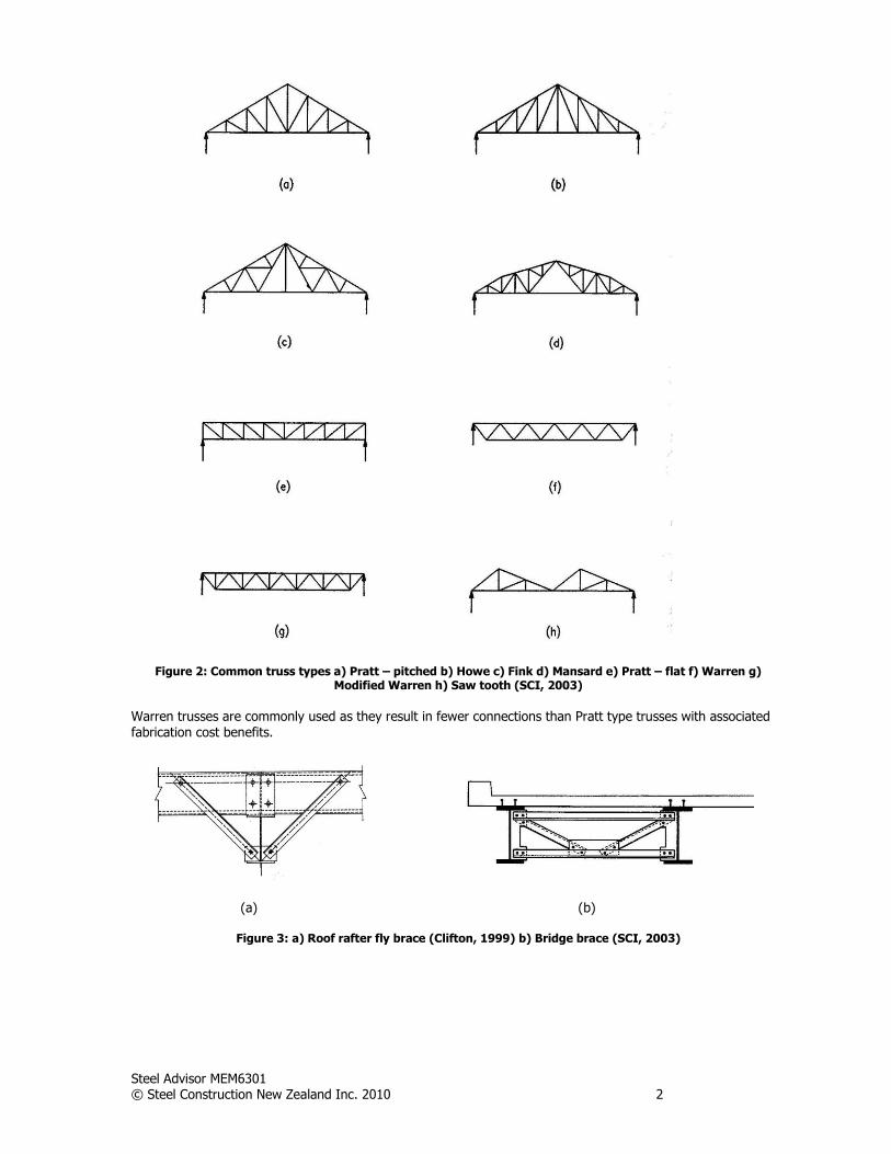
Triangulated angle structures are utilised in a range of building and bridge applications. These include roof, bridge and composite floor trusses (figure 2), and lateral restraint bracing for roof (figure 3a) and bridge beams (figure 3b). Angles are utilised in a number of arrangements for steel trusses. For lightweight trusses angles may be used for chord and web members while for heavily loaded trusses angles may only be used for the web elements with box sections, tees or channels used as chord members (figure 4). Tee sections are split from UB or UC sections. The web members can be a single member or double members, and they can be placed on the same side of the chord member or alternated. The cost and fabrication implications of these details will be discussed in section 7.0. Steel trusses may also be designed to act compositely with concrete slabs for floor applications. Good guidance on these types of structures is covered in the SCI publication Design of Composite Trusses (1992). These can be used both as primary and secondary floor support members.
Steel Advisor MEM6301 © Steel Construction New Zealand Inc. 2010 2
Figure 2: Common truss types a) Pratt – pitched b) Howe c) Fink d) Mansard e) Pratt – flat f) Warren g) Modified Warren h) Saw tooth (SCI, 2003)
Warren trusses are commonly used as they result in fewer connections than Pratt type trusses with associated fabrication cost benefits.
(a) (b)
Figure 3: a) Roof rafter fly brace (Clifton, 1999) b) Bridge brace (SCI, 2003)
Steel Advisor MEM6301 © Steel Construction New Zealand Inc. 2010 3
Figure 4: Truss arrangements (SCI, 1992)
Features of Truss Structures
Advantages
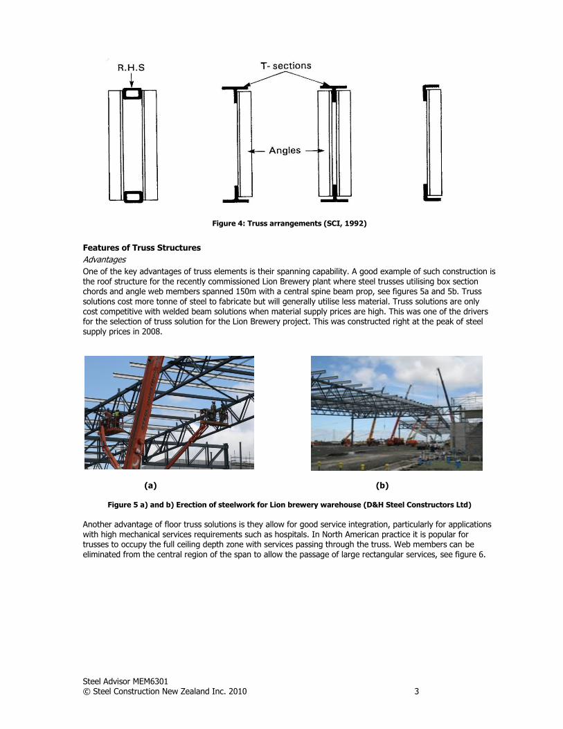
One of the key advantages of truss elements is their spanning capability. A good example of such construction is the roof structure for the recently commissioned Lion Brewery plant where steel trusses utilising box section chords and angle web members spanned 150m with a central spine beam prop, see figures 5a and 5b. Truss solutions cost more tonne of steel to fabricate but will generally utilise less material. Truss solutions are only cost competitive with welded beam solutions when material supply prices are high. This was one of the drivers for the selection of truss solution for the Lion Brewery project. This was constructed right at the peak of steel supply prices in 2008.
(a) (b)
Figure 5 a) and b) Erection of steelwork for Lion brewery warehouse (D&H Steel Constructors Ltd)
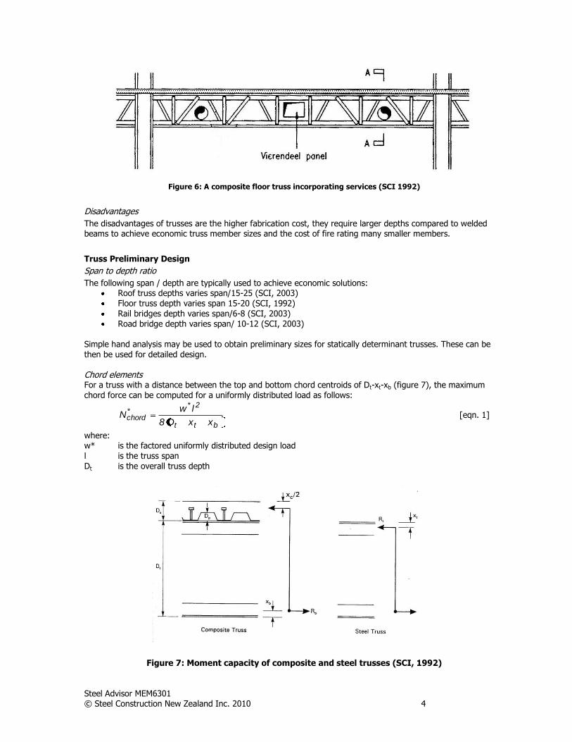
Another advantage of floor truss solutions is they allow for good service integration, particularly for applications with high mechanical services requirements such as hospitals. In North American practice it is popular for trusses to occupy the full ceiling depth zone with services passing through the truss. Web members can be eliminated from the central region of the span to allow the passage of large rectangular services, see figure 6.
Steel Advisor MEM6301 © Steel Construction New Zealand Inc. 2010 4
Figure 6: A composite floor truss incorporating services (SCI 1992)
Disadvantages
The disadvantages of trusses are the higher fabrication cost, they require larger depths compared to welded beams to achieve economic truss member sizes and the cost of fire rating many smaller members.
Truss Preliminary Design
Span to depth ratio
The following span / depth are typically used to achieve economic solutions: Roof truss depths varies span/15-25 (SCI, 2003) Floor truss depth varies span 15-20 (SCI, 1992) Rail bridges depth varies span/6-8 (SCI, 2003) Road bridge depth varies span/ 10-12 (SCI, 2003)
Simple hand analysis may be used to obtain preliminary sizes for statically determinant trusses. These can be
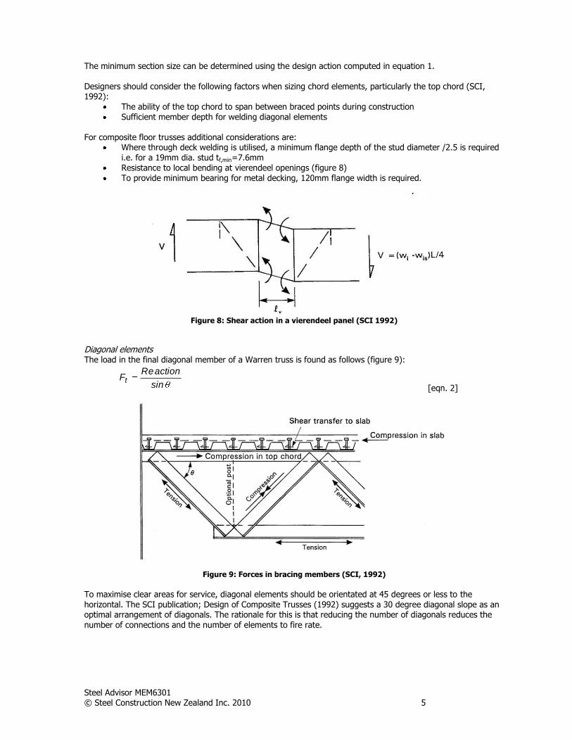
then be used for detailed design. Chord elements For a truss with a distance between the top and bottom chord centroids of Dt-xt-xb (figure 7), the maximum chord force can be computed for a uniformly distributed load as follows:
btt
2**chord
xxD8
lwN [eqn. 1]
where: w* is the factored uniformly distributed design load l is the truss span Dt is the overall truss depth
Figure 7: Moment capacity of composite and steel trusses (SCI, 1992)
Steel Advisor MEM6301 © Steel Construction New Zealand Inc. 2010 5
The minimum section size can be determined using the design action computed in equation 1. Designers should consider the following factors when sizing chord elements, particularly the top chord (SCI, 1992):
The ability of the top chord to span between braced points during construction Sufficient member depth for welding diagonal elements
For composite floor trusses additional considerations are:
Where through deck welding is utilised, a minimum flange depth of the stud diameter /2.5 is required i.e. for a 19mm dia. stud tf,min=7.6mm
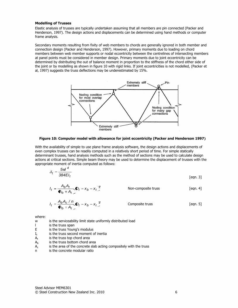
Resistance to local bending at vierendeel openings (figure 8) To provide minimum bearing for metal decking, 120mm flange width is required.
Figure 8: Shear action in a vierendeel panel (SCI 1992)
Diagonal elements The load in the final diagonal member of a Warren truss is found as follows (figure 9):
sin
actionReFt
[eqn. 2]
Figure 9: Forces in bracing members (SCI, 1992)
To maximise clear areas for service, diagonal elements should be orientated at 45 degrees or less to the horizontal. The SCI publication; Design of Composite Trusses (1992) suggests a 30 degree diagonal slope as an optimal arrangement of diagonals. The rationale for this is that reducing the number of diagonals reduces the
number of connections and the number of elements to fire rate.
Steel Advisor MEM6301 © Steel Construction New Zealand Inc. 2010 6
Modelling of Trusses
Elastic analysis of trusses are typically undertaken assuming that all members are pin connected (Packer and Henderson, 1997). The design actions and displacements can be determined using hand methods or computer frame analysis. Secondary moments resulting from fixity of web members to chords are generally ignored in both member and connection design (Packer and Henderson, 1997). However, primary moments due to loading on chord members between web member supports or nodal eccentricity between the centrelines of intersecting members at panel points must be considered in member design. Primary moments due to joint eccentricity can be determined by distributing the out of balance moment in proportion to the stiffness of the chord either side of the joint or by modelling as shown in figure 10 with rigid links. If joint eccentricities is not modelled, (Packer et al, 1997) suggests the truss deflections may be underestimated by 15%.
Figure 10: Computer model with allowance for joint eccentricity (Packer and Henderson 1997)
With the availability of simple to use plane frame analysis software, the design actions and displacements of even complex trusses can be readily computed in a relatively short period of time. For simple statically determinant trusses, hand analysis methods such as the method of sections may be used to calculate design actions at critical sections. Simple beam theory may be used to determine the displacement of trusses with the appropriate moment of inertia computed as follows:
t
4
tEI384
wl5
[eqn. 3]
2tbt
tb
tbt xxD
AA
AAI
Non-composite truss [eqn. 4]
2tbt
tb
cbt xxD
AA
n/AAI
Composite truss
[eqn. 5]
where: w is the serviceability limit state uniformly distributed load l is the truss span E is the truss Young’s modulus It is the truss second moment of inertia At is the truss top chord area Ab is the truss bottom chord area Ac is the area of the concrete slab acting compositely with the truss n is the concrete modular ratio

Steel Advisor MEM6301 © Steel Construction New Zealand Inc. 2010 7
(a) (b)
Figure 11: Parameters for calculating second moment of inertia a) non composite truss b) composite truss
This simple approach will provide accurate answers in most instances. Where the diagonal elements are long and/or the diagonal axial forces are large there will be additional displacements generated by axial deformation of the diagonal elements. As a result the deflections computed using equation 3 will underestimate the true displacements. SCI (1992) suggests this underestimation is in the order of 10%. For composite floor truss modelling reference should be made to SCI (1992).
Second Order Effects of Truss Members
Second order checks are not required for discontinuous angle members used as diagonal members in trusses. This is the approach adopted in the simple construction provisions of NZS 3404, the minimum eccentricities required to be considered account for second order effects. Second order checks must however be undertaken for continuous chords subject to compression and flexural design actions. These flexural actions maybe generated as a result of transverse loading between truss node points or eccentric diagonal member connections. In this instance designers need only check moment magnification arising from member displacement away from the straight line joining member ends (figure 12).
Figure 12: Illustration of second order effects (SCI 2003)
Steel Advisor MEM6301 © Steel Construction New Zealand Inc. 2010 8
The Steel Structures Standard (SNZ, 1997) requires engineers to either undertake a second-order analysis which accounts implicitly for frame and member displacement directly, or to amplify member bending moments determined using a first order elastic analysis by a moment magnifier b. Many frame analysis software includes
second order analysis modules.
*b
*m MM
[eqn. 6]
The moment magnifier method is simple to apply for braced members. The appropriate clauses in NZS 3404 are 4.4.3.2.
1
ombN
*N1
mCb
[eqn. 7]
and
tm 4.06.0C [eqn. 8]
where:
Cm equal to one corresponds to a uniform moment on the member ie t =-1. For other cases refer to
figure 4.4.3.2
Nomb elastic buckling load 2
e
2
Lk
EI
Effective Length of Truss Members
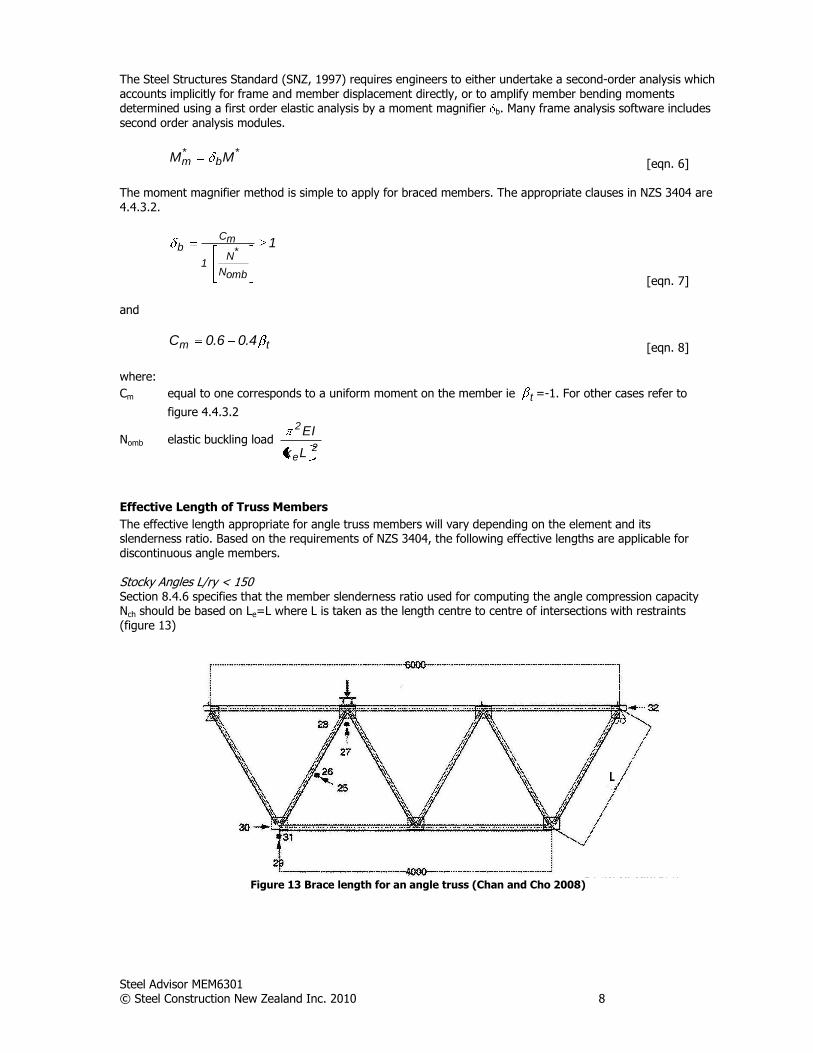
The effective length appropriate for angle truss members will vary depending on the element and its slenderness ratio. Based on the requirements of NZS 3404, the following effective lengths are applicable for discontinuous angle members. Stocky Angles L/ry < 150 Section 8.4.6 specifies that the member slenderness ratio used for computing the angle compression capacity Nch should be based on Le=L where L is taken as the length centre to centre of intersections with restraints (figure 13)
Figure 13 Brace length for an angle truss (Chan and Cho 2008)
Steel Advisor MEM6301 © Steel Construction New Zealand Inc. 2010 9
Slender Angles L/ry 150
The effective length for slender discontinuous angles is a function of the connection configuration and the degree of restraint provided by the connection. Section 6.6.2 presents equations for the effective length of various arrangements of discontinuous angles. These are presented graphically in table 6.6 of NZS 3404. The length L shall be taken as the distance between the intersections of the setting lines of the bolts (figure 13).
Continuous Chords
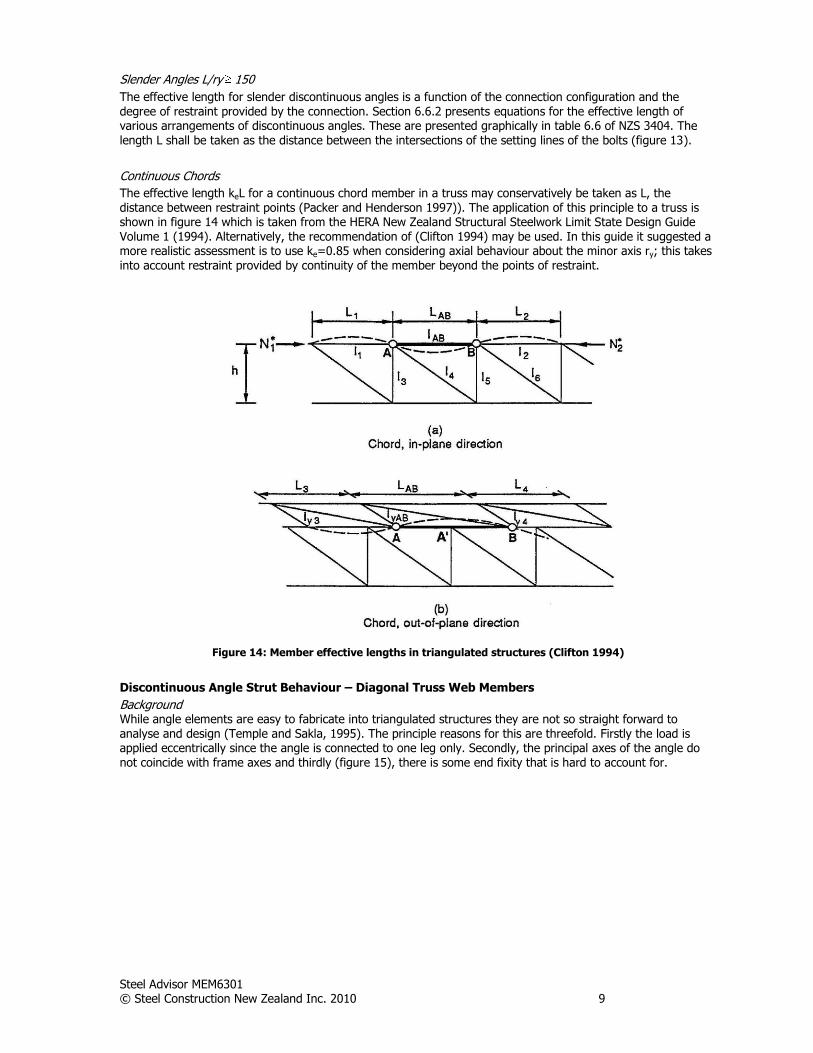
The effective length keL for a continuous chord member in a truss may conservatively be taken as L, the distance between restraint points (Packer and Henderson 1997)). The application of this principle to a truss is shown in figure 14 which is taken from the HERA New Zealand Structural Steelwork Limit State Design Guide Volume 1 (1994). Alternatively, the recommendation of (Clifton 1994) may be used. In this guide it suggested a more realistic assessment is to use ke=0.85 when considering axial behaviour about the minor axis ry; this takes into account restraint provided by continuity of the member beyond the points of restraint.
Figure 14: Member effective lengths in triangulated structures (Clifton 1994)
Discontinuous Angle Strut Behaviour – Diagonal Truss Web Members
Background While angle elements are easy to fabricate into triangulated structures they are not so straight forward to analyse and design (Temple and Sakla, 1995). The principle reasons for this are threefold. Firstly the load is applied eccentrically since the angle is connected to one leg only. Secondly, the principal axes of the angle do not coincide with frame axes and thirdly (figure 15), there is some end fixity that is hard to account for.
Steel Advisor MEM6301 © Steel Construction New Zealand Inc. 2010 10
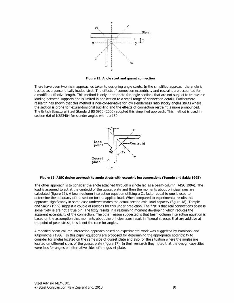
Figure 15: Angle strut and gusset connection
There have been two main approaches taken to designing angle struts. In the simplified approach the angle is treated as a concentrically loaded strut. The effects of connection eccentricity and restraint are accounted for in a modified effective length. This method is only appropriate for angle sections that are not subject to transverse loading between supports and is limited in application to a small range of connection details. Furthermore research has shown that this method is non-conservative for low slenderness ratio stocky angles struts where the section is prone to flexural-torsional buckling and the effects of connection restraint is more pronounced. The British Structural Steel Standard BS 5950 (2000) adopted this simplified approach. This method is used in
section 6.6 of NZS3404 for slender angles with L 150.
Figure 16: AISC design approach to angle struts with eccentric leg connections (Temple and Sakla 1995)
The other approach is to consider the angle attached through a single leg as a beam-column (AISC 1994). The load is assumed to act at the centroid of the gusset plate and then the moments about principal axes are calculated (figure 16). A beam-column interaction equation utilising a Cm factor equal to one is used to
determine the adequacy of the section for the applied load. When compared to experimental results this approach significantly in some case underestimates the actual section axial load capacity (figure 18). Temple and Sakla (1995) suggest a couple of reasons for this under prediction. The first is that real connections possess some fixity ie are not a true pin. The fixity results in a restraining moment developing which reduces the apparent eccentricity of the connection. The other reason suggested is that beam-column interaction equation is based on the assumption that moments about the principal axes result in flexural stresses that are additive at the point of peak stress, this is not the case for angles. A modified beam-column interaction approach based on experimental work was suggested by Woolcock and Kitipornchai (1986). In this paper equations are proposed for determining the appropriate eccentricity to consider for angles located on the same side of gusset plate and also for the situation where the angles are located on different sides of the gusset plate (figure 17). In their research they noted that the design capacities were less for angles on alternative sides of the gusset plate.

Steel Advisor MEM6301 © Steel Construction New Zealand Inc. 2010 11
Figure 17: Joint eccentricities (Woolcock and Kitipornchai, 1986)
The proposed design equation was written in a working stress format. This approach became the basis for the procedure that was adopted by the Australian Limit State Steel Structures Standard (AS4100, 1998) for angle struts connected through one leg. NZS 3404 also includes this approach with some slight modification. This modification will be discussed under point 4 on the following page. By way of comparison, the results of the three different methods, Simplified (British), beam-column (North American and modified beam –column (Australian) are compared against results of angle capacities determined in a computer study undertaken by Trahir et. al. (1969) (figure 18). These results were produced for pin and fixed end conditions. A pin ended connection would be appropriate for an angle connected to a chord with little torsional stiffness such as a tee section. A composite truss top chord regularly connected to a concrete slab would represent a fixed end situation.
Figure 18: Comparison of predicted angle strut design capacities computed using different methods (Temple and Sakla, 1995)
Steel Advisor MEM6301 © Steel Construction New Zealand Inc. 2010 12
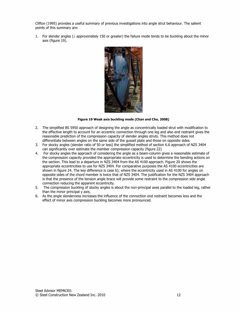
Clifton (1995) provides a useful summary of previous investigations into angle strut behaviour. The salient points of this summary are: 1. For slender angles ( approximately 150 or greater) the failure mode tends to be buckling about the minor
axis (figure 19).
Figure 19 Weak axis buckling mode (Chan and Cho, 2008)
2. The simplified BS 5950 approach of designing the angle as concentrically loaded strut with modification to
the effective length to account for an eccentric connection through one leg and also end restraint gives the reasonable prediction of the compression capacity of slender angles struts. This method does not differentiate between angles on the same side of the gusset plate and those on opposite sides.
3. For stocky angles (slender ratio of 50 or less) the simplified method of section 6.6 approach of NZS 3404 can significantly over estimate the member compression capacity (figure 22)
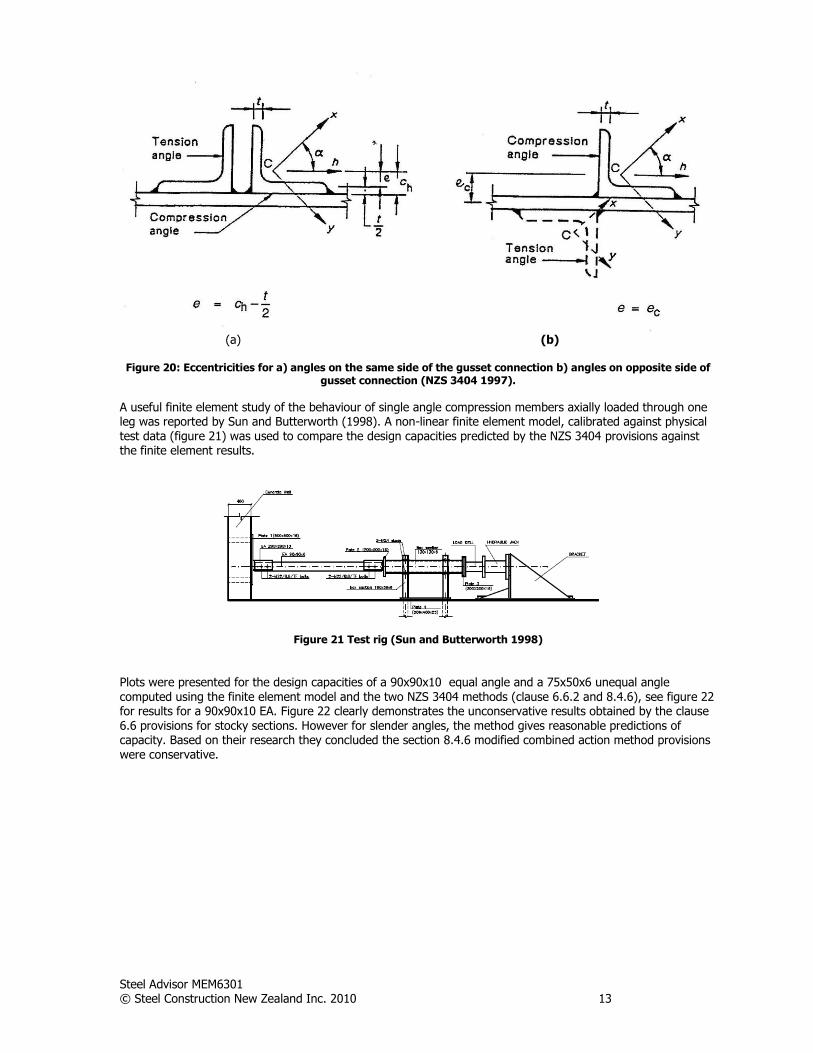
4. For stocky angles the approach of considering the angle as a beam-column gives a reasonable estimate of the compression capacity provided the appropriate eccentricity is used to determine the bending actions on the section. This lead to a departure in NZS 3404 from the AS 4100 approach. Figure 20 shows the appropriate eccentricities to use for NZS 3404. For comparative purposes the AS 4100 eccentricities are shown in figure 24. The key difference is case b); where the eccentricity used in AS 4100 for angles on opposite sides of the chord member is twice that of NZS 3404. The justification for the NZS 3404 approach is that the presence of the tension angle brace will provide some restraint to the compression side angle connection reducing the apparent eccentricity.
5. The compression buckling of stocky angles is about the non-principal axes parallel to the loaded leg, rather than the minor principal y axis.
6. As the angle slenderness increases the influence of the connection end restraint becomes less and the effect of minor axis compression buckling becomes more pronounced.
Steel Advisor MEM6301 © Steel Construction New Zealand Inc. 2010 13
(a) (b)
Figure 20: Eccentricities for a) angles on the same side of the gusset connection b) angles on opposite side of
gusset connection (NZS 3404 1997).
A useful finite element study of the behaviour of single angle compression members axially loaded through one leg was reported by Sun and Butterworth (1998). A non-linear finite element model, calibrated against physical test data (figure 21) was used to compare the design capacities predicted by the NZS 3404 provisions against the finite element results.
Figure 21 Test rig (Sun and Butterworth 1998)
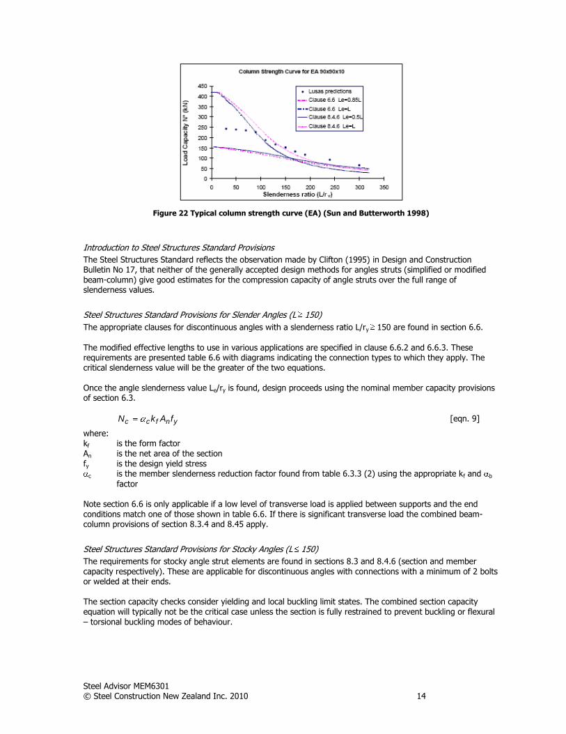
Plots were presented for the design capacities of a 90x90x10 equal angle and a 75x50x6 unequal angle
computed using the finite element model and the two NZS 3404 methods (clause 6.6.2 and 8.4.6), see figure 22 for results for a 90x90x10 EA. Figure 22 clearly demonstrates the unconservative results obtained by the clause 6.6 provisions for stocky sections. However for slender angles, the method gives reasonable predictions of capacity. Based on their research they concluded the section 8.4.6 modified combined action method provisions were conservative.
Steel Advisor MEM6301 © Steel Construction New Zealand Inc. 2010 14
Figure 22 Typical column strength curve (EA) (Sun and Butterworth 1998)
Introduction to Steel Structures Standard Provisions
The Steel Structures Standard reflects the observation made by Clifton (1995) in Design and Construction Bulletin No 17, that neither of the generally accepted design methods for angles struts (simplified or modified beam-column) give good estimates for the compression capacity of angle struts over the full range of slenderness values.
Steel Structures Standard Provisions for Slender Angles (L 150)
The appropriate clauses for discontinuous angles with a slenderness ratio L/ry 150 are found in section 6.6.
The modified effective lengths to use in various applications are specified in clause 6.6.2 and 6.6.3. These requirements are presented table 6.6 with diagrams indicating the connection types to which they apply. The critical slenderness value will be the greater of the two equations. Once the angle slenderness value Le/ry is found, design proceeds using the nominal member capacity provisions of section 6.3.
ynfcc fAkN [eqn. 9]
where: kf is the form factor An is the net area of the section fy is the design yield stress
c is the member slenderness reduction factor found from table 6.3.3 (2) using the appropriate kf and b
factor Note section 6.6 is only applicable if a low level of transverse load is applied between supports and the end conditions match one of those shown in table 6.6. If there is significant transverse load the combined beam-column provisions of section 8.3.4 and 8.45 apply.
Steel Structures Standard Provisions for Stocky Angles (L 150)
The requirements for stocky angle strut elements are found in sections 8.3 and 8.4.6 (section and member capacity respectively). These are applicable for discontinuous angles with connections with a minimum of 2 bolts or welded at their ends. The section capacity checks consider yielding and local buckling limit states. The combined section capacity equation will typically not be the critical case unless the section is fully restrained to prevent buckling or flexural
– torsional buckling modes of behaviour.
Steel Advisor MEM6301 © Steel Construction New Zealand Inc. 2010 15
0.1M
M
M
M
N
N
sy
*y
sx
*x
s
*
[eqn. 10]
The combined member capacity equation considers buckling modes of behaviour.
0.1cosM
M
N
N
bx
*h
ch
*
[eqn. 11]
where: N* is the design axial compression force in the member
*hM is the design bending moment acting about the rectangular h axis parallel to the loaded leg
Nch is the nominal member capacity axial compression, determined in accordance with 6.3, of a single angle compression member with Le=L about the rectangular h axis parallel to the loaded leg
Mbx is the nominal member capacity calculated in accordance with 5.6, for an angle bent about the major axis, using an m factor appropriate to the distribution of design bending moment along the member
is the angle between the x axis and the h axis (see figure 20)
If the end connection to the angle strut consists of single bolt which is quite common for flybrace details, the the recommended in DCB No 17 (Clifton 1995) should be adopted. Equation 11 can be modified for a single end bolt as follows.
8.0cosM
M
N
N
bx
*h
ch
*
[eqn. 12]
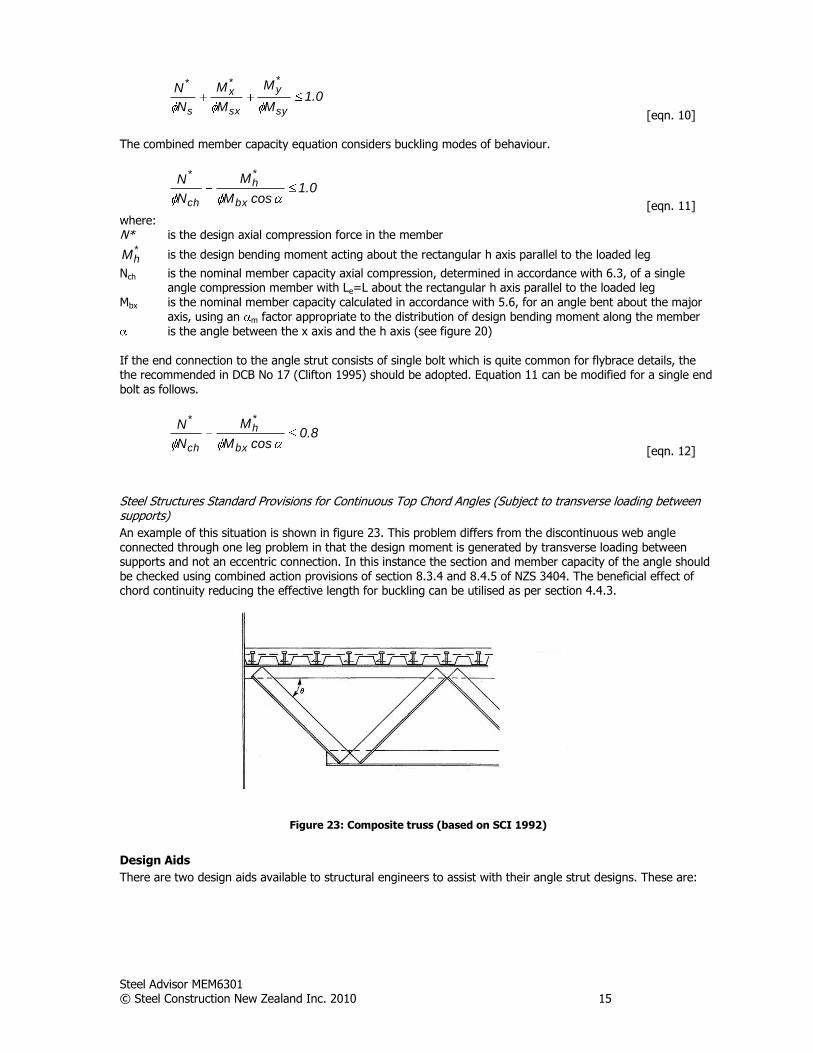
Steel Structures Standard Provisions for Continuous Top Chord Angles (Subject to transverse loading between supports)
An example of this situation is shown in figure 23. This problem differs from the discontinuous web angle connected through one leg problem in that the design moment is generated by transverse loading between supports and not an eccentric connection. In this instance the section and member capacity of the angle should be checked using combined action provisions of section 8.3.4 and 8.4.5 of NZS 3404. The beneficial effect of chord continuity reducing the effective length for buckling can be utilised as per section 4.4.3.
Figure 23: Composite truss (based on SCI 1992)
Design Aids
There are two design aids available to structural engineers to assist with their angle strut designs. These are:
Steel Advisor MEM6301 © Steel Construction New Zealand Inc. 2010 16
Fletcher Easysteel Structural Steel Properties and Design Charts (1997)
The Fletcher Easy Steel publication provides design capacity tables for slender angles utilising the section 6.6 provisions. Care needs to be used with this table as the results presented cover both stocky and slender angles. In accordance with clause 6.6 the simple method should only be used for angles with slenderness ratios of 150 or greater. Furthermore the tables are produced for grade 250 steel. Hot rolled angles are now manufactured in grade 300 steel.
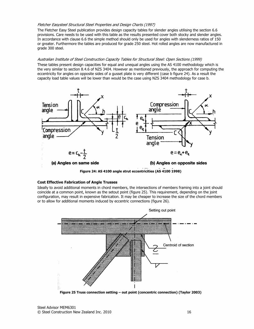
Australian Institute of Steel Construction Capacity Tables for Structural Steel: Open Sections (1999)
These tables present design capacities for equal and unequal angles using the AS 4100 methodology which is the very similar to section 8.4.6 of NZS 3404. However as mentioned previously, the approach for computing the eccentricity for angles on opposite sides of a gusset plate is very different (case b figure 24). As a result the capacity load table values will be lower than would be the case using NZS 3404 methodology for case b.
Figure 24: AS 4100 angle strut eccentricities (AS 4100 1998)
Cost Effective Fabrication of Angle Trusses
Ideally to avoid additional moments in chord members, the intersections of members framing into a joint should coincide at a common point, known as the setout point (figure 25). This requirement, depending on the joint configuration, may result in expensive fabrication. It may be cheaper to increase the size of the chord members or to allow for additional moments induced by eccentric connections (figure 26).
Figure 25 Truss connection setting – out point (concentric connection) (Taylor 2003)
Steel Advisor MEM6301 © Steel Construction New Zealand Inc. 2010 17
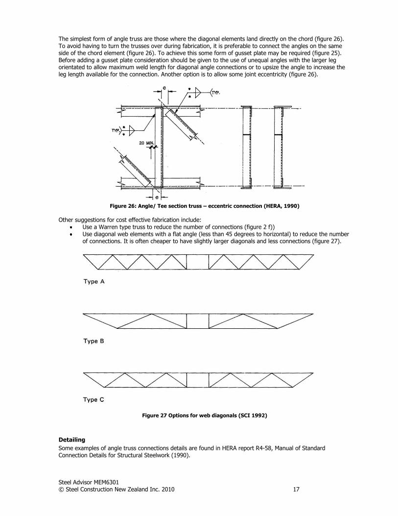
The simplest form of angle truss are those where the diagonal elements land directly on the chord (figure 26). To avoid having to turn the trusses over during fabrication, it is preferable to connect the angles on the same side of the chord element (figure 26). To achieve this some form of gusset plate may be required (figure 25). Before adding a gusset plate consideration should be given to the use of unequal angles with the larger leg orientated to allow maximum weld length for diagonal angle connections or to upsize the angle to increase the leg length available for the connection. Another option is to allow some joint eccentricity (figure 26).
Figure 26: Angle/ Tee section truss – eccentric connection (HERA, 1990)
Other suggestions for cost effective fabrication include:
Use a Warren type truss to reduce the number of connections (figure 2 f)) Use diagonal web elements with a flat angle (less than 45 degrees to horizontal) to reduce the number
of connections. It is often cheaper to have slightly larger diagonals and less connections (figure 27).
Figure 27 Options for web diagonals (SCI 1992)
Detailing
Some examples of angle truss connections details are found in HERA report R4-58, Manual of Standard Connection Details for Structural Steelwork (1990).
Steel Advisor MEM6301 © Steel Construction New Zealand Inc. 2010 18
References Beer, F.P. and Johnston, E.,R, Mechanics of Materials, McGraw Hill International Book Company, Japan, 1981 BSI, Structural Use of Steelwork in Buildings – Part 1: Code of Practice for Design – Rolled and welded sections, BS 5950. London, BSI, 2000 Chan, S. L. and Cho, S.H., Second Order analysis and Design of Angle Trusses Part 1: Elastic Analysis and Design, Science Direct, Engineering Structures 30, pp 615-625, 2008 Clifton, G. C., New Zealand Structural Steelwork Limit State Design Guide Volume 1, HERA Report R4-80, NZ Heavy Engineering Research Association, Manukau City, 1994 Clifton, G. C., Design and Construction Bulletin No 17, NZ Heavy Engineering Research Association, Manukau City, 1995
Clifton, G. C., Notes Prepared for a Seminar Prepared on the Steel Structures Standard 1997, HERA Report R4-101, NZ Heavy Engineering Research Association, Manukau City, 1999 Fletcher Easy Steel, Structural Steel Properties and Design Charts, July, 1997 HERA, Manual of Standard Connection Details for Structural Steelwork, Report R4-58, NZ Heavy Engineering Research Association, Manukau City, 1990 Packer, J.A. and Henderson, J.E., Hollow Structural Section Connections and Trusses, Canadian Institute of Steel Construction, Ontario, Canada, 1997 SA, Steel Structures Standard, AS 4100, Standards Australia, Sydney, 1998 SCI, Design Guide for Continuous Composite Bridges: 1 Compact Sections, SCI –P-065, Steel Construction Institute, Silkwood Park, 1989 SCI, Design of Composite Trusses, SCI –P-083, Steel Construction Institute, Silkwood Park, 1992 SCI, Steel Designers Manual, Blackwell Science Ltd, Oxford, 2003 SNZ, Steel Structures Standard (incorporating amendments 1 and 2), NZS 3404:1997, Standards New Zealand, Wellington, 2007 Sun, J. and Butterworth, J.W., Behaviour of Single Angle Compression Members Axially Loaded Through One Leg, Australasian Structural Engineering Conference, 1998 Syam, A. (editor), Design and Capacity Tables for Structural Steel – Volume 1 Open Sections, Australian
Institute Steel Construction, Sydney, 1999 Taylor., J.T., An Engineer’s Guide to Fabricating Steel Structures, Volume 2: Successful Welding of Steel Structures, Australian Steel Institute, Sydney, 2003 Temple, M.C., and Sakla, S.S., Considerations of the Design of Compression Members Attached by One Leg, Proceedings of the International Conference on Structural Stability and Design, Sydney, 1995 Trahir, N.S., Usami, T., and Galambos, T.V., Eccentrically loaded single angle columns. Research report No 11, Civil and Environmental Engineering Department, Washington University, St Louis, 1969 Woolcock, S.T., and Kitipornchai, S., Design of single angle web struts in trusses, Journal of Structural Engineering, Vol. 112, No 6, pp 1327-1345