MEM09209A - acru.com.au · Specifying Surface Roughness Value:..... 26 Surface Lay Pattern: ........
170
MEM09209A 2013 Detail bearings, seals and other componentry in mechanical drawings.
Transcript of MEM09209A - acru.com.au · Specifying Surface Roughness Value:..... 26 Surface Lay Pattern: ........

MEM09209A - Detail bearings, seals and other componentry in mechanical drawings.
BlackLine Design Page 1 of 170
26th January 2013 – Version 1
MEM09209B
MEM09209A
2013
Detail bearings, seals and other componentry in mechanical drawings.

MEM09209A - Detail bearings, seals and other componentry in mechanical drawings.
BlackLine Design Page 2 of 170
26th January 2013 – Version 1
First Published January 2013
This work is copyright. Any inquiries about the use of this material should
be directed to the publisher.
Edition 1 – January 2013

MEM09209A - Detail bearings, seals and other componentry in mechanical drawings.
BlackLine Design Page 3 of 170
26th January 2013 – Version 1
Conditions of Use:
Unit Resource Manual
Manufacturing Skills Australia Courses
This Student’s Manual has been developed by BlackLine Design for use in the
Manufacturing Skills Australia Courses.
All rights reserved. No part of this publication may be printed or transmitted in any
form by any means without the explicit permission of the writer.
Statutory copyright restrictions apply to this material in digitally and hard copy.
Copyright BlackLine Design 2013

MEM09209A - Detail bearings, seals and other componentry in mechanical drawings.
BlackLine Design Page 4 of 170
26th January 2013 – Version 1
Feedback:
Your feedback is essential for improving the quality of these manuals.
Please advise the appropriate industry specialist of any changes, additions, deletions or
anything else you believe would improve the quality of this Student Workbook. Don’t
assume that someone else will do it. Your comments can be made by photocopying the
relevant pages and including your comments or suggestions.
Forward your comments to:
BlackLine Design
Sydney, NSW, 2000

MEM09209A - Detail bearings, seals and other componentry in mechanical drawings.
BlackLine Design Page 5 of 170
26th January 2013 – Version 1
Aims of the Competency Unit
This unit covers producing drawings to Australian Standard 1100 or equivalent where the
critical dimensions and associated tolerances for components and/or materials are
selected from supplier/manufacturers' catalogues using design specifications.
Manual drafting or drawing equipment is used or where a CAD (Computer Aided Design)
system is used, Unit MEM09009C (Create 2D drawings using computer aided design
system) and/or Unit MEM09010C (Create 3D models using computer aided design
system) should also be considered
Unit Hours 72 Hours
Prerequisites: MEM09002B Interpret technical drawing
MEM09003B Prepare basic engineering drawing

MEM09209A - Detail bearings, seals and other componentry in mechanical drawings.
BlackLine Design Page 6 of 170
26th January 2013 – Version 1
Elements and Performance Criteria 1. Prepare assembly,
layout and detail
drafting
1.1
Drawings are prepared in plane orthogonal, isometric
projection or equivalent including auxiliary views and
sections to Australian Standard 1100.
1.2
Layout, assembly and component drawings are
prepared from specification.
1.3
Drawings are dimensioned and labelled using supplied
tolerances in accordance with Australian Standard
1100.
1.4
Drawings are produced to specification in accordance
with standard operating procedures.
1.5
Standard symbols to Australian Standard 1100 or
equivalent are used to specify requirements.
2. Determine
component and/or
material
requirement
2.1 Components and/or materials are selected from
supplier/manufacturers’ catalogues using design
specifications
Required Skills and Knowledge Required skills include:
preparing drawings using appropriate projections and views in accordance with
AS1100 or equivalent, see above note in the range statement
producing layout, assembly and component drawings in conformance with
specification
inserting all relevant dimensions, tolerances and instructions in the drawing
producing drawings to specification
appropriately using standard symbols in accordance with AS1100 or equivalent in
the drawings produced
obtaining component specifications in accordance with work place procedures
reading, interpreting and following information written job instructions,
specifications, standard operating procedures, charts, lists, drawings and other
applicable reference documents
planning and sequencing operations
checking and clarifying task related information
checking for conformance to specifications
undertaking numerical operations, geometry and calculations/formulae within the
scope of this unit
Required knowledge includes:
appropriate projection for the drawing purpose
reasons for selecting the chosen projection
reasons for including auxiliary views in drawings
requirements of AS1100 or equivalent with respect to dimensions, tolerances and
labels
procedures for producing component, layout and/or assembly drawings
drawing specifications
common symbols used in drawings to AS1100 or equivalent
design specifications of the component
appropriate components and materials from supplier/manufacturers' catalogues
reasons for selecting the chosen components and/or materials
safe work practices and procedures
MEM09209A - Detail bearings, seals and other componentry in mechanical drawings.
BlackLine Design Page 7 of 170
26th January 2013 – Version 1
Free Software Download Sites The follow site allows their software to be downloaded, installed and used free of charge.
AutoCAD
www.students.autodesk.com
To download the AutoCAD or any other Autodesk software free of charge, you
have to register as a student. Click on Register and complete your details on
the following screens using your TAFE email address which is shown on your
TAFE receipt when paying your fees; you may need to enquire at your TAFE
Library or Administration Centre for your password.
Once registered, you can start to download any of 30 programs. Download the
version you will be using in class to avoid the problems of opening and saving
your drawings as versions.
On downloading the program, make a note of the Product Key and Serial
Number which are required to register the software.
The software is licensed for 13 months for educational purposes ONLY. At the
end of the licence period the software will not operate however the latest version
can then be downloaded and installed on the same, or a new computer.
MEM09209A - Detail bearings, seals and other componentry in mechanical drawings.
BlackLine Design Page 8 of 170
26th January 2013 – Version 1
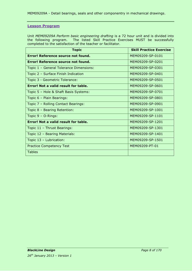
Lesson Program
Unit MEM09209A Perform basic engineering drafting is a 72 hour unit and is divided into
the following program. The listed Skill Practice Exercises MUST be successfully
completed to the satisfaction of the teacher or facilitator.
Topic Skill Practice Exercise
Error! Reference source not found. MEM09209-SP-0101
Error! Reference source not found. MEM09209-SP-0201
Topic 1 – General Tolerance Dimensions: MEM09209-SP-0301
Topic 2 – Surface Finish Indication MEM09209-SP-0401
Topic 3 - Geometric Tolerance: MEM09209-SP-0501
Error! Not a valid result for table. MEM09209-SP-0601
Topic 5 – Hole & Shaft Basis Systems: MEM09209-SP-0701
Topic 6 – Plain Bearings: MEM09209-SP-0801
Topic 7 – Rolling Contact Bearings: MEM09209-SP-0901
Topic 8 – Bearing Retention: MEM09209-SP-1001
Topic 9 – O-Rings: MEM09209-SP-1101
Error! Not a valid result for table. MEM09209-SP-1201
Topic 11 – Thrust Bearings: MEM09209-SP-1301
Topic 12 – Bearing Materials: MEM09209-SP-1401
Topic 13 – Lubrication: MEM09209-SP-1501
Practice Competency Test MEM09209-PT-01
Tables

MEM09209A - Detail bearings, seals and other componentry in mechanical drawings.
BlackLine Design Page 9 of 170
26th January 2013 – Version 1
Contents: Conditions of Use:............................................................................................... 3
Unit Resource Manual ....................................................................................... 3 Manufacturing Skills Australia Courses ................................................................ 3
Feedback: .......................................................................................................... 4 Aims of the Competency Unit ............................................................................... 5 Unit Hours ......................................................................................................... 5 Prerequisites: ..................................................................................................... 5 Elements and Performance Criteria ....................................................................... 6 Required Skills and Knowledge ............................................................................. 6 Free Software Download Sites .............................................................................. 7 Lesson Program .................................................................................................. 8 Contents: .......................................................................................................... 9
Topic 1 – General Tolerance Dimensions: ......................................................... 13 Required Skills: ................................................................................................ 13 Required Knowledge: ........................................................................................ 13 Lesson Aim: ..................................................................................................... 13 Tolerance Dimensioning: ................................................................................... 13 Methods of Expressing Tolerance: ....................................................................... 14
Unilateral Tolerance: ....................................................................................... 14 Bilateral Tolerance: ......................................................................................... 14 Limit of Size: ................................................................................................. 14 AutoCAD Terminology: .................................................................................... 14 Fundamentals for Tolerance Selection ............................................................... 15 Tolerance for Linear Dimensions: ...................................................................... 15 Tolerance for Angular Dimensions: ................................................................... 16 Tolerance for Holes and Shafts: ........................................................................ 16 Number of Decimal Points: .............................................................................. 17
Convert Unilateral and Bilateral Tolerances to Limit of Size Tolerances: ................... 17 Datum Dimensioning: ........................................................................................ 17
Datum Edges/Surfaces: ................................................................................... 18 Review Questions: MEM09209-RQ-01 ............................................................. 19 Skill Practice Exercises: ................................................................................... 21
Topic 2 – Surface Finish Indication ................................................................... 24 Required Skills: ................................................................................................ 24 Required Knowledge: ........................................................................................ 24 Surface Finish: ................................................................................................. 24 Finished Surface Symbols: ................................................................................. 24
Machining Mandatory: ..................................................................................... 24 Machining Optional: ........................................................................................ 24 Machining Not Permitted: ................................................................................ 24
Proportions of Surface Symbols: ......................................................................... 25 Surface Roughness: .......................................................................................... 25
Specifying Surface Roughness Value: ................................................................ 26 Surface Lay Pattern: ....................................................................................... 26 Material Removal Allowance: ........................................................................... 26 Symbol for Special Requirements: .................................................................... 26
Location of Surface Finish Symbols on Drawings: .................................................. 27 Review Questions: MEM09209-RQ-02 ............................................................. 28 Skill Practice Exercises: ................................................................................... 29
Topic 3 - Geometric Tolerance: ......................................................................... 31 Required Skills: ................................................................................................ 31 Required Knowledge: ........................................................................................ 31
Definition: ..................................................................................................... 31 Geometric Tolerancing: ..................................................................................... 31 Symbols for Tolerance of Position and Form: ........................................................ 32 Basic Dimensional Symbol: ................................................................................ 33 Datum Identifying Symbol: ................................................................................ 33

MEM09209A - Detail bearings, seals and other componentry in mechanical drawings.
BlackLine Design Page 10 of 170
26th January 2013 – Version 1
Supplementary Symbols: ................................................................................ 33 Combined Symbols: ........................................................................................ 33
Explanation of Characteristic Symbols: ................................................................ 34 Straightness Tolerance: ................................................................................... 34 Flatness Tolerance: ......................................................................................... 34 Roundness (Circularity) Tolerance: ................................................................... 34 Cylindricity Tolerance: ..................................................................................... 35 Profile of a Line Tolerance: .............................................................................. 35 Profile of a Surface Tolerance:.......................................................................... 35 Angularity Tolerance: ...................................................................................... 35 Parallelism Tolerance: ..................................................................................... 36 Perpendicularity Tolerance: .............................................................................. 36 Concentricity Tolerance: .................................................................................. 36
Placing the Symbols Using AutoCAD: ................................................................... 37 Review Questions: MEM09209-RQ-03 ........................................................... 38 Skill Practice Exercises .................................................................................... 41
Topic 4 – Keys, Keyways & Keyseats: ............................................................... 43 Required Skills: ................................................................................................ 43 Required Knowledge: ........................................................................................ 43 Keys & Keyways: .............................................................................................. 43
Rectangular Key ............................................................................................. 43 Gib Head ....................................................................................................... 43 Woodruff Key ................................................................................................. 43 Pratt and Whitney Key (Feather Key) ................................................................ 43 Round Key ..................................................................................................... 44 Saddle Key .................................................................................................... 44
Dimensions and Tolerances for Keyways: ............................................................. 44 Types of Fit: ..................................................................................................... 45
Free .............................................................................................................. 45 Normal .......................................................................................................... 45 Close ............................................................................................................ 45 Interference ................................................................................................... 45
Selecting the Key Size: ...................................................................................... 45 Selecting Shaft and Hub Dimensions and Tolerances: ............................................ 46
Shaft and Hub Widths ..................................................................................... 46 Shaft and Hub Depths ..................................................................................... 47 Select the Keyway Corner Radius: .................................................................... 49 Review Questions: MEM09209-RQ-04 ........................................................... 50 Skill Practice Exercises .................................................................................... 52
Topic 5 – Hole & Shaft Basis Systems: .............................................................. 55 Required Skills: ................................................................................................ 55 Required Knowledge: ........................................................................................ 55 Hole Basis System: ........................................................................................... 55 Shaft Basis System: .......................................................................................... 56 Classification of Fits: ......................................................................................... 57
Review Questions: MEM09209-RQ-05 ........................................................... 60 Skill Practice Exercises .................................................................................... 61
Topic 6 – Plain Bearings: .................................................................................. 63 Required Skills: ................................................................................................ 63 Required Knowledge: ........................................................................................ 63 Bearings: ......................................................................................................... 63 Classification of Bearings: .................................................................................. 63 Sliding Contact Bearings: ................................................................................... 63
Plain Journal or Sleeve Bearings: ...................................................................... 63 Pedestal Bearing: ........................................................................................... 64 Footstep Thrust Bearing: ................................................................................. 65 Plain Thrust Bearing: ...................................................................................... 65 Skill Practice Exercises .................................................................................... 66

MEM09209A - Detail bearings, seals and other componentry in mechanical drawings.
BlackLine Design Page 11 of 170
26th January 2013 – Version 1
Topic 7 – Rolling Contact Bearings: .................................................................. 68 Required Skills: ................................................................................................ 68 Required Knowledge: ........................................................................................ 68 Rolling Contact Bearings: ................................................................................... 68 Ball Bearings: ................................................................................................... 68
Single Row Deep Groove Ball Bearings .............................................................. 68 Double Row Deep Groove Ball Bearings: ............................................................ 69 Self-aligning Bearing: ..................................................................................... 69 Angular Contact Bearing: ................................................................................ 70
Determining Bearing Sizes: ................................................................................ 70 Skill Practice Exercise: .................................................................................... 72
Topic 8 – Bearing Retention: ............................................................................ 74 Required Skills: ................................................................................................ 74 Required Knowledge: ........................................................................................ 74 Retention of Bearings: ....................................................................................... 74 Bearing Retaining Cap (Outer Ring Clamping)....................................................... 75 Circlips: ........................................................................................................... 76
Display of Circlips on an Assembly Drawing: ...................................................... 77 Circlip Grooves: ................................................................................................ 78
Skill Practice Exercises: ................................................................................... 80
Topic 9 – O-Rings: ............................................................................................ 82 Required Skills: ................................................................................................ 82 Required Knowledge: ........................................................................................ 82 Seals: O-Rings: ................................................................................................ 82
Static Seals: .................................................................................................. 82 Dynamic Seals: .............................................................................................. 84
Other Cross Sectional Options: ........................................................................... 86 Lobed Seals (X-rings)...................................................................................... 86 Square Rings ................................................................................................. 86 U-Cups .......................................................................................................... 86 T-seals .......................................................................................................... 87 Crown Seals ................................................................................................... 87 Skill Practice Exercises .................................................................................... 88
Topic 10 – Seals: .............................................................................................. 90 Required Skills: ................................................................................................ 90 Required Knowledge: ........................................................................................ 90 Seals: ............................................................................................................. 90 Types of Seals: ................................................................................................. 90 Seal Materials: ................................................................................................. 95
Skill Practice Exercises .................................................................................... 96
Topic 11 – Thrust Bearings: .............................................................................. 98 Required Skills: ................................................................................................ 98 Required Knowledge: ........................................................................................ 98 Thrust Bearings: ............................................................................................... 98
Ball Thrust Bearings: ...................................................................................... 98 Needle Roller Thrust Bearings Thrust Bearing ....................................................101 Angular Contact Thrust Bearing .......................................................................102 Fluid Thrust Bearing: .....................................................................................102 Review Questions: MEM09209-RQ-06 ............................................................103 Skill Practice Exercises: ..................................................................................104
Topic 12 – Bearing Materials: ......................................................................... 106 Required Skills: ............................................................................................... 106 Required Knowledge: ....................................................................................... 106 Plain Bearing Materials ..................................................................................... 106 Metal Bearings ................................................................................................. 106 Non-metal Bearings ......................................................................................... 108
Skill Practice Exercises ...................................................................................110

MEM09209A - Detail bearings, seals and other componentry in mechanical drawings.
BlackLine Design Page 12 of 170
26th January 2013 – Version 1
Topic 13 – Lubrication: ................................................................................... 112 Required Skills: ............................................................................................... 112 Required Knowledge: ....................................................................................... 112 Purpose for Lubricating Engineering Components: ................................................ 112 Methods of Lubrication: .................................................................................... 113 Wet Lubrication Materials: ................................................................................ 115 Dry Lubricating Materials: ................................................................................. 116
Review Questions MEM09209-RQ-07: ............................................................117 Skill Practice Exercises ...................................................................................118
Practice Competency Test ............................................................................... 120
Tables ............................................................................................................. 121 Table 1 – Internal Circlips ................................................................................. 121 Table 2 – External Circlips ................................................................................. 124 Table 3 – Deep Groove Ball Bearings .................................................................. 127 Table 4 – Self Aligning Ball Bearings ................................................................... 129 Table 5 - Angular Contact Ball Bearing................................................................ 131 Table 6 - Cylindrical Roller Bearings ................................................................... 133 Table 7 - Needle Roller Bearings ........................................................................ 135 Table 8 – Thrust Ball Bearings ........................................................................... 137 Table 9 – Taper Roller Bearings ......................................................................... 138 Table 10 – Taper Roller Bearings: Abutment and Fillets ........................................ 140 Table 11 – Wiper Seals ..................................................................................... 142 Table 12 – Rod Seals ........................................................................................ 144 Table 13 – Piston Ring ...................................................................................... 146 Table 14 – Guide or Wear Ring .......................................................................... 148 Table 15 – Vee Packing Seals ............................................................................ 150 Table 16 – O-Rings .......................................................................................... 154 Table 17 - Hole Basis System ............................................................................ 156 Table 18 – Shaft Basis System .......................................................................... 159 Table 19 – Typical Surface Roughness Height Application ...................................... 162 Table 20 – Lay Symbols .................................................................................... 164 Table 21 – Dimensions and Tolerances for Keyways ............................................. 165
MEM09209A - Detail bearings, seals and other componentry in mechanical drawings.
Topic 1 - General Toleranced Dimensions
BlackLine Design Page 13 of 170
26th January 2013 – Version 1
Topic 1 – General Tolerance Dimensions:
Required Skills: Add dimensions containing tolerances to a detail drawing.
Convert Unilateral and Bilateral to Limit of Size.
Required Knowledge:
Dimensioning techniques to AS1100.
Basic calculations (addition and subtraction)
Lesson Aim: The aim of this lesson is to develop the skill of the draftsperson in applying tolerance
dimensions to a detail drawing using the tolerances as supplied by the engineer. Specific
lessons on the selection and application of tolerances and determining tolerances from
charts and tables will be covered in later Topics in this unit.
Tolerance Dimensioning: Unfortunately, it is impossible to make anything to the exact size as there are always
small amounts of variation due to wear of cutting tools, misalignment, or many other
reasons. Components can be made very close, even to a few millionths of a millimetre
but accuracy is expensive. Exact sizes are not needed, only varying degrees of accuracy
according to the functional requirements; a workshop reconditioning engines for motor
vehicles would soon be bankrupt if they attempted to make every engine with formula
racing car engine accuracy. The engines will be acceptable IF they are made with
reasonable differences in the sizes of the engine components. The problem can easily
be overcome if a tolerance is applied on each dimension.
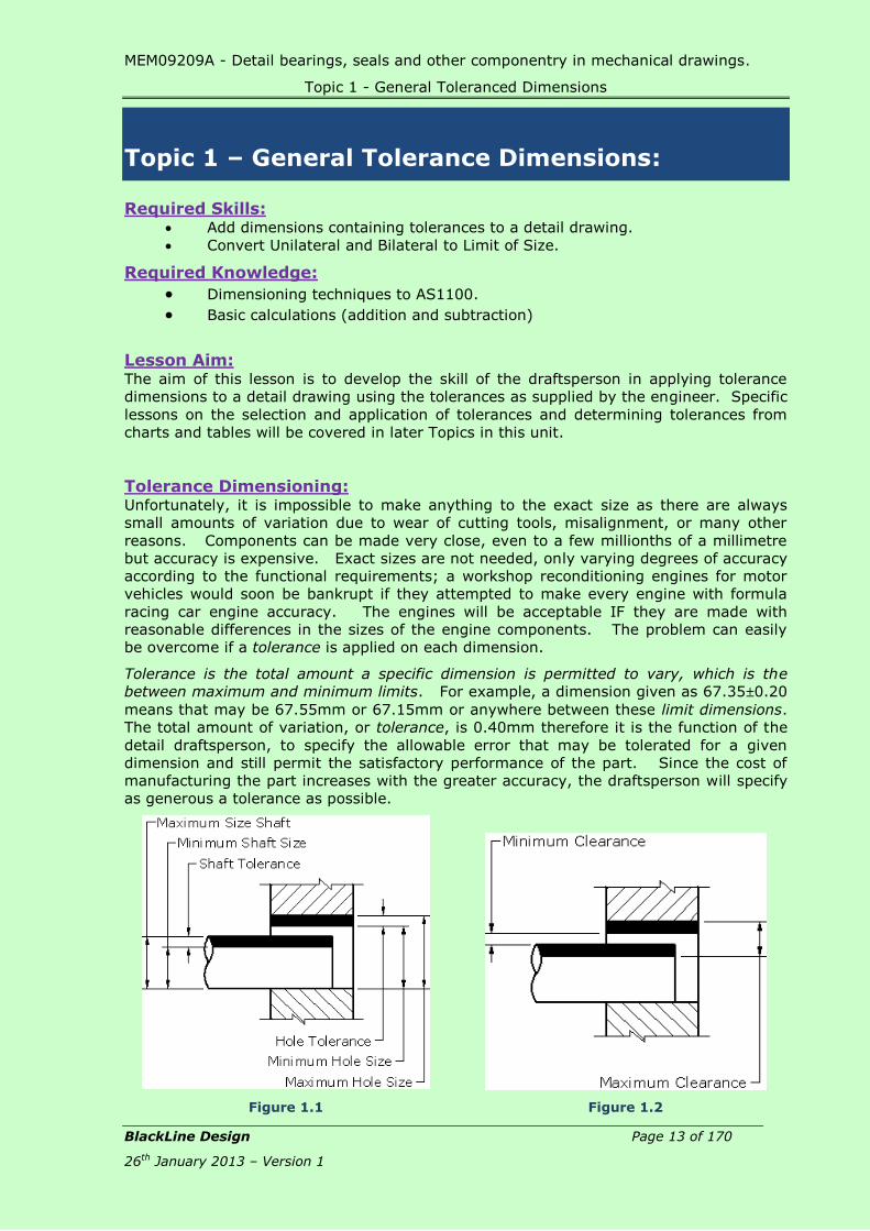
Tolerance is the total amount a specific dimension is permitted to vary, which is the
between maximum and minimum limits. For example, a dimension given as 67.350.20
means that may be 67.55mm or 67.15mm or anywhere between these limit dimensions.
The total amount of variation, or tolerance, is 0.40mm therefore it is the function of the
detail draftsperson, to specify the allowable error that may be tolerated for a given
dimension and still permit the satisfactory performance of the part. Since the cost of
manufacturing the part increases with the greater accuracy, the draftsperson will specify
as generous a tolerance as possible.
Figure 1.1
Figure 1.2

MEM09209A - Detail bearings, seals and other componentry in mechanical drawings.
Topic 1 - General Toleranced Dimensions
BlackLine Design Page 14 of 170
26th January 2013 – Version 1
Methods of Expressing Tolerance: There are three methods used to specify tolerance on engineering drawings:
Unilateral
Bilateral
Limit of Size or Direct
Unilateral Tolerance:
A unilateral tolerance is one where the total allowable variation is given in ONE direction.
The dimension consists of a basic size with a tolerance that is either slightly smaller, or
larger. Figure 1.3 shows the nominal size as 50 with the tolerance of 0.5 being applied
slightly to make the diameter larger; Figure 1.4 shows the tolerance of 0.5 being applied
to make the diameter smaller.
Figure 1.5 and Figure 1.6 have two tolerance values for each dimension however the
tolerances are in the one direction, either larger by 0.2 to 0.5 or smaller by 0.1 to 0.5.
Figure 1.3
Figure 1.4
Figure 1.5
Figure 1.6
Bilateral Tolerance:
A bilateral tolerance is one where the total allowable variation is given in TWO directions.
The dimension is given as a basic size with a small variation in size that can be either
larger or smaller. Bilateral tolerances should generally be equal, but special design
considerations may sometimes dictate unequal values.
Figure 1.7
Figure 1.8
Figure 1.7 shows the nominal size as 50 with a tolerance both larger and smaller by
0.05; in Figure 1.8 the same nominal size of 50 is required but the diameter can be
larger by 0.04 or smaller by 0.06. Both toleranced dimensions are Bilateral.
Limit of Size:
Limit of size specifies the maximum and permissible sizes that the
part can be manufactured.
Limit of Size toleranced dimensions are always placed in the centre of
the dimension line with the upper value (maximum size) located
above the dimension line and the lower value (minimum size) placed
below the dimension line; Unilateral and Bilateral dimensions are
always placed above the dimension line. In all cases, the number of
decimal places in the tolerance and the preferred size must be the
same.
AutoCAD Terminology:
AutoCAD uses the terminology “Limits” for Limits of Size, “Deviation” and “Symmetrical”,
and are applied to a selected Dimension Style.
Limit of Size
or Direct

MEM09209A - Detail bearings, seals and other componentry in mechanical drawings.
Topic 1 - General Toleranced Dimensions
BlackLine Design Page 15 of 170
26th January 2013 – Version 1
The Limit style sets up the tolerance to display the upper and lower sizes.
The upper limit is placed above the dimension line while the lower limit is
placed below the dimension line.
A rule for toleranced dimensions requires the number of decimal points in the
nominal size and tolerances to be the same; eg. 1, 2, 3 or 4 decimal points.
Toleranced dimensions can be added to a detail drawing produced using AutoCAD using 2
methods:
Creating a new dimension style (eg. Tolerance); once the dimension has been
applied to the view, the upper and lower limits can be modified accordingly.
Creating several new dimension styles (eg. Tol-1, Tol-2, Tol-3); the
toleranced dimension is applied to the view using the correct dimension style.
The disadvantage is there could be many dimension styles required.
Fundamentals for Tolerance Selection
Before the engineer can decide on the precision necessary for a particular part and
specify the proper fits and tolerances, an understanding on the manufacturing process
and the use of the component is required. Many factors such as the length of the
engagement, bearing load, speed, lubrication, temperature, humidity and materials must
be taken into consideration when selecting the tolerances. In many cases, practical
experience is necessary in determining the fit conditions guaranteeing proper
performance.
Before being able to select appropriate tolerances, it is essential to know the precision
attainable with various machine tools and manufacturing methods; e.g. drilled holes
must not have a tolerance applied which is smaller than can be achieved with a drill.
Tolerance for Linear Dimensions:
Toleranced dimensions are applied to a drawing using the same rules as for nominal
dimensions with the exception that Limit of Size tolerances MUST be centred each side of
the dimension line with the upper (or maximum) tolerance on top of the line and the
lower (or minimum tolerance below the dimension line. In the case of Unilateral and
Bilateral tolerance dimensions, the nominal size followed by the tolerance is placed above
the dimension line.
It is recommended that the aligned method of dimensioning is utilized when placing
toleranced dimensions on a drawing as several vertical dimensions require less room and
the text does not run into one continuous string.
The preferred method for placing toleranced dimensions is shown in Figure 1.9 where the
dimensions are aligned with the feature. Figure 1.10 has the dimensions spaced identical
to Figure 1.9 bus as can be seen, the dimension text always horizontal and shown, the
text from one dimension overlaps the neighbouring text and cannot be read. The
resulting
Figure 1.11 is easily read but the spacing between the dimension line has been increased
which could result in insufficient room on a tight-fitting drawing. Figure 1.12 has the
dimension lines spaced at the correct distance and the text in each toleranced dimension
moved vertically up or down to allow the dimensions to be read with more clarity;
moving a vast number of dimension text could lead to excessive drawing time increasing
the cost of the drawing.

MEM09209A - Detail bearings, seals and other componentry in mechanical drawings.
Topic 1 - General Toleranced Dimensions
BlackLine Design Page 16 of 170
26th January 2013 – Version 1
Figure 1.9 Figure 1.10
Figure 1.11 Figure 1.12
The length required to indicate the dimensions and view of Figure 1.9 measures 150
while Figure 1.11 measures 160 and Figure 1.12 measures 130.
Tolerance for Angular Dimensions:
The tolerance on angular dimensions is normally given as bilateral and shown as
74±0.5°. If the tolerance is given in minutes the toleranced dimension is shown as
74±0°15’. If the tolerance is given in seconds it is shown as 74±0’30”.
Tolerance for Holes and Shafts:
Holes are dimensioned in accordance with AS1100 where the dimension can be placed on
a dimension line through the hole/shaft or placed as a leader line with the text
horizontal. The leader must touch the edge and point to the centre of the hole/shaft.
The diameter symbol appears before the hole/shaft size followed by the dimension text.

MEM09209A - Detail bearings, seals and other componentry in mechanical drawings.
Topic 1 - General Toleranced Dimensions
BlackLine Design Page 17 of 170
26th January 2013 – Version 1
Number of Decimal Points:
In Unilateral and bilateral tolerance dimensions, the number of decimal points showing in
the nominal size and the tolerance must be the same. In Limit of Size tolerances, the
upper and lower values must have the same number of decimal points.
Where the values are calculated with the last decimal place being zero (0) for both the
upper and lower values, the zeros can be removed.
Correct Wrong
Convert Unilateral and Bilateral Tolerances to Limit of Size Tolerances: To convert Unilateral and Bilateral Tolerances to Limits of Size, simply add or subtract
the given tolerance to the basic size to obtain the maximum and minimum limits.
When adding tolerances too, or subtracting from the nominal dimension, the number of
decimal points should be the same to reduce the errors made during mental calculations.
Example:
Convert 45.64
+0.14
-0.23 to a Limit of Size
Upper limit = 45.64 + 0.14
Lower limit = 45.64 – 0.25
= 45.78
= 45.41
Example:
Convert 62.25
+0
-0.015 to a Limit of Size
Upper limit = 63.25 + 0
Lower limit = 63.250 – 0.014
= 63.25
= 63.236
Datum Dimensioning: Datum dimensions consist of dimensions given from the same lines, centres, points or
edges of the surfaces of a part. The leading CAD software packages use the Baseline
dimension to create a datum dimension. Most datum dimensioning is given as
horizontal and vertical dimensions placed about the extreme left and bottom edges of the
part however they can also be hole or feature centrelines or any other notable feature.
Datum dimensioning reduces the error resulting from the accumulation of errors.

MEM09209A - Detail bearings, seals and other componentry in mechanical drawings.
Topic 1 - General Toleranced Dimensions
BlackLine Design Page 18 of 170
26th January 2013 – Version 1
Figure 1.13
Figure 1.14
In the images above Figure 1.13 use the bottom and left edges for the datum while
Figure 1.14 uses the major vertical and horizontal centrelines for the datum.
All dimensions must be spaced at a uniform distance when baseline dimensioning is used
on a drawing.
Datum Edges/Surfaces:
Datum edges and surfaces are identified by a solid filled
triangle and a designating letter (A, B, C …) centred
inside a square bounding box with a line linking the box
to the triangle.
The height of the Datum letter is the same height as
used throughout the drawing. The height of the Datum
box is twice the text height.
Figure 1.15

MEM09209A - Detail bearings, seals and other componentry in mechanical drawings.
Topic 1 - General Toleranced Dimensions
BlackLine Design Page 19 of 170
26th January 2013 – Version 1
Review Questions: MEM09209-RQ-01
Answers are at the rear of the reference book.
1. Define the term “Tolerance”.
___________________________________________________________________
___________________________________________________________________
2. Name 3 methods of displaying tolerances on drawings giving examples of each
method.
a) ______________________________________________________________
b) ______________________________________________________________
c) ______________________________________________________________
3. Convert the following Unilateral and Bilateral tolerances to Limit of Size.
+0.06 __________________________
35.26
-0.00 __________________________
+0.00 __________________________
56.93
-0.05 __________________________
+0.16 __________________________
92.91
-0.005 __________________________
+0.07 __________________________
15.20
-0.01 __________________________
+0.120 __________________________
86.26
+0.115 __________________________
+0.105 __________________________
147.25
+0.032 __________________________
4. If a hole has a maximum diameter of 59.125mm and a minimum diameter of
58.975mm, what is the tolerance?

MEM09209A - Detail bearings, seals and other componentry in mechanical drawings.
Topic 1 - General Toleranced Dimensions
BlackLine Design Page 20 of 170
26th January 2013 – Version 1
_________________________________________________________________
5. Define the following terminology as applied to tolerancing.
a) Bilateral Tolerance
_______________________________________________________________
_______________________________________________________________
b) Limit of Size
_______________________________________________________________
______________________________________________________________
c) Nominal Size
______________________________________________________________
______________________________________________________________
d) Basic Dimension
______________________________________________________________
______________________________________________________________
e) Allowance
______________________________________________________________
______________________________________________________________
6. Name the preferred method of tolerancing.
_____________________________________________________________
7. With the limit of size method of tolerancing, the larger limit is written above the line.
(Tick one Box Only).
TRUE FALSE

MEM09209A - Detail bearings, seals and other componentry in mechanical drawings.
Topic 1 - General Toleranced Dimensions
BlackLine Design Page 21 of 170
26th January 2013 – Version 1
Skill Practice Exercises:
Skill Practice Exercise MEM09209-SP-0301.
Create a new drawing using the template provided on the network drive called
Crankshaft and complete the drawing by adding all dimensions, border and a Title Block.
All toleranced dimensions indicated are to be converted and displayed as “Limit of Size”
dimensions using the tolerances shown in the following table. Plot the final drawing onto
an A3 sheet at an appropriate scale. Save the file as MEM09209-SP-0301.
Dimension Maximum Minimum
Ø75 -0.25 -0.105
46.5 +0.09 +0.025
25 +0 -0.05
25 -0.005 -0.012
166.5 +0.25 -0.05
41 +0.15 -0.15

MEM09209A - Detail bearings, seals and other componentry in mechanical drawings.
Topic 1 - General Toleranced Dimensions
BlackLine Design Page 22 of 170
26th January 2013 – Version 1
Skill Practice Exercise MEM09209-SP-0302.
Create a new drawing using the template provided on the network drive called Flap Link
and complete the drawing by adding all dimensions, border and a Title Block. All
toleranced dimensions shown in the Figure below are to be displayed as “Limit of Size”
toleranced dimensions. Plot the final drawing onto an A3 sheet at an appropriate scale.
Save the file as MEM09209-SP-0302.
Skill Practice Exercise MEM09209-SP-0303.
Create a new drawing using the template provided on the network drive called Rocker
Arm and complete the drawing by adding all dimensions, border and a Title Block. In
creating the details drawings All toleranced dimensions are to be displayed as “Limit of
Size”. Plot the final drawing onto an A3 sheet at an appropriate scale. Save the file as
MEM09209-SP-0303.

MEM09209A - Detail bearings, seals and other componentry in mechanical drawings.
Topic 1 - General Toleranced Dimensions
BlackLine Design Page 23 of 170
26th January 2013 – Version 1
Skill Practice Exercise MEM09209-SP-0304.
Create a new drawing using the template provided on the network drive called Hook
Bearing and complete the drawing by adding all dimensions, missing features, border
and a Title Block. All toleranced dimensions shown in the Figure below are to be
displayed as “Limit of Size” toleranced dimensions. Plot the final drawing onto an A3
sheet at an appropriate scale. Save the file as MEM09209-SP-0304.
Dimen
sion
Tolerance
A ±0.05
B ±0.125
C ±0.025
D +0.035
-0
E +0
-0.078
F +0.08
+0.03
G Drill Ø12.5±.05
Counterbore Ø17x12 deep
MEM09209A - Detail bearings, seals and other componentry in mechanical drawings.
Topic 2 - Surface Finish Indication
BlackLine Design Page 24 of 170
26th January 2013 – Version 1
Topic 2 – Surface Finish Indication
Required Skills:
Place surface finish symbols on a detail drawing.
Place geometric tolerance symbols on a detail drawing.
Required Knowledge:
Surface roughness.
Geometric tolerances.
Surface Finish: Modern development of high-speed machines has resulted in higher loadings and
increased speeds of moving parts. To withstand these more severe operating conditions
with minimum friction and wear, a particular surface finish is often essential, making it
necessary for the designer and detailer to accurately describe the required finish to the
trades actively involved in manufacturing the part/s.
All surface finish control starts in the drawing office. The detailer has the responsibility
of specifying the correct surface to give the maximum performance and service life at the
lowest cost. In selecting the required surface finish for any particular part, the
designers base decisions on past experience with similar parts, on field service data, or
on engineering tests. Factors such as size and function of the parts, type of loading,
speed and direction of movement, operating conditions, physical characteristics of both
materials on contact, type and amount of lubricant, contaminants, temperature influence
the choice of the surface finish.
The two principal reasons for specifying surface finish are to:
Reduce friction.
Control wear.
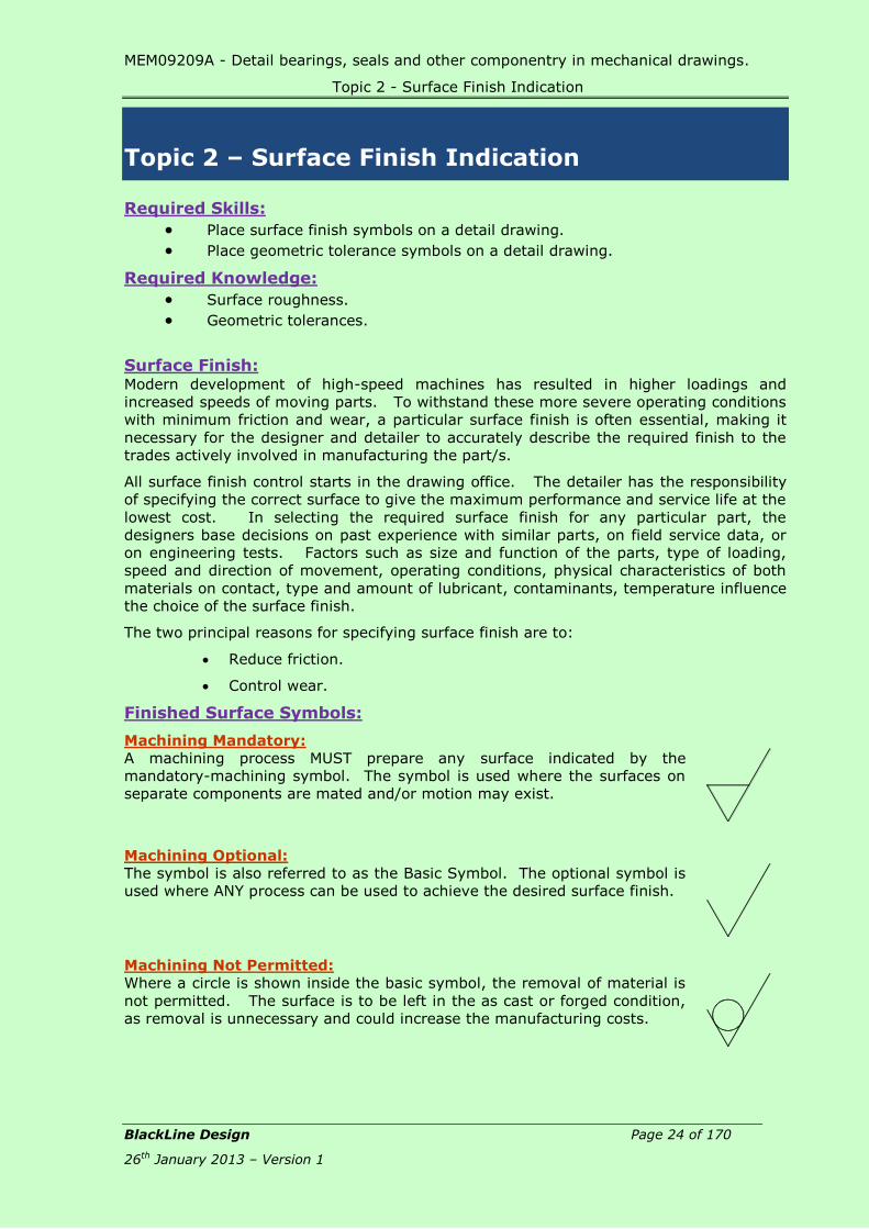
Finished Surface Symbols:
Machining Mandatory:
A machining process MUST prepare any surface indicated by the
mandatory-machining symbol. The symbol is used where the surfaces on
separate components are mated and/or motion may exist.
Machining Optional:
The symbol is also referred to as the Basic Symbol. The optional symbol is
used where ANY process can be used to achieve the desired surface finish.
Machining Not Permitted:
Where a circle is shown inside the basic symbol, the removal of material is
not permitted. The surface is to be left in the as cast or forged condition,
as removal is unnecessary and could increase the manufacturing costs.

MEM09209A - Detail bearings, seals and other componentry in mechanical drawings.
Topic 2 - Surface Indication
BlackLine Design Page 25 of 170
26th January 2013 – Version 1
Proportions of Surface Symbols: The proportions of the size of the Surface Symbols are
given as a direct size of the lettering used to indicate
the roughness values as shown in Error! Reference
ource not found.. The angled lines are drawn at 60º
in both directions with the height of the short leg being
1.4 x the height of the lettering and the longer leg
being 2.8 x the lettering height.
Figure 2.1
Example:
If the lettering height used on the drawing is 3.5mm; the length of each leg would be
1.4mm x 3.5mm. The sizes would be rounded of and drawn at 5mm and 10mm.
Surface Roughness: The proper functioning and wear life of a part frequently depends upon the smoothness
quality of its surfaces. Any surface, despite its apparent smoothness, has minute peaks
and valleys, the height of which is termed “surface roughness” and which may or may
not be superimposed on a more general “waviness”. The most prominent direction of
tool marks is called the “lay”
Figure 2.2 shows a magnified view of the profile of a surface where ALL smooth surfaces
consist of peaks and valleys. The roughness (or smoothness) of a surface is given by a
measurement called the Roughness Value (Ra) which is the average height of the hills
measured from the centre of the profile.
Figure 2.2
The sampling length is the distance over which the surface roughness is measured.
The roughness value can be specified on the surface finish symbol using one of two
methods:
Specifying the roughness height in micrometers – 0.025m to 50m,
Specifying a roughness grade number – N1 to N12

MEM09209A - Detail bearings, seals and other componentry in mechanical drawings.
Topic 2 - Surface Indication
BlackLine Design Page 26 of 170
26th January 2013 – Version 1
Specifying Surface Roughness Value:
The Surface Roughness can be specified as a maximum value, or as a tolerance using
maximum and minimum values as shown in Figure 2.3.
Maximum Surface Roughness
Only Specified
Maximum and Minimum Surface
Roughness Specified
Figure 2.3
Surface Lay Pattern:
The term “lay” refers to the pattern that tool marks leave on the surface of a component
and is the direction of the predominant surface pattern produced by those tool marks or
grains of the surface ordinarily determined by the production method used. Sometimes
it is necessary to specify the lay in a conjunction with special surface finish requirements.
Material Removal Allowance:
When it is desirable to indicate the amount of material to be removed, the amount of
material in millimetres is shown to the left of the symbol. Methods of indicating material
removal allowance are shown in Figure 2.4.
Means
Figure 2.4
Symbol for Special Requirements:
The symbols shown in Figure 2.3 are usually sufficient to specify the surface finish,
however, in some circumstances; more comprehensive details need to be specified as
indicated in Figure 2.5.
A = Roughness Value
B = Production Method
e.g., Turn, Grind, Ream
C = Sample Length
D = Lay
E = Machining Allowance
Figure 2.5

MEM09209A - Detail bearings, seals and other componentry in mechanical drawings.
Topic 2 - Surface Indication
BlackLine Design Page 27 of 170
26th January 2013 – Version 1
Location of Surface Finish Symbols on Drawings: Surface finish symbols are placed so that they can be read from the bottom or right side
of the drawing. To achieve the correct method, the symbol may be applied to leader
lines and projection lines that extend from the surfaces on the bottom or right side of the
view. Figure 2.6 shows the correct methods for applying the general machining symbols
to a drawing while Figure 2.7 shows the incorrect method.
Figure 2.6
Figure 2.7

MEM09209A - Detail bearings, seals and other componentry in mechanical drawings.
Topic 2 - Surface Indication
BlackLine Design Page 28 of 170
26th January 2013 – Version 1
Review Questions: MEM09209-RQ-02
1. Sketch and name the 3 basic Surface Finish Symbols.
_______________ _______________ _______________
2. Name two reasons for specifying surface finish on engineering detail drawings.
a) ___________________________________________________________
___________________________________________________________
b) ____________________________________________________________
____________________________________________________________
3. Provide a short description of surface roughness.
____________________________________________________________
____________________________________________________________
____________________________________________________________
4. Complete the following drawings by adding the surface finish symbols specifying
the amount of allowable surface roughness to machine the top surfaces.
Surface roughness is
to be a maximum of 3.2 roughness of 1.6 and a
Indicate a maximum surface
roughness using an appropriate
Show an average surface
Roughness Value numberminimum of 0.8
MEM09209A - Detail bearings, seals and other componentry in mechanical drawings.
Topic 2 - Surface Indication
BlackLine Design Page 29 of 170
26th January 2013 – Version 1
Skill Practice Exercises:
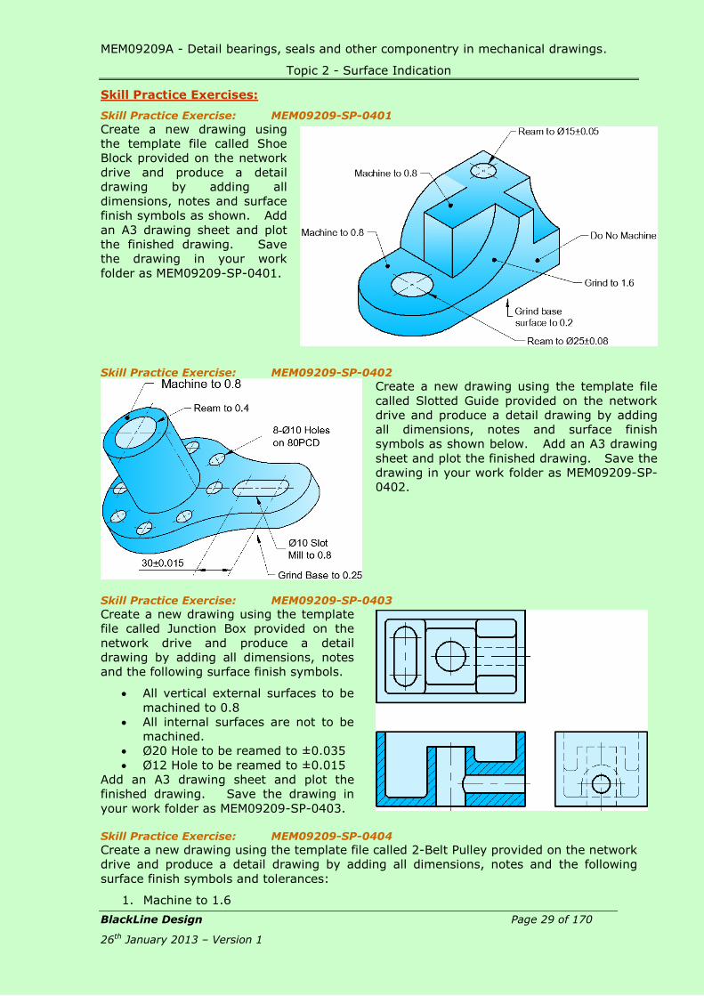
Skill Practice Exercise: MEM09209-SP-0401
Create a new drawing using
the template file called Shoe
Block provided on the network
drive and produce a detail
drawing by adding all
dimensions, notes and surface
finish symbols as shown. Add
an A3 drawing sheet and plot
the finished drawing. Save
the drawing in your work
folder as MEM09209-SP-0401.
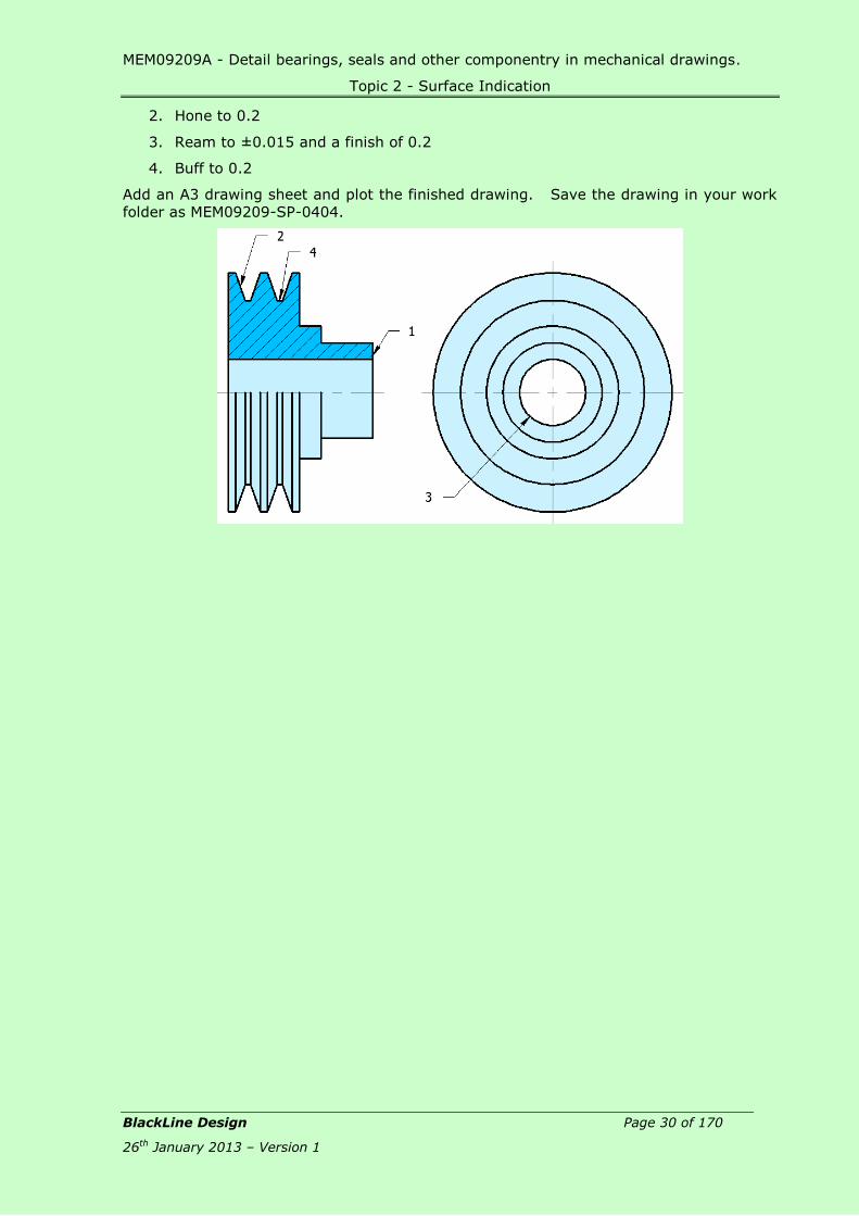
Skill Practice Exercise: MEM09209-SP-0402
Create a new drawing using the template file
called Slotted Guide provided on the network
drive and produce a detail drawing by adding
all dimensions, notes and surface finish
symbols as shown below. Add an A3 drawing
sheet and plot the finished drawing. Save the
drawing in your work folder as MEM09209-SP-
0402.
Skill Practice Exercise: MEM09209-SP-0403
Create a new drawing using the template
file called Junction Box provided on the
network drive and produce a detail
drawing by adding all dimensions, notes
and the following surface finish symbols.
All vertical external surfaces to be
machined to 0.8
All internal surfaces are not to be
machined.
Ø20 Hole to be reamed to ±0.035
Ø12 Hole to be reamed to ±0.015
Add an A3 drawing sheet and plot the
finished drawing. Save the drawing in
your work folder as MEM09209-SP-0403.
Skill Practice Exercise: MEM09209-SP-0404
Create a new drawing using the template file called 2-Belt Pulley provided on the network
drive and produce a detail drawing by adding all dimensions, notes and the following
surface finish symbols and tolerances:
1. Machine to 1.6
MEM09209A - Detail bearings, seals and other componentry in mechanical drawings.
Topic 2 - Surface Indication
BlackLine Design Page 30 of 170
26th January 2013 – Version 1
2. Hone to 0.2
3. Ream to ±0.015 and a finish of 0.2
4. Buff to 0.2
Add an A3 drawing sheet and plot the finished drawing. Save the drawing in your work
folder as MEM09209-SP-0404.

MEM09209A - Detail bearings, seals and other componentry in mechanical drawings.
Topic 4 – Keys, Keyways & Keyseats
BlackLine Design Page 31 of 170
26th January 2013 – Version 1
Topic 3 - Geometric Tolerance:
Required Skills:
Place geometric tolerance symbols on a detail drawing in accordance with
Engineer’s specifications.
Produce a detail drawing of engineering components indicating Geometric
Tolerance where applicable
Required Knowledge:
Definition of “Geometric Tolerance”.
Geometric tolerances.
Dimensioning techniques
Definition:
Geometric Tolerances states the maximum allowable variations of a form or its position
from the perfect geometry implied on the drawing.
Geometric Tolerancing: The term “geometric” refers to various forms as a plane, cylinder, cone, square,
hexagon, etc. Theoretically, these are perfect forms, but, because it is impossible to
produce perfect forms, it may be necessary to specify the amount of variation permitted.
These tolerances specify either the diameter or the width of a tolerance zone within
which a surface or the axis of a cylinder or hole must be if the part is to meet the
required accuracy for proper function and fit. When tolerances of form are not given on
a drawing, it is customary to assume that, regardless of form variations, the part will fit
and function satisfactorily.
Tolerances of form and position or location control such as straightness, parallelism,
perpendicularity or squareness, flatness, concentricity, roundness, angular displacement,
etc. Methods for indicating geometric tolerances by means of geometric characteristic
symbols are as recommended by AS1100 Part 210. Geometric tolerances should not be
added to drawings unless they are specifically required as they may add significantly and
unnecessarily to the cost of manufacture.

MEM09209A - Detail bearings, seals and other componentry in mechanical drawings.
Topic 3 - Geometric Tolerance
BlackLine Design Page 32 of 170
26th January 2013 – Version 1
Symbols for Tolerance of Position and Form: The symbols indicated in Error! Reference source not found. have been adopted by
he Australian Standards for inclusion on drawings. The symbols provide an accurate and
concise means of specifying geometric characteristics and tolerances in a minimum of
space and save the necessity of including long and confusing notes.
Characteristic Symbol
Straightness Individual Flatness
Features Roundness; Circularity
Cylindricity
Form Tolerances Individual
or
Profile of a Line
Related
Features
Profile of a Surface
Angularity
Perpendicularity
(Squareness) Parallelism
Related Position
Location Tolerances Features Concentricity
Symmetry
Runout Tolerances Circular
Total
Supplementary Symbols
MMC Maximum Material Condition
RFS Regardless of Feature Size
DIA Diameter
Figure 3.1
M
S

MEM09209A - Detail bearings, seals and other componentry in mechanical drawings.
Topic 3 - Geometric Tolerance
BlackLine Design Page 33 of 170
26th January 2013 – Version 1
Basic Dimensional Symbol: The basic dimension is defined by the enclosing frame symbol, Figure 3.2. The basic
dimension (size) is the value used to describe the theoretically exact size, shape, or
location of a feature. It is the basis from which permissible variations are established by
tolerances on other dimensions.
Figure 3.2
Datum Identifying Symbol: The datum identifying symbol consists of frame containing a reference letter preceded
and can be placed directly on a centreline, visible outline or projection line, or above a
solid filled triangle as shown in Figure 3.3. A point, line plane, cylinder, or other
geometric form assumed to be exact for purposes of computation may serve as a datum
from which the location or geometric relationship of features of a part may be
established.
Figure 3.3
Supplementary Symbols:
The symbols for the MMC (the minimum hole diameter or the maximum shaft diameter)
and the RFS (the tolerance applies to any of the feature within its size tolerance and/or
the actual size of a datum feature) are indicated in Figure 3.4. The abbreviations MMC
and RFS can be used in notes. The diameter symbol is used instead of the abbreviation
DIA and precedes the specified tolerance in a feature control symbol Figure 3.5.
DIA Diameter
MMC Maximum Material Condition
RFS Regardless of Feature Size
Figure 3.4
Combined Symbols:
Individual symbols, reference letters, required tolerances; etc. may be combined in a
single frame Figure 3.5. A position or form tolerance is given by a feature control symbol
made up of a frame about the appropriate geometric symbol plus the allowable tolerance
with a vertical line separating the symbol and tolerance. Where needed, the tolerance
should be preceded by the symbol for diameter and followed by the symbol for MMC or
RFS. A tolerance of position or form related to a datum is so indicated in the feature
control symbol by placing the datum reference letter following either the geometric
characteristic symbol or the tolerance. Vertical lines separate the entries, and, where
applicable, the datum reference letter entry includes the symbol for MMC or RFS.
Figure 3.5
M
S

MEM09209A - Detail bearings, seals and other componentry in mechanical drawings.
Topic 3 - Geometric Tolerance
BlackLine Design Page 34 of 170
26th January 2013 – Version 1
Explanation of Characteristic Symbols:
Straightness Tolerance:
A straightness tolerance specifies a tolerance zone within which as axis or all points of
the considered element must lie. Straightness is a condition where an element of a
surface or an axis is a straight line.z
E
Figure 3.6
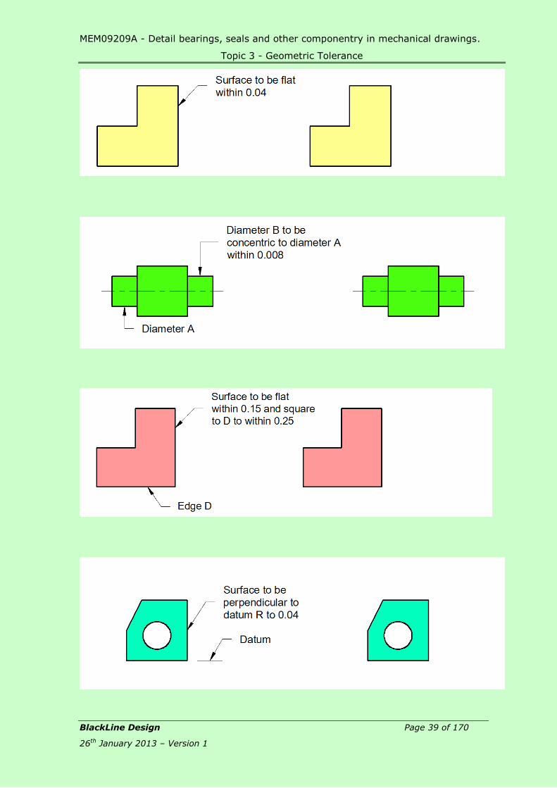
Flatness Tolerance:
A flatness tolerance specifies a tolerance zone defined by two parallel planes within which
the surface must lie. Flatness is the condition of a surface having all elements in one
plane.
Figure 3.7
Roundness (Circularity) Tolerance:
A roundness tolerance specifies a tolerance zone bounded by two concentric circles within
each circular element of the surface must lie. Roundness is a condition of a surface of
revolution where, for a cone or cylinder, all points of the surface intersected by any plane
perpendicular to a common axis are equidistant from that axis. For a sphere, all points
of the surface intersected by any plane passing through a common centre are equidistant
from that centre.
Figure 3.8

MEM09209A - Detail bearings, seals and other componentry in mechanical drawings.
Topic 3 - Geometric Tolerance
BlackLine Design Page 35 of 170
26th January 2013 – Version 1
Cylindricity Tolerance:
Cylindricity is the condition of the surface that forms a cylinder where the surface
elements in cross sections parallel to the axis are straight and parallel and in cross
sections, perpendicular to the axis are parallel.
Figure 3.9
Profile of a Line Tolerance:
A profile of a line tolerance may be directed to a line of any length or shape. With
profile of a line tolerance, datums may be used in some circumstances but would not be
used when the only requirement is the profile shape.
Figure 3.10
Profile of a Surface Tolerance:
The profile of a surface tolerance indicates a tolerance zone having the same
basic surface, with a uniform width equal to the specified tolerance within which
the entire surface must lie.
Figure 3.11
Angularity Tolerance:
An angularity tolerance specifies a tolerance zone defined by two parallel planes at the
specified basic angle (other than 90°) from a datum plane or axis within which the
surface or the axis of the feature must lie.
Figure 3.12
MEM09209A - Detail bearings, seals and other componentry in mechanical drawings.
Topic 3 - Geometric Tolerance
BlackLine Design Page 36 of 170
26th January 2013 – Version 1
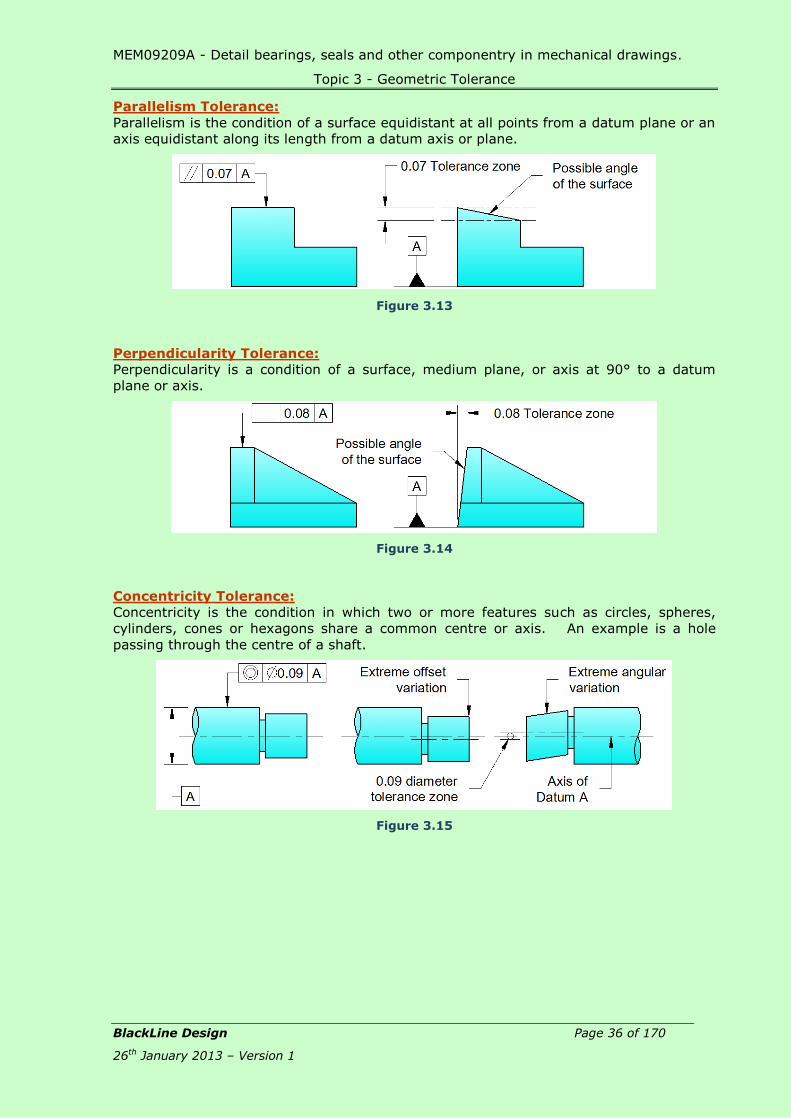
Parallelism Tolerance:
Parallelism is the condition of a surface equidistant at all points from a datum plane or an
axis equidistant along its length from a datum axis or plane.
Figure 3.13
Perpendicularity Tolerance:
Perpendicularity is a condition of a surface, medium plane, or axis at 90° to a datum
plane or axis.
Figure 3.14
Concentricity Tolerance:
Concentricity is the condition in which two or more features such as circles, spheres,
cylinders, cones or hexagons share a common centre or axis. An example is a hole
passing through the centre of a shaft.
Figure 3.15
MEM09209A - Detail bearings, seals and other componentry in mechanical drawings.
Topic 3 - Geometric Tolerance
BlackLine Design Page 37 of 170
26th January 2013 – Version 1
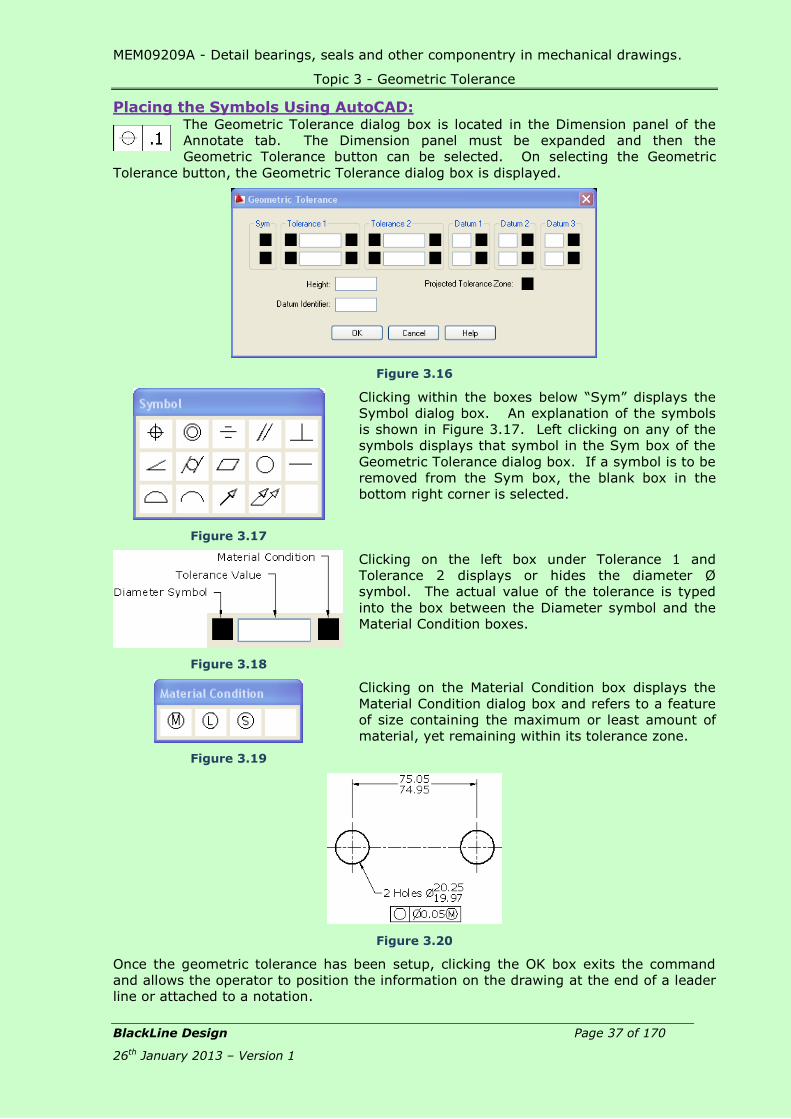
Placing the Symbols Using AutoCAD: The Geometric Tolerance dialog box is located in the Dimension panel of the
Annotate tab. The Dimension panel must be expanded and then the
Geometric Tolerance button can be selected. On selecting the Geometric
Tolerance button, the Geometric Tolerance dialog box is displayed.
Figure 3.16
Figure 3.17
Clicking within the boxes below “Sym” displays the
Symbol dialog box. An explanation of the symbols
is shown in Figure 3.17. Left clicking on any of the
symbols displays that symbol in the Sym box of the
Geometric Tolerance dialog box. If a symbol is to be
removed from the Sym box, the blank box in the
bottom right corner is selected.
Figure 3.18
Clicking on the left box under Tolerance 1 and
Tolerance 2 displays or hides the diameter Ø
symbol. The actual value of the tolerance is typed
into the box between the Diameter symbol and the
Material Condition boxes.
Figure 3.19
Clicking on the Material Condition box displays the
Material Condition dialog box and refers to a feature
of size containing the maximum or least amount of
material, yet remaining within its tolerance zone.
Figure 3.20
Once the geometric tolerance has been setup, clicking the OK box exits the command
and allows the operator to position the information on the drawing at the end of a leader
line or attached to a notation.

MEM09209A - Detail bearings, seals and other componentry in mechanical drawings.
Topic 3 - Geometric Tolerance
BlackLine Design Page 38 of 170
26th January 2013 – Version 1
Review Questions: MEM09209-RQ-03
1. In less than 3 lines, describe the term “Geometric Tolerancing”.
_________________________________________________________________
_________________________________________________________________
_________________________________________________________________
2. Complete the following table by adding the missing information:
Straightness
c
Roundness; Circularity
g
Profile of a Line
d
Angularity
b
Parallelism f
r
Circular
Maximum Material Condition
Regardless of Feature Size
Diameter
3. Note the required geometric tolerance on the blank images provided.
MEM09209A - Detail bearings, seals and other componentry in mechanical drawings.
Topic 3 - Geometric Tolerance
BlackLine Design Page 39 of 170
26th January 2013 – Version 1

MEM09209A - Detail bearings, seals and other componentry in mechanical drawings.
Topic 3 - Geometric Tolerance
BlackLine Design Page 40 of 170
26th January 2013 – Version 1

MEM09209A - Detail bearings, seals and other componentry in mechanical drawings.
Topic 3 - Geometric Tolerance
BlackLine Design Page 41 of 170
26th January 2013 – Version 1
Skill Practice Exercises
Skill Practice Exercise MEM09209-SP-0301
Open drawing MEM09209-SP-0301 and add the surface finish and geometric tolerances
symbols in accordance with the following notes.
A Grind the surface to a
roughness of 0.4; the shaft is
to be round to within 0.04 and
concentric to each other.
B Machine the surface to a
roughness of 1.6, a flatness of
0.5 and perpendicular to the
datum to within 0.01.
C Grind the surface to a
roughness of 0.4; the shaft is
to be round to within 0.04 and
parallel to the datum to 0.025.
D Datum
Save the drawing in your work area as MEM09209-SP-0301.
Skill Practice Exercise MEM09209-SP-0302
Open drawing MEM09209-SP-0302 and add the surface finish and geometric tolerances
symbols in accordance with the following notes.
A Hone the datum surface to a
roughness of 0.2, a flatness of
0.1 and perpendicular to the
datum to 0.08.
B Hone surface to a roughness of
0.2, a flatness of 0.1 and
parallel to surface A to within
0.5.
C Ream the holes to a roughness
of 0.1 and perpendicular to
surface A to 0.04.
D Hone surface to a roughness of
0.2.
Save the drawing in your work area as MEM09209-SP-0302.

MEM09209A - Detail bearings, seals and other componentry in mechanical drawings.
Topic 3 - Geometric Tolerance
BlackLine Design Page 42 of 170
26th January 2013 – Version 1
Skill Practice Exercise MEM09209-SP-0303
Open drawing MEM09209-SP-0303 and add the surface finish and geometric tolerances
symbols in accordance with the following notes.
A Datum surface is machined to
a roughness 0.2 and
straightness of 0.05.
B Bore hole B to a roughness of
0.4, circular and perpendicular
to datum A to 0.2.
C Surface to be a roughness of
1.6 and a flatness of 0.8.
D Datum surface is machined to
a roughness 0.2 and
straightness of 0.1.
E Surface to be machined to a
roughness of 3.2 and parallel
to datum D.
F Ream hole to 0.4 and
perpendicular to datum D to
0.05.
Save the drawing in your work area as MEM09209-SP-0303.
Skill Practice Exercise MEM09209-SP-0304
Open drawing MEM09209-SP-0304 and add the surface finish and geometric tolerances
symbols in accordance with the following notes.
A Surface is not to be machined.
B Hole B to be reamed to
roughness of 0.8 and circular
to 0.2.
C Surface to be a roughness of
1.6 and a flatness of 0.8.
D Surfaces to be a roughness of
0.1 and perpendicular to the
datum TO 0.2.
E Surface to be a roughness of
3.2 and perpendicular to within
0.15 of surface C.
F Datum
Save the drawing in your work area as MEM09209-SP-0304.

MEM09209A - Detail bearings, seals and other componentry in mechanical drawings.
Topic 4 – Keys, Keyways & Keyseats
BlackLine Design Page 43 of 170
26th January 2013 – Version 1
Topic 4 – Keys, Keyways & Keyseats:
Required Skills: Use standard tables to select a key size to suit a specified shaft.
Use standard tables to determine the shaft and hub tolerances dimensions for
square and rectangular keys.
Produce a detail drawing of engineering components containing keyed shaft
and hubs and apply toleranced dimensions for the key.
Required Knowledge: The difference between a “Key”, “Keyseat” and “Keyway”.
Name the various types of key used in engineering applications.
List the types of fit used for keys and keyways.
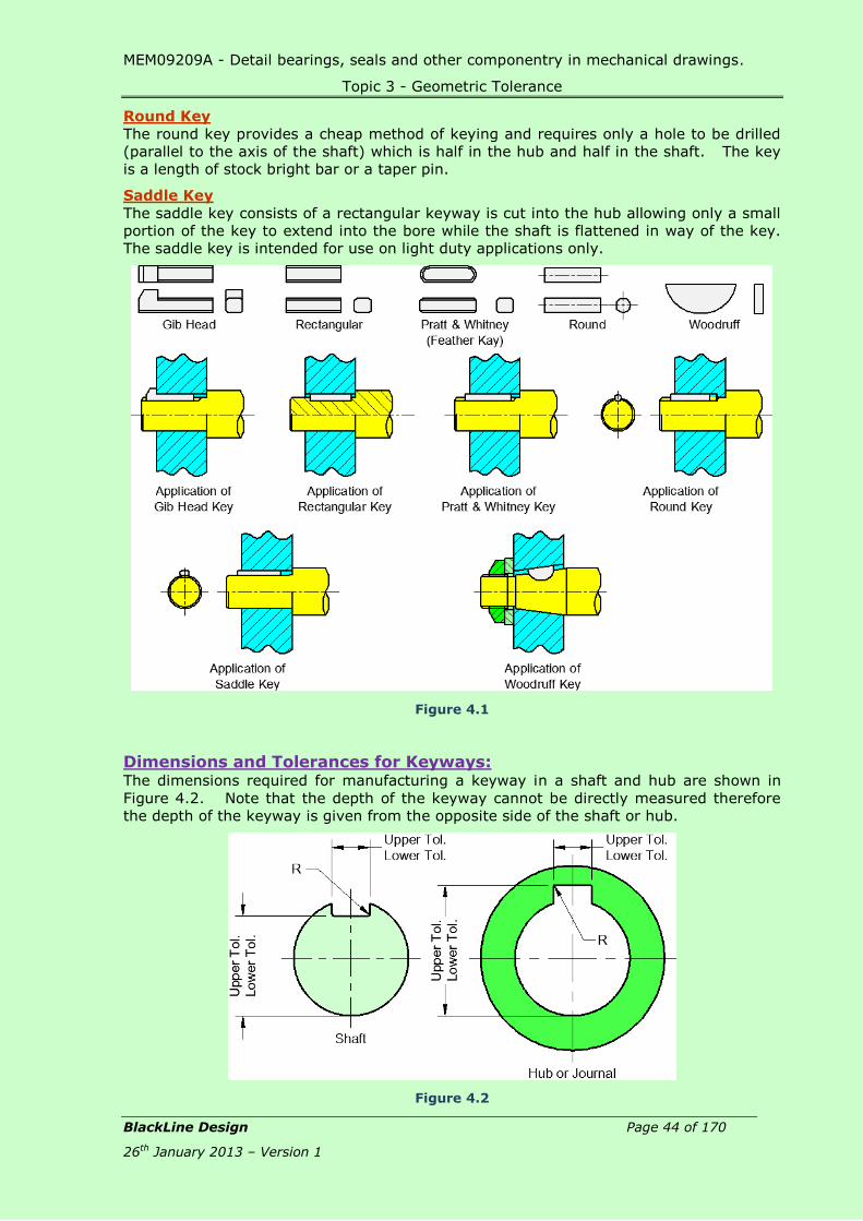
Keys & Keyways: Keys are used to provide positive drive between cylindrical elements such as gears and
pulleys on their shafts. A key is a piece of metal that is placed in a groove called the
“key seat”, cut in a shaft. The key extends above the shaft and fits into a “keyway” cut
into the hub. After assembly, the key locks the 2 parts together so that one cannot
rotate without the other thereby providing positive drive.
Rectangular Key
Rectangular keys consist of a piece of rectangular or square shaped section bar with
chamfered edges that have a slight taper to assist fitting. The keys are located in
rectangular slots or keyways that have been milled in the shaft to a depth of
approximately half that of the key. A corresponding keyway is machined in the bore of
the part to be keyed to the shaft.
Gib Head
The Gib head key is used at the end of a shaft and is tapered to give a rigid fixing when
hammered into place. A head is provided to assist removal of the key.
Woodruff Key
The Woodruff keys are used on tapered shafts and can be tilted for easy assembly. The
keys are semi-circular segment discs that fit into recesses of the same diameter.
Pratt and Whitney Key (Feather Key)
The Pratt and Whitney key is similar to the rectangular key but has radius ends and fits
into a keyway of the same shape on the shaft. The keyway in the hub is open at one or
both ends.
Rectangular Keys Gib Head Keys Woodruff Key Pratt &
Whitney Key
MEM09209A - Detail bearings, seals and other componentry in mechanical drawings.
Topic 3 - Geometric Tolerance
BlackLine Design Page 44 of 170
26th January 2013 – Version 1
Round Key
The round key provides a cheap method of keying and requires only a hole to be drilled
(parallel to the axis of the shaft) which is half in the hub and half in the shaft. The key
is a length of stock bright bar or a taper pin.
Saddle Key
The saddle key consists of a rectangular keyway is cut into the hub allowing only a small
portion of the key to extend into the bore while the shaft is flattened in way of the key.
The saddle key is intended for use on light duty applications only.
Figure 4.1
Dimensions and Tolerances for Keyways: The dimensions required for manufacturing a keyway in a shaft and hub are shown in
Figure 4.2. Note that the depth of the keyway cannot be directly measured therefore
the depth of the keyway is given from the opposite side of the shaft or hub.
Figure 4.2
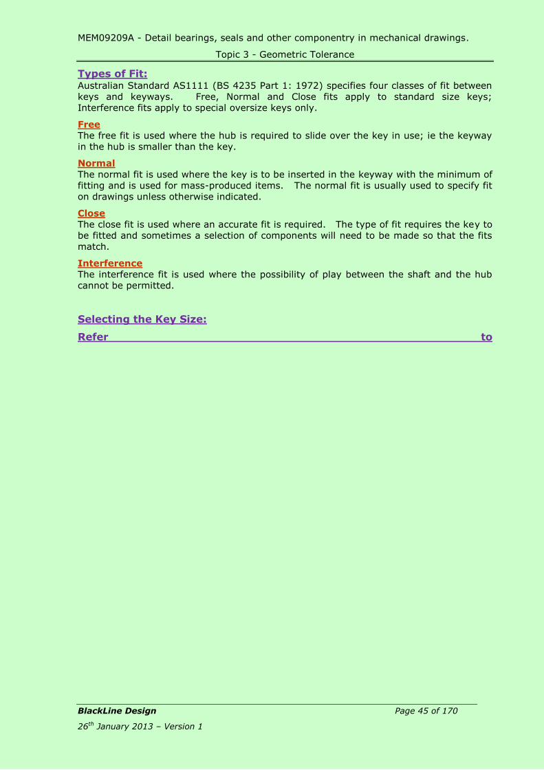
MEM09209A - Detail bearings, seals and other componentry in mechanical drawings.
Topic 3 - Geometric Tolerance
BlackLine Design Page 45 of 170
26th January 2013 – Version 1
Types of Fit: Australian Standard AS1111 (BS 4235 Part 1: 1972) specifies four classes of fit between
keys and keyways. Free, Normal and Close fits apply to standard size keys;
Interference fits apply to special oversize keys only.
Free
The free fit is used where the hub is required to slide over the key in use; ie the keyway
in the hub is smaller than the key.
Normal
The normal fit is used where the key is to be inserted in the keyway with the minimum of
fitting and is used for mass-produced items. The normal fit is usually used to specify fit
on drawings unless otherwise indicated.
Close
The close fit is used where an accurate fit is required. The type of fit requires the key to
be fitted and sometimes a selection of components will need to be made so that the fits
match.
Interference
The interference fit is used where the possibility of play between the shaft and the hub
cannot be permitted.
Selecting the Key Size:
Refer to
MEM09209A - Detail bearings, seals and other componentry in mechanical drawings.
Topic 4 – Keys, Keyways & Keyseats
BlackLine Design Page 46 of 170
26th January 2013 – Version 1
Table 21 – Dimensions and Tolerances for Keyways to determine the required sizes of
keyways.
The size of the key to be used is determined by the diameter of the shaft. Columns 1
and 2 of

MEM09209A - Detail bearings, seals and other componentry in mechanical drawings.
Topic 4 – Keys, Keyways and Keyseats
BlackLine Design Page 47 of 170
26th January 2013 – Version 1
Table 21 list a range of diameter sizes. Column 3 lists the key to be used for the shaft
size range.
Example 4-1:
Determine the size of a key to suit a shaft size of 32 mm diameter.
Figure 4.3
Procedure:
The shaft lies in the 30 mm (Column 1) to 38 mm (Column 2) nominal size range.
Reading from Column 3, it can be seen that a 10 mm x 8mm key will be used.

MEM09209A - Detail bearings, seals and other componentry in mechanical drawings.
Topic 4 – Keys, Keyways and Keyseats
BlackLine Design Page 48 of 170
26th January 2013 – Version 1
Example 4-2:
Determine the size of a key to suit a shaft size on 110 mm diameter.
Figure 4.4
Procedure:
Column 2 indicates shaft sizes up to and including those indicated; therefore the shaft
lies in the 95 mm to 110 mm range. The size of the key from Column 3 is 28 mm x 16
mm.
Selecting Shaft and Hub Dimensions and Tolerances:
Shaft and Hub Widths
The widths of the keyways in the shaft and hub are determined by locating the
tolerances for the designated class of fit to suit the nominal shaft diameter then applying
those tolerances to the width of the selected key.
Example 4-3:
Calculate the width of the keyway in the shaft and hub to suit a key on a 32 mm
diameter shaft. The key is to be a normal fit in the keyway.
Procedure:
The key as determined is 10 mm x 8 mm. Reading across the line to Columns 7 & 8
(Normal), the tolerances are shown as:
7 8
Shaft Hub
0 +0.018
-0.036 -0.018
Apply the tolerances to the width:
Shaft - Maximum = 10.000 + 0 = 10.000mm
Minimum = 10.000 – 0.036 = 9.964mm
Hub - Maximum = 10.000 + 0.018 = 10.018mm
Minimum = 10.000 – 0.018 = 9.982mm

MEM09209A - Detail bearings, seals and other componentry in mechanical drawings.
Topic 4 – Keys, Keyways and Keyseats
BlackLine Design Page 49 of 170
26th January 2013 – Version 1
Example 4-4:
Calculate the width of the keyway in the shaft and hub to suit a key on a 110 mm
diameter shaft. The key is to be a free fit in the keyway.
Procedure:
The key as determined is 28 mm x 16 mm. Reading across the line to Columns 5 & 6
(Free), the tolerances are shown as:
5 6
Shaft Hub
+0.052 +0.149
0 +0.065
Apply the tolerances to the width:
Shaft - Maximum = 32.000 + 0.052 = 32.052 mm
Minimum = 32.000 + 0 = 32.000 mm
Hub - Maximum = 32.000 + 0.149 = 32.149 mm
Minimum = 32.000 + 0.065 = 32.065 mm
Shaft and Hub Depths
The depth of the keyway is determined by reading the depths and tolerances from
Columns 10 to 13 and applying them to the following formula:
Shaft = Nominal Shaft Diameter – (Depth-Column 10 and Tolerance-Column 11)
Hub = Nominal Shaft Diameter + (Depth-Column 1 and Tolerance-Column 13)
Example 4-5:
Calculate the depth of the keyway in the shaft and hub to suit a key on a 32mm diameter
shaft.
Procedure:
The key as determined is 10 mm x 8 mm. Reading across the line to Columns 10 & 11,
to determine the depth of the shaft; the tolerances are shown as:
10 11
Nominal Tolerance
5 +0.2
0
Apply the tolerances to determine the shaft depth:
Shaft - Maximum = 32.00 – (5.000 + 0.2) = 26.80 mm
Minimum = 32.00 – (5.000 + 0) = 27.00 mm
Now read across the line to Columns 12 & 13, to determine the depth of the hub; the
tolerances are shown as:

MEM09209A - Detail bearings, seals and other componentry in mechanical drawings.
Topic 4 – Keys, Keyways and Keyseats
BlackLine Design Page 50 of 170
26th January 2013 – Version 1
12 13
Nominal Tolerance
3.3 +0.2
0
Apply the tolerances to determine the hub depth:
Hub - Maximum = 32.000 + (3.3 + 0.2) = 35.2 mm
Minimum = 32.000 + (3.3 + 0) = 35.0 mm
Example 4-6:
Calculate the depth of the keyway in the shaft and hub to suit a key on a 110 mm
diameter shaft.
Procedure:
The key as determined is 28 mm x 16 mm. Reading across the line to Columns 10 & 11,
to determine the depth of the shaft; the tolerances are shown as:
10 11
Nominal Tolerance.
10 +0.2
0
Apply the tolerances to determine the shaft depth:
Shaft - Maximum = 110.00 – (10.000 + 0.2) = 99.80 mm
Minimum = 110.00 – (10.000 + 0) = 100.00 mm
Now read across the line to Columns 12 & 13, to determine the depth of the hub; the
tolerances are shown as:
12 13
Nominal Tolerance
6.4 +0.2
0
Apply the tolerances to determine the hub depth:
Hub - Maximum = 110.000 + (6.4 + 0.2) = 116.6 mm
Minimum = 110.000 + (6.4 + 0) = 116.4 mm

MEM09209A - Detail bearings, seals and other componentry in mechanical drawings.
Topic 4 – Keys, Keyways and Keyseats
BlackLine Design Page 51 of 170
26th January 2013 – Version 1
Select the Keyway Corner Radius:
The maximum and minimum radii for the corners of the keyway on the shaft and hub are
determined by reading across to Columns 14 and 15.
Example 4-7:
Determine the radii of the keyway in the shaft and hub to suit a key on a 32 mm
diameter shaft.
Procedure:
Reading across the line to Columns 14 & 15, to determine the radii of the shaft and hub:
14 15
Maximum Minimum
0.40 0.25
Apply the radii to the drawing:
Figure 4.5
Example 4-8:
Calculate the depth of the keyway in the shaft and hub to suit a key on a 110 mm
diameter shaft.
Procedure:
Reading across the line to Columns 14 & 15, to determine the radii of the shaft and hub:
14 15
Maximum Minimum
0.60 0.40
Apply the radii to the drawing:
Figure 4.6

MEM09209A - Detail bearings, seals and other componentry in mechanical drawings.
Topic 4 – Keys, Keyways and Keyseats
BlackLine Design Page 52 of 170
26th January 2013 – Version 1
Review Questions: MEM09209-RQ-04
1. Define the following terminology:
Key
_________________________________________________________________
_________________________________________________________________
Keyway
_________________________________________________________________
_________________________________________________________________
Interference Fit
_________________________________________________________________
_________________________________________________________________
2. Name 4 types of key used in engineering applications.
a) ___________________________________________________________
b) ___________________________________________________________
c) ___________________________________________________________
d) ___________________________________________________________
3. List the 3 types of fit used for keys and keyways.
a) ___________________________________________________________
b) ___________________________________________________________
c) ___________________________________________________________
4. Use the Dimensions and Tolerances for Keyways Tables to select a key size to suit
a 64 mm diameter shaft.
_________________________________________________________________
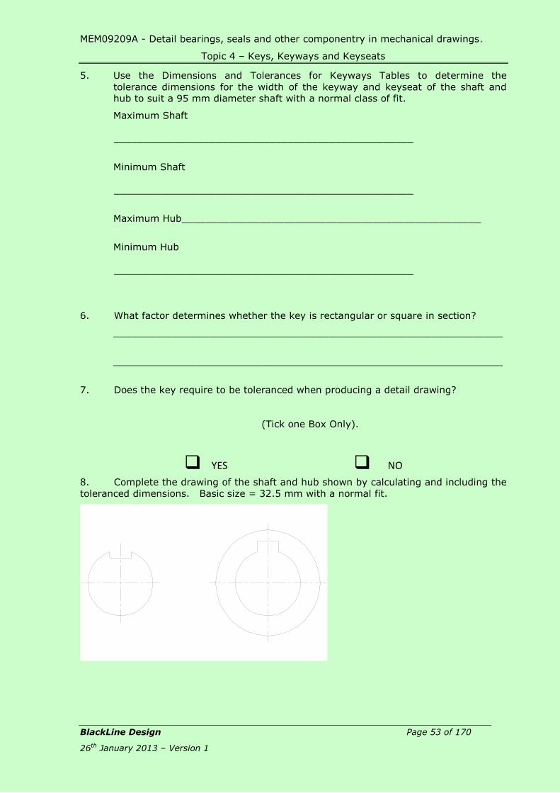
MEM09209A - Detail bearings, seals and other componentry in mechanical drawings.
Topic 4 – Keys, Keyways and Keyseats
BlackLine Design Page 53 of 170
26th January 2013 – Version 1
5. Use the Dimensions and Tolerances for Keyways Tables to determine the
tolerance dimensions for the width of the keyway and keyseat of the shaft and
hub to suit a 95 mm diameter shaft with a normal class of fit.
Maximum Shaft
__________________________________________________
Minimum Shaft
__________________________________________________
Maximum Hub __________________________________________________
Minimum Hub
__________________________________________________
6. What factor determines whether the key is rectangular or square in section?
_________________________________________________________________
_________________________________________________________________
7. Does the key require to be toleranced when producing a detail drawing?
(Tick one Box Only).
YES NO
8. Complete the drawing of the shaft and hub shown by calculating and including the
toleranced dimensions. Basic size = 32.5 mm with a normal fit.
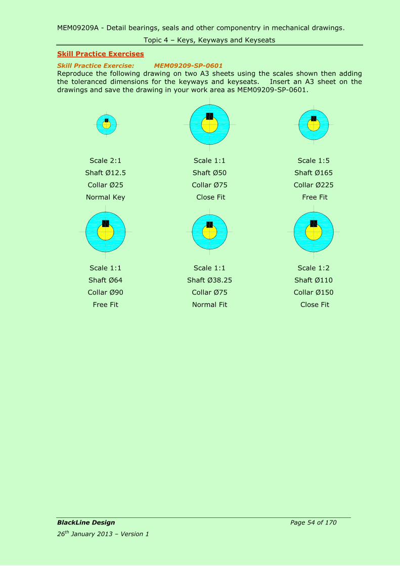
MEM09209A - Detail bearings, seals and other componentry in mechanical drawings.
Topic 4 – Keys, Keyways and Keyseats
BlackLine Design Page 54 of 170
26th January 2013 – Version 1
Skill Practice Exercises
Skill Practice Exercise: MEM09209-SP-0601
Reproduce the following drawing on two A3 sheets using the scales shown then adding
the toleranced dimensions for the keyways and keyseats. Insert an A3 sheet on the
drawings and save the drawing in your work area as MEM09209-SP-0601.
Scale 2:1
Shaft Ø12.5
Collar Ø25
Normal Key
Scale 1:1
Shaft Ø50
Collar Ø75
Close Fit
Scale 1:5
Shaft Ø165
Collar Ø225
Free Fit
Scale 1:1
Shaft Ø64
Collar Ø90
Free Fit
Scale 1:1
Shaft Ø38.25
Collar Ø75
Normal Fit
Scale 1:2
Shaft Ø110
Collar Ø150
Close Fit

MEM09209A - Detail bearings, seals and other componentry in mechanical drawings.
Topic 4 – Keys, Keyways and Keyseats
BlackLine Design Page 55 of 170
26th January 2013 – Version 1
Skill Practice Exercise: MEM09209-SP-0602
1. Create a new drawing using the template drawing called Gearbox and complete
the assembly by adding keyways to the shaft and gears.
2. Produce an assembly drawing of the Gearbox including a Parts List and cross-
referencing.
3. Produce separate detail drawings of the shaft and the various gears showing
details of the keyseat and keyway to suit a normal fit.
4. Indicate that all mating flat surfaces are to be milled to 1.6 and all curved
surfaces ground to 0.4. Holes are to be reamed to 0.1.
5. All flat mating flat surfaces are to be perpendicular to the datum centreline to
0.05 and a flatness of 0.1. All holes and curved surfaces are to be concentric to
the datum to 0.02 and straight to within 0.08.
6. Insert an A3 sheet to all drawings and submit to your teacher for correction.
7. Save the drawing as MEM09209-SP-0602.
The shape of the Housing is circular. All toleranced dimensions are to be placed on the
drawing as Limit of Size.
Materials are: Housing – Cast Iron, Shaft – Stainless Steel, Gears – Mild Steel, Pulley –
Cast Iron, Spacers – Brass, Fastenings – Commercial.

MEM09209A - Detail bearings, seals and other componentry in mechanical drawings.
Topic 4 – Keys, Keyways and Keyseats
BlackLine Design Page 56 of 170
26th January 2013 – Version 1
Skill Practice Exercise: MEM09209-SP-0603
1. Create a new drawing using the template drawing called Flexible Coupling and
complete the assembly by adding keyways to the shafts and couplings.
2. Produce an assembly drawing of the Flexible Coupling including a Parts List and
cross-referencing.
3. Produce separate detail drawings of the shaft, the HP and LP Couplings showing
details of the keyseat and keyway to suit a close fit.
4. Indicate that all mating flat surfaces are to be milled to 3.2 while all curved
surfaces are machined to 0.8. Holes are to be reamed to 0.05.
5. All flat mating flat surfaces are to be perpendicular to the datum centreline to
0.05 and a flatness of 0.1. All holes and curved surfaces are to be concentric to
the datum to 0.02 and straight to within 0.08.
6. Insert an A3 sheet to all drawings and submit to your teacher for correction.
7. Save the drawing as MEM09209-SP-0603.
The coupling is circular in shape and fastened using 6 machine screws/bolts equally
spaced on the PCD. All toleranced dimensions are to be placed on the drawing as Limit
of Size.
Materials are: HP & LP Coupling – Mild Steel, Shafts – Stainless Steel, Bushes – Nylon,
Keys – Mild Steel, Flexible Disc – Rubber.

MEM09209A - Detail bearings, seals and other componentry in mechanical drawings.
Tables
BlackLine Design Page 57 of 170
26th January 2013 – Version 1
Topic 5 – Hole & Shaft Basis Systems:
Required Skills:
Use the Hole Basis and Shaft Basis System Tables to determine the maximum
and minimum dimensions of a hole and shaft.
Produce a detail drawing of engineering components using the tables to
specify toleranced dimensions of holes and shafts
Required Knowledge:
The 2 of Basis Systems for assigning tolerances to shafts and holes.
Conversion of toleranced dimensions.
Application of toleranced dimensions.
Hole Basis System: The Hole Basis System, is a system of fits in which the different clearances and
interferences are obtained in associating various shafts with a single hole.
In the Hole basis system, the hole is kept with the basic size as one of its limits. The
shaft is then varied above or below the basic size to provide the fit required. The reason
for preferring this system is that it is easy to drill or ream a standard size hole. The
mating shaft can then be turned oversize or undersized as required. The alternative
would be to have standard size shafts and non-standard holes, which is more difficult and
costly.
To determine the toleranced dimensions for holes and shafts,

MEM09209A - Detail bearings, seals and other componentry in mechanical drawings.
Tables
BlackLine Design Page 58 of 170
26th January 2013 – Version 1
Table 17 - Hole Basis System must be referred to.
Example 5-1:
Determine the upper and lower values of a shaft and hub with a basic hole size of
Ø62 mm and a fit of H8-f7.
Procedure:
Refer to

MEM09209A - Detail bearings, seals and other componentry in mechanical drawings.
Topic 5 – Hole & Shaft Basis Systems
BlackLine Design Page 59 of 170
26th January 2013 – Version 1
1. Table 17 - Hole Basis System.
2. Locate the row where the diameter of the shaft lies – between 50 & 65.
3. Locate the columns containing the fit H8-f7.
4. Read the tolerances in the box intersecting the selected row and column.
H8 = +46 & 0 f7 = -30 & -60
The sizes are in micrometres (1/1000th mm)
5. Calculate the upper and lower values of the hole - H8:
Upper = 62.000 + 0.046 = 62.046 mm
Lower = 62.000 + 0.000 = 62.000 mm
6. Calculate the upper and lower values of the shaft – f7:
Lower = 62.000 – 0.060 = 61.940 mm
Upper = 62.000 – 0.030 = 61.970 mm
7. Apply the tolerance dimensions to the detail drawing.
Shaft Basis System: The Basic Shaft System is a system of fits in which the design size of the shaft is the
basic size and the allowance applies to the hole.
The shaft basis system of fits complements the hole basis system. With the shaft basis
system, the shaft is kept at a standard size and the hole size varied above or below the
standard size to provide the required fit. The shaft basis system has advantages where
a number of components have to be fitted onto one shaft. It is particularly suitable
where standard ground steel bar is used for the shaft.
To determine the toleranced dimensions for holes and shafts, Table 18 – Shaft Basis
System must be referred to.
Example 5-2:
Determine the upper and lower values of a shaft and hub with a basic shaft size of 62
mm and a fit of F8-h7.
Procedure:

MEM09209A - Detail bearings, seals and other componentry in mechanical drawings.
Topic 5 – Hole & Shaft Basis Systems
BlackLine Design Page 60 of 170
26th January 2013 – Version 1
1. Refer to Table 18 – Shaft Basis System.
2. Locate the row where the diameter of the shaft lies – between 50 & 65.
3. Locate the columns containing the fit F8-h7.
4. Read the tolerances in the box intersecting the selected row and column.
F8 = +76 & +30 f7 = 0 & -30
5. The sizes are in micrometres (1/1000th mm)
6. Calculate the upper and lower values of the hole - F8:
Upper = 62.000 + 0.076 = 62.076 mm
Lower = 62.000 + 0.030 = 62.030 mm
7. Calculate the upper and lower values of the shaft – h7:
Lower = 62.000 – 0 = 62.000 mm
Upper = 62.000 – 0.030 = 61.970 mm
8. Apply the tolerance dimensions to the detail drawing.
Note:
Although both the Hole and Shaft Basis Systems are equivalent in the view of their
functional properties, the Hole Basis System is preferably used.
Classification of Fits: The table below indicates that switching the letters in the fit makes the conversion from
hole to shaft basis. (Note that the hole fit always has the capital letter.) There is only
one exception to the rule and that is where H9-d10 converts to D10-h9 for a loose
running fit.
Clearance Fit:
A Clearance fit is a fit that always enables a clearance between the hole and shaft in the
coupling. The lower limit size of the hole is greater or at least equal to the upper limit
size of the shaft.
H11/a11, H11/c11, H11/c9, H11/d11, A11/h11, C11/h11, D11/h11
Fits with great clearances with parts having great tolerances.
Use: Pivots, latches, fits of parts exposed to corrosive effects,
contamination with dust and thermal or mechanical deformations.
H9/C9, H9/d10, H9/d9, H8/d9, H8/d8, D10/h9, D9/h9, D9/h8
Running fits with greater clearances without any special requirements for
accuracy of guiding shafts.

MEM09209A - Detail bearings, seals and other componentry in mechanical drawings.
Topic 5 – Hole & Shaft Basis Systems
BlackLine Design Page 61 of 170
26th January 2013 – Version 1
Use: Multiple fits of shafts of production and piston machines, parts
rotating very rarely or only swinging.
H9/e9, H8/e8, H7/e7, E9/h9, E8/h8, E8/h7
Running fits with greater clearances without any special requirements for
fit accuracy.
Use: Fits of long shafts, e.g. in agricultural machines, bearings of pumps,
fans and piston machines.
H9/f8, H8/f8, H8/f7, H7/f7, F8/h7, F8/h6
Running fits with smaller clearances with general requirements for fit
accuracy.
Use: Main fits of machine tools. General fits of shafts, regulator bearings,
machine tool spindles, sliding rods.
H8/g7, H7/g6, G7/h6
Running fits with very small clearances for accurate guiding of shafts.
Without any noticeable clearance after assembly.
Use: Parts of machine tools, sliding gears and clutch disks, crankshaft
journals, pistons of hydraulic machines, rods sliding in bearings, grinding
machine spindles.
H11/h11, H11/h9
Slipping fits of parts with great tolerances. The parts can easily be slid one
into the other and turn.
Use: Easily demountable parts, distance rings, parts of machines fixed to
shafts using pins, bolts, rivets or welds.
H8/h9, H8/h8, H8/h7, H7/h6
Sliding fits with very small clearances for precise guiding and centring of
parts. Mounting by sliding on without use of any great force, after
lubrication the parts can be turned and slid by hand.
Use: Precise guiding of machines and preparations, exchangeable wheels,
roller guides.
Transition Fit:
A Trancisi0on fit is a fit where (depending on the actual sizes of the hole and shaft) both
clearance and interference may occur in the coupling. Tolerance zones of the hole and
shaft partly or completely interfere.
H8/j7, H7/js6, H7/j6, J7/h6
Tight fits with small clearances or negligible interference. The parts can be
assembled or disassembled manually.
Use: Easily dismountable fits of hubs of gears, pulleys and bushings,
retaining rings, frequently removed bearing bushings.
H8/k7, H7/k6, K8/h7, K7/h6
Similar fits with small clearances or small interferences. The parts can be
assembled or disassembled without great force using a rubber mallet.
Use: Demountable fits of hubs of gears and pulleys, manual wheels,
clutches, brake disks.
H8/p7, H8/m7, H8/n7, H7/m6, H7/n6, M8/h6, N8/h7, N7/h6
Fixed fits with negligible clearances or small interferences. Mounting of fits
using pressing and light force.

MEM09209A - Detail bearings, seals and other componentry in mechanical drawings.
Topic 5 – Hole & Shaft Basis Systems
BlackLine Design Page 62 of 170
26th January 2013 – Version 1
Use: Fixed plugs, driven bushings, armatures of electric motors on shafts,
gear rims, flushed bolts.
Interference Fit:
An Interference fit is a fit always ensuring some interference between the hole and shaft
in the coupling. The upper limit size of the hole is smaller or at least equal to the lower
limit size of the shaft.
H8/r7, H7/p6, H7/r6, P7/h6, R7/h6
Pressed fits with guaranteed interference. Assembly of the parts can be
carried out using cold pressing.
Use: Hubs of clutch disks, bearing bushings.
H8/s7, H8/t7, H7/s6, H7/t6, S7/h6, T7/h6
Pressed fits with medium interference. Assembly of parts using hot
pressing. Assembly using cold pressing only with use of large forces.
Use: Permanent coupling of gears with shafts, bearing bushings.
H8/u8, H8/u7, H8/x8, H7/u6, U8/h7, U7/h6
Pressed fits with big interferences. Assembly using pressing and great
forces under different temperatures of the parts.
Use: permanent couplings of gears with shafts, flanges.
Fit Hole Basis
Specification
Shaft Basis
Specification
Loose Clearance H11 - c11 C11 – h11
Loose Running H9 – d10 D10 – h9
Easy Running H9 - e9 E9 – h9
Normal Running H8 – f7 F8 – h7
Precision Running H7 – g6 G7 – h6
Average Location H7 – h6 H7 – h6
Light Push H7 – k6 K7 - h6
Heavy Push H7 – n6 N7 – h6
Press (Ferrous) H7 – p6 P7 - h6
Press (Non Ferrous) H7 – s6 S7 - h6

MEM09209A - Detail bearings, seals and other componentry in mechanical drawings.
Topic 5 – Hole & Shaft Basis Systems
BlackLine Design Page 63 of 170
26th January 2013 – Version 1
Review Questions: MEM09209-RQ-05
1. Why would a Shaft Basis System be used in preference to a Hole Basis System?
_________________________________________________________________
_________________________________________________________________
2. Calculate the missing dimensions of the shaft and hub by using the Hole Basis
System Table. Complete the drawing by including the toleranced dimensions.
3. Calculate the missing dimensions of the shaft and hub by using the Shaft Basis
System Table. Complete the drawing by including the toleranced dimensions.
4. What are the units of tolerance listed in the Hole and Shaft Basis tables?
_________________________________________________________________

MEM09209A - Detail bearings, seals and other componentry in mechanical drawings.
Topic 5 – Hole & Shaft Basis Systems
BlackLine Design Page 64 of 170
26th January 2013 – Version 1
Skill Practice Exercises
Skill Practice Exercise: MEM09209-SP-0501
1. Create a new drawing using the template drawing called Drive Shaft.
2. Produce an assembly drawing of the Flexible Coupling including a Parts List and
cross-referencing.
3. Produce separate detail drawings of the Shaft, Gear and Bushes showing details
for the keyseats and keyways to suit a normal fit.
4. Indicate that all mating flat surfaces are to be milled to 1.6 while all curved
surfaces are machined to 0.4. Holes are to be reamed to 0.02.
5. All flat mating flat surfaces are to be perpendicular to the datum centreline to
0.025 and a flatness of 0.15. All holes and curved surfaces are to be concentric to
the datum to 0.08 and straight to within 0.12.
6. Insert an A3 sheet to all drawings and submit to your teacher for correction.
7. Save the drawing as MEM09209-SP-0501.
The Housing can be assumed to be circular. All toleranced dimensions are to be placed
on the drawing as Limit of Size.
Materials: Shaft –Mild Steel; Bushes – Brass; Keys – Commercial; Gears – Mild Steel
Gear Representation:
Tip Diameter – 0.5 Visible Outline
Shaft Diameter – 0.5 Visible Outline
Reference Diameter – 0.25 Centreline
Root Diameter – 0.25 Visible Outline

MEM09209A - Detail bearings, seals and other componentry in mechanical drawings.
Topic 5 – Hole & Shaft Basis Systems
BlackLine Design Page 65 of 170
26th January 2013 – Version 1
Skill Practice Exercise: MEM09209-SP-0502
1. Create a new drawing using the template drawing called Bench Pulley.
2. Produce an assembly drawing of the Bench Pulley including a Parts List and cross-
referencing.
3. Produce separate detail drawings of the Yoke, Pulley and Base.
4. Assign toleranced dimensions to suit the following:
Pulley to Yoke H11-c11
Yoke to Base H9-d10
5. Indicate that all mating flat surfaces are to be machined to 0.8 while all mating
curved surfaces are ground to 0.2. Holes are to be reamed to 0.05.
6. All flat mating flat surfaces are to be perpendicular to the datum centreline to
0.025 and a flatness of 0.15. All holes and curved surfaces are to be concentric to
the datum to 0.08 and straight to within 0.12.
7. Insert an A3 sheet to all drawings and submit to your teacher for correction.
8. Save the drawing as MEM09209-SP-0502.
All toleranced dimensions are to be placed on the drawing as Limit of Size.
Materials: Base – Cast Iron; Yoke – Mild Steel; Pulley – Bronze; Fastenings –
Commercial.
MEM09209A - Detail bearings, seals and other componentry in mechanical drawings.
Topic 6 – Plain Bearings
BlackLine Design Page 66 of 170
26th January 2013 – Version 1
Topic 6 – Plain Bearings:
Required Skills:
Produce assembly and detail drawings of components containing plain
bearings.
Prepare detail drawings of components mating with bearings.
Required Knowledge:
Classifications of bearings.
The use and applications of bearings in engineering.
Materials used in the manufacture of bearings.
Bearings: Bearings are used to reduce friction and wear, or constrict and restrain motion of
mechanical components. Shafts are supported by bearings and form an integral part of
power transmission. The shafts are designed to enable the bearings to be lubricated
and adjusted so that only the minimal amount of work is expended in overcoming
frictional resistance to motion. The relationship between the size of the shaft and
bearing is arranged to allow a “running fit”. A lubricant is used to reduce the amount of
undue heating that could lead to the seizure of the moving parts through expansion.
Bearings can be dated to 1100BC where friction was reduced by inserting rollers between
the object and the surface over which it was to be moved. The Egyptians, Assyrians and
Babylonians used rollers to move enormous stones for their pyramids, monuments and
palaces.
Classification of Bearings: Shaft bearings may be journal bearings (the term ‘journal’ refers to the shaft) that takes
the radial (perpendicular to the shaft) forces, or thrust bearings which take axial (parallel
to the shaft) forces. There are two main classifications of journal and thrust bearings:
sliding contact are plain sleeves and rolling contact, which consist of rollers or balls.
Sliding Contact Bearings: Sliding Contact type bearings are commonly known as Plain Bearings and work with or
without lubrication. Plain bearings incorporate fundamentally all types other than rolling
contact bearings and are often referred to as sleeve bearings or thrust bearings, terms
that designate whether the bearing is loaded axially or radially. There are 4 types of
Sliding Contact Bearings; Plain Journal or Sleeve Bearing, Pedestal Bearing, Footstep
Thrust Bearing and the Plain Thrust Bearing. Sliding contact bearings are relatively
simple and hence inexpensive. They are compact, lightweight, simple to repair or
replace and have high load-carrying capacity. However, if operating in dry conditions
plain bearings may wear faster and have higher friction than rolling bearings. A common
plain bearing design is to use a hardened and polished steel shaft and a soft bronze
bushing. The design allows for the softer metal to be worn away and periodically
changed during regular maintenance.
Plain Journal or Sleeve Bearings:
A typical Plain Bearing is made from two sleeves or a solid bush. Plain bearings may
carry loads in one of several ways depending on their operating conditions, load, relative
surface speed (shaft to journal), clearance within the bearing, quality and quantity of
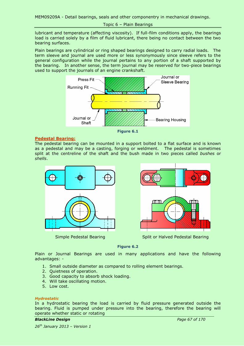
MEM09209A - Detail bearings, seals and other componentry in mechanical drawings.
Topic 6 – Plain Bearings
BlackLine Design Page 67 of 170
26th January 2013 – Version 1
lubricant and temperature (affecting viscosity). If full-film conditions apply, the bearings
load is carried solely by a film of fluid lubricant, there being no contact between the two
bearing surfaces.
Plain bearings are cylindrical or ring shaped bearings designed to carry radial loads. The
term sleeve and journal are used more or less synonymously since sleeve refers to the
general configuration while the journal pertains to any portion of a shaft supported by
the bearing. In another sense, the term journal may be reserved for two-piece bearings
used to support the journals of an engine crankshaft.
Figure 6.1
Pedestal Bearing:
The pedestal bearing can be mounted in a support bolted to a flat surface and is known
as a pedestal and may be a casting, forging or weldment. The pedestal is sometimes
split at the centreline of the shaft and the bush made in two pieces called bushes or
shells.
Simple Pedestal Bearing
Split or Halved Pedestal Bearing
Figure 6.2
Plain or Journal Bearings are used in many applications and have the following
advantages: -
1. Small outside diameter as compared to rolling element bearings.
2. Quietness of operation.
3. Good capacity to absorb shock loading.
4. Will take oscillating motion.
5. Low cost.
Hydrostatic
In a hydrostatic bearing the load is carried by fluid pressure generated outside the
bearing. Fluid is pumped under pressure into the bearing, therefore the bearing will
operate whether static or rotating

MEM09209A - Detail bearings, seals and other componentry in mechanical drawings.
Topic 6 – Plain Bearings
BlackLine Design Page 68 of 170
26th January 2013 – Version 1
Hydrodynamic
In a hydrodynamic bearing a fluid is drawn into the region between the moving parts of
the bearing by the virtue of its adhesion to the surfaces of the bearing and its viscosity
and due to the shape of the bearing surfaces a pressure is generated within the fluid
which keeps the bearing surfaces separated. The separating film is only generated when
the there is relative motion in the bearing, i.e. when the shaft is rotating.
Boundary Lubrication
If the working fluid in a bearing adheres to or "wets" the bearing surfaces then some
load may be carried. Boundary lubrication will apply at low speeds but as the speed
increases some degree of hydrodynamic lubrication will be needed.
Dry Bearing
Dry bearings operate without a significant fluid film to separate the moving surfaces
therefore low friction materials, or materials impregnated with a lubricant, must be used.
Footstep Thrust Bearing:
The Footstep Thrust Bearing is used for the
lower end of a vertical shaft. A bush takes
the horizontal load and a hardened steel
pad takes the weight of the shaft or any
thrust.
Figure 6.3
Plain Thrust Bearing:
The Plain Thrust Bearing consists of a flat
ring or brass, bronze, etc., taking the axial
thrust on a shaft via a collar.
Figure 6.4
Plummer Block Dry Bearing Sleeve
Figure 6.5
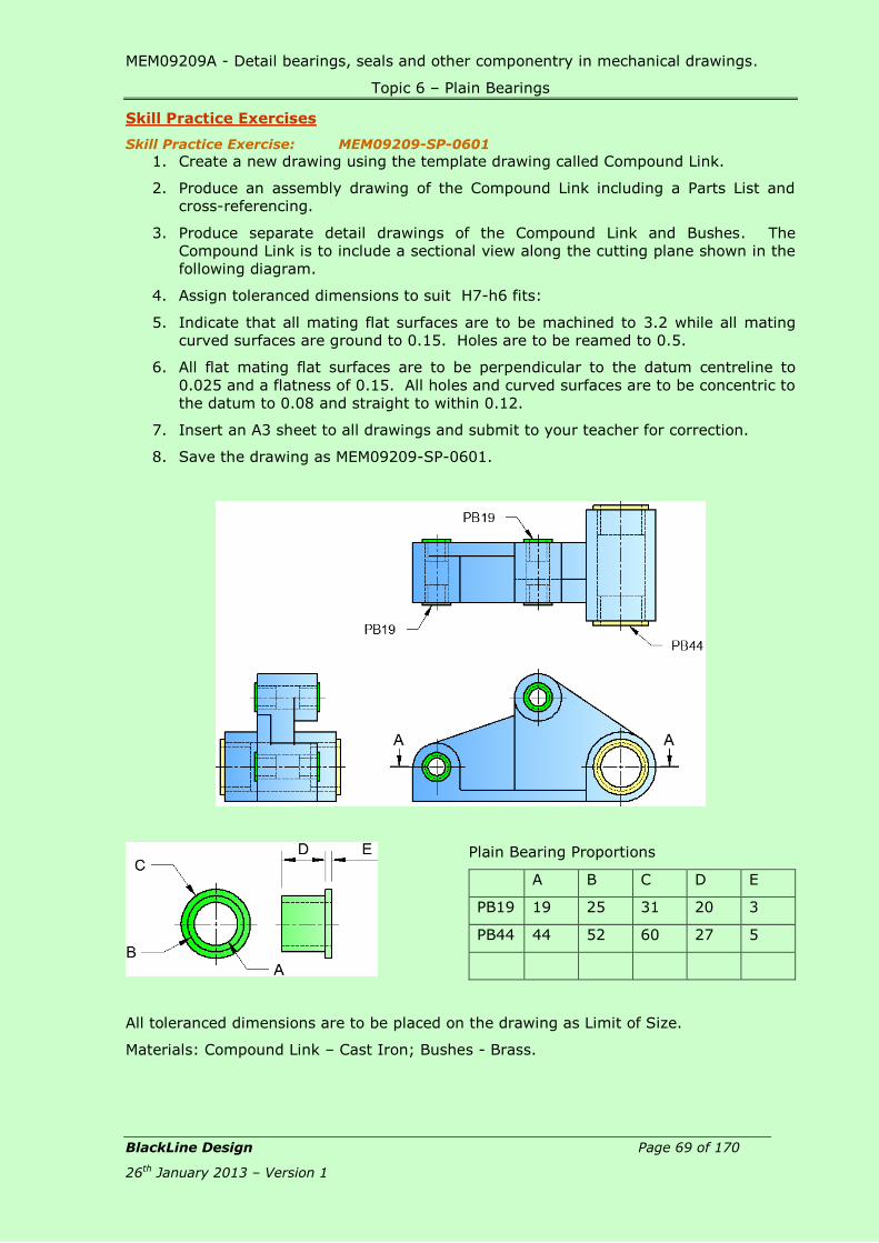
MEM09209A - Detail bearings, seals and other componentry in mechanical drawings.
Topic 6 – Plain Bearings
BlackLine Design Page 69 of 170
26th January 2013 – Version 1
Skill Practice Exercises
Skill Practice Exercise: MEM09209-SP-0601
1. Create a new drawing using the template drawing called Compound Link.
2. Produce an assembly drawing of the Compound Link including a Parts List and
cross-referencing.
3. Produce separate detail drawings of the Compound Link and Bushes. The
Compound Link is to include a sectional view along the cutting plane shown in the
following diagram.
4. Assign toleranced dimensions to suit H7-h6 fits:
5. Indicate that all mating flat surfaces are to be machined to 3.2 while all mating
curved surfaces are ground to 0.15. Holes are to be reamed to 0.5.
6. All flat mating flat surfaces are to be perpendicular to the datum centreline to
0.025 and a flatness of 0.15. All holes and curved surfaces are to be concentric to
the datum to 0.08 and straight to within 0.12.
7. Insert an A3 sheet to all drawings and submit to your teacher for correction.
8. Save the drawing as MEM09209-SP-0601.
Plain Bearing Proportions
A B C D E
PB19 19 25 31 20 3
PB44 44 52 60 27 5
All toleranced dimensions are to be placed on the drawing as Limit of Size.
Materials: Compound Link – Cast Iron; Bushes - Brass.

MEM09209A - Detail bearings, seals and other componentry in mechanical drawings.
Topic 6 – Plain Bearings
BlackLine Design Page 70 of 170
26th January 2013 – Version 1
Skill Practice Exercise: MEM09209-SP-0602
1. Create a new drawing using the template drawing called Gland Bearing.
2. Produce an assembly drawing of the Gland Bearing including a Parts List and
cross-referencing.
3. Produce separate detail drawings of the Housing and Bushes. The drawings are to
include a sectional view along the cutting plane.
4. Assign toleranced dimensions to suit G7-h6 between the Bearings, Shaft and
Housing.
5. Indicate that all mating flat surfaces are to be machined to 6.4 while all mating
curved surfaces are ground to 1.6. Holes are to be reamed to 0.4.
6. All flat mating flat surfaces are to be perpendicular to the datum centreline to
0.02 and a flatness of 0.1. All holes and curved surfaces are to be concentric to
the datum to 0.1 and straight to within 0.15.
7. Insert an A3 sheet to all drawings and submit to your teacher for correction.
8. Save the drawing as MEM09209-SP-0602.
All toleranced dimensions are to be placed on the drawing as Limit of Size.
Materials: Shaft – Mild Steel; Housing – Mild Steel; Bushes - Brass.

MEM09209A - Detail bearings, seals and other componentry in mechanical drawings.
Topic 7 – Rolling Contact Bearings
BlackLine Design Page 71 of 170
26th January 2013 – Version 1
Topic 7 – Rolling Contact Bearings:
Required Skills:
Apply symbols of rolling contact bearings to detail drawings.
Select appropriate rolling contact bearing from manufacturer’s specifications
and catalogues.
Produce assembly drawings containing rolling contact bearings.
Produce detail drawings of components required to fit a rolling contact
bearing.
Produce detail drawings for retaining rolling contact bearings.
Required Knowledge:
Identify, draw the symbol and list the applications of 8 types of rolling contact
bearings.
Name the materials used in the manufacture of rolling contact bearings.
List the different methods of retaining bearings in position.
Rolling Contact Bearings: Rolling Contact Bearings cover a large range of bearings in which hardened steel balls or
rollers run between housings (or races) on the shaft and the fixed member. Roller
contact type bearings are often termed anti-friction bearings because of their extremely
low frictional resistance, especially at low speeds. Ball and roller bearings, although
more complicated than plain bearings, compare favourably in price when made in large
quantities. There are 3 types of Rolling Contact Bearings; Ball Bearings, Roller Bearings
and Thrust Bearings.
Ball Bearings: Ball bearings use spheres or balls contained between inner and outer cases. The balls
can be manufactured cheaper than roller type bearings. Ball bearings can support both
radial (perpendicular to the shaft) and axial (parallel to the shaft) loads. And offer lower
friction than rollers. Ball bearings can operate when the bearing races are misaligned.
Ball bearings consist of Single Row Deep Groove Ball Bearings, Double Row Deep Groove
Ball Bearings, Self-Aligning Bearings and Angular Contact Bearings.
Single Row Deep Groove Ball Bearings
Single row deep groove ball bearings are particularly versatile, simple in design, non-
separable, suitable for high and even very high speeds and are robust in operation,
requiring little maintenance. Deep raceway grooves and the close conformity between
the raceway grooves and the balls enable deep groove ball bearings to accommodate
axial loads in both directions, in addition to radial loads, even at high speeds. Single
row deep groove ball bearings are the most widely used bearing type.

MEM09209A - Detail bearings, seals and other componentry in mechanical drawings.
Topic 7 – Rolling Contact Bearings
BlackLine Design Page 72 of 170
26th January 2013 – Version 1
Single Row
Ball Bearing
Single Row
Ball Bearing
Symbol
Refer to Table 3 – Deep Groove Ball Bearings for dimensions.
Double Row Deep Groove Ball Bearings:
Double row deep groove ball bearings correspond in design to single row deep groove
ball bearings; they have deep uninterrupted raceways and high conformity between balls
and raceways. Double row deep groove ball bearings can carry axial loads acting in both
directions in addition to radial loads. Double row deep groove ball bearings are suitable
for bearing arrangements where the load carrying capacity of a single row bearing is
inadequate. For the same outside and bore diameters, double row deep groove ball
bearings are slightly wider and have considerably higher load carrying capacity than
single row bearings in the 62 and 63 series.
Double Row
Ball Bearing
Double Row
Ball Bearing
Symbol
Refer to Table 4 – Self Aligning Ball Bearings for dimensions.
Self-aligning Bearing:
The elf-aligning bearing normally has double rows of balls however they are available in
single rows of balls and a common concave spherical raceway in the outer ring. The
bearing is consequently self-aligning and insensitive to angular misalignments of the
shaft relative to the housing. It is particularly suitable for applications where
considerable shaft deflections or misalignments are to be expected. Additionally, the
bearing has the lowest friction of rolling bearings, which enables it to run cool even at
high speeds.
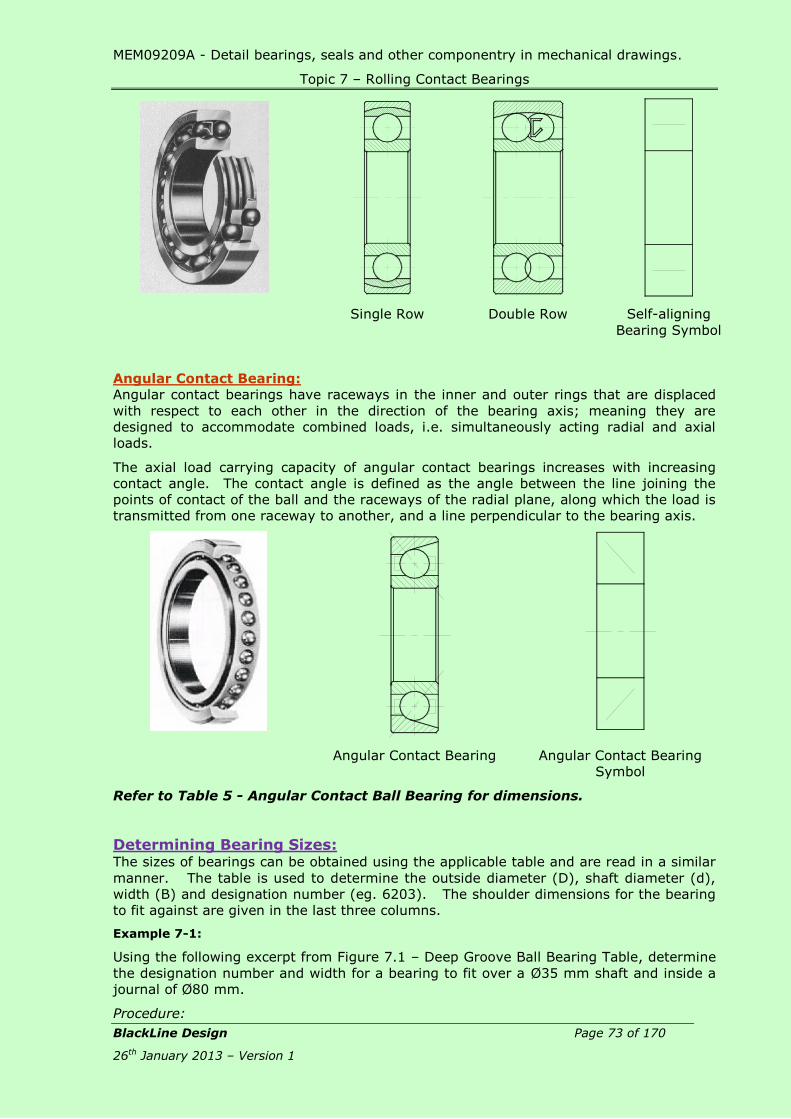
MEM09209A - Detail bearings, seals and other componentry in mechanical drawings.
Topic 7 – Rolling Contact Bearings
BlackLine Design Page 73 of 170
26th January 2013 – Version 1
Single Row Double Row Self-aligning
Bearing Symbol
Angular Contact Bearing:
Angular contact bearings have raceways in the inner and outer rings that are displaced
with respect to each other in the direction of the bearing axis; meaning they are
designed to accommodate combined loads, i.e. simultaneously acting radial and axial
loads.
The axial load carrying capacity of angular contact bearings increases with increasing
contact angle. The contact angle is defined as the angle between the line joining the
points of contact of the ball and the raceways of the radial plane, along which the load is
transmitted from one raceway to another, and a line perpendicular to the bearing axis.
Angular Contact Bearing Angular Contact Bearing
Symbol
Refer to Table 5 - Angular Contact Ball Bearing for dimensions.
Determining Bearing Sizes: The sizes of bearings can be obtained using the applicable table and are read in a similar
manner. The table is used to determine the outside diameter (D), shaft diameter (d),
width (B) and designation number (eg. 6203). The shoulder dimensions for the bearing
to fit against are given in the last three columns.
Example 7-1:
Using the following excerpt from Figure 7.1 – Deep Groove Ball Bearing Table, determine
the designation number and width for a bearing to fit over a Ø35 mm shaft and inside a
journal of Ø80 mm.
Procedure:

MEM09209A - Detail bearings, seals and other componentry in mechanical drawings.
Topic 7 – Rolling Contact Bearings
BlackLine Design Page 74 of 170
26th January 2013 – Version 1
Look down the first column of principle dimensions (d) and locate the 35; it can be seen
that the outside diameters in column 2 can be 47,62,72,80 or 100. Reading across the
80 row, the third column indicates the thickness (B) as 21 mm and in the designation
column, the bearing number is 6307; the shoulder radius (r) is 1.5 mm.
Principal Dimensions
Basic Load Settings
Limit Speeds Mass Designation
Dimensions Abutment
and Fillet Dimensions
Lubrication mm mm
d D B C Co Grease Oil d1 D1 D2 r
min da
min Da
max ra
max
mm N R/min Kg mm mm
30 52 7 3120 2080 15000 18000 0.026 61806 33.8 38.2 - 0.3 32 40 0.3
55 9 11200 5850 12000 15000 0.085 16006 38 47.3 - 0.3 32 53 0.3
55 13 13300 6800 12000 15000 0.12 6006 38.2 47.1 49 1 35 50 1
62 16 19500 10000 10000 13000 0.20 6206 40.3 52.1 54.1 1 35 57 1
72 19 28100 14600 9000 11000 0.35 6306 44.6 59.9 61.9 1.1 36.5 65.5 1
90 23 43600 24000 8500 10000 0.74 6406 50.3 70.7 - 1.5 38 82 1.5
35 47 7 4030 3000 13000 16000 0.030 61807 38.8 43.2 - 0.3 37 45 0.3
62 9 12400 6950 10000 13000 0.11 16007 44 53.3 - 0.3 37 60 0.3
62 14 15900 8500 10000 13000 0.16 6007 43.7 53.6 55.7 1 40 57 1
72 17 25500 13700 9000 11000 0.29 6207 46.9 60.6 62.7 1.1 41.5 65.5 1
80 21 33200 18000 8500 10000 0.46 6307 49.5 66.1 69.2 1.5 43 72 1.5
100 25 55300 31000 7000 8500 0.95 6407 57.4 80.6 - 1.5 43 92 1.5
40 52 7 4160 3350 11000 14000 0.034 61808 43.8 48.2 - 0.3 42 50 0.3
68 9 13300 7800 9500 12000 0.13 16008 49.4 57 - 0.3 42 66 0.3
68 15 16800 9300 9500 12000 0.19 6008 49.2 59.1 61.1 1 45 63 1
80 18 30700 16600 8500 10000 0.37 6208 52.6 67.9 69.8 1.1 46.5 73.5 1
90 23 41000 22400 7500 9000 0.63 6308 56.1 74.7 77.7 1.5 48 82 1.5
110 27 63700 36500 6700 8000 1.25 6408 62.8 88 - 2 49 101 2
Figure 7.1 – Deep Groove Ball Bearing Table

MEM09209A - Detail bearings, seals and other componentry in mechanical drawings.
Topic 7 – Rolling Contact Bearings
BlackLine Design Page 75 of 170
26th January 2013 – Version 1
Skill Practice Exercise:
Skill Practice Exercise: MEM09209-SP-0701
1. Create a new drawing using the template drawing called Cup Center Assembly
and complete the assembly by adding the hatching and bearing where shown.
2. Produce an assembly drawing of the Cup Center Assembly including a Parts List
and cross-referencing.
3. Produce separate detail drawings of the Centre Piece and Sleeve. One of the
views of the Centre Piece and Sleeve is to include a full or half sectional view
along the cutting plane.
4. Assign toleranced dimensions to suit P7-h6 between the fit between the bearing,
Sleeve and Center Piece.
5. All cylindrical surfaces for the bearings are to be reamed to a finish of 0.25, be
concentric to the datum centreline to 0.05 and roundness to 0.8.
6. All straight mating surfaces are to be milled to 0.4 and perpendicular to the
centreline to 0.5.
7. Insert an A3 sheet to all drawings and submit to your teacher for correction.
8. Save the drawing as MEM09209-SP-0701.
The coupling is circular in shape and fastened using 6 machine screws/bolts equally
spaced on the PCD. All toleranced dimensions are to be placed on the drawing as Limit
of Size.
Materials: Centre Piece – Mild Steel; Sleeve – Mild Steel; Bearing Spacer – Brass;
Rearing Retaining Cap – Mild Steel; End Screw Cap – Mild Steel; Fasteners and Bearing –
Commercial.

MEM09209B – Detail Drafting 2
Topic 7 – Rolling Contact Bearings
BlackLine Design Page 76 of 170
26th January 2013 – Version 1
Skill Practice Exercise: MEM09209-SP-0702
1. Create a new drawing using the template drawing called Wheel Hub and complete
the assembly by adding the hatching and bearing where shown.
2. Produce an assembly drawing of the Wheel Hub including a Parts List and cross-
referencing.
3. Produce separate detail drawings of the Hub. One of the views of the Centre
Piece and Sleeve is to include a full sectional view along a cutting plane.
4. All cylindrical surfaces for the bearings are to be reamed to a finish of 0.8, be
concentric to the datum centreline to 0.05 and roundness to 0.02.
5. All straight mating surfaces are to be milled to 0.4 and perpendicular to the
centreline to 0.1.
6. Insert an A3 sheet to all drawings and submit to your teacher for correction.
7. Save the drawing as MEM09209-SP-0702.
The coupling is circular in shape. All toleranced dimensions are to be placed on the
drawing as Limit of Size.
Material: Hub – Cast Iron; Shaft – Mild Steel; Support Ring – Bronze; Fasteners &
Bearings – Commercial.

MEM09209A - Detail bearings, seals and other componentry in mechanical drawings.
Topic 8 – Bearing Retention
BlackLine Design Page 77 of 170
26th January 2013 – Version 1
Topic 8 – Bearing Retention:
Required Skills:
Produce assembly drawings containing bearing retainers.
Produce detail drawings of components requiring bearing retention.
Required Knowledge:
Methods of retaining bearings in position.
Reading circlip tables.
Application of toleranced dimensions.
Retention of Bearings: When fixing a bearing in position on a shaft or in a hub, journal or housing, there are
many instances where the interference fit alone is not enough to hold the bearing in
place. The bearing must be fixed in place by various methods so they do not move
axially when placed under load. The most common method of fixing bearings in place is
to hold the ring end face against the shoulder of the shaft or housing abutment by means
of snap rings, circlips, bolts or screws.
Figure 8.1 Figure 8.2 Figure 8.3
Figure 8.1 illustrates inner ring clamping methods, while Figure 8.2 and Figure 8.3 show
outer ring clamping methods.
Figure 8.4 Figure 8.5
Figure 8.4 and Figure 8.5 show the use of snap ring/circlip methods which makes the
construction and assembly extremely simple.
Figure 8.6 Figure 8.7
For bearings with tapered bores, examples of the use of adapters are shown in Figure
8.6. When fitting bearings on non-stepped shafts, fixing the bearing axially depends on

MEM09209A - Detail bearings, seals and other componentry in mechanical drawings.
Topic 8 – Bearing Retention
BlackLine Design Page 78 of 170
26th January 2013 – Version 1
the friction between the sleeve and the shaft. Figure 8.7 shows the use of withdrawal
sleeves and clamping with nuts or end-plates on shaft ends.
For installing tapered bore bearings directly
on tapered shafts, the bearing is held in place
by a split ring inserted in the groove provided
in the shaft, and tightened on the shaft by the
split ring nut as shown in Figure 8.8.
Figure 8.8
Bearing Retaining Cap (Outer Ring Clamping) A Bearing Retaining Cap can consist of a variety of shapes depending on the design and
application of the Housing, Cap and Bearing. Figure 8.2 shows the bearing being
retained by a Retaining Cap. It is essential a gap of 0.5mm to 1.0mm exists between the
Housing and the Bearing Retaining Cap to allow Pre-load to be applied to the bearing
using a tension spanner; the gap can be filled with very thin sheets of metal called shims
which can be removed or replaced when required.
The base of the Bearing Retaining Cap presses against the Outer (or Inner) Race of the
bearing to ensure the correct pressure or torque is maintained on the bearing and cannot
move axially. Great care must be taken in designing the Retaining Cap that the base
does not overhang the inner dimension of the outer race to prevent any possibility of
foreign matter jamming the bearing. Care must also be taken when designing the
shoulder of the Shaft to ensure the race remains free.
Figure 8.9
The gap between the bearing race and the underside of the cap’s inner surface is
normally a minimum of 3 mm with a 3 mm fillet.
The fastenings securing the Retaining Cap into place can be Machine Screws or Cap
Screws and can be counterbored flush with the surface of screwed against the surface.
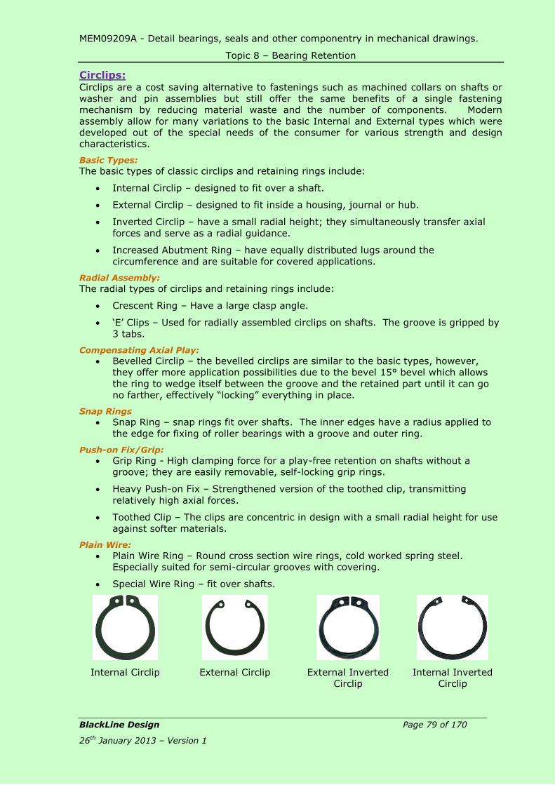
MEM09209A - Detail bearings, seals and other componentry in mechanical drawings.
Topic 8 – Bearing Retention
BlackLine Design Page 79 of 170
26th January 2013 – Version 1
Circlips: Circlips are a cost saving alternative to fastenings such as machined collars on shafts or
washer and pin assemblies but still offer the same benefits of a single fastening
mechanism by reducing material waste and the number of components. Modern
assembly allow for many variations to the basic Internal and External types which were
developed out of the special needs of the consumer for various strength and design
characteristics.
Basic Types:
The basic types of classic circlips and retaining rings include:
Internal Circlip – designed to fit over a shaft.
External Circlip – designed to fit inside a housing, journal or hub.
Inverted Circlip – have a small radial height; they simultaneously transfer axial
forces and serve as a radial guidance.
Increased Abutment Ring – have equally distributed lugs around the
circumference and are suitable for covered applications.
Radial Assembly:
The radial types of circlips and retaining rings include:
Crescent Ring – Have a large clasp angle.
‘E’ Clips – Used for radially assembled circlips on shafts. The groove is gripped by
3 tabs.
Compensating Axial Play:
Bevelled Circlip – the bevelled circlips are similar to the basic types, however,
they offer more application possibilities due to the bevel 15° bevel which allows
the ring to wedge itself between the groove and the retained part until it can go
no farther, effectively “locking” everything in place.
Snap Rings
Snap Ring – snap rings fit over shafts. The inner edges have a radius applied to
the edge for fixing of roller bearings with a groove and outer ring.
Push-on Fix/Grip:
Grip Ring - High clamping force for a play-free retention on shafts without a
groove; they are easily removable, self-locking grip rings.
Heavy Push-on Fix – Strengthened version of the toothed clip, transmitting
relatively high axial forces.
Toothed Clip – The clips are concentric in design with a small radial height for use
against softer materials.
Plain Wire:
Plain Wire Ring – Round cross section wire rings, cold worked spring steel.
Especially suited for semi-circular grooves with covering.
Special Wire Ring – fit over shafts.
Internal Circlip External Circlip External Inverted
Circlip
Internal Inverted
Circlip

MEM09209A - Detail bearings, seals and other componentry in mechanical drawings.
Topic 8 – Bearing Retention
BlackLine Design Page 80 of 170
26th January 2013 – Version 1
External Increased
Abutment Ring
Internal Increased
Abutment Ring
Crescent Ring E-Clip
Bevelled Circlip Snap Ring Grip Ring Heavy Duty Push-
on Fix
Toothed Clip Plain Wire Ring Special Wire Rings
All circlips are inserted
and removed using
special long-nosed
pliers
Display of Circlips on an Assembly Drawing:
As most circlips are very narrow with
respect to the shaft diameter, and hidden
line will display as a continuous line in the
view. All circlips can be solid filled so they
are readily identifiable on a drawing.
Circlips are not included on a detail
drawing, only the grooves.
Figure 8.10

MEM09209A - Detail bearings, seals and other componentry in mechanical drawings.
Topic 8 – Bearing Retention
BlackLine Design Page 81 of 170
26th January 2013 – Version 1
Circlip Grooves:
The dimensions for each circlip groove must be
shaft or bore diameter. Tables Table 1 – Internal Circlips is used to determine the groves for shafts while Table 2 –
External Circlips. The dimension in each column correlates to the lettered dimensi9on in
the diagrams shown in Figure 8.11 for Internal Circlips and Figure 8.12 for External
Circlips.
The same method is used for reading the two tables in determining the required
dimensions.
Figure 8.11
Figure 8.12
Example 10-1:
Create a detail of a circlip groove to suit a Ø108 housing.
Procedure:
Study Figure 8.11 to determine the data required
Refer to Tables Table 1 – Internal Circlips to determine the sizes.
Figure 8.11 shows the dimensions required are ‘B’ for the groove diameter, ‘W’ for
the groove width, ‘b’ for the thickness of the circlip.
Refer to the Tables

MEM09209A - Detail bearings, seals and other componentry in mechanical drawings.
Topic 8 – Bearing Retention
BlackLine Design Page 82 of 170
26th January 2013 – Version 1
Table 1 – Internal Circlips and look down the first column labelled Bore B until the
size 108 is displayed.
Read across the row and note dimension ‘G’ is
112, ‘W’ is 4.15 and ‘b’ is 8.9.
The groove can now be drawn on the assembly
or detail drawing.
When producing the detail drawing, applicable
tolerances can be applied as required.

MEM09209A - Detail bearings, seals and other componentry in mechanical drawings.
Topic 8 – Bearing Retention
BlackLine Design Page 83 of 170
26th January 2013 – Version 1
Skill Practice Exercises:
Skill Practice Exercise: MEM09209-SP-0801
1. Create a new drawing using the template called Gear Housing located on the
network drive. Complete the assembly by adding the bearings, circlips and
completing the shaft and housing where shown.
2. Use the Tables to determine the size of each circlip groove.
3. Produce an assembly drawing of the Gear Housing including a parts list and cross
referencing.
4. Create detail drawings of the Housing and the Shaft applying toleranced
dimensions to suit S7-h6 fits between the Housing, Shaft and bearings. One of the
views is to include a full or half sectional view along the cutting plane
5. All cylindrical surfaces for the bearings are to be reamed to a finish of 0.2, be
concentric to the datum centreline to 0.025 and roundness to 0.05.
6. All straight mating surfaces are to be milled to 0.4 and perpendicular to the
centreline to 0.1.
7. Provide appropriate normal fitting 60 mm long keys to both ends of the shaft.
8. Insert an A3 sheet on both drawings and save the drawing in your work area as
MEM09209-SP-0801 before plotting the finished drawings.
The Housing is circular in shape. All toleranced dimensions are to be placed on the
drawing as Limit of Size.
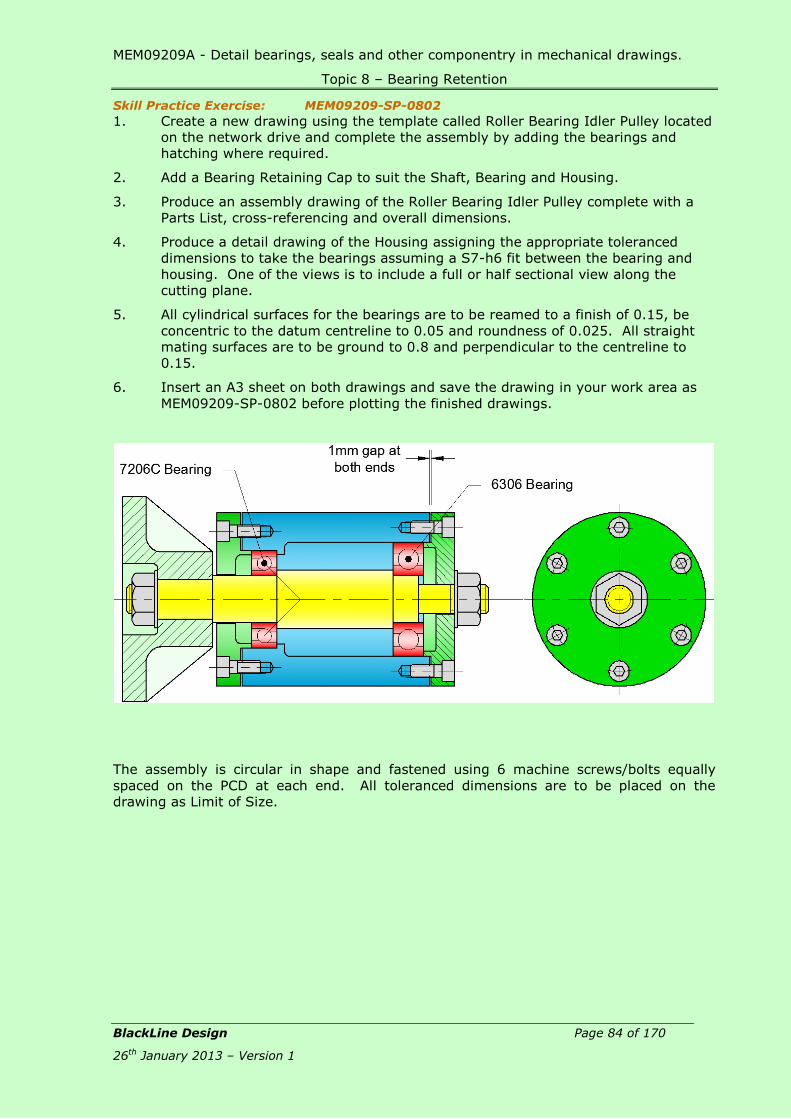
MEM09209A - Detail bearings, seals and other componentry in mechanical drawings.
Topic 8 – Bearing Retention
BlackLine Design Page 84 of 170
26th January 2013 – Version 1
Skill Practice Exercise: MEM09209-SP-0802
1. Create a new drawing using the template called Roller Bearing Idler Pulley located
on the network drive and complete the assembly by adding the bearings and
hatching where required.
2. Add a Bearing Retaining Cap to suit the Shaft, Bearing and Housing.
3. Produce an assembly drawing of the Roller Bearing Idler Pulley complete with a
Parts List, cross-referencing and overall dimensions.
4. Produce a detail drawing of the Housing assigning the appropriate toleranced
dimensions to take the bearings assuming a S7-h6 fit between the bearing and
housing. One of the views is to include a full or half sectional view along the
cutting plane.
5. All cylindrical surfaces for the bearings are to be reamed to a finish of 0.15, be
concentric to the datum centreline to 0.05 and roundness of 0.025. All straight
mating surfaces are to be ground to 0.8 and perpendicular to the centreline to
0.15.
6. Insert an A3 sheet on both drawings and save the drawing in your work area as
MEM09209-SP-0802 before plotting the finished drawings.
The assembly is circular in shape and fastened using 6 machine screws/bolts equally
spaced on the PCD at each end. All toleranced dimensions are to be placed on the
drawing as Limit of Size.

MEM09209A - Detail bearings, seals and other componentry in mechanical drawings.
Topic 9 – O-Rings
BlackLine Design Page 85 of 170
26th January 2013 – Version 1
Topic 9 – O-Rings:
Required Skills:
Produce an assembly drawing and indicate O-rings using the correct symbols.
Produce a detail drawing of engineering components containing grooves for O-
rings.
Required Knowledge:
Purpose for using seals in engineering applications.
Conditions for using O-rings in engineering applications.
Use tables to determine dimensions for detailing O-ring grooves.
Application of toleranced dimensions.
Seals: O-Rings: The “O” ring is the simplest form of seals. It is a synthetic rubber ring of solid circular
cross-section and made in a wide variety of ring and cross-section diameters. “O” rings
are suitable for static sealing e.g., pipe joints, cylinder end covers and valve spindles.
Although designed primarily for static situations, O-rings can be used for low speed
dynamic sealing of pistons and piston rods in hydraulic and pneumatic cylinders.
O-ring seals fall into 2 application categories; Static and Dynamic. Static seals exist
when there is no relative motion between the mating surfaces being sealed. Dynamic
Seals function in an environment where the mating surfaces are in reciprocating
(alternating direction of motion), rotary (turning) or oscillating (vibrating) motion to each
other. Static seals can sustain greater range of tolerances, rougher surface finishes and
higher pressure limits. The types of static O-ring seals are: Static Radial Seal, Static
Axial (Face) Seal, Static Seals with Dovetail Grooves, Static Crush Seals and Straight
Thread Fitting Seals.
All grooves for O-Rings can be determined using Table 16 – O-Rings.
Static Seals:
Static seals exist where there is no relative motion between the mating surfaces being
sealed. There are four types of static seals; Static Radial, Static Axial, Dovetail Grooves
and Crush.
Static Radial Seal
Static radial seals are formed when squeeze (compression) is applied to the inside
diameter (I.D.) and outside diameter (O.D.) of the O-ring. Cap and plug type
configurations commonly utilize radial seals. An example of a static radial O-ring seal
for a male gland is shown in Figure 9.1 while a static radial O-ring seal for a female gland
is shown in Figure 9.2.
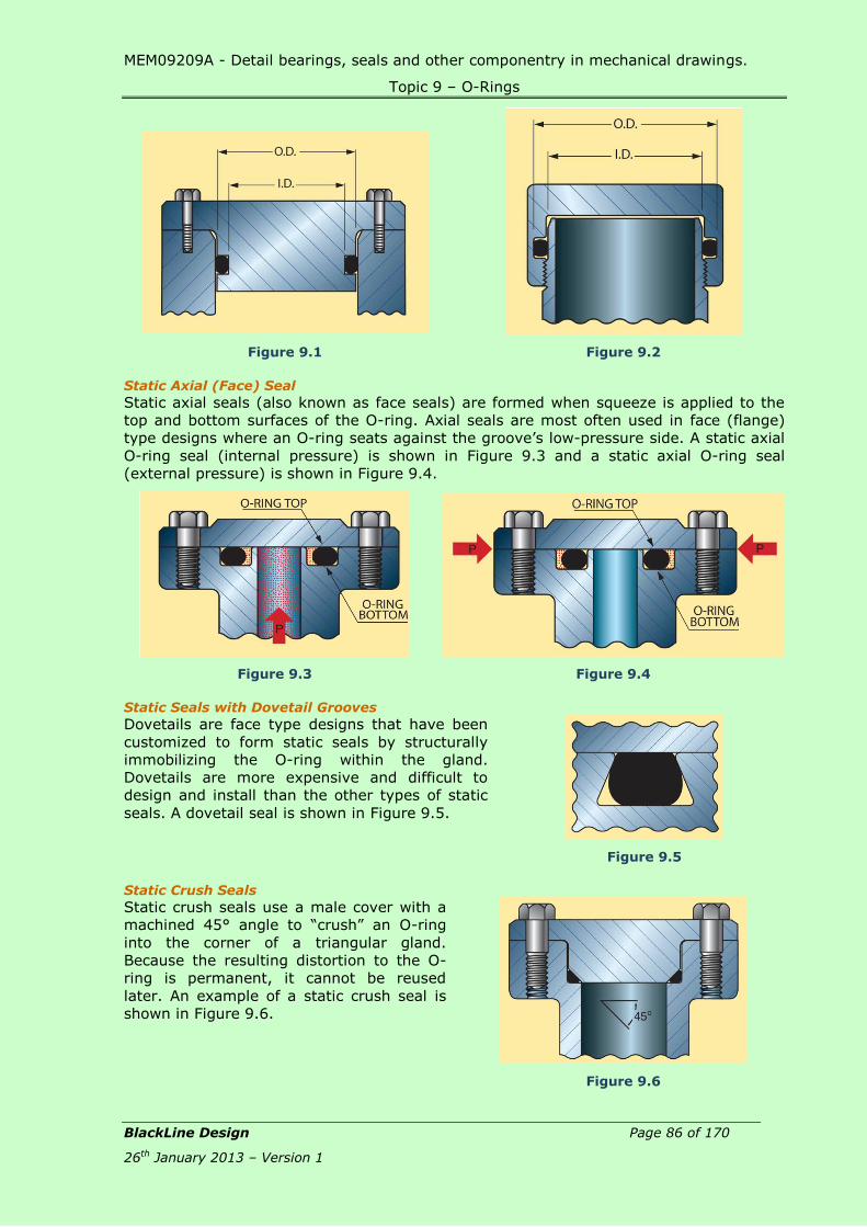
MEM09209A - Detail bearings, seals and other componentry in mechanical drawings.
Topic 9 – O-Rings
BlackLine Design Page 86 of 170
26th January 2013 – Version 1
Figure 9.1
Figure 9.2
Static Axial (Face) Seal
Static axial seals (also known as face seals) are formed when squeeze is applied to the
top and bottom surfaces of the O-ring. Axial seals are most often used in face (flange)
type designs where an O-ring seats against the groove’s low-pressure side. A static axial
O-ring seal (internal pressure) is shown in Figure 9.3 and a static axial O-ring seal
(external pressure) is shown in Figure 9.4.
Figure 9.3
Figure 9.4
Static Seals with Dovetail Grooves
Dovetails are face type designs that have been
customized to form static seals by structurally
immobilizing the O-ring within the gland.
Dovetails are more expensive and difficult to
design and install than the other types of static
seals. A dovetail seal is shown in Figure 9.5.
Figure 9.5
Static Crush Seals
Static crush seals use a male cover with a
machined 45° angle to “crush” an O-ring
into the corner of a triangular gland.
Because the resulting distortion to the O-
ring is permanent, it cannot be reused
later. An example of a static crush seal is
shown in Figure 9.6.
Figure 9.6

MEM09209A - Detail bearings, seals and other componentry in mechanical drawings.
Topic 9 – O-Rings
BlackLine Design Page 87 of 170
26th January 2013 – Version 1
Dynamic Seals:
In contrast to static seals, dynamic seals exist where there is relative motion between
the mating surfaces being sealed. In most instances, the dimensional variations
inherent in dynamic seals make them more difficult to design and more expensive to
construct than static seals. Nevertheless, dynamic O-ring seals are indispensable to a
wide variety of applications.
Reciprocating Seals:
Reciprocating seals involve relative reciprocating motion along the shaft axis between the
inner and outer elements. In reciprocating seal applications, the O-ring slides or rocks
back and forth within its gland with the reciprocating motion.
Reciprocating seals are most often seen in cylinders and linear actuators. Some
examples of reciprocating O-ring seals are shown in Figure 9.7 and Figure 9.8.
Figure 9.7
Figure 9.8
Floating Pneumatic Piston Seals:
Floating pneumatic piston seals are reciprocating in nature, but the way in which the
seals are affected is unique. Normal reciprocating designs rely on the O-ring being
stretched over a piston and then squeezed radially (on the inside diameter, or I.D., and
the outside diameter, or O.D.).
In floating O-ring designs, however, there is no radial squeeze on the seal’s cross-
section. The O-ring’s O.D. is larger than the cylinder bore diameter. Peripheral squeeze
is applied to the O.D. as the O-ring is installed into the bore. Incoming air pressure
forces the O-ring against the groove wall, and a seal is affected as shown in Figure 9.9.
Floating designs offer a number
of advantages, including greatly
reduced breakout friction and
longer seal life. Floating
pneumatic piston seals are suited
for applications in which the air
pressure does not exceed 29 kPa.
Floating O-rings are NOT suitable
as rod seals.
Figure 9.9
Rotary Seals:
Rotary seals involve motion between a shaft and housing. Typical rotary seals include
motor shafts and wheels on a fixed axle. Installation of a rotary O-ring seal is shown in
Figure 9.10. Most manufacturers recommend lip type shaft seals for most rotary
applications; several applications can exist where an O-ring will provide an effective
rotary seal.

MEM09209A - Detail bearings, seals and other componentry in mechanical drawings.
Topic 9 – O-Rings
BlackLine Design Page 88 of 170
26th January 2013 – Version 1
O-ring seals are NOT recommended for rotary applications under the following
conditions:
Pressures exceeding 116 kPa.
Temperatures lower than -40° C (-40° F) or higher than 107° C (225° F).
Surface speeds exceeding 180 meters per minute.
When an elastomer is stretched and heated, it will contract; this is called the Gough-
Joule effect and is an important design consideration in a rotary application because if an
O-ring is installed in a stretched condition, frictional heat will cause the O-ring to contract
onto the shaft and may cause the O-ring to seize the rotating shaft so that the dynamic
interface becomes the O-ring O.D. and the groove I.D.; the contraction will also cause
more frictional heat, further exacerbating the situation and causing premature failure of
the O-ring.
Most rotary O-ring seals are designed so that the free O-ring I.D. is larger than the shaft
onto which it fits. The gland I.D. is smaller than the free O-ring O.D. so that when it is
placed into the gland, the O-ring is peripherally squeezed, and the I.D. is reduced so that
a positive interference exists between the O-ring I.D. and the shaft. Because the O-ring
is not in a stretched condition, it will not build up heat, seize the shaft, and rotate in the
groove.
Rotary seals (such as the one shown in Figure 9.11) do not dissipate heat as well as
reciprocating seals do, so provisions must be made to keep heat build-up to a minimum.
The housing I.D. should not be used as a bearing surface.
Bearings should be provided to ensure that the shaft runout does not
exceed 0.05 mm TIR.
The O-ring groove should be located away from the bearing and close to
the lubricating fluid.
The housing length should be 8 to 10 times the O-ring cross-section to
provide for better heat transfer.
To prevent extrusion of the O-ring, the clearance gap (extrusion gap) should not be more
than 0.125 mm per side. If pressures greater than 116kPa are encountered, it is
recommended that an 80 durometre O-ring be used.
The minimum hardness for the section of shaft that comes into contact with the O-rings
is Rockwell C30. To prevent excessive wear, scratches, nicks, and handling damage, a
hardness of Rockwell C45 is recommended. A shaft finish of 0.01 mm to 0.02 mm is
recommended, and plunge grinding with no machine lead is the preferred finishing
method. The shaft ends should be chamfered with a 15/30° chamfer to prevent
installation damage.
Figure 9.10
Figure 9.11

MEM09209A - Detail bearings, seals and other componentry in mechanical drawings.
Topic 9 – O-Rings
BlackLine Design Page 89 of 170
26th January 2013 – Version 1
Oscillating Seals:
Oscillating seals are commonly used in
faucet valves. In oscillating applications,
the shaft or housing rotates back and forth
through a limited number of turns around
the axis of the shaft. An oscillating O-ring
seal is shown in Figure 9.12.
Figure 9.12
Other Cross Sectional Options: Although O-rings are ideal for a wide variety of applications, they are not suitable for all
situations.
Lobed Seals (X-rings)
Lobed seals are also known as X-rings and have the
advantage of doubling the number of sealing surfaces
found on the traditional O-rings. Lobed seals require less
compression than O-rings which make them suitable for
the use in dynamic situations. Due to their design, lobed
seals provide improved sealing ability and are more
resistant to twisting.
Square Rings
Square rings are circular sealing devices that utilize a square
rather than circular cross-section. Square rings do not seal
as well as O-rings because the circular cross-section allows
for more concentrated loading.
U-Cups
U-cups can be used in static and dynamic applications. Due
to the pressure-actuated lip they operate with lower break-
out () and running friction. U-cups can be used in a dynamic
application, however they are unidirectional and 2 seals are
required for bidirectional sealing.
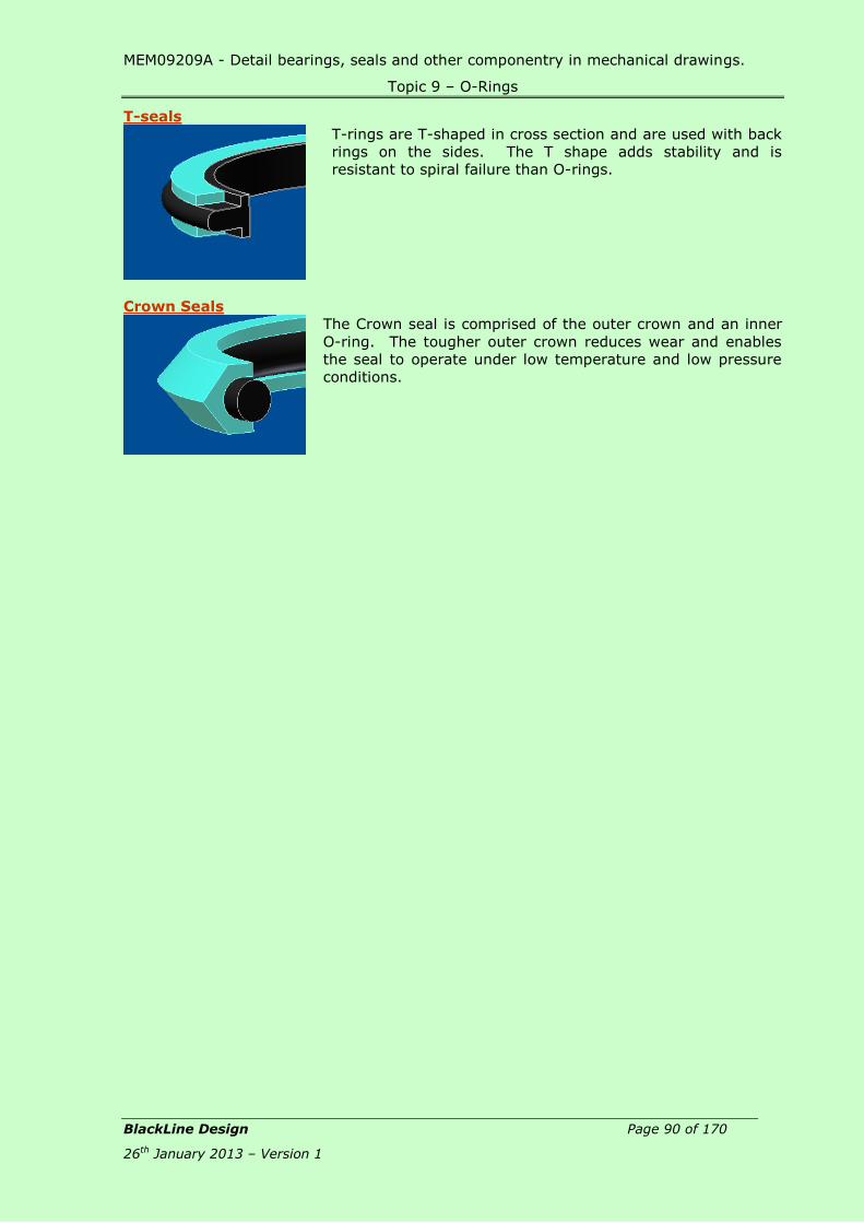
MEM09209A - Detail bearings, seals and other componentry in mechanical drawings.
Topic 9 – O-Rings
BlackLine Design Page 90 of 170
26th January 2013 – Version 1
T-seals
T-rings are T-shaped in cross section and are used with back
rings on the sides. The T shape adds stability and is
resistant to spiral failure than O-rings.
Crown Seals
The Crown seal is comprised of the outer crown and an inner
O-ring. The tougher outer crown reduces wear and enables
the seal to operate under low temperature and low pressure
conditions.

MEM09209A - Detail bearings, seals and other componentry in mechanical drawings.
Topic 9 – O-Rings
BlackLine Design Page 91 of 170
26th January 2013 – Version 1
Skill Practice Exercises
Skill Practice Exercise: MEM09209-SP-0901
1. Using the template file provided on the network drive called Hydraulic Actuator,
complete the assembly by adding grooves for O-Rings where indicated.
2. Produce an assembly drawing of the Hydraulic Actuator including a Parts List and
cross-referencing.
3. Produce detail drawings of the Piston, Housing, End Caps and Piston Seal Ring
assigning details for the O-Ring grooves. One of the views is to include a full or half
sectional view along the cutting plane.
4. Assign Limit of Size dimensions a G7/h6 fit between mating surfaces.
5. Indicate that all mating surfaces are to be bored or machined to a roughness of 0.2.
All circular features are to be concentric to the centreline while all vertical surfaces
are perpendicular to the centreline to 0.05.
6. Save the completed drawing as MEM09209-SP-0901.
7. End Caps, Housing, Piston and Piston Seal Ring can be considered to be circular in
shape.
The assembly can be considered circular in shape and fastened using 4 machine
screws/bolts equally spaced on the PCD at each end offset at 45° to the centreline. All
toleranced dimensions are to be placed on the drawing as Limit of Size.
Material: End Caps – Aluminium Alloy; Housing – Aluminium Alloy; Shaft – Mild
Steel; Piston Seal Ring – Nylon; Fasteners – Commercial; O-Rings – Rubber.
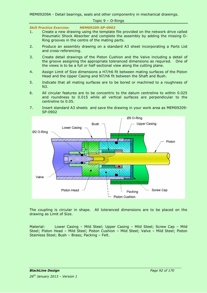
MEM09209A - Detail bearings, seals and other componentry in mechanical drawings.
Topic 9 – O-Rings
BlackLine Design Page 92 of 170
26th January 2013 – Version 1
Skill Practice Exercise: MEM09209-SP-0902
1. Create a new drawing using the template file provided on the network drive called
Pneumatic Shock Absorber and complete the assembly by adding the missing O-
Ring grooves in the centre of the mating parts.
2. Produce an assembly drawing on a standard A3 sheet incorporating a Parts List
and cross-referencing.
3. Create detail drawings of the Piston Cushion and the Valve including a detail of
the groove assigning the appropriate toleranced dimensions as required. One of
the views is to be a full or half sectional view along the cutting plane.
4. Assign Limit of Size dimensions a H7/h6 fit between mating surfaces of the Piston
Head and the Upper Casing and N7/h6 fit between the Shaft and Bush.
5. Indicate that all mating surfaces are to be bored or machined to a roughness of
N3.
6. All circular features are to be concentric to the datum centreline to within 0.025
and roundness to 0.015 while all vertical surfaces are perpendicular to the
centreline to 0.05.
7. Insert standard A3 sheets and save the drawing in your work area as MEM09209-
SP-0902
The coupling is circular in shape. All toleranced dimensions are to be placed on the
drawing as Limit of Size.
Material: Lower Casing – Mild Steel; Upper Casing – Mild Steel; Screw Cap – Mild
Steel; Piston Head – Mild Steel; Piston Cushion – Mild Steel; Valve – Mild Steel; Piston
Stainless Steel; Bush – Brass; Packing – Felt.

MEM09209A - Detail bearings, seals and other componentry in mechanical drawings.
Topic 10 – Engineering Seals
BlackLine Design Page 93 of 170
26th January 2013 – Version 1
Topic 10 – Seals:
Required Skills:
Produce an assembly drawing and indicate the appropriate seal using the
correct symbols.
Use manufacturer’s charts, specifications and catalogues to determine the
sizes of seal grooves.
Required Knowledge:
Purpose of different mechanical seals.
The names of various mechanical seals.
Materials used in the production of mechanical seals.
Advantages and disadvantages of the various mechanical seals.
Application of toleranced dimensions.
Seals: Seals are used as the name implies, to prevent lubricants from leaking out, or through
bearings, or to prevent foreign particles, dust, grit, and corrosive liquids including water
from getting onto the surface of the bearing or mixing with the lubricant. In the case of
anti-friction bearings, ALL foreign matter causes a rapid breakdown of the balls, rollers
and raceways. Seals are made in various designs and of different materials, depending
on the type of service required as shown in Figure 10.1.
Figure 10.1
Factors to consider are:
Impervious to the type of lubricant used.
Temperature of operation.
Frictional wear.
Resistance to chemical or acid solutions with which it may come in contact.
Types of Seals:
Felt Seal:
Felt seals consist of a felt material encased in a steel shell. Felt seals are used in light
applications to exclude dust and grit, and can be used at shaft speeds of 305 m/sec and
temperatures to 49°C. Felt is a built up fabric made by interlocking fibres through a
suitable combination of mechanical work, chemical action, moisture and heat without
spinning, weaving or knitting. It may consist of one or more classes of fibres – wool,
reprocessed wool, or reused wool – which are used alone or combined with animal,
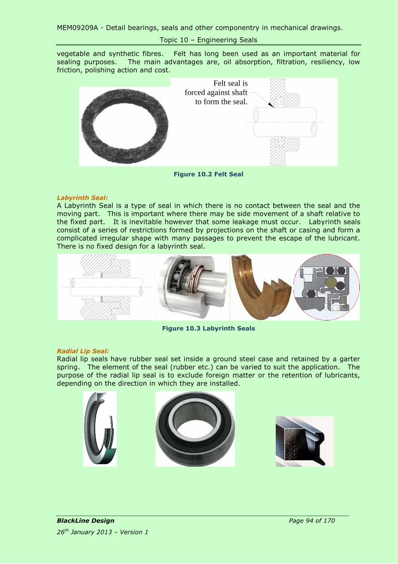
MEM09209A - Detail bearings, seals and other componentry in mechanical drawings.
Topic 10 – Engineering Seals
BlackLine Design Page 94 of 170
26th January 2013 – Version 1
vegetable and synthetic fibres. Felt has long been used as an important material for
sealing purposes. The main advantages are, oil absorption, filtration, resiliency, low
friction, polishing action and cost.
Figure 10.2 Felt Seal
Labyrinth Seal:
A Labyrinth Seal is a type of seal in which there is no contact between the seal and the
moving part. This is important where there may be side movement of a shaft relative to
the fixed part. It is inevitable however that some leakage must occur. Labyrinth seals
consist of a series of restrictions formed by projections on the shaft or casing and form a
complicated irregular shape with many passages to prevent the escape of the lubricant.
There is no fixed design for a labyrinth seal.
Figure 10.3 Labyrinth Seals
Radial Lip Seal:
Radial lip seals have rubber seal set inside a ground steel case and retained by a garter
spring. The element of the seal (rubber etc.) can be varied to suit the application. The
purpose of the radial lip seal is to exclude foreign matter or the retention of lubricants,
depending on the direction in which they are installed.
Felt seal is
forced against shaft
to form the seal.

MEM09209A - Detail bearings, seals and other componentry in mechanical drawings.
Topic 10 – Engineering Seals
BlackLine Design Page 95 of 170
26th January 2013 – Version 1
Figure 10.4 Radial Lip Seal
Rod Wiper Seal:
Contamination particles in the hydraulic system are the most common cause for
breakdowns and short service life of seals. A majority of the contaminating particles
reaches the system on the rod; the wiper seal's task is to prevent this.
The wiper seal is the most undervalued seal type in the hydraulic cylinder in relation to
its important function. The choice of wiper seal should, however, be founded on as
carefully drawn-up requirement specifications as the choice of piston and rod seals. The
surrounding environment and service conditions must be taken into special consideration.
The wiper seal must be designed not only to fit the rod (dynamic function) but also to
seal in the housing (static function).
Figure 10.5 Rod Wiper Seals
Rod Seal:
The rod seal is the seal in the hydraulic cylinder with the most demanding requirement
specifications. In addition to normal wear and aging, this seal is directly affected by
changes on the rod’s surface.
The rod seal is often the decisive factor for
the function of the hydraulic cylinder in its
entirety. Leakage through the rod seal can
in some cases cause accidents and
environmental damages; therefore, it is of
significant importance to make the correct
choice of rod seal and not the least, to be
familiar with the properties of other
existing seal types.
Figure 10.6 Rod Seal
Piston Seal:
The basic demand on piston seals as well as on rod seals for hydraulic cylinders under
the operating conditions for which they have been chosen, is to maintain a high level of

MEM09209A - Detail bearings, seals and other componentry in mechanical drawings.
Topic 10 – Engineering Seals
BlackLine Design Page 96 of 170
26th January 2013 – Version 1
sealing performance during their service life. The overall demands on both these
function-determining main seals in the hydraulic cylinder are meanwhile very different in
many respects. In this section, we feature both single- and double-acting piston seals.
The choice of the type of piston seal is to a great extent decided by the way in which the
cylinder operates. For a cylinder which is exclusively single-acting, it is always best to
choose the type of seal designed to provide optimum sealing qualities for single-acting
functions, with, for instance, the thinnest possible lubrication film that can pass through
the contact area between the seal and the cylinder tube surface.
The best sealing capacity of a double-acting cylinder
is achieved by choosing a double-acting seal. A
piston design where two single-acting seals on the
piston for a double-acting cylinder are used can
easily give rise to a breakdown. The reason is that a
very high pressure can be trapped between the
seals.
Piston seals, both single- and double-acting, can be
designed for and used with integrated or separate
back-up rings and guide rings. The ultimate choice
must be based on the operating conditions of the
cylinder.
Figure 10.7 Piston Seal
Guide Rings and Strips:
The task of guide rings and guide strips of plastic materials is to guide the piston in the
cylinder bore and the rod in the cylinder head in a working hydraulic cylinder as well as
to withstand arising side loads and prevent metallic contact between these axially mobile
parts. Plastic guides have been used instead of metallic guides for several years now
which has resulted in a considerably longer service life for hydraulic cylinders. Plastic
materials work more smoothly against the cylinder tube and the sealing surface of the
rod, although contamination particles often are included in the hydraulic oil.
Metal guides are only slightly deformed
also at heavy loads which imply that the
force is concentrated to small areas. The
speed in a hydraulic cylinder is also very
low from a guide function point of view
which results in an insufficient lubrication;
this condition in combination with the
presence of contamination particles result
in a rapid wear of the metal guide, the
cylinder tube and the rod surface.
Figure 10.8
Split Ring Seal:
Split rings are used for a large number of seal applications. Expanding split rings (piston
rings) are used in compressors, pumps and internal combustion engines. Applications
for straight cut and seal joint rings are common in industrial and aerospace hydraulic and
pneumatic cylinders (linear actuators) where the ruggedness of piston rings is
advantageous and where various degrees of leakage can be tolerated. The rings are
made of cast iron or steel, are rectangular in cross-section and fit into grooves of the
same shape in the piston. The ring is cut so that it springs out against the cylinder wall
to ensure a good seal. A typical petrol engine piston has two compression rings for gas
sealing and an oil scraper ring that prevents oil from entering the combustion chamber.
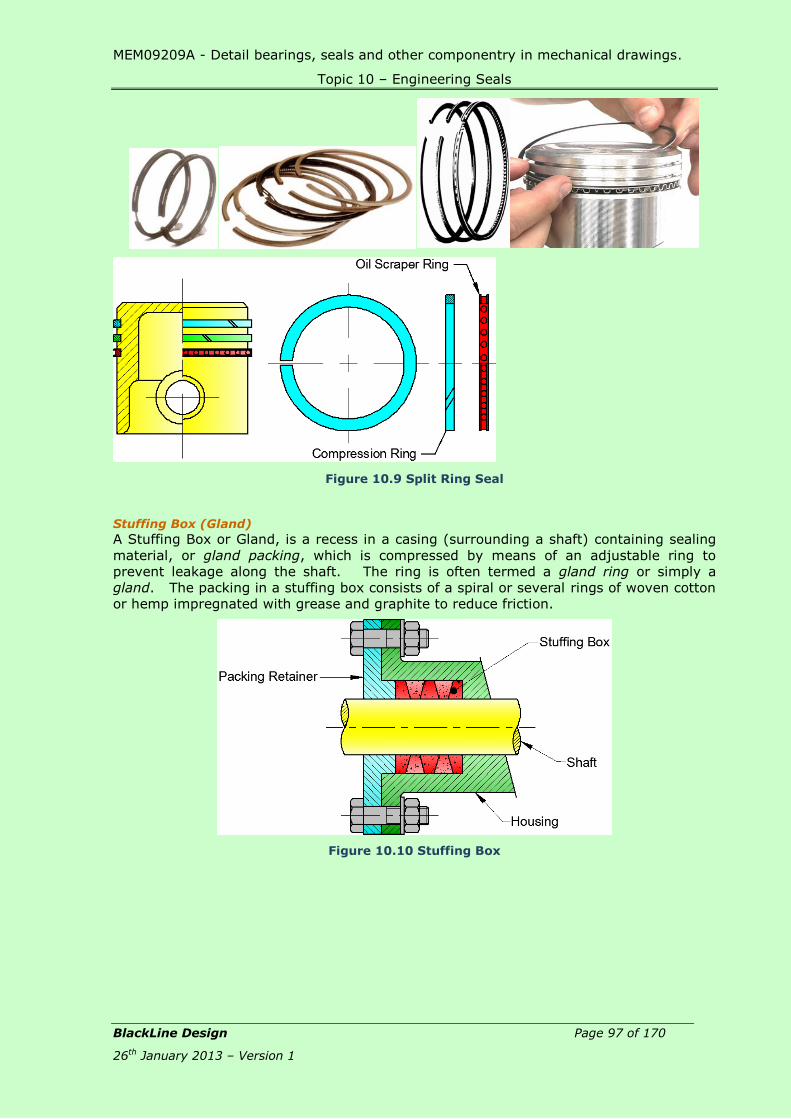
MEM09209A - Detail bearings, seals and other componentry in mechanical drawings.
Topic 10 – Engineering Seals
BlackLine Design Page 97 of 170
26th January 2013 – Version 1
Figure 10.9 Split Ring Seal
Stuffing Box (Gland)
A Stuffing Box or Gland, is a recess in a casing (surrounding a shaft) containing sealing
material, or gland packing, which is compressed by means of an adjustable ring to
prevent leakage along the shaft. The ring is often termed a gland ring or simply a
gland. The packing in a stuffing box consists of a spiral or several rings of woven cotton
or hemp impregnated with grease and graphite to reduce friction.
Figure 10.10 Stuffing Box
MEM09209A - Detail bearings, seals and other componentry in mechanical drawings.
Topic 10 – Engineering Seals
BlackLine Design Page 98 of 170
26th January 2013 – Version 1
Seal Materials:
Seal Face:
Bronze, Carbon, Glass Filled PTFE, Moulded Plastic and Tungsten Carbide.
Casing:
Bronze, Brass, Monel, Chrome Steel and Stainless Steel
Elastomers:
A range of many various polymers having the elastic properties of natural
rubber including Buna, Viton ®, Neoprene, Teflon® and Asbestos.
Seal Seats:
Bronze, Cast Iron, Ceramic, Silicon Carbide and Tungsten Carbide.
Springs:
Monel, Stainless Steel and Spring Steel.
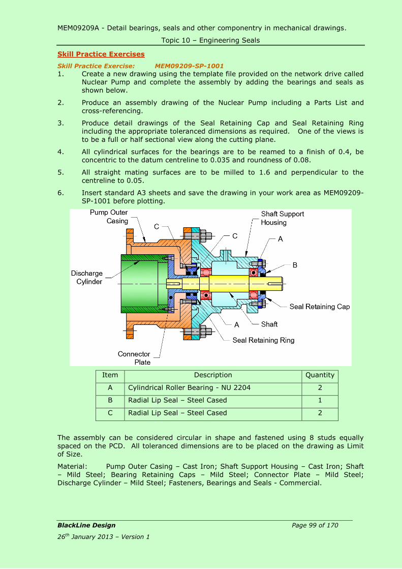
MEM09209A - Detail bearings, seals and other componentry in mechanical drawings.
Topic 10 – Engineering Seals
BlackLine Design Page 99 of 170
26th January 2013 – Version 1
Skill Practice Exercises
Skill Practice Exercise: MEM09209-SP-1001
1. Create a new drawing using the template file provided on the network drive called
Nuclear Pump and complete the assembly by adding the bearings and seals as
shown below.
2. Produce an assembly drawing of the Nuclear Pump including a Parts List and
cross-referencing.
3. Produce detail drawings of the Seal Retaining Cap and Seal Retaining Ring
including the appropriate toleranced dimensions as required. One of the views is
to be a full or half sectional view along the cutting plane.
4. All cylindrical surfaces for the bearings are to be reamed to a finish of 0.4, be
concentric to the datum centreline to 0.035 and roundness of 0.08.
5. All straight mating surfaces are to be milled to 1.6 and perpendicular to the
centreline to 0.05.
6. Insert standard A3 sheets and save the drawing in your work area as MEM09209-
SP-1001 before plotting.
Item Description Quantity
A Cylindrical Roller Bearing - NU 2204 2
B Radial Lip Seal – Steel Cased 1
C Radial Lip Seal – Steel Cased 2
The assembly can be considered circular in shape and fastened using 8 studs equally
spaced on the PCD. All toleranced dimensions are to be placed on the drawing as Limit
of Size.
Material: Pump Outer Casing – Cast Iron; Shaft Support Housing – Cast Iron; Shaft
– Mild Steel; Bearing Retaining Caps – Mild Steel; Connector Plate – Mild Steel;
Discharge Cylinder – Mild Steel; Fasteners, Bearings and Seals - Commercial.

MEM09209A - Detail bearings, seals and other componentry in mechanical drawings.
Topic 10 – Engineering Seals
BlackLine Design Page 100 of 170
26th January 2013 – Version 1
Skill Practice Exercise: MEM09209-SP-1002
1. Create a new drawing using the template file provided on the network drive called
Shock Absorber and complete the assembly by adding the seals as shown below.
2. Produce an assembly drawing of the Shock Absorber including a Parts List and
cross-referencing.
3. Produce detail drawings of the End Piston and Reciprocator including the
appropriate toleranced dimensions as required. One of the views is to be a full or
half sectional view along the cutting plane.
4. All cylindrical surfaces for the bearings are to be reamed to a finish of 0.15, be
concentric to the datum centreline to 0.05 and roundness to 0.8.
5. All flat mating surfaces are to be milled to 0.8 and perpendicular to the centreline
to 0.15 with a flatness of 0.03.
6. Insert standard A3 sheets and save the drawing in your work area as MEM09209-
SP-1002 before plotting.
The assembly can be considered circular. All toleranced dimensions are to be placed on
the drawing as Limit of Size.
Material: Outer Casing – Brass; End Piston – Nylon; Sleeve – Brass; Reciprocator –
Nylon; Spring – Stainless Steel; Piston – Stainless Steel; Shaft – Mild Steel; Piston Cap –
Nylon; Seals – Rubber.

MEM09209A - Detail bearings, seals and other componentry in mechanical drawings.
Topic 11 – Thrust Bearings
BlackLine Design Page 101 of 170
26th January 2013 – Version 1
Topic 11 – Thrust Bearings:
Required Skills: Produce assembly drawings containing thrust bearings.
Produce detail drawings of components requiring thrust bearings.
Required Knowledge:
Identify the symbol and list the applications of the various types of thrust
bearings.
Extract data from trust bearing tables.
Thrust Bearings: A thrust bearing is a type of rotary bearing that permits rotation between parts but are
designed to support high axial (parallel to the shaft) loads. Thrust bearings are available
in the following types: Ball Thrust Bearings, Tapered Roller Bearings, Self-Aligning Thrust
Bearing and Fluid Bearings.
Ball Thrust Bearings:
Ball Thrust Bearings contain balls that are mounted in a cage and run between the faces
of two annular rings, and these may be used to take the weight of a vertical shaft in a
footstep bearing. The object of thrust bearings is to support thrust and axial loads.
The basic single rigid row type has a shallow grooved track in each washer. The load is
taken axially in one direction only and has a limited speed range. The double ball type
will take thrust in both directions
Ball Thrust
Bearing Assembly
Ball Thrust
Bearing
Symbol
Single Direction Thrust Ball Bearings:
A single direction thrust ball bearings consist of a shaft washer, a housing washer and a
ball and cage thrust assembly. The bearings are separable so that mounting is simple as
the washers and the ball and cage assembly can be mounted separately.
Figure 11.1 Figure 11.2 Figure 11.3

MEM09209A - Detail bearings, seals and other componentry in mechanical drawings.
Topic 11 – Thrust Bearings
BlackLine Design Page 102 of 170
26th January 2013 – Version 1
Smaller sizes are available with either a flat seating surface on the housing washer
(Figure 11.1) or a spherical seating surface (Figure 11.2). Bearings with a spherical
housing washer can be used together with a spherical seating washer (Figure 11.3) to
compensate for misalignment between the support surface in the housing and the shaft.
Single direction thrust ball bearings, as their name suggests, can accommodate axial
loads in one direction and thus locate a shaft axially in one direction and must not be
subjected to any radial load.
Double Direction Thrust Ball Bearings:
A double direction thrust ball bearings consist of one shaft washer, two housing washers
and two ball and cage thrust assemblies. The bearings are separable so that mounting is
simple. The various parts can be mounted separately. The housing washers and ball and
cage thrust assemblies are identical to those of the single direction bearings.
Figure 11.4 Figure 11.5 Figure 11.6
Smaller bearings are available with either a flat seating surface on the housing washers
(Figure 11.4) or with a spherical seating surface (Figure 11.5). Bearings with sphered
housing washers can be used together with sphered seating washers (Figure 11.6) to
compensate for misalignment between the housing and shaft. Double direction thrust
ball bearings can accommodate axial loads acting in both directions and can thus serve to
axially locate a shaft in both directions. They must not be subjected to radial load.
Cylindrical Roller Thrust Bearings
Cylindrical roller thrust bearings are suitable for arrangements that have to support
heavy axial loads. Furthermore, they are relatively insensitive to shock loads, are very
stiff and require little axial space. As standard they are available as single direction
bearings and can only accommodate axial loads acting in one direction.
Figure 11.7 Figure 11.8
Cylindrical roller thrust bearings are simple in form and design and are produced in single
row (Figure 11.7) and double row (Figure 11.8) designs. The cylindrical surface of the
rollers is slightly relieved towards the ends. The resulting contact profile virtually
eliminates damaging edge stresses. The bearings are of separable design; the individual
components can be mounted separately.

MEM09209A - Detail bearings, seals and other componentry in mechanical drawings.
Topic 11 – Thrust Bearings
BlackLine Design Page 103 of 170
26th January 2013 – Version 1
Roller Thrust
Bearing Assembly
Roller Thrust
Bearing
Symbol
Taper Roller Thrust Bearings
Taper roller thrust bearings enable axially very compact bearing arrangements to be
produced which can carry very heavy axial loads, are insensitive to shock loads and are
stiff. Manufacturers produce single direction taper roller thrust bearings (Figure 11.9) and
double direction taper roller thrust bearings (Figure 11.10). The screw-down bearings
(Figure 11.11) constitute a special design of single direction taper roller thrust bearing
and have a full complement of rollers. They are used for rolling mill screw-down
arrangements.
Figure 11.9 Figure 11.10 Figure 11.11
Taper roller thrust bearings are produced with the logarithmic contact profile between
raceways and rollers to guarantee optimum stress distribution in the bearing, thus
enhancing bearing life. Taper roller thrust bearings with cage are of separable design so
that the two washers and the roller and cage thrust assembly can be mounted separately
and easily. The full complement screw-down bearings are held together by special
retaining components and, to simplify handling, the washers have threaded holes for eye
bolts.
Taper Roller Thrust
Bearing Assembly
Taper Roller
Thrust Bearing
Symbol

MEM09209A - Detail bearings, seals and other componentry in mechanical drawings.
Topic 11 – Thrust Bearings
BlackLine Design Page 104 of 170
26th January 2013 – Version 1
Spherical Roller Thrust Bearings
In spherical roller thrust bearings the load is transmitted from one raceway to the other
at an angle to the bearing axis (Figure 11.12). The bearings are therefore suitable to
accommodate radial loads in addition to simultaneously acting axial loads. Another
important characteristic of spherical roller thrust bearings is their self-aligning capability.
This makes the bearings insensitive to shaft deflection and misalignment of the shaft
relative to the housing.
Figure 11.12 Figure 11.13 Figure 11.14
Spherical roller thrust bearings incorporate a large number of asymmetrical rollers and
have specially designed raceways with an optimum conformity. They can therefore
support very heavy axial loads and permit relatively high speed operation. Spherical
roller thrust bearings are produced in two designs depending on the size and series.
Bearings up to and including size 68 identified by the designation suffix E have a pressed
steel window-type cage which, with the rollers, forms a non-separable assembly with the
shaft washer (Figure 11.13). All other bearings have a machined brass or steel cage
which is guided by a sleeve held in the shaft washer bore (Figure 11.14). The shaft
washer and cage with rollers form a non-separable unit.
Spherical Roller
Thrust Bearing
Assembly
Spherical Roller
Thrust Bearing
Symbol
Needle Roller Thrust Bearings Thrust Bearing
Needle roller thrust bearings can support heavy axial loads, are insensitive to shock loads
and provide stiff bearing arrangements which require a minimum of axial space. They are
single direction bearings and can only accommodate axial loads acting in one direction.
Particularly compact bearing arrangements can be made, taking up no more space than a
conventional thrust washer, if the faces of adjacent machine components can serve as
raceways for a needle roller and cage thrust assembly. For applications where adjacent
components cannot serve as raceways, the assemblies can also be combined with
washers of various designs.
Because of all the possible combinations, all bearing components must be ordered
separately.

MEM09209A - Detail bearings, seals and other componentry in mechanical drawings.
Topic 11 – Thrust Bearings
BlackLine Design Page 105 of 170
26th January 2013 – Version 1
Angular Contact Thrust Bearing
The Angular contact thrust ball bearings were originally designed to support the rotary
tables of drilling rigs but are also suitable for other applications where high load carrying
capacity, high axial stiffness and low friction torque are important. In contrast to
conventional thrust ball bearings, angular contact thrust ball bearings can accommodate
radial loads in addition to axial loads and are able to operate at high speeds.
Figure 11.15 Figure 11.16
Single Direction Angular Contact Thrust Ball Bearings
Single direction angular contact ball bearings (Figure 11.15) are able to take up axial
loads acting in one direction. They are of separable design, i.e. the washers and ball and
cage assembly can be mounted individually. In the main application area for these
bearings – rotary tables – two bearings are always adjusted against each other. The
second bearing has to carry the weight of the drill when it is stationary and has a higher
load carrying capacity than the first bearing.
Double Direction Angular Contact Thrust Ball Bearings
In bearings of the double direction design (Figure 11.16), the upper bearing with the
higher load carrying capacity and the smaller bearing which locates in the opposite
direction are combined together to form a unit. These bearings have low height and can
accommodate axial loads acting in both directions as well as moment loads. A single
bearing can therefore be used to support rotating machine components in relation to
stationary components. These double direction bearings are also of separable design.
Fluid Thrust Bearing:
Fluid thrust bearings support the axial loads on a thin layer of
pressurised liquid providing relatively low drag. Fluid thrust
bearings contain a number of sector or wedge shaped pads
arranged in a circle about the shaft and are free to pivot. The
wedge shaped regions of fluid inside the bearing between the
pads and the rotating disk, which supports the applied thrust and
eliminate metal on metal contact.
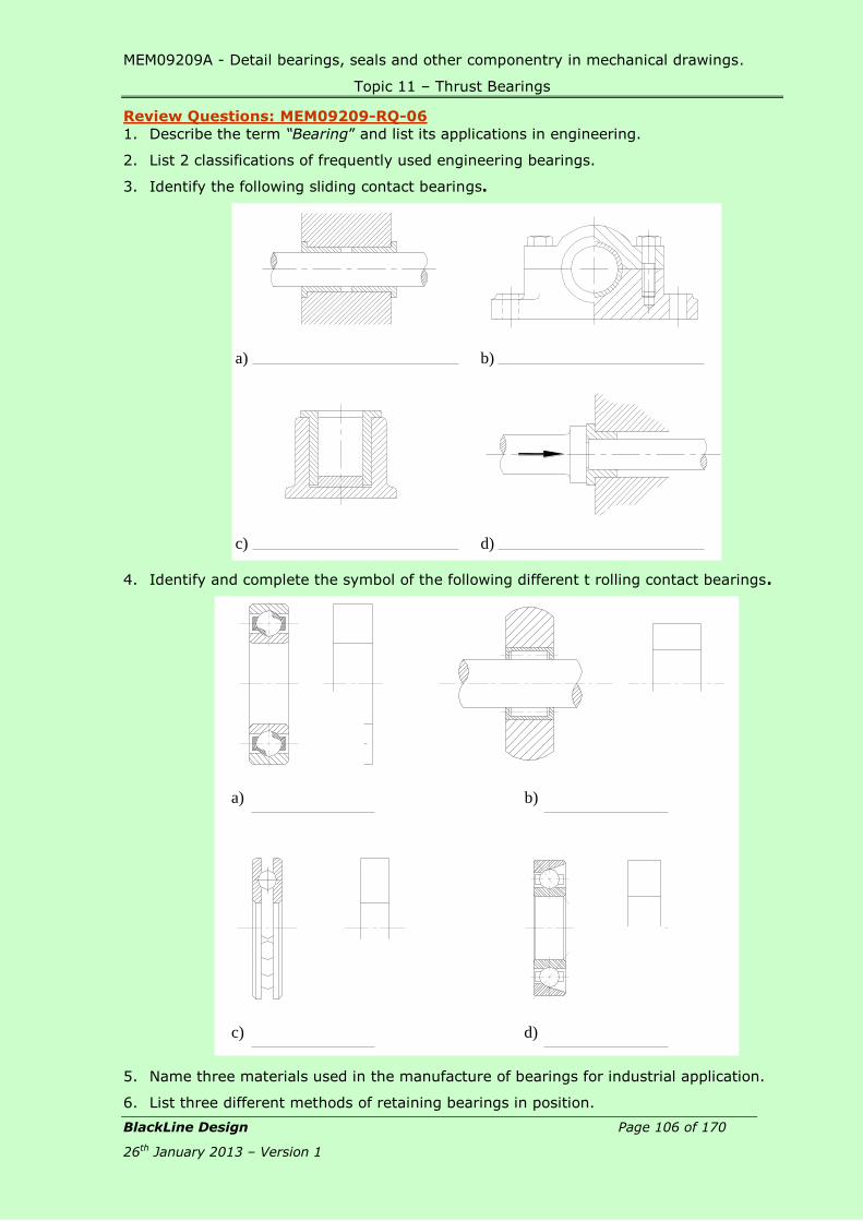
MEM09209A - Detail bearings, seals and other componentry in mechanical drawings.
Topic 11 – Thrust Bearings
BlackLine Design Page 106 of 170
26th January 2013 – Version 1
Review Questions: MEM09209-RQ-06
1. Describe the term “Bearing” and list its applications in engineering.
2. List 2 classifications of frequently used engineering bearings.
3. Identify the following sliding contact bearings.
4. Identify and complete the symbol of the following different t rolling contact bearings.
5. Name three materials used in the manufacture of bearings for industrial application.
6. List three different methods of retaining bearings in position.
b)a)
c) d)
a)
c)
b)
d)

MEM09209A - Detail bearings, seals and other componentry in mechanical drawings.
Topic 11 – Thrust Bearings
BlackLine Design Page 107 of 170
26th January 2013 – Version 1
Skill Practice Exercises:
Skill Practice Exercise: MEM09209-SP-1101
1. Create a new drawing using the template called MF Overhung Oil Handling Pump
located on the network drive and complete the assembly by adding the bearings,
keyseats and hatching where required. Provide a Bearing Retaining Cap to suit the
Shaft, Bearing and Shaft Housing.
2. Produce an assembly drawing of the MF Overhung Oil Handling Pump including a
Parts List and cross-referencing.
3. Produce detail drawings of the Shaft Housing, Bearing Retaining Cap and Shaft
assigning the appropriate toleranced dimensions to take the bearings with the
following fit classifications:
S7-h6 fit between the Bearing and Shaft Housing,
C11-h11 fit between the Shaft and the Bearings,
H7-h6 fit between the Bearing Retaining Cap and the Shaft Housing,
H7-g6 fit between the Bearing Housing and the Main Pump Body.
4. All mating surfaces are to be machined to a surface finish of 0.2. Circular surfaces
are to be concentric to the datum centreline to 0.05 with a roundness of 0.1 while
all flat surfaces are to be perpendicular to 0.05 and flatness to 0.02.
5. Provide an appropriate keyseats in the shaft.
6. Insert an A3 sheet on all drawings and save the drawing in your work area as
MEM09209-SP-1101.
Material: Impeller Housing – Cast Iron; Shaft Housing – Cast Iron; Shaft – Mild Steel;
Bearing Retaining Cap – Mild Steel; Bearings & Fasteners – Commercial.

MEM09209A - Detail bearings, seals and other componentry in mechanical drawings.
Topic 11 – Thrust Bearings
BlackLine Design Page 108 of 170
26th January 2013 – Version 1
Skill Practice Exercise: MEM09209-SP-1102
1. Create a new drawing using the template called Cylinder Head Rotor located on
the network drive and complete the assembly by adding the bearings where
shown and modifying the Rotor Housing and Bearing Retaining Cap as required.
2. Produce an assembly drawing of the Cylinder Head Rotor including a Parts List
and cross-referencing.
3. Produce drawings of the Rotor Housing and Bearing Retaining Cap assigning the
appropriate toleranced dimensions to take the bearings assuming a D10-h9 fit for
Bearing 51204 and a H7-h6 fit for Bearing NU306. The Rotor Housing is circular
in shape.
4. All cylindrical surfaces for the bearings are to be reamed to a finish of 0.2, be
concentric to the datum centreline to 0.025 and roundness to 0.05. All straight
mating surfaces are to be milled to 0.4 and perpendicular to the centreline to 0.1.
5. Provide an appropriate keyseat in the shaft.
6. Insert an A3 sheet on both drawings and save the drawing in your work area as
MEM09209-SP-1102
The assembly is circular in shape. All toleranced dimensions are to be placed on the
drawing as Limit of Size.
Material: Rotor Housing – Cast Iron; Bearing Retaining Cap – Mild Steel; Shaft & Gear –
Mild Steel; Bearings & Fasteners – Commercial.

MEM09209A - Detail bearings, seals and other componentry in mechanical drawings.
Topic 12 – Bearing Materials
BlackLine Design Page 109 of 170
26th January 2013 – Version 1
Topic 12 – Bearing Materials:
Required Skills:
Select suitable bearing materials to an application.
Required Knowledge:
Materials used in the manufacture of metal bearings.
Materials used in the manufacture of non-metal bearings
Plain Bearing Materials Metallic surfaces sliding together under load have a tendency to adhere causing tearing
or scoring of surfaces, heat generation results and finally seizure. This factor is of
primary importance in all bearing design. To counter this problem the designer’s aim is
to use materials with suitable lubricants to minimise this effect. A bearing material
should, if possible provide the following characteristics:
Have a good resistance to wear, fatigue and corrosion
Have sufficient strength to support the load
Have a fairly high melting point- to reduce the tendency for creep in use
Have suitable thermal properties to enable heat to be conducted away
As metal to metal contact will be unavoidable in service the material should be
selected to minimise seizure, fretting, scoring and welding
The bearing should be tolerant to dirt and foreign matter- e.g. soft surface
Should be tolerant to misalignment
Should be compatible to lubricant used- e.g. should not corrode if water is
used
Metal Bearings Porous bearings of sintered metals, usually plain or leaded bronze or iron are moulded to
shape under pressure and this process results in a sponge like structure with from 10-
35% of the metal volume as voids. This allows for impregnating with oil or graphite. In
operation the oil feeds through the interconnecting pores to the bearing surface. The
overall loss of oil is low although from time to time the bearing has to be re-impregnated.
Methods available for continuously fed oil to porous bearing use force feeding or very
simple wick feeds. Porous bearings are very useful in locations with limited access and
/or where regular lubrication or engineered lubrication systems are difficult to implement.
Porous bearings i.e. Oilite bearings, which are porous bronze or iron alloy impregnated
with an oil lubricant, are widely used throughout industry.
Aluminium bronze bearings
Bearings great strength can be produced using iron, silicon, and nickel as alloying
elements. The have excellent shock, wear and corrosion resistance. Their strength is
retained at elevated temperatures so they can be used in equipment operating above
260°C. This alloy however has poor compatibility, poor embedding properties and poor
conformability and so is best suited to heavy duty low speed applications with good
lubrication.
Aluminium Based materials
These materials were developed as an improvement on the white metal and copper
based alloys and to provide bearings that carry high loads. Special features are their
good resistance to corrosion, high thermal conductivity and high fatigue strength, high
thermal conductivity and high fatigue strength but they have the disadvantages of only
moderate embedding properties, poor compatibility and high coefficients of thermal
expansion. If used as solid unbacked bearings this type of alloy is usually too weak to

MEM09209A - Detail bearings, seals and other componentry in mechanical drawings.
Topic 12 – Bearing Materials
BlackLine Design Page 110 of 170
26th January 2013 – Version 1
maintain an interference fit and too hard to run satisfactorily against an unhardened
shaft. As a bearing material unalloyed aluminium has a tendency to seize to a steel
mating surface. It was found that a 20% of tin added to the aluminium improved
seizure resistance and that cold working and annealing helped to prevent
brittleness. The difference in coefficients between aluminium and steel necessitates
work hardening the bearing before use to prevent loosening in service.
Cadmium Alloys
These alloys have greater high temperature lives and a greater resistance to fatigue than
whitemetal bearings but are more subject to corrosion which can be overcome by plating
with indium. Cadmium has a low affinity for steel and so does not seize
easily. Cadmium materials are not widely used because of their high cost.
Cast Iron
Cast iron is an inexpensive bearing material for operation under relatively light loads.
Grey cast iron is widely used for machine tool beds due to its damping characteristics.
The presence of graphite in the iron improves running properties. The bearing surface is
often machined directly into the cast iron structure. Generous lubrication and large
clearances are necessary to avoid scoring. A speed of 0.8 m / s and a pressure of no
greater than 3.5 MPa are the maximum duty for cast iron bearings. Because of poor
conformability it is essential that the bearings have good alignment and freedom from
contamination.
Copper Based Alloys
Copper based alloys are considerably harder and strong, have better high temperature
characteristics, have greater resistance but poorer anti- scoring properties than the white
metals. There are four main classes of these alloys.
Copper Lead Alloys
Copper lead bearings contain 20% to 40% lead. Copper lead alloy bearings have less
resistance to seizure than the white metal but more than twice the fatigue resistance
even at high loads and temperatures. Hardened journals or lead-tin or lead indium
plating of the bearing surface can help to reduce the wear. Copper lead alloy bearings
are used in heavy duty bearings that carry moderate loads in high speed applications
Leaded Bronze Alloys
These combine good compatibility characteristics with excellent coating and easy
machining properties and have good structural properties and high load capacity. These
are inexpensive and are useful as a single material without the need for a separate
overlay or steel backing.
Silver
Silver bearings are highly resistant to fatigue but their anti-friction qualities are inferior
to the whitemetal bearings. A disadvantage is that they become readily welded to the
shaft even if the oil film breaks down for only and instant. They also do not possess the
embedding properties of other softer bearing metals. Silver bearings are often overlaid
with lead and indium or lead and tin, to provide better resistance to seizure. The
corrosion resistance, temperature strength ratio and thermal conductivity are all
good. Hard shafts are necessary with silver bearings and bearing loads of above 28.0
MPa may be carried at speed of 10 m/s.
Sintered Materials
Sintered metal bearings are made from powdered bronze plain, leaded bronze, iron or
stainless steel which, when subjected to high pressure and temperature, forms a porous
material. The finished bearings are self-lubricating as the material contains oil
impregnated in the pores. Sintered bearings are used where lubrication supply is
difficult, infrequent or inadequate.
Steel
As with cast iron, steel bearings required lots of lubrication and generous
clearances. Nickel steel bearings are best operated with intermittent loads rather than
continuously and using low journal speeds and temperatures less than 40°C.

MEM09209A - Detail bearings, seals and other componentry in mechanical drawings.
Topic 12 – Bearing Materials
BlackLine Design Page 111 of 170
26th January 2013 – Version 1
Tin bronze
These usually contain small percentages of tin and lead to aid machining and small
amounts of zinc and nickel are often added to improve strength. They are restricted to
low speed applications but will carry heavy loads.
Whitemetals or Babbit Metals
These are typically:
tin based (88% Sn-Tin, 4% Cu-Copper, 8% Sb-Antimony),
lead based (80% Pb-Lead, 14% Sb-Antimony, 6% Sn-Tin).
The materials have properties that include hardness combined with ductility, a structure
that holds lubricant, little tendency to cause wear to journals, they embed dirt easily and
are easily cast. The two types are generally interchangeable but the tin based ones are
usually more expensive , have better wear resistance, stand higher loads and are not as
brittle and are more corrosion resisting than the lead based bearings.
Non-metal Bearings
Carbon-Graphite
These materials are self-lubricating, stable at temperatures up to 400°C and resistant to
attack by chemicals and solvents. Bearings are moulded or machined from solid. The
material is used for applications where lubrication with grease of oil is not practical. In
some cases metal alloys may be added to the composition to carbon-graphite alloy to
improve the compressive strength. Graphite is too weak for use by itself therefore; tiny
graphite flakes are generally bonded with carbon or thermosetting resins.
Cermets
Certain hard carbides such as pressed and sintered titanium carbide or tungsten carbides
in a cobalt matrix can be used for high temperature applications for sliding components
in nuclear reactors and for other difficult duties. The cermet is very rigid, highly resistant
to corrosion and capable of taking a fine finish. Cermets have poor conformability, poor
impact resistance, are difficult to machine and are expensive. The outstanding property
of cermets is the resistance to wear.
Jewels
Jewel baring are usually made of sapphire or hard borosilicate glass and are used in low
torque instruments and control devices where low coefficient of friction, non-magnetic
properties and long life are required.
Plastics
The wide use of plastic bearings results from their freedom from corrosion, quiet
operation, availability in shapes and their good compatibility. Plastic bearings need little
lubrication and water can often be used for lubrication. Plastics are often resistant to
most chemicals including acids.
Phenolics or polyester resins reinforced with cotton fabric, asbestos, and glass
fibre are widely used and are very strong - up to 300Mpa in yield strength in
compression; they can be water lubricated and are useful where good
electrical insulation is needed. The thermal conductivity is low so the heat
generated by friction cannot easily be transmitted away through the
bearing. As a result heavier loaded bearings must have a feed of cooling or
lubricating fluid to remove the heat..
Nylon bearings are very satisfactory for light loads at high speeds. Nylon has
low friction characteristics and can be used with no lubrication. It is quiet in
operation, wears at a low rate when lubricated, is easily moulded and is
inexpensive..
PTFE has and exceptionally low coefficient of friction, is self-lubricating and is
resistant the most chemicals and operates at temperatures of up to 250
deg.C. However it has poor mechanical properties has low thermal
conductivity and has high coefficient of thermal expansion. In its pure form it
MEM09209A - Detail bearings, seals and other componentry in mechanical drawings.
Topic 12 – Bearing Materials
BlackLine Design Page 112 of 170
26th January 2013 – Version 1
is only useful at low speeds and loads. The mechanical properties of PTFE can
be improved by filling with glass fibre. PTFE is often made into a composite in
porous metals such as bronze or steel which results in a low friction material
with good mechanical properties. A widely used bearing design is based on
porous bronze filled with a PTFE/lead mixture supported by a steel backing
strip. PTFE filled with glass fibre and graphite or other inert materials are very
popular in mechanical and civil engineering.
Rubber
Natural rubber, and some synthetic types such as butatiene, acrynitrile, can be used as
bearings materials where resilience is needed with water as a lubricant. The bearings
usually consist of a fluted lining to a metal shell so that the shaft is carried on a series of
rubber strips running the length of the bearing. A flow of water is provided to cool the
bearing and to flush through any dirt collecting in the channels between the rubber
bearing strips; this type of bearing is used in marine applications and may be loaded up
to specific pressures of 0,4 Mpa.
Timber
Timber bearings can be manufactured from special hardwood (lignum vitae has an
inherent oiliness which makes it practically self-lubricating) have been used for large low
pressure, low speed bearings. The hardwoods absorb oil and grease and so little
attention is needed for maintenance; they do not score or seize their shaft but due to
uneven expansion and contraction large clearances are required. Timber is seldom used
in modern manufacture but would be used in historical renovations.
Teflon:
Teflon is part of the plastic family but has an exceptionally low coefficient of friction, high
resistance to chemicals, operates through a wide temperature range and is self-
lubricating.

MEM09209A - Detail bearings, seals and other componentry in mechanical drawings.
Topic 12 – Bearing Materials
BlackLine Design Page 113 of 170
26th January 2013 – Version 1
Skill Practice Exercises
Skill Practice Exercise: MEM09209-SP-1201
1. Create a new drawing using the template called Chopper Pump and complete the
assembly by adding the bearings, circlip, shaft keyway and hatching where
required.
2. Produce an assembly drawing of the Chopper Pump including a Parts List and
cross-referencing.
3. Produce detail drawings of the Pump Housing and Shaft assigning the appropriate
toleranced dimensions assuming a N7-h6 fit between the 6206 Bearing and
Bearing Housing and a F8-h7 fit between the 2-7206GG Bearing and the Bearing
Housing.
4. All flat mating surfaces are to be milled to a surface finish of 0.8 and circular
surfaces reamed or lathe machined to 0.2. Circular surfaces are to be concentric
to the datum centreline to 0.08 with a roundness of 0.2 while all flat surfaces are
to be perpendicular to 0.025 and flatness to 0.06.
5. Provide an appropriate keyseat in the shaft.
6. Insert an A3 sheet on the drawings and save the file in your work area as
MEM09209-SP-1201 prior to plotting.
The Pump Housing is circular in shape and fastened using 6 machine screws/bolts equally
spaced on the PCD. All toleranced dimensions are to be placed on the drawing as Limit
of Size.
Material: Impeller Housing – Aluminium Alloy; Impeller Adaptor Plate - Aluminium
Alloy; Pump Housing - Aluminium Alloy; Impeller – Nylon; Shaft – Stainless Steel;
Bearings, Fastenings & Seal – Commercial.
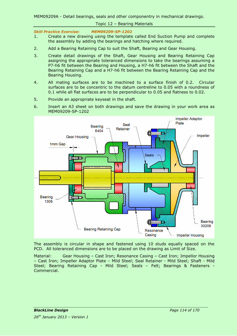
MEM09209A - Detail bearings, seals and other componentry in mechanical drawings.
Topic 12 – Bearing Materials
BlackLine Design Page 114 of 170
26th January 2013 – Version 1
Skill Practice Exercise: MEM09209-SP-1202
1. Create a new drawing using the template called End Suction Pump and complete
the assembly by adding the bearings and hatching where required.
2. Add a Bearing Retaining Cap to suit the Shaft, Bearing and Gear Housing.
3. Create detail drawings of the Shaft, Gear Housing and Bearing Retaining Cap
assigning the appropriate toleranced dimensions to take the bearings assuming a
P7-h6 fit between the Bearing and Housing, a H7-h6 fit between the Shaft and the
Bearing Retaining Cap and a H7-h6 fit between the Bearing Retaining Cap and the
Bearing Housing.
4. All mating surfaces are to be machined to a surface finish of 0.2. Circular
surfaces are to be concentric to the datum centreline to 0.05 with a roundness of
0.1 while all flat surfaces are to be perpendicular to 0.05 and flatness to 0.02.
5. Provide an appropriate keyseat in the shaft.
6. Insert an A3 sheet on both drawings and save the drawing in your work area as
MEM09209-SP-1202
The assembly is circular in shape and fastened using 10 studs equally spaced on the
PCD. All toleranced dimensions are to be placed on the drawing as Limit of Size.
Material: Gear Housing – Cast Iron; Resonance Casing – Cast Iron; Impellor Housing
– Cast Iron; Impeller Adaptor Plate – Mild Steel; Seal Retainer - Mild Steel; Shaft - Mild
Steel; Bearing Retaining Cap - Mild Steel; Seals – Felt; Bearings & Fasteners -
Commercial.

MEM09209A - Detail bearings, seals and other componentry in mechanical drawings.
Topic 13 - Lubrication
BlackLine Design Page 115 of 170
26th January 2013 – Version 1
Topic 13 – Lubrication:
Required Skills:
Required Knowledge:
Purposes for lubricating engineering components.
Methods of lubricating engineering components.
Lubrication materials.
Purpose for Lubricating Engineering Components: The purpose of bearing lubrication is to prevent direct metallic contact between the
various rolling and sliding elements. This is accomplished through the formation of a thin
oil (or grease) film on the contact surfaces. However, for rolling bearings, lubrication has
the following advantages:
Reduction of friction and wear
Dissipation of friction heat
Prolonged bearing life
Prevention of rust
Protection against harmful elements
In order to exhibit the effects, a lubrication method that matches service conditions must
be selected. In addition to the method to be used, a quality lubricant, the proper amount
of lubricant to be used, the bearing and seal must be designed to prevent foreign matter
from getting in or lubricant from leaking out.
Figure 13.1
Error! Reference source not found. shows the relationship between oil volume,
friction loss, and bearing temperature while Figure 13.2 details the characteristics of this
relationship.
MEM09209A - Detail bearings, seals and other componentry in mechanical drawings.
Topic 13 - Lubrication
BlackLine Design Page 116 of 170
26th January 2013 – Version 1
Range Characteristics Lubrication Method
A
When oil volume is extremely low, direct metallic contact occurs in places between the rolling elements and raceway surfaces. Bearing abrasion and seizing occur.
N.A.
B A thin oil film develops over all surfaces, friction is minimal and bearing temperature is low.
Grease lubrication, oil mist, air-oil lubrication
C As oil volume increases, heat build-up is balanced by cooling.
Circulating lubrication
D Regardless of oil volume, temperature increases at a fixed rate.
Circulating lubrication
E As oil volume increases, cooling predominates and bearing temperature decreases.
Forced circulation lubrication, Oil jet lubrication
Figure 13.2 - Oil Volume, Friction Loss, Bearing Temperature
As friction reduces, lubricants can be considered from two aspects. When a
hydrodynamic bearing is started, metal to metal contact occurs. Here, the actual
oiliness of the lubricant lowers the coefficient of friction between the two sliding surfaces.
In slider bearings operating on full fluid-film lubrication, the lubricant separates the two
sliding surfaces completely, and shearing of the lubricant is substituted for sliding
friction.
Any system of rolling elements, like ball bearings, should theoretically reduce friction
rapidly. If balls and rollers were perfectly smooth and inelastic, friction would be very
low. But materials deform and rolling elements slip under load; also, uncaged balls or
rollers tend to rub or slide against one another. When a separator or cage is present,
the rolling elements slide against it and the cage itself rubs against and gliding flange
surfaces. Because of this sliding, lubrication is needed to minimise wear and friction.
Methods of Lubrication: Lubrication methods, or lubrication technologies, are applied to convey lubricants in
certain time intervals and in agreed lubrication quantities in one or several lubrication
points. According to the lubrication methods, the lubricant is derived if necessary.
Lubrication methods find their application in the industrial lubrication, but also in many
other application fields. Thus lubrication methods have a basic necessity for all kinds of
vehicles, small machines, construction machines, agricultural machinery and also for
wind turbine technology.
In order to meet the ever growing demands of our highly engineered world, new
lubrication methods are constantly developed or the existing lubrication procedures are
further developed. Beside the different lubrication methods, play course the different
lubricants (lubrication media) a big role.
The constantly growing claims of industry are constantly researching innovative solutions
to different lubrication procedures and lubrication technologies.

MEM09209A - Detail bearings, seals and other componentry in mechanical drawings.
Topic 13 - Lubrication
BlackLine Design Page 117 of 170
26th January 2013 – Version 1
Jet:
Jet lubrication is often used for ultra-high-speed bearings such as
the bearings in jet engines. Lubricating oil is sprayed under
pressure from one or more nozzles directly into the bearing. The
figure shows an example of ordinary jet lubrication. The
lubricating oil is sprayed on the inner ring and cage guide face.
With high-speed operation, the air surrounding the bearing
rotates with it causing the oil to be deflected. The jetting speed of
the oil from the nozzle should be more than 20% of the
circumferential speed of the inner ring outer surface. More
uniform cooling and better temperature distribution are achieved
using more nozzles for a given amount of oil. It is desirable for
the oil to be forcibly discharged so the agitating resistance of the
lubricant can be reduced and the oil can effectively carry away
heat.
Mist:
Oil mist systems can also be referred to as “oil fog
lubrication” and are an effective system for lubricating
and cooling elements that require a limited quantity of
fluid in devices by generating a mist of oil that
separates the oil particles and distributes them through
the components. Due to the small amount of oil flow,
contamination in the vicinity of the bearing is low
because oil leakage is reduced. The systems are
supplied with reservoirs and used with either air
supplied from the work place or by self-contained air
compressors.
Splash:
Oil can be stored in a sump underneath moving
components; as the components start to rotate, they hit
the oil causing the oil to splash over all parts, both
stationary and moving, and provide lubrication. The
splash method has the advantage of the bearings not
being immersed in the oil.
Jet
Mist
Splash
Figure 13.3
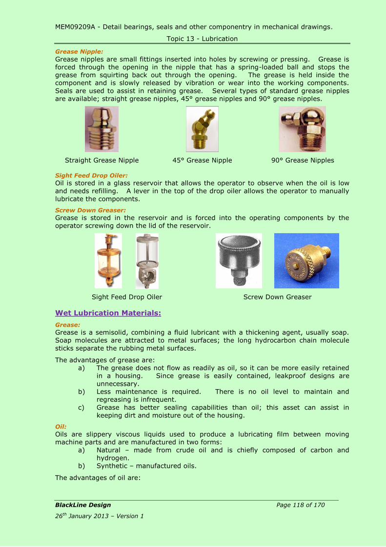
MEM09209A - Detail bearings, seals and other componentry in mechanical drawings.
Topic 13 - Lubrication
BlackLine Design Page 118 of 170
26th January 2013 – Version 1
Grease Nipple:
Grease nipples are small fittings inserted into holes by screwing or pressing. Grease is
forced through the opening in the nipple that has a spring-loaded ball and stops the
grease from squirting back out through the opening. The grease is held inside the
component and is slowly released by vibration or wear into the working components.
Seals are used to assist in retaining grease. Several types of standard grease nipples
are available; straight grease nipples, 45° grease nipples and 90° grease nipples.
Straight Grease Nipple 45° Grease Nipple 90° Grease Nipples
Sight Feed Drop Oiler:
Oil is stored in a glass reservoir that allows the operator to observe when the oil is low
and needs refilling. A lever in the top of the drop oiler allows the operator to manually
lubricate the components.
Screw Down Greaser:
Grease is stored in the reservoir and is forced into the operating components by the
operator screwing down the lid of the reservoir.
Sight Feed Drop Oiler
Screw Down Greaser
Wet Lubrication Materials:
Grease:
Grease is a semisolid, combining a fluid lubricant with a thickening agent, usually soap.
Soap molecules are attracted to metal surfaces; the long hydrocarbon chain molecule
sticks separate the rubbing metal surfaces.
The advantages of grease are:
a) The grease does not flow as readily as oil, so it can be more easily retained
in a housing. Since grease is easily contained, leakproof designs are
unnecessary.
b) Less maintenance is required. There is no oil level to maintain and
regreasing is infrequent.
c) Grease has better sealing capabilities than oil; this asset can assist in
keeping dirt and moisture out of the housing.
Oil:
Oils are slippery viscous liquids used to produce a lubricating film between moving
machine parts and are manufactured in two forms:
a) Natural – made from crude oil and is chiefly composed of carbon and
hydrogen.
b) Synthetic – manufactured oils.
The advantages of oil are:
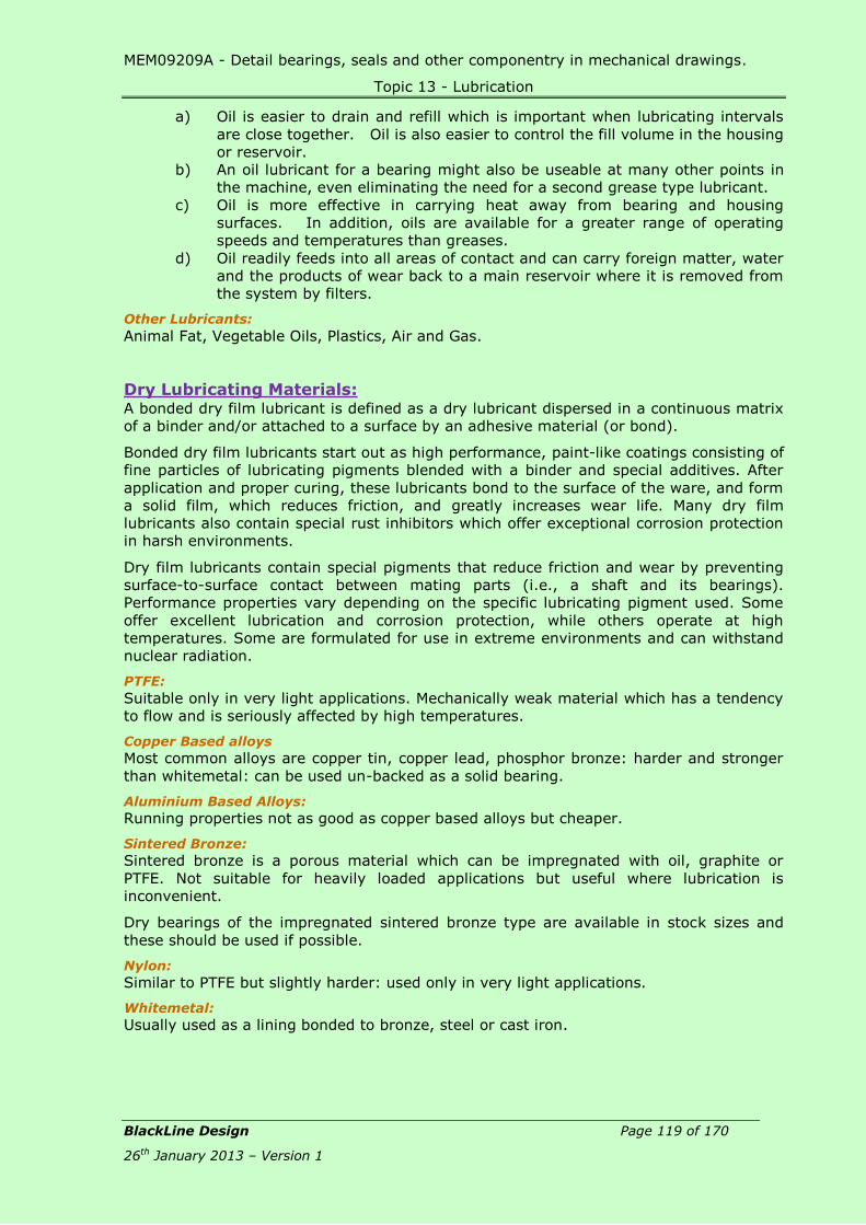
MEM09209A - Detail bearings, seals and other componentry in mechanical drawings.
Topic 13 - Lubrication
BlackLine Design Page 119 of 170
26th January 2013 – Version 1
a) Oil is easier to drain and refill which is important when lubricating intervals
are close together. Oil is also easier to control the fill volume in the housing
or reservoir.
b) An oil lubricant for a bearing might also be useable at many other points in
the machine, even eliminating the need for a second grease type lubricant.
c) Oil is more effective in carrying heat away from bearing and housing
surfaces. In addition, oils are available for a greater range of operating
speeds and temperatures than greases.
d) Oil readily feeds into all areas of contact and can carry foreign matter, water
and the products of wear back to a main reservoir where it is removed from
the system by filters.
Other Lubricants:
Animal Fat, Vegetable Oils, Plastics, Air and Gas.
Dry Lubricating Materials: A bonded dry film lubricant is defined as a dry lubricant dispersed in a continuous matrix
of a binder and/or attached to a surface by an adhesive material (or bond).
Bonded dry film lubricants start out as high performance, paint-like coatings consisting of
fine particles of lubricating pigments blended with a binder and special additives. After
application and proper curing, these lubricants bond to the surface of the ware, and form
a solid film, which reduces friction, and greatly increases wear life. Many dry film
lubricants also contain special rust inhibitors which offer exceptional corrosion protection
in harsh environments.
Dry film lubricants contain special pigments that reduce friction and wear by preventing
surface-to-surface contact between mating parts (i.e., a shaft and its bearings).
Performance properties vary depending on the specific lubricating pigment used. Some
offer excellent lubrication and corrosion protection, while others operate at high
temperatures. Some are formulated for use in extreme environments and can withstand
nuclear radiation.
PTFE:
Suitable only in very light applications. Mechanically weak material which has a tendency
to flow and is seriously affected by high temperatures.
Copper Based alloys
Most common alloys are copper tin, copper lead, phosphor bronze: harder and stronger
than whitemetal: can be used un-backed as a solid bearing.
Aluminium Based Alloys:
Running properties not as good as copper based alloys but cheaper.
Sintered Bronze:
Sintered bronze is a porous material which can be impregnated with oil, graphite or
PTFE. Not suitable for heavily loaded applications but useful where lubrication is
inconvenient.
Dry bearings of the impregnated sintered bronze type are available in stock sizes and
these should be used if possible.
Nylon:
Similar to PTFE but slightly harder: used only in very light applications.
Whitemetal:
Usually used as a lining bonded to bronze, steel or cast iron.
MEM09209A - Detail bearings, seals and other componentry in mechanical drawings.
Topic 13 - Lubrication
BlackLine Design Page 120 of 170
26th January 2013 – Version 1
Review Questions MEM09209-RQ-07:
1. List two purposes for lubricating engineering components.
2. List four methods of lubricating engineering components.
3. List four lubrication materials.
4. Provide two advantages of using grease as a lubricant.
5. Provide 2 advantages of using oil as a lubricant.
MEM09209A - Detail bearings, seals and other componentry in mechanical drawings.
Topic 13 - Lubrication
BlackLine Design Page 121 of 170
26th January 2013 – Version 1
Skill Practice Exercises
Skill Practice Exercise: MEM09209-SP-1301
Create a new drawing using the template called Solids Handling Pump and
complete the assembly by adding bearings, seal, normal fitting keys and hatching
where required.
Add a Bearing Retaining Cap to suit the Shaft, Bearing and Upper Housing.
Produce detail drawings of the Upper Housing, Shaft and Bearing Retaining Cap
assigning the appropriate toleranced dimensions to take the bearings assuming a
S7-h6 fit between the Bearing and Upper Housing, and a C11-h11 fit between the
Shaft and the Bearing Retaining Cap.
All flat surfaces are to be machined to a surface finish of 0.8, holes reamed to 0.4
and circular surfaces ground to 0.2.
Circular surfaces are to be concentric to the datum centreline to 0.05 with a
roundness of 0.1 while all flat surfaces are to be perpendicular to 0.05 and
flatness to 0.02.
Provide an appropriate keyseat in the shaft.
Insert an A3 sheet on both drawings and save the drawing in your work area as
MEM09209-SP-1301 before plotting.
The assembly is predominantly circular in shape with the components fastened
using 6 machine screws/bolts equally spaced on the PCD. All toleranced
dimensions are to be placed on the drawing as Limit of Size.
Materials: Upper Housing – Mild Steel; Bearing Casing - Mild Steel; Lower Housing -
Mild Steel; Outlet Pipe - Mild Steel; Bearing Retaining Cap - Mild Steel; O-Ring – Rubber;
Bearings and Fasteners – Commercial.

MEM09209A - Detail bearings, seals and other componentry in mechanical drawings.
Topic 13 - Lubrication
BlackLine Design Page 122 of 170
26th January 2013 – Version 1
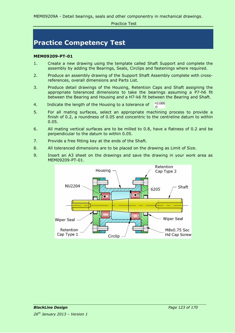
MEM09209A - Detail bearings, seals and other componentry in mechanical drawings.
Practice Test
BlackLine Design Page 123 of 170
26th January 2013 – Version 1
Practice Competency Test
MEM09209-PT-01
1. Create a new drawing using the template called Shaft Support and complete the
assembly by adding the Bearings, Seals, Circlips and fastenings where required.
2. Produce an assembly drawing of the Support Shaft Assembly complete with cross-
references, overall dimensions and Parts List.
3. Produce detail drawings of the Housing, Retention Caps and Shaft assigning the
appropriate toleranced dimensions to take the bearings assuming a P7-h6 fit
between the Bearing and Housing and a H7-k6 fit between the Bearing and Shaft.
4. Indicate the length of the Housing to a tolerance of
5. For all mating surfaces, select an appropriate machining process to provide a
finish of 0.2, a roundness of 0.05 and concentric to the centreline datum to within
0.05.
6. All mating vertical surfaces are to be milled to 0.8, have a flatness of 0.2 and be
perpendicular to the datum to within 0.05.
7. Provide a free fitting key at the ends of the Shaft.
8. All toleranced dimensions are to be placed on the drawing as Limit of Size.
9. Insert an A3 sheet on the drawings and save the drawing in your work area as
MEM09209-PT-01.

MEM09209A - Detail bearings, seals and other componentry in mechanical drawings.
Tables
BlackLine Design Page 124 of 170
26th January 2013 – Version 1
Tables
Table 1 – Internal Circlips
Most sizes over 170mm are without lugs Measurements are in mm Code
No. Bore
B
Circlip Dimensions Groove Dimensions
t Tol d Tol Cb b L h G Tol W n
8 0.80 +0.00
-0.05
8.7
+0.36
-0.10
3.0 1.1 2.4 1.0 8.4 +0.90
-0.00
0.9 0.6 INT0080
9 0.80 9.8 3.7 1.3 2.5 1.0 9.4 0.9 0.6 INT0090
10 1.00
+0.00
-0.06
10.8 3.3 1.4 3.2 1.2 10.4
+0.11
-0.00
1.0 0.6 INT0100
11 1.00 11.8 4.1 1.5 3.3 1.2 11.4 1.1 0.6 INT0110
12 1.00 13.0 4.9 1.7 3.4 1.5 12.5 1.1 0.8 INT0120
13 1.00 14.1 5.4 1.8 3.6 1.5 13.6 1.1 0.9 INT0130
14 1.00 15.1 6.2 1.9 3.7 1.7 14.6 1.1 0.9 INT0140
15 1.00 16.2 7.2 2.0 3.7 1.7 15.7 1.1 1.2 INT0150
16 1.00 17.3 8.0 2.0 3.8 1.7 16.8 1.1 1.2 INT0160
17 1.00 18.3
+0.42
-0.13
8.8 2.1 3.9 1.7 17.8 1.1 1.5 INT0170
18 1.00 19.5 9.4 2.2 4.1 2.0 19.0
+0.13
-0.00
1.1 1.5 INT0180
19 1.00 20.5 10.4 2.3 4.1 2.0 20.0 1.1 1.5 INT0190
20 1.00 21.5 11.2 2.4 4.2 2.0 21.0 1.1 1.5 INT0200
21 1.00 22.5 12.2 2.5 4.2 2.0 22.0 1.1 1.5 INT0210
22 1.00 26.5 13.2 2.6 4.2 2.0 23.0 1.3 1.5 INT0220
23 1.20 24.6
+0.42
-0.21
14.2 2.5 4.2 2.0 24.1 1.3 1.5 INT0230
24 1.20 25.9 14.8 2.6 4.4 2.0 25.2
-0.21
-0.00
1.3 1.8 INT0240
25 1.20 26.9 15.5 2.7 4.5 2.0 26.2 1.3 1.8 INT0250
26 1.20 27.9 16.1 2.8 4.7 2.0 27.2 1.3 1.8 INT0260
27 1.20 29.1 17.1 2.9 4.7 2.0 28.4 1.3 2.1 INT0270
28 1.20 30.1
+0.50
-0.25
17.9 2.9 4.8 2.0 29.4 1.3 2.1 INT0280
29 1.20 31.1 18.4 3.0 4.8 2.0 30.4
+0.25
-0.00
1.3 2.1 INT0290
30 1.20 32.1 19.9 3.0 4.8 2.0 31.4 1.3 2.1 INT0300
31 1.20 33.4 20.0 3.2 5.2 2.5 32.7 1.3 2.6 INT0310
32 1.20 33.4 20.6 3.2 5.4 2.5 33.7 1.3 2.6 INT0320
33 1.20 35.5 21.6 3.3 5.4 2.5 34.7 1.3 2.6 INT0330
34 1.50 36.5 22.6 3.3 5.4 2.5 35.7 1.6 2.6 INT0340
35 1.50 37.8 23.6 3.4 5.4 2.5 37.0 1.6 3.0 INT0350
36 1.50 38.8 24.6 3.5 5.4 2.5 38.0 1.6 3.0 INT0360

MEM09209A - Detail bearings, seals and other componentry in mechanical drawings.
Tables
BlackLine Design Page 125 of 170
26th January 2013 – Version 1
Most sizes over 170mm are without lugs Measurements are in mm Code
No. Bore
B
Circlip Dimensions Groove Dimensions
t Tol d Tol Cb b L h G Tol W n
37 1.50
+0.00
-0.06
39.8 +0.50
-0.25
25.4 3.6 5.5 2.5 39.0
+0.25
-0.00
1.6 3.0 INT0370
38 1.50 40.8 26.4 3.7 5.5 2.5 40.0 1.6 3.0 INT0380
39 1.50 42.0
+0.90
-0.39
27.2 3.8 5.6 2.5 41.0 1.6 3.0 INT0390
40 1.75 43.5 27.8 3.9 5.8 2.5 42.5 1.8 3.0 INT0400
41 1.75 44.5 28.6 4.0 5.9 2.5 43.5 1.8 3.8 INT0410
42 1.75 45.5 29.6 4.1 5.9 2.5 44.5 1.8 3.8 INT0420
43 1.75 46.5 30.6 4.2 5.9 2.5 45.5 1.8 3.8 INT0430
44 1.75 47.5 31.4 4.2 6.0 2.5 46.5 1.8 3.8 INT0440
45 1.75 48.5 32.0 4.3 6.2 2.5 47.5 1.8 3.8 INT0450
46 1.75 49.5 32.7 4.4 6.3 2.5 48.5 1.8 3.8 INT0460
47 1.75 50.5
+1.10
-0.46
33.5 4.4 6.4 2.5 49.5 1.8 3.8 INT0470
48 1.75 51.5 34.5 4.5 6.4 2.5 50.5
+0.30
-0.00
1.8 3.8 INT0480
50 2.00
+0.00
-0.07
54.2 36.3 4.6 6.5 2.5 53.0 2.15 4.5 INT0500
51 2.00 55.2 37.3 4.7 6.5 2.5 54.0 2.15 4.5 INT0510
52 2.00 56.2 37.9 4.7 6.7 2.5 55.0 2.15 4.5 INT0520
53 2.00 57.2 38.9 4.9 6.7 2.5 56.0 2.15 4.5 INT0530
54 2.00 58.2 39.9 5.0 6.7 2.5 57.0 2.15 4.5 INT0540
55 2.00
+0.00
-0.07
59.2
+1.10
-0.46
40.7 5.0 6.8 2.5 58.0 2.15 4.5 INT0550
56 2.00 60.2 41.7 5.1 6.8 2.5 59.0 2.15 4.5 INT0560
57 2.00 61.2 42.7 5.1 6.8 2.5 60.0 2.15 4.5 INT0570
58 2.00 62.2 43.5 5.2 6.9 2.5 61.0 2.15 4.5 INT0580
60 2.00 64.2 44.7 5.4 7.3 2.5 63.0 2.15 4.5 INT0600
62 2.00 66.2 46.7 5.5 7.3 2.5 65.0 2.15 4.5 INT0620
63 2.00 67.2 47.7 5.6 7.3 2.5 66.0 2.15 4.5 INT0630
64 2.00 68.2 48.2 5.7 7.5 2.5 67.0 2.15 4.5 INT0640
65 2.50 69.2 49.0 5.8 7.6 3.0 68.0 2.65 4.5 INT0650
67 2.50 71.5 50.8 6.0 7.7 3.0 70.0 2.65 4.5 INT0670
68 2.50 72.5 51.6 6.1 7.8 3.0 71.0 2.65 4.5 INT0680
70 2.50 74.5 53.6 6.2 7.8 3.0 73.0 2.65 4.5 INT0700
72 2.50 76.5 55.6 6.4 7.8 3.0 75.0 2.65 4.5 INT0720
75 2.50 79.5 58.6 6.6 7.8 3.0 78.0 2.65 4.5 INT0750
77 2.50 81.5 60.4 6.7 7.9 3.0 80.0 2.65 4.5 INT0770
78 2.50 82.5
+1.30
-0.54
60.1 6.8 8.5 3.0 81.0
+0.35
-0.00
2.65 5.3 INT0780
80 2.50 85.5 62.1 7.0 8.5 3.0 83.5 2.65 5.3 INT0800
82 2.50 87.5 64.1 7.0 8.5 3.0 85.5 2.65 5.3 INT0820
85 3.00
+0.00
-0.08
90.5 66.9 7.2 8.6 3.5 88.5 2.65 5.3 INT0850
87 3.00 92.5 68.9 7.3 8.6 3.5 90.5 3.15 5.3 INT0870
88 3.00 93.5 69.9 7.4 8.6 3.5 91.5 3.15 5.3 INT0880
90 3.00 95.5 71.9 7.6 8.6 3.5 93.5 3.15 5.3 INT0900
92 3.00 97.5 73.7 7.8 8.7 3.5 95.5 3.15 5.3 INT0920

MEM09209A - Detail bearings, seals and other componentry in mechanical drawings.
Tables
BlackLine Design Page 126 of 170
26th January 2013 – Version 1
Most sizes over 170mm are without lugs Measurements are in mm Code
No. Bore
B
Circlip Dimensions Groove Dimensions
t Tol d Tol Cb b L h G Tol W n
95 3.00 +0.00
-0.08
100.5
+1.30
-0.54
76.5 8.1 8.8 3.5 98.5
+0.35
-0.00
3.15 5.3 INT0950
97 3.00 102.5 78.5 8.2 8.8 3.5 100.5 3.15 5.3 INT0970
98 3.00 103.5 79.0 8.3 9.0 3.5 101.5 3.15 5.3 INT0980
100 3.00 105.5 80.6 8.4 9.2 3.5 103.5 3.15 5.3 INT1000
102 4.00
+0.00
-0.10
108.0 82.0 8.5 9.5 3.5 106.0
+0.54
-0.00
4.15 6.0 INT1020
105 4.00 112.0 85.0 8.7 9.5 3.5 109.0 4.15 6.0 INT1050
108 4.00 115.0 88.0 8.9 9.5 3.5 112.0 4.15 6.0 INT1080
110 4.00 117.0 88.2 9.0 10.4 3.5 114.0 4.15 6.0 INT1100
112 4.00 119.0 90.0 9.1 10.5 3.5 116.0 4.15 6.0 INT1120
115 4.00 122.0
+1.50
-0.63
93.0 9.3 10.5 3.5 119.0 4.15 6.0 INT1150
120 4.00 127.0 96.9 9.7 11.0 3.5 124.0
+0.63
-0.00
4.15 6.0 INT1200
125 4.00 132.0 101.9 10.0 11.0 4.00 129.0 4.15 6.0 INT1250
130 4.00 137.0 106.9 10.2 11.0 4.00 134.0 4.15 6.0 INT1300
135 4.00 142.0 111.5 10.5 11.2 4.00 139.0 4.15 6.0 INT1350
140 4.00 147.0 116.5 10.7 11.2 4.00 144.0 4.15 6.0 INT1400
145 4.00 152.0 121.0 10.9 11.4 4.00 149.0 4.15 6.0 INT1450
150 4.00 158.0 124.8 11.2 12.0 4.00 155.0 4.15 7.5 INT1500
155 4.00 164.0 129.8 11.4 12.0 4.00 160.0 4.15 7.5 INT1550
160 4.00 169.0 132.7 11.6 13.0 4.00 165.0 4.15 7.5 INT1600
165 4.00 174.5 137.7 11.8 13.0 4.00 170.0 4.15 7.5 INT1650
170 4.00 179.5 141.6 12.2 13.5 4.00 175.0 4.15 7.5 INT1700
175 4.00 184.5
+1.70
-0.72
146.6 12.7 13.5 4.00 180.0 4.15 7.5 INT1750
180 4.00 189.5 150.2 13.2 14.2 4.00 185.0
+0.72
-0.00
4.15 7.5 INT1800
185 4.00 194.5 155.2 13.7 14.2 4.00 190.5 4.15 7.5 INT1850
190 4.00 199.5 160.2 13.8 14.2 4.00 195.0 4.15 7.5 INT1900
195 4.00 204.5 165.2 13.8 14.2 4.00 200.0 4.15 7.5 INT1950
200 4.00 209.5 170.2 14.0 14.2 4.00 205.0 4.15 7.5 INT2000

MEM09209A - Detail bearings, seals and other componentry in mechanical drawings.
Tables
BlackLine Design Page 127 of 170
26th January 2013 – Version 1
Table 2 – External Circlips
Most sizes over 170mm are without lugs Measurements are in mm Code
No. Shaft Circlip Dimensions Groove Dimensions
t Tol d Tol Cs b L h G Tol W n
3 0.40
+0.00
-0.05
2.7
+0.04
-0.15
7.0 0.8 1.9 1.0 2.8 +0.00
-0.04 0.5 0.3 EXT0030
4 0.40 3.7 8.6 0.9 2.2 1.0 3.8 +0.00
-
0.048
0.5 0.3 EXT0040
5 0.60 4.7 10.3 1.1 2.5 1.0 4.8 0.7 0.3 EXT0050
6 0.70 5.6 11.7 1.3 2.7 1.2 5.7 0.8 0.5 EXT0060
7 0.80 6.5 +0.06
-0.18
13.5 1.4 3.1 1.2 6.7
+0.00
-0.06
0.9 0.5 EXT0070
8 0.80 7.4 14.7 1.5 3.2 1.2 7.6 1.1 0.6 EXT0080
9 0.80
+0.00
-0.06
8.4 16.0 1.7 3.3 1.2 8.6 1.1 0.6 EXT0090
10 1.00 9.3
+0.10
-0.36
17.0 1.8 3.3 1.5 9.6 1.1 0.6 EXT0100
11 1.00 10.2 18.0 1.8 3.3 1.5 10.5
+0.00
-0.11
1.1 0.8 EXT0110
12 1.00 11.0 19.0 1.8 3.3 1.7 11.5 1.1 0.8 EXT0120
13 1.00 11.9 20.2 2.0 3.4 1.7 12.4 1.1 0.9 EXT0130
14 1.00 12.9 21.4 2.1 3.5 1.7 13.4 1.1 0.9 EXT0140
15 1.00 13.8 22.6 2.2 3.6 1.7 14.3 1.1 1.1 EXT0150
16 1.00 14.7 23.8 2.2 3.7 1.7 15.2 1.1 1.2 EXT0160
17 1.00 15.7 25.0 2.3 3.8 1.7 16.2 1.1 1.2 EXT0170
18 1.00 16.5 26.2 2.4 3.9 2.0 17.0 1.3 1.5 EXT0180
19 1.00 17.5 27.2 2.5 3.9 2.0 18.0 1.3 1.5 EXT0190
20 1.00 18.5
+0.13
-0.42
28.4 2.6 4.0 2.0 19.0
+0.00
-0.21
1.3 1.5 EXT0200
21 1.00 19.5 29.6 2.7 4.0 2.0 20.0 1.3 1.5 EXT0210
22 1.00 20.5 30.8 2.8 4.2 2.0 21.0 1.3 1.5 EXT0220
23 1.20 21.5 32.0 2.9 4.3 2.0 22.0 1.3 1.5 EXT0230
24 1.20 22.2
+0.21
-0.42
33.2 3.0 4.4 2.0 22.9 1.3 1.7 EXT0240
25 1.20 23.2 34.2 3.0 4.4 2.0 23.9 1.3 1.7 EXT0250
26 1.20 24.2 35.5 3.1 4.5 2.0 24.9 1.3 1.7 EXT0260
27 1.20 24.9 36.7 3.1 4.6 2.0 25.6 1.3 2.1 EXT0270
28 1.20 25.9 37.9 3.2 4.7 2.0 26.6 1.6 2.1 EXT0280

MEM09209A - Detail bearings, seals and other componentry in mechanical drawings.
Tables
BlackLine Design Page 128 of 170
26th January 2013 – Version 1
Most sizes over 170mm are without lugs Measurements are in mm Code
No. Shaft Circlip Dimensions Groove Dimensions
t Tol d Tol Cs b L h G Tol W n
29 1.20
+0.00
-0.06
26.9 +0.21
-0.42
39.1 3.4 4.8 2.0 27.6 +0.00
-0.21
1.6 2.1 EXT0290
30 1.20 27.9 40.5 3.5 5.0 2.0 28.6 1.6 2.1 EXT0300
31 1.20 28.6 41.5 3.5 5.0 2.5 29.3 1.6 2.6 EXT0310
32 1.20 29.6
+0.25
-0.50
43.0 3.6 5.2 2.5 30.3
+0.00
-0.25
1.6 2.6 EXT0320
33 1.20 30.5 44.0 3.7 5.2 2.5 31.3 1.6 2.6 EXT0330
34 1.50 31.5 45.5 3.8 5.4 2.5 32.3 1.6 2.6 EXT0340
35 1.50 32.2 46.8 3.9 5.6 2.5 33.0 1.6 3.0 EXT0350
36 1.50 33.2 47.8 4.0 5.6 2.5 34.0 1.85 3.0 EXT0360
37 1.50 34.2 49.0 4.1 5.7 2.5 35.0 1.85 3.0 EX370T0
38 1.50 35.2 50.2 4.2 5.8 2.5 36.0 1.85 3.0 EXT0380
39 1.50 36.0 51.4 4.3 5.9 2.5 37.0 1.85 3.8 EXT0390
40 1.75 36.5 52.6 4.4 6.0 2.5 37.5 1.85 3.8 EXT0400
41 1.75 37.5 54.1 4.5 6.2 2.5 38.5 1.85 3.8 EXT0410
42 1.75 38.5
+0.39
-0.90
55.7 4.5 6.5 2.5 39.5 1.85 3.8 EXT0420
43 1.75 39.5 56.7 4.6 6.6 2.5 40.5 1.85 3.8 EXT0430
44 1.75 40.5 57.9 4.6 6.7 2.5 41.5 1.85 3.8 EXT0440
45 1.75 41.5 59.1 4.7 6.7 2.5 42.5 1.85 3.8 EXT0450
46 1.75 42.5 60.1 4.8 6.8 2.5 43.5 1.85 3.8 EXT0460
47 1.75 43.5 61.3 4.9 6.9 2.5 44.5 1.85 3.8 EXT0470
48 1.75 44.5 62.5 5.0 6.9 2.5 45.5 1.85 3.8 EXT0480
50 2.00
+0.00
-0.07
45.8 64.5 5.1 6.9 2.5 47.0 2.15 4.5 EXT0500
51 2.00 46.8 65.7 5.2 7.0 2.5 48.0 2.15 4.5 EXT0510
52 2.00 47.8 66.7 5.2 7.0 2.5 49.0 2.15 4.5 EXT0520
53 2.00 48.8 68.0 5.3 7.1 2.5 50.0 2.15 4.5 EXT0530
54 2.00 49.8
+0.46
-1.10
69.0 5.3 7.1 2.5 51.0
+0.00
-0.30
2.15 4.5 EXT0540
55 2.00 50.8 70.2 5.4 7.2 2.5 52.0 2.15 4.5 EXT0550
56 2.00 51.8 71.6 5.5 7.3 2.5 53.0 2.15 4.5 EXT0560
57 2.00 52.8 72.4 5.5 7.3 2.5 54.0 2.15 4.5 EXT0570
58 2.00 53.8 73.6 5.6 7.3 2.5 55.0 2.15 4.5 EXT0580
60 2.00
+0.00
-0.07
55.8
+0.46
-1.10
75.6 5.8 7.4 2.5 57.0
+0.00
-0.30
2.15 4.5 EXT0600
62 2.00 57.8 77.8 6.0 7.5 2.5 59.0 2.15 4.5 EXT0620
63 2.00 58.8 79.0 6.2 7.6 2.5 60.0 2.15 4.5 EXT0630
65 2.50 62.5 81.4 6.3 7.8 3.0 62.0 2.65 4.5 EXT0650
67 2.50 63.5 83.6 6.4 7.9 3.0 64.0 2.65 4.5 EXT0670
68 2.50 63.5 84.4 6.5 8.0 3.0 65.0 2.65 4.5 EXT0680
70 2.00 65.5 87.0 6.6 8.1 3.0 67.0 2.65 4.5 EXT0700
72 2.00 67.5 89.2 6.8 8.2 3.0 69.0 2.65 4.5 EXT0720
75 2.00 70.5 92.7 7.0 8.4 3.0 72.0 2.65 4.5 EXT0750
77 2.00 72.5 94.9 7.2 8.5 3.0 74.0 2.65 4.5 EXT0770
78 2.50 73.5 96.1 7.3 8.6 3.0 75.0 2.65 4.5 EXT0780

MEM09209A - Detail bearings, seals and other componentry in mechanical drawings.
Tables
BlackLine Design Page 129 of 170
26th January 2013 – Version 1
Most sizes over 170mm are without lugs Measurements are in mm Code
No. Shaft Circlip Dimensions Groove Dimensions
t Tol d Tol Cs b L h G Tol W n
80 2.50 +0.00
-0.07
74.5 +0.46
-1.10
98.1 7.4 8.6 3.0 76.5 +0.00
-0.30
2.65 5.3 EXT0800
82 3.00 76.5 100.3 7.6 8.7 3.0 78.5 2.65 5.3 EXT0820
85 3.00
+0.00
-0.08
79.5 100.3 7.8 8.7 3.5 81.5
+0.00
-0.35
3.15 5.3 EXT0850
87 3.00 81.5
+0.54
-1.30
105.5 7.9 8.8 3.5 83.5 3.15 5.3 EXT0870
88 3.00 82.5 106.5 8.0 8.8 3.5 84.5 3.15 5.3 EXT0880
90 3.00 84.5 108.5 8.2 8.8 3.5 86.5 3.15 5.3 EXT0900
92 3.00 86.5 111.0 8.4 9.0 3.5 88.5 3.15 5.3 EXT0920
95 3.00 89.5 114.8 8.6 9.4 3.5 91.5 3.15 5.3 EXT0950
97 3.00 91.5 116.8 8.8 9.4 3.5 93.5 3.15 5.3 EXT0970
98 3.00 92.5 118.0 9.0 9.5 3.5 94.5 3.15 5.3 EXT0980
100 3.00 94.5 120.2 9.0 9.6 3.5 96.5 3.15 5.3 EXT1000
102 4.00
+0.00
-0.10
95.0 122.4 9.2 9.7 3.5 98.0
+0.00
-0.54
4.15 6.0 EXT1020
105 4.00 98.0 125.8 9.3 9.9 3.5 101.0 4.15 6.0 EXT1050
108 4.00 101.0 129.0 9.5 10.0 3.5 104.0 4.15 6.0 EXT1080
110 4.00 103.0 131.2 9.6 10.1 3.5 106.0 4.15 6.0 EXT1100
112 4.00 105.0 133.7 9.7 10.3 3.5 108.0 4.15 6.0 EXT1120
115 4.00 108.0 133.7 9.8 10.6 3.5 111.0 4.15 6.0 EXT1150
120 4.00 113.0 143.1 10.2 11.0 3.5 116.0 4.15 6.0 EXT1200
125 4.00 118.0 149.0 10.4 11.4 4.0 121.0
+0.00
-0.63
4.15 6.0 EXT1250
130 4.00 123.0
+0.63
-1.50
154.4 10.7 11.6 4.0 126.0 4.15 6.0 EXT1300
135 4.00 128.0 159.8 11.0 11.8 4.0 131.0 4.15 6.0 EXT1350
140 4.00 133.0 165.2 11.2 12.0 4.0 136.0 4.15 6.0 EXT1400
145 4.00 138.0 170.6 11.5 12.2 4.0 141.0 4.15 6.0 EXT1450
150 4.00 142.0 177.3 11.8 13.0 4.0 145.0 4.15 6.0 EXT1500
155 4.00 146.0 182.3 12.0 13.0 4.0 150.0 4.15 7.5 EXT1550
160 4.00 151.0 188.0 12.2 13.3 4.0 155.0 4.15 7.5 EXT1600
165 4.00 155.5 193.4 12.5 13.5 4.0 160.0 4.15 7.5 EXT1650
170 4.00 160.5 198.4 12.9 13.5 4.0 165.0 4.15 7.5 EXT1700
175 4.00 165.5 203.4 12.9 13.5 4.0 170.0 4.15 7.5 EXT1750
180 4.00 170.5 210.0 14.0 14.2 4.0 175.0 4.15 7.5 EXT1800
185 4.00 175.5 215.0 14.0 14.2 4.0 180.0 4.15 7.5 EXT1850

MEM09209A - Detail bearings, seals and other componentry in mechanical drawings.
Tables
BlackLine Design Page 130 of 170
26th January 2013 – Version 1
Table 3 – Deep Groove Ball Bearings
Principal
Dimensions Mass Part No. Dimensions
Abutment & Fillet
Dimensions
mm kg mm mm
d D B d1 D1 r da Da max Ra Max
17 26 5 0.0082 61803 20.2 23.2 0.3 19 24 0.3
35 8 0.032 16003 22.8 29.5 0.3 19 33 0.3
35 10 0.039 6003 22.8 29.5 0.3 19 33 0.3
40 12 0.065 6203 2402 32.9 0.6 21 36 0.6
47 14 0.12 6303 26.5 37.6 1 22 42 1
62 17 0.27 6403 32.4 47.4 1.1 23.5 55.5 1
20 32 7 0.018 61804 24 28.3 0.3 22 30 0.3
42 8 0.050 16004 27.2 34.6 0.3 22 40 0.3
42 12 0.069 6004 27.2 35.1 0.6 24 38 0.6
47 14 0.11 6204 28.5 38.7 1 25 42 1
52 15 0.14 6304 30.3 42.1 1.1 26.5 45.5 1
72 19 0.40 6404 37.1 55.6 1.1 26.5 65.5 1
25 37 7 0.022 61805 29 33 0.3 27 35 0.3
47 8 0.060 16005 33.3 40.7 0.3 27 45 0.3
47 12 0.080 6005 32 40.3 0.6 29 43 0.6
52 15 0.13 6205 34 44.2 1 30 47 1
62 17 0.23 6305 36.6 50.9 1.1 31.5 55.5 1
80 21 0.53 6405 45.4 63.8 1.5 33 72 1.5
30 52 7 0.026 61806 33.8 38.2 0.3 32 40 0.3
55 9 0.085 16006 38 47.3 0.3 32 53 0.3
55 13 0.12 6006 38.2 47.1 1 35 50 1
62 16 0.20 6206 40.3 52.1 1 35 57 1
72 19 0.35 6306 44.6 59.9 1.1 36.5 65.5 1
90 23 0.74 6406 50.3 70.7 1.5 38 82 1.5

MEM09209A - Detail bearings, seals and other componentry in mechanical drawings.
Tables
BlackLine Design Page 131 of 170
26th January 2013 – Version 1
35 47 7 0.030 61807 38.8 43.2 0.3 37 45 0.3
62 9 0.11 16007 44 53.3 0.3 37 60 0.3
62 14 0.16 6007 43.7 53.6 1 40 57 1
72 17 0.29 6207 46.9 60.6 1.1 41.5 65.5 1
80 21 0.46 6307 49.5 66.1 1.5 43 72 1.5
100 25 0.95 6407 57.4 80.6 1.5 43 92 1.5
40 52 7 0.034 61808 43.8 48.2 0.3 42 50 0.3
68 9 0.13 16008 49.4 57 0.3 42 66 0.3
68 15 0.19 6008 49.2 59.1 1 45 63 1
80 18 0.37 6208 52.6 67.9 1.1 46.5 73.5 1
90 23 0.63 6308 56.1 74.7 1.5 48 82 1.5

MEM09209A - Detail bearings, seals and other componentry in mechanical drawings.
Tables
BlackLine Design Page 132 of 170
26th January 2013 – Version 1
Table 4 – Self Aligning Ball Bearings
Boundary Dimensions Mass Part Number Dimensions Abutment & Fillet
Dimensions
d D B Cyl.
Bore
Taper
Bore
d2 D1 R
Min
da
Min
Da
max
Ra
max
mm kg mm mm
17 40 12 0.16 1203 - 24.2 33.7 1 21 36 0.6
40 16 0.19 2203 - 23.5 34.3 1 21 36 0.6
47 14 0.29 1303 - 26.4 38.3 1.5 22 42 1
47 19 0.35 2303 - 25.8 39.4 1.5 22 42 1
20 47 14 0.26 1204 - 28.9 39.1 1.5 25 42 1
47 18 0.31 2204 - 28.0 40.4 1.5 25 42 1
52 15 0.35 1304 - 31.3 43.6 2 26.5 45.5 1
52 21 0.46 2304 - 28.8 43.7 2 26.5 45.5 1
25 52 15 0.31 1205 1205K 33.1 44.9 1.5 30 47 1
52 18 0.35 2205 2205K 33.0 44.7 1.5 30 47 1
62 17 0.57 1305 1305K 37.8 52.5 2 31.5 55.5 1
62 24 0.75 2305 2305K 35.2 52.5 2 31.5 55.5 1
30 62 16 0.48 1206 1206K 40.1 53.2 1.5 35 57 1
62 20 0.57 2206 2206K 40.0 53.0 1.5 35 57 1
72 19 0.86 1306 1306K 44.9 60.9 2 36.5 65.5 1
72 27 1.10 2306 2306K 41.7 60.9 2 36.5 65.5 1

MEM09209A - Detail bearings, seals and other componentry in mechanical drawings.
Tables
BlackLine Design Page 133 of 170
26th January 2013 – Version 1
Boundary Dimensions Mass Part Number Dimensions Abutment & Fillet
Dimensions
d D B Cyl.
Bore
Taper Bore
d2 D1 R
Min
da
Min
Da
max
Ra
max
mm kg mm mm
35 72 17 0.71 1207 1207K 47.5 60.7 2 41.5 65.5 1
72 23 0.88 2207 2207K 46.0 62.2 2 41.5 65.5 1
80 21 1.10 1307 1307K 51.5 69.5 2.5 43 72 1.5
80 31 1.50 2307 2307K 46.5 68.4 2.5 43 72 1.5
40 80 18 0.93 1208 1208K 53.6 68.8 2 46.5 73.5 1
80 23 1.10 2208 2208K 52.4 68.8 2 46.5 73.5 1
90 23 1.60 1308 1308K 57.5 76.8 2.5 48 82 1.5
90 33 2.05 2308 2308K 53.5 76.8 2.5 48 82 1.5

MEM09209A - Detail bearings, seals and other componentry in mechanical drawings.
Tables
BlackLine Design Page 134 of 170
26th January 2013 – Version 1
Table 5 - Angular Contact Ball Bearing
Principal Dimensions
Mass Part No. Dimensions Abutment & Fillet
Dimensions
D d B d1 D1 R a da Da
max
Ra
max
mm kg mm mm
20 42 12 0.33 7004 C 26.9 35.1 1 10 25 37 0.6
42 24 0.68 2 x 7004 CG 26.9 35.1 1 10 25 37 0.6
47 14 0.48 7204 C 29.1 38.7 1.5 12 26 41 1
47 14 0.58 7204 B 30.7 36.7 1.5 21 26 41 1
47 28 0.97 2 x 7204 CG 29.1 38.7 1.5 12 26 41 1
47 28 1.08 2 x 7024 BG 30.7 36.7 1.5 21 26 41 1
52 15 0.73 304 B 32.7 39.9 2 23 27 45 1
52 30 1.45 2 x 7304 BG 32.7 39.9 2 23 27 45 1
25 47 12 0.40 7005 C 31.9 40.1 1 11 30 42 0.6
47 24 0.77 2 x 7005 CG 31.9 40.1 1 11 30 42 0.6
52 15 0.57 7205 C 34.1 43.7 1.5 13 31 46 1
52 15 0.68 7205 B 36.3 42.3 1.5 24 31 46 1
52 30 1.17 2 x 7205 CG 34.1 43.7 1.5 13 31 46 1
52 30 1.36 2 x 7205 BG 36.3 42.3 1.5 24 31 46 1
62 17 1.17 7205 B 39.6 48 2 27 32 55 1
62 34 2.31 2 x 7305 BG 39.6 48 2 27 32 55 1
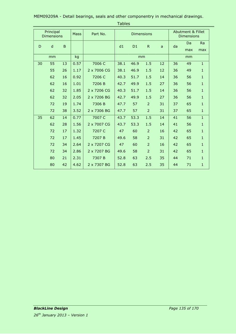
MEM09209A - Detail bearings, seals and other componentry in mechanical drawings.
Tables
BlackLine Design Page 135 of 170
26th January 2013 – Version 1
Principal
Dimensions Mass Part No. Dimensions
Abutment & Fillet
Dimensions
D d B d1 D1 R a da Da
max
Ra
max
mm kg mm mm
30 55 13 0.57 7006 C 38.1 46.9 1.5 12 36 49 1
55 26 1.17 2 x 7006 CG 38.1 46.9 1.5 12 36 49 1
62 16 0.92 7206 C 40.3 51.7 1.5 14 36 56 1
62 16 1.01 7206 B 42.7 49.9 1.5 27 36 56 1
62 32 1.85 2 x 7206 CG 40.3 51.7 1.5 14 36 56 1
62 32 2.05 2 x 7206 BG 42.7 49.9 1.5 27 36 56 1
72 19 1.74 7306 B 47.7 57 2 31 37 65 1
72 38 3.52 2 x 7306 BG 47.7 57 2 31 37 65 1
35 62 14 0.77 7007 C 43.7 53.3 1.5 14 41 56 1
62 28 1.56 2 x 7007 CG 43.7 53.3 1.5 14 41 56 1
72 17 1.32 7207 C 47 60 2 16 42 65 1
72 17 1.45 7207 B 49.6 58 2 31 42 65 1
72 34 2.64 2 x 7207 CG 47 60 2 16 42 65 1
72 34 2.86 2 x 7207 BG 49.6 58 2 31 42 65 1
80 21 2.31 7307 B 52.8 63 2.5 35 44 71 1
80 42 4.62 2 x 7307 BG 52.8 63 2.5 35 44 71 1
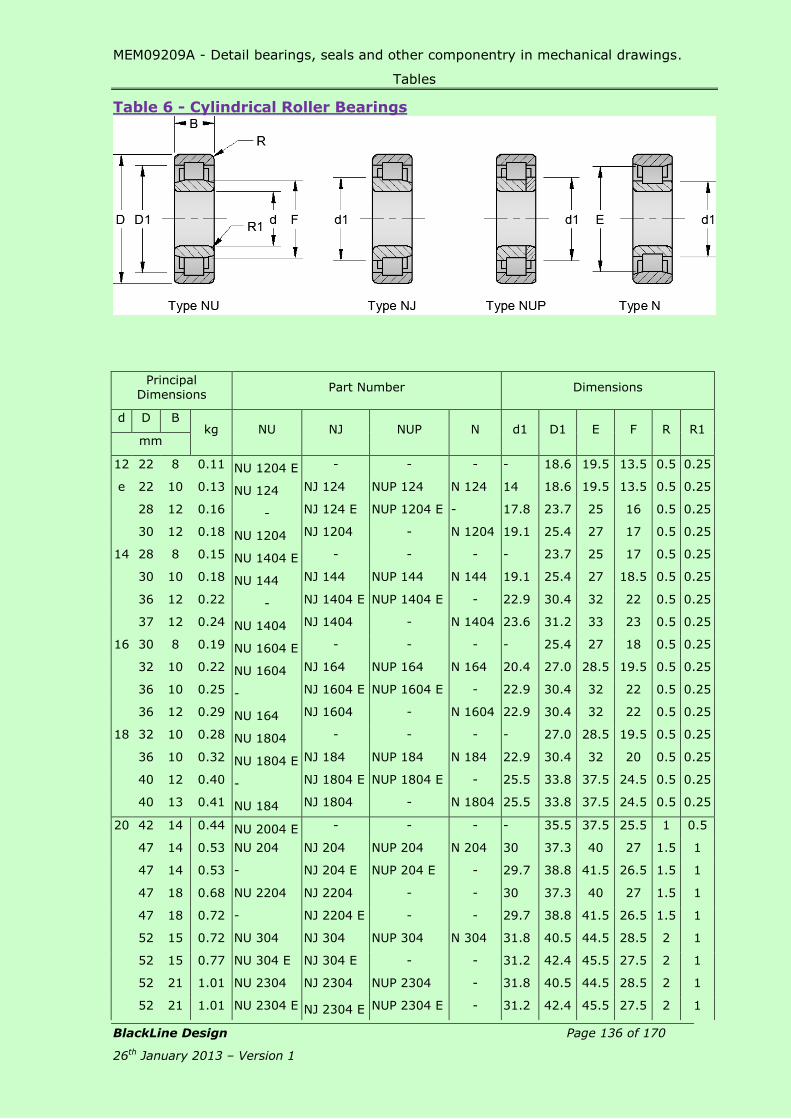
MEM09209A - Detail bearings, seals and other componentry in mechanical drawings.
Tables
BlackLine Design Page 136 of 170
26th January 2013 – Version 1
Table 6 - Cylindrical Roller Bearings
Principal Dimensions
Part Number Dimensions
d D B kg NU NJ NUP N d1 D1 E F R R1
mm
12 22 8 0.11 NU 1204 E - - - - 18.6 19.5 13.5 0.5 0.25
e 22 10 0.13 NU 124 NJ 124 NUP 124 N 124 14 18.6 19.5 13.5 0.5 0.25
28 12 0.16 - NJ 124 E NUP 1204 E - 17.8 23.7 25 16 0.5 0.25
30 12 0.18 NU 1204 NJ 1204 - N 1204 19.1 25.4 27 17 0.5 0.25
14 28 8 0.15 NU 1404 E - - - - 23.7 25 17 0.5 0.25
30 10 0.18 NU 144 NJ 144 NUP 144 N 144 19.1 25.4 27 18.5 0.5 0.25
36 12 0.22 - NJ 1404 E NUP 1404 E - 22.9 30.4 32 22 0.5 0.25
37 12 0.24 NU 1404 NJ 1404 - N 1404 23.6 31.2 33 23 0.5 0.25
16 30 8 0.19 NU 1604 E - - - - 25.4 27 18 0.5 0.25
32 10 0.22 NU 1604 NJ 164 NUP 164 N 164 20.4 27.0 28.5 19.5 0.5 0.25
36 10 0.25 - NJ 1604 E NUP 1604 E - 22.9 30.4 32 22 0.5 0.25
36 12 0.29 NU 164 NJ 1604 - N 1604 22.9 30.4 32 22 0.5 0.25
18 32 10 0.28 NU 1804 - - - - 27.0 28.5 19.5 0.5 0.25
36 10 0.32 NU 1804 E NJ 184 NUP 184 N 184 22.9 30.4 32 20 0.5 0.25
40 12 0.40 - NJ 1804 E NUP 1804 E - 25.5 33.8 37.5 24.5 0.5 0.25
40 13 0.41 NU 184 NJ 1804 - N 1804 25.5 33.8 37.5 24.5 0.5 0.25
20 42 14 0.44 NU 2004 E - - - - 35.5 37.5 25.5 1 0.5
47 14 0.53 NU 204 NJ 204 NUP 204 N 204 30 37.3 40 27 1.5 1
47 14 0.53 - NJ 204 E NUP 204 E - 29.7 38.8 41.5 26.5 1.5 1
47 18 0.68 NU 2204 NJ 2204 - - 30 37.3 40 27 1.5 1
47 18 0.72 - NJ 2204 E - - 29.7 38.8 41.5 26.5 1.5 1
52 15 0.72 NU 304 NJ 304 NUP 304 N 304 31.8 40.5 44.5 28.5 2 1
52 15 0.77 NU 304 E NJ 304 E - - 31.2 42.4 45.5 27.5 2 1
52 21 1.01 NU 2304 NJ 2304 NUP 2304 - 31.8 40.5 44.5 28.5 2 1
52 21 1.01 NU 2304 E NJ 2304 E NUP 2304 E - 31.2 42.4 45.5 27.5 2 1

MEM09209A - Detail bearings, seals and other componentry in mechanical drawings.
Tables
BlackLine Design Page 137 of 170
26th January 2013 – Version 1
Principal
Dimensions Part Number Dimensions
d D B kg NU NJ NUP N d1 D1 E F R R1
mm
25 47 12 0.42 NU 1005 - - - - 38.8 41.5 30.5 1 0.5
52 15 0.64 NU 205 NJ 205 NUP 205 N 205 35 42.3 45 32 1.5 1
52 15 0.68 NU 205 E NJ 205 E NUP 205 E - 34.7 43.8 46.5 31.5 1.5 1
52 18 0.77 NU2205 NJ 2205 NUP 2205 - 35 42.3 45 32 1.5 1
52 18 0.81 NU 2205 E NJ 2205 E NUP 2205 E - 34.7 43.8 46.5 31.5 1.5 1
62 17 1.17 NU 305 NJ 305 NUP 305 N 305 39 48.7 53 35 2 2
62 17 1.21 NU 305 E NJ 305 E NUP 305 E - 38.2 50.7 54 34 2 2
62 24 1.65 NU 2305 NJ 2305 NUP 2305 - 39 48.7 53 35 2 2
62 24 1.69 NU 2305 E NJ 2305 E NUP 2305 E - 38.2 50.7 54 34 2 2
30 55 13 0.57 NU 1006 - - - - 45.6 48.5 36.5 1.5 0.8
62 16 0.97 NU 206 NJ 206 NUP 206 N 206 41.8 49.8 53.5 38.5 1.5 1
62 16 1.01 NU 206 E NJ 206 E NUP 206 E - 41.2 51.9 55.5 37.5 1.5 1
62 20 1.25 NU 2206 NJ 2206 NUP 2206 - 41.8 49.8 53.5 38.5 1.5 1
62 20 1.32 NU 2206 E NJ 2206 E NUP 2206 E - 41.2 52.5 55.5 37.5 1.5 1
72 19 1.74 NU 306 NJ 306 NUP 306 N 306 45.9 57.4 62 42 2 2
72 19 1.80 NU 306 E NJ 306 E NUP 306 E - 44.9 58.9 62.5 40.5 2 2
72 27 2.42 NU 2306 NJ 2306 NUP 2306 - 45.9 57.4 62 42 2 2
72 27 2.53 NU 2306 E NJ 2306 E NUP 2306 E - 45.1 58.9 62.5 40.5 2 2
90 23 3.63 NU 406 NJ 306 NUP 306 - 50.5 66.6 73 45 2.5 2.5
35 62 14 0.88 NU 1007 - - - - 51.8 55 42 1.5 0.8
62 17 1.01 NU 2007 E - - - - 54.1 56.5 41.5 1.5 0.8
72 17 1.41 NU 207 NJ 207 NUP 207 N 207 47.6 57.5 61.8 43.8 2 1
72 17 1.50 NU 207 E NJ 207 E NUP 207 E - 48.3 60.7 64 44 2 1
72 23 1.94 NU 2207 NJ 2207 NUP 2207 - 47.6 57.5 61.8 43.8 2 1
72 23 1.98 NU 2207 E NJ 2207 E NUP 2207 E - 48.3 60.7 64 44 2 1
80 21 3.30 NU 307 NJ 307 NUP 307 N 307 50.8 63.2 68.2 46.2 2.5 2
80 21 2.42 NU 307 E NJ 307 E NUP 307 E - 51 66.3 70.2 46.2 2.5 2
80 31 3.41 NU 2307 NJ 2307 NUP 2307 - 50.8 63.2 68.2 46.2 2.5 2
80 31 3.52 NU 2307 E NJ 2307 E NUP 2307 E - 51 66.3 70.2 46.2 2.5 2
100 25 4.84 NU 407 NJ 407 NUP 407 - 59 76 83 53 2.5 2.5

MEM09209A - Detail bearings, seals and other componentry in mechanical drawings.
Tables
BlackLine Design Page 138 of 170
26th January 2013 – Version 1
Table 7 - Needle Roller Bearings
Boundary Dimensions Mass Part No.
Dimensions Abutment and Fillet
Dimensions
Fw D B D1 r min Da max ra max
mm kg mm
20 28 13 0.051 RNA 4902 23.4 0.5 26 0.3
28 16 0.066 RNA 202816 23.4 0.5 26 0.3
28 20 0.084 RNA202820 23.4 0.5 26 0.3
21 29 16 0.071 RNA212916 23.4 0.5 27 0.3
29 20 0.088 RNA212920 23.4 0.5 27 0.3
22 30 13 0.055 RNA4903 24.5 0.5 28 0.3
30 16 0.073 RNA223016 24.5 0.5 28 0.3
30 20 0.090 RNA223020 24.5 0.5 28 0.3
24 32 16 0.077 RNA243216 27.4 0.5 30 0.3
32 20 0.099 RNA243220 27.4 0.5 30 0.3
25 33 16 0.082 RNA253316 28.4 0.5 31 0.3
33 20 0.10 RNA253320 28.4 0.5 31 0.3
37 17 0.13 RNA4904 30.5 0.5 35 0.3
26 34 16 0.086 RNA263416 29.4 0.5 32 0.3
34 20 0.11 RNA263420 29.4 0.5 32 0.3
28 37 20 0.13 RNA283720 32 0.5 35 0.3
37 30 0.19 RNA283730 32 0.5 35 0.3
39 17 0.13 RNA49/22 33.5 0.5 37 0.3
29 38 20 0.13 RNA 293820 33 0.5 36 0.3
38 30 0.20 RNA 293830 33 0.5 36 0.3
30 40 20 0.16 RNA 304020 34 0.5 38 0.3
40 30 0.24 RNA 304030 34 0.5 38 0.3
42 17 0.16 RNA 4905 35.5 0.5 40 0.3

MEM09209A - Detail bearings, seals and other componentry in mechanical drawings.
Tables
BlackLine Design Page 139 of 170
26th January 2013 – Version 1
Boundary
Dimensions Mass Part No. Dimensions
Abutment and Fillet
Dimensions
Fw D B D1 r min Da max ra max
mm kg mm
32 42 20 0.16 RNA 324220 36 0.5 40 0.3
42 30 0.25 RNA 324230 36 0.5 40 0.3
45 17 0.19 RNA 49/28 37.5 0.5 43 0.3
35 45 20 0.18 RNA 354520 39 0.5 43 0.3
45 30 0.27 RNA 354530 39 0.5 43 0.3
47 17 0.18 RNA 4906 40.5 0.5 45 0.3
37 47 20 0.17 RNA 374720 41 0.5 45 0.3
47 30 0.24 RNA 374730 41 0.5 45 0.3
38 48 20 0.18 RNA 384820 42 0.5 46 0.3
48 30 0.26 RNA 384830 42 0.5 46 0.3
40 50 20 0.18 RNA 405020 44 0.5 48 0.3
50 30 0.26 RNA 405030 44 0.5 48 0.3
52 20 0.22 RNA 49/32 45.5 0.5 48 0.3

MEM09209A - Detail bearings, seals and other componentry in mechanical drawings.
Tables
BlackLine Design Page 140 of 170
26th January 2013 – Version 1
Table 8 – Thrust Ball Bearings
Boundary Dimensions
Mass Part No. Dimensions
Abutment
and Fillet Dimensions
mm mm
d D H d1 D1 R da min Da max Ra max
mm kg mm
17 30 9 0.06 51103 30 18 0.5 25 22 0.3
35 12 0.12 51203 35 19 1 28 24 0.6
20 35 10 0.09 51104 35 21 0.5 29 26 0.3
40 14 0.07 51204 40 22 1 32 28 0.6
25 42 11 0.13 51105 42 26 1 35 32 0.6
47 15 0.26 51205 47 27 1 38 34 0.6
52 18 0.40 51305 52 27 1.5 41 36 1
30 47 11 0.15 51106 47 32 1 40 37 0.6
52 16 0.33 51206 X 52 32 1 43 39 0.6
60 21 0.60 51306 60 32 1.5 48 42 1
70 28 1.15 51406 70 32 1.5 54 46 1
35 52 12 0.20 51107 X 52 37 1 45 42 0.6
62 18 0.49 51207 62 37 1.5 51 46 1
68 24 0.86 51307 68 37 1.5 55 48 1
80 32 1.75 51407 80 37 2 62 53 1
40 60 13 0.26 51108 60 42 1 52 48 0.6
68 19 0.60 51208 68 42 1.5 57 51 1
78 26 1.20 51308 78 42 1.5 63 55 1
90 36 2.55 51408 90 42 2 70 60 1

MEM09209A - Detail bearings, seals and other componentry in mechanical drawings.
Tables
BlackLine Design Page 141 of 170
26th January 2013 – Version 1
Table 9 – Taper Roller Bearings
Principal
Dimensions Mass
Code
No. Dimensions
d D T d1 B C R min R1 min a max
mm kg mm mm
25 47 15.00 0.24 32005 X 36.5 15 11.5 1 0.3 11
52 16.25 0.33 30205 37.6 15 13 1.5 0.5 14
52 19.25 0.42 32205 B 40.2 18 15 1.5 0.5 16
52 22.00 0.51 33205 39.2 22 18 1.5 0.5 14
62 18.25 0.57 30305 42 17 15 2 0.8 13
62 18.25 0.57 31305 46 17 13 2 0.8 20
62 25.25 0.79 32305 42 24 20 2 0.8 15
28 52 16.00 0.33 320/28 X 40.6 16 12 1.5 0.5 12
58 20.25 0.55 322/28 B 43.9 19 16 1.5 0.5 17
30 55 17.00 0.37 32006 X 43 17 13 1.5 0.5 13
62 17.25 0.51 30206 45 16 14 1.5 0.5 14
62 21.25 0.62 32206 45.5 20 17 1.5 0.5 15
62 21.25 0.66 32206 B 47.7 20 17 1.5 0.5 18
62 25.00 0.82 33206 46 25 19.5 1.5 0.5 16
72 20.75 0.86 30306 49 19 16 2 0.8 15
72 20.75 0.86 31306 43 19 14 2 0.8 22
72 28.75 1.20 32306 49 27 23 2 0.8 18
32 58 17.00 0.42 320/32 X 45.6 17 13 1.5 0.5 14
65 22.25 0.64 322/32 B 50 21 18 1.5 0.5 19

MEM09209A - Detail bearings, seals and other componentry in mechanical drawings.
Tables
BlackLine Design Page 142 of 170
26th January 2013 – Version 1
Principal
Dimensions Mass
Code
No. Dimensions
d D T d1 B C R min R1 min a max
mm kg mm mm
35 62 18.00 0.49 32007 X 49.3 18 14 1.5 0.5 15
72 18.25 0.71 30207 52 17 15 2 0.8 15
72 24.25 0.95 32207 52.5 23 19 2 0.8 17
72 24.25 0.97 32207 B 55.1 23 19 2 0.8 21
72 28.00 1.25 33207 53.4 28 22 2 0.8 18
80 22.75 1.15 30307 54.5 21 18 2.5 0.8 16
80 22.75 1.15 31307 59.6 21 15 2.5 0.8 25
80 32.75 1.60 32307 54.9 31 25 2.5 0.8 20
80 32.75 1.65 32307 B 59.6 31 25 2.5 0.8 24
40 68 19.00 0.60 32008 X 54.2 19 14.5 1.5 0.5 15
80 19.75 0.93 30208 57.5 18 16 2 0.8 16
80 24.75 1.15 32208 59 23 19 2 0.8 19
80 24.75 1.15 32208 B 60.3 23 19 2 0.8 22
80 32.00 1.70 33208 60 32 25 2 0.8 21
90 25.25 1.60 30308 63.4 23 20 2.5 0.8 19
90 25.25 1.60 31308 67 23 17 2.5 0.8 28
90 35.25 2.20 32308 63 33 27 2.5 0.8 23
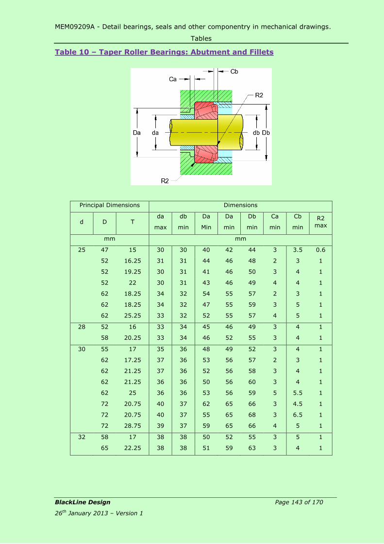
MEM09209A - Detail bearings, seals and other componentry in mechanical drawings.
Tables
BlackLine Design Page 143 of 170
26th January 2013 – Version 1
Table 10 – Taper Roller Bearings: Abutment and Fillets
Principal Dimensions Dimensions
d D T da
max
db
min
Da
Min
Da
min
Db
min
Ca
min
Cb
min
R2 max
mm mm
25 47 15 30 30 40 42 44 3 3.5 0.6
52 16.25 31 31 44 46 48 2 3 1
52 19.25 30 31 41 46 50 3 4 1
52 22 30 31 43 46 49 4 4 1
62 18.25 34 32 54 55 57 2 3 1
62 18.25 34 32 47 55 59 3 5 1
62 25.25 33 32 52 55 57 4 5 1
28 52 16 33 34 45 46 49 3 4 1
58 20.25 33 34 46 52 55 3 4 1
30 55 17 35 36 48 49 52 3 4 1
62 17.25 37 36 53 56 57 2 3 1
62 21.25 37 36 52 56 58 3 4 1
62 21.25 36 36 50 56 60 3 4 1
62 25 36 36 53 56 59 5 5.5 1
72 20.75 40 37 62 65 66 3 4.5 1
72 20.75 40 37 55 65 68 3 6.5 1
72 28.75 39 37 59 65 66 4 5 1
32 58 17 38 38 50 52 55 3 5 1
65 22.25 38 38 51 59 63 3 4 1
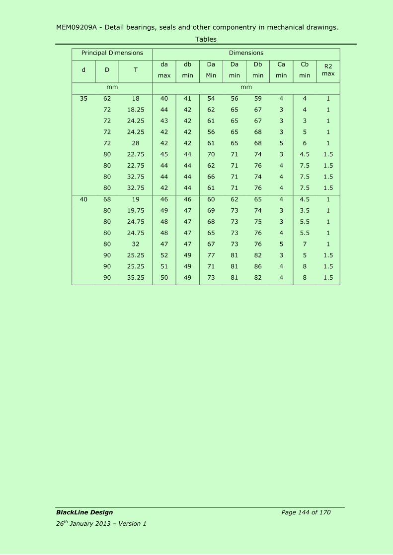
MEM09209A - Detail bearings, seals and other componentry in mechanical drawings.
Tables
BlackLine Design Page 144 of 170
26th January 2013 – Version 1
Principal Dimensions Dimensions
d D T da
max
db
min
Da
Min
Da
min
Db
min
Ca
min
Cb
min
R2 max
mm mm
35 62 18 40 41 54 56 59 4 4 1
72 18.25 44 42 62 65 67 3 4 1
72 24.25 43 42 61 65 67 3 3 1
72 24.25 42 42 56 65 68 3 5 1
72 28 42 42 61 65 68 5 6 1
80 22.75 45 44 70 71 74 3 4.5 1.5
80 22.75 44 44 62 71 76 4 7.5 1.5
80 32.75 44 44 66 71 74 4 7.5 1.5
80 32.75 42 44 61 71 76 4 7.5 1.5
40 68 19 46 46 60 62 65 4 4.5 1
80 19.75 49 47 69 73 74 3 3.5 1
80 24.75 48 47 68 73 75 3 5.5 1
80 24.75 48 47 65 73 76 4 5.5 1
80 32 47 47 67 73 76 5 7 1
90 25.25 52 49 77 81 82 3 5 1.5
90 25.25 51 49 71 81 86 4 8 1.5
90 35.25 50 49 73 81 82 4 8 1.5

MEM09209A - Detail bearings, seals and other componentry in mechanical drawings.
Tables
BlackLine Design Page 145 of 170
26th January 2013 – Version 1
Table 11 – Wiper Seals
Metal Cased Wiper
D-Style Rod Wiper
Metal Cased Rod Wiper D – Style Rod Wiper
Prod. Code
Ref No.
A B C
Prod. Code
Ref No.
A B C D E
h10 ±0.05 +0.12
-0.00 h10 +0.12
-0.00
+0.15
-0.000
+0.15
-0.000 Nom.
R26000 J0400 8 13 4.15 RD0500 D0500 8 12.45 3.15 10.00 5.33
R26001 J0450 10 16 6.35 RD0625 D0625 10 15.95 3.15 13.50 5.33
R26002 J0500 12 20 6.35 RD0750 D0750 12 18.97 3.15 16.75 5.33
R26003 J0625 15 26 8.15 RD1000 D1000 15 22.14 3.15 19.00 5.33
R26004 J0750 20 32 8.15 RD1250 D1250 20 28.50 4.75 25.25 7.75
R26005 J0875 22 35 8.15 RD1375 D1375 25 34.85 4.75 31.50 7.75
R26006 J1000 25 38 8.15 RD1500 D1500 32 41.20 4.75 38.00 7.75
R26007 J1125 28 42 8.15 RD1625 D1625 35 44.37 4.75 41.15 7.75
R26008 J1250 32 45 8.15 RD1750 D1750 38 47.55 4.75 44.25 7.75
R26009 J1375 35 48 8.15 RD1875 D1875 42 50.72 4.75 47.50 7.75
R26010 J1500 38 50 8.15 RD2000 D2000 45 53.90 4.75 50.50 7.75
R26011 J1625 42 54 8.15 RD2250 D2250 48 57.07 4.75 53.85 7.75
R26012 J1750 45 58 8.15 RD2500 D2500 50 63.42 6.32 59.00 10.03
R26013 J1875 48 60 8.15 RD2750 D2750 58 69.77 6.32 65.50 10.03
R26014 J2000 50 64 8.15 RD3000 D3000 64 76.12 6.32 71.75 10.03
R26015 J2125 54 66 8.15 RD3250 D3250 70 82.47 6.32 78.00 10.03
R26016 J2250 58 70 8.15 RD3500 D3500 75 88.82 6.32 84.50 10.03
R26017 J2375 60 72 8.15 RD3700 D3700 80 95.17 6.32 90.75 10.03

MEM09209A - Detail bearings, seals and other componentry in mechanical drawings.
Tables
BlackLine Design Page 146 of 170
26th January 2013 – Version 1
Metal Cased Rod Wiper
Prod. Code
Ref No.
A B C
h10 ±0.05 +0.12
-0.00
R26018 J2500 64 75 8.15
R26020 J2625 66 80 8.15
R26022 J2750 70 82 8.15
R26024 J3000 75 88 8.15
R26027 J3250 82 98 8.15
R26028 J3500 88 105 8.15
R26029 J4000 100 118 8.15
R26030 J4500 115 130 8.15
R26031 J5000 125 142 8.15

MEM09209A - Detail bearings, seals and other componentry in mechanical drawings.
Tables
BlackLine Design Page 147 of 170
26th January 2013 – Version 1
Table 12 – Rod Seals
Prod Code
Part No. A a
H10
B b
H10
C c
Nom.
D
+0.25
-0.000
R00274 SU1 8 4 4.76 5.35
R00275 SU2 10 6 4.76 5.35
R00276 SU3 11 7.50 4.76 5.35
R00277 SU4 12 8.50 4.75 5.35
R00278 SU5 13 9.50 4.75 5.35
R00279 SU6 14 10 4.75 5.35
R00280 SU7 15 11 4.75 5.35
R00281 SU8 16 12 6.35 7.00
R00282 SU9 17 13 6.35 7.00
R00283 SU10 18 13.5 6.35 7.00
R00284 SU11 19 14.5 6.35 7.00
R00285 SU12 20 15.5 6.35 7.00
R00286 SU13 22 17.5 6.35 7.00
R00287 SU14 24 18 6.35 7.00
R00288 SU15 25 19 6.35 7.00
R00289 SU16 26 20 6.35 7.00
R00290 SU17 28 22 6.35 7.00
R00291 SU18 30 24 6.35 7.00
R00292 SU19 32 25.5 6.35 7.00
R00293 SU20 34 27.5 6.35 7.00
R00294 SU21 36 29.5 6.35 7.00
R00295 SU22 38 31.5 6.35 7.00
R00296 SU23 40 33 6.35 7.00
R00297 SU24 42 35 6.35 7.00

MEM09209A - Detail bearings, seals and other componentry in mechanical drawings.
Tables
BlackLine Design Page 148 of 170
26th January 2013 – Version 1
Prod Code Part No.
A a
H10 B b
H10
C c
Nom.
D
+0.25
-0.000
R00298 SU25 44 37 7.95 9.50
R00299 SU26 46 39 7.95 9.50
R00300 SU27 48 41 7.95 9.50
R00397 SU28 50 42.5 7.95 9.50
R00398 SU29 55 44.5 7.95 9.50
R00399 SU30 60 50 7.95 9.50
R00453 SU31 65 55 7.95 9.50
R00454 SU32 70 65 7.95 9.50
R00455 SU33 75 70 7.95 9.50
R00456 SU34 80 75 7.95 9.50
R00457 SU35 85 80 7.95 9.50
R00458 SU36 90 85 9.55 10.16
R00459 SU37 95 90 9.55 10.16
R00460 SU38 100 95 9.55 10.16

MEM09209A - Detail bearings, seals and other componentry in mechanical drawings.
Tables
BlackLine Design Page 149 of 170
26th January 2013 – Version 1
Table 13 – Piston Ring
Prof Code Ref No. A
H9
B
h10
C
+0.25
-0.00
D
+0.00
-0.05
E
+0.05
-0.00
F
+0.05
-0.05
RZLD01 LD01-WRN 10 8 10 3 7.5 9.5
RZLD02 LD02-WRN 12 9 10 3 9.5 11.5
RZLD03 LD03-WRN 14 10 12 4 11 13.5
RZLD04 LD04-WRN 16 11 12 4 13 15.25
RZLD05 LD05-WRN 18 12 12 4 15 17.25
RZLD06 LD06-WRN 20 13 14 4 17 19.25
RZLD07 LD07-WRN 22 14 14 4 19 21.25
RZLD08 LD08-WRN 24 15 14 6 21 23
RZLD09 LD09-WRN 25 16 14 6 21.5 24
RZLD10 LD10-WRN 26 17 16 6 22.5 25
RZLD11 LD11-WRN 28 18 16 6 24.5 27
RZLD13 LD13-WRN 30 19 16 6 26.5 29
RZLD15 LD15-WRN 32 20 16 6 28.5 30.75
RZLD17 LD17-WRN 38 25 16 8 34 36.75
RZLD19 LD19-WRN 44 28 18 8 39 42.75
RZLD21 LD21-WRN 50 35 18 8 45 48.75
RZLD23 LD23-WRN 60 42 18 8 52 58
RZLD25 LD25-WRN 65 48 18 8 58 63
RZLD27 LD27-WRN 70 50 20 8 62 68
RZLD29 LD29-WRN 75 55 20 8 69 73

MEM09209A - Detail bearings, seals and other componentry in mechanical drawings.
Tables
BlackLine Design Page 150 of 170
26th January 2013 – Version 1
Prof Code Ref No. A
H9
B
h10
C
+0.25
-0.00
D
+0.00
-0.05
E
+0.05
-0.00
F
+0.05
-0.05
RZLD31 LD31-WRN 80 60 20 8 75 78
RZLD32 LD32-WRN 90 70 20 8 82 88
RZLD34 LD34-WRN 100 80 20 8 94 98
RZLD36 LD36-WRN 120 90 25 10 107 118
RZLD38 LD38-WRN 130 100 25 10 120 128
RZLD40 LD40-WRN 140 120 25 10 132 138
RZLD42 LD42-WRN 150 130 25 10 145 148

MEM09209A - Detail bearings, seals and other componentry in mechanical drawings.
Tables
BlackLine Design Page 151 of 170
26th January 2013 – Version 1
Table 14 – Guide or Wear Ring
WR/J & JWR Wear Rings
Prod. Code
Reference No.
A
H9
B
+0.02
-0.02
C
+0.25
-0.00
D
+0.50
-0.00
R10979 060 WR/J 5 4 4.75 0.50
R10980 065 WR/J 8 6.5 4.75 0.75
R10981 070 WR/J 10 8.5 4.75 0.75
R10982 075 WR/J 12 9.5 4.75 1.25
R10983 080 WR/J 14 11.5 4.75 1.25
R10984 085 WR/J 16 13.5 4.75 1.25
R10985 090 WR/J 18 14 4.75 2.00
R10986 095 WR/J 20 16 4.75 2.00
R10987 098 WR/J 22 18 4.75 2.00
R10988 100 WR/J 25 20 6.35 2.50
R10989 112 WR/J 28 23.5 6.35 2.25
R10990 125 WR/J 30 26 6.35 2.00
R10991 137 WR/J 34 29.5 6.35 2.50
R10992 150 WR/J 38 33 9.53 2.50
R10993 162 WR/J 42 36.5 9.53 2.75
R10994 175 WR/J 44 38.5 9.53 2.75
R10995 187 WR/J 48 42 9.53 3.00
R10996 200 WR/J 50 46 9.53 3.00
R10997 212 WR/J 54 48 9.53 3.00
R10998 225 WR/J 58 52 9.53 3.00
R10999 237 WR/J 60 55 9.53 2.50
R11000 250 WR/J 64 58 9.53 3.00
R11001 262 WR/J 66 61 9.53 2.50
R11002 275 WR/J 70 65 9.53 2.50
R11003 287 WR/J 72 68 9.53 2.50

MEM09209A - Detail bearings, seals and other componentry in mechanical drawings.
Tables
BlackLine Design Page 152 of 170
26th January 2013 – Version 1
Prod.
Code
Reference
No.
A
H9
B
+0.02 -0.02
C
+0.25 -0.00
D
+0.50 -0.00
R11004 300 WR/J 75 71 9.53 2.00
R11005 310 WR/J 78 73 9.53 2.50
R11006 312 WR/J 80 74 9.53 3.00
R11007 318 WR/J 82 76 9.53 3.00
R11008 325 WR/J 85 77 9.53 4.00
R11009 350 WR/J 90 83 9.53 3.50
R11010 375 WR/J 92 85 12.70 3.50
R11011 400 WR/J 95 88 12.70 3.50
R11012 425 WR/J 100 92 12.70 4.00
R11013 450 WR/J 102 94 12.70 4.00
R11014 462 WR/J 105 97 12.70 4.00
R11015 475 WR/J 108 100 12.70 4.00
R11016 500 WR/J 110 102 12.70 4.00
R11017 525 WR/J 115 106 12.70 4.50
R11018 550 WR/J 118 109 12.70 4.50
R11019 575 WR/J 120 111 12.70 4.50
R11020 600 WR/J 125 116 12.70 4.50

MEM09209A - Detail bearings, seals and other componentry in mechanical drawings.
Tables
BlackLine Design Page 153 of 170
26th January 2013 – Version 1
Table 15 – Vee Packing Seals
Stack Height = B/A + VEE x Number Required + T/A
Product Code
Ref.
No.
A
H9
B
e9
C
Nom
D
+0.00
-0.15
Product Code
Ref.
No.
A
H9
B
e9
C
Nom
D
+0.00
-0.15
R00100 VEE 10 20 2.20 11.00 R00729 T/A 50 70 12.70 48.25
R00106 T/A 10 20 2.45 11.00 R00535 VEE 50 70 6.35 48.25
R00109 B/A 10 20 2.85 11.00 R00880 B/A 50 70 3.18 48.25
R00205 VEE 12 28 2.75 13.00 R00720 T/A 50 64 6.35 48.25
R00207 T/A 12 28 2.89 13.00 R00536 VEE 52 75 3.96 53.50
R00303 B/A 12 28 3.00 13.00 R00727 T/A 55 70 7.95 56.75
R00305 VEE 15 29 3.47 16.00 R00533 VEE 55 70 3.96 56.75
R00403 T/A 15 29 3.89 16.00 R00878 B/A 55 70 1.60 56.75
R00406 B/A 15 29 3.50 16.00 R00537 VEE 58 72 5.16 56.75
R00501 VEE 18 30 3.96 19.00 R00728 T/A 58 70 6.35 59.80
R00502 VEE 18 30 3.18 19.00 R00534 VEE 58 70 3.28 59.80
R00700 T/A 18 30 6.35 19.00 R06258 B/A 58 72 1.60 59.80
R00850 B/A 20 31 1.60 21.25 R00731 T/A 58 76 9.53 59.80
R00504 VEE 20 31 2.54 21.25 R00732 T/A 58 76 12.70 59.80
R00701 T/A 20 31 4.77 21.25 R00541 VEE 58 76 4.78 59.80
R00503 VEE 22 32 2.39 23.25 R00882 B/A 58 76 1.60 59.80
R00851 B/A 22 32 2.39 23.25 R00883 B/A 58 76 4.78 59.80
R00702 T/A 22 35 6.35 23.25 R00735 T/A 58 76 6.81 59.80
R00505 VEE 22 35 3.18 23.25 R00547 VEE 58 76 3.96 59.80
R00852 B/A 22 35 1.60 23.25 R00886 B/A 58 76 1.60 59.80
R00703 T/A 24 36 6.35 25.15 R00879 B/A 58 70 1.60 59.80
R00506 VEE 24 36 3.18 25.15 R00538 VEE 58 72 3.96 59.80
R00853 B/A 24 36 1.60 25.15 R06246 T/A 58 72 7.92 59.80
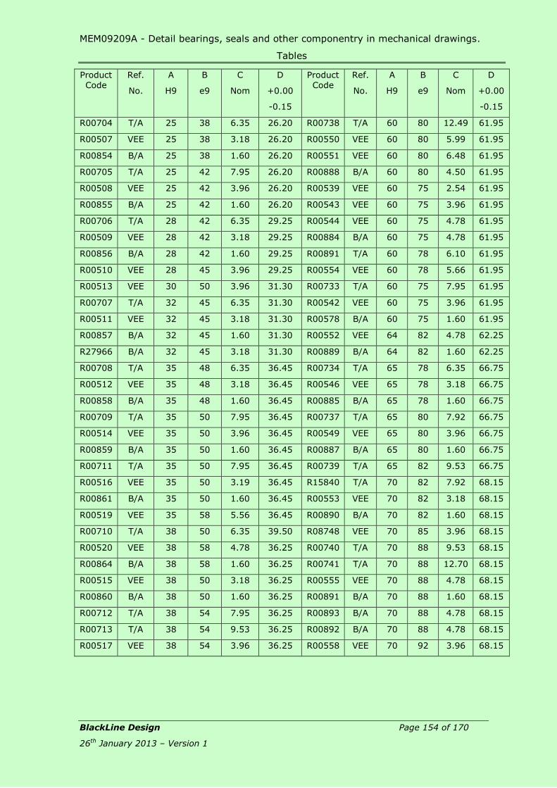
MEM09209A - Detail bearings, seals and other componentry in mechanical drawings.
Tables
BlackLine Design Page 154 of 170
26th January 2013 – Version 1
Product
Code
Ref.
No.
A
H9
B
e9
C
Nom
D
+0.00
-0.15
Product
Code
Ref.
No.
A
H9
B
e9
C
Nom
D
+0.00
-0.15
R00704 T/A 25 38 6.35 26.20 R00738 T/A 60 80 12.49 61.95
R00507 VEE 25 38 3.18 26.20 R00550 VEE 60 80 5.99 61.95
R00854 B/A 25 38 1.60 26.20 R00551 VEE 60 80 6.48 61.95
R00705 T/A 25 42 7.95 26.20 R00888 B/A 60 80 4.50 61.95
R00508 VEE 25 42 3.96 26.20 R00539 VEE 60 75 2.54 61.95
R00855 B/A 25 42 1.60 26.20 R00543 VEE 60 75 3.96 61.95
R00706 T/A 28 42 6.35 29.25 R00544 VEE 60 75 4.78 61.95
R00509 VEE 28 42 3.18 29.25 R00884 B/A 60 75 4.78 61.95
R00856 B/A 28 42 1.60 29.25 R00891 T/A 60 78 6.10 61.95
R00510 VEE 28 45 3.96 29.25 R00554 VEE 60 78 5.66 61.95
R00513 VEE 30 50 3.96 31.30 R00733 T/A 60 75 7.95 61.95
R00707 T/A 32 45 6.35 31.30 R00542 VEE 60 75 3.96 61.95
R00511 VEE 32 45 3.18 31.30 R00578 B/A 60 75 1.60 61.95
R00857 B/A 32 45 1.60 31.30 R00552 VEE 64 82 4.78 62.25
R27966 B/A 32 45 3.18 31.30 R00889 B/A 64 82 1.60 62.25
R00708 T/A 35 48 6.35 36.45 R00734 T/A 65 78 6.35 66.75
R00512 VEE 35 48 3.18 36.45 R00546 VEE 65 78 3.18 66.75
R00858 B/A 35 48 1.60 36.45 R00885 B/A 65 78 1.60 66.75
R00709 T/A 35 50 7.95 36.45 R00737 T/A 65 80 7.92 66.75
R00514 VEE 35 50 3.96 36.45 R00549 VEE 65 80 3.96 66.75
R00859 B/A 35 50 1.60 36.45 R00887 B/A 65 80 1.60 66.75
R00711 T/A 35 50 7.95 36.45 R00739 T/A 65 82 9.53 66.75
R00516 VEE 35 50 3.19 36.45 R15840 T/A 70 82 7.92 68.15
R00861 B/A 35 50 1.60 36.45 R00553 VEE 70 82 3.18 68.15
R00519 VEE 35 58 5.56 36.45 R00890 B/A 70 82 1.60 68.15
R00710 T/A 38 50 6.35 39.50 R08748 VEE 70 85 3.96 68.15
R00520 VEE 38 58 4.78 36.25 R00740 T/A 70 88 9.53 68.15
R00864 B/A 38 58 1.60 36.25 R00741 T/A 70 88 12.70 68.15
R00515 VEE 38 50 3.18 36.25 R00555 VEE 70 88 4.78 68.15
R00860 B/A 38 50 1.60 36.25 R00891 B/A 70 88 1.60 68.15
R00712 T/A 38 54 7.95 36.25 R00893 B/A 70 88 4.78 68.15
R00713 T/A 38 54 9.53 36.25 R00892 B/A 70 88 4.78 68.15
R00517 VEE 38 54 3.96 36.25 R00558 VEE 70 92 3.96 68.15

MEM09209A - Detail bearings, seals and other componentry in mechanical drawings.
Tables
BlackLine Design Page 155 of 170
26th January 2013 – Version 1
Product
Code
Ref.
No.
A
H9
B
e9
C
Nom
D
+0.00
-0.15
Product
Code
Ref.
No.
A
H9
B
e9
C
Nom
D
+0.00
-0.15
R00862 B/A 38 54 1.60 36.25 R00743 T/A 70 90 9.53 68.15
R00863 B/A 38 54 3.96 36.25 R00557 VEE 70 90 4.78 68.15
R00714 T/A 38 58 9.53 36.25 R00895 B/A 70 90 1.60 68.15
R00518 VEE 41 58 3.18 39.40 R00560 VEE 72 96 6.35 70.25
R00715 T/A 45 58 6.35 43.20 R00742 T/A 76 88 6.35 74.15
R00521 VEE 45 58 3.18 43.20 R00556 VEE 76 88 3.18 74.15
R00865 B/A 45 58 1.60 43.20 R00894 B/A 76 88 1.60 74.15
R00522 VEE 45 58 3.18 43.20 R00744 T/A 76 92 9.53 74.15
R00716 T/A 45 60 7.95 43.20 R00559 VEE 76 92 4.78 74.15
R00523 VEE 45 60 3.96 43.20 R00896 B/A 79 92 1.60 74.15
R00866 B/A 45 60 1.60 43.20 R00564 VEE 80 102 5.56 78.20
R00717 T/A 45 65 9.53 43.20 R00561 VEE 82 98 3.96 80.25
R00524 VEE 45 65 4.78 43.20 R00745 T/A 80 98 11.13 78.20
R00867 B/A 45 65 1.60 43.20 R00897 B/A 82 98 3.18 78.20
R00724 T/A 45 65 12.70 43.20 R00750 T/A 82 102 8.33 80.25
R00531 VEE 45 65 6.35 43.20 R00749 T/A 82 102 15.88 80.25
R00875 B/A 45 65 1.60 43.20 R00570 VEE 82 102 4.78 80.25
R01296 VEE 45 65 5.99 43.20 R00901 B/A 82 102 1.60 80.25
R00722 T/A 45 65 12.70 43.20 R00563 VEE 82 98 4.37 80.25
R00528 VEE 45 65 4.78 43.20 R00746 T/A 82 102 9.53 80.25
R00873 B/A 45 65 1.60 43.20 R00747 T/A 82 102 12.70 80.25
R00718 T/A 48 65 7.95 46.20 R00565 VEE 82 102 4.78 80.25
R00719 T/A 48 65 9.53 46.20 R00989 B/A 82 102 1.60 80.25
R00525 VEE 48 65 3.96 46.20 R00899 B/A 82 102 4.78 80.25
R00868 B/A 48 65 1.60 46.20 R00587 VEE 82 102 10.30 80.25
R00869 B/A 48 65 3.96 46.20 R00566 VEE 86 102 4.78 84.15
R00721 T/A 48 64 7.37 46.20 R00567 VEE 86 102 3.96 84.15
R00527 VEE 48 64 3.96 46.20 R00568 VEE 86 102 4.78 84.15
R00872 B/A 48 64 1.60 46.20 R00900 B/A 86 102 4.78 84.15
R00526 VEE 50 62 3.18 51.50 R00938 B/A 86 102 1.60 84.15
R00870 B/A 50 62 1.60 51.50 R00748 T/A 88 102 6.35 86.10
R00871 B/A 50 62 3.08 51.50 R00569 VEE 88 102 3.18 86.10
R00796 T/A 50 66 6.35 51.50 R01100 B/A 88 102 4.75 86.10
R00797 T/A 50 66 7.37 51.50 R00752 T/A 88 108 9.53 86.10

MEM09209A - Detail bearings, seals and other componentry in mechanical drawings.
Tables
BlackLine Design Page 156 of 170
26th January 2013 – Version 1
Product
Code
Ref.
No.
A
H9
B
e9
C
Nom
D
+0.00
-0.15
Product
Code
Ref.
No.
A
H9
B
e9
C
Nom
D
+0.00
-0.15
R00723 T/A 50 66 7.95 51.50 R00573 VEE 88 108 4.78 86.10
R00798 T/A 50 66 9.53 51.50 R00903 B/A 88 108 1.60 86.10
R00529 VEE 50 66 3.96 51.50 R00753 T/A 88 115 12.78 86.10
R00874 B/A 50 66 1.60 51.50 R00754 T/A 88 115 15.88 86.10
R00530 VEE 50 66 4.78 51.50 R00575 VEE 88 115 6.35 86.10
R00725 T/A 50 70 9.53 51.50 R00904 B/A 88 115 1.60 86.10
R00726 T/A 50 70 12.70 51.50 R00905 B/A 88 115 9.53 86.10
R00532 VEE 50 70 4.78 51.50 R00588 VEE 88 124 8.74 86.10
R00876 B/A 50 70 1.60 51.50 R00757 T/A 90 115 12.19 88.00
R00877 B/A 50 70 4.78 51.50 R00578 VEE 90 115 6.35 88.00
R00730 T/A 50 75 12.70 51.50
R00540 VEE 50 75 6.35 51.50
R00881 B/A 50 75 1.60 51.50

MEM09209A - Detail bearings, seals and other componentry in mechanical drawings.
Tables
BlackLine Design Page 157 of 170
26th January 2013 – Version 1
Table 16 – O-Rings Standard Groove Types for Hydraulic Service
Piston
Gland
Face (No BTU Req’d)
Triangular
Groove Design & Surface Finish
SF Static Dynamic
BUW’s NO BUW’s
x y z x y z x y z
µm 0.8 1.6 0.8 0.8 1.6 0.4 0.8 0.8 0.4
CS
Cross Section
0.20 H 0.00 A R G F
Groove Depth Groove Width
Dynamic Static No. of BUW’s +0.12
-0.00
Groove Radius
Diam’l Clear
Lead In
mm Inch Max Min Max Min 0 1 2 Max Max Min
1.00 0.85 0.80
1.50 1.30 1.25
1.60 1.38 1.33
1.78 1/16 1.53 1.47
1.90 1.64 1.59
2.00 1.74 1.69
2.40 2.13 2.07
2.50 2.23 2.18
2.62 3/32 2.34 2.25
3.00 2.71 2.64
3.10 2.81 2.69
3.50 3.21 3.09
3.53 1/8 3.21 3.09
4.00 3.66 3.54
5.00 4.60 4.40
5.33 3/16 4.86 4.70
5.70 5.28 5.08
6.00 5.50 5.30
6.99 1/4 6.31 6.11
8.40 7.75 7.55

MEM09209A - Detail bearings, seals and other componentry in mechanical drawings.
Tables
BlackLine Design Page 158 of 170
26th January 2013 – Version 1
0.20 H 0.00 A R G F
Groov
e
Radius
Diam'l
Clear
Lead
In
mm Inch Max Min Max Min 0 1 2 Max Max Min
1.00 0.85 0.80 0.75 0.70 1.30 - - 1.40 0.25 0.10 1.00
1.50 1.30 1.25 1.20 1.15 1.95 - - 2.00 0.25 0.10 1.00
1.60 1.38 1.33 1.28 1.23 2.08 - - 2.20 0.38 0.10 1.00
1.78 1/16 1.53 1.47 1.38 1.33 2.34 4.10 6.10 2.40 0.38 0.13 1.00
1.90 1.64 1.59 1.53 1.48 2.57 4.10 6.00 2.65 0.38 0.13 1.50
2.00 1.74 1.69 1.60 1.55 2.60 - - 2.70 0.38 0.13 1.50
2.40 2.13 2.07 1.92 1.87 3.12 4.60 6.00 3.20 0.38 0.13 1.50
2.50 2.23 2.18 2.00 1.95 3.25 - - 3.40 0.38 0.13 1.50
2.62 3/32 2.34 2.25 2.08 2.03 3.38 4.60 6.50 3.50 0.38 0.13 1.50
3.00 2.71 2.64 2.50 2.30 3.90 5.40 6.80 4.00 0.63 0.13 2.00
3.10 2.81 2.69 2.52 2.32 4.00 5.50 6.90 4.10 0.63 0.13 2.00
3.50 3.21 3.09 2.90 2.70 4.55 6.10 7.50 4.80 0.63 0.13 2.00
3.53 1/8 3.21 3.09 2.90 2.70 4.55 5.50 7.40 4.80 0.63 0.15 2.00
4.00 3.66 3.54 3.30 3.10 5.20 - - 5.40 0.63 0.15 3.00
5.00 4.60 4.40 4.15 3.85 6.50 - - 6.70 0.63 0.15 3.00
5.33 3/16 4.86 4.70 4.42 4.12 6.95 7.60 10.20 7.15 0.89 0.15 3.00
5.70 5.28 5.08 4.75 4.45 7.47 9.30 11.10 7.70 0.89 0.15 4.00
6.00 5.50 5.30 4.95 4.65 7.80 - - 8.00 0.89 0.15 4.00
6.99 1/4 6.31 6.11 5.78 5.45 9.10 10.05 13.50 9.40 0.89 0.17 4.00
8.40 7.75 7.55 6.95 6.65 11.05 13.20 15.40 11.40 0.89 0.17 4.00
+0.12
-0.00
CS
Cross
Section
Groove Depth Groove Width
Dynamic Static No. of BUW's
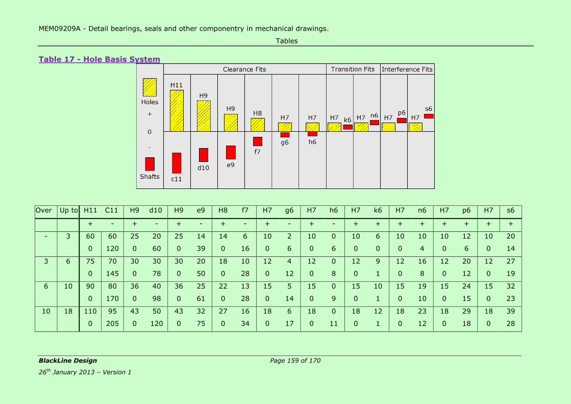
MEM09209A - Detail bearings, seals and other componentry in mechanical drawings.
Tables
BlackLine Design Page 159 of 170
26th January 2013 – Version 1
Table 17 - Hole Basis System
Over Up to H11 C11 H9 d10 H9 e9 H8 f7 H7 g6 H7 h6 H7 k6 H7 n6 H7 p6 H7 s6
+ - + - + - + - + - + - + + + + + + + +
- 3 60 60 25 20 25 14 14 6 10 2 10 0 10 6 10 10 10 12 10 20
0 120 0 60 0 39 0 16 0 6 0 6 0 0 0 4 0 6 0 14
3 6 75 70 30 30 30 20 18 10 12 4 12 0 12 9 12 16 12 20 12 27
0 145 0 78 0 50 0 28 0 12 0 8 0 1 0 8 0 12 0 19
6 10 90 80 36 40 36 25 22 13 15 5 15 0 15 10 15 19 15 24 15 32
0 170 0 98 0 61 0 28 0 14 0 9 0 1 0 10 0 15 0 23
10 18 110 95 43 50 43 32 27 16 18 6 18 0 18 12 18 23 18 29 18 39
0 205 0 120 0 75 0 34 0 17 0 11 0 1 0 12 0 18 0 28

MEM09209A - Detail bearings, seals and other componentry in mechanical drawings.
Tables
BlackLine Design Page 160 of 170
26th January 2013 – Version 1
Over Up to H11 C11 H9 d10 H9 e9 H8 f7 H7 g6 H7 h6 H7 k6 H7 n6 H7 p6 H7 s6
+ - + - + - + - + - + - + + + + + + + +
18 30 130 110 52 65 52 40 33 20 21 7 21 0 21 15 21 28 21 35 21 48
0 240 0 149 0 92 0 41 0 20 0 13 0 2 0 15 0 22 0 35
30 40 120
160 280 62 80 62 50 39 25 25 9 25 0 25 18 25 33 25 42 25 59
40 50 0 130 0 180 0 112 0 50 0 25 0 16 0 2 0 17 0 26 0 43
290
50 65 140 72
190 330 74 100 74 60 46 30 30 10 30 0 30 21 30 39 30 51 30 53
65 80 0 150 0 220 0 134 0 60 0 29 0 19 0 2 0 20 0 32 0 78
340 59
80 100 170 93
220 390 87 120 87 72 54 36 35 12 35 0 35 26 35 45 35 59 35 71
100 120 0 180 0 260 0 159 0 71 0 34 0 22 0 3 0 23 0 37 0 101
400 79
120 140 200 117
450 92
140 160 250 210 100 145 100 84 63 43 40 14 40 0 40 28 40 52 40 68 40 125
0 460 0 305 0 185 0 83 0 39 0 25 0 3 0 27 0 43 0 100
160 180 230 133
480 108
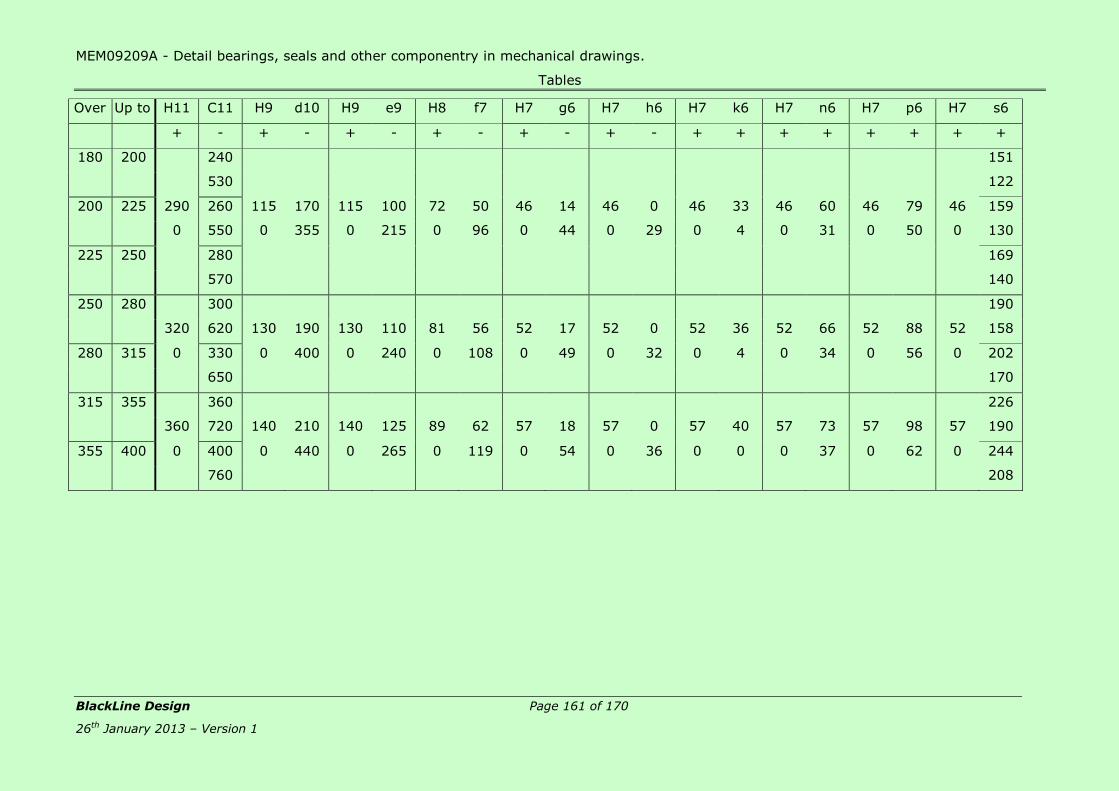
MEM09209A - Detail bearings, seals and other componentry in mechanical drawings.
Tables
BlackLine Design Page 161 of 170
26th January 2013 – Version 1
Over Up to H11 C11 H9 d10 H9 e9 H8 f7 H7 g6 H7 h6 H7 k6 H7 n6 H7 p6 H7 s6
+ - + - + - + - + - + - + + + + + + + +
180 200 240 151
530 122
200 225 290 260 115 170 115 100 72 50 46 14 46 0 46 33 46 60 46 79 46 159
0 550 0 355 0 215 0 96 0 44 0 29 0 4 0 31 0 50 0 130
225 250 280 169
570 140
250 280 300 190
320 620 130 190 130 110 81 56 52 17 52 0 52 36 52 66 52 88 52 158
280 315 0 330 0 400 0 240 0 108 0 49 0 32 0 4 0 34 0 56 0 202
650 170
315 355 360 226
360 720 140 210 140 125 89 62 57 18 57 0 57 40 57 73 57 98 57 190
355 400 0 400 0 440 0 265 0 119 0 54 0 36 0 0 0 37 0 62 0 244
760 208

MEM09209A - Detail bearings, seals and other componentry in mechanical drawings.
Tables
BlackLine Design Page 162 of 170
26th January 2013 – Version 1
Table 18 – Shaft Basis System
Over Up to C11 h11 D10 h9 E9 h9 F8 h7 G7 h6 H7 h6 K7 h6 N7 h6 P7 h6 S7 h6
+ - + - + - + - + - + - +&- - - - - - - -
- 3 120 0 60 0 39 0 20 0 12 0 10 0 0 0 4 0 6 0 14 0
60 60 20 25 14 25 6 10 2 6 0 6 -10 6 14 6 16 6 24 6
3 6 145 0 78 0 50 0 28 0 16 0 12 0 3 0 4 0 8 0 15 0
70 75 30 30 20 30 10 12 4 8 0 8 -9 8 16 8 2 8 27 8
6 10 170 0 98 0 61 0 35 0 20 0 15 0 5 0 4 0 9 0 17 0
80 90 40 36 25 36 13 15 5 9 0 9 -10 9 19 9 24 9 32 9
10 18 205 0 120 0 75 0 43 0 24 0 18 0 6 0 5 0 11 0 21 0
95 110 50 43 32 43 16 18 6 11 0 11 -12 11 23 11 29 11 39 11
18 30 240 0 149 0 92 0 53 0 28 0 21 0 6 0 7 0 14 0 27 0
110 130 65 52 40 52 20 21 7 13 0 13 -15 13 28 13 35 13 48 13

MEM09209A - Detail bearings, seals and other componentry in mechanical drawings.
Tables
BlackLine Design Page 163 of 170
26th January 2013 – Version 1
Over Up to C11 h11 D10 h9 E9 h9 F8 h7 G7 h6 H7 h6 K7 h6 N7 h6 P7 h6 S7 h6
30 40 280 0
120 160 180 0 112 0 64 0 34 0 25 0 7 0 8 0 17 0 34 0
40 50 290 0 80 62 50 62 25 25 9 16 0 16 -18 16 33 16 42 16 59 16
130 160
50 65 330 0 42 0
140 190 220 0 134 0 76 0 40 0 30 0 9 0 9 0 21 0 72 19
65 80 340 0 100 74 60 74 30 30 10 19 0 19 -21 19 39 19 51 19 48 0
150 190 78 19
80 100 390 0 58 0
170 220 260 0 159 0 90 0 47 0 35 0 10 0 10 0 24 0 93 22
100 120 400 0 120 87 72 87 36 35 12 22 0 22 -25 22 45 22 59 22 66 0
180 220 101 22
120 140 450 0 77 0
200 250 117 25
140 160 460 0 305 0 185 0 106 0 54 0 40 0 12 0 12 0 28 0 85 0
210 250 145 100 85 100 43 40 14 25 0 25 -28 25 52 25 68 25 125 25
160 180 480 0 93 0
230 250 133 25
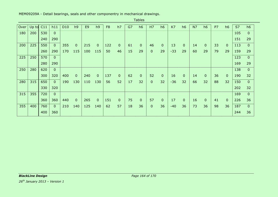
MEM09209A - Detail bearings, seals and other componentry in mechanical drawings.
Tables
BlackLine Design Page 164 of 170
26th January 2013 – Version 1
Over Up to C11 h11 D10 h9 E9 h9 F8 h7 G7 h6 H7 h6 K7 h6 N7 h6 P7 h6 S7 h6
180 200 530 0 105 0
240 290 151 29
200 225 550 0 355 0 215 0 122 0 61 0 46 0 13 0 14 0 33 0 113 0
260 290 170 115 100 115 50 46 15 29 0 29 -33 29 60 29 79 29 159 29
225 250 570 0 123 0
280 290 169 29
250 280 620 0 138 0
300 320 400 0 240 0 137 0 62 0 52 0 16 0 14 0 36 0 190 32
280 315 650 0 190 130 110 130 56 52 17 32 0 32 -36 32 66 32 88 32 150 0
330 320 202 32
315 355 720 0 169 0
360 360 440 0 265 0 151 0 75 0 57 0 17 0 16 0 41 0 226 36
355 400 760 0 210 140 125 140 62 57 18 36 0 36 -40 36 73 36 98 36 187 0
400 360 244 36
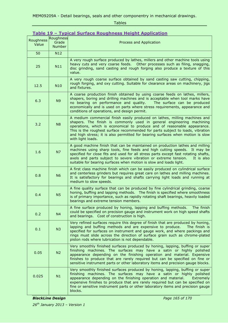
MEM09209A - Detail bearings, seals and other componentry in mechanical drawings.
Tables
BlackLine Design Page 165 of 170
26th January 2013 – Version 1
Table 19 – Typical Surface Roughness Height Application
Roughness Value
Roughness Grade
Number Process and Application
50 N12
25
N11
A very rough surface produced by lathes, millers and other machine tools using heavy cuts and very coarse feeds. Other processes such as filing, snagging, disc grinding, sand casting and rough forging also produce a texture of this value.
12.5
N10
A very rough coarse surface obtained by sand casting saw cutting, chipping, rough forging, and oxy cutting. Suitable for clearance areas on machinery, jigs and fixtures.
6.3
N9
A coarse production finish obtained by using coarse feeds on lathes, millers, shapers, boring and drilling machines and is acceptable when tool marks have
no bearing on performance and quality. The surface can be produced
economically and is used on parts where stress requirements, appearance and conditions of operations, and design permit.
3.2
N8
A medium commercial finish easily produced on lathes, milling machines and shapers. The finish is commonly used in general engineering machining operations, which is economical to produce and of reasonable appearance.
This is the roughest surface recommended for parts subject to loads, vibration and high stress; it is also permitted for bearing surfaces when motion is slow with light loads.
1.6
N7
A good machine finish that can be maintained on production lathes and milling machines using sharp tools, fine feeds and high cutting speeds. It may be
specified for close fits and used for all stress parts except fast rotating shafts, axels and parts subject to severe vibration or extreme tension. It is also suitable for bearing surfaces when motion is slow and loads light.
0.8
N6
A first class machine finish which can be easily produced on cylindrical surface and centerless grinders but requires great care on lathes and milling machines. It is satisfactory for bearings and shafts carrying light loads and running at
medium to slow speeds.
0.4
N5
A fine quality surface that can be produced by fine cylindrical grinding, coarse honing, buffing and lapping methods. The finish is specified where smoothness is of primary importance, such as rapidly rotating shaft bearings, heavily loaded bearings and extreme tension members.
0.2
N4
A fine surface produced by honing, lapping and buffing methods. The finish could be specified on precision gauge and instrument work on high speed shafts and bearings. Cost of construction is high.
0.1
N3
Very refined surfaces require this degree of finish that are produced by honing, lapping and buffing methods and are expensive to produce. The finish is
specified for surfaces on instrument and gauge work, and where packings and rings must slide across the direction of surface grain such as chrome-plated piston rods where lubrication is not dependable.
0.05
N2
Very smoothly finished surfaces produced by honing, lapping, buffing or super finishing machines. The surfaces may have a satin or highly polished
appearance depending on the finishing operation and material. Expensive finishes to produce that are rarely required but can be specified on fine or sensitive instrument parts or other laboratory items and precision gauge blocks.
0.025
N1
Very smoothly finished surfaces produced by honing, lapping, buffing or super finishing machines. The surfaces may have a satin or highly polished appearance depending on the finishing operation and material. Extremely
expensive finishes to produce that are rarely required but can be specified on fine or sensitive instrument parts or other laboratory items and precision gauge blocks.

MEM09209A - Detail bearings, seals and other componentry in mechanical drawings.
Tables
BlackLine Design Page 166 of 170
26th January 2013 – Version 1
Process Roughness Average Ra – Micrometres um
50 25 12.5 6.3 3.2 1.6 0.8 0.4 0.2 0.1 0.05 0.025
Flame Cutting Snagging Sawing Planing, Shaping Drilling Chemical Milling Elect discharge
mach Milling Broaching Reaming Electron Beam Laser Electro-chemical Boring, Turning Barrel finishing Electrolytic grinding Roller burnishing Grinding Honing Electro-polish Polishing Lapping Superfinishing Sand casting Hot rolling Forging Perm mold casting Investment casting Extruding Cold rolling, drawing Die casting
The ranges shown above are typical of the processes listed.
Higher or lower values may be obtained under special conditions.
Key Average Application
Less frequent application

MEM09209A - Detail bearings, seals and other componentry in mechanical drawings.
Tables
BlackLine Design Page 167 of 170
26th January 2013 – Version 1
Table 20 – Lay Symbols Symbol Designation Example
=
Lay parallel to the line
representing the surface to which the symbol is applied.
T
Lay perpendicular to the line representing the surface to
which the symbol is applied.
X
Lay angular in both directions.
M
Lay multidirectional.
C
Lay approximately circular relative to the center of the surface to which the symbol is applied.
R
Lay approximately radial relative to the centre of the surface to which the surface is applied.
P
Lay nondirectional, pitted or protuberant.
P

MEM09209A - Detail bearings, seals and other componentry in mechanical drawings.
Tables
BlackLine Design Page 168 of 170
26th January 2013 – Version 1
Table 21 – Dimensions and Tolerances for Keyways
All dimensions are in millimetres
NOTE: The relations between shaft diameter and key section given above are for general
applications. The use of smaller key sections is permitted if suitable for the torque
transmitted. In cases such as stepped shafts when larger diameters are required, for
example to resist bending, and when fans, gears and impellers are fitted with a smaller
key than nominal, an unequal disposition of key in shaft with relation to the hub results.
Therefore, dimension d – t1 and d + t2 should be recalculated to maintain the h/2
relationship. The use of larger key sections is not permitted.

MEM09209A - Detail bearings, seals and other componentry in mechanical drawings.
Tables
BlackLine Design Page 169 of 170
26th January 2013 – Version 1
1 2 3 4 5 6 7 8 9 10 11 12 13 14 15
Shaft Key Keyway
nom dia
see note d
Tolerance for class of fit depth radius
Section
b x h
free normal close
shaft
t1
hub
t2 r
Width
x
thickness
nom shaft
(H9)
hub
(D10)
shaft
(N9)
Hub
(J9)*
shaft &
Hub
(F9)
Nom Tol nom tol max min
6 8 2 x 2 2 +0.025 +0.060 -0.004 +0.012 -0.006 1.2 1 0.16 0.08
8 10 3 x 3 3 0 +0.020 -0.029 -0.012 -0.031 1.8 1.4 0.16 0.08
10 12 4 x 4 4 +0.030 +0.078 0 +0.015
-0.015
-0.012 2.5 +0.1 1.8 +0.1 0.16 0.08
12 17 5 x 5 5 0 +0.030 -0.030 -0.042 3 0 2.3 0 0.25 0.16
17 22 6 x 6 6 3.5 2.8 0.25 0.16
22 30 8 x 7 8 +0.036 +0.098 0 +0.018 -0.015 4 3.3 0.25 0.16
30 38 10 x 8 10 0 +0.040 -0.036 -0.018 -0.051 5 3.3 0.40 0.25
38 44 12 x 8 12 5 3.3 0.40 0.25
44 50 14 x 9 14 +0.043 +0.120 0 +0.021 -0.018 5.5 3.8 0.40 0.25
50 58 16 x 10 16 0 +0.050 -0.043 -0.021 -0.061 6 +0.2 4.3 +0.2 0.40 0.25
58 65 18 x 11 18 7 0 4.4 0 0.40 0.25
65 75 20 x 12 20 7.5 4.9 0.60 0.40
75 85 22 x 14 22 +0.052 +0.149 0 +0.026 -0.022 9 5.4 0.60 0.40
85 95 25 x 14 25 0 +0.065 -0.052 -0.026 -0.074 9 5.4 0.60 0.40
95 110 28 x 16 28 10 6.4 0.60 0.40

MEM09209A - Detail bearings, seals and other componentry in mechanical drawings.
Tables
BlackLine Design Page 170 of 170
26th January 2013 – Version 1
1 2 3 4 5 6 7 8 9 10 11 12 13 14 15
Shaft Key Keyway
Tolerance for class of fit depth radius
nom dia
see note d
Section
b x h
free normal close
shaft
t1
hub
t2 r
Width
x thickness
nom shaft (H9)
hub (D10)
shaft (N9)
Hub (J9)*
shaft & Hub (F9)
Nom Tol nom tol max min
110 130 32 x 18 32 11 7.4 0.60 0.40
130 150 36 x 20 36 +0.062 +0.180 0 +0.031 -0.026 12 8.4 1.00 0.70
150 170 40 x 22 40 0 +0.080 -0.062 -0.031 -0.088 13 9.4 1.00 0.70
170 200 45 x 25 45 15 10.4 1.00 0.70
200 230 50 x 28 50 17 11.4 1.00 0.70
230 260 56 x 32 56 20 +0.3 12.4 +0.3 1.60 1.20
260 290 63 x 32 63 +0.074 +0.220 0 +0.037 -0.032 20 0 12.4 0 1.60 1.20
290 330 70 x 36 70 0 +0.100 -0.074 -0.037 -0.106 22 14.4 1.60 1.20
330 380 80 x 40 80 25 15.4 2.50 2.00
380 440 90 x 45 90 +0.087 +0.260 0 +0.043 -0.037 28 17.4 2.50 2.00
440 500 100 x 50 100 0 +0.120 -0.087 -0.043 -0.124 31 19.5 2.50 2.00