Melt processability of polytetrafluoroethylene: Effect of melt treatment on tensile deformation...
8
Melt Processability of Polytetrafluoroethylene: Effect of Melt Treatment on Tensile Deformation Mechanism Min Li, 1 Wei Zhang, 2 Chaosheng Wang, 1 Huaping Wang 1 1 College of Materials Science and Engineering, Donghua University, Shanghai 201620, China 2 School of Polymer Textile and Fiber Engineering, Georgia Institute of Technology, Atlanta, Georgia 30332 Received 18 January 2011; accepted 1 April 2011 DOI 10.1002/app.34625 Published online 19 August 2011 in Wiley Online Library (wileyonlinelibrary.com). ABSTRACT: It is widely accepted that the melt processi- bility of polytetrafluoroethylene (PTFE) is poor. In this arti- cle, a high-molecular-weight PTFE was extruded smoothly with a modified die; and critical shear rate could be raised to 4 s 1 , using a die with L/D (length to diameter) ratio of 200. Meanwhile, we compared the current PTFE fiber spin- ning method with melt spinning to investigate the effects of high-temperature treatment on the drawability of PTFE and found that the processing sequence could play a key role. The deformation imposed before or after the high-tempera- ture treatment could determine whether the fibrillation can be achieved continuously and effectively. Based on the experiment phenomenon, together with the results of differ- ential scanning calorimetry, X-ray diffraction, and scanning electron microscopy characterization, we proposed a model to describe the submicron structural change of PTFE during extension. From this model, the fundamental mechanism for the poor melt processibility of PTFE was elucidated. V C 2011 Wiley Periodicals, Inc. J Appl Polym Sci 123: 1667–1674, 2012 Key words: polytetrafluoroethylene; melt; processibility; extrusion; entanglement; drawability INTRODUCTION Because of its extreme chemical inertness, thermal stability, and many other desirable physical proper- ties, polytetrafluoroethylene (PTFE) has been widely used in applications, where the material needs to be imposed under extreme serving conditions. 1–3 Usu- ally high-molecular-weight PTFE is classified as non- melt processable, because of its high-melt viscosity. 4 Conventional processing technique for converting PTFE into fibers involves multiple steps, such as for- mation of kerosene/PTFE paste followed by stretch- ing and sintering 5–7 or creation of PTFE/matrix polymer emulsion followed by emulsion spinning and sintering. 8,9 Because these processes involve the usage of large amount of solvent or decomposition of emulsion matrix, it is highly desired to develop a technique capable of processing PTFE fiber in a sim- ple and environment friendly manner. Recently, Badding and coworkers 10 tried jet blow high-molec- ular-weight PTFE both above and below its melting point. In this method, a two phase mixture of PTFE and gas was driven by pressure through a single spinneret and sequentially split into multiple thin fivers near the spinneret. But their method could only produce mat of millimeter long micro/nanofi- brous; it cannot be used to create continuous filament. Tervoort et al. developed melt-processable PTFE for generating continuous fiber. 4,11 They blended high-molecular-weight (intractable) PTFE with low molecular weight one or introduced per- fluoro-propylvinylether into the backbone of the fluoropolymer. Though continuous filament was generated using this technique, these modifications were found to damage the desired properties of pure high-molecular-weight PTFE. On the other hand, ram extrusion is often consid- ered to be a proper choice for processing high– molecular-weight and consequently high-viscosity polymer. 12 High viscosity and obvious elasticity of PTFE make it unsuitable to be processed by screw extruder. However, a ram extruder with sufficient power can be applied successfully to extrude PTFE, because the surface energy of the PTFE is low and slippage at the extrudate/die interface can easily happen. As unnecessary shear during flow can be greatly reduced by the aforementioned wall slippage, the required pressure is not unreachable high. Because of this, ram extrusion was thought to be a promising approach for melt processing of high-molecular-weight PTFE. Unfortunately, the critical shear rate of PTFE is of the order of 10 5 s 1 , which is unreasonable for real world industrial application. 13 In this article, this parameter was increased to a much feasible value, and stable extrusion of PTFE was realized by modifying the die design. Correspondence to: C. Wang ([email protected]). Contract grant sponsors: Fundament Research Funds for the Central Univesity, 2009; China Scholarship Council. Journal of Applied Polymer Science, Vol. 123, 1667–1674 (2012) V C 2011 Wiley Periodicals, Inc.
Transcript of Melt processability of polytetrafluoroethylene: Effect of melt treatment on tensile deformation...

Melt Processability of Polytetrafluoroethylene: Effect ofMelt Treatment on Tensile Deformation Mechanism
Min Li,1 Wei Zhang,2 Chaosheng Wang,1 Huaping Wang1
1College of Materials Science and Engineering, Donghua University, Shanghai 201620, China2School of Polymer Textile and Fiber Engineering, Georgia Institute of Technology, Atlanta, Georgia 30332
Received 18 January 2011; accepted 1 April 2011DOI 10.1002/app.34625Published online 19 August 2011 in Wiley Online Library (wileyonlinelibrary.com).
ABSTRACT: It is widely accepted that the melt processi-bility of polytetrafluoroethylene (PTFE) is poor. In this arti-cle, a high-molecular-weight PTFE was extruded smoothlywith a modified die; and critical shear rate could be raisedto 4 s�1, using a die with L/D (length to diameter) ratio of200. Meanwhile, we compared the current PTFE fiber spin-ning method with melt spinning to investigate the effects ofhigh-temperature treatment on the drawability of PTFE andfound that the processing sequence could play a key role.The deformation imposed before or after the high-tempera-ture treatment could determine whether the fibrillation can
be achieved continuously and effectively. Based on theexperiment phenomenon, together with the results of differ-ential scanning calorimetry, X-ray diffraction, and scanningelectron microscopy characterization, we proposed a modelto describe the submicron structural change of PTFE duringextension. From this model, the fundamental mechanismfor the poor melt processibility of PTFE was elucidated.VC 2011 Wiley Periodicals, Inc. J Appl Polym Sci 123: 1667–1674, 2012
Key words: polytetrafluoroethylene; melt; processibility;extrusion; entanglement; drawability
INTRODUCTION
Because of its extreme chemical inertness, thermalstability, and many other desirable physical proper-ties, polytetrafluoroethylene (PTFE) has been widelyused in applications, where the material needs to beimposed under extreme serving conditions.1–3 Usu-ally high-molecular-weight PTFE is classified as non-melt processable, because of its high-melt viscosity.4
Conventional processing technique for convertingPTFE into fibers involves multiple steps, such as for-mation of kerosene/PTFE paste followed by stretch-ing and sintering5–7 or creation of PTFE/matrixpolymer emulsion followed by emulsion spinningand sintering.8,9 Because these processes involve theusage of large amount of solvent or decompositionof emulsion matrix, it is highly desired to develop atechnique capable of processing PTFE fiber in a sim-ple and environment friendly manner. Recently,Badding and coworkers10 tried jet blow high-molec-ular-weight PTFE both above and below its meltingpoint. In this method, a two phase mixture of PTFEand gas was driven by pressure through a singlespinneret and sequentially split into multiple thinfivers near the spinneret. But their method could
only produce mat of millimeter long micro/nanofi-brous; it cannot be used to create continuousfilament. Tervoort et al. developed melt-processablePTFE for generating continuous fiber.4,11 Theyblended high-molecular-weight (intractable) PTFEwith low molecular weight one or introduced per-fluoro-propylvinylether into the backbone of thefluoropolymer. Though continuous filament wasgenerated using this technique, these modificationswere found to damage the desired properties ofpure high-molecular-weight PTFE.On the other hand, ram extrusion is often consid-
ered to be a proper choice for processing high–molecular-weight and consequently high-viscositypolymer.12 High viscosity and obvious elasticity ofPTFE make it unsuitable to be processed by screwextruder. However, a ram extruder with sufficientpower can be applied successfully to extrude PTFE,because the surface energy of the PTFE is low andslippage at the extrudate/die interface can easilyhappen. As unnecessary shear during flow can begreatly reduced by the aforementioned wallslippage, the required pressure is not unreachablehigh. Because of this, ram extrusion was thoughtto be a promising approach for melt processing ofhigh-molecular-weight PTFE. Unfortunately, thecritical shear rate of PTFE is of the order of 10�5
s�1, which is unreasonable for real world industrialapplication.13 In this article, this parameter wasincreased to a much feasible value, and stableextrusion of PTFE was realized by modifying thedie design.
Correspondence to: C. Wang ([email protected]).Contract grant sponsors: Fundament Research Funds for
the Central Univesity, 2009; China Scholarship Council.
Journal of Applied Polymer Science, Vol. 123, 1667–1674 (2012)VC 2011 Wiley Periodicals, Inc.

Though the extrusion instability was successfullyovercome, the lack of melt strength was noticed bythe authors. After molten PTFE formed a neck undertensile force, the material did not show the neededstrain hardening effect so that the necking regioncould be stabilized. Instead, the extrudate broke atthe necking region, and the spinning processstopped. Actually, similar descriptions have beenreported by several researchers as well.10 However,the mechanism for the cause of these difficultiesencountered in melt spinning of PTFE has not beentouched. In this study, authors compared the currentPTFE spinning methods with normal melt spinningprocess and found that the processing sequence tooka key role in spinning PTFE. The deformationimposed before or after the high-temperature treat-ment could determine whether the fibrillation can beachieved continuously and effectively. Experimentswere conducted to understand the structuralchanges of PTFE after the melting treatment andchanges of material drawability.
EXPERIMENTAL
Materials
PTFE powder was acquired from ChenguangResearch Institute of Chemical Industry (Sichuan).The average particle size is around 250 nm, Figure 1.According to the model provided by Suwa14:
Mn ¼ 2:1� 1010DH�5:16c
Mn is the number average molecular weight, DHc isthe fusion of crystalline (cal g�1), and the calculatedmolecular weight is 1.03 � 106 g mol�1.
The lubricant used in the experiment is kerosene,which has a boiling point of 150–280�C, flash pointof 43–72�C, and density of 0.9 g cm�3.
Preparation
PTFE was extruded using ram extruder in twoways, including melt extrusion and paste extrusion.Melt extrusion was performed in one step by extrud-ing the melted PTFE at 380�C through single capil-lary orifice. The applied pressure was around 89MPa. Three dies were used: Die 1 (L/D ¼ 1), Die 2(L/D ¼ 20), and Die 3 (L/D ¼ 200), the diameter is0.5 mm for all dies.
Paste extrusion was carried out on the samemachine. First, PTFE powder was lubricated withkerosene. The resulting paste of 85 wt % PTFE wasthen aged at room temperature in an airtight con-tainer for 12 h to allow a uniform wetting. Followingthis, the paste was then extruded at room tempera-ture through Die 2.
The extrudate was baked at 120�C for 12 h toremove the kerosene. The baked extrudate was latercompressed into film with a pressure of 40 MPa atroom temperature. Some of these films were meltedat 380�C for 5 min then cooled down in the air. Inthe extension test, both these raw compressed filmsand melted films were stretched at 270�C with Ins-tron at a rate of 10 mm min�1. The drawing ratiowas calculated through measuring the change of thedistance between two marked points on the samplebefore and after extension.
Characterization
Various characterization techniques, including differ-ential scanning calorimetry (DSC), X-ray diffraction(XRD), and scanning electron microscopy (SEM),were used to investigate the structure and morphol-ogy of materials produced in this study. DSC (TAQ200) analysis was performed at a heating rate of10�C min�1. For XRD, disks made of gently com-pressed PTFE powder were directly inspected onX’Pert PRO Alpha-1. SEM (LEO SEM 1550 at 5 kV)was used to examine the fibrous structure afterstretching. The SEM samples were sputtered with agold/platinum alloy prior to SEM observation.Dynamic mechanical analysis (DMA) (TA Q800) testwas conducted in a temperature range from roomtemperature to 270�C at a ramping rate of 5�Cmin�1, with frequency of 1 Hz.
RESULTS AND DISCUSSION
Melt extrusion of PTFE was performed in a singlestep by extruding the high-viscous polymer throughan orifice continuously. We used three different dieswith L/D ratios of 1, 20, and 200. Scanning electronmicroscope images (Fig. 2) demonstrate the surface
Figure 1 Original PTFE particle morphology: the particlesize is about 250 nm.
1668 LI ET AL.
Journal of Applied Polymer Science DOI 10.1002/app

morphology of PTFE extrudate from different dies.Before coming to the orifice, the PTFE melt flowunder pressure in a tube with a diameter of 12 mm.Strong extensions and shear were applied on themelt flow near the entrance of the capillary, wheresudden abrupt contraction happens. On one hand,the combinational effect of extensile and shear forcesgreatly enhanced the orientation and fibrillation ofthe PTFE. Additionally, the abrupt contractioninduced extra elasticity to the highly viscous PTFEmelt. The jagged surface of the extrudate from Die 1[Fig. 2(a)] suggests the elastic instability. However, itshould be noted that the surface became smootherwhen die with larger L/D ratio was used. Noobvious break or jag could be found on the surfaceof extrudate from Die 2. When the L/D ratio wasincreased to 200, a much smoother surface wasachieved as in Figure 2(c). In all the extrusionexperiment, the head speed was kept the same,which gave an approximate shear rate of 4 s�1.Compared with previously reported critical shear
rate of 10�5 s�1, this value was drastically increasedby utilizing die with large L/D ratio. The main rea-son for this large improvement was that the higherL/D ratio could suppress the unwanted elastic insta-bility. Although die with large L/D ratio was able toreduce the negative influence from melt elasticity, itwas also found that the melt strength of PTFE wastoo low to be drawn into continuous fiver. Actually,after molten PTFE formed a neck under tensile force,the material did not show the needed strain harden-ing effect, so that the necking region could be stabi-lized. Instead, the extrudate broke at the neckingregion, and the spinning process stopped.Through comparing the current PTFE fiber spin-
ning method with the melt spinning method, it wasfound that the processing sequence plays a key rolein the successfully spinning PTFE. For currentindustrial practice, there are two main methods toproduce PTFE fiber, namely, expanded PTFE spin-ning and matrix spun PTFE. In the expanded PTFEspinning method, PTFE/kerosene paste was first
Figure 2 Surface morphology of melt PTFE extrudate with different dies: (a) Die 1; (b) Die 2; and (c) Die 3.
MELT TREATMENT EFFECT—PTFE TENSILE DEFORMATION MECHANISEM 1669
Journal of Applied Polymer Science DOI 10.1002/app

extruded by a ram extruder. Later, the extruded rodwas compressed and stretched at 270�C, which waslower than the melting temperature of PTFE. Theobtained sample was further stretched to the finaldiameter at a temperature above its melting point.In the case of matrix spinning method, PTFEaqueous dispersion was mixed with a solution of asuitable matrix polymer, the initial mixture wasturned into an intermediate filament, after it wentthrough a coagulation bath.15 The intermediate fila-ment was quickly heated to a high temperature todecompose the matrix polymer and form a browncolor PTFE fiber. For both methods, PTFE was ini-tially deformed and fiberized at a temperaturemuch below the melting temperature. The producedfilament was further treated at a higher temperatureeither above the TPFE melting point or the degrada-tion temperature of the matrix polymer. Throughthis type of two-stage thermal treatment, bothmethods were able to cleverly bypass the issue oflow melt strength encountered in our previous
one-step melt spinning experiment and create PTFEfibers.Figure 3 shows the submicron morphology of
PTFE raw film after a low temperature drawing. Itcould be seen that with an increase of extension ra-tio, the fiber become finer and finer. In this case, theinitial film could be elongated more than 30 times at270�C. However, the melted film could only bestretched to a maximum ratio of 3. Because thedrawing ration was low for the melt drawing case,no obvious fibril formation was found, Figure 4. Inthe experiment, it was found that the raw PTFEpowder changed from sticky and soft into nonstickyand rigid after a melting–cooling cycle. In otherwords, the raw PTFE powder is easier to bedeformed into fiber, but after the melt treatment, itis more inclined to maintain original state. This alsocould be reflected from the local morphology of thebroken end, in Figure 5, where the raw PTFE mate-rial shows some long microfiber, but the melted filmonly has some short microfiber.
Figure 3 Raw PTFE film extended different ratios at 270�C: (a) three times; (b) 10 times; (c) 20 times; and (d) 30 times.
1670 LI ET AL.
Journal of Applied Polymer Science DOI 10.1002/app

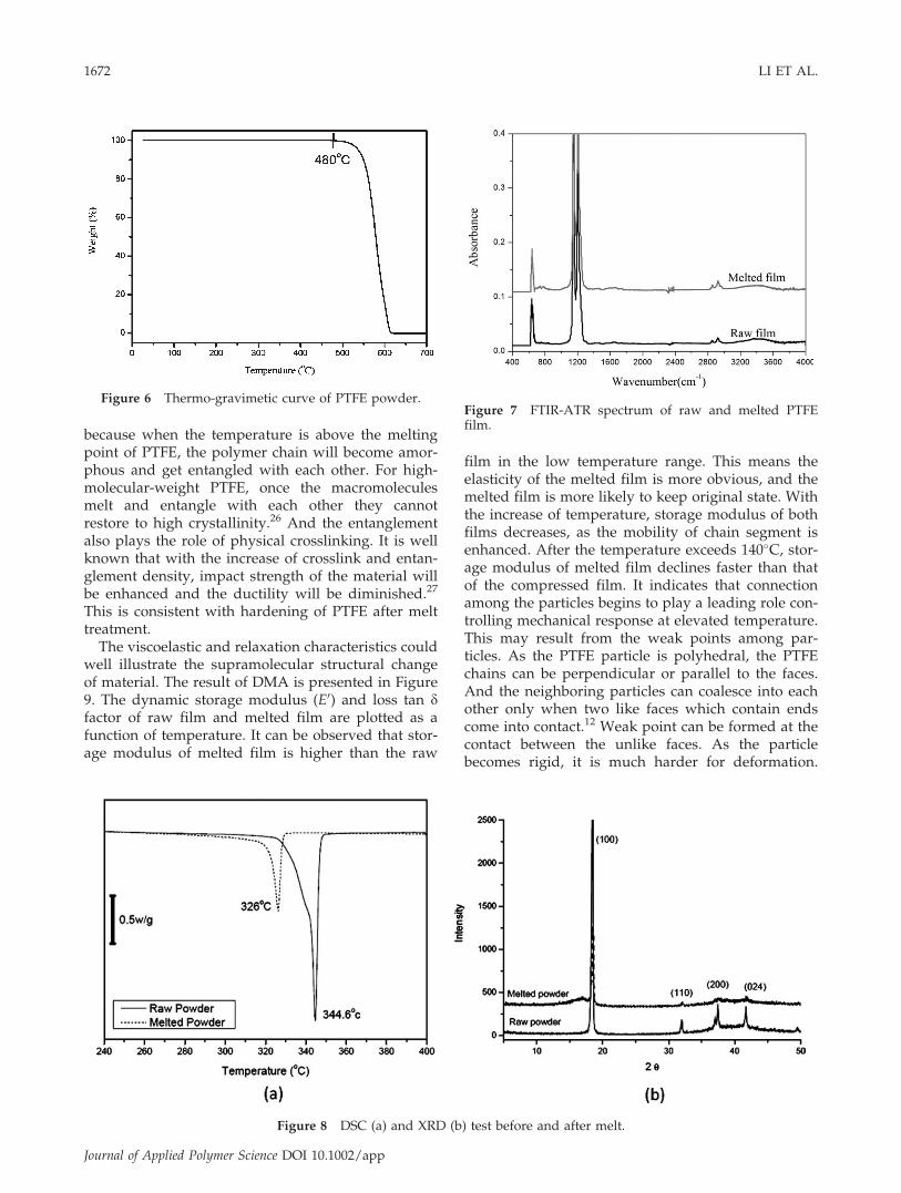
To verify whether the change of material propertywas originated from removal of residual surfactantin polymerization, original PTFE powder was heatedto 380�C in gas chromatography–mass spectrometerto detect the small molecular. But no trace of volatilewas found. In addition, there was no measurabledecrease of weight at the thermo-gravimetic analysisuntil 480�C, which was because of decomposition ofPTFE polymer, shown in Figure 6. The signal of anysmall molecule coated on the PTFE powder was notdetected in solid NMR. FTIR-ATR spectra of com-pressed and melted PTFE film are shown in Figure7. The typical fluorocarbon spectrum associated withstretch vibration CF2 is 1100–1300 cm�1.16,17 No newpeak appears after the film go through high-temper-ature sintering, which means that high-temperaturetreatment does not lead to new chemical bond.Therefore, it can be naturally presumed that the rea-
son for property change is that the melt treatmentalters the PTFE supramolecular structure.It was well documented that supramolecular
structure related closely with material property. Tworequirements for the ultradrawbility include mobilityof chains, and a low degree of entanglement whichis important for the stress transfer. The peculiarPTFE helical structure imposes the chain high mobil-ity, and chains can move through and out of thecrystals easily.18 In the raw PTFE film, the stickynanoparticles are easy to aggregate closely, and theadhesion force among the particles can providesufficient ‘‘entanglement.’’ Because the particle issoft, they would be stretched thinner before they areseparated during drawing. The situation for the filmafter melt treatment is just on the contrary. Thechain movement in rigid particle is relative more dif-ficult, and the stress could not be transferred effec-tively because of the lack of adhesion among thenonsticky particles. As the property change does notresult from removal of surfactant or altered chemicalstructure, it is reasonable to suppose that meltinduces irreversible transformation of PTFE supra-molecular structure.Actually, the unrecoverable crystalline of high-mo-
lecular-weight PTFE after a melting–cooling cyclehas been reported by previous literature.19 The rawPTFE powder which crystallizes from solution dur-ing polymerization tends to form extended chainwith folded ribbons and has perfect crystal.20–23
Thermal analysis and crystalline test, presented inFigure 8, shows that raw PTFE has higher meltingenthalpy and a sharp crystallization peak. After themelting–cooling cycle, the melting point of PTFEbecomes lower; the peak in XRD is not sharp any-more, and a shoulder peak appears around 15�
which is attributed to amorphous region.24,25 This is
Figure 4 Melted PTFE film extended three times at270�C.
Figure 5 Local morphology of breaking end of PTFE film drawn at 270�C: (a) raw film and (b) melted film.
MELT TREATMENT EFFECT—PTFE TENSILE DEFORMATION MECHANISEM 1671
Journal of Applied Polymer Science DOI 10.1002/app
because when the temperature is above the meltingpoint of PTFE, the polymer chain will become amor-phous and get entangled with each other. For high-molecular-weight PTFE, once the macromoleculesmelt and entangle with each other they cannotrestore to high crystallinity.26 And the entanglementalso plays the role of physical crosslinking. It is wellknown that with the increase of crosslink and entan-glement density, impact strength of the material willbe enhanced and the ductility will be diminished.27
This is consistent with hardening of PTFE after melttreatment.
The viscoelastic and relaxation characteristics couldwell illustrate the supramolecular structural changeof material. The result of DMA is presented in Figure9. The dynamic storage modulus (E0) and loss tan dfactor of raw film and melted film are plotted as afunction of temperature. It can be observed that stor-age modulus of melted film is higher than the raw
film in the low temperature range. This means theelasticity of the melted film is more obvious, and themelted film is more likely to keep original state. Withthe increase of temperature, storage modulus of bothfilms decreases, as the mobility of chain segment isenhanced. After the temperature exceeds 140�C, stor-age modulus of melted film declines faster than thatof the compressed film. It indicates that connectionamong the particles begins to play a leading role con-trolling mechanical response at elevated temperature.This may result from the weak points among par-ticles. As the PTFE particle is polyhedral, the PTFEchains can be perpendicular or parallel to the faces.And the neighboring particles can coalesce into eachother only when two like faces which contain endscome into contact.12 Weak point can be formed at thecontact between the unlike faces. As the particlebecomes rigid, it is much harder for deformation.
Figure 6 Thermo-gravimetic curve of PTFE powder.Figure 7 FTIR-ATR spectrum of raw and melted PTFEfilm.
Figure 8 DSC (a) and XRD (b) test before and after melt.
1672 LI ET AL.
Journal of Applied Polymer Science DOI 10.1002/app

When the stress is larger, these weak points will bethe stress concentration point leading to the breakage.After the temperature rises higher than 160�C, thestorage modulus of melted film is smaller than that ofraw PTFE film.
On the curves of loss tan d factor versus tempera-ture, Figure 9(b), a peak can be observed at about150�C for the melted PTFE, which is attributed to bea transition resulted from transition of amorphousPTFE chain.28–30 It is widely agreed by the literaturethat the crystalline PTFE has broad glass transitiontemperature from �100 to �50�C,29,31,32 becauselocal chain mobility is unhindered. The high transi-tion temperature of the amorphous chain can berelated to reduced mobility of macromolecularchains in the entanglement. This also can bereflected by the phenomenon that orientation hap-pens more easily for the crystalline than for theamorphous PTFE chain. It has been documentedthat the crystallites of semicrystalline PTFE obtains a
high degree of alignment under uniaxial elongation,however, the amorphous chains keep an isotropicconformation.33 In other words, the network struc-ture between restricted amorphous PTFE chainslargely suppresses the orientation of the moleculesfrom the molten state.Based on the experiment phenomenon, we pro-
pose the model for submicron structure change ofPTFE during extension as shown in Figure 10. Tosome degree, whether PTFE can be elongated intofiber depends on the competition between the defor-mation capability of particles and boundarystrength. For the raw PTFE film, the stress to deformthe particle is much smaller than the cohesionamong particles, so it can be elongated into long andcontinuous fibrous structure. But for the melted film,the particle boundary weak point breaks before theforce applied on the film increases enough to elon-gate the hard particle into fiber, and some short fiberwould be drawn out.
Figure 9 DMA test of PTFE film before and after melt: (a) storage modulus and (b) tan d.
Figure 10 Model of PTFE film submicron structure change during extension.
MELT TREATMENT EFFECT—PTFE TENSILE DEFORMATION MECHANISEM 1673
Journal of Applied Polymer Science DOI 10.1002/app
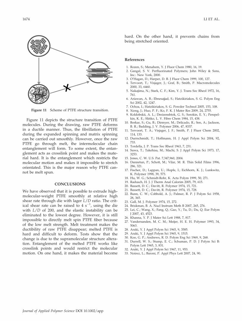
Figure 11 depicts the structure transition of PTFEmolecules. During the drawing, raw PTFE deformsin a ductile manner. Thus, the fibrillation of PTFEduring the expanded spinning and matrix spinningcan be carried out smoothly. However, once the rawPTFE go through melt, the intermolecular chainentanglement will form. To some extent, the entan-glement acts as crosslink point and makes the mate-rial hard. It is the entanglement which restricts themolecular motion and makes it impossible to stretchorientated. This is the major reason why PTFE can-not be melt spun.
CONCLUSIONS
We have observed that it is possible to extrude high-molecular-weight PTFE smoothly at relative highshear rate through die with lager L/D ratio. The crit-ical shear rate can be raised to 4 s�1, using the diewith L/D of 200, and the elastic instability can beeliminated to the lowest degree. However, it is stillimpossible to directly melt spin PTFE fiber becauseof the low melt strength. Melt treatment makes theductibility of raw PTFE disappear; melted PTFE ishard and difficult to deform. Tests show that thechange is due to the supramolecular structure altera-tion. Entanglement of the melted PTFE works likecrosslink points and would restrict the molecularmotion. On one hand, it makes the material become
hard. On the other hand, it prevents chains frombeing stretched oriented.
References
1. Rozen, S.; Menahem, Y. J Fluor Chem 1980, 16, 19.2. Gangal, S. V. Perfluorinated Polymers; John Wiley & Sons,
Inc.: New York, 2000.3. O’Hagan, D.; Harper, D. B. J Fluor Chem 1999, 100, 127.4. Tervoort, T.; Visjager, J.; Graf, B.; Smith, P. Macromolecules
2000, 33, 6460.5. Nakajima, N.; Stark, C. F.; Kim, Y. J. Trans Soc Rheol 1972, 16,
761.6. Ariawan, A. B.; Ebnesajjad, S.; Hatzikiriakos, S. G. Polym Eng
Sci 2002, 42, 1247.7. Ochoa, I.; Hatzikiriakos, S. G. Powder Technol 2005, 153, 108.8. Xiong, J.; Huo, P. F.; Ko, F. K. J Mater Res 2009, 24, 2755.9. Koldobskii, A. L.; Dreizenshtok, G. S.; Sorokin, E. Y.; Perepel-
kin, K. E.; Slinko, L. V. Fibre Chem 1984, 15, 438.10. Borkar, S.; Gu, B.; Dirmyer, M.; Delicado, R.; Sen, A.; Jackson,
B. R.; Badding, J. V. Polymer 2006, 47, 8337.11. Tervoort, T. A.; Visjager, J. F.; Smith, P. J Fluor Chem 2002,
114, 133.12. Durrschmidt, T.; Hoffmann, H. J Appl Polym Sci 2004, 92,
733.13. Tordella, J. P. Trans Soc Rheol 1963, 7, 231.14. Suwa, T.; Takehisa, M.; Machi, S. J Appl Polym Sci 1973, 17,
3253.15. Jones, C. W. U.S. Pat. 7,347,960, 2004.16. Dannetun, P.; Schott, M.; Vilar, M. R. Thin Solid Films 1996,
286, 321.17. Fischer, D.; Lappan, U.; Hopfe, I.; Eichhorn, K. J.; Lunkwitz,
K. Polymer 1998, 39, 573.18. Hu, W. G.; Schmidt-Rohr, K. Acta Polym 1999, 50, 271.19. Radusch, H. J. J Therm Anal Calorim 2005, 79, 615.20. Bassett, D. C.; Davitt, R. Polymer 1974, 15, 721.21. Bassett, D. C.; Davitt, R. Polymer 1974, 15, 728.22. Bunn, C. W.; Cobbold, A. J.; Palmer, R. P. J Polym Sci 1958,
28, 365.23. Gall, M. J. Polymer 1974, 15, 272.24. Briskman, B. A. Nucl Instrum Meth B 2007, 265, 276.25. Lei, C.; Wang, X.; Fang, Q.; Gao, Y.; Tu, D.; Du, Q. Eur Polym
J 2007, 43, 4523.26. Khanna, Y. P. J Mater Sci Lett 1988, 7, 817.27. Vandersanden, M. C. M.; Meijer, H. E. H. Polymer 1993, 34,
5063.28. Araki, Y. J Appl Polym Sci 1965, 9, 3585.29. Araki, Y. J Appl Polym Sci 1965, 9, 1515.30. Koo, G. P.; Andrews, R. D. Polym Eng Sci 1969, 9, 268.31. Durrell, W. S.; Stump, E. C.; Schuman, P. D. J Polym Sci B:
Polym Lett 1965, 3, 831.32. Araki, Y. J Appl Polym Sci 1967, 11, 953.33. Noirez, L.; Baroni, P. Appl Phys Lett 2007, 24, 90.
Figure 11 Scheme of PTFE structure transition.
1674 LI ET AL.
Journal of Applied Polymer Science DOI 10.1002/app