MELSEC iQ-R Simple Motion Module User's Manual (Advanced ...³_logikai_vezérlők_(PLC... ·...
194
MELSEC iQ-R Simple Motion Module User's Manual (Advanced Synchronous Control) -RD77MS2 -RD77GF4 -RD77MS4 -RD77GF8 -RD77MS8 -RD77GF16 -RD77MS16 -RD77GF32
Transcript of MELSEC iQ-R Simple Motion Module User's Manual (Advanced ...³_logikai_vezérlők_(PLC... ·...

MELSEC iQ-R Simple Motion ModuleUser's Manual (Advanced Synchronous Control)
-RD77MS2 -RD77GF4-RD77MS4 -RD77GF8-RD77MS8 -RD77GF16-RD77MS16 -RD77GF32

SAFETY PRECAUTIONS(Read these precautions before using this product.)
Before using this product, please read this manual and the relevant manuals carefully and pay full attention to safety to handle
the product correctly.
The precautions given in this manual are concerned with this product only. Refer to the MELSEC iQ-R Module Configuration
Manual for a description of the PLC system safety precautions.
In this manual, the safety precautions are classified into two levels: " WARNING" and " CAUTION".
Under some circumstances, failure to observe the precautions given under " CAUTION" may lead to serious
consequences.
Observe the precautions of both levels because they are important for personal and system safety.
Make sure that the end users read this manual and then keep the manual in a safe place for future reference.
[Design Precautions]
WARNING● Configure safety circuits external to the programmable controller to ensure that the entire system
operates safely even when a fault occurs in the external power supply or the programmable controller.
Failure to do so may result in an accident due to an incorrect output or malfunction.
(1) Emergency stop circuits, protection circuits, and protective interlock circuits for conflicting
operations (such as forward/reverse rotations or upper/lower limit positioning) must be configured
external to the programmable controller.
(2) When the programmable controller detects an abnormal condition, it stops the operation and all
outputs are:
• Turned off if the overcurrent or overvoltage protection of the power supply module is activated.
• Held or turned off according to the parameter setting if the self-diagnostic function of the CPU
module detects an error such as a watchdog timer error.
(3) All outputs may be turned on if an error occurs in a part, such as an I/O control part, where the
CPU module cannot detect any error. To ensure safety operation in such a case, provide a safety
mechanism or a fail-safe circuit external to the programmable controller. For a fail-safe circuit
example, refer to "General Safety Requirements" in the MELSEC iQ-R Module Configuration
Manual.
(4) Outputs may remain on or off due to a failure of a component such as a relay and transistor in an
output circuit. Configure an external circuit for monitoring output signals that could cause a
serious accident.
● In an output circuit, when a load current exceeding the rated current or an overcurrent caused by a
load short-circuit flows for a long time, it may cause smoke and fire. To prevent this, configure an
external safety circuit, such as a fuse.
● Configure a circuit so that the programmable controller is turned on first and then the external power
supply. If the external power supply is turned on first, an accident may occur due to an incorrect output
or malfunction.
● For the operating status of each station after a communication failure, refer to manuals relevant to the
network. Incorrect output or malfunction due to a communication failure may result in an accident.
WARNING Indicates that incorrect handling may cause hazardous conditions, resulting in death or severe injury.
CAUTION Indicates that incorrect handling may cause hazardous conditions, resulting in minor or moderate injury or property damage.
1

2
[Design Precautions]
WARNING● When connecting an external device with a CPU module or intelligent function module to modify data
of a running programmable controller, configure an interlock circuit in the program to ensure that the
entire system will always operate safely. For other forms of control (such as program modification,
parameter change, forced output, or operating status change) of a running programmable controller,
read the relevant manuals carefully and ensure that the operation is safe before proceeding. Improper
operation may damage machines or cause accidents.
● Especially, when a remote programmable controller is controlled by an external device, immediate
action cannot be taken if a problem occurs in the programmable controller due to a communication
failure. To prevent this, configure an interlock circuit in the program, and determine corrective actions
to be taken between the external device and CPU module in case of a communication failure.
● Do not write any data to the "system area" and "write-protect area" of the buffer memory in the
module. Also, do not use any "use prohibited" signals as an output signal from the CPU module to
each module. Doing so may cause malfunction of the programmable controller system. For the
"system area", "write-protect area", and the "use prohibited" signals, refer to the user's manual for the
module used.
● If a communication cable is disconnected, the network may be unstable, resulting in a communication
failure of multiple stations. Configure an interlock circuit in the program to ensure that the entire
system will always operate safely even if communications fail. Failure to do so may result in an
accident due to an incorrect output or malfunction.
● To maintain the safety of the programmable controller system against unauthorized access from
external devices via the network, take appropriate measures. To maintain the safety against
unauthorized access via the Internet, take measures such as installing a firewall.
● Configure safety circuits external to the programmable controller to ensure that the entire system
operates safely even when a fault occurs in the external power supply or the programmable controller.
Failure to do so may result in an accident due to an incorrect output or malfunction.
(1) Machine home position return is controlled by two kinds of data: a home position return direction
and a home position return speed. Deceleration starts when the proximity dog signal turns on. If
an incorrect home position return direction is set, motion control may continue without
deceleration. To prevent machine damage caused by this, configure an interlock circuit external to
the programmable controller.
(2) When the module detects an error, the motion slows down and stops or the motion rapidly stops,
depending on the stop group setting in parameter. Set the parameter to meet the specifications of
a positioning control system. In addition, set the home position return parameter and positioning
data within the specified setting range.
(3) Outputs may remain on or off, or become undefined due to a failure of a component such as an
insulation element and transistor in an output circuit, where the module cannot detect any error. In
a system that the incorrect output could cause a serious accident, configure an external circuit for
monitoring output signals.
● If safety standards (ex., robot safety rules, etc.,) apply to the system using the module, servo amplifier
and servomotor, make sure that the safety standards are satisfied.
● Construct a safety circuit externally of the module or servo amplifier if the abnormal operation of the
module or servo amplifier differs from the safety directive operation in the system.

[Design Precautions]
[Design Precautions]
[Installation Precautions]
WARNING● Do not remove the SSCNET cable while turning on the control circuit power supply of the module
and servo amplifier. Do not see directly the light generated from SSCNET connector of the module
or servo amplifier and the end of SSCNET cable. When the light gets into eyes, you may feel
something wrong with eyes. (The light source of SSCNET complies with class1 defined in JISC6802
or IEC60825-1.)
CAUTION● Do not install the control lines or communication cables together with the main circuit lines or power
cables. Keep a distance of 100 mm or more between them. Failure to do so may result in malfunction
due to noise.
● During control of an inductive load such as a lamp, heater, or solenoid valve, a large current
(approximately ten times greater than normal) may flow when the output is turned from off to on.
Therefore, use a module that has a sufficient current rating.
● After the CPU module is powered on or is reset, the time taken to enter the RUN status varies
depending on the system configuration, parameter settings, and/or program size. Design circuits so
that the entire system will always operate safely, regardless of the time.
● Do not power off the programmable controller or reset the CPU module while the settings are being
written. Doing so will make the data in the flash ROM and SD memory card undefined. The values
need to be set in the buffer memory and written to the flash ROM and SD memory card again. Doing
so also may cause malfunction or failure of the module.
● When changing the operating status of the CPU module from external devices (such as the remote
RUN/STOP functions), select "Do Not Open in Program" for "Opening Method Setting" in the module
parameters. If "Open in Program" is selected, an execution of the remote STOP function causes the
communication line to close. Consequently, the CPU module cannot reopen the line, and external
devices cannot execute the remote RUN function.
WARNING● Shut off the external power supply (all phases) used in the system before mounting or removing the
module. Failure to do so may result in electric shock or cause the module to fail or malfunction.
3

4
[Installation Precautions]
[Wiring Precautions]
CAUTION● Use the programmable controller in an environment that meets the general specifications in the Safety
Guidelines included with the base unit. Failure to do so may result in electric shock, fire, malfunction,
or damage to or deterioration of the product.
● To mount a module, place the concave part(s) located at the bottom onto the guide(s) of the base unit,
and push in the module until the hook(s) located at the top snaps into place. Incorrect interconnection
may cause malfunction, failure, or drop of the module.
● To mount a module with no module fixing hook, place the concave part(s) located at the bottom onto
the guide(s) of the base unit, push in the module, and fix it with screw(s). Incorrect interconnection
may cause malfunction, failure, or drop of the module.
● When using the programmable controller in an environment of frequent vibrations, fix the module with
a screw.
● Tighten the screws within the specified torque range. Undertightening can cause drop of the screw,
short circuit, or malfunction. Overtightening can damage the screw and/or module, resulting in drop,
short circuit, or malfunction.
● When using an extension cable, connect it to the extension cable connector of the base unit securely.
Check the connection for looseness. Poor contact may cause malfunction.
● When using an SD memory card, fully insert it into the SD memory card slot. Check that it is inserted
completely. Poor contact may cause malfunction.
● Securely insert an extended SRAM cassette into the cassette connector of the CPU module. After
insertion, close the cassette cover and check that the cassette is inserted completely. Poor contact
may cause malfunction.
● Do not directly touch any conductive parts and electronic components of the module, SD memory
card, extended SRAM cassette, or connector. Doing so can cause malfunction or failure of the
module.
WARNING● Shut off the external power supply (all phases) used in the system before installation and wiring.
Failure to do so may result in electric shock or cause the module to fail or malfunction.
● After installation and wiring, attach the included terminal cover to the module before turning it on for
operation. Failure to do so may result in electric shock.
[Wiring Precautions]
CAUTION● Individually ground the FG and LG terminals of the programmable controller with a ground resistance
of 100 ohms or less. Failure to do so may result in electric shock or malfunction.
● Use applicable solderless terminals and tighten them within the specified torque range. If any spade
solderless terminal is used, it may be disconnected when the terminal screw comes loose, resulting in
failure.
● Check the rated voltage and signal layout before wiring to the module, and connect the cables
correctly. Connecting a power supply with a different voltage rating or incorrect wiring may cause fire
or failure.
● Connectors for external devices must be crimped or pressed with the tool specified by the
manufacturer, or must be correctly soldered. Incomplete connections may cause short circuit, fire, or
malfunction.
● Securely connect the connector to the module. Poor contact may cause malfunction.
● Do not install the control lines or communication cables together with the main circuit lines or power
cables. Keep a distance of 100 mm or more between them. Failure to do so may result in malfunction
due to noise.
● Place the cables in a duct or clamp them. If not, dangling cable may swing or inadvertently be pulled,
resulting in damage to the module or cables or malfunction due to poor contact. Do not clamp the
extension cables with the jacket stripped.
● Check the interface type and correctly connect the cable. Incorrect wiring (connecting the cable to an
incorrect interface) may cause failure of the module and external device.
● Tighten the terminal screws or connector screws within the specified torque range. Undertightening
can cause drop of the screw, short circuit, fire, or malfunction. Overtightening can damage the screw
and/or module, resulting in drop, short circuit, fire, or malfunction.
● When disconnecting the cable from the module, do not pull the cable by the cable part. For the cable
with connector, hold the connector part of the cable. For the cable connected to the terminal block,
loosen the terminal screw. Pulling the cable connected to the module may result in malfunction or
damage to the module or cable.
● Prevent foreign matter such as dust or wire chips from entering the module. Such foreign matter can
cause a fire, failure, or malfunction.
● A protective film is attached to the top of the module to prevent foreign matter, such as wire chips,
from entering the module during wiring. Do not remove the film during wiring. Remove it for heat
dissipation before system operation.
● Programmable controllers must be installed in control panels. Connect the main power supply to the
power supply module in the control panel through a relay terminal block. Wiring and replacement of a
power supply module must be performed by qualified maintenance personnel with knowledge of
protection against electric shock. For wiring, refer to the MELSEC iQ-R Module Configuration Manual.
● For Ethernet cables to be used in the system, select the ones that meet the specifications in the user's
manual for the module used. If not, normal data transmission is not guaranteed.
5

6
[Startup and Maintenance Precautions]
[Startup and Maintenance Precautions]
WARNING● Do not touch any terminal while power is on. Doing so will cause electric shock or malfunction.
● Correctly connect the battery connector. Do not charge, disassemble, heat, short-circuit, solder, or
throw the battery into the fire. Also, do not expose it to liquid or strong shock. Doing so will cause the
battery to produce heat, explode, ignite, or leak, resulting in injury and fire.
● Shut off the external power supply (all phases) used in the system before cleaning the module or
retightening the terminal screws, connector screws, or module fixing screws. Failure to do so may
result in electric shock.
CAUTION● When connecting an external device with a CPU module or intelligent function module to modify data
of a running programmable controller, configure an interlock circuit in the program to ensure that the
entire system will always operate safely. For other forms of control (such as program modification,
parameter change, forced output, or operating status change) of a running programmable controller,
read the relevant manuals carefully and ensure that the operation is safe before proceeding. Improper
operation may damage machines or cause accidents.
● Especially, when a remote programmable controller is controlled by an external device, immediate
action cannot be taken if a problem occurs in the programmable controller due to a communication
failure. To prevent this, configure an interlock circuit in the program, and determine corrective actions
to be taken between the external device and CPU module in case of a communication failure.
● Do not disassemble or modify the modules. Doing so may cause failure, malfunction, injury, or a fire.
● Use any radio communication device such as a cellular phone or PHS (Personal Handy-phone
System) more than 25 cm away in all directions from the programmable controller. Failure to do so
may cause malfunction.
● Shut off the external power supply (all phases) used in the system before mounting or removing the
module. Failure to do so may cause the module to fail or malfunction.
● Tighten the screws within the specified torque range. Undertightening can cause drop of the
component or wire, short circuit, or malfunction. Overtightening can damage the screw and/or module,
resulting in drop, short circuit, or malfunction.
● After the first use of the product, do not mount/remove the module to/from the base unit, and the
terminal block to/from the module, and do not insert/remove the extended SRAM cassette to/from the
CPU module more than 50 times (IEC 61131-2 compliant) respectively. Exceeding the limit may cause
malfunction.
● After the first use of the product, do not insert/remove the SD memory card to/from the CPU module
more than 500 times. Exceeding the limit may cause malfunction.
● Do not touch the metal terminals on the back side of the SD memory card. Doing so may cause
malfunction or failure of the module.
● Do not touch the integrated circuits on the circuit board of an extended SRAM cassette. Doing so may
cause malfunction or failure of the module.
● Do not drop or apply shock to the battery to be installed in the module. Doing so may damage the
battery, causing the battery fluid to leak inside the battery. If the battery is dropped or any shock is
applied to it, dispose of it without using.
[Startup and Maintenance Precautions]
[Operating Precautions]
[Disposal Precautions]
CAUTION● Startup and maintenance of a control panel must be performed by qualified maintenance personnel
with knowledge of protection against electric shock. Lock the control panel so that only qualified
maintenance personnel can operate it.
● Before handling the module, touch a conducting object such as a grounded metal to discharge the
static electricity from the human body. Failure to do so may cause the module to fail or malfunction.
● Before testing the operation, set a low speed value for the speed limit parameter so that the operation
can be stopped immediately upon occurrence of a hazardous condition.
● Confirm and adjust the program and each parameter before operation. Unpredictable movements
may occur depending on the machine.
● When using the absolute position system function, on starting up, and when the module or absolute
position motor has been replaced, always perform a home position return.
● Before starting the operation, confirm the brake function.
● Do not perform a megger test (insulation resistance measurement) during inspection.
● After maintenance and inspections are completed, confirm that the position detection of the absolute
position detection function is correct.
● Lock the control panel and prevent access to those who are not certified to handle or install electric
equipment.
CAUTION● When changing data and operating status, and modifying program of the running programmable
controller from an external device such as a personal computer connected to an intelligent function
module, read relevant manuals carefully and ensure the safety before operation. Incorrect change or
modification may cause system malfunction, damage to the machines, or accidents.
● Do not power off the programmable controller or reset the CPU module while the setting values in the
buffer memory are being written to the flash ROM in the module. Doing so will make the data in the
flash ROM and SD memory card undefined. The values need to be set in the buffer memory and
written to the flash ROM and SD memory card again. Doing so also may cause malfunction or failure
of the module.
● Note that when the reference axis speed is specified for interpolation operation, the speed of the
partner axis (2nd, 3rd, or 4th axis) may exceed the speed limit value.
● Do not go near the machine during test operations or during operations such as teaching. Doing so
may lead to injuries.
CAUTION● When disposing of this product, treat it as industrial waste.
● When disposing of batteries, separate them from other wastes according to the local regulations. For
details on battery regulations in EU member states, refer to the MELSEC iQ-R Module Configuration
Manual.
7
8
[Transportation Precautions]
CAUTION● When transporting lithium batteries, follow the transportation regulations. For details on the regulated
models, refer to the MELSEC iQ-R Module Configuration Manual.
● The halogens (such as fluorine, chlorine, bromine, and iodine), which are contained in a fumigant
used for disinfection and pest control of wood packaging materials, may cause failure of the product.
Prevent the entry of fumigant residues into the product or consider other methods (such as heat
treatment) instead of fumigation. The disinfection and pest control measures must be applied to
unprocessed raw wood.

CONDITIONS OF USE FOR THE PRODUCT(1) Mitsubishi programmable controller ("the PRODUCT") shall be used in conditions;
i) where any problem, fault or failure occurring in the PRODUCT, if any, shall not lead to any major or serious accident; and ii) where the backup and fail-safe function are systematically or automatically provided outside of the PRODUCT for the case of any problem, fault or failure occurring in the PRODUCT.
(2) The PRODUCT has been designed and manufactured for the purpose of being used in general industries.MITSUBISHI SHALL HAVE NO RESPONSIBILITY OR LIABILITY (INCLUDING, BUT NOT LIMITED TO ANY AND ALL RESPONSIBILITY OR LIABILITY BASED ON CONTRACT, WARRANTY, TORT, PRODUCT LIABILITY) FOR ANY INJURY OR DEATH TO PERSONS OR LOSS OR DAMAGE TO PROPERTY CAUSED BY the PRODUCT THAT ARE OPERATED OR USED IN APPLICATION NOT INTENDED OR EXCLUDED BY INSTRUCTIONS, PRECAUTIONS, OR WARNING CONTAINED IN MITSUBISHI'S USER, INSTRUCTION AND/OR SAFETY MANUALS, TECHNICAL BULLETINS AND GUIDELINES FOR the PRODUCT. ("Prohibited Application")Prohibited Applications include, but not limited to, the use of the PRODUCT in;• Nuclear Power Plants and any other power plants operated by Power companies, and/or any other cases in which the
public could be affected if any problem or fault occurs in the PRODUCT.• Railway companies or Public service purposes, and/or any other cases in which establishment of a special quality
assurance system is required by the Purchaser or End User.• Aircraft or Aerospace, Medical applications, Train equipment, transport equipment such as Elevator and Escalator,
Incineration and Fuel devices, Vehicles, Manned transportation, Equipment for Recreation and Amusement, and Safety devices, handling of Nuclear or Hazardous Materials or Chemicals, Mining and Drilling, and/or other applications where there is a significant risk of injury to the public or property.
Notwithstanding the above, restrictions Mitsubishi may in its sole discretion, authorize use of the PRODUCT in one or more of the Prohibited Applications, provided that the usage of the PRODUCT is limited only for the specific applications agreed to by Mitsubishi and provided further that no special quality assurance or fail-safe, redundant or other safety features which exceed the general specifications of the PRODUCTs are required. For details, please contact the Mitsubishi representative in your region.
9
10
INTRODUCTIONThank you for purchasing the Mitsubishi MELSEC iQ-R series programmable controllers.
This manual describes the functions and programming of the relevant products listed below. Before using this product, please
read this manual and the relevant manuals carefully and develop familiarity with the functions and performance of the
MELSEC iQ-R series programmable controller to handle the product correctly.
When applying the program examples provided in this manual to an actual system, ensure the applicability and confirm that it
will not cause system control problems.
Please make sure that the end users read this manual.
Relevant productsRD77MS2, RD77MS4, RD77MS8, RD77MS16
RD77GF4, RD77GF8, RD77GF16, RD77GF32
Symbols used in this manual are shown below.
A serial No. is inserted in the "**" mark.
• [Pr.**]: Symbols indicating positioning parameter or home position return parameter items
• [Da.**]: Symbols indicating positioning data or block start data items
• [Md.**]: Symbols indicating monitor data items
• [Cd.**]: Symbols indicating control data items
• [RD77MS]: Symbols indicating that it corresponds to only RD77MS
• [RD77GF]: Symbols indicating that it corresponds to only RD77GF
COMPLIANCE WITH EMC AND LOW VOLTAGE DIRECTIVES
Method of ensuring complianceTo ensure that Mitsubishi programmable controllers maintain EMC and Low Voltage Directives when incorporated into other
machinery or equipment, certain measures may be necessary. Please refer to one of the following manuals.
MELSEC iQ-R Module Configuration Manual
Safety Guidelines (This manual is included with the base unit.)
The CE mark on the side of the programmable controller indicates compliance with EMC and Low Voltage Directives.
Additional measuresTo ensure that this product maintains EMC and Low Voltage Directives, please refer to one of the following manuals.
MELSEC iQ-R Module Configuration Manual
Safety Guidelines (This manual is included with the base unit.)
CO
NT
EN
TS
CONTENTSSAFETY PRECAUTIONS . . . . . . . . . . . . . . . . . . . . . . . . . . . . . . . . . . . . . . . . . . . . . . . . . . . . . . . . . . . . . . . . . . . .1
CONDITIONS OF USE FOR THE PRODUCT . . . . . . . . . . . . . . . . . . . . . . . . . . . . . . . . . . . . . . . . . . . . . . . . . . . .9
INTRODUCTION. . . . . . . . . . . . . . . . . . . . . . . . . . . . . . . . . . . . . . . . . . . . . . . . . . . . . . . . . . . . . . . . . . . . . . . . . .10
COMPLIANCE WITH EMC AND LOW VOLTAGE DIRECTIVES . . . . . . . . . . . . . . . . . . . . . . . . . . . . . . . . . . . . .10
RELEVANT MANUALS . . . . . . . . . . . . . . . . . . . . . . . . . . . . . . . . . . . . . . . . . . . . . . . . . . . . . . . . . . . . . . . . . . . . .13
TERMS . . . . . . . . . . . . . . . . . . . . . . . . . . . . . . . . . . . . . . . . . . . . . . . . . . . . . . . . . . . . . . . . . . . . . . . . . . . . . . . . .14
CHAPTER 1 OUTLINE OF ADVANCED SYNCHRONOUS CONTROL 15
1.1 Outline of Synchronous Control . . . . . . . . . . . . . . . . . . . . . . . . . . . . . . . . . . . . . . . . . . . . . . . . . . . . . . . . . . . 15
1.2 Performance Specifications . . . . . . . . . . . . . . . . . . . . . . . . . . . . . . . . . . . . . . . . . . . . . . . . . . . . . . . . . . . . . . . 19
1.3 Operation Method of Synchronous Control . . . . . . . . . . . . . . . . . . . . . . . . . . . . . . . . . . . . . . . . . . . . . . . . . . 22
Synchronous control execution procedure . . . . . . . . . . . . . . . . . . . . . . . . . . . . . . . . . . . . . . . . . . . . . . . . . . . . . 22
Starting/ending for synchronous control . . . . . . . . . . . . . . . . . . . . . . . . . . . . . . . . . . . . . . . . . . . . . . . . . . . . . . . 23
Stop operation of output axis . . . . . . . . . . . . . . . . . . . . . . . . . . . . . . . . . . . . . . . . . . . . . . . . . . . . . . . . . . . . . . . . 26
CHAPTER 2 INPUT AXIS MODULE 28
2.1 Servo Input Axis . . . . . . . . . . . . . . . . . . . . . . . . . . . . . . . . . . . . . . . . . . . . . . . . . . . . . . . . . . . . . . . . . . . . . . . . 28
Overview of servo input axis . . . . . . . . . . . . . . . . . . . . . . . . . . . . . . . . . . . . . . . . . . . . . . . . . . . . . . . . . . . . . . . . 28
Servo input axis parameters . . . . . . . . . . . . . . . . . . . . . . . . . . . . . . . . . . . . . . . . . . . . . . . . . . . . . . . . . . . . . . . . 30
Servo input axis monitor data . . . . . . . . . . . . . . . . . . . . . . . . . . . . . . . . . . . . . . . . . . . . . . . . . . . . . . . . . . . . . . . 33
2.2 Synchronous Encoder Axis . . . . . . . . . . . . . . . . . . . . . . . . . . . . . . . . . . . . . . . . . . . . . . . . . . . . . . . . . . . . . . . 35
Overview of synchronous encoder axis. . . . . . . . . . . . . . . . . . . . . . . . . . . . . . . . . . . . . . . . . . . . . . . . . . . . . . . . 35
Setting method for synchronous encoder . . . . . . . . . . . . . . . . . . . . . . . . . . . . . . . . . . . . . . . . . . . . . . . . . . . . . . 38
Synchronous encoder axis parameters . . . . . . . . . . . . . . . . . . . . . . . . . . . . . . . . . . . . . . . . . . . . . . . . . . . . . . . . 46
Synchronous encoder axis parameters via link device [RD77GF] . . . . . . . . . . . . . . . . . . . . . . . . . . . . . . . . . . . 52
Synchronous encoder axis control data . . . . . . . . . . . . . . . . . . . . . . . . . . . . . . . . . . . . . . . . . . . . . . . . . . . . . . . 55
Synchronous encoder axis monitor data . . . . . . . . . . . . . . . . . . . . . . . . . . . . . . . . . . . . . . . . . . . . . . . . . . . . . . . 59
CHAPTER 3 CAM FUNCTION 62
3.1 Control Details for Cam Function . . . . . . . . . . . . . . . . . . . . . . . . . . . . . . . . . . . . . . . . . . . . . . . . . . . . . . . . . . 62
3.2 Create Cam Data . . . . . . . . . . . . . . . . . . . . . . . . . . . . . . . . . . . . . . . . . . . . . . . . . . . . . . . . . . . . . . . . . . . . . . . . 69
Memory configuration of cam data . . . . . . . . . . . . . . . . . . . . . . . . . . . . . . . . . . . . . . . . . . . . . . . . . . . . . . . . . . . 69
Cam data operation function . . . . . . . . . . . . . . . . . . . . . . . . . . . . . . . . . . . . . . . . . . . . . . . . . . . . . . . . . . . . . . . . 74
Cam auto-generation function . . . . . . . . . . . . . . . . . . . . . . . . . . . . . . . . . . . . . . . . . . . . . . . . . . . . . . . . . . . . . . . 79
CHAPTER 4 ADVANCED SYNCHRONOUS CONTROL 91
4.1 Main Shaft Module. . . . . . . . . . . . . . . . . . . . . . . . . . . . . . . . . . . . . . . . . . . . . . . . . . . . . . . . . . . . . . . . . . . . . . . 91
Overview of main shaft module . . . . . . . . . . . . . . . . . . . . . . . . . . . . . . . . . . . . . . . . . . . . . . . . . . . . . . . . . . . . . . 91
Main shaft parameters. . . . . . . . . . . . . . . . . . . . . . . . . . . . . . . . . . . . . . . . . . . . . . . . . . . . . . . . . . . . . . . . . . . . . 92
Main shaft clutch parameters . . . . . . . . . . . . . . . . . . . . . . . . . . . . . . . . . . . . . . . . . . . . . . . . . . . . . . . . . . . . . . . 94
Main shaft clutch control data . . . . . . . . . . . . . . . . . . . . . . . . . . . . . . . . . . . . . . . . . . . . . . . . . . . . . . . . . . . . . . 100
4.2 Auxiliary Shaft Module . . . . . . . . . . . . . . . . . . . . . . . . . . . . . . . . . . . . . . . . . . . . . . . . . . . . . . . . . . . . . . . . . . 101
Overview of auxiliary shaft module . . . . . . . . . . . . . . . . . . . . . . . . . . . . . . . . . . . . . . . . . . . . . . . . . . . . . . . . . . 101
Auxiliary shaft parameters . . . . . . . . . . . . . . . . . . . . . . . . . . . . . . . . . . . . . . . . . . . . . . . . . . . . . . . . . . . . . . . . . 101
Auxiliary shaft clutch parameters. . . . . . . . . . . . . . . . . . . . . . . . . . . . . . . . . . . . . . . . . . . . . . . . . . . . . . . . . . . . 103
Auxiliary shaft clutch control data . . . . . . . . . . . . . . . . . . . . . . . . . . . . . . . . . . . . . . . . . . . . . . . . . . . . . . . . . . . 109
4.3 Clutch . . . . . . . . . . . . . . . . . . . . . . . . . . . . . . . . . . . . . . . . . . . . . . . . . . . . . . . . . . . . . . . . . . . . . . . . . . . . . . . . 110
Overview of clutch . . . . . . . . . . . . . . . . . . . . . . . . . . . . . . . . . . . . . . . . . . . . . . . . . . . . . . . . . . . . . . . . . . . . . . . 110
11
12
Control method for clutch . . . . . . . . . . . . . . . . . . . . . . . . . . . . . . . . . . . . . . . . . . . . . . . . . . . . . . . . . . . . . . . . . 110
Smoothing method for clutch. . . . . . . . . . . . . . . . . . . . . . . . . . . . . . . . . . . . . . . . . . . . . . . . . . . . . . . . . . . . . . . 117
Use example of clutch . . . . . . . . . . . . . . . . . . . . . . . . . . . . . . . . . . . . . . . . . . . . . . . . . . . . . . . . . . . . . . . . . . . . 122
4.4 Speed Change Gear Module. . . . . . . . . . . . . . . . . . . . . . . . . . . . . . . . . . . . . . . . . . . . . . . . . . . . . . . . . . . . . . 123
Overview of speed change gear module . . . . . . . . . . . . . . . . . . . . . . . . . . . . . . . . . . . . . . . . . . . . . . . . . . . . . . 123
Speed change gear parameters . . . . . . . . . . . . . . . . . . . . . . . . . . . . . . . . . . . . . . . . . . . . . . . . . . . . . . . . . . . . 124
4.5 Output Axis Module. . . . . . . . . . . . . . . . . . . . . . . . . . . . . . . . . . . . . . . . . . . . . . . . . . . . . . . . . . . . . . . . . . . . . 125
Overview of output axis module . . . . . . . . . . . . . . . . . . . . . . . . . . . . . . . . . . . . . . . . . . . . . . . . . . . . . . . . . . . . 125
Output axis parameters . . . . . . . . . . . . . . . . . . . . . . . . . . . . . . . . . . . . . . . . . . . . . . . . . . . . . . . . . . . . . . . . . . . 127
4.6 Synchronous Control Change Function . . . . . . . . . . . . . . . . . . . . . . . . . . . . . . . . . . . . . . . . . . . . . . . . . . . . 131
Overview of synchronous control change function . . . . . . . . . . . . . . . . . . . . . . . . . . . . . . . . . . . . . . . . . . . . . . 131
Synchronous control change control data . . . . . . . . . . . . . . . . . . . . . . . . . . . . . . . . . . . . . . . . . . . . . . . . . . . . . 131
4.7 Synchronous Control Monitor Data. . . . . . . . . . . . . . . . . . . . . . . . . . . . . . . . . . . . . . . . . . . . . . . . . . . . . . . . 135
4.8 Phase Compensation Function . . . . . . . . . . . . . . . . . . . . . . . . . . . . . . . . . . . . . . . . . . . . . . . . . . . . . . . . . . . 140
4.9 Output Axis Sub Functions . . . . . . . . . . . . . . . . . . . . . . . . . . . . . . . . . . . . . . . . . . . . . . . . . . . . . . . . . . . . . . 142
CHAPTER 5 ADVANCED SYNCHRONOUS CONTROL INITIAL POSITION 143
5.1 Synchronous Control Initial Position . . . . . . . . . . . . . . . . . . . . . . . . . . . . . . . . . . . . . . . . . . . . . . . . . . . . . . 143
5.2 Synchronous Control Initial Position Parameters . . . . . . . . . . . . . . . . . . . . . . . . . . . . . . . . . . . . . . . . . . . . 147
5.3 Cam Axis Position Restoration Method . . . . . . . . . . . . . . . . . . . . . . . . . . . . . . . . . . . . . . . . . . . . . . . . . . . . 150
Cam axis current value per cycle restoration . . . . . . . . . . . . . . . . . . . . . . . . . . . . . . . . . . . . . . . . . . . . . . . . . . 150
Cam reference position restoration . . . . . . . . . . . . . . . . . . . . . . . . . . . . . . . . . . . . . . . . . . . . . . . . . . . . . . . . . . 154
Cam axis feed current value restoration . . . . . . . . . . . . . . . . . . . . . . . . . . . . . . . . . . . . . . . . . . . . . . . . . . . . . . 156
5.4 Synchronous Control Analysis Mode . . . . . . . . . . . . . . . . . . . . . . . . . . . . . . . . . . . . . . . . . . . . . . . . . . . . . . 159
5.5 Cam Position Calculation Function . . . . . . . . . . . . . . . . . . . . . . . . . . . . . . . . . . . . . . . . . . . . . . . . . . . . . . . . 162
Cam position calculation control data . . . . . . . . . . . . . . . . . . . . . . . . . . . . . . . . . . . . . . . . . . . . . . . . . . . . . . . . 162
Cam position calculation monitor data. . . . . . . . . . . . . . . . . . . . . . . . . . . . . . . . . . . . . . . . . . . . . . . . . . . . . . . . 164
5.6 Method to Restart Synchronous Control . . . . . . . . . . . . . . . . . . . . . . . . . . . . . . . . . . . . . . . . . . . . . . . . . . . 169
APPENDICES 170
Appendix 1 List of Buffer Memory Addresses (for Synchronous Control) . . . . . . . . . . . . . . . . . . . . . . . . . . . . . 170
Appendix 2 Sample Program of Synchronous Control of the RD77MS . . . . . . . . . . . . . . . . . . . . . . . . . . . . . . . . 181
INDEX 186
REVISIONS. . . . . . . . . . . . . . . . . . . . . . . . . . . . . . . . . . . . . . . . . . . . . . . . . . . . . . . . . . . . . . . . . . . . . . . . . . . . .188
WARRANTY . . . . . . . . . . . . . . . . . . . . . . . . . . . . . . . . . . . . . . . . . . . . . . . . . . . . . . . . . . . . . . . . . . . . . . . . . . . .189
TRADEMARKS . . . . . . . . . . . . . . . . . . . . . . . . . . . . . . . . . . . . . . . . . . . . . . . . . . . . . . . . . . . . . . . . . . . . . . . . . .190
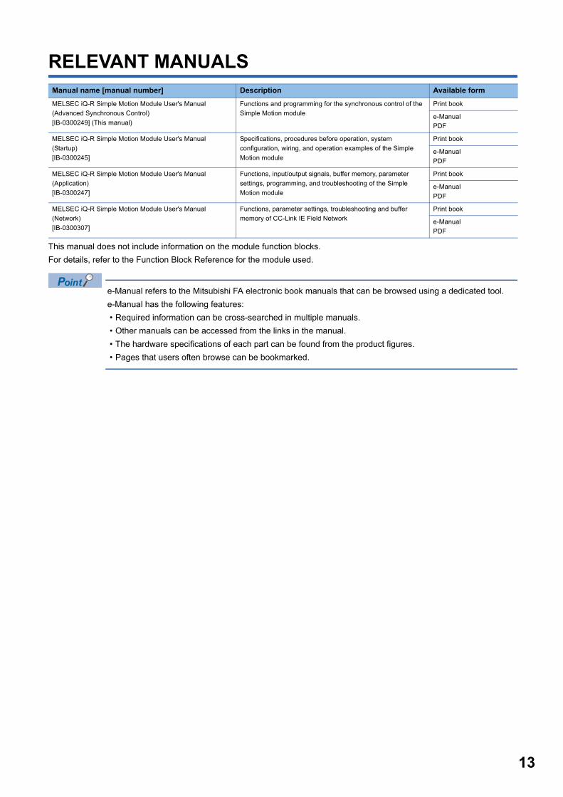
RELEVANT MANUALS
This manual does not include information on the module function blocks.
For details, refer to the Function Block Reference for the module used.
e-Manual refers to the Mitsubishi FA electronic book manuals that can be browsed using a dedicated tool.
e-Manual has the following features:
• Required information can be cross-searched in multiple manuals.
• Other manuals can be accessed from the links in the manual.
• The hardware specifications of each part can be found from the product figures.
• Pages that users often browse can be bookmarked.
Manual name [manual number] Description Available form
MELSEC iQ-R Simple Motion Module User's Manual
(Advanced Synchronous Control)
[IB-0300249] (This manual)
Functions and programming for the synchronous control of the
Simple Motion module
Print book
e-Manual
MELSEC iQ-R Simple Motion Module User's Manual
(Startup)
[IB-0300245]
Specifications, procedures before operation, system
configuration, wiring, and operation examples of the Simple
Motion module
Print book
e-Manual
MELSEC iQ-R Simple Motion Module User's Manual
(Application)
[IB-0300247]
Functions, input/output signals, buffer memory, parameter
settings, programming, and troubleshooting of the Simple
Motion module
Print book
e-Manual
MELSEC iQ-R Simple Motion Module User's Manual
(Network)
[IB-0300307]
Functions, parameter settings, troubleshooting and buffer
memory of CC-Link IE Field Network
Print book
e-Manual
13
14
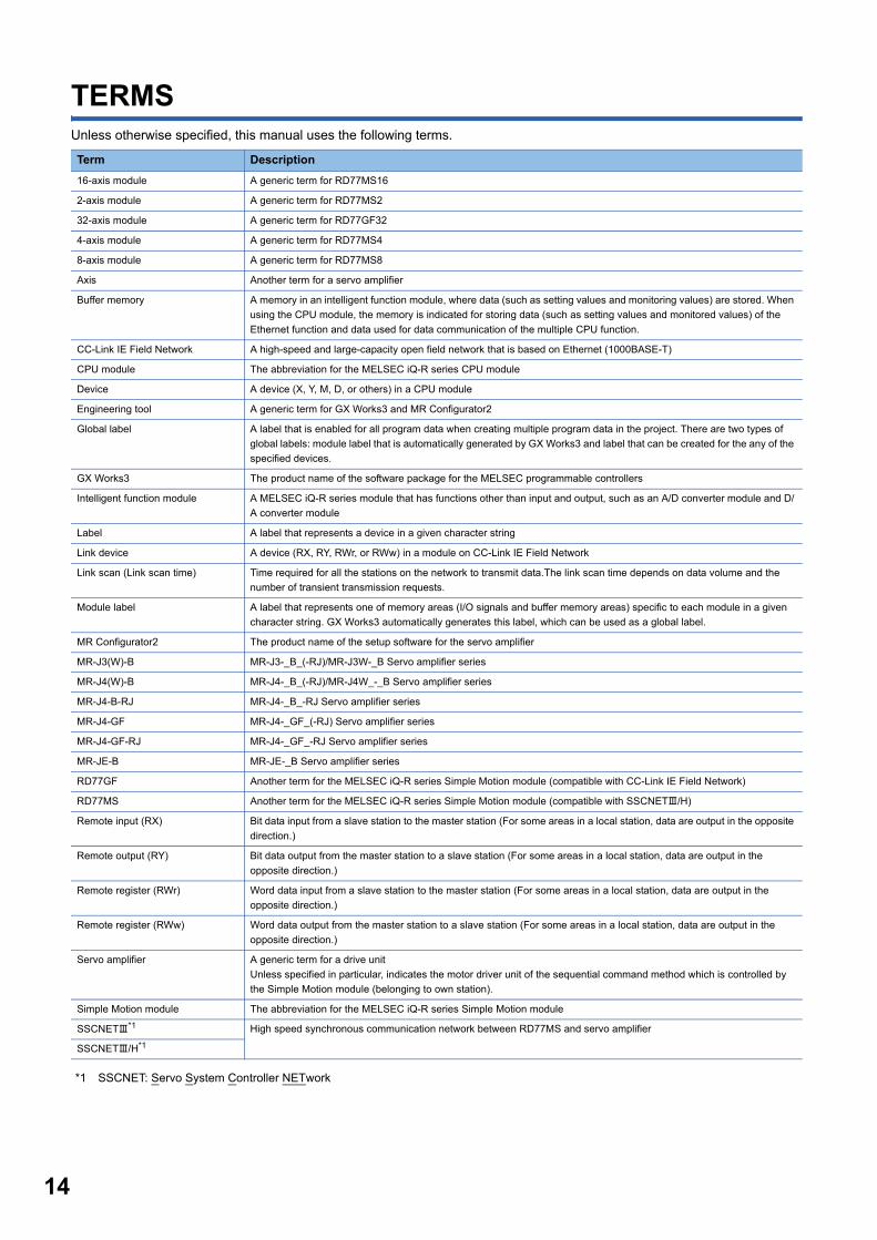
TERMSUnless otherwise specified, this manual uses the following terms.
*1 SSCNET: Servo System Controller NETwork
Term Description
16-axis module A generic term for RD77MS16
2-axis module A generic term for RD77MS2
32-axis module A generic term for RD77GF32
4-axis module A generic term for RD77MS4
8-axis module A generic term for RD77MS8
Axis Another term for a servo amplifier
Buffer memory A memory in an intelligent function module, where data (such as setting values and monitoring values) are stored. When
using the CPU module, the memory is indicated for storing data (such as setting values and monitored values) of the
Ethernet function and data used for data communication of the multiple CPU function.
CC-Link IE Field Network A high-speed and large-capacity open field network that is based on Ethernet (1000BASE-T)
CPU module The abbreviation for the MELSEC iQ-R series CPU module
Device A device (X, Y, M, D, or others) in a CPU module
Engineering tool A generic term for GX Works3 and MR Configurator2
Global label A label that is enabled for all program data when creating multiple program data in the project. There are two types of
global labels: module label that is automatically generated by GX Works3 and label that can be created for the any of the
specified devices.
GX Works3 The product name of the software package for the MELSEC programmable controllers
Intelligent function module A MELSEC iQ-R series module that has functions other than input and output, such as an A/D converter module and D/
A converter module
Label A label that represents a device in a given character string
Link device A device (RX, RY, RWr, or RWw) in a module on CC-Link IE Field Network
Link scan (Link scan time) Time required for all the stations on the network to transmit data.The link scan time depends on data volume and the
number of transient transmission requests.
Module label A label that represents one of memory areas (I/O signals and buffer memory areas) specific to each module in a given
character string. GX Works3 automatically generates this label, which can be used as a global label.
MR Configurator2 The product name of the setup software for the servo amplifier
MR-J3(W)-B MR-J3-_B_(-RJ)/MR-J3W-_B Servo amplifier series
MR-J4(W)-B MR-J4-_B_(-RJ)/MR-J4W_-_B Servo amplifier series
MR-J4-B-RJ MR-J4-_B_-RJ Servo amplifier series
MR-J4-GF MR-J4-_GF_(-RJ) Servo amplifier series
MR-J4-GF-RJ MR-J4-_GF_-RJ Servo amplifier series
MR-JE-B MR-JE-_B Servo amplifier series
RD77GF Another term for the MELSEC iQ-R series Simple Motion module (compatible with CC-Link IE Field Network)
RD77MS Another term for the MELSEC iQ-R series Simple Motion module (compatible with SSCNET/H)
Remote input (RX) Bit data input from a slave station to the master station (For some areas in a local station, data are output in the opposite
direction.)
Remote output (RY) Bit data output from the master station to a slave station (For some areas in a local station, data are output in the
opposite direction.)
Remote register (RWr) Word data input from a slave station to the master station (For some areas in a local station, data are output in the
opposite direction.)
Remote register (RWw) Word data output from the master station to a slave station (For some areas in a local station, data are output in the
opposite direction.)
Servo amplifier A generic term for a drive unit
Unless specified in particular, indicates the motor driver unit of the sequential command method which is controlled by
the Simple Motion module (belonging to own station).
Simple Motion module The abbreviation for the MELSEC iQ-R series Simple Motion module
SSCNET*1 High speed synchronous communication network between RD77MS and servo amplifier
SSCNET/H*1

1
1 OUTLINE OF ADVANCED SYNCHRONOUSCONTROLThe outline, specifications and the operation method of synchronous control using the Simple Motion module are explained in
this chapter.
This chapter helps to understand what can be done using the positioning system and which procedure to use for a specific
purpose.
1.1 Outline of Synchronous Control"Synchronous control" can be achieved using software instead of controlling mechanically with gear, shaft, speed change
gear or cam, etc.
"Synchronous control" synchronizes movement with the input axis (servo input axis or synchronous encoder axis), by setting
"the advanced synchronous control parameters" and starting synchronous control on each output axis.
*1 It is possible to drive the servo input axis except for the positioning control (home position return, manual control, speed-torque control, synchronous control).For details on the positioning control, the home position return, the manual control and the speed-torque control, refer to the following.MELSEC iQ-R Simple Motion Module User's Manual (Application)
*2 Speed change gear can be arranged on one of "Main shaft side", "Auxiliary shaft side" or "After composite auxiliary shaft gear".
Positioning dataPositioning control
Positioning start Synchronous control start Synchronous control start
Synchronous encoder axis
Servo input axis*1
Synchronous parameter
Synchronous control start
It is possible to control without amplifierby setting the virtual servo amplifier.
Cam data
Output axis
Speedchangegear *2
Speedchangegear *2Speed
changegear
Auxiliaryshaft axis Cam
Synchronousencoder
Manual pulse generator/Synchronous encoder input Simple Motion module
Synchronous encoder axis parameter
Servo input axis parameter
Auxiliaryshaftclutch
Servo amplifier
Servo motor
Servo amplifier
Servo motor
Servo motor
Servo motor
Servo amplifier
Servo amplifier
Auxiliaryshaftgear
Main shaft(sub input axis)
Main shaft(main input axis)
Compositemain shaft gear
Main shaft gear
Main shaftclutch
Compositeauxiliary shaftgear
*2
1 OUTLINE OF ADVANCED SYNCHRONOUS CONTROL1.1 Outline of Synchronous Control 15

16
List of synchronous control moduleThe module is used in synchronous control as follows.
• Input axis module can be set to one of servo input axis or synchronous encoder axis.
• Speed change gear can be arranged on one of main shaft side, auxiliary shaft side or after composite
auxiliary shaft gear.
• Set the movement amount of input axis module as large as possible to prevent the speed fluctuation of
output axis module in the synchronous control. If the movement amount of input axis module is small, the
speed fluctuation of output axis module may occur depending on the setting for advanced synchronous
parameter.
• The following items can be monitored in the "Synchronous Control Image" window using the Simple Motion
Module Setting Function; each synchronous control monitor data and the rotation direction of main shaft
main input axis, main shaft sub input axis, auxiliary shaft axis, and output axis (cam axis feed current value)
■Input axis
Class Name Parts Function description Maximum number of usable Reference
per module per axis2-axis
module[RD77MS]
4-axis module
8-axis module
16-axis module
32-axis module[RD77GF]
Input
axis
module
Servo input
axis
• Used to drive the input
axis with the position of
the servomotor
controlled by the Simple
Motion module.
2 4 8 16 32 Page 28
Servo Input
Axis
Synchronous
encoder axis
• Used to
drive the
input axis
with input
pulse from
the
synchronous
encoder.
RD77MS 4 Page 35
Synchronous
Encoder Axis
RD77GF 4 8 16 32
Synchronous parameter
Synchronous encoderaxis parameter
Synchronous encoder axis
Servo input axisparameter
Servo input axis
Input axis moduleMain shaft module
Output axismodule
Cam data
Speed changegear module
Auxiliary shaft module
Main shaft(main input axis)
Auxiliaryshaftclutch
Auxiliaryshaftgear
Main shaft(sub input axis)
Main shaftgear
Main shaftclutch
Compositeauxiliaryshaft gear
Composite mainshaft gear
Output axis
Speedchangegear
Auxiliary shaft axisCam
1 OUTLINE OF ADVANCED SYNCHRONOUS CONTROL1.1 Outline of Synchronous Control
1
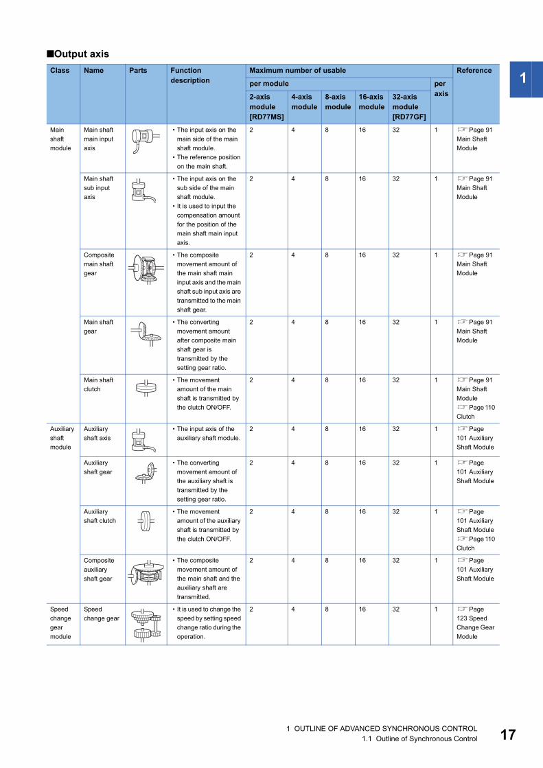
■Output axis
Class Name Parts Function description
Maximum number of usable Reference
per module per axis2-axis
module [RD77MS]
4-axis module
8-axis module
16-axis module
32-axis module[RD77GF]
Main
shaft
module
Main shaft
main input
axis
• The input axis on the
main side of the main
shaft module.
• The reference position
on the main shaft.
2 4 8 16 32 1 Page 91
Main Shaft
Module
Main shaft
sub input
axis
• The input axis on the
sub side of the main
shaft module.
• It is used to input the
compensation amount
for the position of the
main shaft main input
axis.
2 4 8 16 32 1 Page 91
Main Shaft
Module
Composite
main shaft
gear
• The composite
movement amount of
the main shaft main
input axis and the main
shaft sub input axis are
transmitted to the main
shaft gear.
2 4 8 16 32 1 Page 91
Main Shaft
Module
Main shaft
gear
• The converting
movement amount
after composite main
shaft gear is
transmitted by the
setting gear ratio.
2 4 8 16 32 1 Page 91
Main Shaft
Module
Main shaft
clutch
• The movement
amount of the main
shaft is transmitted by
the clutch ON/OFF.
2 4 8 16 32 1 Page 91
Main Shaft
Module
Page 110
Clutch
Auxiliary
shaft
module
Auxiliary
shaft axis
• The input axis of the
auxiliary shaft module.
2 4 8 16 32 1 Page
101 Auxiliary
Shaft Module
Auxiliary
shaft gear
• The converting
movement amount of
the auxiliary shaft is
transmitted by the
setting gear ratio.
2 4 8 16 32 1 Page
101 Auxiliary
Shaft Module
Auxiliary
shaft clutch
• The movement
amount of the auxiliary
shaft is transmitted by
the clutch ON/OFF.
2 4 8 16 32 1 Page
101 Auxiliary
Shaft Module
Page 110
Clutch
Composite
auxiliary
shaft gear
• The composite
movement amount of
the main shaft and the
auxiliary shaft are
transmitted.
2 4 8 16 32 1 Page
101 Auxiliary
Shaft Module
Speed
change
gear
module
Speed
change gear
• It is used to change the
speed by setting speed
change ratio during the
operation.
2 4 8 16 32 1 Page
123 Speed
Change Gear
Module
1 OUTLINE OF ADVANCED SYNCHRONOUS CONTROL1.1 Outline of Synchronous Control 17

18
■Cam data
Output
axis
module
Output axis • The cam conversion is
processed based on
the input movement
amount and the setting
cam data.The feed
current value is output
as the command to the
servo amplifier.
2 4 8 16 32 1 Page
125 Output
Axis Module
Class Name Function description Maximum number of usable
Reference
per module
Cam data Cam data • It controls the operation pattern of the output axis (two-way
operation and feed operation), which is corresponding to the
input movement amount of the output axis module.
Up to 256 [RD77MS]
Up to 1024 [RD77GF]
Page 62 CAM
FUNCTION
Class Name Parts Function description
Maximum number of usable Reference
per module per axis2-axis
module [RD77MS]
4-axis module
8-axis module
16-axis module
32-axis module[RD77GF]
1 OUTLINE OF ADVANCED SYNCHRONOUS CONTROL1.1 Outline of Synchronous Control
1
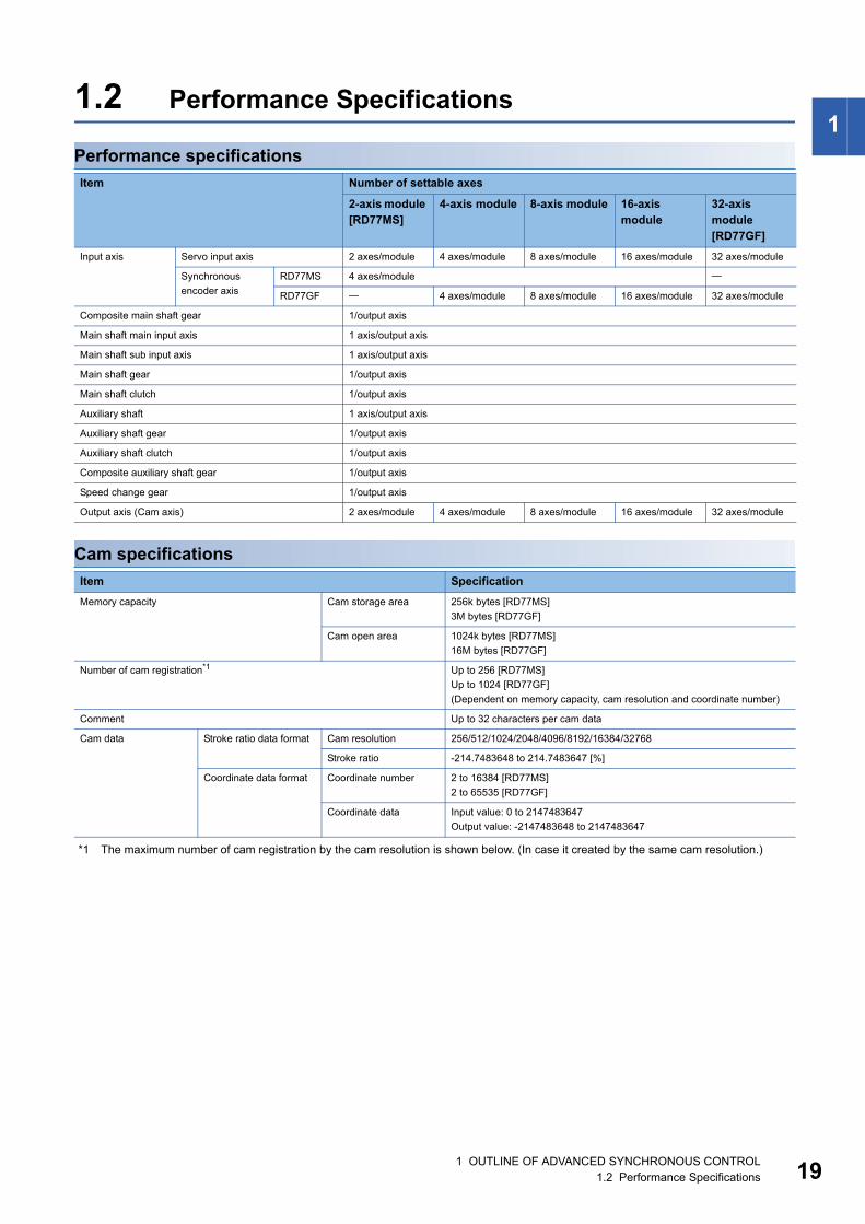
1.2 Performance SpecificationsPerformance specifications
Cam specifications
*1 The maximum number of cam registration by the cam resolution is shown below. (In case it created by the same cam resolution.)
Item Number of settable axes
2-axis module [RD77MS]
4-axis module 8-axis module 16-axis module
32-axis module[RD77GF]
Input axis Servo input axis 2 axes/module 4 axes/module 8 axes/module 16 axes/module 32 axes/module
Synchronous
encoder axis
RD77MS 4 axes/module
RD77GF 4 axes/module 8 axes/module 16 axes/module 32 axes/module
Composite main shaft gear 1/output axis
Main shaft main input axis 1 axis/output axis
Main shaft sub input axis 1 axis/output axis
Main shaft gear 1/output axis
Main shaft clutch 1/output axis
Auxiliary shaft 1 axis/output axis
Auxiliary shaft gear 1/output axis
Auxiliary shaft clutch 1/output axis
Composite auxiliary shaft gear 1/output axis
Speed change gear 1/output axis
Output axis (Cam axis) 2 axes/module 4 axes/module 8 axes/module 16 axes/module 32 axes/module
Item Specification
Memory capacity Cam storage area 256k bytes [RD77MS]
3M bytes [RD77GF]
Cam open area 1024k bytes [RD77MS]
16M bytes [RD77GF]
Number of cam registration*1 Up to 256 [RD77MS]
Up to 1024 [RD77GF]
(Dependent on memory capacity, cam resolution and coordinate number)
Comment Up to 32 characters per cam data
Cam data Stroke ratio data format Cam resolution 256/512/1024/2048/4096/8192/16384/32768
Stroke ratio -214.7483648 to 214.7483647 [%]
Coordinate data format Coordinate number 2 to 16384 [RD77MS]
2 to 65535 [RD77GF]
Coordinate data Input value: 0 to 2147483647
Output value: -2147483648 to 2147483647
1 OUTLINE OF ADVANCED SYNCHRONOUS CONTROL1.2 Performance Specifications 19

20
■Stroke ratio data format • RD77MS
• RD77GF
■Coordinate data format • RD77MS
• RD77GF
Cam resolution Maximum number of cam registration
Cam storage area Cam open area
256 256 256
512 128 256
1024 64 256
2048 32 128
4096 16 64
8192 8 32
16384 4 16
32768 2 8
Cam resolution Maximum number of cam registration
Cam storage area Cam open area
256 1024
512 1024
1024 1024
2048 1024
4096 1024
8192 512
16384 256
32768 128
Coordinate number Maximum number of cam registration
Cam storage area Cam open area
128 256 256
256 128 256
512 64 256
1024 32 128
2048 16 64
4096 8 32
8192 4 16
16384 2 8
Coordinate number Maximum number of cam registration
Cam storage area Cam open area
128 1024
256 1024
512 1024
1024 1024
2048 1024
4096 512
8192 256
16384 128
32768 64
65535 32
1 OUTLINE OF ADVANCED SYNCHRONOUS CONTROL1.2 Performance Specifications
1
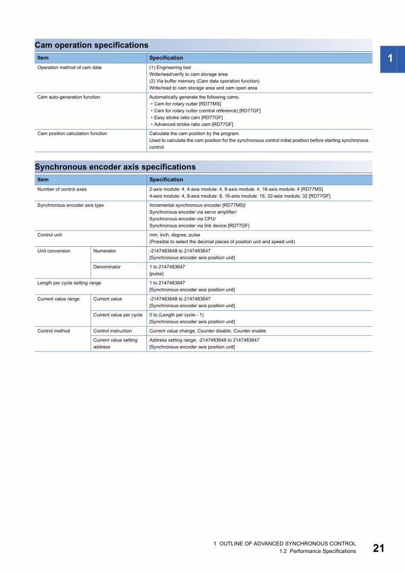
Cam operation specificationsSynchronous encoder axis specifications
Item Specification
Operation method of cam data (1) Engineering tool
Write/read/verify to cam storage area
(2) Via buffer memory (Cam data operation function)
Write/read to cam storage area and cam open area
Cam auto-generation function Automatically generate the following cams.
• Cam for rotary cutter [RD77MS]
• Cam for rotary cutter (central reference) [RD77GF]
• Easy stroke ratio cam [RD77GF]
• Advanced stroke ratio cam [RD77GF]
Cam position calculation function Calculate the cam position by the program.
Used to calculate the cam position for the synchronous control initial position before starting synchronous
control.
Item Specification
Number of control axes 2-axis module: 4, 4-axis module: 4, 8-axis module: 4, 16-axis module: 4 [RD77MS]
4-axis module: 4, 8-axis module: 8, 16-axis module: 16, 32-axis module: 32 [RD77GF]
Synchronous encoder axis type Incremental synchronous encoder [RD77MS]/
Synchronous encoder via servo amplifier/
Synchronous encoder via CPU/
Synchronous encoder via link device [RD77GF]
Control unit mm, inch, degree, pulse
(Possible to select the decimal places of position unit and speed unit)
Unit conversion Numerator -2147483648 to 2147483647
[Synchronous encoder axis position unit]
Denominator 1 to 2147483647
[pulse]
Length per cycle setting range 1 to 2147483647
[Synchronous encoder axis position unit]
Current value range Current value -2147483648 to 2147483647
[Synchronous encoder axis position unit]
Current value per cycle 0 to (Length per cycle - 1)
[Synchronous encoder axis position unit]
Control method Control instruction Current value change, Counter disable, Counter enable
Current value setting
address
Address setting range: -2147483648 to 2147483647
[Synchronous encoder axis position unit]
1 OUTLINE OF ADVANCED SYNCHRONOUS CONTROL1.2 Performance Specifications 21
22
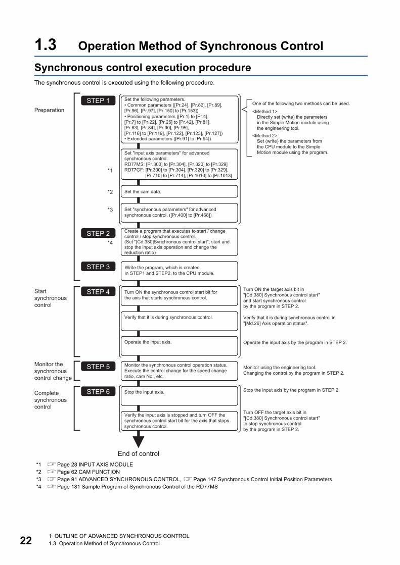
1.3 Operation Method of Synchronous Control
Synchronous control execution procedureThe synchronous control is executed using the following procedure.
*1 Page 28 INPUT AXIS MODULE*2 Page 62 CAM FUNCTION*3 Page 91 ADVANCED SYNCHRONOUS CONTROL, Page 147 Synchronous Control Initial Position Parameters*4 Page 181 Sample Program of Synchronous Control of the RD77MS
PreparationSTEP 1
End of control
*1
*2
*3
STEP 2*4
STEP 3
STEP 4Startsynchronouscontrol
STEP 5
STEP 6Completesynchronouscontrol
Monitor thesynchronouscontrol change
Set the cam data.
Set "synchronous parameters" for advancedsynchronous control. ([Pr.400] to [Pr.468])
Create a program that executes to start / changecontrol / stop synchronous control. (Set "[Cd.380]Synchronous control start", start andstop the input axis operation and change thereduction ratio)
Turn ON the synchronous control start bit forthe axis that starts synchronous control.
Operate the input axis.
Monitor the synchronous control operation status.Execute the control change for the speed changeratio, cam No., etc.
Stop the input axis.
Verify the input axis is stopped and turn OFF thesynchronous control start bit for the axis that stopssynchronous control.
Verify that it is during synchronous control.
Turn ON the target axis bit in"[Cd.380] Synchronous control start"and start synchronous controlby the program in STEP 2.
Operate the input axis by the program in STEP 2.
Verify that it is during synchronous control in"[Md.26] Axis operation status".
Monitor using the engineering tool.Changing the control by the program in STEP 2.
Turn OFF the target axis bit in"[Cd.380] Synchronous control start"to stop synchronous controlby the program in STEP 2.
Stop the input axis by the program in STEP 2.
Write the program, which is createdin STEP1 and STEP2, to the CPU module.
One of the following two methods can be used.
<Method 1>Directly set (write) the parameters in the Simple Motion module using the engineering tool.
<Method 2>Set (write) the parameters from the CPU module to the Simple Motion module using the program.
Set the following parameters.• Common parameters ([Pr.24], [Pr.82], [Pr.89],[Pr.96], [Pr.97], [Pr.150] to [Pr.153])• Positioning parameters ([Pr.1] to [Pr.4],[Pr.7] to [Pr.22], [Pr.25] to [Pr.42], [Pr.81],[Pr.83], [Pr.84], [Pr.90], [Pr.95],[Pr.116] to [Pr.119], [Pr.122], [Pr.123], [Pr.127])• Extended parameters ([Pr.91] to [Pr.94])
Set "input axis parameters" for advanced synchronous control.RD77MS: [Pr.300] to [Pr.304], [Pr.320] to [Pr.329] RD77GF: [Pr.300] to [Pr.304], [Pr.320] to [Pr.329], [Pr.710] to [Pr.714], [Pr.1010] to [Pr.1013]
1 OUTLINE OF ADVANCED SYNCHRONOUS CONTROL1.3 Operation Method of Synchronous Control

1
Precautions
• Mechanical elements such as limit switches are considered as already installed.
• Parameter settings for positioning control apply for all axes with the Simple Motion module.
• Be sure to execute the home position return when the home position return request flag is ON.
Starting/ending for synchronous controlSet the advanced synchronous control parameters for each output axis to start synchronous control.
The status changes to synchronous control after the advanced synchronous control parameters are analyzed at the start of
synchronous control, and the output axes synchronize with input axis operations.
Synchronous control system control data
*1 The range from axis 1 to 2 is valid in the 2-axis module, from axis 1 to 4 is valid in the 4-axis module, from axis 1 to 8 is valid in the 8-axis module, from axis 1 to 16 is valid in the 16-axis module, and from axis 1 to 32 is valid in the 32-axis module.
Setting item Setting details Setting value Default value
Buffer memory address
Axis 1 to axis 16
Axis 17 to axis 32
[Cd.380]
Synchronous
control start
• Synchronous control begins if the target axis bit
is turned ON.
• Synchronous control ends if the bit is turned
OFF during synchronous control.
Fetch cycle: Operation cycle
■Set the target axis in bit.
Set with the following two buffer
memory addresses.
• Buffer memory address: 36320
(bit0: axis 1 to bit15: axes 16*1)
• Buffer memory address: 1036320
(bit0: axes 17 to bit15: axes 32*1)
OFF : Synchronous control end
ON : Synchronous control start
0 36320 1036320
Standby (0) Analyzing (5) Standby (0)Synchronous control (15)
t
t
t
BUSY signal
[Cd.380] Synchronous control start (Target axis bit)
[Md.26] Axis operation status
[Md.20] Feed current value
[Md.321] Synchronous encoder axis current value per cycle
[Md.407] Cam axis current value per cycle
b0b15 b12 b8 b4
b0b15 b12 b8 b4
Buffer memory address: 36320
Axis 1 to 16
Axis 17 to 32
Buffer memory address: 1036320
1 OUTLINE OF ADVANCED SYNCHRONOUS CONTROL1.3 Operation Method of Synchronous Control 23
24
Starting method for synchronous controlSynchronous control can be started by turning the target axis bit from OFF to ON in "[Cd.380] Synchronous control start" after
setting the advanced synchronous control parameters.
"5: Analyzing" is set in "[Md.26] Axis operation status" at the synchronous control start, and the advanced synchronous control
parameters are analyzed. The BUSY signal turns ON after completion of analysis, and "15: Synchronous control" is set in
"[Md.26] Axis operation status".
Start the input axis operation after confirming that "15: Synchronous control" is set in "[Md.26] Axis operation status".
Ending method for synchronous controlSynchronous control can be ended by turning the target axis bit from ON to OFF in "[Cd.380] Synchronous control start" after
the input axis operation is stopped.
The BUSY signal turns OFF at the synchronous control end, and "0: Standby" is set in "[Md.26] Axis operation status" at the
output axis stop.
Synchronous control can also be ended by turning the target axis bit from ON to OFF in "[Cd.380] Synchronous control start"
during the input axis operation. However, it is recommended to end after stopping the input axis operation since the output
axis stops immediately.
Refer to the following for the stop operation of output axis at the synchronous control end.
Page 26 Stop operation of output axis
Starting historyThe starting history is updated when starting synchronous control. "9020: Synchronous control operation" is stored in "[Md.4]
Start No.".
Status when starting synchronous controlThe following bits in "[Md.31] Status" are turned OFF when starting synchronous control in the same way as for the positioning
control start.
Bit Details
b0 In speed control flag
b1 Speed-position switching latch flag
b2 Command in-position flag
b4 Home position return complete flag
b5 Position-speed switching latch flag
b10 Speed change 0 flag
1 OUTLINE OF ADVANCED SYNCHRONOUS CONTROL1.3 Operation Method of Synchronous Control

1
• If bit for multiple axes are turned ON simultaneously in "[Cd.380] Synchronous control start", control is notstarted simultaneously since the analysis is processed for each axis in numerical order. When the multiple
axes must be started simultaneously, start the input axis operation after confirming that all axes are
configured for the synchronous control.
• If the input axis operates during the analysis at the synchronous control start, the movement amount of the
input axis is reflected immediately after the synchronous control start. The output axis might rapidly
accelerate depending on the movement amount of the input axis. Start the input axis operation after
confirming that are configured for synchronous control.
• The analysis process for synchronous control start might take time depending on the setting of the
advanced synchronous control parameters. (When "0: Cam axis current value per cycle restoration" is set in
"[Pr.462] Cam axis position restoration object" and the cam (cam resolution: 32768) is searched: About 26
ms, When "0: Cam axis current value per cycle restoration" is set in "[Pr.462] Cam axis position restoration
object" and the cam (cam resolution: 256) is searched: About 0.4 ms [RD77MS], about 0.5 ms [RD77GF])
Set "1: Cam reference position restoration" or "2: Cam axis feed current value restoration" in "[Pr.462] Cam
axis position restoration object" to start synchronous control at high speed.
• When the advanced synchronous control parameters are set to the value outside the setting range, the
synchronous control does not start, and the input axis error No. is stored in the monitor data.
1 OUTLINE OF ADVANCED SYNCHRONOUS CONTROL1.3 Operation Method of Synchronous Control 25

26
Stop operation of output axisIf the following causes occur in stopping the output axis during synchronous control, synchronous control is completed after
stops processing for the output axis (BUSY signal is OFF, axis operation status is standby).
Synchronous alignment must be executed for the output axis to restart the synchronous control (Page 125 Output Axis
Module).
*1 Refer to the following for details.MELSEC iQ-R Simple Motion Module User's Manual (Application)
Immediate stopThe operation stops without decelerate. The Simple Motion module immediately stops the command, but the operation will
coast for the droop pulses accumulated in the deviation counter of the servo amplifier.
Stop cause Stop process
The target axis bit of "[Cd.380] Synchronous control start" is turned from ON to OFF. Immediate stop
Software stroke limit error occurrence
Emergency stop
Forced stop
Stop group1 to 3*1 (Stop with hardware stroke limit or stop command) Deceleration stop
t
BUSY signal
[Md.22] Feedrate
t
t
Immediate stop
[Md.407] Cam axis current value per cycle
[Md.20] Feed current value (Cam operation)
[Cd.380] Synchronous control start (Target axis bit)
1 OUTLINE OF ADVANCED SYNCHRONOUS CONTROL1.3 Operation Method of Synchronous Control

1
Deceleration stopThe output axis stops with deceleration according to the setting in "[Pr.37] Stop group 1 rapid stop selection" to "[Pr.39] Stopgroup 3 rapid stop selection". The deceleration time is set in "[Pr.446] Synchronous control deceleration time" for deceleration
stop, and in "[Pr.36] Rapid stop deceleration time" for rapid stop. The slope of deceleration is as follows.
The cam axis current value per cycle is not updated, and only the feed current value is updated, since the deceleration stop
begins. Therefore, the path of the feed current value is drawn regardless the cam operation with deceleration stop.
The input axis must be stopped when the output axis is stop synchronizing with the input axis.
Slope of deceleration =[Pr.8] Speed limit value
Deceleration time (Rapid stop deceleration time)
t
Axis stop signal
[Md.22] Feedrate
t
t
BUSY signal
Deceleration stop
[Md.407] Cam axis current value per cycle
[Cd.380] Synchronous control start (Target axis bit)
[Md.20] Feed current value (Cam operation)
1 OUTLINE OF ADVANCED SYNCHRONOUS CONTROL1.3 Operation Method of Synchronous Control 27
28
2 INPUT AXIS MODULE
The settings for the parameter and monitor data for the input axis module that used with synchronous control are explained in
this chapter.
Refer to the following for details on the connection and control for the servo amplifier and the synchronous encoder that are
used for input axis module.
MELSEC iQ-R Simple Motion Module User's Manual (Application)
2.1 Servo Input Axis
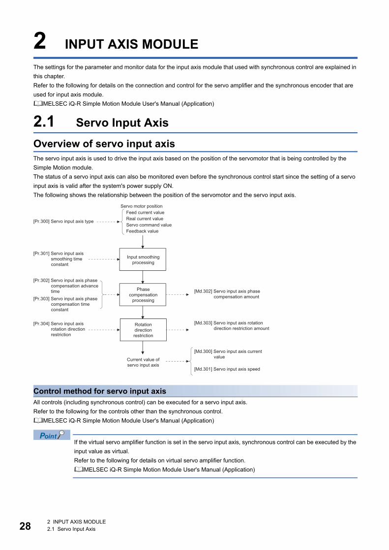
Overview of servo input axisThe servo input axis is used to drive the input axis based on the position of the servomotor that is being controlled by the
Simple Motion module.
The status of a servo input axis can also be monitored even before the synchronous control start since the setting of a servo
input axis is valid after the system's power supply ON.
The following shows the relationship between the position of the servomotor and the servo input axis.
Control method for servo input axisAll controls (including synchronous control) can be executed for a servo input axis.
Refer to the following for the controls other than the synchronous control.
MELSEC iQ-R Simple Motion Module User's Manual (Application)
If the virtual servo amplifier function is set in the servo input axis, synchronous control can be executed by the
input value as virtual.
Refer to the following for details on virtual servo amplifier function.
MELSEC iQ-R Simple Motion Module User's Manual (Application)
Input smoothingprocessing
Phasecompensation
processing
Rotationdirectionrestriction
Feed current valueReal current valueServo command valueFeedback value
Servo motor position
Current value ofservo input axis
[Pr.300] Servo input axis type
[Pr.301] Servo input axis smoothing time constant
[Pr.302] Servo input axis phase compensation advance time
[Md.303] Servo input axis rotation direction restriction amount
[Md.300] Servo input axis current value
[Md.301] Servo input axis speed
[Md.302] Servo input axis phase compensation amount[Pr.303] Servo input axis phase
compensation time constant
[Pr.304] Servo input axis rotation direction restriction
2 INPUT AXIS MODULE2.1 Servo Input Axis

2
If "1: Feed current value" or "2: Real current value" is set in "[Pr.300] Servo input axis type", set "1: Update
feed current value" in "[Pr.21] Feed current value during speed control" to start the speed position change
control. If "0: Do not update feed current value" or "2: Clear feed current value to zero" is set in [Pr.21], the
error "Speed-position switching control start in servo input axis not possible" (error code: 1BA7H) will occur
and the control will not start.
Units for the servo input axisThe position units and speed units for the servo input axis are shown below for the setting "[Pr.300] Servo input axis type" and
"[Pr.1] Unit setting".
■Servo input axis position units
■Servo input axis speed units
*1 This will be the speed unit " 10-2 degree/min" (Range: -21474836.48 to 21474836.47 [degree/min]), when "[Pr.83] Speed control 10 multiplier setting for degree axis" is valid.
• When "1: Feed current value" or "3: Servo command value" is set in "[Pr.300] Servo input axis type", and the
servo input axis becomes servo OFF by the servo alarm or forced stop, the amount of value change may be
large. This can be prevented by setting "2: Real current value" or "4: Feedback value" in "[Pr.300] Servo
input axis type".
• When a home position return for the axis where "1: Feed current value" or "2: Real current value" is set in
"[Pr.300] Servo input axis type" is performed, if the servo input axis operation during home position return is
used as the input value, the input is stopped in the midway of home position return. When the servo input
axis operation during home position return is used as the input value, set "3: Servo command value" or "4:
Feedback value" in "[Pr.300] Servo input axis type".
Setting value of "[Pr.300] Servo input axis type"
Setting value of "[Pr.1] Unit setting"
Servo input axis position unit
Range
1: Feed current value
2: Real current value
0: mm 10 -4 mm
(10-1 m)
-214748.3648 to 214748.3647 [mm]
(-214748364.8 to 214748364.7 [m])
1: inch 10-5 inch -21474.83648 to 21474.83647 [inch]
2: degree 10-5 degree -21474.83648 to 21474.83647 [degree]
3: pulse pulse -2147483648 to 2147483647 [pulse]
3: Servo command value
4: Feedback value
pulse -2147483648 to 2147483647 [pulse]
Setting value of "[Pr.300] Servo input axis type"
Setting value of "[Pr.1] Unit setting"
Servo input axis speed unit Range
1: Feed current value
2: Real current value
0: mm 10-2 mm/min -21474836.48 to 21474836.47 [mm/min]
1: inch 10-3 inch/min -2147483.648 to 2147483.647 [inch/min]
2: degree 10-3 degree/min*1 -2147483.648 to 2147483.647 [degree/min]*1
3: pulse pulse/s -2147483648 to 2147483647 [pulse/s]
3: Servo command value
4: Feedback value
pulse/s -2147483648 to 2147483647 [pulse/s]
2 INPUT AXIS MODULE2.1 Servo Input Axis 29

30
Servo input axis parametersn: Axis No. - 1 (n: Axis No. - 17 for axis 17 to axis 32)
*1 Set the value as follows in a program.0 to 32767: Set as a decimal.32768 to 65535: Convert into a hexadecimal and set.
[Pr.300] Servo input axis typeSet the current value type to be generated of the input value for the servo input axis.
Setting item Setting details Setting value Default value
Buffer memory address
Axis 1 to axis 16
Axis 17 to axis 32
[Pr.300]
Servo input axis type
• Set the current value type to be
generated of the input value for
the servo input axis.
Fetch cycle: At power supply ON
■Set in decimal.
0: Invalid
1: Feed current value
2: Real current value
3: Servo command value
4: Feedback value
0 32800+10n 1032800+10n
[Pr.301]
Servo input axis smoothing time
constant
• Set to smooth the input value.
Fetch cycle: At power supply ON
■Set in decimal.
0 to 5000 [ms]
0 32801+10n 1032801+10n
[Pr.302]
Servo input axis phase
compensation advance time
• Set the time to advance or delay
the phase.
Fetch cycle: Operation cycle
■Set in decimal.
-2147483648 to 2147483647 [s]
0 32802+10n
32803+10n
1032802+10n
1032803+10n
[Pr.303]
Servo input axis phase
compensation time constant
• Set the time constant to affect the
phase compensation.
Fetch cycle: At power supply ON
■Set in decimal.
0 to 65535 [ms]*110 32804+10n 1032804+10n
[Pr.304]
Servo input axis rotation direction
restriction
• Set this parameter to restrict the
input movement amount to one
direction.
Fetch cycle: At power supply ON
■Set in decimal.
0: Without rotation direction
restriction
1: Enable only for current value
increase direction
2: Enable only for current value
decrease direction
0 32805+10n 1032805+10n
Setting value Details
0: Invalid Servo input axis is invalid.
1: Feed current value Generate the input value based on "[Md.20] Feed current value".
2: Real current value Generate the input value based on the real current value, which is converted into units of the encoder feedback pulses
from the servo amplifier.
3: Servo command value Generate the input value based on the command pulse for the servo amplifier (a value that the feed current value is
converted into encoder pulse units).
4: Feedback value Generate the input value based on the encoder feedback pulse from the servo amplifier.
Simple Motion module
Unit → Pulse conversion(Backlash compensation)
1: Feed current value
3: Servo command value
2: Real current value Pulse → Unit conversion
4: Feedback value
Servoamplifier
2 INPUT AXIS MODULE2.1 Servo Input Axis
2
[Pr.301] Servo input axis smoothing time constantSet the averaging time to execute a smoothing process for the input movement amount from the servo input axis.
The smoothing process can moderate speed fluctuation, when the "Real current value" or "Feedback value" is used as input
values. The input response is delayed depending on the time corresponding to the setting by smoothing process setting.
[Pr.302] Servo input axis phase compensation advance timeSet the time to advance or delay the phase (input response) of the servo input axis.
Refer to the following for the delay time inherent to the system using the servo input axis.
Page 140 Phase Compensation Function
If the setting time is too long, the system experiences overshoot or undershoot at acceleration/deceleration of the input speed.
In this case, set longer time to affect the phase compensation amount in "[Pr.303] Servo input axis phase compensation time
constant".
[Pr.303] Servo input axis phase compensation time constantSet the time constant to affect the phase compensation amount for the first order delay.
63 [%] of the phase compensation amount are reflected in the time constant setting.
Setting value Details
1 to 2147483647 [s] Advance the phase (input response) according to the setting time.
0 [s] Do not execute phase compensation.
-2147483648 to -1 [s] Delay the phase (input response) according to the setting time.
[Pr.301] Servo input axis smoothing time constant
[Pr.301] Servo input axis smoothing time constant
t
t
Input value speedbefore smoothing
Input value speedafter smoothing
Averaging bysmoothing time constant
t
Servo input axiscurrent value
t
t
t63%63%
Speed before phasecompensation
Speed after phasecompensation
Current value afterphase compensation
Current value before phase compensation
Speed beforephase compensation
[Pr.302] Servo input axis phase compensation advance time
[Md.302] Servo input axis phase compensation amount
×[Md.302] Servo input axis
phase compensation amount
[Pr.303] Servo input axis phase compensation time constant
[Pr.303] Servo input axis phase compensation time constant
2 INPUT AXIS MODULE2.1 Servo Input Axis 31

32
[Pr.304] Servo input axis rotation direction restrictionSet this parameter to restrict the input movement amount for the servo input axis to one direction.
This helps to avoid reverse operation caused by such as machine vibration when "Real current value" or "Feedback value" is
used as input values.
The input movement amount in the reverse direction of the enabled direction accumulates as a rotation direction restricted
amount, and will be reflected when the input movement amount moves in the enabled direction again. Therefore, the current
value of servo input does not deviate when the reverse operation is repeated.
The rotation direction restricted amount is set to 0 when the following operations are executed for the servo input axis.
• A servo amplifier is connected
• The home position return is executed
• The current value is changed
Setting value Details
0: Without rotation direction restriction Rotation direction restriction is not executed.
1: Enable only for current value increase direction Enable only the input movement amount in the increasing direction of the
servo input axis current value.
2: Enable only for current value decrease direction Enable only the input movement amount in the decreasing direction of the
servo input axis current value.
t
Speed before rotationdirection restriction
t
t
The input movement amount is accumulated as a rotationdirection restricted amount, and will be reflected whenthe input movement amount in the enabled direction.
For "1: Enable only for current value increase direction" is set in "[Pr.304] Servo input axis rotation direction restriction".
[Md.301] Servo input axis speed (Speed after rotation direction restriction)
[Md.303] Servo input axis rotation direction restriction amount
2 INPUT AXIS MODULE2.1 Servo Input Axis
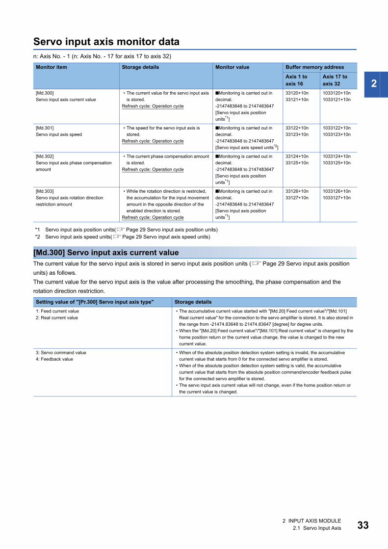
2
Servo input axis monitor datan: Axis No. - 1 (n: Axis No. - 17 for axis 17 to axis 32)
*1 Servo input axis position units(Page 29 Servo input axis position units)*2 Servo input axis speed units(Page 29 Servo input axis speed units)
[Md.300] Servo input axis current valueThe current value for the servo input axis is stored in servo input axis position units (Page 29 Servo input axis position
units) as follows.
The current value for the servo input axis is the value after processing the smoothing, the phase compensation and the
rotation direction restriction.
Monitor item Storage details Monitor value Buffer memory address
Axis 1 to axis 16
Axis 17 to axis 32
[Md.300]
Servo input axis current value
• The current value for the servo input axis
is stored.
Refresh cycle: Operation cycle
■Monitoring is carried out in
decimal.
-2147483648 to 2147483647
[Servo input axis position
units*1]
33120+10n
33121+10n
1033120+10n
1033121+10n
[Md.301]
Servo input axis speed
• The speed for the servo input axis is
stored.
Refresh cycle: Operation cycle
■Monitoring is carried out in
decimal.
-2147483648 to 2147483647
[Servo input axis speed units*2]
33122+10n
33123+10n
1033122+10n
1033123+10n
[Md.302]
Servo input axis phase compensation
amount
• The current phase compensation amount
is stored.
Refresh cycle: Operation cycle
■Monitoring is carried out in
decimal.
-2147483648 to 2147483647
[Servo input axis position
units*1]
33124+10n
33125+10n
1033124+10n
1033125+10n
[Md.303]
Servo input axis rotation direction
restriction amount
• While the rotation direction is restricted,
the accumulation for the input movement
amount in the opposite direction of the
enabled direction is stored.
Refresh cycle: Operation cycle
■Monitoring is carried out in
decimal.
-2147483648 to 2147483647
[Servo input axis position
units*1]
33126+10n
33127+10n
1033126+10n
1033127+10n
Setting value of "[Pr.300] Servo input axis type" Storage details
1: Feed current value
2: Real current value
• The accumulative current value started with "[Md.20] Feed current value"/"[Md.101]
Real current value" for the connection to the servo amplifier is stored. It is also stored in
the range from -21474.83648 to 21474.83647 [degree] for degree units.
• When the "[Md.20] Feed current value"/"[Md.101] Real current value" is changed by the
home position return or the current value change, the value is changed to the new
current value.
3: Servo command value
4: Feedback value
• When of the absolute position detection system setting is invalid, the accumulative
current value that starts from 0 for the connected servo amplifier is stored.
• When of the absolute position detection system setting is valid, the accumulative
current value that starts from the absolute position command/encoder feedback pulse
for the connected servo amplifier is stored.
• The servo input axis current value will not change, even if the home position return or
the current value is changed.
2 INPUT AXIS MODULE2.1 Servo Input Axis 33

34
[Md.301] Servo input axis speedThe speed for the servo input axis is stored in servo input axis speed units (Page 29 Servo input axis speed units).
The speed for the servo input axis is the value after processing smoothing, phase compensation, and rotation direction
restriction.
[Md.302] Servo input axis phase compensation amountThe phase compensation amount for a servo input axis is stored in servo input axis position units (Page 29 Servo input
axis position units).
The phase compensation amount for a servo input axis is the value after processing smoothing and phase compensation.
[Md.303] Servo input axis rotation direction restriction amountWhile the rotation direction is restricted for a servo input axis, the accumulation for input movement amount in the opposite
direction of the enabled direction is stored in servo input axis position units (Page 29 Servo input axis position units) as
follows.
Rotation direction restriction is processed after phase compensation processing. Therefore, if undershoot occurs from phase
compensation during deceleration stop, the rotation direction restriction amount might remain.
Setting value of "[Pr.304] Servo input axis rotation direction restriction"
Storage details
1: Enable only for current value increase direction A negative accumulation is stored during rotation direction restriction.
0 is stored if there is no restriction.
2: Enable only for current value decrease direction A positive accumulation is stored during rotation direction restriction.
0 is stored if there is no restriction.
2 INPUT AXIS MODULE2.1 Servo Input Axis

2
2.2 Synchronous Encoder Axis
Overview of synchronous encoder axisThe synchronous encoder is used to drive the input axis based on input pulse from a synchronous encoder that is connected
externally.
The status of a synchronous encoder axis can also be monitored after the system's power supply turns ON.
Input smoothingprocessing
Phasecompensation
processing
Rotationdirectionrestriction
Current valueof synchronousencoder axis
Unit conversion
Current value change
Input pulse ofsynchronous
encoder
[Md.323] Synchronous encoder axis phase compensation amount
[Md.324] Synchronous encoder axis rotation direction restriction amount
[Md.320] Synchronous encoder axis current value
[Md.321] Synchronous encoder axis current value per cycle
[Md.322] Synchronous encoder axis speed
[Pr.321] Synchronous encoder axis unit setting
[Pr.322] Synchronous encoder axis unit conversion: Numerator
[Pr.323] Synchronous encoder axis unit conversion: Denominator
[Pr.325] Synchronous encoder axis smoothing time constant
[Pr.326] Synchronous encoder axis phase compensation advance time
[Pr.327] Synchronous encoder axis phase compensation time constant
[Pr.328] Synchronous encoder axis rotation direction restriction
[Pr.324] Synchronous encoder axis length per cycle
[Pr.24] Manual pulse generator/Incremental synchronous encoder input selection
[Pr.89] Manual pulse generator/Incremental synchronous encoder input type selection
[Pr.151] Manual pulse generator/Incremental synchronous encoder input logic selection
[Pr.320] Synchronous encoder axis type
[Pr.329] Resolution of synchronous encoder via CPU
[Pr.710], [Pr.711], [Pr.712], [Pr.713], [Pr.714]Synchronous encoder axis[Pr.1010], [Pr.1011], [Pr.1012], [Pr.1013]Synchronous encoder axis start request
Counter disable/Counter enable
2 INPUT AXIS MODULE2.2 Synchronous Encoder Axis 35
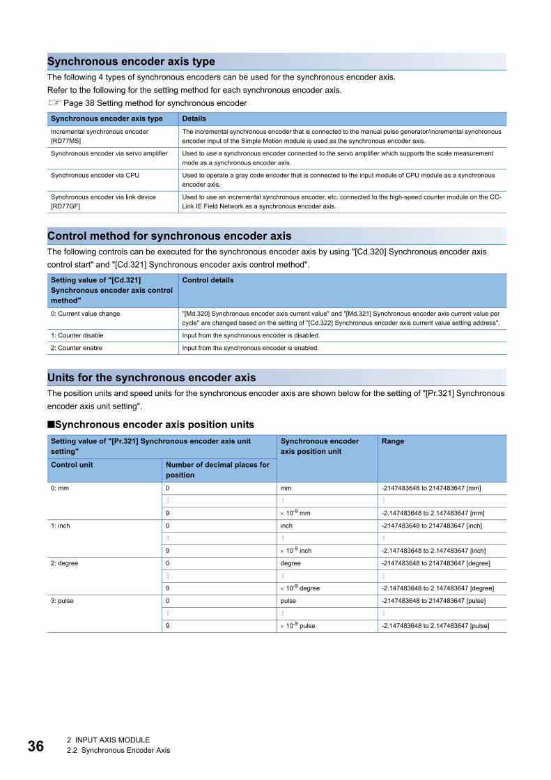
36
Synchronous encoder axis typeThe following 4 types of synchronous encoders can be used for the synchronous encoder axis.
Refer to the following for the setting method for each synchronous encoder axis.
Page 38 Setting method for synchronous encoder
Control method for synchronous encoder axisThe following controls can be executed for the synchronous encoder axis by using "[Cd.320] Synchronous encoder axis
control start" and "[Cd.321] Synchronous encoder axis control method".
Units for the synchronous encoder axisThe position units and speed units for the synchronous encoder axis are shown below for the setting of "[Pr.321] Synchronous
encoder axis unit setting".
■Synchronous encoder axis position units
Synchronous encoder axis type Details
Incremental synchronous encoder
[RD77MS]
The incremental synchronous encoder that is connected to the manual pulse generator/incremental synchronous
encoder input of the Simple Motion module is used as the synchronous encoder axis.
Synchronous encoder via servo amplifier Used to use a synchronous encoder connected to the servo amplifier which supports the scale measurement
mode as a synchronous encoder axis.
Synchronous encoder via CPU Used to operate a gray code encoder that is connected to the input module of CPU module as a synchronous
encoder axis.
Synchronous encoder via link device
[RD77GF]
Used to use an incremental synchronous encoder, etc. connected to the high-speed counter module on the CC-
Link IE Field Network as a synchronous encoder axis.
Setting value of "[Cd.321] Synchronous encoder axis control method"
Control details
0: Current value change "[Md.320] Synchronous encoder axis current value" and "[Md.321] Synchronous encoder axis current value per
cycle" are changed based on the setting of "[Cd.322] Synchronous encoder axis current value setting address".
1: Counter disable Input from the synchronous encoder is disabled.
2: Counter enable Input from the synchronous encoder is enabled.
Setting value of "[Pr.321] Synchronous encoder axis unit setting"
Synchronous encoder axis position unit
Range
Control unit Number of decimal places for position
0: mm 0 mm -2147483648 to 2147483647 [mm]
9 10-9 mm -2.147483648 to 2.147483647 [mm]
1: inch 0 inch -2147483648 to 2147483647 [inch]
9 10-9 inch -2.147483648 to 2.147483647 [inch]
2: degree 0 degree -2147483648 to 2147483647 [degree]
9 10-9 degree -2.147483648 to 2.147483647 [degree]
3: pulse 0 pulse -2147483648 to 2147483647 [pulse]
9 10-9 pulse -2.147483648 to 2.147483647 [pulse]
2 INPUT AXIS MODULE2.2 Synchronous Encoder Axis
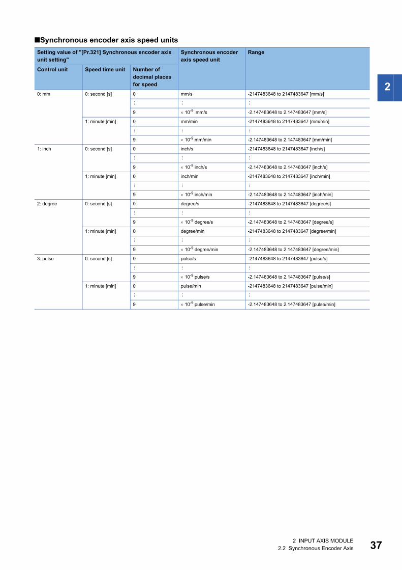
2
■Synchronous encoder axis speed units
Setting value of "[Pr.321] Synchronous encoder axis unit setting"
Synchronous encoder axis speed unit
Range
Control unit Speed time unit Number of decimal placesfor speed
0: mm 0: second [s] 0 mm/s -2147483648 to 2147483647 [mm/s]
9 10-9 mm/s -2.147483648 to 2.147483647 [mm/s]
1: minute [min] 0 mm/min -2147483648 to 2147483647 [mm/min]
9 10-9 mm/min -2.147483648 to 2.147483647 [mm/min]
1: inch 0: second [s] 0 inch/s -2147483648 to 2147483647 [inch/s]
9 10-9 inch/s -2.147483648 to 2.147483647 [inch/s]
1: minute [min] 0 inch/min -2147483648 to 2147483647 [inch/min]
9 10-9 inch/min -2.147483648 to 2.147483647 [inch/min]
2: degree 0: second [s] 0 degree/s -2147483648 to 2147483647 [degree/s]
9 10-9 degree/s -2.147483648 to 2.147483647 [degree/s]
1: minute [min] 0 degree/min -2147483648 to 2147483647 [degree/min]
9 10-9 degree/min -2.147483648 to 2.147483647 [degree/min]
3: pulse 0: second [s] 0 pulse/s -2147483648 to 2147483647 [pulse/s]
9 10-9 pulse/s -2.147483648 to 2.147483647 [pulse/s]
1: minute [min] 0 pulse/min -2147483648 to 2147483647 [pulse/min]
9 10-9 pulse/min -2.147483648 to 2.147483647 [pulse/min]
2 INPUT AXIS MODULE2.2 Synchronous Encoder Axis 37

38
Setting method for synchronous encoder
Incremental synchronous encoder [RD77MS]
■Setting methodConnect the synchronous encoder to the "Manual pulse generator/Incremental synchronous encoder input" of the Simple
Motion module.
Set the input method for the incremental synchronous encoder signal using the following parameters. (It may be common to
use the same set up for the manual pulse generator input.)
• "[Pr.24] Manual pulse generator/Incremental synchronous encoder input selection"
• "[Pr.89] Manual pulse generator/Incremental synchronous encoder input type selection"
• "[Pr.151] Manual pulse generator/Incremental synchronous encoder input logic selection"
The synchronous encoder axis operates completely independently with the manual pulse generator operation.
The parameter and control data for the manual pulse generator operation except the 3 parameters listed
above has not influence on control of synchronous encoder axis. Therefore, they can also be controlled
simultaneously by common input pulses.
When the synchronous encoder axis connection is valid after the system's power supply is ON, it will be "Synchronous
encoder axis current value = 0", "Synchronous encoder axis current value per cycle = 0" and "Counter enabling status".
■Setting exampleThe following shows an example for setting an incremental synchronous encoder as synchronous encoder axis 2 of the
Simple Motion module.
Set "1: Incremental synchronous encoder" in "[Pr.320] Synchronous encoder axis type" for the synchronous encoder axis 2.
And, set the input method for incremental synchronous encoder signal in the following parameters.
• "[Pr.24] Manual pulse generator/Incremental synchronous encoder input selection": "0: A-phase/B-phase multiplied by 4"
• "[Pr.89] Manual pulse generator/Incremental synchronous encoder input type selection": "0: Differential output type"
• "[Pr.151] Manual pulse generator/Incremental synchronous encoder input logic selection": "0: Differential output type"
RD77MS4ERRRUN
AX3
4 2
1AX
RD77MS
Axis 1 Axis 2 Axis 3
Synchronous encoder axis 2
Incrementalsynchronousencoder
2 INPUT AXIS MODULE2.2 Synchronous Encoder Axis

2
Synchronous encoder via servo amplifierThere are restrictions in the function and the encoder that can be used by the version of the servo amplifier.
■Setting methodUsed to use a synchronous encoder connected to the servo amplifier which supports the scale measurement mode as a
synchronous encoder axis.
The following servo amplifiers can be used. The servo amplifier must support the scale measurement function.
• MR-J4-B-RJ [RD77MS]
• MR-J4-GF-RJ [RD77GF]
Only a rotary encoder can be connected. Refer to the following servo amplifier instruction manuals for the version of the servo
amplifier which supports the scale measurement function and the rotary encoder which can be used.
SSCNET/H Interface AC Servo MR-J4-_B_(-RJ) Servo Amplifier Instruction Manual [RD77MS]
MR-J4-_GF_(-RJ) Servo Amplifier Instruction Manual (Motion Mode) [RD77GF]
A synchronous encoder connected to the specified servo amplifier axis can be used by the following settings.
*1 The range from axis 1 to 2 is valid in the 2-axis module, from axis 1 to 4 is valid in the 4-axis module, from axis 1 to 8 is valid in the 8-axis module, from axis 1 to 16 is valid in the 16-axis module, and from axis 1 to 32 is valid in the 32-axis module.
When "1_ _ _H" is set in the servo parameter "Scale measurement mode selection (PA22)", the synchronous encoder axis
current value and the synchronous encoder axis current value per cycle are restored after the servo amplifier axis is
connected. Therefore, connection becomes valid, and will be on the counter enabling status. (The current value setting by
current value change is required beforehand.)
When "2_ _ _H" is set in the servo parameter "Scale measurement mode selection (PA22)", "0" is set to the initial value of the
synchronous encoder axis current value and the synchronous encoder axis current value per cycle after the servo amplifier
axis is connected. Therefore, connection becomes valid, and will be on the counter enabling status.
If the corresponding servo amplifier axis is not connected, the connection of the synchronous encoder axis will be invalid.
When "1_ _ _H" is set in the servo parameter "Scale measurement mode selection (PA22)" and the
synchronous encoder movement amount (encoder pulse units) on disconnection or during the power supply
OFF exceeds "2147483647" or "-2147483648", the synchronous encoder axis current value is restored with
its opposite sign.
Setting item Setting method
Synchronous encoder axis
setting
Set "101 to 116: Synchronous encoder via servo amplifier (Connectable servo amplifier: axis 1 to axis 32*1)" in "[Pr.320]
Synchronous encoder axis type".
[Setting method of Simple Motion Module Setting Function]
Set the synchronous encoder axis parameter according to the setting below.
• "[Pr.320] Type"
101: Synchronous encoder via servo amplifier
• "[Pr.320] Axis No. of connected servo amplifier"
Axis No. of servo amplifier to connect
Encoder type setting (Absolute/
Incremental)
Set the servo parameter "Scale measurement mode selection (PA22)" according to the setting below.
0_ _ _H: Disabled
1_ _ _H: Used in absolute position detection system
2_ _ _H: Used in incremental system
[Setting method of Simple Motion Module Setting Function] [RD77MS]
Set "ABS" or "INC" from the "External synchronous encoder input" list of the amplifier setting dialog.
(The amplifier setting dialog can be opened from the "System Configuration" window in the "System Setting".)
2 INPUT AXIS MODULE2.2 Synchronous Encoder Axis 39

40
■Point of the setting method • "Scale measurement mode selection (PA22)" is set to the servo amplifier set by "ABS" or "INC" from the "External
synchronous encoder input" list of the amplifier setting dialog using the Simple Motion Module Setting Function. [RD77MS]
• When the servo parameter "Scale measurement mode selection (PA22)" is changed, it is required to switch the power of
servo amplifier off once after the parameter is transferred to the servo amplifier, and then switch it on again.
• If the servo amplifier set by the servo parameter "Scale measurement mode selection (PA22)" does not support the "Scale
measurement mode", "AL.37" (parameter error) will occur in the servo amplifier. Refer to the servo amplifier instruction
manual for details of the servo parameter "Scale measurement mode selection (PA22)".
• The synchronous encoder via servo amplifier can be controlled up to 4. However, there is no restriction for the number of
connections. Therefore, the error check is not executed even when the external synchronous encoders are set more than 4
in the "System Setting" using the Simple Motion Module Setting Function. [RD77MS]
• The following information of the synchronous encoder via servo amplifier can be output with the optional data monitor. The
setting details of the optional data monitor for the synchronous encoder information are shown below. [RD77MS]
• The following information of the synchronous encoder via servo amplifier can be output with servo cyclic transmission
function and servo transient transmission function. For the detail of CiA402 objects to be set, refer to the manual of the
slave device. [RD77GF]
• A serial absolute synchronous encoder Q171ENC-W8 can be used in an incremental system by setting "2_ _ _H" in the
servo parameter "Scale measurement mode selection (PA22)" even if the battery of the servo amplifier is dismounted.
■Setting exampleThe following shows an example for setting a serial absolute synchronous encoder Q171ENC-W8 using MR-J4-B-RJ as
synchronous encoder axis 1 of the Simple Motion module.
Set the parameters as below.
• Set "101: Synchronous encoder via servo amplifier (servo amplifier axis 3)" in "[Pr.320] Synchronous encoder axis type" of
synchronous encoder axis 1.
• Set "MR-J4 series" in "[Pr.100] Connected device" of the axis to connect Q171ENC-W8.
• Set "1_ _ _H" or "2_ _ _H" in the servo parameter "Scale measurement mode selection (PA22)". (Set "ABS" or "INC" from
the "External synchronous encoder input" list of the amplifier setting dialog using the Simple Motion Module Setting
Function.) [RD77MS]
• Set "1_ _ _H" in the servo parameter "Function selection C-8 (PC26)".
Information of synchronous encoder
Setting detail for optional data monitor
Scale position within one-revolution 24: Load side encoder information 1 (Used point: 2words)
Scale absolute counter 25: Load side encoder information 2 (Used point: 2words)
Information of synchronous encoder
Load side encoder information 1
Load side encoder information 2
RD77MS4ERRRUN
AX3
4 2
1AX
RD77MS
MR-J4-B-RJ
Axis 1 Axis 2 Axis 3Q171ENC-W8(4194304 pulses/rev)
Synchronous encoder axis 1
2 INPUT AXIS MODULE2.2 Synchronous Encoder Axis
2
■Restrictions • The servo amplifier axis selected as "Synchronous encoder via servo amplifier" in"[Pr.320] Synchronous encoder axis type"
does not operate in the fully closed control mode even though "_ _1_H" is set in the servo parameter "Operation mode
selection (PA01)".
• The information about the synchronous encoder is output to "[Md.112] Optional data monitor output 4" of the servo amplifier
axis selected as "Synchronous encoder via servo amplifier" in "[Pr.320] Synchronous encoder axis type", and "[Pr.94]
Optional data monitor: Data type setting 4" is ignored. (Set the total points to be within 3 words for the optional data monitor.
Otherwise, the monitor setting is ignored.) [RD77MS]
• When the servo alarms about the serial absolute synchronous encoder connection occur in the servo amplifier axis
selected as "Synchronous encoder via servo amplifier" in "[Pr.320] Synchronous encoder axis type", the status becomes
servo OFF. "AL.25" (Absolute position erased), "AL.70" (Load-side encoder initial communication error 1), or "AL.71" (Load-
side encoder normal communication error 1) occurs in the servo amplifier.
• The error "Synchronous encoder via servo amplifier invalid error" (error code: 1BAAH) occurs in the following cases.
[RD77MS]
• Other than "MR-J4 series" is set in "[Pr.100] Connected device" of the axis No. selected as "Synchronous encoder via servo amplifier" in "[Pr.320]
Synchronous encoder axis type".
• The servo amplifier axis which is not set in the system setting is set to the servo amplifier axis No. to connect to "Synchronous encoder via servo amplifier".
• The servo axis, which "Invalid" is set to from the "External synchronous encoder input" list of the amplifier setting dialog using the Simple Motion Module
Setting Function, is set to the servo amplifier axis No. to connect to "Synchronous encoder via servo amplifier".
• A linear scale is connected.
[RD77GF]
• The "[Pr.100] Connected device" of the axis No. selected as "Synchronous encoder via servo amplifier" in "[Pr.320] Synchronous encoder axis type" is not
set or the servo axis, which scale measurement mode is not enabled, is set to the servo amplifier axis No. to connect to "Synchronous encoder via servo
amplifier".
• A linear scale is connected.
2 INPUT AXIS MODULE2.2 Synchronous Encoder Axis 41
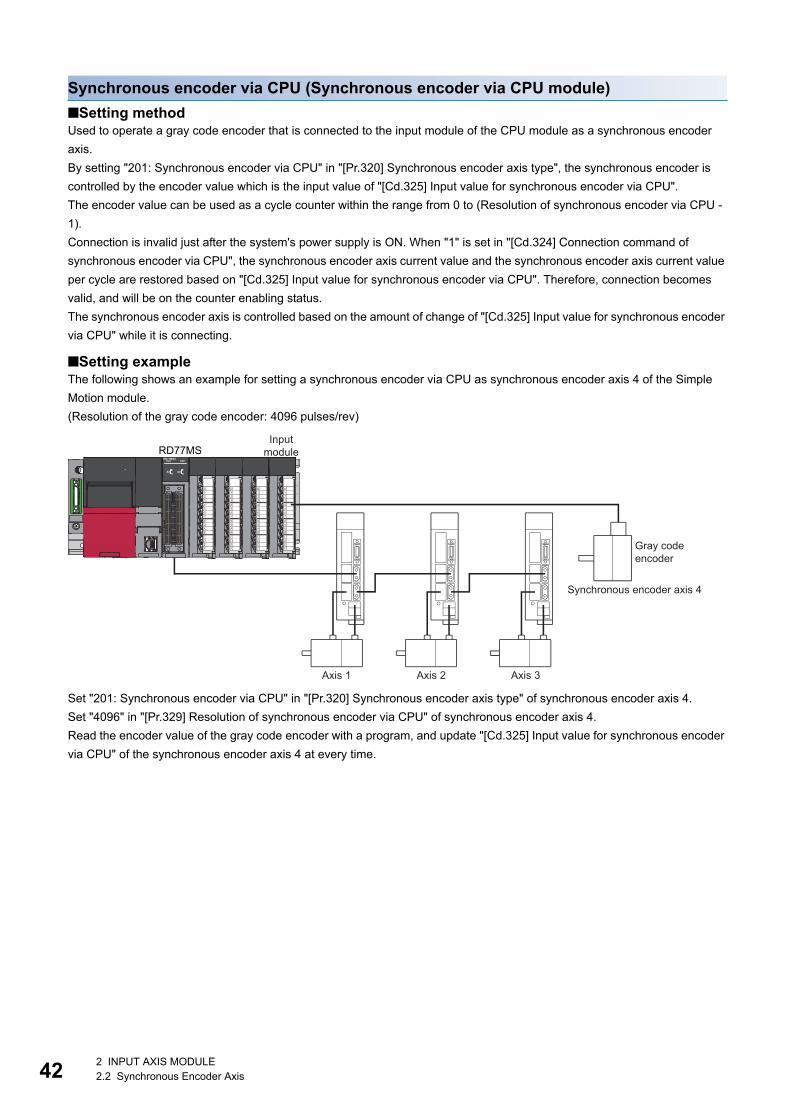
42
Synchronous encoder via CPU (Synchronous encoder via CPU module)
■Setting methodUsed to operate a gray code encoder that is connected to the input module of the CPU module as a synchronous encoder
axis.
By setting "201: Synchronous encoder via CPU" in "[Pr.320] Synchronous encoder axis type", the synchronous encoder is
controlled by the encoder value which is the input value of "[Cd.325] Input value for synchronous encoder via CPU".
The encoder value can be used as a cycle counter within the range from 0 to (Resolution of synchronous encoder via CPU -
1).
Connection is invalid just after the system's power supply is ON. When "1" is set in "[Cd.324] Connection command of
synchronous encoder via CPU", the synchronous encoder axis current value and the synchronous encoder axis current value
per cycle are restored based on "[Cd.325] Input value for synchronous encoder via CPU". Therefore, connection becomes
valid, and will be on the counter enabling status.
The synchronous encoder axis is controlled based on the amount of change of "[Cd.325] Input value for synchronous encoder
via CPU" while it is connecting.
■Setting exampleThe following shows an example for setting a synchronous encoder via CPU as synchronous encoder axis 4 of the Simple
Motion module.
(Resolution of the gray code encoder: 4096 pulses/rev)
Set "201: Synchronous encoder via CPU" in "[Pr.320] Synchronous encoder axis type" of synchronous encoder axis 4.
Set "4096" in "[Pr.329] Resolution of synchronous encoder via CPU" of synchronous encoder axis 4.
Read the encoder value of the gray code encoder with a program, and update "[Cd.325] Input value for synchronous encoder
via CPU" of the synchronous encoder axis 4 at every time.
RD77MS4ERRRUN
AX3
4 2
1AX
RD77MSInput
module
Axis 1 Axis 2 Axis 3
Gray code encoder
Synchronous encoder axis 4
2 INPUT AXIS MODULE2.2 Synchronous Encoder Axis
2
■Restrictions • "[Cd.325] Input value for synchronous encoder via CPU" is taken every operation cycle, but it is asynchronous with the
scan time of the CPU module. Therefore, speed fluctuation of the synchronous encoder axis becomes larger if the refresh
cycle of "[Cd.325] Input value for synchronous encoder via CPU" becomes long. Update "[Cd.325] Input value for
synchronous encoder via CPU" in a cycle less than the operation cycle or use smooth speed fluctuation with the smoothing
function.
• The synchronous encoder current value that is restored for the synchronous encoder connection gets restored into a
converted value from the following range based on the synchronous encoder movement amount on disconnection.
*1 If the resolution of a synchronous encoder via CPU is an odd number, round down a negative value after the decimal point, round up a positive value after decimal point.
Setting value of "[Pr.329] Resolution of synchronous encoder via CPU"
Range of restored synchronous encoder current value
1 or more -(Resolution of synchronous encoder via CPU / 2) to (Resolution of synchronous encoder via CPU / 2 - 1) [pulse]*1
0 or less -2147483648 to 2147483647 [pulse]
2 INPUT AXIS MODULE2.2 Synchronous Encoder Axis 43

44
Synchronous encoder via link device [RD77GF]
■Setting methodUsed to operate an incremental synchronous encoder that is connected to the high-speed counter module on the CC-Link IE
Field Network as a synchronous encoder axis.
By setting "301: Synchronous encoder via link device" in "[Pr.320] Synchronous encoder axis type", the link device assigned
to the synchronous encoder input axis can be used by the link device external signal assignment function.
The status is set to the counter disable just after a link is established. The synchronous encoder axis current value and the
synchronous encoder axis current value per cycle are restored based on the link device value assigned to the synchronous
encoder input axis. Therefore, connection becomes valid.
The synchronous encoder axis is controlled based on the amount of change of the link device value assigned to the
synchronous encoder input axis while it is connecting.
■Setting exampleThe following shows an example for setting a synchronous encoder via link device as synchronous encoder axis 4 of the
Simple Motion module.
• Assign the link device to the synchronous encoder input using the link device external signal assignment function.
• Set "301: Synchronous encoder via link device" in "[Pr.320] Synchronous encoder axis type" of synchronous encoder axis
4.
The following shows an example for operating CH1 of the high-speed counter module (NZ2GFCF-D62PD2) as the ring
counter to use as synchronous encoder input. For the specification and usage methods of the high-speed counter module,
refer to the following manual.
CC-Link IE Field Network High-Speed Counter Module User's Manual
Setting item Setting value
Setting details
[Pr.710] Synchronous encoder axis: Link device type 0033H Specify the remote register RWr10 (2 words) which stores the "current
value" of the counter module.[Pr.711] Synchronous encoder axis: Link device start No. 0010H
[Pr.712] Synchronous encoder axis: Link device count direction
setting
0 The encoder current value moves toward the positive direction by the
count-up pulse.
[Pr.713] Synchronous encoder axis: Ring counter maximum value 360000 Set the upper limit of the ring counter to 360000.
(Set the value to match with the setting value of RWw12 to RWw13.)
[Pr.714] Synchronous encoder axis: Ring counter minimum value 0 Set the lower limit of the ring counter to 0.
(Set the value to match with the setting value of RWw10 to RWw11.)
RD77GF4ERRRUN
AX1-4D LINKSD/RDL ERR
L ER
LINK
RD77GF
Incremental synchronous encoderSynchronous encoder axis 2
Axis 1 Axis 2 Axis 3
High-speed counter module
2 INPUT AXIS MODULE2.2 Synchronous Encoder Axis
2
■Restrictions • When using the link device, the fetch timing of the signal disperses in one link scan cycle.
• Set the movement amount per link scan so that the following formula is satisfied. If not, the actual movement amount of the
synchronous encoder and the movement amount counted by the Simple Motion module might not be matched.
Ex.
When using the high-speed counter module shown the setting example above, set the movement amount per link scan to
180000 or less.
Movement amount per link scan|(Ring counter maximum value) - (Ring counter minimum value) + 1|
2<
Movement amount per link scan|360000 - 0 + 1|
2< = 180000.5
2 INPUT AXIS MODULE2.2 Synchronous Encoder Axis 45

46
Synchronous encoder axis parametersj: Synchronous encoder axis No. - 1 (j: Axis No. - 17 for axis 17 to axis 32)
Setting item Setting details Setting value Default value
Buffer memory address
Axis 1 to axis 16
Axis 17 to axis 32
[Pr.320]
Synchronous encoder
axis type
• Set the synchronous encoder axis type
to be used.
Fetch cycle: At power supply ON
■Set in decimal.
0: Invalid
1: Incremental synchronous encoder
[RD77MS]
101 to 116: Synchronous encoder via
servo amplifier (Connectable servo
amplifier: Axis 1 to axis 16*1) [RD77MS]
101 to 132: Synchronous encoder via
servo amplifier (Connectable servo
amplifier: Axis 1 to axis 32*1) [RD77GF]
201: Synchronous encoder via CPU
301: Synchronous encoder via link device
[RD77GF]
0 34720+20j 1034720+20j
[Pr.321]
Synchronous encoder
axis unit setting
• Set the unit of the synchronous
encoder axis.
• Set the position unit within the range
from 1 to 10-9 [control unit].
• Set the speed unit within the range
from 1 to 10-9 [control unit/s or
control unit/min].
Fetch cycle: At power supply ON
■Set in hexadecimal. 0003H 34721+20j 1034721+20j
[Pr.322]
Synchronous encoder
axis unit conversion:
Numerator
• Set the numerator to convert the unit
from the encoder pulse of the
synchronous encoder axis into the
synchronous encoder axis unit.
Fetch cycle: At power supply ON
■Set in decimal.
-2147483648 to 2147483647
[Synchronous encoder axis position
units*2]
1 34722+20j
34723+20j
1034722+20j
1034723+20j
[Pr.323]
Synchronous encoder
axis unit conversion:
Denominator
• Set the denominator to convert the unit
from the encoder pulse of the
synchronous encoder axis into the
synchronous encoder axis unit.
Fetch cycle: At power supply ON
■Set in decimal.
1 to 2147483647 [pulse]
1 34724+20j
34725+20j
1034724+20j
1034725+20j
[Pr.324]
Synchronous encoder
axis length per cycle
• Set the length per cycle of the
synchronous encoder axis.
Fetch cycle: At power supply ON
■Set in decimal.
1 to 2147483647
[Synchronous encoder axis position
units*2]
4000 34726+20j
34727+20j
1034726+20j
1034727+20j
[Pr.325]
Synchronous encoder
axis smoothing time
constant
• Set the time to smooth for the input
value.
Fetch cycle: At power supply ON
■Set in decimal.
0 to 5000 [ms]
0 34728+20j 1034728+20j
[Pr.326]
Synchronous encoder
axis phase
compensation
advance time
• Set the time to advance or delay the
phase.
Fetch cycle: Operation cycle
■Set in decimal.
-2147483648 to 2147483647 [s]
0 34730+20j
34731+20j
1034730+20j
1034731+20j
[Pr.327]
Synchronous encoder
axis phase
compensation time
constant
• Set the time constant to affect the
phase compensation.
Fetch cycle: At power supply ON
■Set in decimal.
0 to 65535 [ms]*310 34732+20j 1034732+20j
[Pr.328]
Synchronous encoder
axis rotation direction
restriction
• Set this parameter to restrict the input
movement amount to one direction.
Fetch cycle: At power supply ON
■Set in decimal.
0: Without rotation direction restriction
1: Enable only for current value increase
direction
2: Enable only for current value decrease
direction
0 34733+20j 1034733+20j
H _ _ _ _Control unit
0: mm, 1: inch,2: degree, 3: pulse
Number of decimal placesfor position
0 to 9Speed time unit
0: second [s],1: minute [min]
Number of decimal placesfor speed
0 to 9
2 INPUT AXIS MODULE2.2 Synchronous Encoder Axis

2
*1 The range from axis 1 to 2 is valid in the 2-axis module, from axis 1 to 4 is valid in the 4-axis module, from axis 1 to 8 is valid in the 8-axis module, from axis 1 to 16 is valid in the 16-axis module, and from axis 1 to 32 is valid in the 32-axis module.
*2 Synchronous encoder axis position units (Page 36 Synchronous encoder axis position units)*3 Set the value as follows in a program.
0 to 32767: Set as a decimal32768 to 65535: Convert into a hexadecimal and set
[Pr.320] Synchronous encoder axis typeSet the synchronous encoder type to be generated of the input value for the synchronous encoder axis.
*1 The range from axis 1 to 2 is valid in the 2-axis module, from axis 1 to 4 is valid in the 4-axis module, from axis 1 to 8 is valid in the 8-axis module, from axis 1 to 16 is valid in the 16-axis module, and from axis 1 to 32 is valid in the 32-axis module.
[Pr.321] Synchronous encoder axis unit settingSet the position and speed unit of the synchronous encoder axis. Refer to the following for details.
Page 36 Units for the synchronous encoder axis
[Pr.322] Synchronous encoder axis unit conversion: NumeratorThe input movement amount of synchronous encoder is configured in encoder pulse units.
The units can be arbitrarily converted through unit conversation with setting [Pr.322] and [Pr.323].
Set [Pr.322] and [Pr.323] according to the controlled machine.
The movement amount corresponding to "[Pr.323] Synchronous encoder axis unit conversion: Denominator" is set in "[Pr.322]
Synchronous encoder axis unit conversion: Numerator" in synchronous encoder axis position units (Page 36
Synchronous encoder axis position units).
The input movement amount can be reversed by the setting negative values. Set "[Pr.323] Synchronous encoder axis unit
conversion: Denominator" based on encoder pulse units from the synchronous encoder. Set a value within the range from 1 to
2147483647
[Pr.329]
Resolution of
synchronous encoder
via CPU
• Set the resolution of the synchronous
encoder when the synchronous
encoder axis type is set to
synchronous encoder via CPU.
• If 0 or less is set, the input value of
synchronous encoder via CPU is
processed as 32-bit counter.
Fetch cycle: At power supply ON
■Set in decimal.
-2147483648 to 2147483647 [pulse]
0 34734+20j
34735+20j
1034734+20j
1034735+20j
Setting value Details
0: Invalid Synchronous encoder axis is invalid.
1: Incremental synchronous encoder [RD77MS] Generate the input value based on the incremental synchronous encoder input.
101 to 132: Synchronous encoder via servo
amplifier
(Connectable servo amplifier: Axis 1 to axis 32*1)
Generate the input value based on the synchronous encoder input via servo amplifier connected to the
specified servo amplifier (axis 1 to axis 32).
201: Synchronous encoder via CPU Generate the input value with the value set in the buffer memory by the CPU module as the encoder value.
301: Synchronous encoder via link device
[RD77GF]
Use an arbitrary value of link device as synchronous encoder input.
Setting item Setting details Setting value Default value
Buffer memory address
Axis 1 to axis 16
Axis 17 to axis 32
= ×"[Pr.322] Synchronous encoder axis unit conversion: Numerator"
"[Pr.323] Synchronous encoder axis unit conversion: Denominator"
Synchronous encoder axis movement amount (Movement amount after unit conversion)
Synchronous encoder input movement amount
(Encoder pulse units)
2 INPUT AXIS MODULE2.2 Synchronous Encoder Axis 47
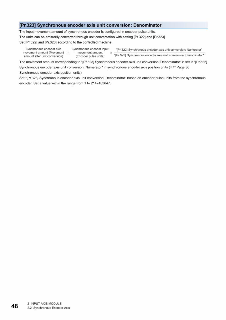
48
[Pr.323] Synchronous encoder axis unit conversion: DenominatorThe input movement amount of synchronous encoder is configured in encoder pulse units.
The units can be arbitrarily converted through unit conversation with setting [Pr.322] and [Pr.323].
Set [Pr.322] and [Pr.323] according to the controlled machine.
The movement amount corresponding to "[Pr.323] Synchronous encoder axis unit conversion: Denominator" is set in "[Pr.322]
Synchronous encoder axis unit conversion: Numerator" in synchronous encoder axis position units (Page 36
Synchronous encoder axis position units).
Set "[Pr.323] Synchronous encoder axis unit conversion: Denominator" based on encoder pulse units from the synchronous
encoder. Set a value within the range from 1 to 2147483647.
= ×"[Pr.322] Synchronous encoder axis unit conversion: Numerator"
"[Pr.323] Synchronous encoder axis unit conversion: Denominator"
Synchronous encoder axis movement amount (Movement amount after unit conversion)
Synchronous encoder input movement amount
(Encoder pulse units)
2 INPUT AXIS MODULE2.2 Synchronous Encoder Axis

2
[Pr.324] Synchronous encoder axis length per cycleSet the length per cycle for the synchronous encoder axis current value per cycle.
The current value of synchronous encoder axis is stored in "[Md.321] Synchronous encoder axis current value per cycle" at
ring counter based on the setting value.
The unit settings are in synchronous encoder axis position units (Page 36 Synchronous encoder axis position units). Set
a value within the range from 1 to 2147483647.
Set a value within the range from 1 to 2147483647.
■Setting example of the unit conversion and the length per cycle.The following shows an example a rotary encoder is connected which resolution is 4000 [pulse/rev] to the motor axis side on
the rotation table that drives by 1/5 pulley system, and the control unit is degree.
• Position unit: 0.1 [degree]
• Speed unit: 0.001 [degree/min]
• Length per cycle: 360.0 [degree] (1 cycle of the rotation table)
Setting item Setting details Setting value
[Pr.321]
Synchronous encoder axis unit
setting
Control unit 2: degree 3112H
Number of decimal places for position 1
Speed time unit 1: minute [min]
Number of decimal places for speed 3
[Pr.322] Synchronous encoder axis unit conversion: Numerator 360.0 [degree] 1 3600 [ 0.1 degree]
[Pr.323] Synchronous encoder axis unit conversion: Denominator 4000 [pulse] 5 20000 [pulse]
[Pr.324] Synchronous encoder axis length per cycle 360.0 [degree] 3600 [ 0.1 degree]
t
[pulse]
20000
40000
t
[ × 0.1 degree]
72003600
t3600
[ × 0.1 degree]
t
[ × 0.001 degree/min]
Synchronous encoderinput pulse
[Pr.322], [Pr.323]Synchronous encoder axis unit conversion
[Md.322] Synchronous encoder axis speed (Speed after unit conversion)
[Md.321] Synchronous encoder axis current value per cycle
[Md.320] Synchronous encoder axis current value
[Pr.324] Synchronous encoder axis length per cycle
2 INPUT AXIS MODULE2.2 Synchronous Encoder Axis 49
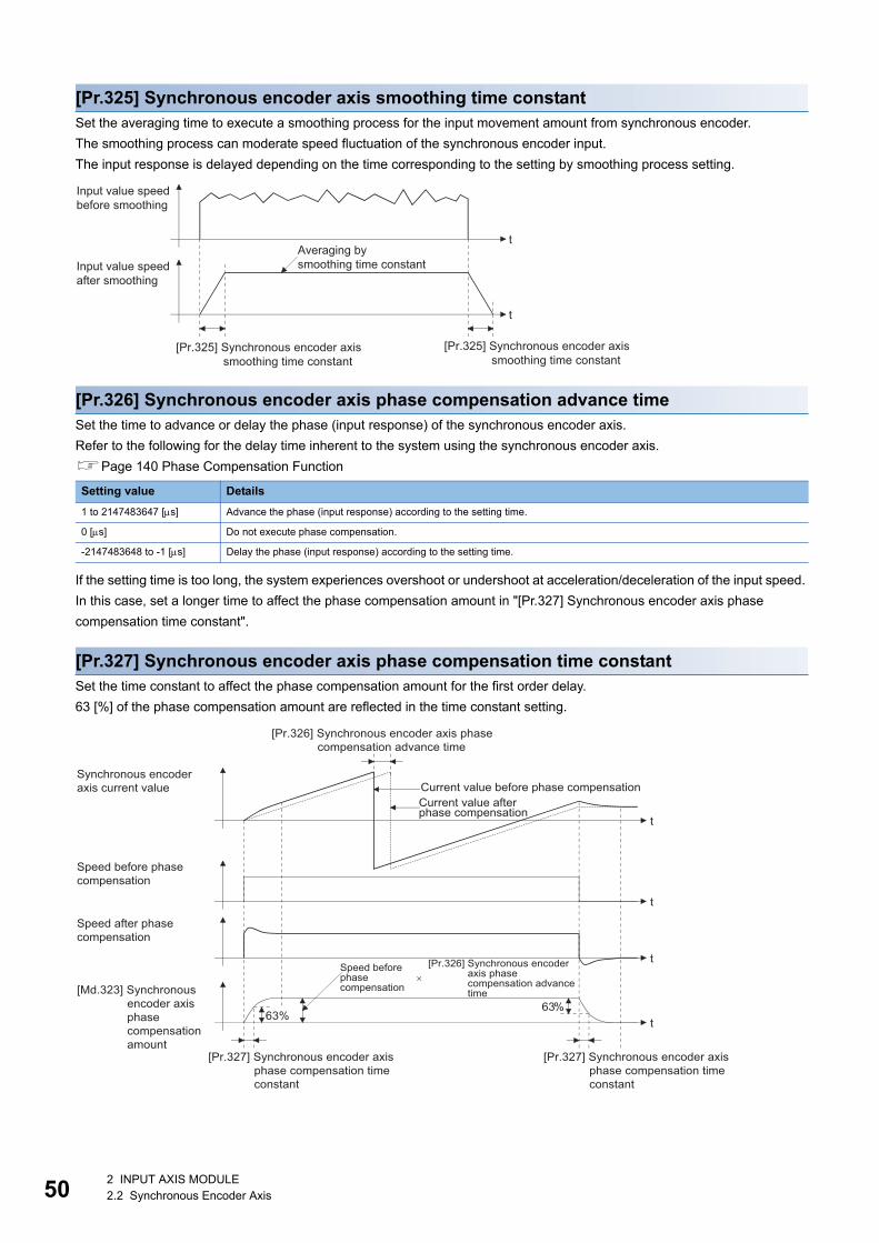
50
[Pr.325] Synchronous encoder axis smoothing time constantSet the averaging time to execute a smoothing process for the input movement amount from synchronous encoder.
The smoothing process can moderate speed fluctuation of the synchronous encoder input.
The input response is delayed depending on the time corresponding to the setting by smoothing process setting.
[Pr.326] Synchronous encoder axis phase compensation advance timeSet the time to advance or delay the phase (input response) of the synchronous encoder axis.
Refer to the following for the delay time inherent to the system using the synchronous encoder axis.
Page 140 Phase Compensation Function
If the setting time is too long, the system experiences overshoot or undershoot at acceleration/deceleration of the input speed.
In this case, set a longer time to affect the phase compensation amount in "[Pr.327] Synchronous encoder axis phase
compensation time constant".
[Pr.327] Synchronous encoder axis phase compensation time constantSet the time constant to affect the phase compensation amount for the first order delay.
63 [%] of the phase compensation amount are reflected in the time constant setting.
Setting value Details
1 to 2147483647 [s] Advance the phase (input response) according to the setting time.
0 [s] Do not execute phase compensation.
-2147483648 to -1 [s] Delay the phase (input response) according to the setting time.
t
t
Input value speedbefore smoothing
Input value speedafter smoothing
Averaging bysmoothing time constant
[Pr.325] Synchronous encoder axis smoothing time constant
[Pr.325] Synchronous encoder axis smoothing time constant
t
t
t
t63%63%
Current value before phase compensationSynchronous encoder axis current value
Speed before phase compensation
Speed after phase compensation
[Md.323] Synchronous encoder axis phase compensation amount
[Pr.326] Synchronous encoder axis phase compensation advance time
Current value after phase compensation
[Pr.327] Synchronous encoder axis phase compensation time constant
[Pr.327] Synchronous encoder axis phase compensation time constant
[Pr.326] Synchronous encoder axis phase compensation advance time
Speed before phase compensation
×
2 INPUT AXIS MODULE2.2 Synchronous Encoder Axis
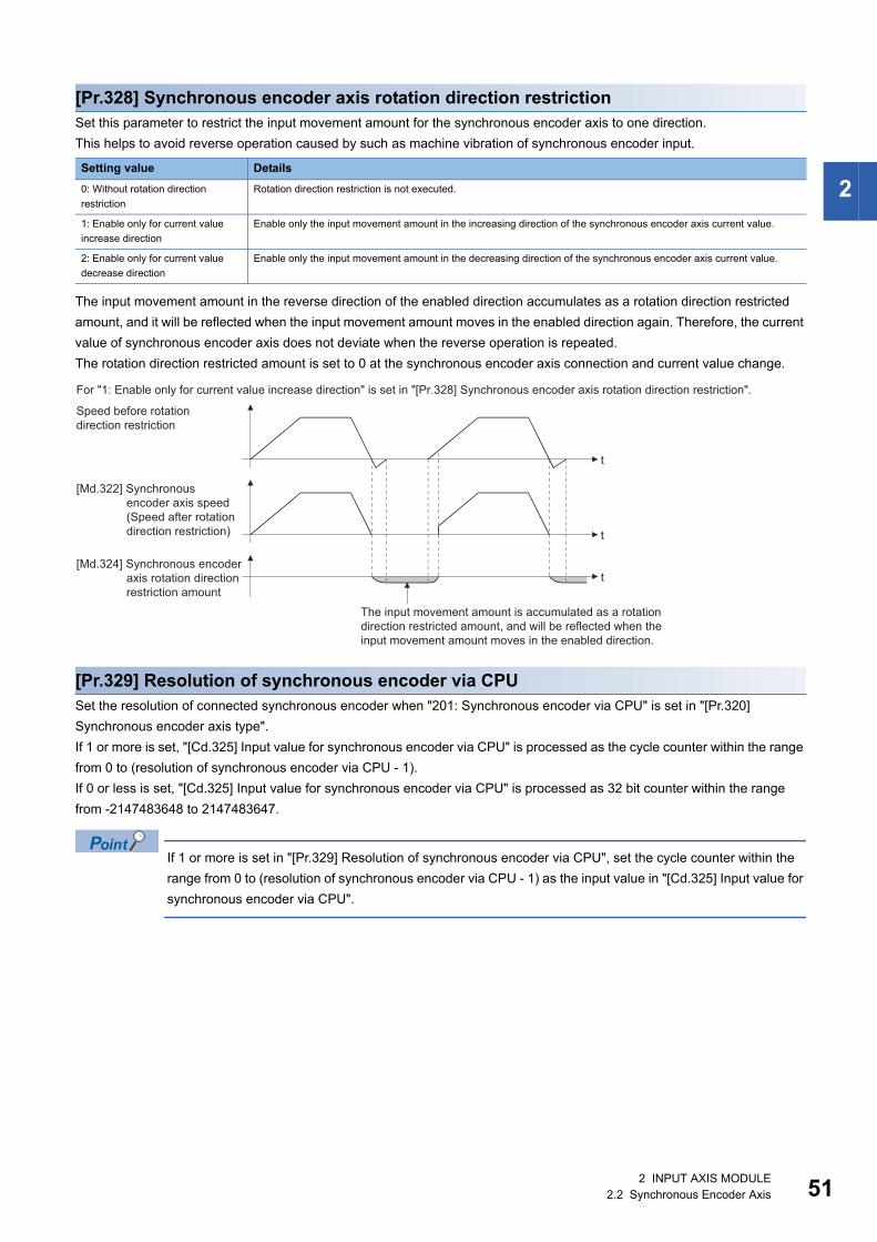
2
[Pr.328] Synchronous encoder axis rotation direction restrictionSet this parameter to restrict the input movement amount for the synchronous encoder axis to one direction.
This helps to avoid reverse operation caused by such as machine vibration of synchronous encoder input.
The input movement amount in the reverse direction of the enabled direction accumulates as a rotation direction restricted
amount, and it will be reflected when the input movement amount moves in the enabled direction again. Therefore, the current
value of synchronous encoder axis does not deviate when the reverse operation is repeated.
The rotation direction restricted amount is set to 0 at the synchronous encoder axis connection and current value change.
[Pr.329] Resolution of synchronous encoder via CPUSet the resolution of connected synchronous encoder when "201: Synchronous encoder via CPU" is set in "[Pr.320]
Synchronous encoder axis type".
If 1 or more is set, "[Cd.325] Input value for synchronous encoder via CPU" is processed as the cycle counter within the range
from 0 to (resolution of synchronous encoder via CPU - 1).
If 0 or less is set, "[Cd.325] Input value for synchronous encoder via CPU" is processed as 32 bit counter within the range
from -2147483648 to 2147483647.
If 1 or more is set in "[Pr.329] Resolution of synchronous encoder via CPU", set the cycle counter within the
range from 0 to (resolution of synchronous encoder via CPU - 1) as the input value in "[Cd.325] Input value for
synchronous encoder via CPU".
Setting value Details
0: Without rotation direction
restriction
Rotation direction restriction is not executed.
1: Enable only for current value
increase direction
Enable only the input movement amount in the increasing direction of the synchronous encoder axis current value.
2: Enable only for current value
decrease direction
Enable only the input movement amount in the decreasing direction of the synchronous encoder axis current value.
t
t
t
Speed before rotation direction restriction
[Md.322] Synchronous encoder axis speed (Speed after rotation direction restriction)
[Md.324] Synchronous encoder axis rotation direction restriction amount
The input movement amount is accumulated as a rotation direction restricted amount, and will be reflected when the input movement amount moves in the enabled direction.
For "1: Enable only for current value increase direction" is set in "[Pr.328] Synchronous encoder axis rotation direction restriction".
2 INPUT AXIS MODULE2.2 Synchronous Encoder Axis 51

52
Synchronous encoder axis parameters via link device [RD77GF]j: Synchronous encoder axis No. - 1 (j: Axis No. - 17 for axis 17 to axis 32)
Setting item Setting details Setting value Default value
Buffer memory address
Axis 1 to axis 16
Axis 17 to axis 32
[Pr.710]
Synchronous encoder
axis: Link device type
Set link device type for use.
Fetch cycle: At power supply ON
Set in hexadecimal.
Other than below: Invalid
21H: RX (1 word)
22H: RY (1 word)
23H: RWr (1 word)
24H: RWw (1 word)
31H: RX (2 words)
32H: RY (2 words)
33H: RWr (2 words)
34H: RWw (2 words)
0000H 35520+20j 1035520+20j
[Pr.711]
Synchronous encoder
axis: Link device start
No.
Set link device No. for use.
Fetch cycle: At power supply ON
Set in hexadecimal.
0 to 1FFFH
0000H 35521+20j 1035521+20j
[Pr.712]
Synchronous encoder
axis: Link device
count direction setting
Set the relationship between link device
count direction and assignment signal
count direction.
(Valid for only 0th bit)
Fetch cycle: At power supply ON
Set in decimal.
0: Plus count (The signal will also be plus
counted while the link device is plus
count.)
1: Minus count (The signal will be minus
counted while the link device is plus
count.)
0 35526+20j 1035526+20j
[Pr.713]
Synchronous encoder
axis: Ring counter
maximum value
Set the relationship between link device
count direction and assignment signal
count direction.
• When the ring counter maximum value
is equal to the ring counter minimum
value, the setting depends on the link
device type setting.
• When the link device type is a 1-word
device and a value outside the range of
1 word is set, the setting is ignored.(-
32768 to 32767)
• When the ring counter maximum value
is smaller than the ring counter
minimum value, the error "Outside the
link device maximum/minimum value
specification range" (error code:
1CC2H) occurs.
Fetch cycle: At power supply ON
Set in decimal.
1 word: -32768 to 32767
2 words: -2147483648 to 2147483647
0 35522+20j
35523+20j
1035522+20j
1035523+20j
[Pr.714]
Synchronous encoder
axis: Ring counter
minimum value
35524+20j
35525+20j
1035524+20j
1035525+20j
[Pr.1010]
Synchronous encoder
axis start request:
Link device type
Set link device type for use.
Fetch cycle: At power supply ON
Set in hexadecimal.
Other than below: Invalid
11H: RX (1 bit)
12H: RY (1 bit)
13H: RWr (1 bit)
14H: RWw (1 bit)
0000H 35530+20j 1035530+20j
[Pr.1011]
Synchronous encoder
axis start request:
Link device start No.
Set link device No. for use.
Fetch cycle: At power supply ON
Set in hexadecimal.
0 to 1FFFH
0000H 35531+20j 1035531+20j
[Pr.1012]
Synchronous encoder
axis start request:
Link device bit
specification
Set the bit No. that used in occasion
when "13H: RWr (1 bit)" and "14H: RWw
(1 bit)" had been set to "[Pr.1010] Link
device type".
Fetch cycle: At power supply ON
Set in hexadecimal.
00H to 0FH
0000H 35532+20j 1035532+20j
[Pr.1013]
Synchronous encoder
axis start request:
Link device logic
setting
Set the logic for assignment signal.
(Valid for only 0th bit)
Fetch cycle: At power supply ON
Set in decimal.
0: Negative logic
1: Positive logic
0 35533+20j 1035533+20j
2 INPUT AXIS MODULE2.2 Synchronous Encoder Axis
2
• Set [Pr.710] to [Pr.714] when an arbitrary value of link device is used as synchronous encoder input.
• Set [Pr.1010] to [Pr.1013] when an arbitrary value of link device is used as synchronous encoder axis start request.
[Pr.710] Synchronous encoder axis: Link device typeSet link device type for use.
Other than below: Invalid
21H: RX (1 word)
22H: RY (1 word)
23H: RWr (1 word)
24H: RWw (1 word)
31H: RX (2 words)
32H: RY (2 words)
33H: RWr (2 words)
34H: RWw (2 words)
[Pr.711] Synchronous encoder axis: Link device start No.Set link device No. for use.
If the link device No. out of the range is set, the error "Outside link device start No. range" (error code: 1CC0H) occurs and the
synchronous encoder input via link device cannot be used.
[Pr.712] Synchronous encoder axis: Link device count direction settingSet the relationship between link device count direction and assignment signal count direction.
(Valid for only 0th bit)
0: Plus count (The signal will also be plus counted while the link device is plus count.)
1: Minus count (The signal will be minus counted while the link device is plus count.)
[Pr.713] Synchronous encoder axis: Ring counter maximum valueSet the maximum value when the link device value is ring counter.
[When the link device type is set to 1 word]
The maximum value: 32767
[When the link device type is set to 2 words]
The maximum value: 2147483647
• When the ring counter maximum value is equal to the ring counter minimum value, the setting depends on the link device
type setting.
• When the link device type is a 1-word device and a value outside the range of 1 word is set, the setting is ignored.
• When the ring counter maximum value is smaller than the ring counter minimum value, the error "Outside the link device
maximum/minimum value specification range" (error code: 1CC2H) occurs.
[Pr.714] Synchronous encoder axis: Ring counter minimum valueSet the minimum value when the link device value is ring counter.
[When the link device type is set to 1 word]
The minimum value: -32768
[When the link device type is set to 2 words]
The minimum value: -2147483648
• When the ring counter maximum value is equal to the ring counter minimum value, the setting depends on the link device
type setting.
• When the link device type is a 1-word device and a value outside the range of 1 word is set, the setting is ignored.
• When the ring counter maximum value is smaller than the ring counter minimum value, the error "Outside the link device
maximum/minimum value specification range" (error code: 1CC2H) occurs.
2 INPUT AXIS MODULE2.2 Synchronous Encoder Axis 53

54
[Pr.1010] Synchronous encoder axis start request: Link device typeSet link device type for use.
Other than below: Invalid
11H: RX (1 bit)
12H: RY (1 bit)
13H: RWr (1 bit)
14H: RWw (1 bit)
[Pr.1011] Synchronous encoder axis start request: Link device start No.Set link device No. for use.
If the link device No. out of the range is set, the error "Outside link device start No. range" (error code: 1CC0H) occurs and the
synchronous encoder axis start via link device cannot be used.
[Pr.1012] Synchronous encoder axis start request: Link device bit specificationSet the bit No. that used in occasion when "13H: RWr (1 bit)" and "14H: RWw (1 bit)" had been set to "[Pr.1010] Link device
type".
Setting range: 00H to 0FH
If the value out of the range is set, the error "Outside the link device bit specification range" (error code: 1CC1H) occurs and
the synchronous encoder axis start via link device cannot be used.
[Pr.1013] Synchronous encoder axis start request: Link device logic settingSet the logic for assignment signal.
(Valid for only 0th bit)
0: Negative logic
1: Positive logic
2 INPUT AXIS MODULE2.2 Synchronous Encoder Axis

2
Synchronous encoder axis control dataj: Synchronous encoder axis No. - 1 (j: Axis No. - 17 for axis 17 to axis 32)
*1 With the exception of positioning control, main cycle processing is executed during the next available time. It changes by status of axis start.
*2 The range from axis 1 to 2 is valid in the 2-axis module, from axis 1 to 4 is valid in the 4-axis module, from axis 1 to 8 is valid in the 8-axis module, and from axis 1 to 16 is valid in the 16-axis module.
*3 Synchronous encoder axis position units (Page 36 Synchronous encoder axis position units)
Setting item Setting details Setting value Default value
Buffer memory address
Axis 1 to axis 16
Axis 17 to axis 32
[Cd.320]
Synchronous encoder
axis control start
• If set to "1", the synchronous encoder axis
control is started.
• If set to "101 to 116", the synchronous encoder
axis control starts based on the highspeed input
request (external command signal). [RD77MS]
• If set to "201", the synchronous encoder axis
control starts based on the synchronous
encoder axis control request. [RD77GF]
• The Simple Motion module resets the value to
"0" automatically after completion of the
synchronous encoder axis control.
Fetch cycle: Operation cycle
■Set in decimal.
1: Start for synchronous encoder
axis control
101 to 116: High-speed input
start for synchronous encoder
axis control (axis 1 to axis 16*2)
[RD77MS]
201: Start request for
synchronous encoder axis
control (link device) [RD77GF]
0 35040+10j 1035040+10j
[Cd.321]
Synchronous encoder
axis control method
• Set the control method for the synchronous
encoder axis
Fetch cycle: At synchronous encoder axis control
start
■Set in decimal.
0: Current value change
1: Counter disable
2: Counter enable
0 35041+10j 1035041+10j
[Cd.322]
Synchronous encoder
axis current value
setting address
• Set a new current value for changing the
current value.
Fetch cycle: At synchronous encoder axis control
start
■Set in decimal.
-2147483648 to 2147483647
[Synchronous encoder axis
position units*3]
0 35042+10j
35043+10j
1035042+10j
1035043+10j
[Cd.323]
Synchronous encoder
axis error reset
• If set to "1" for resetting error and warning for
the synchronous encoder axis, the error No.
and warning No. are set to 0, and the error
detection and warning detection bits status are
turned OFF.
• The Simple Motion module resets the value to
"0" automatically after completion of the error
reset.
• In the case of the synchronous encoder axis
parameter error, even if the error is reset, the
setting valid flag of the synchronous encoder
axis status has been OFF.
Fetch cycle: Main cycle*1
■Set in decimal.
1: Error reset request
0 35044+10j 1035044+10j
[Cd.324]
Connection command
of synchronous
encoder via CPU
• If set to "1", the synchronous encoder via CPU
is connected.
• If set to "0", the synchronous encoder via CPU
is disconnected.
Fetch cycle: Main cycle*1
■Set in decimal.
1: Connect synchronous encoder
via CPU
0: Disconnect synchronous
encoder via CPU
0 35045+10j 1035045+10j
[Cd.325]
Input value for
synchronous encoder
via CPU
• Set a value to be used every time as the input
value for the synchronous encoder for the
synchronous encoder via CPU.
Fetch cycle: Operation cycle
■Set in decimal.
-2147483648 to 2147483647
[pulse]
0 35046+10j
35047+10j
1035046+10j
1035047+10j
2 INPUT AXIS MODULE2.2 Synchronous Encoder Axis 55
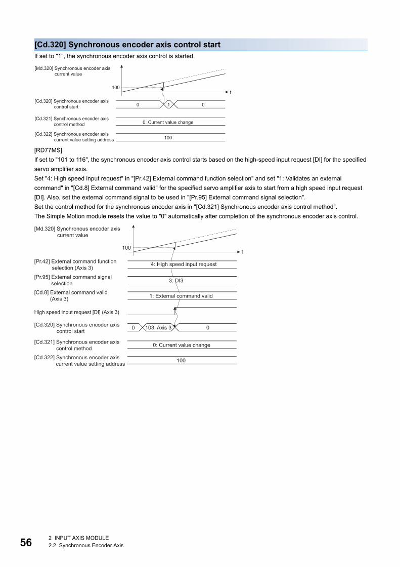
56
[Cd.320] Synchronous encoder axis control startIf set to "1", the synchronous encoder axis control is started.
[RD77MS]
If set to "101 to 116", the synchronous encoder axis control starts based on the high-speed input request [DI] for the specified
servo amplifier axis.
Set "4: High speed input request" in "[Pr.42] External command function selection" and set "1: Validates an external
command" in "[Cd.8] External command valid" for the specified servo amplifier axis to start from a high speed input request
[DI]. Also, set the external command signal to be used in "[Pr.95] External command signal selection".
Set the control method for the synchronous encoder axis in "[Cd.321] Synchronous encoder axis control method".
The Simple Motion module resets the value to "0" automatically after completion of the synchronous encoder axis control.
t
010
100
100
0: Current value change
[Md.320] Synchronous encoder axis current value
[Cd.320] Synchronous encoder axis control start
[Cd.321] Synchronous encoder axis control method
[Cd.322] Synchronous encoder axis current value setting address
4: High speed input request
0: Current value change
103: Axis 3
100
1: External command valid
High speed input request [DI] (Axis 3)
t100
0 0
3: DI3
[Md.320] Synchronous encoder axis current value
[Pr.42] External command function selection (Axis 3)
[Cd.8] External command valid (Axis 3)
[Cd.320] Synchronous encoder axis control start
[Cd.321] Synchronous encoder axis control method
[Cd.322] Synchronous encoder axis current value setting address
[Pr.95] External command signal selection
2 INPUT AXIS MODULE2.2 Synchronous Encoder Axis
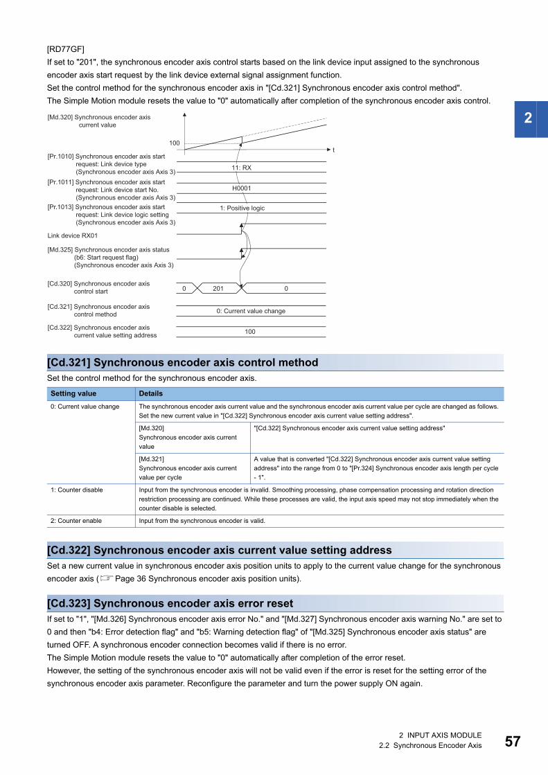
2
[RD77GF]
If set to "201", the synchronous encoder axis control starts based on the link device input assigned to the synchronous
encoder axis start request by the link device external signal assignment function.
Set the control method for the synchronous encoder axis in "[Cd.321] Synchronous encoder axis control method".
The Simple Motion module resets the value to "0" automatically after completion of the synchronous encoder axis control.
[Cd.321] Synchronous encoder axis control methodSet the control method for the synchronous encoder axis.
[Cd.322] Synchronous encoder axis current value setting addressSet a new current value in synchronous encoder axis position units to apply to the current value change for the synchronous
encoder axis (Page 36 Synchronous encoder axis position units).
[Cd.323] Synchronous encoder axis error resetIf set to "1", "[Md.326] Synchronous encoder axis error No." and "[Md.327] Synchronous encoder axis warning No." are set to
0 and then "b4: Error detection flag" and "b5: Warning detection flag" of "[Md.325] Synchronous encoder axis status" are
turned OFF. A synchronous encoder connection becomes valid if there is no error.
The Simple Motion module resets the value to "0" automatically after completion of the error reset.
However, the setting of the synchronous encoder axis will not be valid even if the error is reset for the setting error of the
synchronous encoder axis parameter. Reconfigure the parameter and turn the power supply ON again.
Setting value Details
0: Current value change The synchronous encoder axis current value and the synchronous encoder axis current value per cycle are changed as follows.
Set the new current value in "[Cd.322] Synchronous encoder axis current value setting address".
[Md.320]
Synchronous encoder axis current
value
"[Cd.322] Synchronous encoder axis current value setting address"
[Md.321]
Synchronous encoder axis current
value per cycle
A value that is converted "[Cd.322] Synchronous encoder axis current value setting
address" into the range from 0 to "[Pr.324] Synchronous encoder axis length per cycle
- 1".
1: Counter disable Input from the synchronous encoder is invalid. Smoothing processing, phase compensation processing and rotation direction
restriction processing are continued. While these processes are valid, the input axis speed may not stop immediately when the
counter disable is selected.
2: Counter enable Input from the synchronous encoder is valid.
[Cd.321] Synchronous encoder axis control method
[Cd.320] Synchronous encoder axis control start
[Md.320] Synchronous encoder axis current value
[Pr.1010] Synchronous encoder axis start request: Link device type
(Synchronous encoder axis Axis 3)
Link device RX01
[Pr.1013] Synchronous encoder axis start request: Link device logic setting (Synchronous encoder axis Axis 3)
[Pr.1011] Synchronous encoder axis start request: Link device start No.
(Synchronous encoder axis Axis 3)
[Md.325] Synchronous encoder axis status (b6: Start request flag) (Synchronous encoder axis Axis 3)
t100
100
02010
11: RX
H0001
0: Current value change
1: Positive logic
[Cd.322] Synchronous encoder axis current value setting address
2 INPUT AXIS MODULE2.2 Synchronous Encoder Axis 57

58
[Cd.324] Connection command of synchronous encoder via CPUUse this data when "201: Synchronous encoder via CPU" is set in "[Pr.320] Synchronous encoder axis type".
If set to"1", the synchronous encoder axis is connected. Once connected, the synchronous encoder current value is restored
based on the "[Cd.325] Input value for synchronous encoder via CPU".
If set to "0", the synchronous encoder axis is disconnected.
[Cd.325] Input value for synchronous encoder via CPUUse this data when "201: Synchronous encoder via CPU" is set in "[Pr.320] Synchronous encoder axis type".
Set a value to be used every time as the input value for the synchronous encoder in encoder pulse units.
If 1 or more is set in "[Pr.329] Resolution of synchronous encoder via CPU", it is processed as a cycle counter within the range
from 0 to (resolution of synchronous encoder via CPU - 1).
2 INPUT AXIS MODULE2.2 Synchronous Encoder Axis
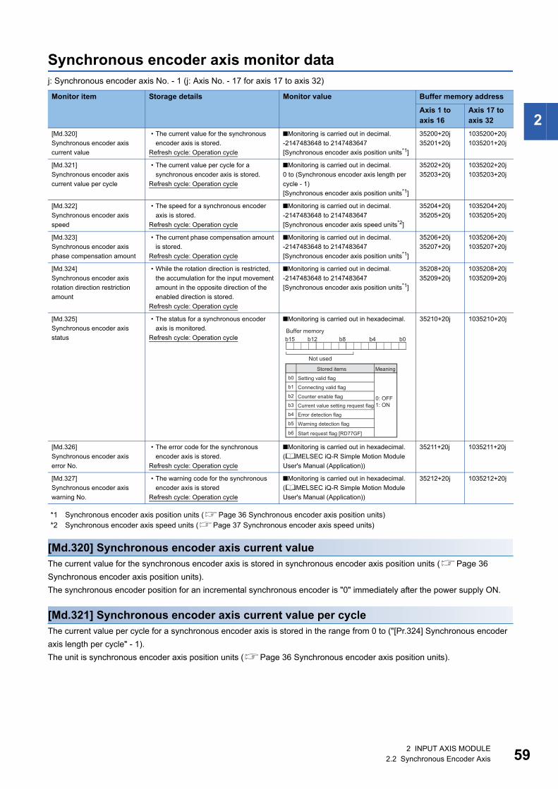
2
Synchronous encoder axis monitor dataj: Synchronous encoder axis No. - 1 (j: Axis No. - 17 for axis 17 to axis 32)
*1 Synchronous encoder axis position units (Page 36 Synchronous encoder axis position units)*2 Synchronous encoder axis speed units (Page 37 Synchronous encoder axis speed units)
[Md.320] Synchronous encoder axis current valueThe current value for the synchronous encoder axis is stored in synchronous encoder axis position units (Page 36
Synchronous encoder axis position units).
The synchronous encoder position for an incremental synchronous encoder is "0" immediately after the power supply ON.
[Md.321] Synchronous encoder axis current value per cycleThe current value per cycle for a synchronous encoder axis is stored in the range from 0 to ("[Pr.324] Synchronous encoder
axis length per cycle" - 1).
The unit is synchronous encoder axis position units (Page 36 Synchronous encoder axis position units).
Monitor item Storage details Monitor value Buffer memory address
Axis 1 to axis 16
Axis 17 to axis 32
[Md.320]
Synchronous encoder axis
current value
• The current value for the synchronous
encoder axis is stored.
Refresh cycle: Operation cycle
■Monitoring is carried out in decimal.
-2147483648 to 2147483647
[Synchronous encoder axis position units*1]
35200+20j
35201+20j
1035200+20j
1035201+20j
[Md.321]
Synchronous encoder axis
current value per cycle
• The current value per cycle for a
synchronous encoder axis is stored.
Refresh cycle: Operation cycle
■Monitoring is carried out in decimal.
0 to (Synchronous encoder axis length per
cycle - 1)
[Synchronous encoder axis position units*1]
35202+20j
35203+20j
1035202+20j
1035203+20j
[Md.322]
Synchronous encoder axis
speed
• The speed for a synchronous encoder
axis is stored.
Refresh cycle: Operation cycle
■Monitoring is carried out in decimal.
-2147483648 to 2147483647
[Synchronous encoder axis speed units*2]
35204+20j
35205+20j
1035204+20j
1035205+20j
[Md.323]
Synchronous encoder axis
phase compensation amount
• The current phase compensation amount
is stored.
Refresh cycle: Operation cycle
■Monitoring is carried out in decimal.
-2147483648 to 2147483647
[Synchronous encoder axis position units*1]
35206+20j
35207+20j
1035206+20j
1035207+20j
[Md.324]
Synchronous encoder axis
rotation direction restriction
amount
• While the rotation direction is restricted,
the accumulation for the input movement
amount in the opposite direction of the
enabled direction is stored.
Refresh cycle: Operation cycle
■Monitoring is carried out in decimal.
-2147483648 to 2147483647
[Synchronous encoder axis position units*1]
35208+20j
35209+20j
1035208+20j
1035209+20j
[Md.325]
Synchronous encoder axis
status
• The status for a synchronous encoder
axis is monitored.
Refresh cycle: Operation cycle
■Monitoring is carried out in hexadecimal. 35210+20j 1035210+20j
[Md.326]
Synchronous encoder axis
error No.
• The error code for the synchronous
encoder axis is stored.
Refresh cycle: Operation cycle
■Monitoring is carried out in hexadecimal.
(MELSEC iQ-R Simple Motion Module
User's Manual (Application))
35211+20j 1035211+20j
[Md.327]
Synchronous encoder axis
warning No.
• The warning code for the synchronous
encoder axis is stored
Refresh cycle: Operation cycle
■Monitoring is carried out in hexadecimal.
(MELSEC iQ-R Simple Motion Module
User's Manual (Application))
35212+20j 1035212+20j
0: OFF1: ON
b0
b1
b2
b3
b4
b5
b6
b15 b0b4b8b12
Not used
Buffer memory
Stored items Meaning
Setting valid flag
Connecting valid flag
Counter enable flag
Current value setting request flag
Error detection flag
Warning detection flag
Start request flag [RD77GF]
2 INPUT AXIS MODULE2.2 Synchronous Encoder Axis 59

60
[Md.322] Synchronous encoder axis speedThe speed for a synchronous encoder axis is stored in synchronous encoder axis speed units (Page 37 Synchronous
encoder axis speed units).
If the speed for a synchronous encoder axis exceeds the monitor range (Page 35 Overview of synchronous encoder
axis), the warning "Input axis speed display over" (warning code: 0BD2H) will occur. In this case, use a smaller number of
decimal places for the speed in "[Pr.321] Synchronous encoder axis unit setting" or set the speed time units to "0: second [s]".
[Md.323] Synchronous encoder axis phase compensation amountThe phase compensation amount for a synchronous encoder axis is stored in the synchronous encoder axis position units
(Page 36 Synchronous encoder axis position units).
The phase compensation amount for a synchronous encoder axis is the value after smoothing processing and phase
compensation processing.
[Md.324] Synchronous encoder axis rotation direction restriction amountWhile the rotation direction is restricted for a synchronous encoder axis, the accumulation for input movement amount in the
opposite direction of the enabled direction is stored in synchronous encoder axis position units (Page 36 Synchronous
encoder axis position units) as follows.
Rotation direction restriction is processed after phase compensation processing. Therefore, if undershoot occurs from phase
compensation during deceleration stop, the rotation direction restriction amount might remain.
[Md.325] Synchronous encoder axis statusThe each status for a synchronous encoder axis is monitored with the following each bits.
*1 Set the control method for synchronous encoder in "[Cd.321] Synchronous encoder axis control method". (Page 55 Synchronous encoder axis control data)
Setting value of "[Pr.328] Synchronous encoder axis rotation direction restriction"
Storage details
1: Enable only for current value increase direction A negative accumulation is stored during rotation direction restriction.
0 is stored if there is no restriction.
2: Enable only for current value decrease direction A positive accumulation is stored during rotation direction restriction.
0 is stored if there is no restriction.
Bit Storage item Storage details
b0 Setting valid flag At power supply ON, this flag turns ON when the synchronous encoder axis parameter ([Pr.320] to [Pr.329]) is normal
and the setting of the synchronous encoder axis is valid. It is turned OFF when the setting is invalid or an error occurs.
b1 Connecting valid flag When the synchronous encoder axis setting is valid, the synchronous encoder connection also becomes valid and this
flag turns ON. This flag turns OFF when the connection is invalid.
When setting an incremental synchronous encoder, this flag turns ON simultaneously the power supply turns ON
regardless of connecting the current encoder.
b2 Counter enable flag This flag turns ON when input from the synchronous encoder is enabled.
If the counter disable control*1 is executed, it is turned OFF, and input from the synchronous encoder becomes invalid.
If the counter enable control*1 is executed, it is turned ON, and input from the synchronous encoder becomes valid.
When the synchronous encoder is valid to connect, the initial status is ON (enable) status.
b3 Current value setting
request flag
This flag turns ON, when a synchronous encoder axis current value change is never executed.
If the current value setting request flag is ON for the synchronous encoder connection, the synchronous encoder axis
current value starts counting with 0. This flag turns OFF when a synchronous encoder axis current value change is
executed.
b4 Error detection flag This flag turns ON when an error occurs for the synchronous encoder axis. The error No. is stored in "[Md.326]
Synchronous encoder axis error No.".
Reset the error in "[Cd.323] Synchronous encoder axis error reset".
b5 Warning detection flag This flag turns ON when a warning occurs for the synchronous encoder axis. The warning No. is stored in "[Md.327]
Synchronous encoder axis warning No.".
Reset the warning in "[Cd.323] Synchronous encoder axis error reset".
b6 Start request flag
[RD77GF]
This flag turns ON when the link device is assigned to the synchronous encoder axis start request signal and the start
is requested.
b7 to b15 Not used Always OFF
2 INPUT AXIS MODULE2.2 Synchronous Encoder Axis
2
[Md.326] Synchronous encoder axis error No.When an error for a synchronous encoder axis is detected, the error code corresponding to the error details is stored.
If set to "1" in "[Cd.323]Synchronous encoder axis error reset", the value is set to "0".
[Md.327] Synchronous encoder axis warning No.When a warning for a synchronous encoder axis is detected, the warning code corresponding to the warning details is stored.
If set to "1" in "[Cd.323] Synchronous encoder axis error reset", the value is set to "0".
2 INPUT AXIS MODULE2.2 Synchronous Encoder Axis 61

62
3 CAM FUNCTION
The details on cam data and operation for cam function in output axis (cam axis) are explained in this chapter.
The cam function controls output axis by creating cam data that corresponds to the operation.
The functions to operate cam data include "Cam data operation function", "Cam auto-generation function", and "Cam position
calculation function".
Refer to the following for the setting of the output axis.
Page 91 ADVANCED SYNCHRONOUS CONTROL
Refer to the following for the cam position calculation function.
Page 162 Cam Position Calculation Function
3.1 Control Details for Cam FunctionThe output axis for synchronous control is operated with a cam.
The following operations can be performed with cam functions.
• Two-way operation: Reciprocating operation with a constant cam strokes range.
• Feed operation: Cam reference position is updated every cycle.
• Linear operation: Linear operation (cam No.0) in the cycle as the stroke ratio is 100%.
The output axis is controlled by a value (feed current value), which is converted from the input value (cam axis current value
per cycle) by cam data.
t
t
t
t
t
t
Cam axis currentvalue per cycle
Feed current value
Cam conversionprocessing
Two-way operation
Cam axis currentvalue per cycle
Feed current value
Cam conversionprocessing
Feed operation
Cam reference position(At 3rd cycle)
Cam reference position(At 2nd cycle)
Cam reference position(At 1st cycle)
Cam data
(User created cam)
Cam data
(User created cam)
Cam reference position(At 3rd cycle)
Cam reference position(At 2nd cycle)
Cam reference position(At 1st cycle)
Stroke amount × 100%
Cam axis currentvalue per cycle
Feed current value
Linear operation
Cam data
(Linear cam: Cam No.0)
Cam conversionprocessing
3 CAM FUNCTION3.1 Control Details for Cam Function

3
Cam dataThe cam data used in the cam function includes "storage data" which is used for reading/writing with the engineering tool and
"open data" which is transmitted to the internal memory at cam control.
Storage data and open data are same for cams using the stroke ratio data format and the coordinate data format. A cam using
the auto-generation data format (storage data) operates after being changed (transmitted) to the stroke ratio data format.
• Data read/written with the engineering tool [RD77MS]
To re-edit the cam data read from the Simple Motion module with the engineering tool, read/write both of "cam data (edit
data)" and "cam data (converted data)" when reading/writing the cam data. If only "cam data (conversion data)" is read/
written, re-edition may not be executed or the information such as units and strokes may be missed.
■Linear cam controlWhen "0" is set for "[Pr.440] Cam No.", the cam data operates as a straight line with a 100% stroke ratio at the last point.
The linear cam does not consume the cam open area. Also, it cannot be read/written as storage data.
Storage data Open data
(Reading and writing not possible) Linear cam
Stroke ratio data format Stroke ratio data format
Auto-generation data format Cam for rotary cutter (central reference)
Easy/Advanced stroke ratio cam [RD77GF]
Coordinate data format Coordinate data format
t
t
Cam axis currentvalue per cycle
Feed current value
Cam referenceposition(At 3rd cycle)
Cam referenceposition(At 2nd cycle)
Cam referenceposition(At 1st cycle)
Stroke amount × 100%
3 CAM FUNCTION3.1 Control Details for Cam Function 63
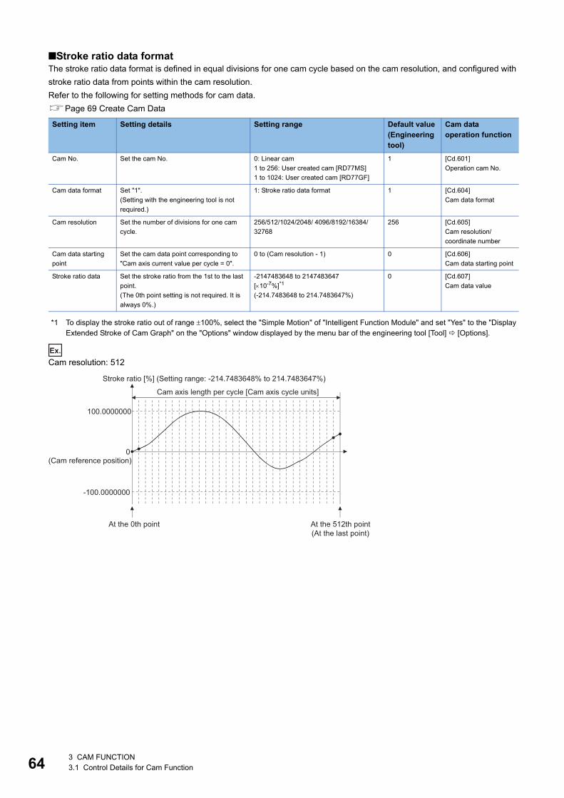
64
■Stroke ratio data formatThe stroke ratio data format is defined in equal divisions for one cam cycle based on the cam resolution, and configured with
stroke ratio data from points within the cam resolution.
Refer to the following for setting methods for cam data.
Page 69 Create Cam Data
*1 To display the stroke ratio out of range 100%, select the "Simple Motion" of "Intelligent Function Module" and set "Yes" to the "DisplayExtended Stroke of Cam Graph" on the "Options" window displayed by the menu bar of the engineering tool [Tool] [Options].
Ex.
Cam resolution: 512
Setting item Setting details Setting range Default value(Engineering tool)
Cam data operation function
Cam No. Set the cam No. 0: Linear cam
1 to 256: User created cam [RD77MS]
1 to 1024: User created cam [RD77GF]
1 [Cd.601]
Operation cam No.
Cam data format Set "1".
(Setting with the engineering tool is not
required.)
1: Stroke ratio data format 1 [Cd.604]
Cam data format
Cam resolution Set the number of divisions for one cam
cycle.
256/512/1024/2048/ 4096/8192/16384/
32768
256 [Cd.605]
Cam resolution/
coordinate number
Cam data starting
point
Set the cam data point corresponding to
"Cam axis current value per cycle = 0".
0 to (Cam resolution - 1) 0 [Cd.606]
Cam data starting point
Stroke ratio data Set the stroke ratio from the 1st to the last
point.
(The 0th point setting is not required. It is
always 0%.)
-2147483648 to 2147483647
[10-7%]*1
(-214.7483648 to 214.7483647%)
0 [Cd.607]
Cam data value
100.0000000
0
-100.0000000
(Cam reference position)
Cam axis length per cycle [Cam axis cycle units]
Stroke ratio [%] (Setting range: -214.7483648% to 214.7483647%)
At the 0th point At the 512th point(At the last point)
3 CAM FUNCTION3.1 Control Details for Cam Function
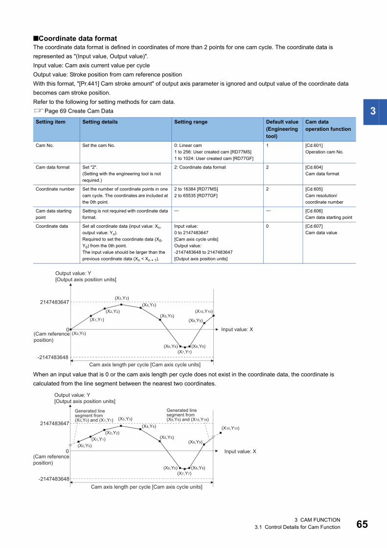
3
■Coordinate data formatThe coordinate data format is defined in coordinates of more than 2 points for one cam cycle. The coordinate data is
represented as "(Input value, Output value)".
Input value: Cam axis current value per cycle
Output value: Stroke position from cam reference position
With this format, "[Pr.441] Cam stroke amount" of output axis parameter is ignored and output value of the coordinate data
becomes cam stroke position.
Refer to the following for setting methods for cam data.
Page 69 Create Cam Data
When an input value that is 0 or the cam axis length per cycle does not exist in the coordinate data, the coordinate is
calculated from the line segment between the nearest two coordinates.
Setting item Setting details Setting range Default value(Engineering tool)
Cam data operation function
Cam No. Set the cam No. 0: Linear cam
1 to 256: User created cam [RD77MS]
1 to 1024: User created cam [RD77GF]
1 [Cd.601]
Operation cam No.
Cam data format Set "2".
(Setting with the engineering tool is not
required.)
2: Coordinate data format 2 [Cd.604]
Cam data format
Coordinate number Set the number of coordinate points in one
cam cycle. The coordinates are included at
the 0th point.
2 to 16384 [RD77MS]
2 to 65535 [RD77GF]
2 [Cd.605]
Cam resolution/
coordinate number
Cam data starting
point
Setting is not required with coordinate data
format.
[Cd.606]
Cam data starting point
Coordinate data Set all coordinate data (input value: Xn,
output value: Yn).
Required to set the coordinate data (X0,
Y0) from the 0th point.
The input value should be larger than the
previous coordinate data (Xn < Xn + 1).
Input value:
0 to 2147483647
[Cam axis cycle units]
Output value:
-2147483648 to 2147483647
[Output axis position units]
0 [Cd.607]
Cam data value
(X0,Y0)
(X1,Y1)
(X2,Y2)
(X3,Y3)(X4,Y4)
(X5,Y5)
(X6,Y6)(X7,Y7)
(X8,Y8)
(X9,Y9)
(X10,Y10)
2147483647
-2147483648
0 Input value: X
Cam axis length per cycle [Cam axis cycle units]
(Cam reference position)
Output value: Y[Output axis position units]
(X0,Y0)(X1,Y1)
(X2,Y2)
(X3,Y3)(X4,Y4)
(X5,Y5)
(X6,Y6)(X7,Y7)
(X8,Y8)
(X9,Y9)
(X10,Y10)2147483647
-2147483648
0 Input value: X
Cam axis length per cycle [Cam axis cycle units]
(Cam reference position)
Output value: Y[Output axis position units]
Generated line segment from(X0,Y0) and (X1,Y1)
Generated line segment from(X9,Y9) and (X10,Y10)
3 CAM FUNCTION3.1 Control Details for Cam Function 65
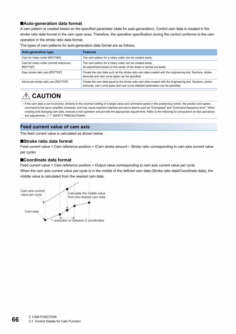
66
■Auto-generation data formatA cam pattern is created based on the specified parameter (data for auto-generation). Control cam data is created in the
stroke ratio data format in the cam open area. Therefore, the operation specification during the control conforms to the cam
operation in the stroke ratio data format.
The types of cam patterns for auto-generation data format are as follows.
Feed current value of cam axisThe feed current value is calculated as shown below.
■Stroke ratio data formatFeed current value = Cam reference position + (Cam stroke amount Stroke ratio corresponding to cam axis current value
per cycle)
■Coordinate data formatFeed current value = Cam reference position + Output value corresponding to cam axis current value per cycle
When the cam axis current value per cycle is in the middle of the defined cam data (Stroke ratio data/Coordinate data), the
middle value is calculated from the nearest cam data.
Auto-generation type Features
Cam for rotary cutter [RD77MS] The cam pattern for a rotary cutter can be created easily.
Cam for rotary cutter (central reference)
[RD77GF]
The cam pattern for a rotary cutter can be created easily.
An adjustment based on the center of the sheet is carried out easily.
Easy stroke ratio cam [RD77GF] Create the cam data such as the stroke ratio cam data created with the engineering tool. Sections, stroke
amounts and cam curve types can be specified.
Advanced stroke ratio cam [RD77GF] Create the cam data equal to the stroke ratio cam data created with the engineering tool. Sections, stroke
amounts, cam curve types and cam curve detailed parameters can be specified.
CAUTION• If the cam data is set incorrectly, similarly to the incorrect setting of a target value and command speed in the positioning control, the position and speed
command to the servo amplifier increases, and may cause machine interface and servo alarms such as "Overspeed" and "Command frequency error". When
creating and changing cam data, execute a trial operation and provide the appropriate adjustments. Refer to the following for precautions on test operations
and adjustments. (SAFETY PRECAUTIONS)
1 resolution or between 2 coordinates
Calculate the middle valuefrom the nearest cam data.
Cam axis currentvalue per cycle
Cam data
3 CAM FUNCTION3.1 Control Details for Cam Function

3
Cam reference positionThe cam reference position is calculated as shown below.
■Stroke ratio data formatCam reference position = The preceding cam reference position + (Cam stroke amount Stroke ratio at the last point)
■Coordinate data formatCam reference position = The preceding cam reference position + Output value corresponding to "Input value = Cam axis
length per cycle" - Output value corresponding to "Input value = 0"
Create cam data for two-way cam operation as shown below.
■Stroke ratio data formatCreate cam data so that the stroke ratio is 0% at the last point.
■Coordinate data formatCreate cam data with the same output value for the point where the input value is 0 and the input value is equal to the cam
axis length per cycle.
t
t
Cam axis currentvalue per cycle
Feed currentvalue
Cam referenceposition(At 3rd cycle)
Cam referenceposition(At 2nd cycle)
Cam referenceposition(At 1st cycle)
Stroke ratio data format:Cam stroke amount × Stroke ratio at last point
Coordinate data format:(The output value corresponding to "Input value = Cam axis length per cycle") - (The output value corresponding to "Input value = 0")
t
t
Cam axis currentvalue per cycle
Feed current value
Cam reference position(Does not change because of the strokeratio 0% and output value = 0.)
3 CAM FUNCTION3.1 Control Details for Cam Function 67

68
Cam data starting pointThis setting is only valid for cam data using the stroke ratio data format.
The cam data point corresponding to "Cam axis current value per cycle = 0" can be set as the cam data starting point.
The default value of the cam data starting point is 0. (The cam axis is controlled with cam data starting from the 0th point
(stroke ratio 0%).)
When a value other than 0 is set for the cam data starting point, cam control is started from the point where the stroke ratio is
not 0%.
The cam data starting point is set for each cam data. The setting range is from 0 to (cam resolution - 1).
Timing of applying cam control data
■Stroke ratio data formatIf "[Pr.439] Cam axis length per cycle", "[Pr.440] Cam No." or "[Pr.441] Cam stroke amount" is changed during synchronous
control, the new value is accepted and applied when the cam axis current value per cycle passes through the 0th point of cam
data, or is on the 0th point.
The cam reference position is updated when the cam axis current value per cycle passes through the 0th point of cam data.
■Coordinate data formatIf "[Pr.439] Cam axis length per cycle" or "[Pr.440] Cam No." is changed during synchronous control, the new value is
accepted and applied when the cam axis current value per cycle passes through 0, or is on 0.
The cam reference position is updated when the cam axis current value per cycle passes through 0.
t
t
Cam axis currentvalue per cycle
Feed current value
Cam referenceposition(At 2nd cycle)
Cam referenceposition(At 1st cycle)
Cam referenceposition(At 3rd cycle)
Cam datastarting point
At the 0th point At last point
3 CAM FUNCTION3.1 Control Details for Cam Function
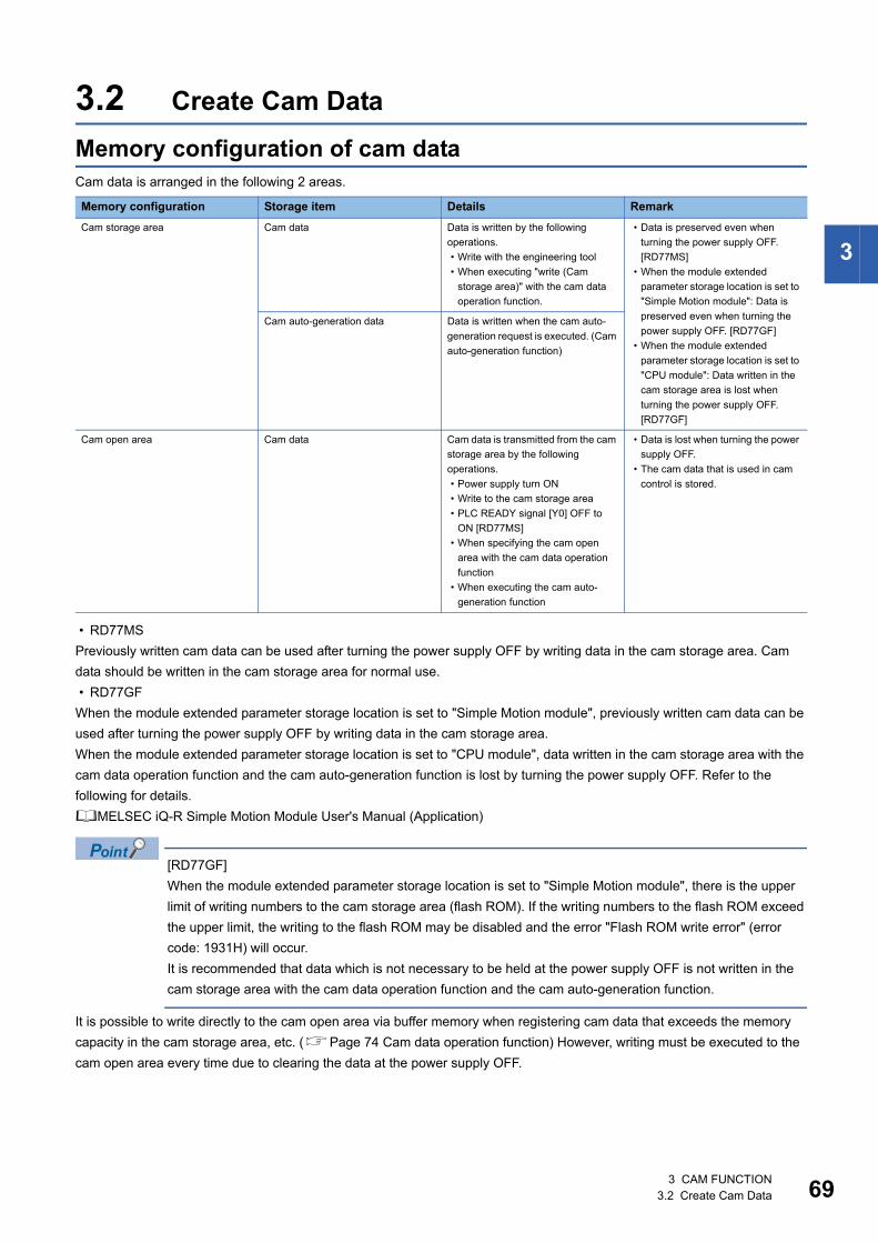
3
3.2 Create Cam Data
Memory configuration of cam dataCam data is arranged in the following 2 areas.
• RD77MS
Previously written cam data can be used after turning the power supply OFF by writing data in the cam storage area. Cam
data should be written in the cam storage area for normal use.
• RD77GF
When the module extended parameter storage location is set to "Simple Motion module", previously written cam data can be
used after turning the power supply OFF by writing data in the cam storage area.
When the module extended parameter storage location is set to "CPU module", data written in the cam storage area with the
cam data operation function and the cam auto-generation function is lost by turning the power supply OFF. Refer to the
following for details.
MELSEC iQ-R Simple Motion Module User's Manual (Application)
[RD77GF]
When the module extended parameter storage location is set to "Simple Motion module", there is the upper
limit of writing numbers to the cam storage area (flash ROM). If the writing numbers to the flash ROM exceed
the upper limit, the writing to the flash ROM may be disabled and the error "Flash ROM write error" (error
code: 1931H) will occur.
It is recommended that data which is not necessary to be held at the power supply OFF is not written in the
cam storage area with the cam data operation function and the cam auto-generation function.
It is possible to write directly to the cam open area via buffer memory when registering cam data that exceeds the memory
capacity in the cam storage area, etc. (Page 74 Cam data operation function) However, writing must be executed to the
cam open area every time due to clearing the data at the power supply OFF.
Memory configuration Storage item Details Remark
Cam storage area Cam data Data is written by the following
operations.
• Write with the engineering tool
• When executing "write (Cam
storage area)" with the cam data
operation function.
• Data is preserved even when
turning the power supply OFF.
[RD77MS]
• When the module extended
parameter storage location is set to
"Simple Motion module": Data is
preserved even when turning the
power supply OFF. [RD77GF]
• When the module extended
parameter storage location is set to
"CPU module": Data written in the
cam storage area is lost when
turning the power supply OFF.
[RD77GF]
Cam auto-generation data Data is written when the cam auto-
generation request is executed. (Cam
auto-generation function)
Cam open area Cam data Cam data is transmitted from the cam
storage area by the following
operations.
• Power supply turn ON
• Write to the cam storage area
• PLC READY signal [Y0] OFF to
ON [RD77MS]
• When specifying the cam open
area with the cam data operation
function
• When executing the cam auto-
generation function
• Data is lost when turning the power
supply OFF.
• The cam data that is used in cam
control is stored.
3 CAM FUNCTION3.2 Create Cam Data 69
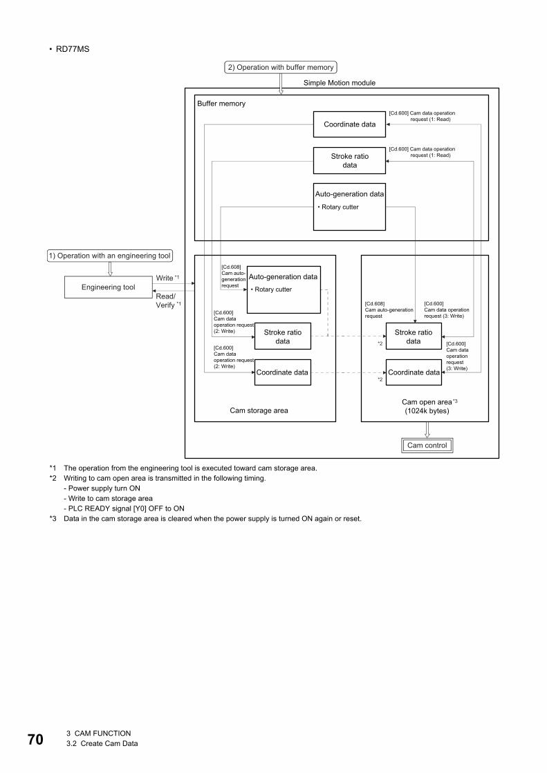
70
• RD77MS
*1 The operation from the engineering tool is executed toward cam storage area.*2 Writing to cam open area is transmitted in the following timing.
- Power supply turn ON- Write to cam storage area- PLC READY signal [Y0] OFF to ON
*3 Data in the cam storage area is cleared when the power supply is turned ON again or reset.
Buffer memory
Coordinate data
Stroke ratiodata
Auto-generation data
• Rotary cutter
Engineering tool
1) Operation with an engineering tool
Write *1
Read/Verify *1
2) Operation with buffer memory
[Cd.600] Cam data operation request (1: Read)
[Cd.600] Cam data operation request (1: Read)
Auto-generation data
Coordinate data Coordinate data
Stroke ratiodata
Cam control
Cam open area(1024k bytes)Cam storage area
*2
*2
[Cd.608] Cam auto-generationrequest
[Cd.600]Cam data operationrequest (3: Write)
Simple Motion module
Stroke ratiodata
• Rotary cutter
[Cd.608] Cam auto-generationrequest
[Cd.600]Cam dataoperationrequest(3: Write)
[Cd.600]Cam dataoperation request(2: Write)
[Cd.600]Cam dataoperation request(2: Write)
*3
3 CAM FUNCTION3.2 Create Cam Data

3
• RD77GF
*1 The operation from the engineering tool is executed toward cam storage area.*2 Writing to cam open area is transmitted in the following timing.
- Power supply turn ON- When "5: Transfer" is set in "[Cd.600] Cam data operation request"
*3 Data in the cam storage area is cleared when the power supply is turned ON again or reset.
Buffer memory
Coordinate data
Stroke ratiodata
Auto-generationdata
• Rotary cutter• Easy stroke ratio• Advanced stroke ratio
Engineering tool
1) Operation with an engineering tool
Write*1
Read/Verify *1
2) Operation with buffer memory
[Cd.600] Cam data operation request (1: Read)
[Cd.600] Cam data operation request (1: Read)
[Cd.600] Cam data operation request (4: Read)
[Cd.600] Cam data operation request (4: Read)
[Cd.600] Cam data operation request (4: Read)
Auto-generationdata
Coordinate data Coordinate data
Stroke ratiodata
Cam control
Cam open area(16M bytes)
*3
Cam storage area
*2
*2
[Cd.608] Cam auto-generationrequest
[Cd.600]Cam data operationrequest (3: Write)
Simple Motion module
Stroke ratiodata
• Rotary cutter• Easy stroke ratio• Advanced stroke ratio [Cd.608]
Cam auto-generationrequest
[Cd.600]Cam dataoperationrequest(3: Write)
[Cd.600]Cam dataoperation request(2: Write)
[Cd.600]Cam dataoperation request(2: Write)
3 CAM FUNCTION3.2 Create Cam Data 71
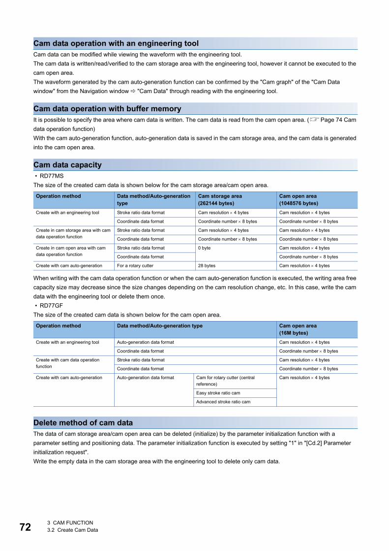
72
Cam data operation with an engineering toolCam data can be modified while viewing the waveform with the engineering tool.
The cam data is written/read/verified to the cam storage area with the engineering tool, however it cannot be executed to the
cam open area.
The waveform generated by the cam auto-generation function can be confirmed by the "Cam graph" of the "Cam Data
window" from the Navigation window "Cam Data" through reading with the engineering tool.
Cam data operation with buffer memoryIt is possible to specify the area where cam data is written. The cam data is read from the cam open area. (Page 74 Cam
data operation function)
With the cam auto-generation function, auto-generation data is saved in the cam storage area, and the cam data is generated
into the cam open area.
Cam data capacity • RD77MS
The size of the created cam data is shown below for the cam storage area/cam open area.
When writing with the cam data operation function or when the cam auto-generation function is executed, the writing area free
capacity size may decrease since the size changes depending on the cam resolution change, etc. In this case, write the cam
data with the engineering tool or delete them once.
• RD77GF
The size of the created cam data is shown below for the cam open area.
Delete method of cam dataThe data of cam storage area/cam open area can be deleted (initialize) by the parameter initialization function with a
parameter setting and positioning data. The parameter initialization function is executed by setting "1" in "[Cd.2] Parameter
initialization request".
Write the empty data in the cam storage area with the engineering tool to delete only cam data.
Operation method Data method/Auto-generation type
Cam storage area(262144 bytes)
Cam open area(1048576 bytes)
Create with an engineering tool Stroke ratio data format Cam resolution 4 bytes Cam resolution 4 bytes
Coordinate data format Coordinate number 8 bytes Coordinate number 8 bytes
Create in cam storage area with cam
data operation function
Stroke ratio data format Cam resolution 4 bytes Cam resolution 4 bytes
Coordinate data format Coordinate number 8 bytes Coordinate number 8 bytes
Create in cam open area with cam
data operation function
Stroke ratio data format 0 byte Cam resolution 4 bytes
Coordinate data format Coordinate number 8 bytes
Create with cam auto-generation For a rotary cutter 28 bytes Cam resolution 4 bytes
Operation method Data method/Auto-generation type Cam open area(16M bytes)
Create with an engineering tool Auto-generation data format Cam resolution 4 bytes
Coordinate data format Coordinate number 8 bytes
Create with cam data operation
function
Stroke ratio data format Cam resolution 4 bytes
Coordinate data format Coordinate number 8 bytes
Create with cam auto-generation Auto-generation data format Cam for rotary cutter (central
reference)
Cam resolution 4 bytes
Easy stroke ratio cam
Advanced stroke ratio cam
3 CAM FUNCTION3.2 Create Cam Data

3
Password protection for cam dataThe cam data can be protected as shown below by password setting.
[RD77GF]
The password is set as follows.
• When the module extended parameter storage location is set to "Simple Motion module":
Set using the Simple Motion module setting function of the engineering tool.
• When the module extended parameter storage location is set to "CPU module":
Set using the file password of the module extended parameters (For the cam data operation with buffer
memory, it is based on the file password status of the module extended parameters.)
The password for cam data is deleted with cam data by "[Cd.2] Parameter initialization request". (When the module extended
parameter storage location is set to "Simple Motion module" [RD77GF])
Password setting Cam data operation with an engineering tool Cam data operation with buffer memory
Password for read protection Cam data cannot be read without unlocking the password
for read protection.
Reading cam data is not operated.
Password for write protection Cam data cannot be written without unlocking the
password for write protection.
Writing cam data and generating cam data auto-
generation is not operated.
3 CAM FUNCTION3.2 Create Cam Data 73
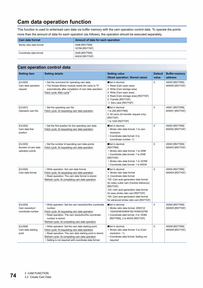
74
Cam data operation functionThis function is used to write/read cam data via buffer memory with the cam operation control data. To operate the points
more than the amount of data for each operation (as follows), the operation should be executed separately.
Cam operation control data
Cam data format Amount of data for each operation
Stroke ratio data format 4096 [RD77MS]
32768 [RD77GF]
Coordinate data format 2048 [RD77MS]
65535 [RD77GF]
Setting item Setting details Setting value(Read operation: Stored value)
Default value
Buffer memory address
[Cd.600]
Cam data operation
request
• Set the command for operating cam data.
• The Simple Motion module resets the value to "0"
automatically after completion of cam data operation.
Fetch cycle: Main cycle*1
■Set in decimal.
1: Read (Cam open area)
2: Write (Cam storage area)
3: Write (Cam open area)
4: Read (Cam storage area) [RD77GF]
5: Transfer [RD77GF]
-1: Zero clear [RD77GF]
0 45000 [RD77MS]
600000 [RD77GF]
[Cd.601]
Operation cam No.
• Set the operating cam No.
Fetch cycle: At requesting cam data operation
■Set in decimal.
1 to 256 [RD77MS]
0: All cams (At transfer request only)
[RD77GF]
1 to 1024 [RD77GF]
0 45001 [RD77MS]
600001 [RD77GF]
[Cd.602]
Cam data first
position
• Set the first position for the operating cam data.
Fetch cycle: At requesting cam data operation
■Set in decimal.
• Stroke ratio data format: 1 to cam
resolution
• Coordinate data format: 0 to
(coordinate number -1)
0 45002 [RD77MS]
600002 [RD77GF]
[Cd.603]
Number of cam data
operation points
• Set the number of operating cam data points.
Fetch cycle: At requesting cam data operation
■Set in decimal.
[RD77MS]
• Stroke ratio data format: 1 to 4096
• Coordinate data format: 1 to 2048
[RD77GF]
• Stroke ratio data format: 1 to 32768
• Coordinate data format: 1 to 65535
0 45003 [RD77MS]
600003 [RD77GF]
[Cd.604]
Cam data format
• Write operation: Set cam data format.
Fetch cycle: At requesting cam data operation
• Read operation: The cam data format is stored.
Refresh cycle: At completing cam data operation
■Set in decimal.
1: Stroke ratio data format
2: Coordinate data format
102: Cam auto-generation data format
for rotary cutter cam (Central reference)
[RD77GF]
103: Cam auto-generation data format
for easy stroke ratio cam [RD77GF]
104: Cam auto-generation data format
for advanced stroke ratio cam [RD77GF]
0 45004 [RD77MS]
600004 [RD77GF]
[Cd.605]
Cam resolution/
coordinate number
• Write operation: Set the cam resolution/the coordinate
number.
Fetch cycle: At requesting cam data operation
• Read operation: The cam resolution/the coordinate
number is stored.
Refresh cycle: At completing cam data operation
■Set in decimal.
• Stroke ratio data format: 256/512/
1024/2048/4096/8192/16384/32768
• Coordinate data format: 2 to 16384
[RD77MS], 2 to 65535 [RD77GF]
0 45005 [RD77MS]
600005 [RD77GF]
[Cd.606]
Cam data starting
point
• Write operation: Set the cam data starting point.
Fetch cycle: At requesting cam data operation
• Read operation: The cam data starting point is stored.
Refresh cycle: At completing cam data operation
• Setting is not required with coordinate data format.
■Set in decimal.
• Stroke ratio data format: 0 to (Cam
resolution - 1)
• Coordinate data format: Setting not
required
0 45006 [RD77MS]
600006 [RD77GF]
3 CAM FUNCTION3.2 Create Cam Data

3
*1 With the exception of positioning control, main cycle processing is executed during the next available time. It changes by status of axis start.*2 Cam axis cycle units (Page 126 Units for the output axis)*3 Output axis position units (Page 126 Units for the output axis)
[Cd.600] Cam data operation requestSet the following commands to write/read cam data.
The setting value is reset to "0" automatically after completion of cam data operation.
If a warning occurs when requesting cam data operation, the warning No. is stored in "[Md.24] Axis warning No." of axis 1,
and the setting value is reset to "0" automatically.
When another request command is set, the operation does not get executed and the setting value is reset to "0" automatically.
[Cd.601] Operation cam No.Set the cam No. to write/read.
[Cd.602] Cam data first positionSet the first position of the cam data to write/read.
Set the cam data first position within the range from 1 to the cam resolution in cam resolution units using the stroke ratio data
format. The stroke ratio of the 0th cam data is 0% fixed, and this data cannot be written/read.
Set a value within the range from 0 to (Coordinate number - 1) with the coordinate data format.
[Cd.607]
Cam data value
• Write operation: Set the cam data corresponding to the
cam data format.
Fetch cycle: At requesting cam data operation
• Read operation: The cam data is stored.
Refresh cycle: At completing cam data operation
■Set in decimal.
• Stroke ratio data format
-2147483648 to 2147483647 [ 10-7%]
• Coordinate data format
Input value: 0 to 2147483647
[Cam axis cycle units*2]
Output value: -2147483648 to
2147483647
[Output axis position units*3]
0 45008 to 53199
[RD77MS]
600008 to 862147
[RD77GF]
Setting value Details
1: Read (Cam open area) The cam data is read from the cam open area and stored to the buffer memory.
2: Write (Cam storage area) The cam data is written to the cam storage area and the cam open area from the buffer memory.
3: Write (Cam open area) The cam data is written to the cam open area from the buffer memory.
4: Read (Cam storage area)
[RD77GF]
The data is read from the cam storage area and stored to the buffer memory.
5: Transfer [RD77GF] The data is written to the cam open area from the cam storage area.
-1: Zero clear [RD77GF] All the buffer memories of "[Cd.607] Cam data value" are cleared to 0.
Setting item Setting details Setting value(Read operation: Stored value)
Default value
Buffer memory address
3 CAM FUNCTION3.2 Create Cam Data 75

76
[Cd.603] Number of cam data operation pointsSet the number of operation points to write/read starting from the first position of cam data.
• Stroke ratio data format
The following shows the operation details when the value of "Cam data first position + Cam data operation points - 1" is larger
than the cam resolution in the stroke ratio data format.
• Coordinate data format
The following shows the operation details when the value of "Cam data first position + Cam data operation points" is larger
than the coordinate number with the coordinate data format.
[Cd.604] Cam data formatSet one of the following cam data formats.
• RD77MS
• RD77GF
[Cd.605] Cam resolution/coordinate numberSet/load the cam resolution/the coordinate number.
[Cd.606] Cam data starting pointSet/load the cam data starting point. This is used with the stroke ratio data format.
Operation Details
Reading The cam data from the first position to the cam resolution is read in the buffer memory.
Writing The warning "Outside number of cam data operation points range" (warning code: 0C43H) occurs, and writing is not
executed.
Operation Details
Reading The cam data from the first position to the last coordinate is read in the buffer memory.
Writing The warning "Outside number of cam data operation points range" (warning code: 0C43H) occurs, and writing is not
executed.
Setting value Details
1 Stroke ratio data format
2 Coordinate data format
Setting value Details
Reading (Cam open area) 1: Stroke ratio data format
2: Coordinate data format
Reading (Cam storage area) 1: Stroke ratio data format
2: Coordinate data format
102: Cam auto-generation data format for rotary cutter cam (Central reference)
103: Cam auto-generation data format for easy stroke ratio cam
104: Cam auto-generation data format for advanced stroke ratio cam
Writing 1: Stroke ratio data format
2: Coordinate data format
Operation Details
Reading The cam resolution/the coordinate number of the set cam data is read.
Writing Set the cam resolution with the following values when using the stroke ratio data format.
256/512/1024/2048/4096/8192/16384/32768
Set the coordinate number within the following range when using the coordinate data format.
2 to 16384 [RD77MS], 2 to 65535 [RD77GF]
Operation Details
Reading The cam starting point of the set cam data is read.
Writing Set the cam data starting point within the range from 0 to (Cam resolution - 1).
3 CAM FUNCTION3.2 Create Cam Data

3
[Cd.607] Cam data valueSet/load the cam data operation points according to one of the following formats.
■Stroke ratio data format • RD77MS
• RD77GF
■Coordinate data format • RD77MS
• RD77GF
Buffer memory address Item Setting value
45008
45009
Stroke ratio at first point -2147483648 to 2147483647 [ 10-7%]
(-214.7483648 to 214.7483647 [%])
45010
45011
Stroke ratio at second point
53198
53199
Stroke ratio at 4096th point
Buffer memory address Item Setting value
600008
600009
Stroke ratio at first point -2147483648 to 2147483647 [ 10-7%]
(-214.7483648 to 214.7483647 [%])
600010
600011
Stroke ratio at second point
862146
862147
Stroke ratio at 32768th point
Buffer memory address Item Setting value
45008
45009
At first point Input value 0 to 2147483647
[Cam axis cycle unit]
45010
45011
Output value -2147483648 to 2147483647
[Output axis position unit]
45012
45013
At second point Input value 0 to 2147483647
[Cam axis cycle unit]
45014
45015
Output value -2147483648 to 2147483647
[Output axis position unit]
53196
53197
At 2048th point Input value 0 to 2147483647
[Cam axis cycle unit]
53198
53199
Output value -2147483648 to 2147483647
[Output axis position unit]
Buffer memory address Item Setting value
600008
600009
At first point Input value 0 to 2147483647
[Cam axis cycle unit]
600010
600011
Output value -2147483648 to 2147483647
[Output axis position unit]
600012
600013
At second point Input value 0 to 2147483647
[Cam axis cycle unit]
600014
600015
Output value -2147483648 to 2147483647
[Output axis position unit]
862144
862145
At 65535th point Input value 0 to 2147483647
[Cam axis cycle unit]
862146
862147
Output value -2147483648 to 2147483647
[Output axis position unit]
3 CAM FUNCTION3.2 Create Cam Data 77
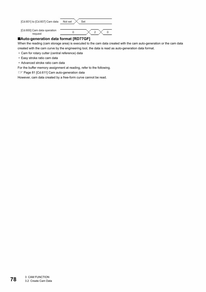
78
■Auto-generation data format [RD77GF]When the reading (cam storage area) is executed to the cam data created with the cam auto-generation or the cam data
created with the cam curve by the engineering tool, the data is read as auto-generation data format.
• Cam for rotary cutter (central reference) data
• Easy stroke ratio cam data
• Advanced stroke ratio cam data
For the buffer memory assignment at reading, refer to the following.
Page 81 [Cd.611] Cam auto-generation data
However, cam data created by a free-form curve cannot be read.
0 02
[Cd.601] to [Cd.607] Cam data Not set Set
[Cd.600] Cam data operation request
3 CAM FUNCTION3.2 Create Cam Data
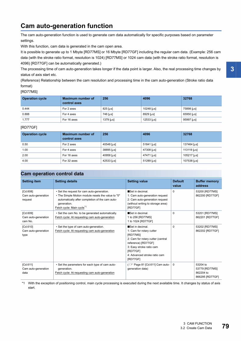
3
Cam auto-generation functionThe cam auto-generation function is used to generate cam data automatically for specific purposes based on parameter
settings.
With this function, cam data is generated in the cam open area.
It is possible to generate up to 1 Mbyte [RD77MS] or 16 Mbyte [RD77GF] including the regular cam data. (Example: 256 cam
data (with the stroke ratio format, resolution is 1024) [RD77MS] or 1024 cam data (with the stroke ratio format, resolution is
4096) [RD77GF] can be automatically generated.)
The processing time of cam auto-generation takes longer if the data point is larger. Also, the real processing time changes by
status of axis start etc.
(Reference) Relationship between the cam resolution and processing time in the cam auto-generation (Stroke ratio data
format)
[RD77MS]
[RD77GF]
Cam operation control data
*1 With the exception of positioning control, main cycle processing is executed during the next available time. It changes by status of axis start.
Operation cycle Maximum number of control axes
256 4096 32768
0.444 For 2 axes 825 [s] 10248 [s] 75898 [s]
0.888 For 4 axes 746 [s] 8929 [s] 65950 [s]
1.777 For 16 axes 1379 [s] 12533 [s] 95997 [s]
Operation cycle Maximum number of control axes
256 4096 32768
0.50 For 2 axes 40548 [s] 51841 [s] 137464 [s]
1.00 For 4 axes 38895 [s] 47308 [s] 113119 [s]
2.00 For 16 axes 40958 [s] 47471 [s] 105217 [s]
4.00 For 32 axes 42533 [s] 51289 [s] 107538 [s]
Setting item Setting details Setting value Default value
Buffer memory address
[Cd.608]
Cam auto-generation
request
• Set the request for cam auto-generation.
• The Simple Motion module resets the value to "0"
automatically after completion of the cam auto-
generation.
Fetch cycle: Main cycle*1
■Set in decimal.
1: Cam auto-generation request
2: Cam auto-generation request
(without writing to storage area)
[RD77GF]
0 53200 [RD77MS]
862200 [RD77GF]
[Cd.609]
Cam auto-generation
cam No.
• Set the cam No. to be generated automatically.
Fetch cycle: At requesting cam auto-generation
■Set in decimal.
1 to 256 [RD77MS]
1 to 1024 [RD77GF]
0 53201 [RD77MS]
862201 [RD77GF]
[Cd.610]
Cam auto-generation
type
• Set the type of cam auto-generation.
Fetch cycle: At requesting cam auto-generation
■Set in decimal.
1: Cam for rotary cutter
[RD77MS]
2: Cam for rotary cutter (central
reference) [RD77GF]
3: Easy stroke ratio cam
[RD77GF]
4: Advanced stroke ratio cam
[RD77GF]
0 53202 [RD77MS]
862202 [RD77GF]
[Cd.611]
Cam auto-generation
data
• Set the parameters for each type of cam auto-
generation.
Fetch cycle: At requesting cam auto-generation
(Page 81 [Cd.611] Cam auto-
generation data)
0 53204 to
53779 [RD77MS]
862204 to
866295 [RD77GF]
3 CAM FUNCTION3.2 Create Cam Data 79
80
[Cd.608] Cam auto-generation requestSet "1: Cam auto-generation request" or "2: Cam auto-generation request (without writing to storage area)" [RD77GF] to
execute cam auto-generation.
Cam data is generated in the cam open area of the specified cam No. based on the cam auto-generation data.
The setting value is reset to "0" automatically after completing the process.
The cam auto-generation data is saved in the cam storage area. The cam auto-generation is executed automatically again
when the next power supply turns ON or PLC READY signal [Y0] OFF to ON. [RD77MS]
When "1: Cam auto-generation request" is set and the module extended parameter storage location is set to "Simple Motion
module", the cam auto-generation data is saved in the cam storage area (flash ROM). The cam auto-generation is executed
automatically again when the next power supply turns ON or "5: Transfer" is set in "[Cd.600] Cam data operation request".
[RD77GF]
If a warning occurs when requesting cam auto-generation, the warning No. is stored in "[Md.24] Axis warning No." of axis 1,
and the setting value is reset to "0" automatically.
When another request command is set, this function does not get executed and the setting value is reset to "0" automatically.
[Cd.609] Cam auto-generation cam No.Set the cam No. to be generated automatically.
[Cd.610] Cam auto-generation typeSet the type of cam auto-generation.
3 CAM FUNCTION3.2 Create Cam Data

3
[Cd.611] Cam auto-generation dataSet the cam auto-generation data corresponding to "[Cd.610] Cam auto-generation type".
■Cam auto-generation data for rotary cutter [RD77MS]The cam data starting point for a rotary cutter is 0.
Buffer memory address Item Setting value Details
53204 Cam resolution 256/512/1024/2048/4096/8192/16384/32768 Set the cam resolution for generating the cam.
53206
53207
Sheet length 1 to 2147483647
[(Optional) Same unit (0.1 mm, etc.)]
Set the sheet length.
Set this value in the cam axis length per cycle.
53208
53209
Sheet
synchronization
width
1 to 2147483647
[(Optional) Same unit (0.1 mm, etc.)]
Set the sheet length of the synchronous section.
53210
53211
Synchronous
axis length
1 to 2147483647
[(Optional) Same unit (0.1 mm, etc.)]
Set the cycle length of the rotary cutter shaft.
53212
53213
Synchronization
starting point
0 to 2147483647
[(Optional) Same unit (0.1 mm, etc.)]
Set the length from the beginning of the sheet to the start
of the synchronous section.
53214 Synchronous
section
acceleration
ratio
-5000 to 5000 [0.01%] Set when the synchronous speed in the synchronous
section needs to be adjusted.
The speed is "Synchronous speed (100% +
Acceleration ratio)" in the synchronous section.
Sheet synchronization width
Synchronization starting point
Cam axis current value per cycle
t
Sheet length
Sheet length
Sheet synchronization width
Synchronousaxis
(Cam axis)
Synchronization starting point
Synchronous axis length Synchronous axis cycle length
Feed sheet
t
Synchronous section acceleration ratio
t
100%
Cam stroke ratio(Cam data by auto-generation)
When 0%, it is as fast as synchronous speed.
Cam axis (Synchronous axis) speedSynchronous speed(Feed sheet speed)
3 CAM FUNCTION3.2 Create Cam Data 81

82
■Cam auto-generation data for rotary cutter (central reference) [RD77GF]When the synchronous position adjustment is set to 0, the cam pattern of which the sheet center is in the synchronous section
is created.
Buffer memory address
Item Setting value Details
862204
862205
Cam resolution 256/512/1024/2048/4096/8192/16384/32768 Set the cam resolution for generating the cam.
862206 Auto-generation
option
• Bit 0: Acceleration/deceleration system
0: Trapezoidal acceleration/deceleration
1: S-curve acceleration/deceleration
• Bit1: Synchronous axis length setting
0: Diameter
1: Cycle length
• Select the trapezoidal acceleration/deceleration system or
the S-curve acceleration/deceleration system with bit 0.
• Select the diameter or the cycle length for the synchronous
axis length setting with bit 1.
• Set "0" for bit 2 to 15.
862207 Synchronous section
acceleration ratio
-5000 to 5000 [0.01%] Set when the synchronous speed in the synchronous section
needs to be adjusted.
The speed is "Synchronous speed (100% + Acceleration
ratio)" in the synchronous section.
862208
862209
Sheet length 1 to 2147483647
[(Optional) Same units]
Set the sheet length.
862210
862211
Sheet
synchronization
width
1 to 2147483647
[(Optional) Same units]
• Set the sheet synchronization width (seal width).
• When the synchronous speed section for retracting
operation is required in front of and behind the sheet
synchronization width, add the retracting width.
862212
862213
Synchronous axis
length
For diameter setting
1 to 680000000
For cycle length setting
1 to 2147483647
[(Optional) Same units]
• Set the rotary cutter axis length.
• When the auto-generation option is set to the diameter, it is
calculated as "Cycle length = setting value ".
• When the auto-generation option is set to the cycle length,
it is calculated as "Cycle length = setting value".
862214
862215
Synchronous
position adjustment
-1073741823 to 1073741823
[(Optional) Same units]
• Set the position adjustment of the synchronous section.
Negative value: The synchronous section is adjusted to the
sheet start side.
0: The center of the sheet is in the synchronous section.
Positive value: The synchronous section is adjusted to the
sheet end side.
• Set the value within one-half of the sheet length.
862216
862217
Acceleration/
deceleration width
0 to 2147483647
[(Optional) Same units]
• For a value other than the above, the
acceleration/deceleration width is calculated
to be the maximum.
• Set the sheet width (one side) of the acceleration/
deceleration area.
• When a negative value is set, the acceleration/
deceleration width is calculated to be the maximum.
862218 Number of cutter 1 to 256 Set the number of cutter.
862219 Asynchronous
speed result
0 to 65535 [0.01 times] When the cam auto-generation is successfully performed,
the asynchronous speed is stored as the ratio of the
synchronous speed.
3 CAM FUNCTION3.2 Create Cam Data

3
Ex.
Cam pattern created at the following settings
Acceleration/deceleration system = Trapezoidal, Synchronous axis length setting = Diameter
Synchronous section acceleration ratio = 3.00%
Sheet length = 200.0 mm
Sheet synchronization width = 30.0 mm (Seal section) + 20.0 mm (Retracting operation)
Synchronous axis length = 100.0 mm (Diameter)
Synchronous position adjustment = 20.0 mm
Acceleration/deceleration width = 55.0 mm
Number of cutter = 1
t
t
t
100%
SynchronousaxisSheet synchronization width
Feed sheet
Synchronous axis lengthSynchronous axis cycle length/diameter
Sheet lengthCam axis current value per cycle
Sheet synchronization width
Cam axis (Synchronous axis) speed
Synchronous speed(Feed sheet speed)
Cam stroke ratio(Cam data by auto-generation)
Synchronous section acceleration ratio
Acceleration/deceleration width
Acceleration/deceleration width
Acceleration/deceleration width
Asynchronous speed(Automatically calculated)
Negative value: The synchronous sectionis adjusted to the sheet start side.0: The center of the sheet is in thesynchronous section.Positive value: The synchronous sectionis adjusted to the sheet end side.
Synchronous position adjustment
When 0%, it is as fast as synchronous speed.
Sheet length
SynchronousaxisSheet synchronization width
= 30.0 mm + 20.0 mm
Feed sheet
Synchronous axis length = 100.0 mm (Diameter)
Cam axis (Synchronous axis) speed
Synchronous speed(Feed sheet speed)
t
Synchronous section acceleration ratio = 3.00%
Acceleration/deceleration width = 55.0 mm
Acceleration/deceleration width = 55.0 mm
Asynchronous speed
Center of sheet
(The retracting section is adjusted to the sheet end side.)
Synchronous position adjustment = 20.0 mm
Sea
l sec
tion
Sheet length = 200.0 mm
Ret
ract
ing
sect
ion
3 CAM FUNCTION3.2 Create Cam Data 83
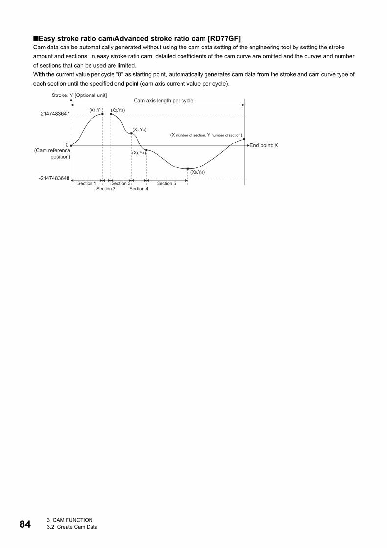
84
■Easy stroke ratio cam/Advanced stroke ratio cam [RD77GF]Cam data can be automatically generated without using the cam data setting of the engineering tool by setting the stroke
amount and sections. In easy stroke ratio cam, detailed coefficients of the cam curve are omitted and the curves and number
of sections that can be used are limited.
With the current value per cycle "0" as starting point, automatically generates cam data from the stroke and cam curve type of
each section until the specified end point (cam axis current value per cycle).
2147483647
-2147483648
(X1,Y1) (X2,Y2)
(X3,Y3)
(X4,Y4)
(X5,Y5)
Stroke: Y [Optional unit]Cam axis length per cycle
(Cam referenceposition)
End point: X
(X number of section, Y number of section)
Section 1 Section 3Section 4
Section 5Section 2
0
3 CAM FUNCTION3.2 Create Cam Data

3
• Easy stroke ratio cam data for auto-generation
*1 The set value is only used for cam data generation. Control is performed by the output axis parameter "[Pr.439] Cam axis length per cycle".
*2 Refer to the following for the shapes of each cam type. Use P1 = 0, P2 = 1.00, and default values for L1 and L2.[Cam curve list]
*3 If setting is outside range, the cam axis length per cycle will be set as the final end point of the section settings.
Buffer memory address
Item Setting value Details
862204
862205
Cam resolution 256/512/1024/2048/4096/
8192/16384/32768
Set the cam resolution for generating the cam.
862206
862207
Cam axis length per cycle*1 1 to 2147483647
[Cam axis length per cycle
units]
Set the required input amount with the cam per cycle.
862208
862209
Cam data starting point 0 to (Resolution - 1) Set the starting point as the point corresponding to "cycle length = 0" of
cam data.
862210 Number of sections 1 to 32 Set the number of sections of cam data.
Set data for the number of sections specified.
862212 Section
1
Cam curve type*2 0: Constant speed
1: Constant acceleration
2: Distorted trapezoid
3: Distorted sine
4: Distorted constant speed
5: Cycloid
6: 5th curve
Set the cam curve.
862214
862215
End point 1 to Cam axis length per cycle
[Cam axis length per cycle
units]*3
Set the point for cam axis length per cycle (cam axis current value per
cycle). It is necessary to set a value larger than the end point
immediately before (Xn < Xn + 1). Also, for the final end point, set as
the cam axis length per cycle.
862216
862217
Stroke -2147483648 to 2147483647
[ 0.0000001%]
Set the stroke position from the cam reference position of when at the
end point specified by cam axis current value per cycle.
When set at "1000000000", it becomes the position set in "[Pr.441]
Cam stroke amount".
862218 Section
2
Cam curve type*2 0: Constant speed
1: Constant acceleration
2: Distorted trapezoid
3: Distorted sine
4: Distorted constant speed
5: Cycloid
6: 5th curve
The data specified by "number of sections" becomes valid.
It is not necessary to set the data after the specified number of
sections.
862220
862221
End point 1 to Cam axis length per cycle
[Cam axis length per cycle
units]*3
862222
862223
Stroke -2147483648 to 2147483647
[ 0.0000001%]
862398 Section
32
Cam curve type*2 0: Constant speed
1: Constant acceleration
2: Distorted trapezoid
3: Distorted sine
4: Distorted constant speed
5: Cycloid
6: 5th curve
862400
862401
End point 1 to Cam axis length per cycle
[Cam axis length per cycle
units]*3
862402
862403
Stroke -2147483648 to 2147483647
[ 0.0000001%]
3 CAM FUNCTION3.2 Create Cam Data 85
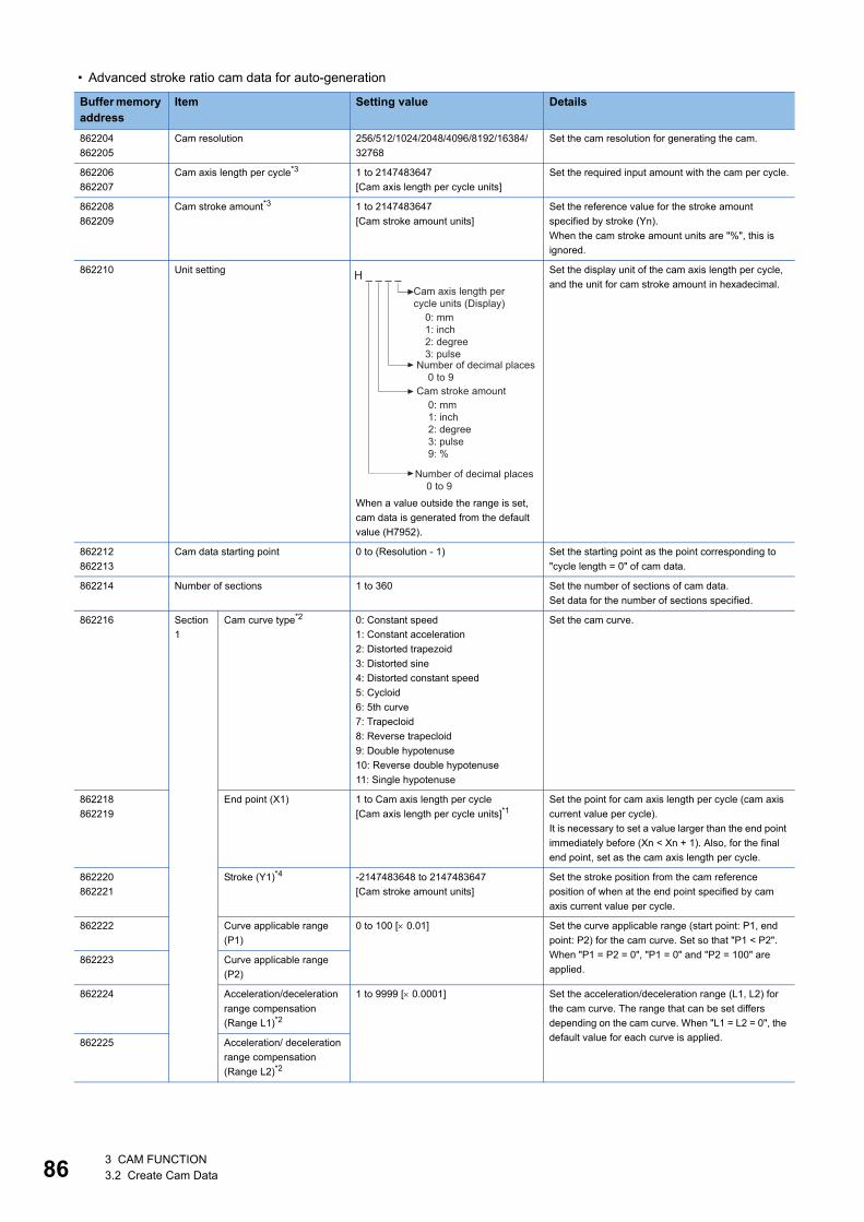
86
• Advanced stroke ratio cam data for auto-generation
Buffer memory address
Item Setting value Details
862204
862205
Cam resolution 256/512/1024/2048/4096/8192/16384/
32768
Set the cam resolution for generating the cam.
862206
862207
Cam axis length per cycle*3 1 to 2147483647
[Cam axis length per cycle units]
Set the required input amount with the cam per cycle.
862208
862209
Cam stroke amount*3 1 to 2147483647
[Cam stroke amount units]
Set the reference value for the stroke amount
specified by stroke (Yn).
When the cam stroke amount units are "%", this is
ignored.
862210 Unit setting
When a value outside the range is set,
cam data is generated from the default
value (H7952).
Set the display unit of the cam axis length per cycle,
and the unit for cam stroke amount in hexadecimal.
862212
862213
Cam data starting point 0 to (Resolution - 1) Set the starting point as the point corresponding to
"cycle length = 0" of cam data.
862214 Number of sections 1 to 360 Set the number of sections of cam data.
Set data for the number of sections specified.
862216 Section
1
Cam curve type*2 0: Constant speed
1: Constant acceleration
2: Distorted trapezoid
3: Distorted sine
4: Distorted constant speed
5: Cycloid
6: 5th curve
7: Trapecloid
8: Reverse trapecloid
9: Double hypotenuse
10: Reverse double hypotenuse
11: Single hypotenuse
Set the cam curve.
862218
862219
End point (X1) 1 to Cam axis length per cycle
[Cam axis length per cycle units]*1Set the point for cam axis length per cycle (cam axis
current value per cycle).
It is necessary to set a value larger than the end point
immediately before (Xn < Xn + 1). Also, for the final
end point, set as the cam axis length per cycle.
862220
862221
Stroke (Y1)*4 -2147483648 to 2147483647
[Cam stroke amount units]
Set the stroke position from the cam reference
position of when at the end point specified by cam
axis current value per cycle.
862222 Curve applicable range
(P1)
0 to 100 [ 0.01] Set the curve applicable range (start point: P1, end
point: P2) for the cam curve. Set so that "P1 < P2".
When "P1 = P2 = 0", "P1 = 0" and "P2 = 100" are
applied.862223 Curve applicable range
(P2)
862224 Acceleration/deceleration
range compensation
(Range L1)*2
1 to 9999 [ 0.0001] Set the acceleration/deceleration range (L1, L2) for
the cam curve. The range that can be set differs
depending on the cam curve. When "L1 = L2 = 0", the
default value for each curve is applied.862225 Acceleration/ deceleration
range compensation
(Range L2)*2
H _ _ _ _Cam axis length percycle units (Display)
0: mm1: inch2: degree3: pulse
0: mm1: inch2: degree3: pulse9: %
Number of decimal places 0 to 9Cam stroke amount
Number of decimal places 0 to 9
3 CAM FUNCTION3.2 Create Cam Data
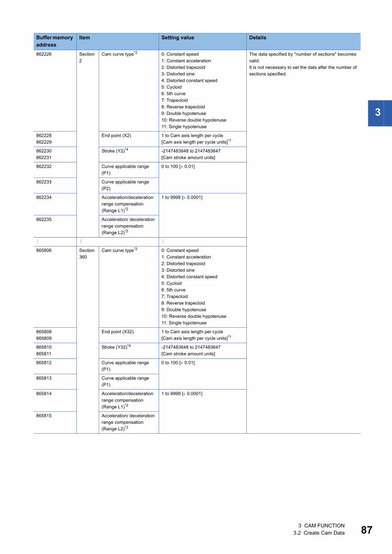
3
862226 Section
2
Cam curve type*2 0: Constant speed
1: Constant acceleration
2: Distorted trapezoid
3: Distorted sine
4: Distorted constant speed
5: Cycloid
6: 5th curve
7: Trapecloid
8: Reverse trapecloid
9: Double hypotenuse
10: Reverse double hypotenuse
11: Single hypotenuse
The data specified by "number of sections" becomes
valid.
It is not necessary to set the data after the number of
sections specified.
862228
862229
End point (X2) 1 to Cam axis length per cycle
[Cam axis length per cycle units]*1
862230
862231
Stroke (Y2)*4 -2147483648 to 2147483647
[Cam stroke amount units]
862232 Curve applicable range
(P1)
0 to 100 [ 0.01]
862233 Curve applicable range
(P2)
862234 Acceleration/deceleration
range compensation
(Range L1)*2
1 to 9999 [ 0.0001]
862235 Acceleration/ deceleration
range compensation
(Range L2)*2
865806 Section
360
Cam curve type*2 0: Constant speed
1: Constant acceleration
2: Distorted trapezoid
3: Distorted sine
4: Distorted constant speed
5: Cycloid
6: 5th curve
7: Trapecloid
8: Reverse trapecloid
9: Double hypotenuse
10: Reverse double hypotenuse
11: Single hypotenuse
865808
865809
End point (X32) 1 to Cam axis length per cycle
[Cam axis length per cycle units]*1
865810
865811
Stroke (Y32)*4 -2147483648 to 2147483647
[Cam stroke amount units]
865812 Curve applicable range
(P1)
0 to 100 [ 0.01]
865813 Curve applicable range
(P1)
865814 Acceleration/deceleration
range compensation
(Range L1)*2
1 to 9999 [ 0.0001]
865815 Acceleration/ deceleration
range compensation
(Range L2)*2
Buffer memory address
Item Setting value Details
3 CAM FUNCTION3.2 Create Cam Data 87

88
*1 If setting is outside range, the cam axis length per cycle will be set as the final end point of the section settings.*2 Refer to the following for the shapes of each cam type and ranges/default value for L1 and L2. Set "0" for the types of cam curves that
do not use L1 and L2.[Cam curve list]
*3 The set value is only used for cam data generation. Control is performed by the output axis parameter "[Pr.439] Cam axis length per cycle" and "[Pr.441] Cam stroke amount".
*4 When the cam stroke amount units is a unit other than "%", set the stroke amount so that "Stroke (Yn) / cam stroke amount" is inside the range of "-2.147483648 to 2.147483647".
• Set data for the number of sections specified. It is not necessary to set the data after the number of sections
specified.
• Set the end point data in ascending order.
• Various cam patterns are created by the setting of the stroke and cam data of each section. If the amount of
change in stroke is large, it may cause a servo error in the servo amplifier including overspeed, command
frequency error etc. When creating cam, confirm the cam operation in amplifier-less operation.
• Cam data will end at the section where the end point is exceeds the cam axis length per cycle set by the
auto-generation data.
3 CAM FUNCTION3.2 Create Cam Data
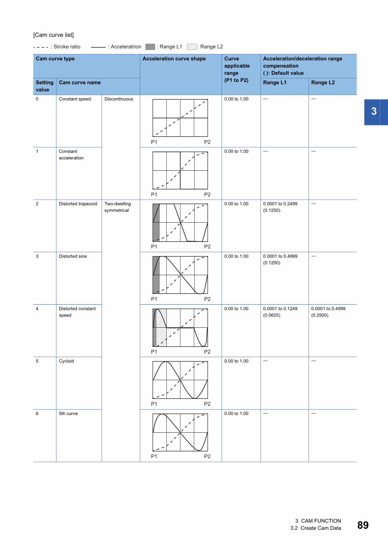
3
[Cam curve list]
Cam curve type Acceleration curve shape Curve applicable range(P1 to P2)
Acceleration/deceleration range compensation( ): Default value
Setting value
Cam curve name Range L1 Range L2
0 Constant speed Discontinuous 0.00 to 1.00
1 Constant
acceleration
0.00 to 1.00
2 Distorted trapezoid Two-dwelling
symmetrical
0.00 to 1.00 0.0001 to 0.2499
(0.1250)
3 Distorted sine 0.00 to 1.00 0.0001 to 0.4999
(0.1250)
4 Distorted constant
speed
0.00 to 1.00 0.0001 to 0.1249
(0.0625)
0.0001 to 0.4999
(0.2500)
5 Cycloid 0.00 to 1.00
6 5th curve 0.00 to 1.00
: Range L1 : Range L2: Stroke ratio : Acceleratrion
P1 P2
P1 P2
P1 P2
P1 P2
P1 P2
P1 P2
P1 P2
3 CAM FUNCTION3.2 Create Cam Data 89

90
7 Trapecloid Two-dwelling
asymmetrical
0.00 to 1.00 0.0001 to 0.2499
(0.1250)
8 Reverse trapecloid 0.00 to 1.00 0.0001 to 0.2499
(0.1250)
9 Double hypotenuse One-dwelling 0.00 to 1.00
10 Reverse double
hypotenuse
0.00 to 1.00
11 Single hypotenuse Non-dwelling
curve
0.00 to 1.00
Cam curve type Acceleration curve shape Curve applicable range(P1 to P2)
Acceleration/deceleration range compensation( ): Default value
Setting value
Cam curve name Range L1 Range L2
P1 P2
P1 P2
P1 P2
P1 P2
P1 P2
3 CAM FUNCTION3.2 Create Cam Data
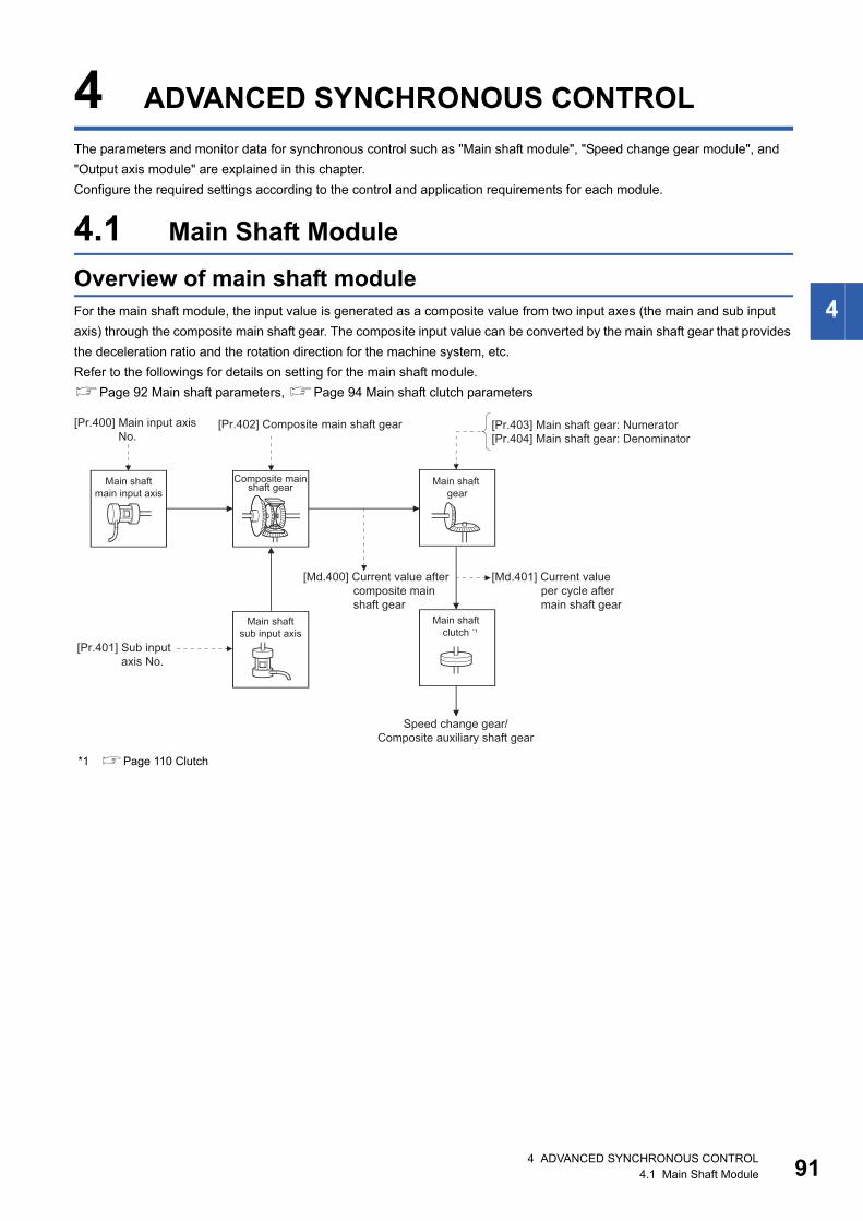
4
4 ADVANCED SYNCHRONOUS CONTROL
The parameters and monitor data for synchronous control such as "Main shaft module", "Speed change gear module", and
"Output axis module" are explained in this chapter.
Configure the required settings according to the control and application requirements for each module.
4.1 Main Shaft Module
Overview of main shaft moduleFor the main shaft module, the input value is generated as a composite value from two input axes (the main and sub input
axis) through the composite main shaft gear. The composite input value can be converted by the main shaft gear that provides
the deceleration ratio and the rotation direction for the machine system, etc.
Refer to the followings for details on setting for the main shaft module.
Page 92 Main shaft parameters, Page 94 Main shaft clutch parameters
*1 Page 110 Clutch
Composite mainshaft gearMain shaft
main input axisMain shaft
gear
Main shaftsub input axis
Speed change gear/Composite auxiliary shaft gear
Main shaftclutch *1
[Pr.400] Main input axis No.
[Pr.402] Composite main shaft gear
[Pr.401] Sub inputaxis No.
[Md.400] Current value after composite main shaft gear
[Pr.403] Main shaft gear: Numerator[Pr.404] Main shaft gear: Denominator
[Md.401] Current valueper cycle aftermain shaft gear
4 ADVANCED SYNCHRONOUS CONTROL4.1 Main Shaft Module 91

92
Main shaft parametersn: Axis No. - 1 (n: Axis No. - 17 for axis 17 to axis 32)
*1 The range from axis 1 to 2 is valid in the 2-axis module, from axis 1 to 4 is valid in the 4-axis module, from axis 1 to 8 is valid in the 8-axis module, from axis 1 to 16 is valid in the 16-axis module, and from axis 1 to 32 is valid in the 32-axis module.
[Pr.400] Main input axis No., [Pr.401] Sub input axis No.Set the main input axis No. and the sub input axis No. for the main shaft.
*1 The range from axis 1 to 2 is valid in the 2-axis module, from axis 1 to 4 is valid in the 4-axis module, from axis 1 to 8 is valid in the 8-axis module, from axis 1 to 16 is valid in the 16-axis module, and from axis 1 to 32 is valid in the 32-axis module.
Setting item Setting details Setting value Default value
Buffer memory address
Axis 1 to axis 16
Axis 17 to axis 32
[Pr.400]
Main input axis
No.
• Set the input axis No. on the main input
side for the main shaft.
Fetch cycle: At start of synchronous control
■Set in decimal.
0: Invalid
1 to 32: Servo input axis*1
801 to 804: Synchronous encoder axis
[RD77MS]
801 to 832: Synchronous encoder axis*1
[RD77GF]
0 36400+200n 1036400+200n
[Pr.401]
Sub input axis No.
• Set the input axis No. on the sub input side
for the main shaft.
Fetch cycle: At start of synchronous control
■Set in decimal.
0: Invalid
1 to 32: Servo input axis*1
801 to 804: Synchronous encoder axis
[RD77MS]
801 to 832: Synchronous encoder axis*1
[RD77GF]
0 36401+200n 1036401+200n
[Pr.402]
Composite main
shaft gear
• Select the composite method for input
values from the main input axis and sub
input axis.
Fetch cycle: Operation cycle
■Set in hexadecimal. 0001H 36402+200n 1036402+200n
[Pr.403]
Main shaft gear:
Numerator
• Set the numerator for the main shaft gear.
Fetch cycle: At start of synchronous control
■Set in decimal.
-2147483648 to 2147483647
1 36404+200n
36405+200n
1036404+200n
1036405+200n
[Pr.404]
Main shaft gear:
Denominator
• Set the denominator for the main shaft
gear.
Fetch cycle: At start of synchronous control
■Set in decimal.
1 to 2147483647
1 36406+200n
36407+200n
1036406+200n
1036407+200n
Setting value Details
0: Invalid The input value is always 0.
1 to 32: Servo input axis*1 Set the servo input axis (axis 1 to axis 32). When the servo input axis is not set in the system setting, the input value
is always 0.
If the No. is set to the same value as the output axis, the following errors occur and synchronous control cannot be
started.
• Outside main input axis No. range (error code: 1BE0H)
• Outside sub input axis No. range (error code: 1BE1H)
801 to 804: Synchronous encoder axis
[RD77MS]
801 to 832: Synchronous encoder axis*1
[RD77GF]
Set the synchronous encoder axis (axis 1 to axis 4 [RD77MS], axis 1 to axis 32 [RD77GF]). When the synchronous
encoder axis is invalid, the input value is always 0.
H _ _ _ _Main input method
0: No input1: Input +2: Input -
Sub input method0: No input1: Input +2: Input -
4 ADVANCED SYNCHRONOUS CONTROL4.1 Main Shaft Module

4
[Pr.402] Composite main shaft gearSet the composite method for input values from the main and sub input axes. The setting values for each axis are shown as
follows.
Operation assumes "0: No input" if the value is set out of the range from 0 to 2.
The composite method for the composite main shaft gear can be changed during synchronous control. It is
used as a clutch to switch input values between the main and the sub input axes.
[Pr.403] Main shaft gear: Numerator, [Pr.404] Main shaft gear: DenominatorSet the numerator and the denominator for the main shaft gear to convert the input value. The input value is converted as
follows.
The input value direction can be reversed by setting a negative value in the numerator of the main shaft gear.
Set the denominator of the main shaft gear to a value within the range from 1 to 2147483647.
Ex.
Convert the cam axis per cycle to be controlled in intervals of 0.1 mm (0.00394 inch). The cam axis synchronizes with a
conveyer that moves 100 mm (3.937 inch) for every (360.00000 degree) of the main shaft.
"[Pr.403] Main shaft gear: Numerator": 1000 [ 0.1 mm]
"[Pr.404] Main shaft gear: Denominator": 36000000 [ 10-5 degree]
Setting value Details
0: No input The input value from the input axis is calculated as 0.
1: Input+ The input value from the input axis is calculated as it is.
2: Input- The input value from the input axis is calculated with its opposite sign.
Input value after conversion[Pr.403] Main shaft gear: Numerator[Pr.404] Main shaft gear: Denominator= Input value before conversion ×
4 ADVANCED SYNCHRONOUS CONTROL4.1 Main Shaft Module 93

94
Main shaft clutch parametersn: Axis No. - 1 (n: Axis No. - 17 for axis 17 to axis 32)
Setting item Setting details Setting value Default value
Buffer memory address
Axis 1 to axis 16
Axis 17 to axis 32
[Pr.405]
Main shaft clutch
control setting
• Set the control method for the
clutch.
Fetch cycle: Operation cycle
■Set in hexadecimal. 0000H 36408+200n 1036408+200n
[Pr.406]
Main shaft clutch
reference address
setting
• Set the reference address for the
clutch.
Fetch cycle: At start of synchronous
control
■Set in decimal.
0: Current value after composite main shaft
gear
1: Current value per cycle after main shaft gear
0 36409+200n 1036409+200n
[Pr.407]
Main shaft clutch ON
address
• Set the clutch ON address for
address mode. (This setting is
invalid except during address
mode.)
• If the address is out of the range
from 0 to (Cam axis length per
cycle - 1), the address is
converted to a value within range.
Fetch cycle: Operation cycle
■Set in decimal.
-2147483648 to 2147483647
[Main input axis position units*2, or cam axis
cycle units*3]
0 36410+200n
36411+200n
1036410+200n
1036411+200n
[Pr.408]
Movement amount
before main shaft
clutch ON
• Set the movement amount
between the clutch ON condition
completing and the clutch closing.
• Set a positive value when the
reference address is increasing,
and a negative value when it is
decreasing.
Fetch cycle: At completing clutch ON
condition
■Set in decimal.
-2147483648 to 2147483647
[Main input axis position units*2, or cam axis
cycle units*3]
0 36412+200n
36413+200n
1036412+200n
1036413+200n
H _ _ _ _ON control mode0: No clutch1: Clutch command ON/OFF2: Clutch command leading edge3: Clutch command trailing edge4: Address mode5: High speed input request [RD77MS]6: Main shaft clutch control request ON/OFF [RD77GF]7: Main shaft clutch control request leading edge [RD77GF]8: Main shaft clutch control request trailing edge [RD77GF]
OFF control mode0: OFF control invalid1: One-shot OFF2: Clutch command leading edge3: Clutch command trailing edge4: Address mode5: High speed input request [RD77MS]7: Main shaft clutch control request leading edge [RD77GF]8: Main shaft clutch control request trailing edge [RD77GF]
High speed input request signal0 to F: High speed input request
signal from axis 1 toaxis 16*1 [RD77MS]
4 ADVANCED SYNCHRONOUS CONTROL4.1 Main Shaft Module

4
*1 The range from axis 1 to 2 is valid in the 2-axis module, from axis 1 to 4 is valid in the 4-axis module, from axis 1 to 8 is valid in the 8-axis module, and from 1 to 16 is valid in the 16-axis module.
*2 Main input axis position units (Page 28 INPUT AXIS MODULE)*3 Cam axis cycle units (Page 126 Units for the output axis)
[Pr.409]
Main shaft clutch
OFF address
• Set the clutch OFF address for the
address mode. (This setting is
invalid except during address
mode.)
• If the address is out of the range
from 0 to (Cam axis length per
cycle - 1), the address is
converted to a value within range.
Fetch cycle: Operation cycle
■Set in decimal.
-2147483648 to 2147483647
[Main input axis position units*2, or cam axis
cycle units*3]
0 36414+200n
36415+200n
1036414+200n
1036415+200n
[Pr.410]
Movement amount
before main shaft
clutch OFF
• Set the movement amount
between the clutch OFF condition
completing and the clutch
opening.
• Set a positive value when the
reference address is increasing,
and a negative value when it is
decreasing.
Fetch cycle: At completing clutch
OFF condition
■Set in decimal.
-2147483648 to 2147483647
[Main input axis position units*2, or cam axis
cycle units*3]
0 36416+200n
36417+200n
1036416+200n
1036417+200n
[Pr.411]
Main shaft clutch
smoothing method
• Set the clutch smoothing method.
Fetch cycle: At start of synchronous
control
■Set in decimal.
0: Direct
1: Time constant method (Exponent)
2: Time constant method (Linear)
3: Slippage method (Exponent)
4: Slippage method (Linear)
5: Slippage method (Linear: Input value follow
up)
0 36418+200n 1036418+200n
[Pr.412]
Main shaft clutch
smoothing time
constant
• For smoothing with a time
constant method, set the
smoothing time constant.
Fetch cycle: At start of synchronous
control
■Set in decimal.
0 to 5000 [ms]
0 36419+200n 1036419+200n
[Pr.413]
Slippage amount at
main shaft clutch ON
• For smoothing with a slippage
method, set the slippage amount
at clutch ON.
Fetch cycle: At turning clutch ON
■Set in decimal.
0 to 2147483647
[Main input axis position units*2, or cam axis
cycle units*3]
0 36420+200n
36421+200n
1036420+200n
1036421+200n
[Pr.414]
Slippage amount at
main shaft clutch
OFF
• For smoothing with a slippage
method, set the slippage amount
at clutch OFF.
Fetch cycle: At turning clutch OFF
■Set in decimal.
0 to 2147483647
[Main input axis position units*2, or cam axis
cycle units*3]
0 36422+200n
36423+200n
1036422+200n
1036423+200n
Setting item Setting details Setting value Default value
Buffer memory address
Axis 1 to axis 16
Axis 17 to axis 32
4 ADVANCED SYNCHRONOUS CONTROL4.1 Main Shaft Module 95

96
[Pr.405] Main shaft clutch control settingSet the ON and OFF control methods separately for the main shaft clutch.
The clutch control setting can be changed during synchronous control, however, the setting "No clutch" (Direct coupled
operation) cannot be selected during synchronous control after already selecting another setting.
Refer to the following for operation details on the clutch control.
Page 110 Control method for clutch
■ON control mode
Other clutch parameters are not applicable during direct coupled operation by setting "0: No clutch". "[Cd.402]
Main shaft clutch forced OFF command" and the change of the clutch control setting are ignored during direct
coupled operation.
■OFF control mode
Setting value Details
0: No clutch (Direct coupled
operation)
Execute direct coupled operation without clutch control.
1: Clutch command ON/OFF The clutch is turned ON/OFF by the operation of "[Cd.400] Main shaft clutch command" ON/OFF. (Setting in the OFF
control mode are not applicable in this mode.)
2: Clutch command leading edge The clutch is turned ON when "[Cd.400] Main shaft clutch command" passes the leading edge (from OFF to ON).
3: Clutch command trailing edge The clutch is turned ON when "[Cd.400] Main shaft clutch command" passes the trailing edge (from ON to OFF).
4: Address mode The clutch is turned ON when the reference address (the current value after composite main shaft gear or the current
value per cycle after main shaft gear) reaches "[Pr.407] Main shaft clutch ON address".
The movement amount after passing through the ON address is calculated as the output movement amount of the clutch
based on the reference address passing through, thereby controlling the clutch with an accurate movement amount.
5: High speed input request
[RD77MS]
The clutch is turned ON when the high speed input request [DI] turns ON.
6: Main shaft clutch control request
ON/OFF
[RD77GF]
The clutch is turned ON/OFF by ON/OFF operation of the link device assigned to the main shaft clutch control request
by the link device external signal assignment function. (Setting in the OFF control mode are not applicable in this mode.)
7: Main shaft clutch control request
leading edge
[RD77GF]
The clutch is turned ON when the link device assigned to the main shaft clutch control request by the link device external
signal assignment function passes the leading edge (from OFF to ON).
8: Main shaft clutch control request
trailing edge
[RD77GF]
The clutch is turned ON when the link device assigned to the main shaft clutch control request by the link device external
signal assignment function passes the trailing edge (from ON to OFF).
Setting value Details
0: OFF control invalid Clutch OFF control is not used. This setting is applicable only for execution with clutch ON control.
1: One-shot OFF The clutch is turned OFF after moving the distance "[Pr.410] Movement amount before main shaft clutch OFF" (One-
shot operation) after the clutch command turns ON.
If "[Pr.410] Movement amount before main shaft clutch OFF" is 0, "[Md.420] Main shaft clutch ON/OFF status" does not
turn ON in order to turn back OFF immediately.
2: Clutch command leading edge The clutch is turned OFF when "[Cd.400] Main shaft clutch command" passes the leading edge (from OFF to ON).
3: Clutch command trailing edge The clutch is turned OFF when "[Cd.400] Main shaft clutch command" passes the trailing edge (from ON to OFF).
4: Address mode The clutch is turned OFF when the reference address (the current value after composite main shaft gear or the current
value per cycle after main shaft gear) reaches "[Pr.409] Main shaft clutch OFF address".
The movement amount before passing through the OFF address is calculated as the output movement amount of the
clutch based on the reference address passing through, thereby controlling the clutch with an accurate movement
amount.
5: High speed input request
[RD77MS]
The clutch is turned OFF when the high speed input request [DI] turns ON.
7: Main shaft clutch control request
leading edge
[RD77GF]
The clutch is turned OFF when the link device assigned to the main shaft clutch control request by the link device
external signal assignment function passes the leading edge (from OFF to ON).
8: Main shaft clutch control request
trailing edge
[RD77GF]
The clutch is turned OFF when the link device assigned to the main shaft clutch control request by the link device
external signal assignment function passes the trailing edge (from ON to OFF).
4 ADVANCED SYNCHRONOUS CONTROL4.1 Main Shaft Module
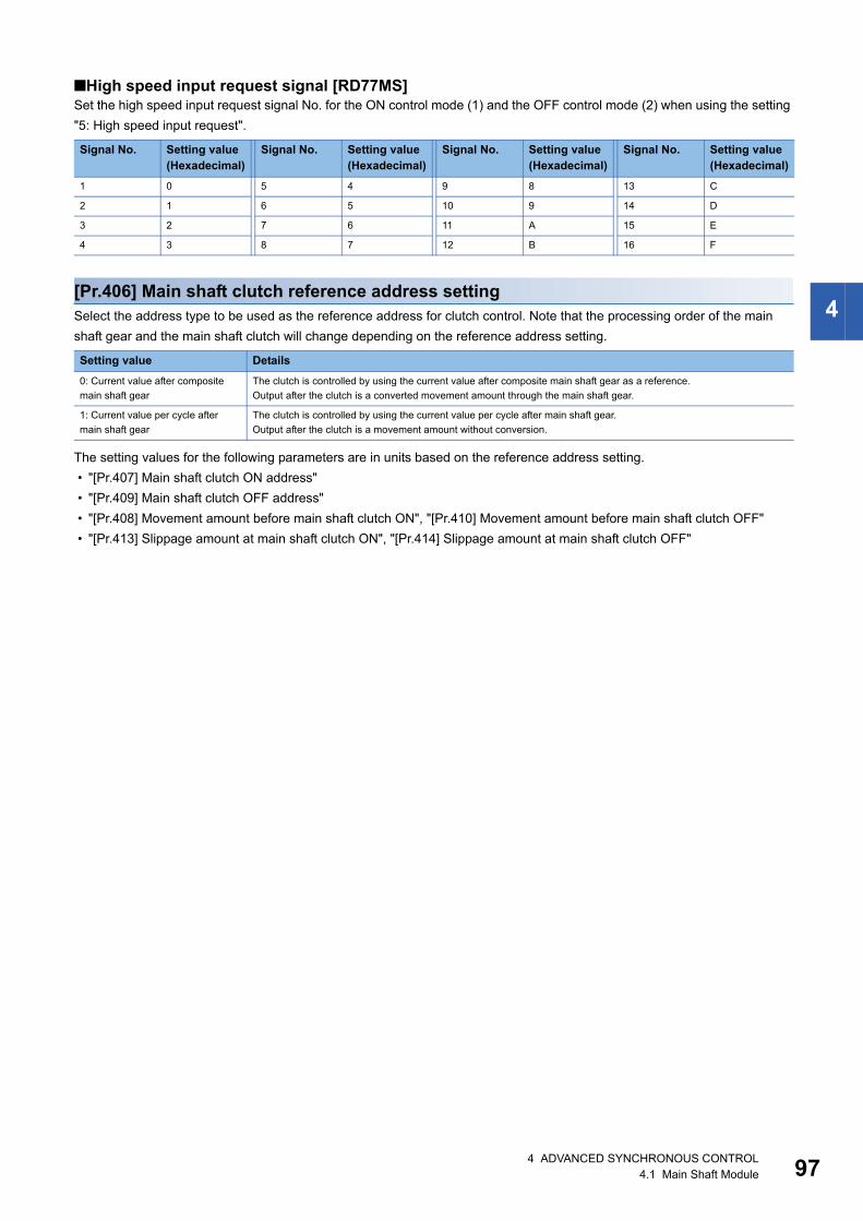
4
■High speed input request signal [RD77MS]Set the high speed input request signal No. for the ON control mode (1) and the OFF control mode (2) when using the setting
"5: High speed input request".
[Pr.406] Main shaft clutch reference address settingSelect the address type to be used as the reference address for clutch control. Note that the processing order of the main
shaft gear and the main shaft clutch will change depending on the reference address setting.
The setting values for the following parameters are in units based on the reference address setting.
• "[Pr.407] Main shaft clutch ON address"
• "[Pr.409] Main shaft clutch OFF address"
• "[Pr.408] Movement amount before main shaft clutch ON", "[Pr.410] Movement amount before main shaft clutch OFF"
• "[Pr.413] Slippage amount at main shaft clutch ON", "[Pr.414] Slippage amount at main shaft clutch OFF"
Signal No. Setting value(Hexadecimal)
Signal No. Setting value(Hexadecimal)
Signal No. Setting value(Hexadecimal)
Signal No. Setting value(Hexadecimal)
1 0 5 4 9 8 13 C
2 1 6 5 10 9 14 D
3 2 7 6 11 A 15 E
4 3 8 7 12 B 16 F
Setting value Details
0: Current value after composite
main shaft gear
The clutch is controlled by using the current value after composite main shaft gear as a reference.
Output after the clutch is a converted movement amount through the main shaft gear.
1: Current value per cycle after
main shaft gear
The clutch is controlled by using the current value per cycle after main shaft gear.
Output after the clutch is a movement amount without conversion.
4 ADVANCED SYNCHRONOUS CONTROL4.1 Main Shaft Module 97

98
[Pr.407] Main shaft clutch ON addressSet the clutch ON address when address mode is configured for the ON control mode of the main shaft clutch.
When the reference address is the current value per cycle after main shaft gear, the setting address is converted for control
within the range from 0 to (Cam axis length per cycle - 1).
Ex.
Cam axis length per cycle: 20000 pulses
The ON address is controlled as 19000 pulses when the setting value is "-1000".
[Pr.408] Movement amount before main shaft clutch ONSet the movement amount of the reference address with a signed value between the clutch ON condition completing and the
clutch closing.
[Pr.409] Main shaft clutch OFF addressSet the clutch OFF address when address mode is configured for the OFF control mode of the main shaft clutch.
When the reference address is the current value per cycle after main shaft gear, the setting address is converted for control
within the range from 0 to (Cam axis length per cycle - 1).
Ex.
Cam axis length per cycle: 20000 pulses
The OFF address is controlled as 60 pulses when the setting value is "40060".
Setting value Details
1 to 2147483647 (Positive value) Used when the reference address is increasing in direction.
0 No movement amount (The clutch is immediately turned ON with the clutch ON condition completing.)
-2147483648 to -1 (Negative value) Used when the reference address is decreasing in direction.
t
t
[Pr.408] Movement amount beforemain shaft clutch ON (Positive value)
Movement amount after clutch
[Md.420] Main shaft clutchON/OFF status
[Md.401] Current value percycle after main shaft gear
[Md.400] Current value aftercomposite main shaft gearor
Clutch ON condition is completed(Example: [Cd.400] Main shaft clutch command ON)
4 ADVANCED SYNCHRONOUS CONTROL4.1 Main Shaft Module
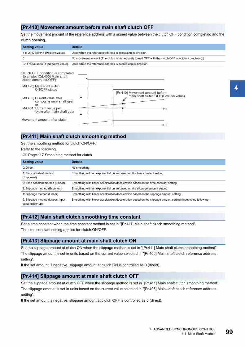
4
[Pr.410] Movement amount before main shaft clutch OFFSet the movement amount of the reference address with a signed value between the clutch OFF condition completing and the
clutch opening.
[Pr.411] Main shaft clutch smoothing methodSet the smoothing method for clutch ON/OFF.
Refer to the following.
Page 117 Smoothing method for clutch
[Pr.412] Main shaft clutch smoothing time constantSet a time constant when the time constant method is set in "[Pr.411] Main shaft clutch smoothing method".
The time constant setting applies for clutch ON/OFF.
[Pr.413] Slippage amount at main shaft clutch ONSet the slippage amount at clutch ON when the slippage method is set in "[Pr.411] Main shaft clutch smoothing method".
The slippage amount is set in units based on the current value selected in "[Pr.406] Main shaft clutch reference address
setting".
If the set amount is negative, slippage amount at clutch ON is controlled as 0 (direct).
[Pr.414] Slippage amount at main shaft clutch OFFSet the slippage amount at clutch OFF when the slippage method is set in "[Pr.411] Main shaft clutch smoothing method".
The slippage amount is set in units based on the current value selected in "[Pr.406] Main shaft clutch reference address
setting".
If the set amount is negative, slippage amount at clutch OFF is controlled as 0 (direct).
Setting value Details
1 to 2147483647 (Positive value) Used when the reference address is increasing in direction.
0 No movement amount (The clutch is immediately turned OFF with the clutch OFF condition completing.)
-2147483648 to -1 (Negative value) Used when the reference address is decreasing in direction.
Setting value Details
0: Direct No smoothing
1: Time constant method
(Exponent)
Smoothing with an exponential curve based on the time constant setting.
2: Time constant method (Linear) Smoothing with linear acceleration/deceleration based on the time constant setting.
3: Slippage method (Exponent) Smoothing with an exponential curve based on the slippage amount setting.
4: Slippage method (Linear) Smoothing with linear acceleration/deceleration based on the slippage amount setting.
5: Slippage method (Linear: Input
value follow up)
Smoothing with linear acceleration/deceleration based on the slippage amount setting (input value follow up).
t
t
[Pr.410] Movement amount beforemain shaft clutch OFF (Positive value)
Movement amount after clutch
[Md.420] Main shaft clutchON/OFF status
Clutch OFF condition is completed(Example: [Cd.400] Main shaft clutch command OFF)
[Md.401] Current value percycle after main shaft gear
[Md.400] Current value aftercomposite main shaft gearor
4 ADVANCED SYNCHRONOUS CONTROL4.1 Main Shaft Module 99

10
Main shaft clutch control datan: Axis No. - 1 (n: Axis No. - 17 for axis 17 to axis 32)
[Cd.400] Main shaft clutch commandSet ON/OFF for the main shaft clutch command. This command is used when the clutch ON control mode is "1: Clutch
command ON/OFF", "2: Clutch command leading edge" or "3: Clutch command trailing edge" and the clutch OFF control
mode is "2: Clutch command leading edge" or "3: Clutch command trailing edge".
Status is considered as clutch command OFF just before starting synchronous control. If synchronous control is started while
the clutch command is ON, the condition is established just after starting synchronous control, by setting "2: Clutch command
leading edge". The condition is not established just after starting, by setting "3: Clutch command trailing edge".
[Cd.401] Main shaft clutch control invalid commandThe main shaft clutch control is invalid if "1" is set. The previous clutch ON/OFF status remains before clutch control becomes
invalid.
Clutch control will not become invalid during the movement before clutch ON and clutch OFF. Instead, clutch control will
become invalid after movement is completed.
[Cd.402] Main shaft clutch forced OFF commandSet "1" to force the clutch OFF. The output value from the clutch becomes 0 immediately, even during clutch smoothing. The
slippage (accumulative) amount is set to 0 if smoothing with a slippage method.
Reset to "0" to restart the clutch control from the clutch OFF status after using the clutch forced OFF command.
Setting item Setting details Setting value Default value
Buffer memory address
Axis 1 to axis 16
Axis 17 to axis 32
[Cd.400]
Main shaft clutch
command
• Set the clutch command ON/OFF.
Fetch cycle: Operation cycle
■Set in decimal.
0: Main shaft clutch
command OFF
1: Main shaft clutch
command ON
0 44080+20n 1044080+20n
[Cd.401]
Main shaft clutch
control invalid
command
• Set "1" to disable the clutch control temporarily.
Fetch cycle: Operation cycle
■Set in decimal.
0: Main shaft clutch control
valid
1: Main shaft clutch control
invalid
0 44081+20n 1044081+20n
[Cd.402]
Main shaft clutch
forced OFF
command
• Set "1" to force the clutch OFF.
Fetch cycle: Operation cycle
■Set in decimal.
0: Main shaft clutch normal
control
1: Main shaft clutch forced
OFF
0 44082+20n 1044082+20n
04 ADVANCED SYNCHRONOUS CONTROL4.1 Main Shaft Module
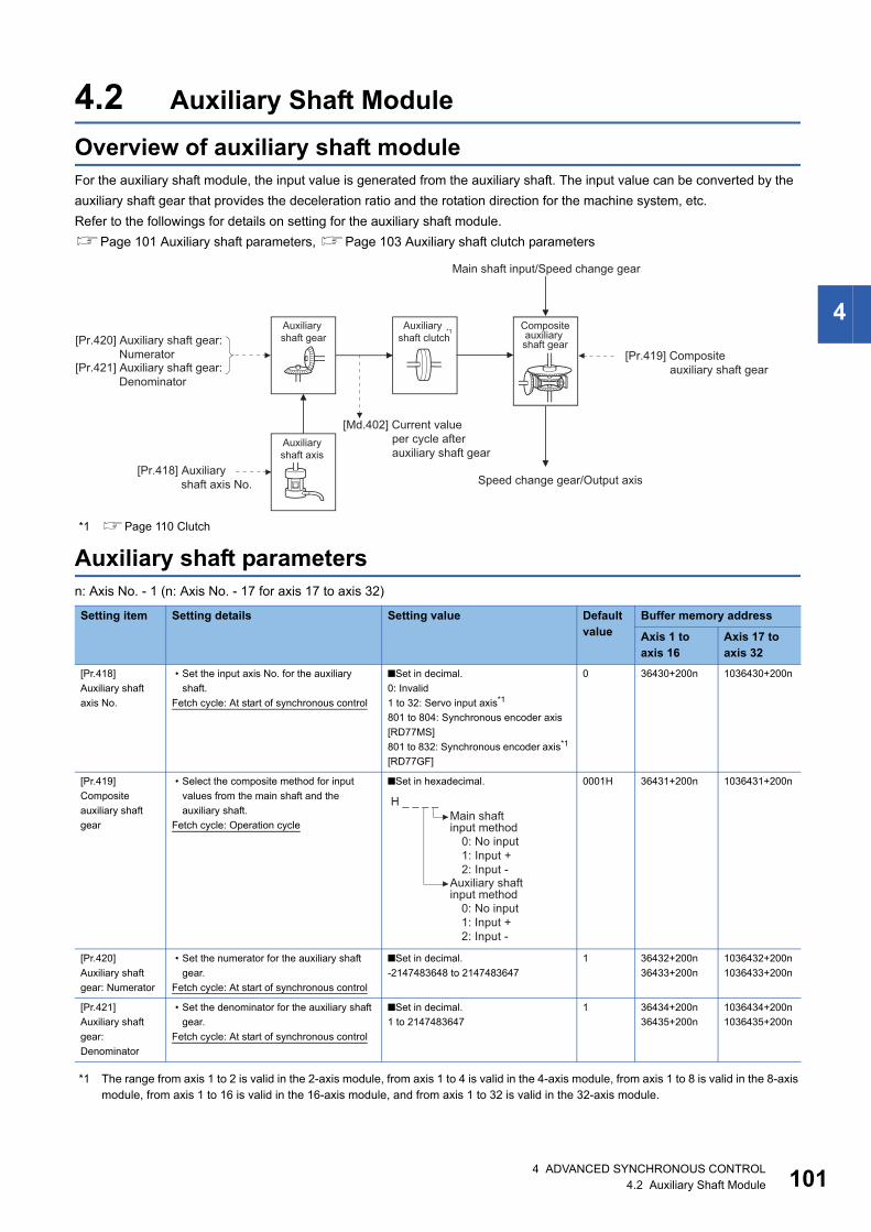
4
4.2 Auxiliary Shaft Module
Overview of auxiliary shaft moduleFor the auxiliary shaft module, the input value is generated from the auxiliary shaft. The input value can be converted by the
auxiliary shaft gear that provides the deceleration ratio and the rotation direction for the machine system, etc.
Refer to the followings for details on setting for the auxiliary shaft module.
Page 101 Auxiliary shaft parameters, Page 103 Auxiliary shaft clutch parameters
*1 Page 110 Clutch
Auxiliary shaft parametersn: Axis No. - 1 (n: Axis No. - 17 for axis 17 to axis 32)
*1 The range from axis 1 to 2 is valid in the 2-axis module, from axis 1 to 4 is valid in the 4-axis module, from axis 1 to 8 is valid in the 8-axis module, from axis 1 to 16 is valid in the 16-axis module, and from axis 1 to 32 is valid in the 32-axis module.
Setting item Setting details Setting value Default value
Buffer memory address
Axis 1 to axis 16
Axis 17 to axis 32
[Pr.418]
Auxiliary shaft
axis No.
• Set the input axis No. for the auxiliary
shaft.
Fetch cycle: At start of synchronous control
■Set in decimal.
0: Invalid
1 to 32: Servo input axis*1
801 to 804: Synchronous encoder axis
[RD77MS]
801 to 832: Synchronous encoder axis*1
[RD77GF]
0 36430+200n 1036430+200n
[Pr.419]
Composite
auxiliary shaft
gear
• Select the composite method for input
values from the main shaft and the
auxiliary shaft.
Fetch cycle: Operation cycle
■Set in hexadecimal. 0001H 36431+200n 1036431+200n
[Pr.420]
Auxiliary shaft
gear: Numerator
• Set the numerator for the auxiliary shaft
gear.
Fetch cycle: At start of synchronous control
■Set in decimal.
-2147483648 to 2147483647
1 36432+200n
36433+200n
1036432+200n
1036433+200n
[Pr.421]
Auxiliary shaft
gear:
Denominator
• Set the denominator for the auxiliary shaft
gear.
Fetch cycle: At start of synchronous control
■Set in decimal.
1 to 2147483647
1 36434+200n
36435+200n
1036434+200n
1036435+200n
[Pr.418] Auxiliaryshaft axis No.
[Pr.420] Auxiliary shaft gear:Numerator
Auxiliary shaft gear
Auxiliaryshaft axis
Compositeauxiliary shaft gear
Speed change gear/Output axis
[Pr.421] Auxiliary shaft gear:Denominator
Auxiliary shaft clutch
*1
Main shaft input/Speed change gear
[Md.402] Current valueper cycle afterauxiliary shaft gear
[Pr.419] Compositeauxiliary shaft gear
H _ _ _ _
0: No input1: Input +2: Input -
Main shaft input method
0: No input1: Input +2: Input -
Auxiliary shaft input method
4 ADVANCED SYNCHRONOUS CONTROL4.2 Auxiliary Shaft Module 101
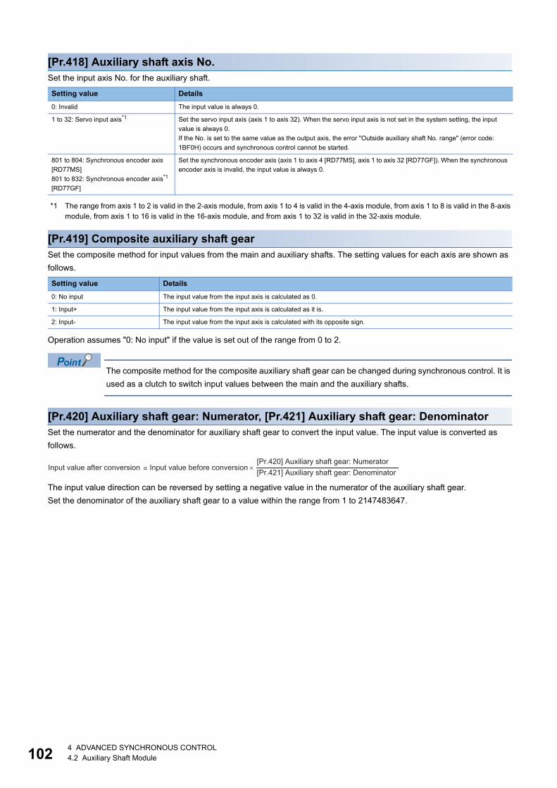
10
[Pr.418] Auxiliary shaft axis No.Set the input axis No. for the auxiliary shaft.
*1 The range from axis 1 to 2 is valid in the 2-axis module, from axis 1 to 4 is valid in the 4-axis module, from axis 1 to 8 is valid in the 8-axis module, from axis 1 to 16 is valid in the 16-axis module, and from axis 1 to 32 is valid in the 32-axis module.
[Pr.419] Composite auxiliary shaft gearSet the composite method for input values from the main and auxiliary shafts. The setting values for each axis are shown as
follows.
Operation assumes "0: No input" if the value is set out of the range from 0 to 2.
The composite method for the composite auxiliary shaft gear can be changed during synchronous control. It is
used as a clutch to switch input values between the main and the auxiliary shafts.
[Pr.420] Auxiliary shaft gear: Numerator, [Pr.421] Auxiliary shaft gear: DenominatorSet the numerator and the denominator for auxiliary shaft gear to convert the input value. The input value is converted as
follows.
The input value direction can be reversed by setting a negative value in the numerator of the auxiliary shaft gear.
Set the denominator of the auxiliary shaft gear to a value within the range from 1 to 2147483647.
Setting value Details
0: Invalid The input value is always 0.
1 to 32: Servo input axis*1 Set the servo input axis (axis 1 to axis 32). When the servo input axis is not set in the system setting, the input
value is always 0.
If the No. is set to the same value as the output axis, the error "Outside auxiliary shaft No. range" (error code:
1BF0H) occurs and synchronous control cannot be started.
801 to 804: Synchronous encoder axis
[RD77MS]
801 to 832: Synchronous encoder axis*1
[RD77GF]
Set the synchronous encoder axis (axis 1 to axis 4 [RD77MS], axis 1 to axis 32 [RD77GF]). When the synchronous
encoder axis is invalid, the input value is always 0.
Setting value Details
0: No input The input value from the input axis is calculated as 0.
1: Input+ The input value from the input axis is calculated as it is.
2: Input- The input value from the input axis is calculated with its opposite sign.
[Pr.420] Auxiliary shaft gear: Numerator[Pr.421] Auxiliary shaft gear: Denominator
×Input value before conversion=Input value after conversion
24 ADVANCED SYNCHRONOUS CONTROL4.2 Auxiliary Shaft Module

4
Auxiliary shaft clutch parametersn: Axis No. - 1 (n: Axis No. - 17 for axis 17 to axis 32)
Setting item Setting details Setting value Default value
Buffer memory address
Axis 1 to axis 16
Axis 17 to axis 32
[Pr.422]
Auxiliary shaft
clutch control
setting
• Set the control method for the
clutch.
Fetch cycle: Operation cycle
■Set in hexadecimal. 0000H 36436+200n 1036436+200n
[Pr.423]
Auxiliary shaft
clutch reference
address setting
• Set the reference address for the
clutch.
Fetch cycle: At start of synchronous
control
■Set in decimal.
0: Auxiliary shaft current value
1: Current value per cycle after auxiliary shaft
gear
0 36437+200n 1036437+200n
[Pr.424]
Auxiliary shaft
clutch ON address
• Set the clutch ON address for
address mode. (This setting is
invalid except during address
mode.)
• If the address is out of the range
from 0 to (Cam axis length per
cycle - 1), the address is
converted to a value within range.
Fetch cycle: Operation cycle
■Set in decimal.
-2147483648 to 2147483647
[Auxiliary shaft position units*2, or cam axis
cycle units*3]
0 36438+200n
36439+200n
1036438+200n
1036439+200n
[Pr.425]
Movement amount
before auxiliary
shaft clutch ON
• Set the movement amount
between the clutch ON condition
completing and the clutch closing.
• Set the movement amount
between the clutch ON condition
completing and the clutch closing.
Fetch cycle: At completing clutch ON
condition
■Set in decimal.
-2147483648 to 2147483647
[Auxiliary shaft position units*2, or cam axis
cycle units*3]
0 36440+200n
36441+200n
1036440+200n
1036441+200n
H _ _ _ _ON control mode0: No clutch1: Clutch command ON/OFF2: Clutch command leading edge3: Clutch command trailing edge4: Address mode5: High speed input request [RD77MS]6: Auxiliary shaft clutch control request ON/OFF [RD77GF]7: Auxiliary shaft clutch control request leading edge [RD77GF]8: Auxiliary shaft clutch control request trailing edge [RD77GF]
OFF control mode0: OFF control invalid1: One-shot OFF2: Clutch command leading edge3: Clutch command trailing edge4: Address mode5: High speed input request [RD77MS]7: Auxiliary shaft clutch control request leading edge [RD77GF]8: Auxiliary shaft clutch control request trailing edge [RD77GF]
High speed input request signal0 to F: High speed input request
signal from axis 1 to axis16*1 [RD77MS]
4 ADVANCED SYNCHRONOUS CONTROL4.2 Auxiliary Shaft Module 103

10
*1 The range from axis 1 to 2 is valid in the 2-axis module, from axis 1 to 4 is valid in the 4-axis module, from axis 1 to 8 is valid in the 8-axis module, and from 1 to 16 is valid in the 16-axis module.
*2 Auxiliary shaft position units (Page 28 INPUT AXIS MODULE)*3 Cam axis cycle units (Page 126 Units for the output axis)
[Pr.422] Auxiliary shaft clutch control settingSet the ON and OFF control methods separately for the auxiliary shaft.
The clutch control setting can be changed during synchronous control, however, the setting "No clutch" (Direct coupled
operation) cannot be selected during synchronous control after already selecting another setting.
Refer to the following for operation details on the clutch control.
Page 110 Control method for clutch
[Pr.426]
Auxiliary shaft
clutch OFF
address
• Set the clutch OFF address for the
address mode. (This setting is
invalid except during address
mode.)
• If the address is out of the range
from 0 to (Cam axis length per
cycle - 1), the address is
converted to a value within range.
Fetch cycle: Operation cycle
■Set in decimal.
-2147483648 to 2147483647
[Auxiliary shaft position units*2, or cam axis
cycle units*3]
0 36442+200n
36443+200n
1036442+200n
1036443+200n
[Pr.427]
Movement amount
before auxiliary
shaft clutch OFF
• Set the movement amount
between the clutch OFF condition
completing and the clutch
opening.
• Set a positive value when the
reference address is increasing,
and a negative value when it is
decreasing.
Fetch cycle: At completing clutch
OFF condition
■Set in decimal.
-2147483648 to 2147483647
[Auxiliary shaft position units*2, or cam axis
cycle units*3]
0 36444+200n
36445+200n
1036444+200n
1036445+200n
[Pr.428]
Auxiliary shaft
clutch smoothing
method
• Set the clutch smoothing method.
Fetch cycle: At start of synchronous
control
■Set in decimal.
0: Direct
1: Time constant method (Exponent)
2: Time constant method (Linear)
3: Slippage method (Exponent)
4: Slippage method (Linear)
5: Slippage method (Linear: Input value follow
up)
0 36446+200n 1036446+200n
[Pr.429]
Auxiliary shaft
clutch smoothing
time constant
• For smoothing with a time
constant method, set the
smoothing time constant.
Fetch cycle: At start of synchronous
control
■Set in decimal.
0 to 5000 [ms]
0 36447+200n 1036447+200n
[Pr.430]
Slippage amount at
auxiliary shaft
clutch ON
• For smoothing with a slippage
method, set the slippage amount
at clutch ON.
Fetch cycle: At turning clutch ON
■Set in decimal.
0 to 2147483647
[Auxiliary shaft position units*2, or cam axis
cycle units*3]
0 36448+200n
36449+200n
1036448+200n
1036449+200n
[Pr.431]
Slippage amount at
auxiliary shaft
clutch OFF
• For smoothing with a slippage
method, set the slippage amount
at clutch OFF.
Fetch cycle: At turning clutch OFF
■Set in decimal.
0 to 2147483647
[Auxiliary shaft position units*2, or cam axis
cycle units*3]
0 36450+200n
36451+200n
1036450+200n
1036451+200n
Setting item Setting details Setting value Default value
Buffer memory address
Axis 1 to axis 16
Axis 17 to axis 32
44 ADVANCED SYNCHRONOUS CONTROL4.2 Auxiliary Shaft Module

4
■ON control mode
Other clutch parameters are not applicable during direct coupled operation by setting "0: No clutch". "[Cd.405]
Auxiliary shaft clutch forced OFF command" and the change of the clutch control setting are ignored during
direct coupled operation.
■OFF control mode
Setting value Details
0: No clutch (Direct coupled
operation)
Execute direct coupled operation without clutch control.
1: Clutch command ON/OFF The clutch is turned ON/OFF by the operation of "[Cd.403] Auxiliary shaft clutch command" ON/OFF. (Setting in the
OFF control mode are not applicable in this mode.)
2: Clutch command leading edge The clutch is turned ON when "[Cd.403] Auxiliary shaft clutch command" passes the leading edge (from OFF to ON).
3: Clutch command trailing edge The clutch is turned ON when "[Cd.403] Auxiliary shaft clutch command" passes the trailing edge (from ON to OFF).
4: Address mode The clutch is turned ON when the reference address (the auxiliary shaft current value or the current value per cycle
after auxiliary shaft gear) reaches "[Pr.424] Auxiliary shaft clutch ON address".
The movement amount after passing through the ON address is calculated as the output movement amount of the
clutch based on the reference address passing through, thereby controlling the clutch with an accurate movement
amount.
5: High speed input request
[RD77MS]
The clutch is turned ON when the high speed input request [DI] turns ON.
6: Auxiliary shaft clutch control
request ON/OFF
[RD77GF]
The clutch is turned ON/OFF by ON/OFF operation of the link device assigned to the auxiliary shaft clutch control
request by the link device external signal assignment function. (Setting in the OFF control mode are not applicable in
this mode.)
7: Auxiliary shaft clutch control
request leading edge
[RD77GF]
The clutch is turned ON when the link device assigned to the auxiliary shaft clutch control request by the link device
external signal assignment function passes the leading edge (from OFF to ON).
8: Auxiliary shaft clutch control
request trailing edge
[RD77GF]
The clutch is turned ON when the link device assigned to the auxiliary shaft clutch control request by the link device
external signal assignment function passes the trailing edge (from ON to OFF).
Setting value Details
0: OFF control invalid Clutch OFF control is not used. This setting is applicable only for execution with clutch ON control.
1: One-shot OFF The clutch is turned OFF after moving the distance "[Pr.427] Movement amount before auxiliary shaft clutch OFF"
(One-shot operation) after the clutch command turns ON.
If "[Pr.427] Movement amount before auxiliary shaft clutch OFF" is 0, "[Md.423] Auxiliary shaft clutch ON/OFF status"
does not turn ON in order to turn back OFF immediately.
2: Clutch command leading edge The clutch is turned OFF when "[Cd.403] Auxiliary shaft clutch command" passes the leading edge (from OFF to ON).
3: Clutch command trailing edge The clutch is turned OFF when "[Cd.403] Auxiliary shaft clutch command" passes the trailing edge (from ON to OFF)
4: Address mode The clutch is turned OFF when the reference address (the auxiliary shaft current value or the current value per cycle
after auxiliary shaft gear) reaches "[Pr.426] Auxiliary shaft clutch OFF address".
The movement amount before passing through the OFF address is calculated as the output movement amount of the
clutch based on the reference address passing through, thereby controlling the clutch with an accurate movement
amount.
5: High speed input request
[RD77MS]
The clutch is turned OFF when the high speed input request [DI] turns ON.
7: Auxiliary shaft clutch control
request leading edge
[RD77GF]
The clutch is turned OFF when the link device assigned to the auxiliary shaft clutch control request by the link device
external signal assignment function passes the leading edge (from OFF to ON).
8: Auxiliary shaft clutch control
request trailing edge
[RD77GF]
The clutch is turned OFF when the link device assigned to the auxiliary shaft clutch control request by the link device
external signal assignment function passes the trailing edge (from ON to OFF).
4 ADVANCED SYNCHRONOUS CONTROL4.2 Auxiliary Shaft Module 105

10
■High speed input request signal [RD77MS]Set the high speed input request signal No. for the ON control mode (1) and the OFF control mode (2) when using the setting
"5: High speed input request"
[Pr.423] Auxiliary shaft clutch reference address settingSelect the address type to be used as the reference address for clutch control. Note that the processing order of the auxiliary
shaft gear and the auxiliary shaft clutch will change depending on the reference address setting.
The setting values for the following parameters are in units based on the reference address setting.
• "[Pr.424] Auxiliary shaft clutch ON address"
• "[Pr.426] Auxiliary shaft clutch OFF address"
• "[Pr.425] Movement amount before auxiliary shaft clutch ON", "[Pr.427] Movement amount before auxiliary shaft clutch
OFF"
• "[Pr.430] Slippage amount at auxiliary shaft clutch ON", "[Pr.431] Slippage amount at auxiliary shaft clutch OFF"
Signal No. Setting value(Hexadecimal)
Signal No. Setting value(Hexadecimal)
Signal No. Setting value(Hexadecimal)
Signal No. Setting value(Hexadecimal)
1 0 5 4 9 8 13 C
2 1 6 5 10 9 14 D
3 2 7 6 11 A 15 E
4 3 8 7 12 B 16 F
Setting value Details
0: Auxiliary shaft current value The clutch is controlled by using the current value for the servo input axis/synchronous encoder axis that is set for the
auxiliary shaft.
Output after the clutch is a converted movement amount through the auxiliary shaft gear.
1: Current value per cycle after
auxiliary shaft gear
The clutch is controlled by using the current value per cycle after auxiliary shaft gear.
Output after the clutch is a movement amount without conversion.
64 ADVANCED SYNCHRONOUS CONTROL4.2 Auxiliary Shaft Module

4
[Pr.424] Auxiliary shaft clutch ON addressSet the clutch ON address when address mode is configured for the ON control mode of the auxiliary shaft clutch.
When the reference address is the current value per cycle after auxiliary shaft gear, the setting address is converted for
control within the range from 0 to (Cam axis length per cycle - 1).
Ex.
Cam axis length per cycle: 20000 pulses
The ON address is controlled as 19000 pulses when the setting value is "-1000".
[Pr.425] Movement amount before auxiliary shaft clutch ONSet the movement amount of the reference address with a signed value between the clutch ON condition completing and the
clutch closing.
[Pr.426] Auxiliary shaft clutch OFF addressSet the clutch OFF address when address mode is configured for the OFF control mode of the auxiliary shaft clutch.
When the reference address is the current value per cycle after auxiliary shaft gear, the setting address is converted for
control within the range from 0 to (Cam axis length per cycle - 1).
Ex.
Cam axis length per cycle: 20000 pulses
The OFF address is controlled as 60 pulses when the setting value is "40060".
Setting value Details
1 to 2147483647 (Positive value) Used when the reference address is increasing in direction.
0 No movement amount (The clutch is immediately turned ON with the clutch ON condition completing.)
-2147483648 to -1 (Negative value) Used when the reference address is decreasing in direction.
Movement amount after clutch
[Md.423] Auxiliary shaft clutchON/OFF status
Clutch ON condition is completed(Example: [Cd.403] Auxiliary shaftclutch command ON)
[Md.402] Current value per cycleafter auxiliary shaft gear
Auxiliary shaft current value or
[Pr.425] Movement amount before auxiliary shaft clutch ON (Positive value)
4 ADVANCED SYNCHRONOUS CONTROL4.2 Auxiliary Shaft Module 107
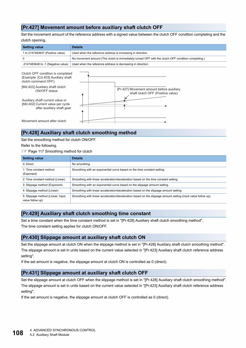
10
[Pr.427] Movement amount before auxiliary shaft clutch OFFSet the movement amount of the reference address with a signed value between the clutch OFF condition completing and the
clutch opening.
[Pr.428] Auxiliary shaft clutch smoothing methodSet the smoothing method for clutch ON/OFF.
Refer to the following.
Page 117 Smoothing method for clutch
[Pr.429] Auxiliary shaft clutch smoothing time constantSet a time constant when the time constant method is set in "[Pr.428] Auxiliary shaft clutch smoothing method".
The time constant setting applies for clutch ON/OFF.
[Pr.430] Slippage amount at auxiliary shaft clutch ONSet the slippage amount at clutch ON when the slippage method is set in "[Pr.428] Auxiliary shaft clutch smoothing method".
The slippage amount is set in units based on the current value selected in "[Pr.423] Auxiliary shaft clutch reference address
setting".
If the set amount is negative, the slippage amount at clutch ON is controlled as 0 (direct).
[Pr.431] Slippage amount at auxiliary shaft clutch OFFSet the slippage amount at clutch OFF when the slippage method is set in "[Pr.428] Auxiliary shaft clutch smoothing method".
The slippage amount is set in units based on the current value selected in "[Pr.423] Auxiliary shaft clutch reference address
setting".
If the set amount is negative, the slippage amount at clutch OFF is controlled as 0 (direct).
Setting value Details
1 to 2147483647 (Positive value) Used when the reference address is increasing in direction.
0 No movement amount (The clutch is immediately turned OFF with the clutch OFF condition completing.)
-2147483648 to -1 (Negative value) Used when the reference address is decreasing in direction.
Setting value Details
0: Direct No smoothing.
1: Time constant method
(Exponent)
Smoothing with an exponential curve based on the time constant setting.
2: Time constant method (Linear) Smoothing with linear acceleration/deceleration based on the time constant setting.
3: Slippage method (Exponent) Smoothing with an exponential curve based on the slippage amount setting.
4: Slippage method (Linear) Smoothing with linear acceleration/deceleration based on the slippage amount setting.
5: Slippage method (Linear: Input
value follow up)
Smoothing with linear acceleration/deceleration based on the slippage amount setting (input value follow up).
Movement amount after clutch
[Md.423] Auxiliary shaft clutchON/OFF status
[Md.402] Current value per cycleafter auxiliary shaft gear
Auxiliary shaft current value or
Clutch OFF condition is completed(Example: [Cd.403] Auxiliary shaftclutch command OFF)
[Pr.427] Movement amount before auxiliary shaft clutch OFF (Positive value)
84 ADVANCED SYNCHRONOUS CONTROL4.2 Auxiliary Shaft Module
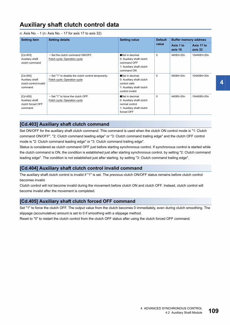
4
Auxiliary shaft clutch control datan: Axis No. - 1 (n: Axis No. - 17 for axis 17 to axis 32)
[Cd.403] Auxiliary shaft clutch commandSet ON/OFF for the auxiliary shaft clutch command. This command is used when the clutch ON control mode is "1: Clutch
command ON/OFF", "2: Clutch command leading edge" or "3: Clutch command trailing edge" and the clutch OFF control
mode is "2: Clutch command leading edge" or "3: Clutch command trailing edge".
Status is considered as clutch command OFF just before starting synchronous control. If synchronous control is started while
the clutch command is ON, the condition is established just after starting synchronous control, by setting "2: Clutch command
leading edge". The condition is not established just after starting, by setting "3: Clutch command trailing edge".
[Cd.404] Auxiliary shaft clutch control invalid commandThe auxiliary shaft clutch control is invalid if "1" is set. The previous clutch ON/OFF status remains before clutch control
becomes invalid.
Clutch control will not become invalid during the movement before clutch ON and clutch OFF. Instead, clutch control will
become invalid after the movement is completed.
[Cd.405] Auxiliary shaft clutch forced OFF commandSet "1" to force the clutch OFF. The output value from the clutch becomes 0 immediately, even during clutch smoothing. The
slippage (accumulative) amount is set to 0 if smoothing with a slippage method.
Reset to "0" to restart the clutch control from the clutch OFF status after using the clutch forced OFF command.
Setting item Setting details Setting value Default value
Buffer memory address
Axis 1 to axis 16
Axis 17 to axis 32
[Cd.403]
Auxiliary shaft
clutch command
• Set the clutch command ON/OFF.
Fetch cycle: Operation cycle
■Set in decimal.
0: Auxiliary shaft clutch
command OFF
1: Auxiliary shaft clutch
command ON
0 44083+20n 1044083+20n
[Cd.404]
Auxiliary shaft
clutch control invalid
command
• Set "1" to disable the clutch control temporarily.
Fetch cycle: Operation cycle
■Set in decimal.
0: Auxiliary shaft clutch
control valid
1: Auxiliary shaft clutch
control invalid
0 44084+20n 1044084+20n
[Cd.405]
Auxiliary shaft
clutch forced OFF
command
• Set "1" to force the clutch OFF.
Fetch cycle: Operation cycle
■Set in decimal.
0: Auxiliary shaft clutch
normal control
1: Auxiliary shaft clutch
forced OFF
0 44085+20n 1044085+20n
4 ADVANCED SYNCHRONOUS CONTROL4.2 Auxiliary Shaft Module 109

11
4.3 Clutch
Overview of clutchThe clutch is used to transmit/disengage command pulses from the main/auxiliary shaft input side to the output axis module
through turning the clutch ON/OFF, which controls the operation/stop of the servomotor.
A clutch can be configured for the main and auxiliary shafts.
Control method for clutchSet the ON and OFF control methods separately in "[Pr.405] Main shaft clutch control setting" and "[Pr.422] Auxiliary shaft
clutch control setting".
The clutch control setting can be changed during synchronous control, however, the setting "No clutch" (Direct coupled
operation) cannot be selected during synchronous control after already selecting another setting.
*1 The range from axis 1 to 2 is valid in the 2-axis module, from axis 1 to 4 is valid in the 4-axis module, from axis 1 to 8 is valid in the 8-axis module, and from 1 to 16 is valid in the 16-axis module.
When the clutch ON condition and the clutch OFF condition are completed simultaneously within one operation cycle, both
clutch ON and OFF processing are executed within one operation cycle. Therefore, the clutch is from OFF to ON and again to
OFF at the clutch OFF status, and it is from ON to OFF and again to ON at the clutch ON status.
The following shows the operations for the clutch ON/OFF by the setting of the ON control mode and the OFF control mode.
Item Setting item Setting details/Setting value
Main shaft clutch Auxiliary shaft clutch
Clutch control
setting
[Pr.405]
Main shaft clutch control
setting
[Pr.422]
Auxiliary shaft clutch control
setting
• Set the control method for the clutch.
■Set in hexadecimal.
H _ _ _ _ON control mode0: No clutch1: Clutch command ON/OFF2: Clutch command leading edge3: Clutch command trailing edge4: Address mode5: High speed input request [RD77MS]6: Main/auxiliary shaft clutch control request ON/OFF [RD77GF]7: Main/auxiliary shaft clutch control request leading edge [RD77GF]8: Main/auxiliary shaft clutch control request trailing edge [RD77GF]
OFF control mode0: OFF control invalid1: One-shot OFF2: Clutch command leading edge3: Clutch command trailing edge4: Address mode5: High speed input request [RD77MS]7: Main/auxiliary shaft clutch control request leading edge [RD77GF]8: Main/auxiliary shaft clutch control request trailing edge [RD77GF]
High speed input request signal0 to F: High speed input request signal
from axis 1 to axis 16*1 [RD77MS]
04 ADVANCED SYNCHRONOUS CONTROL4.3 Clutch
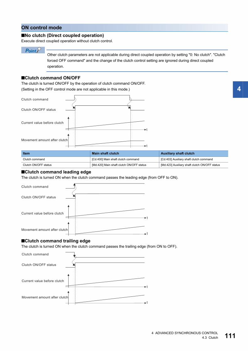
4
ON control mode
■No clutch (Direct coupled operation)Execute direct coupled operation without clutch control.
Other clutch parameters are not applicable during direct coupled operation by setting "0: No clutch". "Clutch
forced OFF command" and the change of the clutch control setting are ignored during direct coupled
operation.
■Clutch command ON/OFFThe clutch is turned ON/OFF by the operation of clutch command ON/OFF.
(Setting in the OFF control mode are not applicable in this mode.)
■Clutch command leading edgeThe clutch is turned ON when the clutch command passes the leading edge (from OFF to ON).
■Clutch command trailing edgeThe clutch is turned ON when the clutch command passes the trailing edge (from ON to OFF).
Item Main shaft clutch Auxiliary shaft clutch
Clutch command [Cd.400] Main shaft clutch command [Cd.403] Auxiliary shaft clutch command
Clutch ON/OFF status [Md.420] Main shaft clutch ON/OFF status [Md.423] Auxiliary shaft clutch ON/OFF status
t
t
Movement amount after clutch
Clutch command
Clutch ON/OFF status
Current value before clutch
t
tMovement amount after clutch
Clutch command
Clutch ON/OFF status
Current value before clutch
t
tMovement amount after clutch
Clutch command
Clutch ON/OFF status
Current value before clutch
4 ADVANCED SYNCHRONOUS CONTROL4.3 Clutch 111

11
■Address modeThe clutch is turned ON when the reference address reaches "Clutch ON address".
The movement amount after passing through the ON address is calculated as the output movement amount of the clutch
based on the reference address passing through, thereby controlling the clutch with an accurate movement amount.
■High speed input request [RD77MS]The clutch is turned ON when the high speed input request [DI] turns ON.
The following actions are required when using the high speed input request.
• Set the signal No. for the "High speed input request signal" clutch control setting.
• Set the external command signal used in "[Pr.95] External command signal selection", "4: High speed input request" in
"[Pr.42] External command function selection" and "1: Validates an external command" in "[Cd.8] External command valid"
for the applicable axis.
Item Main shaft clutch Auxiliary shaft clutch
Reference address The current value specified in "[Pr.406] Main shaft
clutch reference address setting"
("[Md.400] Current value after composite main
shaft gear" or "[Md.401] Current value per cycle
after main shaft gear")
The current value specified in "[Pr.423] Auxiliary
shaft clutch reference address setting"
(Auxiliary shaft current value (servo input axis
current value/synchronous encoder axis current
value) or "[Md.402] Current value per cycle after
auxiliary shaft gear")
Clutch ON address [Pr.407] Main shaft clutch ON address [Pr.424] Auxiliary shaft clutch ON address
Clutch ON/OFF status [Md.420] Main shaft clutch ON/OFF status [Md.423] Auxiliary shaft clutch ON/OFF status
t
tMovement amount after clutch
Clutch ON address
Clutch ON/OFF status
Current value specified inclutch reference addresssetting
t
t
Movement amount after clutch
[Cd.8] External command valid
Current value before clutch
Clutch ON/OFF status
High speed input request [DI]
24 ADVANCED SYNCHRONOUS CONTROL4.3 Clutch

4
■Main shaft clutch control request ON/OFF [RD77GF]The clutch is turned ON/OFF by ON/OFF operation of the link device assigned to the "Main shaft clutch control request".
(Setting in the OFF control mode are not applicable in this mode.)
The clutch is turned OFF when a communication error occurs in the station of the assigned link device.
The following actions are required when using the main shaft clutch control request.
• Assign the link device to the main shaft clutch control request with the link device external signal assignment function.
• Set "1: Validates an external command" in "[Cd.8] External command valid".
■Main shaft clutch control request leading edge [RD77GF]The clutch is turned ON when the link device assigned to the "Main shaft clutch control request" passes the leading edge
(from OFF to ON).
The clutch is turned OFF when a communication error occurs in the station of the assigned link device.
The following actions are required when using the main shaft clutch control request.
• Assign the link device to the main shaft clutch control request with the link device external signal assignment function.
• Set "1: Validates an external command" in "[Cd.8] External command valid".
Item Main shaft clutch Auxiliary shaft clutch
Clutch command Link device assigned to the main shaft clutch
control request with the link device external signal
assignment function
Link device assigned to the auxiliary shaft clutch
control request with the link device external signal
assignment function
Clutch ON/OFF status [Md.420] Main shaft clutch ON/OFF status [Md.423] Auxiliary shaft clutch ON/OFF status
t
t
Clutch ON/OFF status
Current value before clutch
Movement amount after clutch
Main shaft clutch control request
t
t
Clutch ON/OFF status
Current value before clutch
Movement amount after clutch
Main shaft clutch control request
4 ADVANCED SYNCHRONOUS CONTROL4.3 Clutch 113

11
■Main shaft clutch control request trailing edge [RD77GF]The clutch is turned ON when the link device assigned to the "Main shaft clutch control request" passes the trailing edge (from
ON to OFF).
The clutch is turned OFF when a communication error occurs in the station of the assigned link device.
The following actions are required when using the main shaft clutch control request.
• Assign the link device to the main shaft clutch control request with the link device external signal assignment function.
• Set "1: Validates an external command" in "[Cd.8] External command valid".
OFF control mode
■OFF control invalidClutch OFF control is not used. This setting is applicable only for execution with clutch ON control.
■One-shot OFFThe clutch is turned OFF after moving the distance "Movement amount before clutch OFF" (One-shot operation) after the
clutch command turn ON.
If "Movement amount before clutch OFF" is 0, "Clutch ON/OFF status" does not turn ON in order to turn back OFF
immediately.
Item Main shaft clutch Auxiliary shaft clutch
Clutch command [Cd.400] Main shaft clutch command [Cd.403] Auxiliary shaft clutch command
Clutch ON/OFF status [Md.420] Main shaft clutch ON/OFF status [Md.423] Auxiliary shaft clutch ON/OFF status
Movement amount before clutch OFF [Pr.410] Movement amount before main shaft
clutch OFF
[Pr.427] Movement amount before auxiliary shaft
clutch OFF
t
t
Clutch ON/OFF status
Current value before clutch
Movement amount after clutch
Main shaft clutch control request
t
t
Movement amount after clutch
Clutch ON/OFF status
Clutch command
Current value before clutch
Movement amount before clutch OFF
44 ADVANCED SYNCHRONOUS CONTROL4.3 Clutch

4
■Clutch command leading edgeThe clutch is turned OFF when the clutch command passes the leading edge (from OFF to ON).
■Clutch command trailing edgeThe clutch is turned OFF when the clutch command passes the trailing edge (from ON to OFF).
■Address modeThe clutch is turned OFF when the reference address reaches "Clutch OFF address".
The movement amount before passing through the OFF address is calculated as the output movement amount of the clutch
based on the reference address passing through, thereby controlling the clutch with an accurate movement amount.
Item Main shaft clutch Auxiliary shaft clutch
Reference address The current value specified in "[Pr.406] Main shaft
clutch reference address setting"
("[Md.400] Current value after composite main
shaft gear" or "[Md.401] Current value per cycle
after main shaft gear")
The current value specified in "[Pr.423] Auxiliary
shaft clutch reference address setting"
(Auxiliary shaft current value (servo input axis
current value/synchronous encoder axis current
value) or "[Md.402] Current value per cycle after
auxiliary shaft gear")
Clutch OFF address [Pr.409] Main shaft clutch OFF address [Pr.426] Auxiliary shaft clutch OFF address
Clutch ON/OFF status [Md.420] Main shaft clutch ON/OFF status [Md.423] Auxiliary shaft clutch ON/OFF status
t
t
Movement amount after clutch
Clutch ON/OFF status
Current value before clutch
Clutch command
t
t
Movement amount after clutch
Clutch ON/OFF status
Current value before clutch
Clutch command
t
tMovement amount after clutch
Clutch OFF address
Clutch ON/OFF status
Current value specified inclutch reference addresssetting
4 ADVANCED SYNCHRONOUS CONTROL4.3 Clutch 115

11
■High speed input request [RD77MS]The clutch is turned OFF when the high speed input request [DI] turns ON.
The following actions are required when using the high speed input request.
• Set the signal No. for the "High speed input request signal" clutch control setting.
• Set the external command signal used in "[Pr.95] External command signal selection", "4: High speed input request" in
"[Pr.42] External command function selection" and "1: Validates an external command" in "[Cd.8] External command valid"
for the applicable axis.
■Auxiliary shaft clutch control request leading edge [RD77GF]The clutch is turned ON when the link device assigned to the "Auxiliary shaft clutch control request" passes the leading edge
(from OFF to ON).
The clutch is turned OFF when a communication error occurs in the station of the assigned link device.
The following actions are required when using the auxiliary shaft clutch control request.
• Assign the link device to the auxiliary shaft clutch control request with the link device external signal assignment function.
• Set "1: Validates an external command" in "[Cd.8] External command valid".
■Auxiliary shaft clutch control request trailing edge [RD77GF]The clutch is turned ON when the link device assigned to the "Auxiliary shaft clutch control request" passes the trailing edge
(from ON to OFF).
The clutch is turned OFF when a communication error occurs in the station of the assigned link device.
The following actions are required when using the auxiliary shaft clutch control request.
• Assign the link device to the auxiliary shaft clutch control request with the link device external signal assignment function.
• Set "1: Validates an external command" in "[Cd.8] External command valid".
t
t
Movement amount after clutch
[Cd.8] External command valid
Current value before clutch
Clutch ON/OFF status
High speed input request [DI]
t
t
Clutch ON/OFF status
Current value before clutch
Movement amount after clutch
Auxiliary shaft clutch control request
t
t
Clutch ON/OFF status
Current value before clutch
Movement amount after clutch
Auxiliary shaft clutch control request
64 ADVANCED SYNCHRONOUS CONTROL4.3 Clutch

4
Smoothing method for clutchSet the clutch smoothing method in "[Pr.411] Main shaft clutch smoothing method" and "[Pr.428] Auxiliary shaft clutch
smoothing method".
The 2 types of clutch smoothing include the following.
• Time constant method smoothing
• Slippage method smoothing
When not using clutch smoothing, set "0: Direct" in the clutch smoothing method.
The operation of each smoothing method is shown below.
Time constant method smoothingSmoothing is processed with the time constant setting value in the smoothing time constant at clutch ON/OFF. After clutch ON
smoothing is complete, smoothing is processed with the time constant setting value when the speed of the input values
changes.
The movement amount between the clutch turning ON and OFF is not changed with smoothing.
Movement amount after clutch smoothing = Movement amount before clutch smoothing
■Time constant method exponential curve smoothingSet "1: Time constant method (Exponential)" in the clutch smoothing method.
Item Setting item Setting details/Setting value
Main shaft clutch Auxiliary shaft clutch
Clutch smoothing
method
[Pr.411]
Main shaft clutch smoothing
method
[Pr.428]
Auxiliary shaft clutch
smoothing method
• Set the clutch smoothing method.
■Set in decimal.
0: Direct
1: Time constant method (Exponent)
2: Time constant method (Linear)
3: Slippage method (Exponent)
4: Slippage method (Linear)
5: Slippage method (Linear: Input value follow up)
Item Setting item Setting details Setting value
Main shaft clutch Auxiliary shaft clutch
Clutch smoothing
time constant
[Pr.412]
Main shaft clutch smoothing
time constant
[Pr.429]
Auxiliary shaft clutch
smoothing time constant
• For smoothing with a time
constant method, set the
smoothing time constant.
■Set in decimal.
0 to 5000 [ms]
Item Main shaft clutch Auxiliary shaft clutch
Clutch ON/OFF status [Md.420] Main shaft clutch ON/OFF status [Md.423] Auxiliary shaft clutch ON/OFF status
Clutch smoothing status [Md.421] Main shaft clutch smoothing status [Md.424] Auxiliary shaft clutch smoothing status
t
t
63%
63%Speed after clutchsmoothing
Clutch smoothing time constant
Clutch ON/OFF status
Clutch smoothing status
Speed before clutchprocessing
4 ADVANCED SYNCHRONOUS CONTROL4.3 Clutch 117
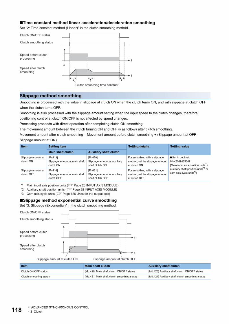
11
■Time constant method linear acceleration/deceleration smoothingSet "2: Time constant method (Linear)" in the clutch smoothing method.
Slippage method smoothingSmoothing is processed with the value in slippage at clutch ON when the clutch turns ON, and with slippage at clutch OFF
when the clutch turns OFF.
Smoothing is also processed with the slippage amount setting when the input speed to the clutch changes, therefore,
positioning control at clutch ON/OFF is not affected by speed changes.
Processing proceeds with direct operation after completing clutch ON smoothing.
The movement amount between the clutch turning ON and OFF is as follows after clutch smoothing.
Movement amount after clutch smoothing = Movement amount before clutch smoothing + (Slippage amount at OFF -
Slippage amount at ON)
*1 Main input axis position units (Page 28 INPUT AXIS MODULE)*2 Auxiliary shaft position units (Page 28 INPUT AXIS MODULE)*3 Cam axis cycle units (Page 126 Units for the output axis)
■Slippage method exponential curve smoothingSet "3: Slippage (Exponential)" in the clutch smoothing method.
Item Setting item Setting details Setting value
Main shaft clutch Auxiliary shaft clutch
Slippage amount at
clutch ON
[Pr.413]
Slippage amount at main shaft
clutch ON
[Pr.430]
Slippage amount at auxiliary
shaft clutch ON
For smoothing with a slippage
method, set the slippage amount
at clutch ON.
■Set in decimal.
0 to 2147483647
[Main input axis position units*1/
auxiliary shaft position units*2 or
cam axis cycle units*3]Slippage amount at
clutch OFF
[Pr.414]
Slippage amount at main shaft
clutch OFF
[Pr.431]
Slippage amount at auxiliary
shaft clutch OFF
For smoothing with a slippage
method, set the slippage amount
at clutch OFF.
Item Main shaft clutch Auxiliary shaft clutch
Clutch ON/OFF status [Md.420] Main shaft clutch ON/OFF status [Md.423] Auxiliary shaft clutch ON/OFF status
Clutch smoothing status [Md.421] Main shaft clutch smoothing status [Md.424] Auxiliary shaft clutch smoothing status
t
t
Speed after clutchsmoothing
Clutch smoothing time constant
Clutch ON/OFF status
Clutch smoothing status
Speed before clutchprocessing
t
t
Speed after clutchsmoothing
Clutch ON/OFF status
Clutch smoothing status
Speed before clutchprocessing
Slippage amount at clutch ON Slippage amount at clutch OFF
84 ADVANCED SYNCHRONOUS CONTROL4.3 Clutch

4
■Slippage method linear acceleration/deceleration smoothingSet "4: Slippage method (Linear)" or "5: Slippage method (Linear: Input value follow up)" in the clutch smoothing method.
The differences between "4: Slippage method (Linear)" and "5: Slippage method (Linear: Input value follow up)" are shown
below.
• When the input speed to the clutch is fixed
The operations of "4: Slippage method (Linear)" and "5: Slippage method (Linear: Input value follow up)" are same.
• When the input speed to the clutch is changed continuously and slightly
["4: Slippage method (Linear)" is set.]
The clutch smoothing status ON section is changed.
When the clutch smoothing status ON section is extended
When the clutch smoothing status ON section is shortened
Input speed during smoothing Smoothing method
4: Slippage method (Linear) 5: Slippage method (Linear: Input value follow up)
When the speed is fixed No differences
When the speed is changed
continuously and slightly
Smoothing section is changed. Smoothing section is fixed.
When the speed is changed largely The output speed is changed slightly. (The
average speed might be faster than the speed
before starting smoothing.)
The output speed is changed depending on the input speed. (When
the input speed is decelerated and accelerated again, the speed
might be accelerated rapidly.)
t
t
ON
ONOFF
OFF
Speed after clutchsmoothing
Clutch ON/OFF status
Clutch smoothing status
Speed before clutchprocessing
Slippage amount at clutch ON Slippage amount at clutch OFF
OFF
t
t
ON
ONOFF
Clamped at low speed
Output speed(Speed after clutchprocessing)
Clutch ON/OFF status
Clutch smoothing status
Input speed(Speed before clutchprocessing)
Slippage amount at clutch ON Slippage amount at clutch OFF
ON section is extended.
OFF
t
t
ON
ONOFF
Clamped at high speed
Output speed(Speed after clutchprocessing)
Clutch ON/OFF status
Clutch smoothing status
Input speed(Speed before clutchprocessing)
Slippage amount at clutch ON Slippage amount at clutch OFF
ON section is shortened.
4 ADVANCED SYNCHRONOUS CONTROL4.3 Clutch 119

12
["5: Slippage method (Linear: Input value follow up)" is set.]
The clutch smoothing status ON section is fixed.
• When the input speed is changed largely during smoothing
["4: Slippage method (Linear)" is set.]
The output speed is changed slightly compared to the change of the input speed.
(The average speed might be faster than the speed before starting smoothing.)
["5: Slippage method (Linear: Input value follow up)" is set.]
The output speed is changed depending on the input speed.
(When the input speed is decelerated and accelerated again, the speed might be accelerated rapidly.)
t
t
ON
ONOFF
OFF
Output speed(Speed after clutchprocessing)
Clutch ON/OFF status
Clutch smoothing status
Input speed(Speed before clutchprocessing)
Slippage amount at clutch ON Slippage amount at clutch OFF
ON section is fixed.
t
t
ON
ONOFF
OFF
Output speed(Speed after clutchprocessing)
Clutch ON/OFF status
Clutch smoothing status
Input speed(Speed before clutchprocessing)
Slippage amount at clutch ON Slippage amount at clutch OFF
The speed changes slightly.
t
t
ON
ONOFF
OFF
Output speed(Speed after clutchprocessing)
Clutch ON/OFF status
Clutch smoothing status
Input speed(Speed before clutchprocessing)
Slippage amount at clutch ON Slippage amount at clutch OFF
The speed changes depending on the input speed.
04 ADVANCED SYNCHRONOUS CONTROL4.3 Clutch
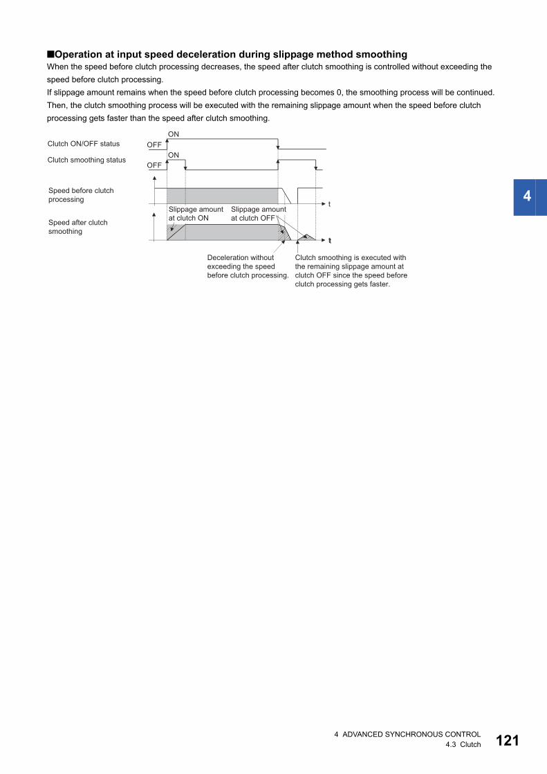
4
■Operation at input speed deceleration during slippage method smoothingWhen the speed before clutch processing decreases, the speed after clutch smoothing is controlled without exceeding the
speed before clutch processing.
If slippage amount remains when the speed before clutch processing becomes 0, the smoothing process will be continued.
Then, the clutch smoothing process will be executed with the remaining slippage amount when the speed before clutch
processing gets faster than the speed after clutch smoothing.
t
t
ON
ONOFF
OFF
Speed after clutchsmoothing
Clutch ON/OFF status
Clutch smoothing status
Speed before clutchprocessing
t
Clutch smoothing is executed withthe remaining slippage amount atclutch OFF since the speed beforeclutch processing gets faster.
Deceleration withoutexceeding the speedbefore clutch processing.
Slippage amountat clutch ON
Slippage amount at clutch OFF
4 ADVANCED SYNCHRONOUS CONTROL4.3 Clutch 121
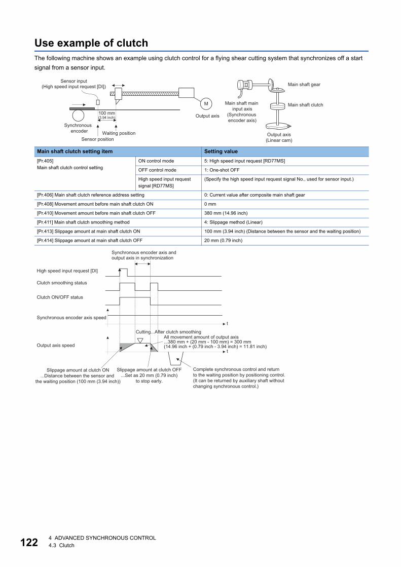
12
Use example of clutchThe following machine shows an example using clutch control for a flying shear cutting system that synchronizes off a start
signal from a sensor input.
Main shaft clutch setting item Setting value
[Pr.405]
Main shaft clutch control setting
ON control mode 5: High speed input request [RD77MS]
OFF control mode 1: One-shot OFF
High speed input request
signal [RD77MS]
(Specify the high speed input request signal No., used for sensor input.)
[Pr.406] Main shaft clutch reference address setting 0: Current value after composite main shaft gear
[Pr.408] Movement amount before main shaft clutch ON 0 mm
[Pr.410] Movement amount before main shaft clutch OFF 380 mm (14.96 inch)
[Pr.411] Main shaft clutch smoothing method 4: Slippage method (Linear)
[Pr.413] Slippage amount at main shaft clutch ON 100 mm (3.94 inch) (Distance between the sensor and the waiting position)
[Pr.414] Slippage amount at main shaft clutch OFF 20 mm (0.79 inch)
Main shaft gear
Main shaft clutch
Output axis(Linear cam)
Main shaft main input axis
(Synchronous encoder axis)
Sensor input(High speed input request [DI])
Synchronous encoder
M
Output axis
Waiting positionSensor position
100 mm(3.94 inch)
High speed input request [DI]
Clutch smoothing status
Clutch ON/OFF status
Synchronous encoder axis speed
Output axis speed
Slippage amount at clutch ON...Distance between the sensor and
the waiting position (100 mm (3.94 inch))
Slippage amount at clutch OFF...Set as 20 mm (0.79 inch)
to stop early.
Complete synchronous control and return to the waiting position by positioning control. (It can be returned by auxiliary shaft without changing synchronous control.)
All movement amount of output axis...380 mm + (20 mm - 100 mm) = 300 mm(14.96 inch + (0.79 inch - 3.94 inch) = 11.81 inch)
Cutting...After clutch smoothing
Synchronous encoder axis and output axis in synchronization
t
t
24 ADVANCED SYNCHRONOUS CONTROL4.3 Clutch

4
4.4 Speed Change Gear Module
Overview of speed change gear moduleA speed change gear module is used to change the input speed from the main shaft/auxiliary shaft/composite auxiliary shaft
gear during operation. When not using a speed change gear module, set "0: No speed change gear" in "[Pr.434] Speed
change gear".
With speed change from a speed change gear module, operation is executed with linear acceleration/deceleration based on
the setting for the speed change gear smoothing time constant.
t
100000 50000 -50000
100000 100000 100000
t
Output value
Input value
Speed change gear
[Pr.434] Speed change gear[Pr.435] Speed change gear
smoothing time constant[Pr.436] Speed change ratio:
Numerator[Pr.437] Speed change ratio:
Denominator
Output axis
Speed change gear
Speed change gear
Speed change gear
Main shaft clutch
Compositeauxiliary shaftgear
Cam
Auxiliary shaftclutch
[Arrangement the speed change gear]Arranged on one of "Main shaft side","Auxiliary shaft side" or "After composite auxiliary shaft gear".
[Pr.436] Speed change ratio:Numerator
[Pr.437] Speed change ratio:Denominator
Input value speed before speed change
Input value speed before speed change
[Pr.435] Speed change gear smoothing time constant
[Pr.435] Speed change gear smoothing time constant
4 ADVANCED SYNCHRONOUS CONTROL4.4 Speed Change Gear Module 123
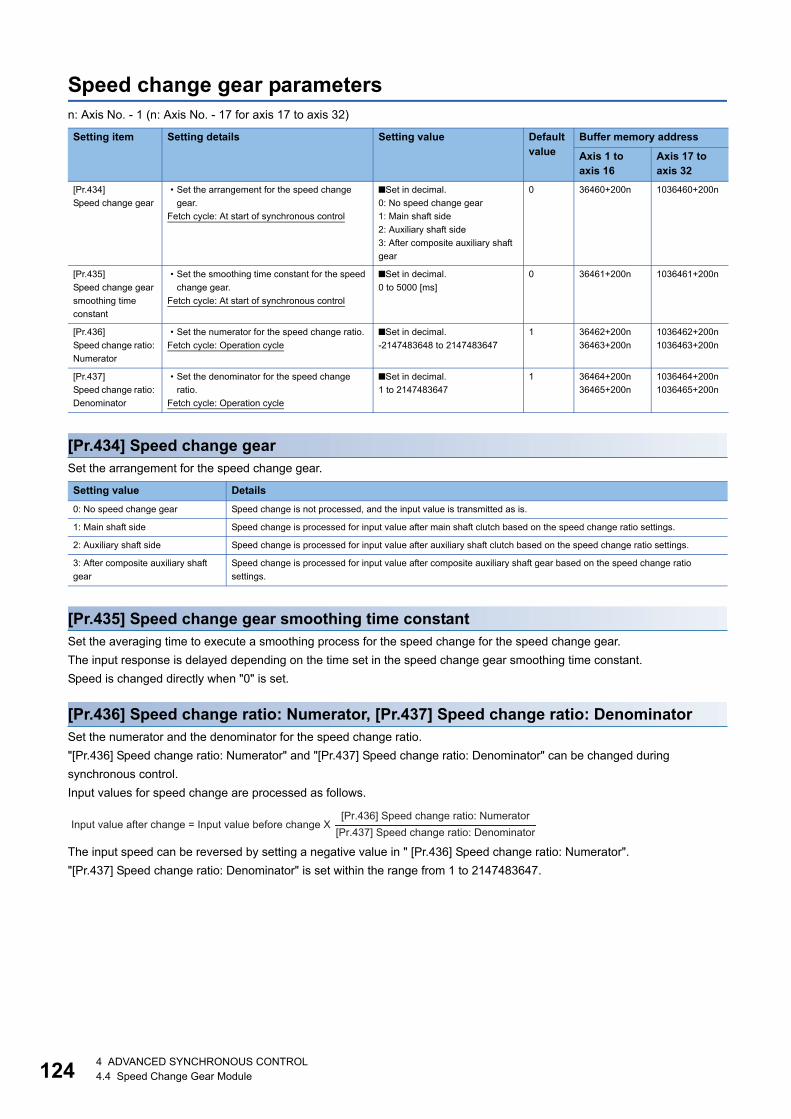
12
Speed change gear parametersn: Axis No. - 1 (n: Axis No. - 17 for axis 17 to axis 32)
[Pr.434] Speed change gearSet the arrangement for the speed change gear.
[Pr.435] Speed change gear smoothing time constantSet the averaging time to execute a smoothing process for the speed change for the speed change gear.
The input response is delayed depending on the time set in the speed change gear smoothing time constant.
Speed is changed directly when "0" is set.
[Pr.436] Speed change ratio: Numerator, [Pr.437] Speed change ratio: DenominatorSet the numerator and the denominator for the speed change ratio.
"[Pr.436] Speed change ratio: Numerator" and "[Pr.437] Speed change ratio: Denominator" can be changed during
synchronous control.
Input values for speed change are processed as follows.
The input speed can be reversed by setting a negative value in " [Pr.436] Speed change ratio: Numerator".
"[Pr.437] Speed change ratio: Denominator" is set within the range from 1 to 2147483647.
Setting item Setting details Setting value Default value
Buffer memory address
Axis 1 to axis 16
Axis 17 to axis 32
[Pr.434]
Speed change gear
• Set the arrangement for the speed change
gear.
Fetch cycle: At start of synchronous control
■Set in decimal.
0: No speed change gear
1: Main shaft side
2: Auxiliary shaft side
3: After composite auxiliary shaft
gear
0 36460+200n 1036460+200n
[Pr.435]
Speed change gear
smoothing time
constant
• Set the smoothing time constant for the speed
change gear.
Fetch cycle: At start of synchronous control
■Set in decimal.
0 to 5000 [ms]
0 36461+200n 1036461+200n
[Pr.436]
Speed change ratio:
Numerator
• Set the numerator for the speed change ratio.
Fetch cycle: Operation cycle
■Set in decimal.
-2147483648 to 2147483647
1 36462+200n
36463+200n
1036462+200n
1036463+200n
[Pr.437]
Speed change ratio:
Denominator
• Set the denominator for the speed change
ratio.
Fetch cycle: Operation cycle
■Set in decimal.
1 to 2147483647
1 36464+200n
36465+200n
1036464+200n
1036465+200n
Setting value Details
0: No speed change gear Speed change is not processed, and the input value is transmitted as is.
1: Main shaft side Speed change is processed for input value after main shaft clutch based on the speed change ratio settings.
2: Auxiliary shaft side Speed change is processed for input value after auxiliary shaft clutch based on the speed change ratio settings.
3: After composite auxiliary shaft
gear
Speed change is processed for input value after composite auxiliary shaft gear based on the speed change ratio
settings.
Input value after change = Input value before change X[Pr.436] Speed change ratio: Numerator
[Pr.437] Speed change ratio: Denominator
44 ADVANCED SYNCHRONOUS CONTROL4.4 Speed Change Gear Module

4
4.5 Output Axis Module
Overview of output axis moduleFor the output axis module, the cam axis current value per cycle is calculated based on the input value (the output value from
a speed change gear), and is converted based on the set cam data. The feed current value which is a command is output to
the servo amplifier.
[Md.20] Feed current value
Cam axis phase compensation
processing
Cam conversion processing
[Md.410] Execute cam No.[Md.411] Execute cam stroke amount
[Pr.439] Cam axis length per cycle[Pr.440] Cam No.[Pr.441] Cam stroke amount
[Pr.444] Cam axis phase compensation advance time
[Pr.445] Cam axis phase compensation time constant
[Pr.438] Cam axis cycle unit setting
[Pr.446] Synchronous control deceleration time(No influence on control)
(Use only at deceleration stop)
Input value
Cam data
Output axis smoothing processing
[Pr.447] Output axis smoothing time constant
[Md.407] Cam axis current value per cycle[Md.408] Cam reference position[Md.409] Cam axis feed current value
[Md.406] Cam axis phase compensation amount
4 ADVANCED SYNCHRONOUS CONTROL4.5 Output Axis Module 125

12
Units for the output axisThe position units for the output axis are shown below based on the setting "[Pr.1] Unit setting".
Cam axis cycle units are shown below based on the setting "[Pr.438] Cam axis cycle unit setting".
Setting value of "[Pr.1] Unit setting" Output axis position unit Range
0: mm 10-4 mm
( 10-1 m)
-214748.3648 to 214748.3647 [mm]
(-214748364.8 to 214748364.7 [m])
1: inch 10-5 inch -21474.83648 to 21474.83647 [inch]
2: degree 10-5 degree -21474.83648 to 21474.83647 [degree]
3: pulse pulse -2147483648 to 2147483647 [pulse]
Setting value of "[Pr.438] Cam axis cycle unit setting"
Cam axis cycle unit Range
Unit setting selection Control unit
Number of decimal places
0: Use units of main input
axis
Servo input axis position unit (Page 29 Servo input axis position units)
Synchronous encoder axis position unit (Page 36 Synchronous encoder axis position
units)
1: Use units of this setting 0: mm 0 mm -2147483648 to 2147483647 [mm]
9 10-9 mm -2.147483648 to 2.147483647 [mm]
1: inch 0 inch -2147483648 to 2147483647 [inch]
9 10-9 inch -2.147483648 to 2.147483647 [inch]
2: degree 0 degree -2147483648 to 2147483647 [degree]
9 10-9 degree -2.147483648 to 2.147483647 [degree]
3: pulse 0 pulse -2147483648 to 2147483647 [pulse]
9 10-9 pulse -2.147483648 to 2.147483647 [pulse]
64 ADVANCED SYNCHRONOUS CONTROL4.5 Output Axis Module
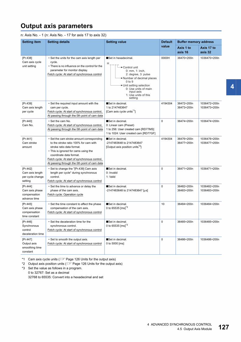
4
Output axis parametersn: Axis No. - 1 (n: Axis No. - 17 for axis 17 to axis 32)
*1 Cam axis cycle units (Page 126 Units for the output axis)*2 Output axis position units (Page 126 Units for the output axis)*3 Set the value as follows in a program.
0 to 32767: Set as a decimal32768 to 65535: Convert into a hexadecimal and set
Setting item Setting details Setting value Default value
Buffer memory address
Axis 1 to axis 16
Axis 17 to axis 32
[Pr.438]
Cam axis cycle
unit setting
• Set the units for the cam axis length per
cycle.
• There is no influence on the control for the
parameter for monitor display.
Fetch cycle: At start of synchronous control
■Set in hexadecimal. 0000H 36470+200n 1036470+200n
[Pr.439]
Cam axis length
per cycle
• Set the required input amount with the
cam per cycle.
Fetch cycle: At start of synchronous control,
At passing through the 0th point of cam data
■Set in decimal.
1 to 2147483647
[Cam axis cycle units*1]
4194304 36472+200n
36473+200n
1036472+200n
1036473+200n
[Pr.440]
Cam No.
• Set the cam No.
Fetch cycle: At start of synchronous control,
At passing through the 0th point of cam data
■Set in decimal.
0: Linear cam (Preset)
1 to 256: User created cam [RD77MS]
1 to 1024: User created cam [RD77GF]
0 36474+200n 1036474+200n
[Pr.441]
Cam stroke
amount
• Set the cam stroke amount corresponding
to the stroke ratio 100% for cam with
stroke ratio data format.
• This is ignored for cams using the
coordinate data format.
Fetch cycle: At start of synchronous control,
At passing through the 0th point of cam data
■Set in decimal.
-2147483648 to 2147483647
[Output axis position units*2]
4194304 36476+200n
36477+200n
1036476+200n
1036477+200n
[Pr.442]
Cam axis length
per cycle change
setting
• Set to change the "[Pr.439] Cam axis
length per cycle" during synchronous
control.
Fetch cycle: At start of synchronous control
■Set in decimal.
0: Invalid
1: Valid
0 36471+200n 1036471+200n
[Pr.444]
Cam axis phase
compensation
advance time
• Set the time to advance or delay the
phase of the cam axis.
Fetch cycle: Operation cycle
■Set in decimal.
-2147483648 to 2147483647 [s]
0 36482+200n
36483+200n
1036482+200n
1036483+200n
[Pr.445]
Cam axis phase
compensation
time constant
• Set the time constant to affect the phase
compensation of the cam axis.
Fetch cycle: At start of synchronous control
■Set in decimal.
0 to 65535 [ms]*310 36484+200n 1036484+200n
[Pr.446]
Synchronous
control
deceleration time
• Set the deceleration time for the
synchronous control.
Fetch cycle: At start of synchronous control
■Set in decimal.
0 to 65535 [ms]*30 36485+200n 1036485+200n
[Pr.447]
Output axis
smoothing time
constant
• Set to smooth the output axis.
Fetch cycle: At start of synchronous control
■Set in decimal.
0 to 5000 [ms]
0 36486+200n 1036486+200n
H _ _ _ _Control unit
0: mm, 1: inch,2: degree, 3: pulse
Number of decimal places0 to 9
Unit setting selection0: Use units of main
input axis1: Use units of this
setting
4 ADVANCED SYNCHRONOUS CONTROL4.5 Output Axis Module 127
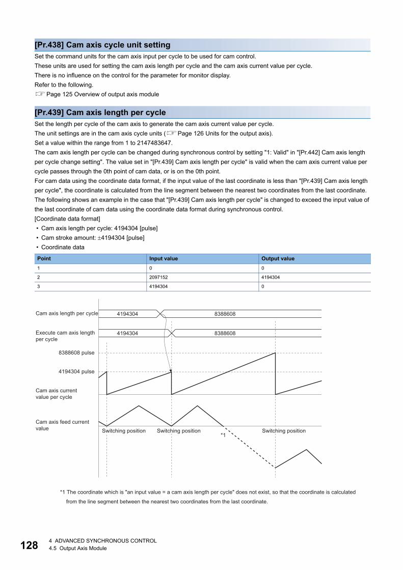
12
[Pr.438] Cam axis cycle unit settingSet the command units for the cam axis input per cycle to be used for cam control.
These units are used for setting the cam axis length per cycle and the cam axis current value per cycle.
There is no influence on the control for the parameter for monitor display.
Refer to the following.
Page 125 Overview of output axis module
[Pr.439] Cam axis length per cycleSet the length per cycle of the cam axis to generate the cam axis current value per cycle.
The unit settings are in the cam axis cycle units (Page 126 Units for the output axis).
Set a value within the range from 1 to 2147483647.
The cam axis length per cycle can be changed during synchronous control by setting "1: Valid" in "[Pr.442] Cam axis length
per cycle change setting". The value set in "[Pr.439] Cam axis length per cycle" is valid when the cam axis current value per
cycle passes through the 0th point of cam data, or is on the 0th point.
For cam data using the coordinate data format, if the input value of the last coordinate is less than "[Pr.439] Cam axis length
per cycle", the coordinate is calculated from the line segment between the nearest two coordinates from the last coordinate.
The following shows an example in the case that "[Pr.439] Cam axis length per cycle" is changed to exceed the input value of
the last coordinate of cam data using the coordinate data format during synchronous control.
[Coordinate data format]
• Cam axis length per cycle: 4194304 [pulse]
• Cam stroke amount: 4194304 [pulse]
• Coordinate data
Point Input value Output value
1 0 0
2 2097152 4194304
3 4194304 0
4194304 8388608
8388608 pulse
4194304 pulse
4194304 8388608
*1
Cam axis feed current value
Cam axis currentvalue per cycle
Execute cam axis lengthper cycle
Cam axis length per cycle
*1 The coordinate which is "an input value = a cam axis length per cycle" does not exist, so that the coordinate is calculated
from the line segment between the nearest two coordinates from the last coordinate.
Switching position Switching position Switching position
84 ADVANCED SYNCHRONOUS CONTROL4.5 Output Axis Module

4
[Pr.440] Cam No.Set the cam No. for cam control.
Cam No.0 operates as a linear cam for 100% of its stroke ratio along the cam axis length per cycle.
The cam No. can be changed during synchronous control.
The value set in "[Pr.440] Cam No." is valid when the cam axis current value per cycle passes through the 0th point of cam
data, or is on the 0th point.
[Pr.441] Cam stroke amountSet the cam stroke amount corresponding to a 100% stroke ratio in output axis position units (Page 126 Units for the
output axis) for cam control using the stroke ratio data format.
The cam stroke amount can be changed during synchronous control.
The value set in "[Pr.441] Cam stroke amount" is valid when the cam axis current value per cycle passes through the 0th point
of cam data, or is on the 0th point.
The setting value is ignored for a cam using the coordinate data format.
[Pr.442] Cam axis length per cycle change settingSet to change the cam axis length per cycle during synchronous control.
It can be changed for cam control using the cam No.0 (linear cam), the stroke ratio data format, and the coordinate data
format. However, it cannot be changed when the cam data whose starting point is other than 0 is used for the stroke ratio data
format.
[Pr.444] Cam axis phase compensation advance timeSet the time to advance or delay the phase of the cam axis current value per cycle in the cam control.
If the setting time is too long, the system experiences overshoot or undershoot at acceleration/deceleration of the input speed.
In this case, set a longer time to affect the phase compensation amount in "[Pr.445] Cam axis phase compensation time
constant".
Setting value Details
0: Invalid The cam axis length per cycle cannot be changed during synchronous control.
1: Valid The value set in "[Pr.439] Cam axis length per cycle" is valid when the cam axis current value per cycle passes through
the 0th point of cam data, or is on the 0th point.
Setting value Details
1 to 2147483647 [s] Advance the phase according to the setting time.
0 [s] Do not execute phase compensation.
-2147483648 to -1 [s] Delay the phase according to the setting time.
4 ADVANCED SYNCHRONOUS CONTROL4.5 Output Axis Module 129
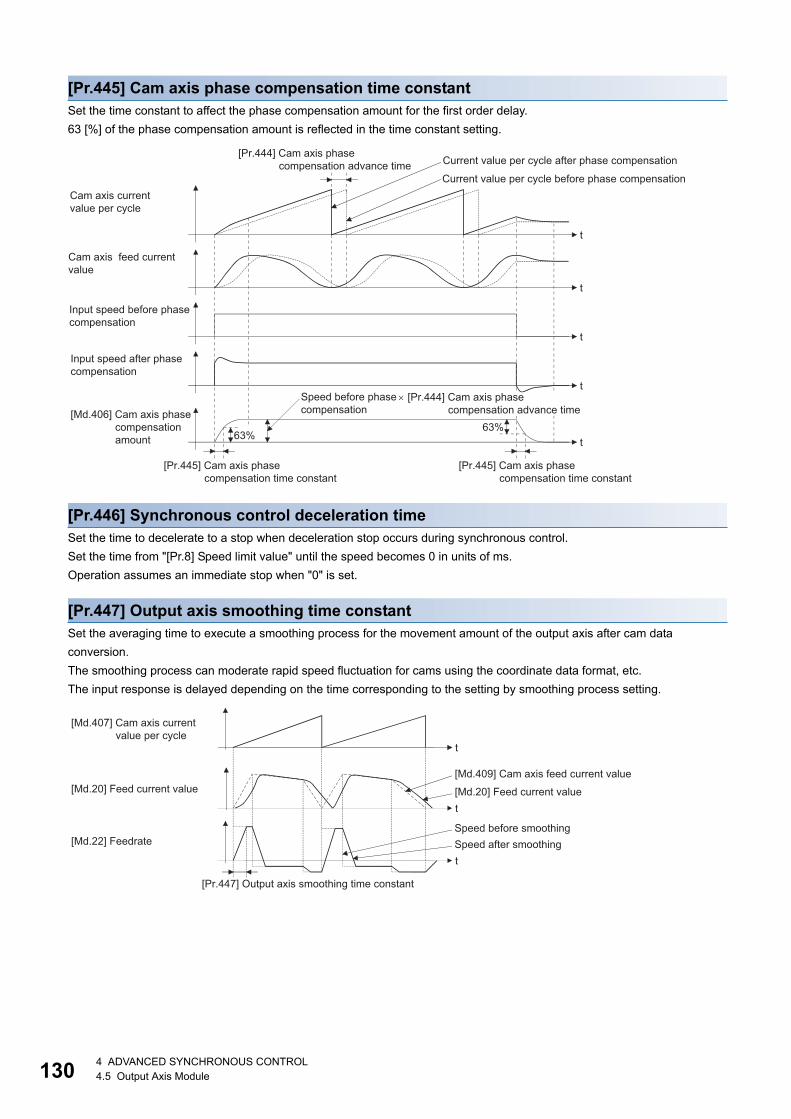
13
[Pr.445] Cam axis phase compensation time constantSet the time constant to affect the phase compensation amount for the first order delay.
63 [%] of the phase compensation amount is reflected in the time constant setting.
[Pr.446] Synchronous control deceleration timeSet the time to decelerate to a stop when deceleration stop occurs during synchronous control.
Set the time from "[Pr.8] Speed limit value" until the speed becomes 0 in units of ms.
Operation assumes an immediate stop when "0" is set.
[Pr.447] Output axis smoothing time constantSet the averaging time to execute a smoothing process for the movement amount of the output axis after cam data
conversion.
The smoothing process can moderate rapid speed fluctuation for cams using the coordinate data format, etc.
The input response is delayed depending on the time corresponding to the setting by smoothing process setting.
t
t
t
t63%63%
t
Speed before phase compensation [Md.406] Cam axis phase
compensation amount
Input speed before phase compensation
Input speed after phase compensation
Cam axis feed current value
Current value per cycle before phase compensation
Current value per cycle after phase compensation
Cam axis currentvalue per cycle
[Pr.445] Cam axis phasecompensation time constant
[Pr.445] Cam axis phasecompensation time constant
[Pr.444] Cam axis phase compensation advance time
× [Pr.444] Cam axis phase compensation advance time
t
t
t
[Md.407] Cam axis currentvalue per cycle
Speed before smoothingSpeed after smoothing
[Md.20] Feed current value
[Md.22] Feedrate
[Md.409] Cam axis feed current value
[Md.20] Feed current value
[Pr.447] Output axis smoothing time constant
04 ADVANCED SYNCHRONOUS CONTROL4.5 Output Axis Module

4
4.6 Synchronous Control Change Function
Overview of synchronous control change functionThis function can change the cam reference position, the cam axis current value per cycle and the current value per cycle
after the main/auxiliary shaft gear during the synchronous control.
The following 5 methods exist for the synchronous control change function. Refer to the following on each change command.
Page 131 Synchronous control change control data
Synchronous control change control datan: Axis No. - 1 (n: Axis No. - 17 for axis 17 to axis 32)
*1 Set the value as follows in a program.0 to 32767: Set as a decimal.32768 to 65535: Convert into a hexadecimal and set.
[Cd.406] Synchronous control change requestSet "1" to initiate "[Cd.407] Synchronous control change command". The Simple Motion module resets the value to "0"
automatically after completion of the synchronous control change.
The setting is initialized to "0" when starting synchronous control.
Synchronous control change command Application Output axis operation
Cam reference position movement Adjust the cam reference position by the
movement amount.
Operated
Change cam axis current value per cycle Change the cam axis current value per cycle. None
Change current value per cycle after main shaft
gear
Change the current value per cycle after main shaft
gear.
None
Change current value per cycle after auxiliary shaft
gear
Change the current value per cycle after auxiliary
shaft gear.
None
Cam axis current value per cycle movement Adjust the phase of the cam axis by the movement
amount.
Operated
Setting item Setting details Setting value Default value
Buffer memory address
Axis 1 to axis 16
Axis 17 to axis 32
[Cd.406]
Synchronous
control change
request
• Set "1" to initiate a synchronous control
change command request. The value is reset
to "0" automatically after completion of the
synchronous control change.
Fetch cycle: Operation cycle
■Set in decimal.
1: Synchronous control change
request
0 44086+20n 1044086+20n
[Cd.407]
Synchronous
control change
command
• Set the synchronous control change
command.
Fetch cycle: At requesting synchronous control
change
■Set in decimal.
0: Cam reference position movement
1: Change cam axis current value per
cycle
2: Change current value per cycle after
main shaft gear
3: Change current value per cycle after
auxiliary shaft gear
4: Cam axis current value per cycle
movement
0 44087+20n 1044087+20n
[Cd.408]
Synchronous
control change
value
• Set the change value for synchronous control
change processing.
Fetch cycle: At requesting synchronous control
change
■Set in decimal.
-2147483648 to 2147483647
(Refer to the detailed explanation for
units.)
0 44088+20n
44089+20n
1044088+20n
1044089+20n
[Cd.409]
Synchronous
control reflection
time
• Set the reflection time for synchronous
control change processing.
Fetch cycle: At requesting synchronous control
change
■Set in decimal.
0 to 65535 [ms]*10 44090+20n 1044090+20n
4 ADVANCED SYNCHRONOUS CONTROL4.6 Synchronous Control Change Function 131
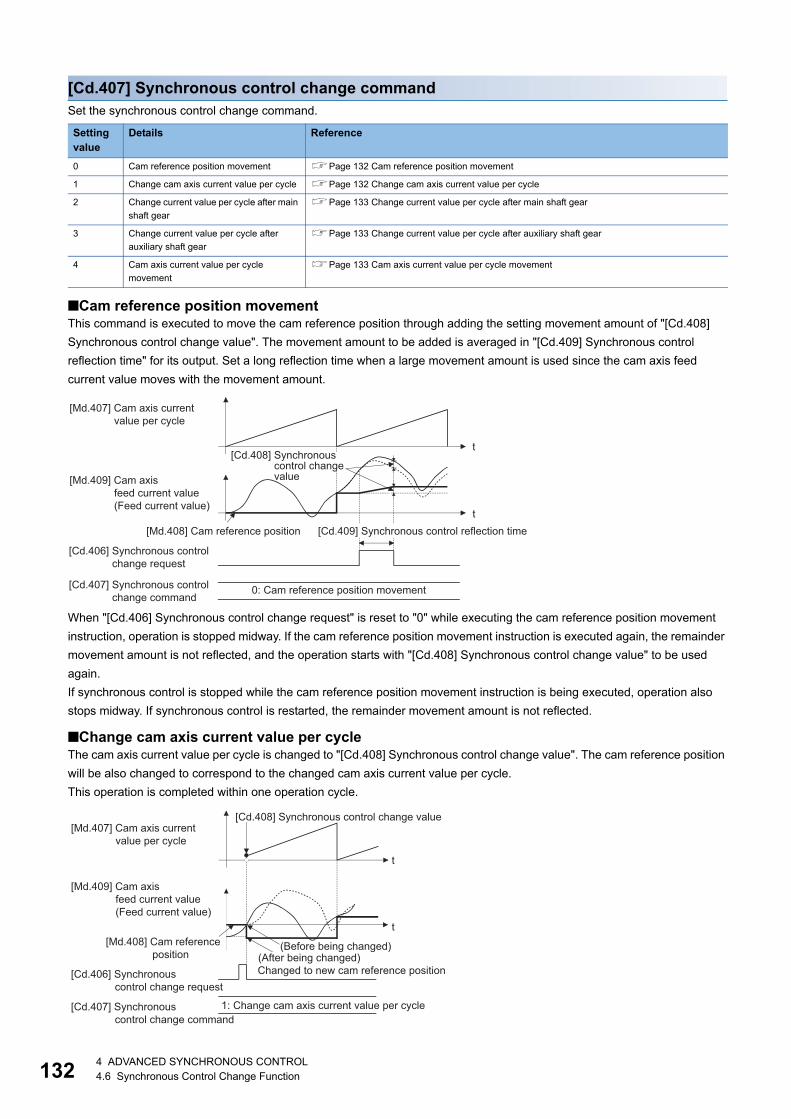
13
[Cd.407] Synchronous control change commandSet the synchronous control change command.
■Cam reference position movementThis command is executed to move the cam reference position through adding the setting movement amount of "[Cd.408]
Synchronous control change value". The movement amount to be added is averaged in "[Cd.409] Synchronous control
reflection time" for its output. Set a long reflection time when a large movement amount is used since the cam axis feed
current value moves with the movement amount.
When "[Cd.406] Synchronous control change request" is reset to "0" while executing the cam reference position movement
instruction, operation is stopped midway. If the cam reference position movement instruction is executed again, the remainder
movement amount is not reflected, and the operation starts with "[Cd.408] Synchronous control change value" to be used
again.
If synchronous control is stopped while the cam reference position movement instruction is being executed, operation also
stops midway. If synchronous control is restarted, the remainder movement amount is not reflected.
■Change cam axis current value per cycleThe cam axis current value per cycle is changed to "[Cd.408] Synchronous control change value". The cam reference position
will be also changed to correspond to the changed cam axis current value per cycle.
This operation is completed within one operation cycle.
Setting value
Details Reference
0 Cam reference position movement Page 132 Cam reference position movement
1 Change cam axis current value per cycle Page 132 Change cam axis current value per cycle
2 Change current value per cycle after main
shaft gear
Page 133 Change current value per cycle after main shaft gear
3 Change current value per cycle after
auxiliary shaft gear
Page 133 Change current value per cycle after auxiliary shaft gear
4 Cam axis current value per cycle
movement
Page 133 Cam axis current value per cycle movement
t
t[Md.408] Cam reference position
[Cd.408] Synchronous control changevalue
[Md.407] Cam axis currentvalue per cycle
[Md.409] Cam axis feed current value(Feed current value)
[Cd.409] Synchronous control reflection time
[Cd.406] Synchronous control change request
[Cd.407] Synchronous control change command
0: Cam reference position movement
t
t
[Cd.408] Synchronous control change value[Md.407] Cam axis current
value per cycle
[Md.409] Cam axis feed current value(Feed current value)
[Cd.406] Synchronous control change request
[Cd.407] Synchronous control change command
1: Change cam axis current value per cycle
[Md.408] Cam reference position (After being changed)
Changed to new cam reference position
(Before being changed)
24 ADVANCED SYNCHRONOUS CONTROL4.6 Synchronous Control Change Function

4
■Change current value per cycle after main shaft gearThe current value per cycle after main shaft gear is changed to the value set in "[Cd.408] Synchronous control change value".
This operation is completed within one operation cycle.
Clutch control is not executed if the current value per cycle after main shaft gear (the value before being changed and after
being changed) has already passed through the ON/OFF address in address mode.
■Change current value per cycle after auxiliary shaft gearThe current value per cycle after auxiliary shaft gear is changed to the value set in "[Cd.408] Synchronous control change
value".
This operation is completed within one operation cycle.
Clutch control is not executed if the current value per cycle after the auxiliary shaft gear (the value before being changed and
after being changed) has already passed through the ON/OFF address in address mode.
■Cam axis current value per cycle movementThis command is executed to move the cam axis current value per cycle through adding the setting movement amount of
"[Cd.408] Synchronous control change value". The movement amount to be added is averaged in "[Cd.409] Synchronous
control reflection time" for its output.
Set a long reflection time when a large movement amount is used since the cam axis feed current value moves with the
movement amount.
[Cd.408] Synchronous control change valueSet the change value for synchronous control change processing as follows.
[Cd.407] Synchronous control change command
[Cd.408] Synchronous control change value
Setting range Unit Setting details
0: Cam reference position movement -2147483648 to
2147483647
Output axis position
unit
• Set the movement amount of the cam reference position.
• It moves within the range from -2147483648 to 2147483647.
1: Change cam axis current value per
cycle
Cam axis cycle unit • Set the change current value per cycle.
• The setting value is converted within the range from 0 to (Cam axis
length per cycle - 1).2: Change current value per cycle after
main shaft gear
3: Change current value per cycle after
auxiliary shaft gear
4: Cam axis current value per cycle
movement
• Set the movement amount of the cam axis current value per cycle.
• It moves within the range from -2147483648 to 2147483647.
t
[Md.407] Cam axis currentvalue per cycle
[Md.409] Cam axis feed current value(Feed current value)
[Cd.406] Synchronous control change request
[Cd.407] Synchronous control change command
4: Cam axis current value per cycle movement
[Cd.409] Synchronous control reflection time[Md.408] Cam reference position
[Cd.408] Synchronous control change value
4 ADVANCED SYNCHRONOUS CONTROL4.6 Synchronous Control Change Function 133

13
[Cd.409] Synchronous control reflection timeSet the reflection time for synchronous control change processing as follows.
[Cd.407] Synchronous control change command
Setting details for "[Cd.409] Synchronous control reflection time"
0: Cam reference position movement The time to reflect the movement amount to the cam reference position.
1: Change cam axis current value per
cycle
Setting not required.
2: Change current value per cycle after
main shaft gear
3: Change current value per cycle after
auxiliary shaft gear
4: Cam axis current value per cycle
movement
The time to reflect the movement amount to the cam axis current value per cycle.
44 ADVANCED SYNCHRONOUS CONTROL4.6 Synchronous Control Change Function
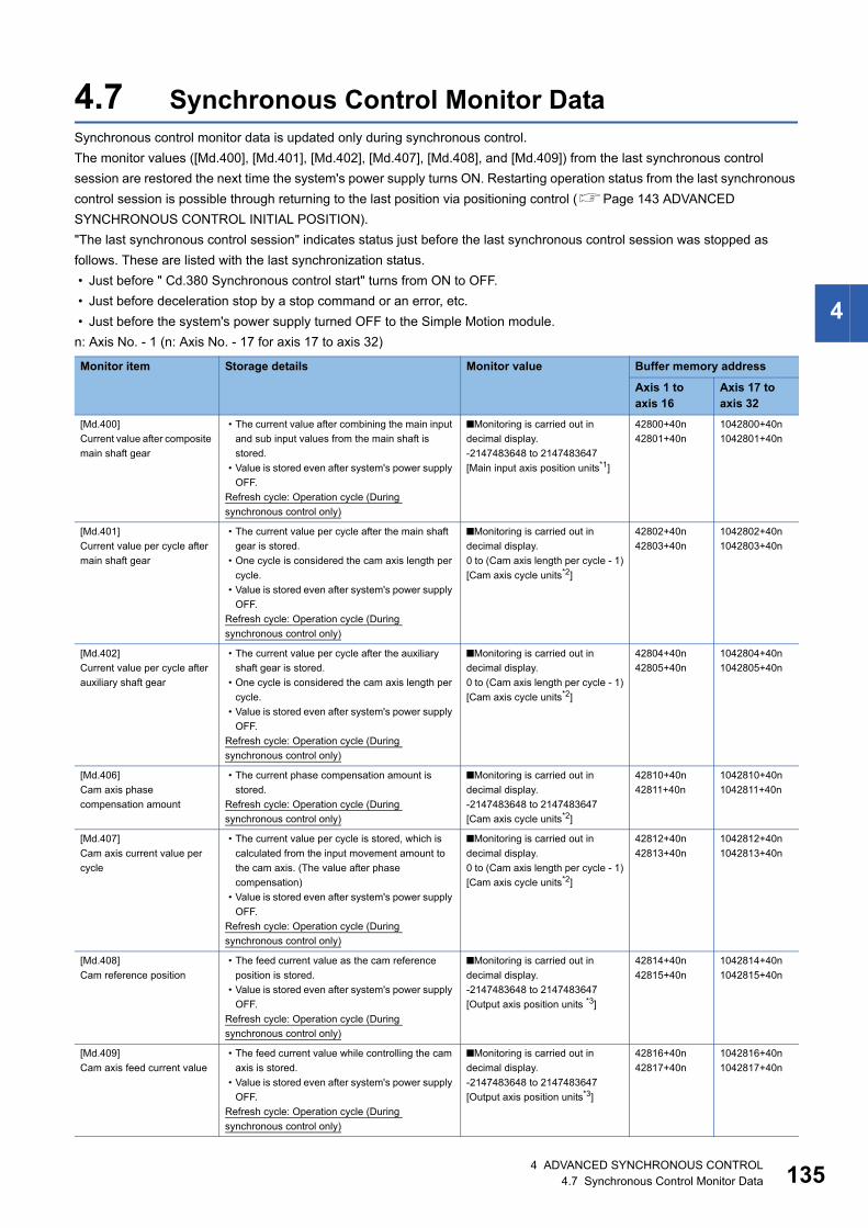
4
4.7 Synchronous Control Monitor DataSynchronous control monitor data is updated only during synchronous control.
The monitor values ([Md.400], [Md.401], [Md.402], [Md.407], [Md.408], and [Md.409]) from the last synchronous control
session are restored the next time the system's power supply turns ON. Restarting operation status from the last synchronous
control session is possible through returning to the last position via positioning control (Page 143 ADVANCED
SYNCHRONOUS CONTROL INITIAL POSITION).
"The last synchronous control session" indicates status just before the last synchronous control session was stopped as
follows. These are listed with the last synchronization status.
• Just before " Cd.380 Synchronous control start" turns from ON to OFF.
• Just before deceleration stop by a stop command or an error, etc.
• Just before the system's power supply turned OFF to the Simple Motion module.
n: Axis No. - 1 (n: Axis No. - 17 for axis 17 to axis 32)
Monitor item Storage details Monitor value Buffer memory address
Axis 1 to axis 16
Axis 17 to axis 32
[Md.400]
Current value after composite
main shaft gear
• The current value after combining the main input
and sub input values from the main shaft is
stored.
• Value is stored even after system's power supply
OFF.
Refresh cycle: Operation cycle (During
synchronous control only)
■Monitoring is carried out in
decimal display.
-2147483648 to 2147483647
[Main input axis position units*1]
42800+40n
42801+40n
1042800+40n
1042801+40n
[Md.401]
Current value per cycle after
main shaft gear
• The current value per cycle after the main shaft
gear is stored.
• One cycle is considered the cam axis length per
cycle.
• Value is stored even after system's power supply
OFF.
Refresh cycle: Operation cycle (During
synchronous control only)
■Monitoring is carried out in
decimal display.
0 to (Cam axis length per cycle - 1)
[Cam axis cycle units*2]
42802+40n
42803+40n
1042802+40n
1042803+40n
[Md.402]
Current value per cycle after
auxiliary shaft gear
• The current value per cycle after the auxiliary
shaft gear is stored.
• One cycle is considered the cam axis length per
cycle.
• Value is stored even after system's power supply
OFF.
Refresh cycle: Operation cycle (During
synchronous control only)
■Monitoring is carried out in
decimal display.
0 to (Cam axis length per cycle - 1)
[Cam axis cycle units*2]
42804+40n
42805+40n
1042804+40n
1042805+40n
[Md.406]
Cam axis phase
compensation amount
• The current phase compensation amount is
stored.
Refresh cycle: Operation cycle (During
synchronous control only)
■Monitoring is carried out in
decimal display.
-2147483648 to 2147483647
[Cam axis cycle units*2]
42810+40n
42811+40n
1042810+40n
1042811+40n
[Md.407]
Cam axis current value per
cycle
• The current value per cycle is stored, which is
calculated from the input movement amount to
the cam axis. (The value after phase
compensation)
• Value is stored even after system's power supply
OFF.
Refresh cycle: Operation cycle (During
synchronous control only)
■Monitoring is carried out in
decimal display.
0 to (Cam axis length per cycle - 1)
[Cam axis cycle units*2]
42812+40n
42813+40n
1042812+40n
1042813+40n
[Md.408]
Cam reference position
• The feed current value as the cam reference
position is stored.
• Value is stored even after system's power supply
OFF.
Refresh cycle: Operation cycle (During
synchronous control only)
■Monitoring is carried out in
decimal display.
-2147483648 to 2147483647
[Output axis position units *3]
42814+40n
42815+40n
1042814+40n
1042815+40n
[Md.409]
Cam axis feed current value
• The feed current value while controlling the cam
axis is stored.
• Value is stored even after system's power supply
OFF.
Refresh cycle: Operation cycle (During
synchronous control only)
■Monitoring is carried out in
decimal display.
-2147483648 to 2147483647
[Output axis position units*3]
42816+40n
42817+40n
1042816+40n
1042817+40n
4 ADVANCED SYNCHRONOUS CONTROL4.7 Synchronous Control Monitor Data 135

13
*1 Main input axis position units (Page 28 INPUT AXIS MODULE)*2 Cam axis cycle units (Page 126 Units for the output axis)*3 Output axis position units (Page 126 Units for the output axis)*4 Auxiliary shaft position units (Page 28 INPUT AXIS MODULE)
[Md.410]
Execute cam No.
• The executing cam No. is stored.
Refresh cycle: Operation cycle (During
synchronous control only)
■Monitoring is carried out in
decimal display.
0 to 256 [RD77MS]
0 to 1024 [RD77GF]
42818+40n 1042818+40n
[Md.411]
Execute cam stroke amount
• The executing cam stroke amount is stored.
Refresh cycle: Operation cycle (During
synchronous control only)
■Monitoring is carried out in
decimal display.
-2147483648 to 2147483647
[Output axis position units*3]
42820+40n
42821+40n
1042820+40n
1042821+40n
[Md.412]
Execute cam axis length per
cycle
• The executing cam axis length per cycle is
stored.
Refresh cycle: Operation cycle (During
synchronous control only)
■Monitoring is carried out in
decimal display.
1 to 2147483647
[Cam axis cycle units*2]
42822+40n
42823+40n
1042822+40n
1042823+40n
[Md.420]
Phase Compensation
Function
• The clutch ON/OFF status is stored.
Refresh cycle: Operation cycle (During
synchronous control only)
■Monitoring is carried out in
decimal display.
0: Clutch OFF status
1: Clutch ON status
42828+40n 1042828+40n
[Md.421]
Main shaft clutch smoothing
status
• The smoothing status of the clutch is stored.
Refresh cycle: Operation cycle (During
synchronous control only)
■Monitoring is carried out in
decimal display.
0: Clutch OFF status
1: Clutch ON status
42829+40n 1042829+40n
[Md.422]
Main shaft clutch smoothing
status
• The smoothing status of main shaft clutch is
stored.
Refresh cycle: Operation cycle (During
synchronous control only)
■Monitoring is carried out in
decimal display.
-2147483648 to 2147483647
[Main input axis position units*1] or
Cam axis cycle units*2]
42830+40n
42831+40n
1042830+40n
1042831+40n
[Md.423]
Auxiliary shaft clutch ON/
OFF status
• The ON/OFF status of the auxiliary shaft clutch
is stored.
Refresh cycle: Operation cycle (During
synchronous control only)
■Monitoring is carried out in
decimal display.
0: Clutch OFF status
1: Clutch ON status
42832+40n 1042832+40n
[Md.424]
Auxiliary shaft clutch
smoothing status
• The smoothing status of the auxiliary shaft clutch
is stored.
Refresh cycle: Operation cycle (During
synchronous control only)
■Monitoring is carried out in
decimal display.
0: Not on clutch smoothing
1: On clutch smoothing
42833+40n 1042833+40n
[Md.425]
Auxiliary shaft clutch slippage
(accumulative)
• The accumulative slippage on the auxiliary shaft
clutch smoothing with slippage method is stored
as a signed value.
Refresh cycle: Operation cycle (During
synchronous control only)
■Monitoring is carried out in
decimal display.
-2147483648 to 2147483647
[Auxiliary shaft position units*4 or
Cam axis cycle units*2]
42834+40n
42835+40n
1042834+40n
1042835+40n
Monitor item Storage details Monitor value Buffer memory address
Axis 1 to axis 16
Axis 17 to axis 32
64 ADVANCED SYNCHRONOUS CONTROL4.7 Synchronous Control Monitor Data
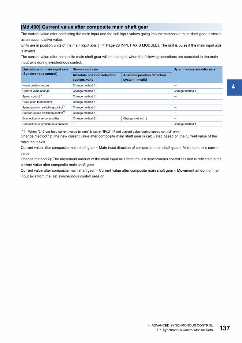
4
[Md.400] Current value after composite main shaft gearThe current value after combining the main input and the sub input values going into the composite main shaft gear is stored
as an accumulative value.
Units are in position units of the main input axis (Page 28 INPUT AXIS MODULE). The unit is pulse if the main input axis
is invalid.
The current value after composite main shaft gear will be changed when the following operations are executed in the main
input axis during synchronous control.
*1 When "2: Clear feed current value to zero" is set in "[Pr.21] Feed current value during speed control" only.
Change method 1): The new current value after composite main shaft gear is calculated based on the current value of the
main input axis.
Current value after composite main shaft gear = Main input direction of composite main shaft gear Main input axis current
value
Change method 2): The movement amount of the main input axis from the last synchronous control session is reflected to the
current value after composite main shaft gear.
Current value after composite main shaft gear = Current value after composite main shaft gear Movement amount of main
input axis from the last synchronous control session
Operations of main input axis(Synchronous control)
Servo input axis Synchronous encoder axis
Absolute position detection system: valid
Absolute position detection system: invalid
Home position return Change method 1)
Current value change Change method 1) Change method 1)
Speed control*1 Change method 1)
Fixed-pitch feed control Change method 1)
Speed-position switching control*1 Change method 1)
Position-speed switching control*1 Change method 1)
Connection to servo amplifier Change method 2) Change method 1)
Connection to synchronous encoder Change method 1)
4 ADVANCED SYNCHRONOUS CONTROL4.7 Synchronous Control Monitor Data 137

13
[Md.401] Current value per cycle after main shaft gearThe input movement amount after the main shaft gear is stored within the range from 0 to (Cam axis length per cycle - 1). The
unit is in cam axis cycle units (Page 126 Units for the output axis).
The value is restored according to "[Pr.460] Setting method of current value per cycle after main shaft gear" when starting
synchronous control. (Page 143 Synchronous Control Initial Position)
[Md.402] Current value per cycle after auxiliary shaft gearThe input movement amount after the auxiliary shaft gear is stored within the range from 0 to (Cam axis length per cycle - 1).
The unit is in cam axis cycle units (Page 126 Units for the output axis).
The value is restored according to "[Pr.461] Setting method of current value per cycle after auxiliary shaft gear" when starting
synchronous control. (Page 143 Synchronous Control Initial Position)
[Md.406] Cam axis phase compensation amountThe phase compensation amount for the cam axis is stored with cam axis cycle units (Page 126 Units for the output axis).
The phase compensation amount after smoothing processing with " [Pr.445] Cam axis phase compensation time constant" is
stored.
[Md.407] Cam axis current value per cycleThe cam axis current value per cycle is stored within the range from 0 to (Cam axis length per cycle - 1).
The current value after cam axis phase compensation processing can be monitored. The unit is in cam axis cycle units
(Page 126 Units for the output axis).
The value is restored according to "[Pr.462] Cam axis position restoration object" when starting synchronous control.
(Page 143 Synchronous Control Initial Position)
[Md.408] Cam reference positionThe feed current value is stored as the cam reference position. The unit is in output axis position units (Page 126 Units for
the output axis). When the unit is in degrees, a range from 0 to 35999999 is used.
The value is restored according to "[Pr.462] Cam axis position restoration object" when starting synchronous control.
(Page 143 Synchronous Control Initial Position)
[Md.409] Cam axis feed current valueThe feed current value of the cam axis is stored. The value is the same as "[Md.20] Feed current value" during synchronous
control.
[Md.410] Execute cam No.The executing cam No. is stored.
When "[Pr.440] Cam No." is changed during synchronous control, this is updated when the controlling cam No. switches.
[Md.411] Execute cam stroke amountThe executing cam stroke amount is stored.
When "[Pr.441] Cam stroke amount" is changed during synchronous control, this is updated when the controlling cam stroke
amount switches.
[Md.412] Execute cam axis length per cycleThe executing cam axis length per cycle is stored.
When "[Pr.439] Cam axis length per cycle" is changed during synchronous control, this is updated when the controlling cam
axis length per cycle switches.
[Md.420] Main shaft clutch ON/OFF statusThe clutch ON/OFF status is stored.
84 ADVANCED SYNCHRONOUS CONTROL4.7 Synchronous Control Monitor Data

4
[Md.421] Main shaft clutch smoothing statusThe smoothing status of the clutch is stored. The status is updated by the clutch smoothing method as follows.
[Md.422] Main shaft clutch slippage (accumulative)The accumulative slippage amount with the slippage method is stored as a signed value.
The absolute value of the accumulative slippage increases to reach the slippage at clutch ON during clutch ON.
The absolute value of the accumulative slippage decreases to reach 0 during clutch OFF.
Monitoring of the accumulative slippage is used to check the smoothing progress with the slippage method.
[Md.423] Auxiliary shaft clutch ON/OFF statusThe clutch ON/OFF status is stored.
[Md.424] Auxiliary shaft clutch smoothing statusThe smoothing status of the clutch is stored. The status is updated by the clutch smoothing method as follows.
[Md.425] Auxiliary shaft clutch slippage (accumulative)The accumulative slippage amount with the slippage method is stored as a signed value.
The absolute value of the accumulative slippage increases to reach the slippage at clutch ON during clutch ON.
The absolute value of the accumulative slippage decreases to reach 0 during clutch OFF.
Monitoring of the accumulative slippage is used to check the smoothing progress with the slippage method.
Method Details
Time constant method The status is always "1: On clutch smoothing" during the clutch ON status. The status will be "0: Not on clutch
smoothing" when the clutch is turned OFF and smoothing is completed.
Slippage method The status is "1: On clutch smoothing" till the clutch accumulative slippage amount reaches the slippage at clutch ON
when the clutch is turned ON. The status will change to "0: Not on clutch smoothing" when the clutch accumulative
slippage amount reaches the slippage at clutch ON. The status is "1: On clutch smoothing" till the clutch accumulative
slippage amount reaches 0 when the clutch is turned OFF. The status will change to "0: Not on clutch smoothing" when
the clutch accumulative slippage amount reaches 0.
4 ADVANCED SYNCHRONOUS CONTROL4.7 Synchronous Control Monitor Data 139
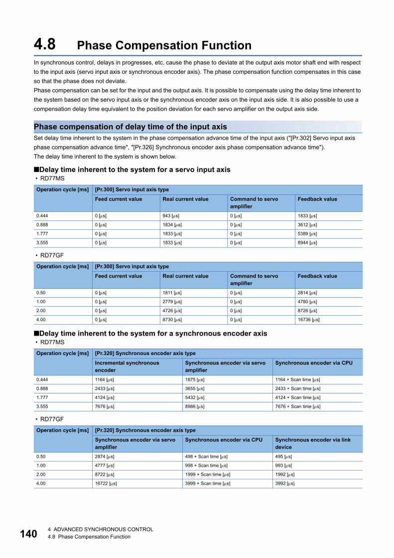
14
4.8 Phase Compensation FunctionIn synchronous control, delays in progresses, etc. cause the phase to deviate at the output axis motor shaft end with respect
to the input axis (servo input axis or synchronous encoder axis). The phase compensation function compensates in this case
so that the phase does not deviate.
Phase compensation can be set for the input and the output axis. It is possible to compensate using the delay time inherent to
the system based on the servo input axis or the synchronous encoder axis on the input axis side. It is also possible to use a
compensation delay time equivalent to the position deviation for each servo amplifier on the output axis side.
Phase compensation of delay time of the input axisSet delay time inherent to the system in the phase compensation advance time of the input axis ("[Pr.302] Servo input axis
phase compensation advance time", "[Pr.326] Synchronous encoder axis phase compensation advance time").
The delay time inherent to the system is shown below.
■Delay time inherent to the system for a servo input axis • RD77MS
• RD77GF
■Delay time inherent to the system for a synchronous encoder axis • RD77MS
• RD77GF
Operation cycle [ms] [Pr.300] Servo input axis type
Feed current value Real current value Command to servo amplifier
Feedback value
0.444 0 [s] 943 [s] 0 [s] 1833 [s]
0.888 0 [s] 1834 [s] 0 [s] 3612 [s]
1.777 0 [s] 1833 [s] 0 [s] 5389 [s]
3.555 0 [s] 1833 [s] 0 [s] 8944 [s]
Operation cycle [ms] [Pr.300] Servo input axis type
Feed current value Real current value Command to servo amplifier
Feedback value
0.50 0 [s] 1811 [s] 0 [s] 2814 [s]
1.00 0 [s] 2779 [s] 0 [s] 4780 [s]
2.00 0 [s] 4726 [s] 0 [s] 8726 [s]
4.00 0 [s] 8730 [s] 0 [s] 16736 [s]
Operation cycle [ms] [Pr.320] Synchronous encoder axis type
Incremental synchronous encoder
Synchronous encoder via servo amplifier
Synchronous encoder via CPU
0.444 1164 [s] 1875 [s] 1164 + Scan time [s]
0.888 2433 [s] 3655 [s] 2433 + Scan time [s]
1.777 4124 [s] 5432 [s] 4124 + Scan time [s]
3.555 7676 [s] 8986 [s] 7676 + Scan time [s]
Operation cycle [ms] [Pr.320] Synchronous encoder axis type
Synchronous encoder via servo amplifier
Synchronous encoder via CPU Synchronous encoder via link device
0.50 2874 [s] 498 + Scan time [s] 495 [s]
1.00 4777 [s] 998 + Scan time [s] 993 [s]
2.00 8722 [s] 1999 + Scan time [s] 1992 [s]
4.00 16722 [s] 3999 + Scan time [s] 3992 [s]
04 ADVANCED SYNCHRONOUS CONTROL4.8 Phase Compensation Function
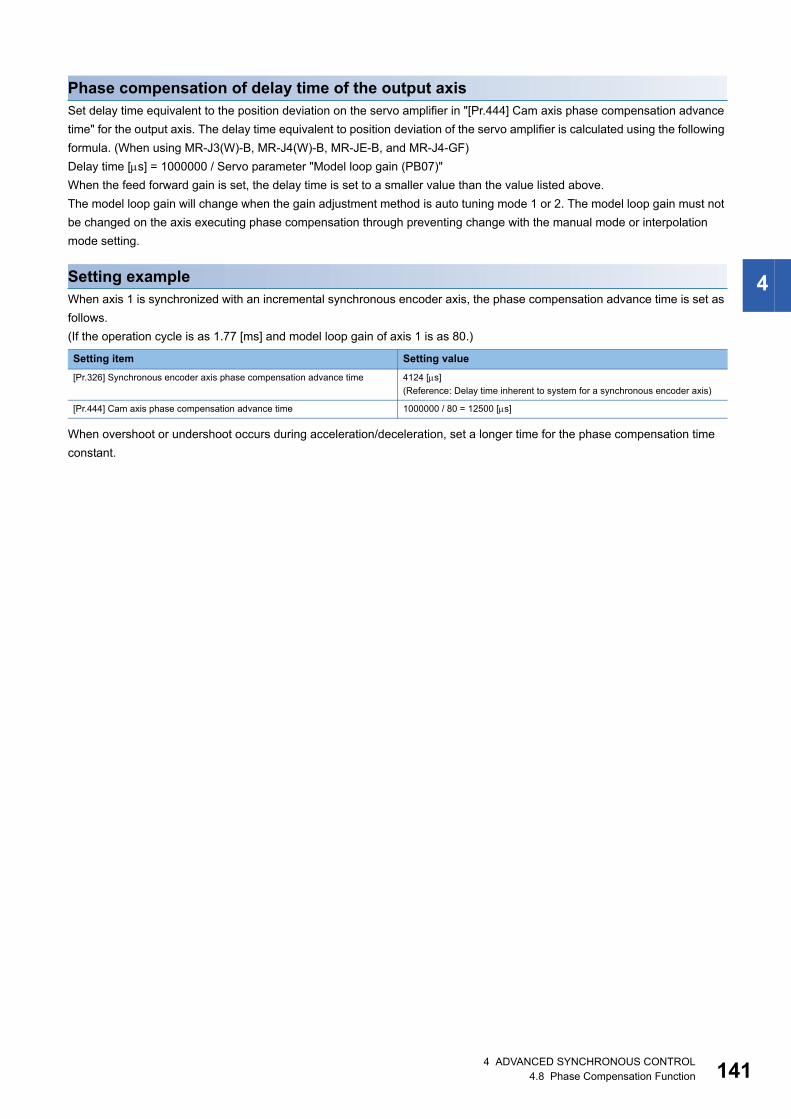
4
Phase compensation of delay time of the output axisSet delay time equivalent to the position deviation on the servo amplifier in "[Pr.444] Cam axis phase compensation advance
time" for the output axis. The delay time equivalent to position deviation of the servo amplifier is calculated using the following
formula. (When using MR-J3(W)-B, MR-J4(W)-B, MR-JE-B, and MR-J4-GF)
Delay time [s] = 1000000 / Servo parameter "Model loop gain (PB07)"
When the feed forward gain is set, the delay time is set to a smaller value than the value listed above.
The model loop gain will change when the gain adjustment method is auto tuning mode 1 or 2. The model loop gain must not
be changed on the axis executing phase compensation through preventing change with the manual mode or interpolation
mode setting.
Setting exampleWhen axis 1 is synchronized with an incremental synchronous encoder axis, the phase compensation advance time is set as
follows.
(If the operation cycle is as 1.77 [ms] and model loop gain of axis 1 is as 80.)
When overshoot or undershoot occurs during acceleration/deceleration, set a longer time for the phase compensation time
constant.
Setting item Setting value
[Pr.326] Synchronous encoder axis phase compensation advance time 4124 [s]
(Reference: Delay time inherent to system for a synchronous encoder axis)
[Pr.444] Cam axis phase compensation advance time 1000000 / 80 = 12500 [s]
4 ADVANCED SYNCHRONOUS CONTROL4.8 Phase Compensation Function 141

14
4.9 Output Axis Sub FunctionsThe following shows which sub functions apply for the output axis in synchronous control.
: Valid, : Invalid
Sub functions for an input axis in synchronous control conform to the specification of each control (Home
position return control, Positioning control, Manual control, Speed torque control). Refer to the following for
details.
MELSEC iQ-R Simple Motion Module User's Manual (Application)
Sub function Output axis
Details
Backlash compensation function The same control as other methods.
Electronic gear function
Speed limit function Setting is ignored.
("[Pr.8] Speed limit value" must be set to use "[Pr.446] Synchronous control deceleration time".)
Torque limit function Controlled with "[Pr.17] Torque limit setting value" or "[Cd.101] Torque output setting value" similar to
other methods.
Software stroke limit function The axis stops immediately when exceeding the software stroke limit range.
To disable the software stroke limit, set the setting value so that "Upper limit value = Lower limit value".
Hardware stroke limit function Controlled the same as positioning control.
Forced stop function Same control as other methods.
Speed change function Setting is ignored.
Override function
Acceleration/deceleration time change
function
Torque change function Same control as other methods.
Absolute system
Step function Setting is ignored.
Skip function
M code output function M code is not able to output.
Teaching function Same control as other methods.
Target position change function Setting is ignored.
Command in-position function
Acceleration/deceleration processing
function
Valid at deceleration stop only.
Deceleration time is set in "[Pr.446] Synchronous control deceleration time".
Pre-reading start function Setting is ignored.
Deceleration start flag function
Stop command processing for
deceleration stop function
Speed control 10 x multiplier setting for
degree axis function
Reflected on monitor data.
Operation setting for incompletion of
home position return function
Controlled the same as positioning control.
For a system that needs alignment, start synchronous control after establishing an a home position.
Servo ON/OFF Servo OFF request is ignored during synchronous control s imilar to positioning control.
24 ADVANCED SYNCHRONOUS CONTROL4.9 Output Axis Sub Functions

5
5 ADVANCED SYNCHRONOUS CONTROL INITIAL POSITION
The initial position for synchronous control is explained in this chapter.
Configure these settings for situations that require initial position alignment for synchronous control.
5.1 Synchronous Control Initial PositionThe following synchronous control monitor data can be aligned to a set position when starting synchronous control, as the
initial position for synchronous control.
The alignment to a synchronous control initial position is useful for restoring a system based on the last control status along
with restarting synchronous control after canceling midway.
Synchronous control monitor data The position when starting synchronous control
[Md.400] Current value after composite main shaft gear Restored to a position based on the main input axis of the main shaft.
[Md.401] Current value per cycle after main shaft gear Restored according to "[Pr.460] Setting method of current value per cycle after
main shaft gear".
[Md.402] Current value per cycle after auxiliary shaft gear Restored according to "[Pr.461] Setting method of current value per cycle after
auxiliary shaft gear".
[Md.407] Cam axis current value per cycle Restored according to "[Pr.462] Cam axis position restoration object".
[Md.408] Cam reference position
[Md.409] Cam axis feed current value
[Pr.462] Cam axis position restoration object0: Cam axis current value
per cycle restoration1: Cam reference position
restoration2: Cam axis feed current value
restoration
Composite main
shaft gearMain shaftgear
Main shaftsub input axis
Main shaftmain input axis
Output axis
Auxiliary shaftgear
Compositeauxiliary shaftgear
Auxiliary shaftclutch
Auxiliaryshaft axis
0: Previous value1: Initial setting value of
current value per cycle after auxiliary shaft gear
2: Calculate from input axis
[Md.400] Current value after composite main shaft gear
[Md.402] Current value per cycle after auxiliary shaft gear
[Pr.461] Setting method of current value per cycle after auxiliary shaft gear
[Md.407] Cam axis current value per cycle
[Md.408] Cam reference position
[Md.409] Cam axis feed current value
0: Previous value
2: Calculate from input axis
Main shaft clutch 1: Initial setting value of current value per cycle after main shaft gear
[Md.401] Current value per cycle after main shaft gear
[Pr.460] Setting method of current value per cycle after main shaft gear
5 ADVANCED SYNCHRONOUS CONTROL INITIAL POSITION5.1 Synchronous Control Initial Position 143

14
Current value after composite main shaft gear at synchronous control startThe current value after composite main shaft gear is restored as follows according to the main input axis operation executed
before starting synchronous control.
*1 When "[Pr.300] Servo input axis type" is either "1: Feed current value" or "2: Real current value", and when "[Pr.21] Feed current value during speed control" is "2: Clear feed current value to zero" only.
Restoration method 1): The new current value after composite main shaft gear is calculated based on the current value of the
main input axis.
Current value after composite main shaft gear =
Main input direction of composite main shaft gear Main input axis current value
Restoration method 2): The movement amount of the main input axis from the last synchronous control session is reflected to
the current value after composite main shaft gear.
Current value after composite main shaft gear =
Current value after composite main shaft gear at the last synchronous control session + Main input direction of composite
main shaft gear Amount of change of main input axis current value from the last synchronous control session
The current value after composite main shaft gear at the last synchronous control session is restored when "0: Invalid" is set
in "[Pr.400] Main input axis No.", or when a servo input axis or a synchronous encoder axis as the main input axis is not
connected.
"The last synchronous control session" indicates status just before the last synchronous control session was
stopped as follows. These are listed with the last synchronization status.
• Just before "[Cd.380] Synchronous control start" turns from ON to OFF.
• Just before deceleration stop by a stop command or an error, etc.
• Just before the system's power supply turned OFF to the Simple Motion module.
Operation of main input axis(Before synchronous control start)
Servo input axis Synchronous encoder axis
Absolute position detection system valid
Absolute position detection system invalid
Home position return Restoration method 1)
Current value change Restoration method 1) Restoration method 1)
Speed control*1 Restoration method 1)
Fixed-pitch feed control Restoration method 1)
Speed-position switching control*1 Restoration method 1)
Position-speed switching control*1 Restoration method 1)
Connection to servo amplifier Restoration method 2) Restoration method 1)
Connection to synchronous encoder Restoration method 1)
Others Restoration method 2) Restoration method 2)
45 ADVANCED SYNCHRONOUS CONTROL INITIAL POSITION5.1 Synchronous Control Initial Position

5
Current value per cycle after main/auxiliary shaft gear at synchronous control startThe current value per cycle after main shaft gear/current value per cycle after auxiliary shaft gear is restored as follows
according to the main input axis/auxiliary shaft operation executed before starting synchronous control.
*1 When "[Pr.300] Servo input axis type" is either "1: Feed current value" or "2: Real current value", and when "[Pr.21] Feed current value during speed control" is "2: Clear feed current value to zero" only.
Restoration method 1): The new value of the current value per cycle after main shaft gear/current value per cycle after
auxiliary shaft gear is calculated based on the current value after composite main shaft gear/auxiliary shaft current value.
[Main shaft]
Current value per cycle after main shaft gear = Main shaft gear ratio Current value after composite main shaft gear
[Auxiliary shaft]
Current value per cycle after auxiliary shaft gear = Auxiliary shaft gear ratio Auxiliary shaft current value
Restoration method 2): The movement amount from the last synchronous control session is reflected to the current value per
cycle after main shaft gear/current value per cycle after auxiliary shaft gear.
[Main shaft]
Current value per cycle after main shaft gear =
Current value per cycle after main shaft gear at the last synchronous control session + Main shaft gear ratio Amount of
change of current value after composite main shaft gear from the last synchronous control session
[Auxiliary shaft]
Current value per cycle after auxiliary shaft gear =
Current value per cycle after auxiliary shaft gear at the last synchronous control session + Auxiliary shaft gear ratio Amount
of change of auxiliary shaft current value from the last synchronous control session
The current value per cycle after main shaft gear/current value per cycle after auxiliary shaft gear at the last synchronous
control session is restored when "0: Invalid" is set in "[Pr.400] Main input axis No."/"[Pr.418] Auxiliary shaft axis No.", or when
a servo input axis or a synchronous encoder axis as the main input axis/auxiliary shaft is not connected.
Operation of main input axis/auxiliary shaft(Before synchronous controlstart)
Servo input axis Synchronous encoder axis
Absolute position detection system valid
Absolute position detection system invalid
Home position return Restoration method 1)
Current value change Restoration method 1) Restoration method 1)
Speed control*1 Restoration method 1)
Fixed-pitch feed control Restoration method 1)
Speed-position switching control*1 Restoration method 1)
Position-speed switching control*1 Restoration method 1)
Connection to servo amplifier Restoration method 2) Restoration method 1)
Connection to synchronous encoder Restoration method 1)
Others Restoration method 2) Restoration method 2)
5 ADVANCED SYNCHRONOUS CONTROL INITIAL POSITION5.1 Synchronous Control Initial Position 145

14
Cam axis position at synchronous control startThe cam axis position is composed of the relationship of 3 positions "Cam axis current value per cycle", "Cam reference
position" and "Cam axis feed current value". One of positions can be restored by defining 2 positions when starting
synchronous control.
Select from 3 objects as follows in "[Pr.462] Cam axis position restoration object" which position is to be restored.
(Refer to Page 150 Cam Axis Position Restoration Method for details on the restoration method.)
• Cam axis current value per cycle restoration
• Cam reference position restoration
• Cam axis feed current value restoration
Various parameters need to be set for the cam axis position restoration as shown below. (Refer to Page 147
Synchronous Control Initial Position Parameters for the setting details.)
: Required, : Required for initial setting value, : Not required
[Pr.462]Cam axis position restoration object
[Pr.463]Setting method of cam reference position
[Pr.467]Cam reference position (Initial setting)
[Pr.464]Setting method of cam axis current value per cycle
[Pr.468]Cam axis current value per cycle (Initial setting)
Restoration processing details
0: Cam axis current value per
cycle restoration
(Used as
search starting
point)
Restore "Cam axis current value per cycle"
based on "Cam reference position" and "Cam
axis feed current value".
1: Cam reference position
restoration
Restore "Cam reference position" based on
"Cam axis current value per cycle" and "Cam
axis feed current value".
2: Cam axis feed current value
restoration
Restore "Cam axis feed current value" based
on "Cam axis current value per cycle" and "Cam
reference position".
Cam axis current value per cycle
Cam axis feed current value
Cam reference position
65 ADVANCED SYNCHRONOUS CONTROL INITIAL POSITION5.1 Synchronous Control Initial Position

5
5.2 Synchronous Control Initial Position Parametersn: Axis No. - 1 (n: Axis No. - 17 for axis 17 to axis 32)
*1 Cam axis cycle units (Page 126 Units for the output axis)*2 Output axis position units (Page 126 Units for the output axis)
Setting item Setting details Setting value Default value
Buffer memory address
Axis 1 to axis 16
Axis 17 to axis 32
[Pr.460]
Setting method of
current value per
cycle after main
shaft gear
• Select the setting method for the current
value per cycle after main shaft gear.
Fetch cycle: At start of synchronous control
■Set in decimal.
0: Previous value
1: Initial setting value of current value
per cycle after main shaft gear
([Pr.465])
2: Calculate from input axis
0 36500+200n 1036500+200n
[Pr.461]
Setting method of
current value per
cycle after auxiliary
shaft gear
• Select the setting method for the current
value per cycle after auxiliary shaft gear.
Fetch cycle: At start of synchronous control
■Set in decimal.
0: Previous value
1: Initial setting value of current value
per cycle after auxiliary shaft gear
([Pr.466])
2: Calculate from input axis
0 36501+200n 1036501+200n
[Pr.462]
Cam axis position
restoration object
• Select the object to restore the cam axis
position.
Fetch cycle: At start of synchronous control
■Set in decimal.
0: Cam axis current value per cycle
restoration
1: Cam reference position restoration
2: Cam axis feed current value
restoration
0 36502+200n 1036502+200n
[Pr.463]
Setting method of
cam reference
position
• Select the setting method for the cam
reference position.
• Set for the cam axis current value per
cycle restoration or the cam axis feed
current value restoration
Fetch cycle: At start of synchronous control
■Set in decimal.
0: Previous value
1: Initial setting value of cam
reference position
2: Feed current value
2 36503+200n 1036503+200n
[Pr.464]
Setting method of
cam axis current
value per cycle
• Select the setting method for the cam axis
current value per cycle.
• Set for the cam reference position
restoration or the cam axis feed current
value restoration.
Fetch cycle: At start of synchronous control
■Set in decimal.
0: Previous value
1: Initial setting value of cam axis
current value per cycle
2: Current value per cycle after main
shaft gear
3: Current value per cycle after
auxiliary shaft gear
0 36504+200n 1036504+200n
[Pr.465]
Current value per
cycle after main
shaft gear (Initial
setting)
• Set the initial value of the current value per
cycle after main shaft gear.
Fetch cycle: At start of synchronous control
■Set in decimal.
0 to (Cam axis length per cycle - 1)
[Cam axis cycle units*1]
0 36506+200n
36507+200n
1036506+200n
1036507+200n
[Pr.466]
Current value per
cycle after auxiliary
shaft gear (Initial
setting)
• Set the initial value of the current value per
cycle after auxiliary shaft gear.
Fetch cycle: At start of synchronous control
■Set in decimal.
0 to (Cam axis length per cycle - 1)
[Cam axis cycle units*1]
0 36508+200n
36509+200n
1036508+200n
1036509+200n
[Pr.467]
Cam reference
position (Initial
setting)
• Set the initial value of the cam reference
position.
Fetch cycle: At start of synchronous control
■Set in decimal.
-2147483648 to 2147483647
[Output axis position units*2]
0 36510+200n
36511+200n
1036510+200n
1036511+200n
[Pr.468]
Cam axis current
value per cycle
(Initial setting)
• Set the initial value for the cam axis current
value per cycle.
• The restoration value for the cam axis
current value per cycle is searched from
the setting value with the cam axis current
value per cycle restoration.
Fetch cycle: At start of synchronous control
■Set in decimal.
0 to (Cam axis length per cycle - 1)
[Cam axis cycle units*1]
0 36512+200n
36513+200n
1036512+200n
1036513+200n
5 ADVANCED SYNCHRONOUS CONTROL INITIAL POSITION5.2 Synchronous Control Initial Position Parameters 147

14
[Pr.460] Setting method of current value per cycle after main shaft gearSelect the setting method of "[Md.401] Current value per cycle after main shaft gear" when starting synchronous control.
[Pr.461] Setting method of current value per cycle after auxiliary shaft gearSelect the setting method of "[Md.402] Current value per cycle after auxiliary shaft gear" when starting synchronous control.
[Pr.462] Cam axis position restoration objectSelect the object to be restored from "Cam axis current value per cycle", "Cam reference position" or "Cam axis feed current
value" when starting synchronous control.
[Pr.463] Setting method of cam reference positionSelect the method for the cam reference position to be restored when "[Pr.462] Cam axis position restoration object" is set to
"0: Cam axis current value per cycle restoration" or "2: Cam axis feed current value restoration".
[Pr.464] Setting method of cam axis current value per cycleSelect the method for the cam axis current value per cycle to be restored when "[Pr.462] Cam axis position restoration object"
is set to "1: Cam reference position restoration" or "2: Cam axis feed current value restoration".
Setting value Details
0: Previous value The current value per cycle after main shaft gear from the last synchronous control session is stored.
1: Initial setting value of current value per cycle
after main shaft gear
The value set in "[Pr.465] Current value per cycle after main shaft gear (Initial setting)" is stored.
2: Calculate from input axis The value calculated based on the current value after composite main shaft gear is stored.
Setting value Details
0: Previous value The current value per cycle after auxiliary shaft gear from the last synchronous control session is stored.
1: Initial setting value of current value per cycle
after auxiliary shaft gear
The value set in "[Pr.466] Current value per cycle after auxiliary shaft gear (Initial setting)" is stored.
2: Calculate from input axis The value calculated based on the auxiliary shaft current value is stored.
Setting value Details
0: Cam axis current value per cycle restoration Restore the cam axis current value per cycle from "Cam reference position" and "Cam axis feed current
value".
1: Cam reference position restoration Restore the cam reference position from "Cam axis current value per cycle" and "Cam axis feed current
value".
2: Cam axis feed current value restoration Restore the cam axis feed current value from "Cam axis current value per cycle" and "Cam reference
position".
Setting value Details
0: Previous value The cam reference position from the last synchronous control session is stored.
The feed current value is stored when the cam reference position from the last synchronous control session
is not saved.
1: Initial setting value of cam reference position The value set in "[Pr.467] Cam reference position (Initial setting)" is stored.
2: Feed current value The value set in "[Md.20] Feed current value" is stored.
Setting value Details
0: Previous value The cam axis current value per cycle from the last synchronous control session is stored as is.
1: Initial setting value of cam axis current value
per cycle
The value set in "[Pr.468] Cam axis current value per cycle (Initial setting)" is stored.
2: Current value per cycle after main shaft gear The current value per cycle after main shaft gear is stored.
3: Current value per cycle after auxiliary shaft
gear
The current value per cycle after auxiliary shaft gear is stored.
85 ADVANCED SYNCHRONOUS CONTROL INITIAL POSITION5.2 Synchronous Control Initial Position Parameters

5
[Pr.465] Current value per cycle after main shaft gear (Initial setting)Set the initial setting value of the current value per cycle after main shaft gear when "[Pr.460] Setting method of current value
per cycle after main shaft gear" is set to "1: Current value per cycle after main shaft gear (Initial setting)".
The unit settings are in cam axis cycle units (Page 126 Units for the output axis). Set within the range from 0 to (Cam axis
length per cycle - 1).
[Pr.466] Current value per cycle after auxiliary shaft gear (Initial setting)Set the initial setting value of the current value per cycle after auxiliary shaft gear when "[Pr.461] Setting method of current
value per cycle after auxiliary shaft gear" is set to "1: Current value per cycle after auxiliary shaft gear (Initial setting)".
The unit settings are in cam axis cycle units (Page 126 Units for the output axis). Set within the range from 0 to (Cam axis
length per cycle - 1).
[Pr.467] Cam reference position (Initial setting)Set the initial setting value of the cam reference position in output axis position units (Page 126 Units for the output axis)
when "[Pr.463] Setting method of cam reference position" is set to "1: Cam reference position (Initial setting)".
[Pr.468] Cam axis current value per cycle (Initial setting)Set a value according to the setting for "[Pr.462] Cam axis position restoration object".
The unit settings are in cam axis cycle units (Page 126 Units for the output axis). Set within the range from 0 to (Cam axis
length per cycle - 1).
[Pr.462]Cam axis position restoration object
Setting value
0: Cam axis current value per cycle restoration Set the starting point for search processing to restore the cam axis current value per cycle.
Set to restore the position on the return path in two-way cam pattern operation.
Refer to the following for details on search processing.
Page 150 Cam axis current value per cycle restoration
1: Cam reference position restoration Set the initial setting value for the cam axis current value per cycle when "[Pr.464] Setting method of cam
axis current value per cycle" is set to "1: Cam axis current value per cycle (Initial setting)".2: Cam axis feed current value restoration
5 ADVANCED SYNCHRONOUS CONTROL INITIAL POSITION5.2 Synchronous Control Initial Position Parameters 149

15
5.3 Cam Axis Position Restoration Method
Cam axis current value per cycle restorationIf "[Pr.462] Cam axis position restoration object" is set to "0: Cam axis current value per cycle restoration" when starting
synchronous control, the cam axis current value per cycle is restored based on the cam reference position and the cam axis
feed current value.
Select the method for the cam reference position to be restored. The feed current value when starting synchronous control is
used as the cam axis feed current value.
The cam axis current value per cycle is restored by searching for the corresponding value from the beginning to the end of the
cam pattern. Set the starting point from where to search the cam pattern in "[Pr.468] Cam axis current value per cycle (Initial
setting)". (It is also possible to search the return path in a two-way cam pattern operation.)
• With two-way cam pattern operation, if the corresponding cam axis current value per cycle is not found, the
error "Cam axis current value per cycle restoration disable" (error code: 1C28H) will occur and synchronous
control will not be started.
• When starting synchronous control, the feed current value may change slightly from its original position at
starting synchronous control. This is due to the readjustment of the position based on the restored cam axis
current value per cycle. This does not result in the position mismatch.
• With a feed operation cam pattern, if the corresponding cam axis current value per cycle is not found on the
first cycle, the cam reference position is changed automatically and the pattern is searched again.
• If the cam resolution is large, search processing may take a long time when starting synchronous control.
(Cam resolution 256: Up to 0.4 ms [RD77MS], Up to 0.5ms [RD77GF], Cam resolution 32768: Up to 26 ms)
0: Previous value1: Initial setting
value of cam reference position
2: Feed current value
Cam axis feed current value
Cam reference position
[Md.20] Feed current value (At synchronous control start)
[Pr.463] Setting method of cam reference position
[Md.409] Cam axis feed current value
[Md.408] Cam reference position
Cam axis current value per cycle
The cam axis current value per cycle is restored based on the cam reference position and cam axis feed current value.[Md.407] Cam axis current value per cycle
Search the cam pattern(It is also possible to search from the middle of the cam axis current value per cycle.)
05 ADVANCED SYNCHRONOUS CONTROL INITIAL POSITION5.3 Cam Axis Position Restoration Method

5
Cam axis current value per cycle restoration operation
■With a two-way cam pattern operation • Search from "Cam axis current value per cycle = 0". (Cam data starting point = 0)
• Search from a value in the middle of the cam axis current value per cycle. (Cam data starting point 0)
• Search from a value in the middle of the cam axis current value per cycle. (Cam data starting point 0)
• The search fails.
■With a feed operation cam pattern • Search from "Cam axis current value per cycle = 0". (Cam data starting point = 0)
Cam axis feed current value(Feed current value)
Cam reference position
Search from "Cam axis current value per cycle=0".
Restore to the first feed current value that matches. (Other values are not restored.)
Cam axis current value per cycle
[Pr.468] Cam axis current value per cycle (Initial setting)
Cam axis feed current value(Feed current value)
Cam reference position
Restore to the first feed current valuethat matches. (The restoration is done on the second.)
Search from the value in the middle. (Preceding values are searched later.)
Cam axis current value per cycle
Cam axis feed current value(Feed current value)
Cam reference positionRestore to the first feed current valuethat matches.
Cam datastarting point
[Pr.468] Cam axis current value per cycle (Initial setting)
Search from the value in the middle.
Cam axis current value per cycle
Cam axis feed current value(Feed current value)
Cam reference position
Restoration fails. No matchis found for the feedcurrent value within 1 cycle.
Cam axis current value per cycle
Cam axis feed current value(Feed current value)
Cam reference position
Search from "Cam axis current value per cycle=0".
Restore to the first feed current value that matches. (Other values are not restored.)
Cam axis current value per cycle
5 ADVANCED SYNCHRONOUS CONTROL INITIAL POSITION5.3 Cam Axis Position Restoration Method 151
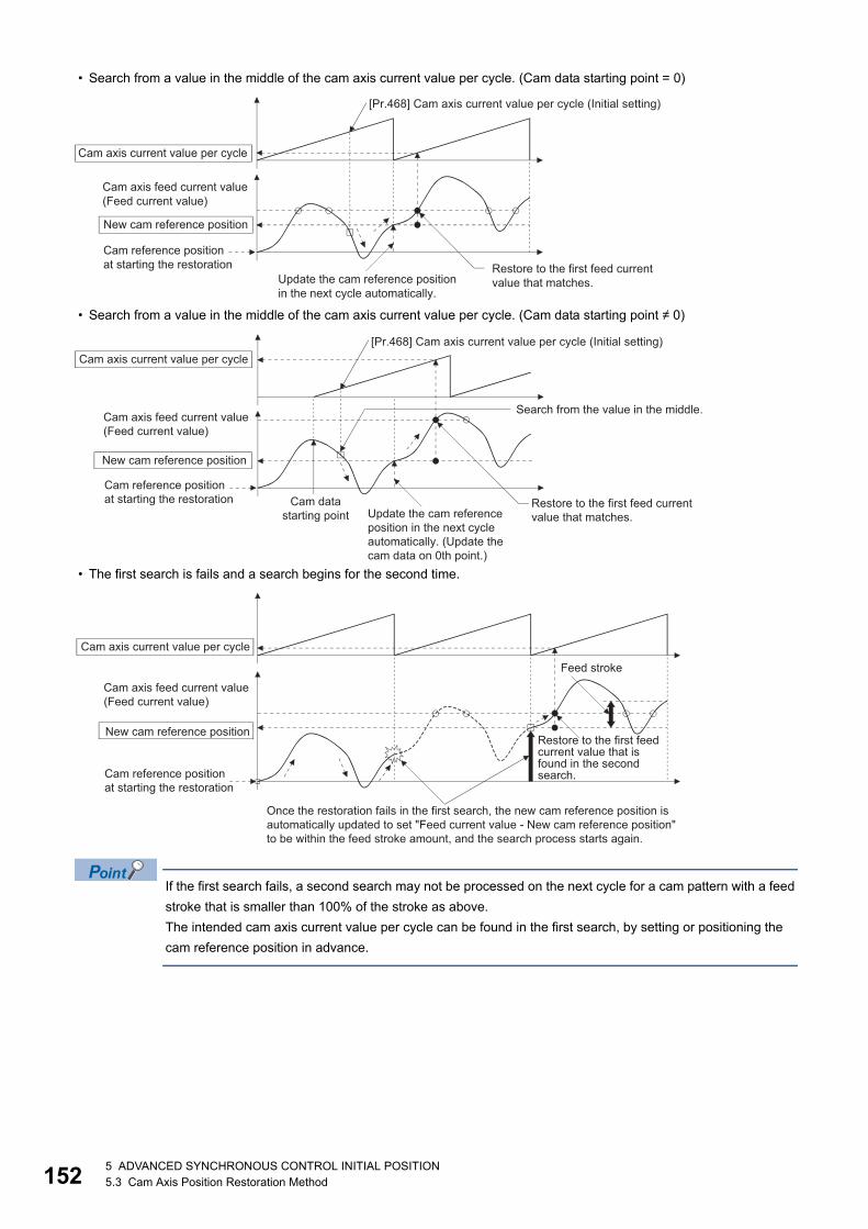
15
• Search from a value in the middle of the cam axis current value per cycle. (Cam data starting point = 0)
• Search from a value in the middle of the cam axis current value per cycle. (Cam data starting point 0)
• The first search is fails and a search begins for the second time.
If the first search fails, a second search may not be processed on the next cycle for a cam pattern with a feed
stroke that is smaller than 100% of the stroke as above.
The intended cam axis current value per cycle can be found in the first search, by setting or positioning the
cam reference position in advance.
[Pr.468] Cam axis current value per cycle (Initial setting)
Cam axis feed current value(Feed current value)
Cam reference positionat starting the restoration
Update the cam reference positionin the next cycle automatically.
Cam axis current value per cycle
Restore to the first feed current value that matches.
New cam reference position
[Pr.468] Cam axis current value per cycle (Initial setting)
Cam axis feed current value(Feed current value)
Update the cam reference position in the next cycleautomatically. (Update the cam data on 0th point.)
Cam reference positionat starting the restoration
Search from the value in the middle.
Cam datastarting point
Cam axis current value per cycle
New cam reference position
Restore to the first feed current value that matches.
Cam axis feed current value(Feed current value)
Restore to the first feedcurrent value that is found in the second search.Cam reference position
at starting the restoration
Once the restoration fails in the first search, the new cam reference position is automatically updated to set "Feed current value - New cam reference position" to be within the feed stroke amount, and the search process starts again.
Feed stroke
Cam axis current value per cycle
New cam reference position
25 ADVANCED SYNCHRONOUS CONTROL INITIAL POSITION5.3 Cam Axis Position Restoration Method
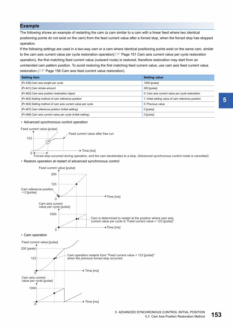
5
ExampleThe following shows an example of restarting the cam (a cam similar to a cam with a linear feed where two identical
positioning points do not exist on the cam) from the feed current value after a forced stop, when the forced stop has stopped
operation.
If the following settings are used in a two-way cam or a cam where identical positioning points exist on the same cam, similar
to the cam axis current value per cycle restoration operation(Page 151 Cam axis current value per cycle restoration
operation), the first matching feed current value (outward route) is restored, therefore restoration may start from an
unintended cam pattern position. To avoid restoring the first matching feed current value, use cam axis feed current value
restoration (Page 156 Cam axis feed current value restoration).
• Advanced synchronous control operation
• Restore operation at restart of advanced synchronous control
• Cam operation
Setting item Setting value
[Pr.439] Cam axis length per cycle 1000 [pulse]
[Pr.441] Cam stroke amount 200 [pulse]
[Pr.462] Cam axis position restoration object 0: Cam axis current value per cycle restoration
[Pr.463] Setting method of cam reference position 1: Initial setting value of cam reference position
[Pr.464] Setting method of cam axis current value per cycle 0: Previous value
[Pr.467] Cam reference position (Initial setting) 0 [pulse]
[Pr.468] Cam axis current value per cycle (Initial setting) 0 [pulse]
Feed current value [pulse]Feed current value after free run
Forced stop occurred during operation, and the cam decelerates to a stop. (Advanced synchronous control mode is cancelled)
Time [ms]0
123
Feed current value [pulse]
Cam axis currentvalue per cycle [pulse]
Cam reference position = 0 [pulse]
Cam is determined to restart at the position where cam axis current value per cycle is "Feed current value = 123 [pulse]".
Time [ms]
Time [ms]
0
123
1000
200
0
Feed current value [pulse]
Cam operation restarts from "Feed current value = 123 [pulse]"when the previous forced stop occurred.
Cam axis currentvalue per cycle [pulse]
200 (peak)
Time [ms]
Time [ms]
123
1000
0
0
5 ADVANCED SYNCHRONOUS CONTROL INITIAL POSITION5.3 Cam Axis Position Restoration Method 153

15
Cam reference position restorationIf "[Pr.462] Cam axis position restoration object" is set to "1: cam reference position restoration" when starting synchronous
control, the cam reference position is restored based on the cam axis current value per cycle and the cam axis feed current
value.
Select the method for the cam axis current value per cycle to be restored. The feed current value when starting synchronous
control is used as the cam axis feed current value.
ExampleThe following shows an example of starting operation from a position of "cam axis current value per cycle=0" by restoring the
cam reference position when starting from "feed current value=0 [pulse]", in the cam when the cam data starting point is not 0.
• Operation before starting advanced synchronous control
Setting item Setting value
[Pr.439] Cam axis length per cycle 1000 [pulse]
[Pr.441] Cam stroke amount 200 [pulse]
[Pr.462] Cam axis position restoration object 1: Cam reference position restoration
[Pr.463] Setting method of cam reference position None
[Pr.464] Setting method of cam axis current value per cycle 1: Initial setting value of cam axis current value per cycle
[Pr.467] Cam reference position (Initial setting) None
[Pr.468] Cam axis current value per cycle (Initial setting) 0 [pulse]
The cam reference position is restoredbased on the cam axis current value percycle and the cam axis feed current value.
[Md.20] Feed current value(At synchronous control start)
Cam axis feed current value
Cam axis current value per cycle
Restored by the equation of "Feed current value - Cam axis current value per cycle"
[Md.407] Cam axis current value per cycle
[Md.409] Cam axis feed current value
[Pr.464] Setting method of cam axis current value per cycle
0: Previous value1: Initial setting value of cam axis
current value per cycle2: Current value per cycle
after main shaft gear3: Current value per cycle
after auxiliary shaft gear [Md.408] Cam reference position
Cam reference position
Feed current value [pulse]
"Feed current value = 0" due tohome position return, etc.
Cam pattern for "cam datastarting point setting = 200 [pulse]"
Stroke ratio [%]
Time [ms] Cam axis length per cycle [pulse]0 1000
100(200 [pulse])
0
45 ADVANCED SYNCHRONOUS CONTROL INITIAL POSITION5.3 Cam Axis Position Restoration Method

5
• Restore operation at start of advanced synchronous control
• Cam operation
Feed current value [pulse]
Time [ms]
Time [ms]
Cam starting point is set to"feed current value = 0 [pulse]".
The estimated cam pattern for"Cam axis current value per cycle = 0" as the origin is determined.
Cam reference position becomes "0 - 200 = -200 [pulse]".
Cam axis currentvalue per cycle [pulse]
Cam axis length per cycle = 0 [pulse]
1000
0
0
Feed current value [pulse]Cam operation starts from 0 point which is now"Cam reference position = -200 [pulse]".
Time [ms]
Time [ms]
Cam axis currentvalue per cycle [pulse]
1000
-200
0
0
5 ADVANCED SYNCHRONOUS CONTROL INITIAL POSITION5.3 Cam Axis Position Restoration Method 155
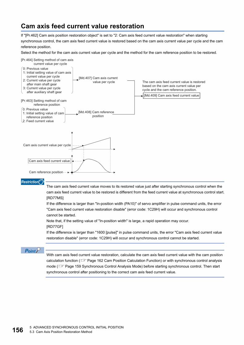
15
Cam axis feed current value restorationIf "[Pr.462] Cam axis position restoration object" is set to "2: Cam axis feed current value restoration" when starting
synchronous control, the cam axis feed current value is restored based on the cam axis current value per cycle and the cam
reference position.
Select the method for the cam axis current value per cycle and the method for the cam reference position to be restored.
The cam axis feed current value moves to its restored value just after starting synchronous control when the
cam axis feed current value to be restored is different from the feed current value at synchronous control start.
[RD77MS]
If the difference is larger than "In-position width (PA10)" of servo amplifier in pulse command units, the error
"Cam axis feed current value restoration disable" (error code: 1C29H) will occur and synchronous control
cannot be started.
Note that, if the setting value of "In-position width" is large, a rapid operation may occur.
[RD77GF]
If the difference is larger than "1600 [pulse]" in pulse command units, the error "Cam axis feed current value
restoration disable" (error code: 1C29H) will occur and synchronous control cannot be started.
With cam axis feed current value restoration, calculate the cam axis feed current value with the cam position
calculation function (Page 162 Cam Position Calculation Function) or with synchronous control analysis
mode (Page 159 Synchronous Control Analysis Mode) before starting synchronous control. Then start
synchronous control after positioning to the correct cam axis feed current value.
The cam axis feed current value is restored based on the cam axis current value per cycle and the cam reference position.
Cam reference position
[Md.407] Cam axis current value per cycle
0: Previous value1: Initial setting value of cam axis
current value per cycle2: Current value per cycle
after main shaft gear3: Current value per cycle
after auxiliary shaft gear
0: Previous value1: Initial setting value of cam
reference position2: Feed current value
[Md.409] Cam axis feed current value
[Md.408] Cam reference position
Cam axis current value per cycle
Cam axis feed current value
[Pr.464] Setting method of cam axis current value per cycle
[Pr.463] Setting method of camreference position
65 ADVANCED SYNCHRONOUS CONTROL INITIAL POSITION5.3 Cam Axis Position Restoration Method
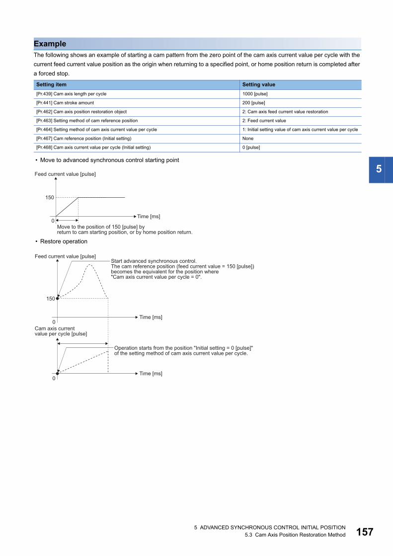
5
ExampleThe following shows an example of starting a cam pattern from the zero point of the cam axis current value per cycle with the
current feed current value position as the origin when returning to a specified point, or home position return is completed after
a forced stop.
• Move to advanced synchronous control starting point
• Restore operation
Setting item Setting value
[Pr.439] Cam axis length per cycle 1000 [pulse]
[Pr.441] Cam stroke amount 200 [pulse]
[Pr.462] Cam axis position restoration object 2: Cam axis feed current value restoration
[Pr.463] Setting method of cam reference position 2: Feed current value
[Pr.464] Setting method of cam axis current value per cycle 1: Initial setting value of cam axis current value per cycle
[Pr.467] Cam reference position (Initial setting) None
[Pr.468] Cam axis current value per cycle (Initial setting) 0 [pulse]
Feed current value [pulse]
Time [ms]
Move to the position of 150 [pulse] byreturn to cam starting position, or by home position return.
0
150
Feed current value [pulse]
Time [ms]
Time [ms]
Cam axis currentvalue per cycle [pulse]
Start advanced synchronous control.The cam reference position (feed current value = 150 [pulse])becomes the equivalent for the position where"Cam axis current value per cycle = 0".
Operation starts from the position "Initial setting = 0 [pulse]"of the setting method of cam axis current value per cycle.
0
150
0
5 ADVANCED SYNCHRONOUS CONTROL INITIAL POSITION5.3 Cam Axis Position Restoration Method 157

15
• Cam operation
Feed current value [pulse]
The time when cam axis current value per cycle is "0 [pulse]"Cam axis currentvalue per cycle [pulse]
With the "feed current value = 150 [pulse]"position as the start point, the cam operatesfor the amount of "Cam reference position + cam stroke amount".
Time [ms]
Time [ms]
0
150
1000
350
0
85 ADVANCED SYNCHRONOUS CONTROL INITIAL POSITION5.3 Cam Axis Position Restoration Method
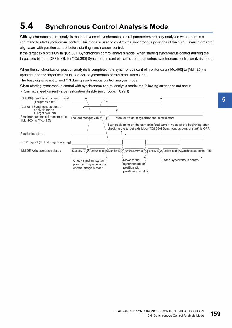
5
5.4 Synchronous Control Analysis ModeWith synchronous control analysis mode, advanced synchronous control parameters are only analyzed when there is a
command to start synchronous control. This mode is used to confirm the synchronous positions of the output axes in order to
align axes with position control before starting synchronous control.
If the target axis bit is ON in "[Cd.381] Synchronous control analysis mode" when starting synchronous control (turning the
target axis bit from OFF to ON for "[Cd.380] Synchronous control start"), operation enters synchronous control analysis mode.
When the synchronization position analysis is completed, the synchronous control monitor data ([Md.400] to [Md.425]) is
updated, and the target axis bit in "[Cd.380] Synchronous control start" turns OFF.
The busy signal is not turned ON during synchronous control analysis mode.
When starting synchronous control with synchronous control analysis mode, the following error does not occur.
• Cam axis feed current value restoration disable (error code: 1C29H)
Synchronous control monitor data([Md.400] to [Md.425])
Standby (0) Analyzing (5)
Positioning start
Monitor value at synchronous control start
Check synchronization position in synchronous control analysis mode.
Move to the synchronization position with positioning control.
Start synchronous control
The last monitor value
Standby (0) Standby (0) Analyzing (5) Synchronous control (15)Position control (8)
[Cd.380] Synchronous control start (Target axis bit)
[Cd.381] Synchronous control analysis mode (Target axis bit)
[Md.26] Axis operation status
BUSY signal (OFF during analyzing)
Start positioning on the cam axis feed current value at the beginning after checking the target axis bit of "[Cd.380] Synchronous control start" is OFF.
5 ADVANCED SYNCHRONOUS CONTROL INITIAL POSITION5.4 Synchronous Control Analysis Mode 159

16
Synchronous control system control data
*1 The range from axis 1 to 2 is valid in the 2-axis module, from axis 1 to 4 is valid in the 4-axis module, from axis 1 to 8 is valid in the 8-axis module, from axis 1 to 16 is valid in the 16-axis module, and from axis 1 to 32 is valid in the 32-axis module.
Setting item
Setting details Setting value Default value
Buffer memory address
Axis 1 to axis 16
Axis 17 to axis 32
[Cd.380]
Synchronous
control start
• Synchronous control begins if the target axis
bit is turned ON.
• Synchronous control ends if the bit is turned
OFF during synchronous control.
Fetch cycle: Operation cycle
■Set the target axis in bit.
Set with the following two buffer memory
addresses.
• Buffer memory address: 36320
(bit0: axis 1 to bit15: axis 16*1)
• Buffer memory address: 1036320
(bit0: axis 17 to bit15: axis 32*1)
OFF: Synchronous control end
ON: Synchronous control start
0 36320 1036320
[Cd.381]
Synchronous
control
analysis mode
• If the target axis bit is turned ON and
synchronous control is started, the analysis
is only executed and the control does not
start.
Fetch cycle: At start of synchronous control
■Set the target axis in bit.
Set with the following two buffer memory
addresses.
• Buffer memory address:36322
(bit0: axis 1 to bit15: axis 16*1)
• Buffer memory address:1036322
(bit0: axis 17 to bit15: axis 32*1)
OFF: Synchronous control analysis mode OFF
ON: Synchronous control analysis mode ON
0 36322 1036322
b0b15 b12 b8 b4
b0b15 b12 b8 b4
Buffer memory address: 36320
Axis 1 to 16
Axis 17 to 32
Buffer memory address: 1036320
b0b15 b12 b8 b4
b0b15 b12 b8 b4
Buffer memory address: 36322
Axis 1 to 16
Axis 17 to 32
Buffer memory address: 1036322
05 ADVANCED SYNCHRONOUS CONTROL INITIAL POSITION5.4 Synchronous Control Analysis Mode

5
ExampleThe following shows a procedure of aligning the synchronous position of an output axis that references the input axis.
1. Set the following values in the synchronous control initial position parameters.
2. Turn ON the target axis bit of "[Cd.381] Synchronous control analysis mode", and then turn the target axis bit from OFF
to ON in "[Cd.380] Synchronous control start" to start the synchronous control analysis mode.
3. Verify the target axis bit is OFF for "[Cd.380] Synchronous control start", and execute positioning for the output axis to be
updated to "[Md.409] Cam axis feed current value".
4. Turn OFF the target axis bit of "[Cd.381] Synchronous control analysis mode", and then turn the target axis bit from OFF
to ON in "[Cd.380] Synchronous control start" to start synchronous control.
Setting item Setting value
[Pr.460] Setting method of current value per cycle after main shaft gear 2: Calculate from input axis
[Pr.462] Cam axis position restoration object 2: Cam axis feed current value restoration
[Pr.463] Setting method of cam reference position 0: Previous value
[Pr.464] Setting method of cam axis current value per cycle 2: Current value per cycle after main shaft gear
5 ADVANCED SYNCHRONOUS CONTROL INITIAL POSITION5.4 Synchronous Control Analysis Mode 161

16
5.5 Cam Position Calculation FunctionThe cam position is calculated by the program with this function. This function can be used to calculate the cam position for
the synchronous control initial position before starting synchronous control.
ExampleThe following shows the procedure for synchronous position alignment, in a synchronous system where cam axes 2 and 3 are
synchronized with the cam axis current value per cycle of axis 1.
1. Calculate the cam axis current value per cycle using this function based on the feed current value and the cam reference
position of axis 1.
2. Calculate the cam axis feed current value of axis 2 with this function based on the cam axis current value per cycle that
was calculated in 1).
3. Calculate the cam axis feed current value of axis 3 with this function based on the cam axis current value per cycle that
was calculated in 1).
4. Execute positioning on axis 2 to the cam axis feed current value which was calculated in 2), and also on axis 3 to the
cam axis feed current value which was calculated in 3).
5. Start synchronous control on axis 1, 2 and 3 with the feed current value restoration mode. Use the cam axis current value
per cycle that was calculated in 1) for the cam axis current value per cycle (Initial setting).
Cam position calculation control data
*1 With the exception of positioning control, main cycle processing is executed during the next available time. It changes by status of axis start.
*2 Output axis position units(Page 126 Units for the output axis)*3 Cam axis cycle units(Page 126 Units for the output axis)
Setting item Setting details Setting value Default value
Buffer memory address
[Cd.612]
Cam position
calculation request
• Set the cam position calculation request.
• The Simple Motion module resets the value to "0"
automatically after completion of the cam position
calculation.
Fetch cycle: Main cycle*1
■Set in decimal.
1: Cam axis feed current value calculation
request
2: Cam axis current value per cycle calculation
request
0 53780
[Cd.613]
Cam position
calculation: Cam No.
• Set the cam No. for the cam position calculation.
Fetch cycle: At requesting cam position calculation
■Set in decimal.
0 to 256 [RD77MS]
0 to 1024 [RD77GF]
0 53781
[Cd.614]
Cam position
calculation: Stroke
amount
• Set the cam stroke amount for the cam position
calculation.
Fetch cycle: At requesting cam position calculation
■Set in decimal.
-2147483648 to 2147483647
[Output axis position units*2]
0 53782
53783
[Cd.615]
Cam position
calculation: Cam axis
length per cycle
• Set the cam axis length per cycle for the cam position
calculation.
Fetch cycle: At requesting cam position calculation
■Set in decimal.
1 to 2147483647
[Cam axis cycle units*3]
0 53784
53785
[Cd.616]
Cam position
calculation: Cam
reference position
• Set the cam reference position for the cam position
calculation.
Fetch cycle: At requesting cam position calculation
■Set in decimal.
-2147483648 to 2147483647
[Output axis position units*2]
0 53786
53787
[Cd.617]
Cam position
calculation: Cam axis
current value per
cycle
• Set the cam axis current value per cycle for the cam
position calculation.
Fetch cycle: At requesting cam position calculation
■Set in decimal.
0 to (Cam axis length per cycle)
[Cam axis cycle units*3]
0 53788
53789
[Cd.618]
Cam position
calculation: Cam axis
feed current value
• Set the cam axis feed current value for the cam position
calculation. (Set when calculating the cam axis current
value per cycle.)
Fetch cycle: At requesting cam position calculation
■Set in decimal.
-2147483648 to 2147483647
[Output axis position units*2]
0 53790
53791
25 ADVANCED SYNCHRONOUS CONTROL INITIAL POSITION5.5 Cam Position Calculation Function
5
[Cd.612] Cam position calculation requestSet the following commands to calculate the cam position.
The result is stored in "[Md.600] Cam position calculation result" and the setting value is reset to "0" automatically after
completion of cam position calculation.
If warnings occur when requesting the cam position calculation, the warning No. is stored in "[Md.24] Axis warning No." of axis
1 and the setting value is reset to "0" automatically.
When a value other than the request command values listed above is set, this calculation does not get executed and the
setting value is reset to "0" automatically.
[Cd.613] Cam position calculation: Cam No.Set the cam No. for the cam position calculation. If 0 is set for the cam No., the cam position is calculated as a linear cam.
[Cd.614] Cam position calculation: Stroke amountSet the cam stroke amount for the cam position calculation.
[Cd.615] Cam position calculation: Cam axis length per cycleSet the cam axis length per cycle for the cam position calculation.
[Cd.616] Cam position calculation: Cam reference positionSet the cam reference position for the cam position calculation.
[Cd.617] Cam position calculation: Cam axis current value per cycleSet the cam axis current value per cycle for the cam position calculation when calculating the cam axis feed current value.
Set the cam axis current value per cycle as the starting point to search when calculating the cam axis current value per cycle
and the cam position.
[Cd.618] Cam position calculation: Cam axis feed current valueSet the cam axis feed current value for the cam position calculation when calculating the cam axis current value per cycle.
This is not used when calculating the cam axis feed current value.
Setting value
Details
1 Cam axis feed current value calculation request
2 Cam axis current value per cycle calculation request
5 ADVANCED SYNCHRONOUS CONTROL INITIAL POSITION5.5 Cam Position Calculation Function 163

16
Cam position calculation monitor data
*1 Output axis position units (Page 126 Units for the output axis)*2 Cam axis cycle units(Page 126 Units for the output axis)
[Md.600] Cam position calculation resultThe result of the cam position calculation is stored.
Search for the cam axis current value per cycleWhen calculating the cam axis current value per cycle using cam data, the position corresponding to "[Cd.618] Cam position
calculation: Cam axis feed current value" is searched using cam data based on the position specified by "[Cd.617] Cam
position calculation: Cam axis current value per cycle".
The following shows the order of the search for "[Cd.618] Cam position calculation: Cam axis feed current value".
Monitor item Storage details Monitor value Buffer memory address
[Md.600]
Cam position calculation result
• The result of the cam position calculation
is stored.
Refresh cycle: At cam position calculation
completion
■Monitoring is carried out in decimal.
• When calculating the cam axis feed
current value:
-2147483648 to 2147483647
[Output axis position units*1]
• When calculating the cam axis
current value per cycle:
0 to (Cam axis length per cycle - 1)
[Cam axis cycle units*2]
53800
53801
Cam position calculation Storage details
When calculating the cam axis feed
current value
Calculated value of the cam axis feed current value is stored.
When calculating the cam axis
current value per cycle
Calculated value of the cam axis current value per cycle is stored.
The cam reference position is not updated automatically by the cam position calculation function.
45 ADVANCED SYNCHRONOUS CONTROL INITIAL POSITION5.5 Cam Position Calculation Function

5
■Stroke ratio data formatWhen "the nth point of cam data [Cd.617] Cam position calculation: Cam axis current value per cycle < the n + 1st point of
cam data", the position corresponding to "[Cd.618] Cam position calculation: Cam axis feed current value" is searched from
the nth point of cam data.
If "[Cd.617] Cam position calculation: Cam axis current value per cycle" is in the middle of the cam data and the
corresponding position is not found until the last point of the cam data, return to the 0th point and search until the search
starting point.
If the corresponding position is not found even though the whole area of the cam data has been searched, the warning "Cam
position calculation cam axis 1 cycle current value calculation disable" (warning code: 0C64H) will occur in reciprocated cam
pattern.
For the feed cam, calculates "[Cd.618] Cam position calculation: Cam axis feed current value" by the stroke difference and
searches again from the 0th point to the whole range. If the corresponding position is not found even though the search
process starts again, the warning "Cam position calculation cam axis 1 cycle current value calculation disable" (warning code:
0C64H) will occur.
Ex.
When "[Cd.617] Cam position calculation: Cam axis current value per cycle" is corresponding to the 0th point of cam data
• Searches until between the 255th point and the 256th point (last point) in order of the cam data between the 0th point and
the 1st point and between the 1st point and the 2nd point.
Ex.
When "[Cd.617] Cam position calculation: Cam axis current value per cycle" is corresponding to the 128th point of cam data
• Searches until between the 255th point and the 256th point (last point) in order of the cam data between the 128th point
and the 129th point and between the 130th point and the 131th point.
• If the corresponding position is not found until the last point of the cam data, searches from the 0th point of the cam data.
• Searches until between the 127th point and the 128th point in order of the cam data between the 0th point and the 1st point
and between the 1st point and the 2nd point.
0
1
(Cam reference position)
Cam axis length per cycle [Cam axis cycle units]
Search starting point
At the 0th point At the 256th point
Search order
[Cd.617] Cam position calculation: Cam axis current value per cycle
0
12
(Cam reference position)
Cam axis length per cycle [Cam axis cycle units]
Search starting point
At the 0th point At the 256th point
At the 128th point
Search order
[Cd.617] Cam position calculation: Cam axis current value per cycle
5 ADVANCED SYNCHRONOUS CONTROL INITIAL POSITION5.5 Cam Position Calculation Function 165
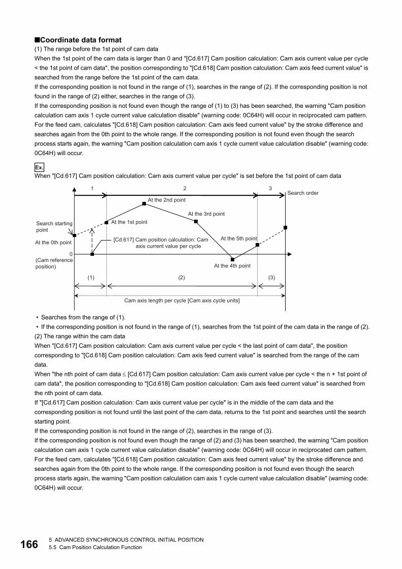
16
■Coordinate data format(1) The range before the 1st point of cam data
When the 1st point of the cam data is larger than 0 and "[Cd.617] Cam position calculation: Cam axis current value per cycle
< the 1st point of cam data", the position corresponding to "[Cd.618] Cam position calculation: Cam axis feed current value" is
searched from the range before the 1st point of the cam data.
If the corresponding position is not found in the range of (1), searches in the range of (2). If the corresponding position is not
found in the range of (2) either, searches in the range of (3).
If the corresponding position is not found even though the range of (1) to (3) has been searched, the warning "Cam position
calculation cam axis 1 cycle current value calculation disable" (warning code: 0C64H) will occur in reciprocated cam pattern.
For the feed cam, calculates "[Cd.618] Cam position calculation: Cam axis feed current value" by the stroke difference and
searches again from the 0th point to the whole range. If the corresponding position is not found even though the search
process starts again, the warning "Cam position calculation cam axis 1 cycle current value calculation disable" (warning code:
0C64H) will occur.
Ex.
When "[Cd.617] Cam position calculation: Cam axis current value per cycle" is set before the 1st point of cam data
• Searches from the range of (1).
• If the corresponding position is not found in the range of (1), searches from the 1st point of the cam data in the range of (2).
(2) The range within the cam data
When "[Cd.617] Cam position calculation: Cam axis current value per cycle < the last point of cam data", the position
corresponding to "[Cd.618] Cam position calculation: Cam axis feed current value" is searched from the range of the cam
data.
When "the nth point of cam data [Cd.617] Cam position calculation: Cam axis current value per cycle < the n + 1st point of
cam data", the position corresponding to "[Cd.618] Cam position calculation: Cam axis feed current value" is searched from
the nth point of cam data.
If "[Cd.617] Cam position calculation: Cam axis current value per cycle" is in the middle of the cam data and the
corresponding position is not found until the last point of the cam data, returns to the 1st point and searches until the search
starting point.
If the corresponding position is not found in the range of (2), searches in the range of (3).
If the corresponding position is not found even though the range of (2) and (3) has been searched, the warning "Cam position
calculation cam axis 1 cycle current value calculation disable" (warning code: 0C64H) will occur in reciprocated cam pattern.
For the feed cam, calculates "[Cd.618] Cam position calculation: Cam axis feed current value" by the stroke difference and
searches again from the 0th point to the whole range. If the corresponding position is not found even though the search
process starts again, the warning "Cam position calculation cam axis 1 cycle current value calculation disable" (warning code:
0C64H) will occur.
0
2 31
(Cam reference position)
Cam axis length per cycle [Cam axis cycle units]
At the 1st point At the 3rd point
At the 4th point
At the 5th point
(1) (2) (3)
Search starting point
At the 0th point
Search order
[Cd.617] Cam position calculation: Cam axis current value per cycle
At the 2nd point
65 ADVANCED SYNCHRONOUS CONTROL INITIAL POSITION5.5 Cam Position Calculation Function
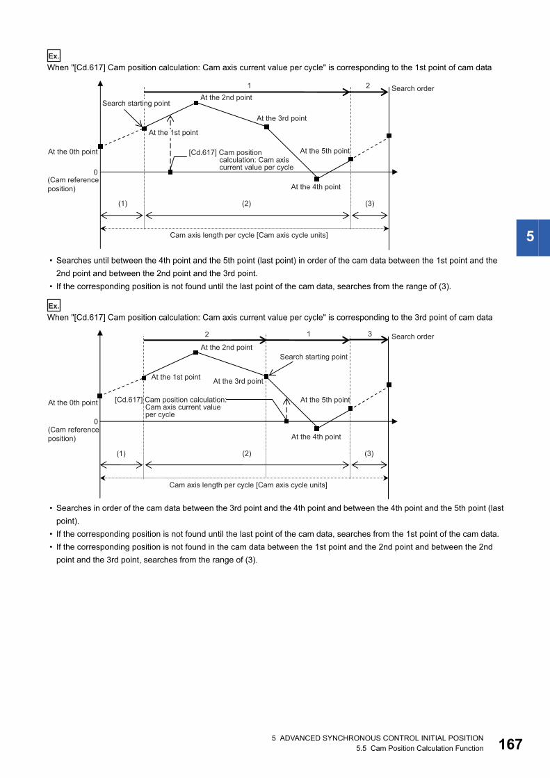
5
Ex.
When "[Cd.617] Cam position calculation: Cam axis current value per cycle" is corresponding to the 1st point of cam data
• Searches until between the 4th point and the 5th point (last point) in order of the cam data between the 1st point and the
2nd point and between the 2nd point and the 3rd point.
• If the corresponding position is not found until the last point of the cam data, searches from the range of (3).
Ex.
When "[Cd.617] Cam position calculation: Cam axis current value per cycle" is corresponding to the 3rd point of cam data
• Searches in order of the cam data between the 3rd point and the 4th point and between the 4th point and the 5th point (last
point).
• If the corresponding position is not found until the last point of the cam data, searches from the 1st point of the cam data.
• If the corresponding position is not found in the cam data between the 1st point and the 2nd point and between the 2nd
point and the 3rd point, searches from the range of (3).
0
1 2
(Cam reference position)
Cam axis length per cycle [Cam axis cycle units]
At the 4th point
(1) (2) (3)
At the 0th point
Search order
At the 3rd point
Search starting point At the 2nd point
At the 5th point [Cd.617] Cam position calculation: Cam axis current value per cycle
At the 1st point
0
12 3
(Cam reference position)
Cam axis length per cycle [Cam axis cycle units]
At the 1st point
At the 4th point
(1) (2) (3)
Search starting point
At the 0th point
Search order
At the 3rd point
At the 2nd point
At the 5th point [Cd.617] Cam position calculation: Cam axis current value per cycle
5 ADVANCED SYNCHRONOUS CONTROL INITIAL POSITION5.5 Cam Position Calculation Function 167
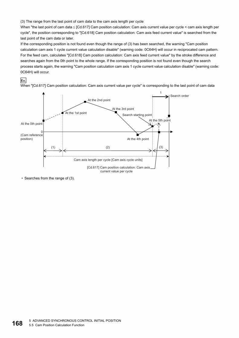
16
(3) The range from the last point of cam data to the cam axis length per cycle
When "the last point of cam data [Cd.617] Cam position calculation: Cam axis current value per cycle < cam axis length per
cycle", the position corresponding to "[Cd.618] Cam position calculation: Cam axis feed current value" is searched from the
last point of the cam data or later.
If the corresponding position is not found even though the range of (3) has been searched, the warning "Cam position
calculation cam axis 1 cycle current value calculation disable" (warning code: 0C64H) will occur in reciprocated cam pattern.
For the feed cam, calculates "[Cd.618] Cam position calculation: Cam axis feed current value" by the stroke difference and
searches again from the 0th point to the whole range. If the corresponding position is not found even though the search
process starts again, the warning "Cam position calculation cam axis 1 cycle current value calculation disable" (warning code:
0C64H) will occur.
Ex.
When "[Cd.617] Cam position calculation: Cam axis current value per cycle" is corresponding to the last point of cam data
• Searches from the range of (3).
0
1
(Cam reference position)
Cam axis length per cycle [Cam axis cycle units]
At the 1st point At the 3rd point
At the 4th point
(1) (2)
Search starting point
At the 0th point
Search order
At the 5th point
(3)
At the 2nd point
[Cd.617] Cam position calculation: Cam axis current value per cycle
85 ADVANCED SYNCHRONOUS CONTROL INITIAL POSITION5.5 Cam Position Calculation Function

5
5.6 Method to Restart Synchronous ControlThe relationship of the synchronous position for synchronous control is always saved in the Simple Motion module.
Synchronous control can be restarted without returning all axes to their starting points by restoring the synchronized
relationship through the synchronous control initial position parameters (Page 147 Synchronous Control Initial Position
Parameters).
The reference axis used to restart synchronous control is different for each system. The following procedure shows an
example of how to restore synchronized values based on the servo input axis as reference position.
ExampleRestoring 2 output axes (axis 2, axis 3) based on the servo input axis (axis 1) as the reference position. (Press conveyance
device)
■Procedure for synchronous control (first time)
1. Execute home position return for axis 1, 2 and 3, and position to the synchronization starting point.
2. Set the synchronous control initial position parameters for axis 2 and 3 as follows.
3. Turn ON the bits for axis 2 and 3 in "[Cd.380] Synchronous control start" to start synchronous control.
■Procedure for restarting synchronous control
1. Set the synchronous control initial position parameters for axis 2 and 3 as follows.
2. Turn ON the bits for axes 2 and 3 in "[Cd.381] Synchronous control analysis mode", and then turn ON the bits for axes 2
and 3 in "[Cd.380] Synchronous control start" to execute the synchronous control analysis. The analyzed result is
updated in [Md.400] to [Md.425].
3. Position axes 2 and 3 to "[Md.409] Cam axis feed current value" which has been updated in 2.
4. Turn OFF the bits for axes 2 and 3 in "[Cd.381] Synchronous control analysis mode", and then turn ON the bits for axes
2 and 3 in "[Cd.380] Synchronous control start" to start synchronous control.
Setting item Setting value
[Pr.460] Setting method of current value per cycle after main shaft gear 2: Calculate from input axis
[Pr.462] Cam axis position restoration object 0: Cam axis current value per cycle restoration
[Pr.463] Setting method of cam reference position 2: Feed current value
[Pr.468] Cam axis current value per cycle (Initial setting) 0
Setting item Setting value
[Pr.460] Setting method of current value per cycle after main shaft gear 2: Calculate from input axis
[Pr.462] Cam axis position restoration object 2: Cam axis feed current value restoration
[Pr.463] Setting method of cam reference position 0: Previous value
[Pr.464] Setting method of cam axis current value per cycle 2: Current value per cycle after main shaft gear
Main shaftgear
Axis 3
Axis 1
Main shaftgear
Axis 2
Axis 1
Pressing position(Axis 1)
X axis of workpiece conveyance (Axis 2)
Y axis of workpiece conveyance (Axis 3)
5 ADVANCED SYNCHRONOUS CONTROL INITIAL POSITION5.6 Method to Restart Synchronous Control 169

17
APPENDICESAppendix 1 List of Buffer Memory Addresses (for
Synchronous Control)The following shows the relation between the buffer memory addresses and the various items.
Refer to the following for the list of general buffer memory addresses.
MELSEC iQ-R Simple Motion Module User's Manual (Application)
Refer to the following for the list of buffer memory addresses for network.
MELSEC iQ-R Simple Motion Module User's Manual (Network)
Parameter
■Servo input axis parametern: Axis No. - 1 (n: Axis No. - 17 for axis 17 to axis 32)
■Synchronous encoder axis parameterj: Synchronous encoder axis No. - 1 (j: Axis No. - 17 for axis 17 to axis 32)
■Synchronous encoder axis parameter via link device [RD77GF]j: Synchronous encoder axis No. - 1 (j: Axis No. - 17 for axis 17 to axis 32)
Item Buffer memory address
Axis 1 to axis 16 Axis 17 to axis 32
[Pr.300] Servo input axis type 32800+10n 1032800+10n
[Pr.301] Servo input axis smoothing time constant 32801+10n 1032801+10n
[Pr.302] Servo input axis phase compensation advance time 32802+10n
32803+10n
1032802+10n
1032803+10n
[Pr.303] Servo input axis phase compensation time constant 32804+10n 1032804+10n
[Pr.304] Servo input axis rotation direction restriction 32805+10n 1032805+10n
Item Buffer memory address
Axis 1 to axis 16 Axis 17 to axis 32
[Pr.320] Synchronous encoder axis type 34720+20j 1034720+20j
[Pr.321] Synchronous encoder axis unit setting 34721+20j 1034721+20j
[Pr.322] Synchronous encoder axis unit conversion: Numerator 34722+20j
34723+20j
1034722+20j
1034723+20j
[Pr.323] Synchronous encoder axis unit conversion: Denominator 34724+20j
34725+20j
1034724+20j
1034725+20j
[Pr.324] Synchronous encoder axis length per cycle 34726+20j
34727+20j
1034726+20j
1034727+20j
[Pr.325] Synchronous encoder axis smoothing time constant 34728+20j 1034728+20j
[Pr.326] Synchronous encoder axis phase compensation advance time 34730+20j
34731+20j
1034730+20j
1034731+20j
[Pr.327] Synchronous encoder axis phase compensation time constant 34732+20j 1034732+20j
[Pr.328] Synchronous encoder axis rotation direction restriction 34733+20j 1034733+20j
[Pr.329] Resolution of synchronous encoder via CPU 34734+20j
34735+20j
1034734+20j
1034735+20j
Item Buffer memory address
Axis 1 to axis 16 Axis 17 to axis 32
[Pr.710] Synchronous encoder axis: Link device type 35520+20j 1035520+20j
[Pr.711] Synchronous encoder axis: Link device start No. 35521+20j 1035521+20j
[Pr.712] Synchronous encoder axis: Link device count direction setting 35526+20j 1035526+20j
[Pr.713] Synchronous encoder axis: Ring counter maximum value 35522+20j
35523+20j
1035522+20j
1035523+20j
0APPENDICESAppendix 1 List of Buffer Memory Addresses (for Synchronous Control)

A
■Synchronous parameter: Main shaftn: Axis No. - 1 (n: Axis No. - 17 for axis 17 to axis 32)
■Synchronous parameter: Auxiliary shaftn: Axis No. - 1 (n: Axis No. - 17 for axis 17 to axis 32)
[Pr.714] Synchronous encoder axis: Ring counter minimum value 35524+20j
35525+20j
1035524+20j
1035525+20j
[Pr.1010] Synchronous encoder axis start request: Link device type 35530+20j 1035530+20j
[Pr.1011] Synchronous encoder axis start request: Link device start No. 35531+20j 1035531+20j
[Pr.1012] Synchronous encoder axis start request: Link device bit specification 35532+20j 1035532+20j
[Pr.1013] Synchronous encoder axis start request: Link device logic setting 35533+20j 1035533+20j
Item Buffer memory address
Axis 1 to axis 16 Axis 17 to axis 32
[Pr.400] Main input axis No. 36400+200n 1036400+200n
[Pr.401] Sub input axis No. 36401+200n 1036401+200n
[Pr.402] Composite main shaft gear 36402+200n 1036402+200n
[Pr.403] Main shaft gear: Numerator 36404+200n
36405+200n
1036404+200n
1036405+200n
[Pr.404] Main shaft gear: Denominator 36406+200n
36407+200n
1036406+200n
1036407+200n
[Pr.405] Main shaft clutch control setting 36408+200n 1036408+200n
[Pr.406] Main shaft clutch reference address setting 36409+200n 1036409+200n
[Pr.407] Main shaft clutch ON address 36410+200n
36411+200n
1036410+200n
1036411+200n
[Pr.408] Movement amount before main shaft clutch ON 36412+200n
36413+200n
1036412+200n
1036413+200n
[Pr.409] Main shaft clutch OFF address 36414+200n
36415+200n
1036414+200n
1036415+200n
[Pr.410] Movement amount before main shaft clutch OFF 36416+200n
36417+200n
1036416+200n
1036417+200n
[Pr.411] Main shaft clutch smoothing method 36418+200n 1036418+200n
[Pr.412] Main shaft clutch smoothing time constant 36419+200n 1036419+200n
[Pr.413] Slippage at main shaft clutch ON 36420+200n
36421+200n
1036420+200n
1036421+200n
[Pr.414] Slippage at main shaft clutch OFF 36422+200n
36423+200n
1036422+200n
1036423+200n
Item Buffer memory address
Axis 1 to axis 16 Axis 17 to axis 32
[Pr.418] Auxiliary shaft axis No. 36430+200n 1036430+200n
[Pr.419] Composite auxiliary shaft gear 36431+200n 1036431+200n
[Pr.420] Auxiliary shaft gear: Numerator 36432+200n
36433+200n
1036432+200n
1036433+200n
[Pr.421] Auxiliary shaft gear: Denominator 36434+200n
36435+200n
1036434+200n
1036435+200n
[Pr.422] Auxiliary shaft clutch control setting 36436+200n 1036436+200n
[Pr.423] Auxiliary shaft clutch reference address setting 36437+200n 1036437+200n
[Pr.424] Auxiliary shaft clutch ON address 36438+200n
36439+200n
1036438+200n
1036439+200n
[Pr.425] Movement amount before auxiliary shaft clutch ON 36440+200n
36441+200n
1036440+200n
1036441+200n
[Pr.426] Auxiliary shaft clutch OFF address 36442+200n
36443+200n
1036442+200n
1036443+200n
[Pr.427] Movement amount before auxiliary shaft clutch OFF 36444+200n
36445+200n
1036444+200n
1036445+200n
[Pr.428] Auxiliary shaft clutch smoothing method 36446+200n 1036446+200n
Item Buffer memory address
Axis 1 to axis 16 Axis 17 to axis 32
APPENDICESAppendix 1 List of Buffer Memory Addresses (for Synchronous Control) 171

17
■Synchronous parameter: Speed change gearn: Axis No. - 1 (n: Axis No. - 17 for axis 17 to axis 32)
■Synchronous parameter: Output axisn: Axis No. - 1 (n: Axis No. - 17 for axis 17 to axis 32)
■Synchronous parameter: Synchronous control initial positionn: Axis No. - 1 (n: Axis No. - 17 for axis 17 to axis 32)
[Pr.429] Auxiliary shaft clutch smoothing time constant 36447+200n 1036447+200n
[Pr.430] Slippage at auxiliary shaft clutch ON 36448+200n
36449+200n
1036448+200n
1036449+200n
[Pr.431] Slippage at auxiliary shaft clutch OFF 36450+200n
36451+200n
1036450+200n
1036451+200n
Item Buffer memory address
Axis 1 to axis 16 Axis 17 to axis 32
[Pr.434] Speed change gear 36460+200n 1036460+200n
[Pr.435] Speed change gear smoothing time constant 36461+200n 1036461+200n
[Pr.436] Speed change ratio: Numerator 36462+200n
36463+200n
1036462+200n
1036463+200n
[Pr.437] Speed change ratio: Denominator 36464+200n
36465+200n
1036464+200n
1036465+200n
Item Buffer memory address
Axis 1 to axis 16 Axis 17 to axis 32
[Pr.438] Cam axis cycle unit setting 36470+200n 1036470+200n
[Pr.439] Cam axis length per cycle 36472+200n
36473+200n
1036472+200n
1036473+200n
[Pr.440] Cam No. 36474+200n 1036474+200n
[Pr.441] Cam stroke amount 36476+200n
36477+200n
1036476+200n
1036477+200n
[Pr.442] Cam axis length per cycle change setting 36471+200n 1036471+200n
[Pr.444] Cam axis phase compensation advance time 36482+200n
36483+200n
1036482+200n
1036483+200n
[Pr.445] Cam axis phase compensation time constant 36484+200n 1036484+200n
[Pr.446] Synchronous control deceleration time 36485+200n 1036485+200n
[Pr.447] Output axis smoothing time constant 36486+200n 1036486+200n
Item Buffer memory address
Axis 1 to axis 16 Axis 17 to axis 32
[Pr.460] Setting method of current value per cycle after main shaft gear 36500+200n 1036500+200n
[Pr.461] Setting method of current value per cycle after auxiliary shaft gear 36501+200n 1036501+200n
[Pr.462] Cam axis position restoration object 36502+200n 1036502+200n
[Pr.463] Setting method of cam reference position 36503+200n 1036503+200n
[Pr.464] Setting method of cam axis current value per cycle 36504+200n 1036504+200n
[Pr.465] Current value per cycle after main shaft gear (Initial setting) 36506+200n
36507+200n
1036506+200n
1036507+200n
[Pr.466] Current value per cycle after auxiliary shaft gear (Initial setting) 36508+200n
36509+200n
1036508+200n
1036509+200n
[Pr.467] Cam reference position (Initial setting) 36510+200n
36511+200n
1036510+200n
1036511+200n
[Pr.468] Cam axis current value per cycle (Initial setting) 36512+200n
36513+200n
1036512+200n
1036513+200n
Item Buffer memory address
Axis 1 to axis 16 Axis 17 to axis 32
2APPENDICESAppendix 1 List of Buffer Memory Addresses (for Synchronous Control)

A
Monitor data
■Servo input axis monitor datan: Axis No. - 1 (n: Axis No. - 17 for axis 17 to axis 32)
■Synchronous encoder axis monitor dataj: Synchronous encoder axis No. - 1 (j: Axis No. - 17 for axis 17 to axis 32)
■Synchronous control monitor datan: Axis No. - 1 (n: Axis No. - 17 for axis 17 to axis 32)
Item Buffer memory address
Axis 1 to axis 16 Axis 17 to axis 32
[Md.300] Servo input axis current value 33120+10n
33121+10n
1033120+10n
1033121+10n
[Md.301] Servo input axis speed 33122+10n
33123+10n
1033122+10n
1033123+10n
[Md.302] Servo input axis phase compensation amount 33124+10n
33125+10n
1033124+10n
1033125+10n
[Md.303] Servo input axis rotation direction restriction amount 33126+10n
33127+10n
1033126+10n
1033127+10n
Item Buffer memory address
Axis 1 to axis 16 Axis 17 to axis 32
[Md.320] Synchronous encoder axis current value 35200+20j
35201+20j
1035200+20j
1035201+20j
[Md.321] Synchronous encoder axis current value per cycle 35202+20j
35203+20j
1035202+20j
1035203+20j
[Md.322] Synchronous encoder axis speed 35204+20j
35205+20j
1035204+20j
1035205+20j
[Md.323] Synchronous encoder axis phase compensation amount 35206+20j
35207+20j
1035206+20j
1035207+20j
[Md.324] Synchronous encoder axis rotation direction restriction amount 35208+20j
35209+20j
1035208+20j
1035209+20j
[Md.325] Synchronous encoder axis status 35210+20j 1035210+20j
[Md.326] Synchronous encoder axis error No. 35211+20j 1035211+20j
[Md.327] Synchronous encoder axis warning No. 35212+20j 1035212+20j
Item Buffer memory address
Axis 1 to axis 16 Axis 17 to axis 32
[Md.400] Current value after composite main shaft gear 42800+40n
42801+40n
1042800+40n
1042801+40n
[Md.401] Current value per cycle after main shaft gear 42802+40n
42803+40n
1042802+40n
1042803+40n
[Md.402] Current value per cycle after auxiliary shaft gear 42804+40n
42805+40n
1042804+40n
1042805+40n
[Md.406] Cam axis phase compensation amount 42810+40n
42811+40n
1042810+40n
1042811+40n
[Md.407] Cam axis current value per cycle 42812+40n
42813+40n
1042812+40n
1042813+40n
[Md.408] Cam reference position 42814+40n
42815+40n
1042814+40n
1042815+40n
[Md.409] Cam axis feed current value 42816+40n
42817+40n
1042816+40n
1042817+40n
[Md.410] Execute cam No. 42818+40n 1042818+40n
[Md.411] Execute cam stroke amount 42820+40n
42821+40n
1042820+40n
1042821+40n
[Md.412] Execute cam axis length per cycle 42822+40n
42823+40n
1042822+40n
1042823+40n
[Md.420] Main shaft clutch ON/OFF status 42828+40n 1042828+40n
[Md.421] Main shaft clutch smoothing status 42829+40n 1042829+40n
APPENDICESAppendix 1 List of Buffer Memory Addresses (for Synchronous Control) 173

17
■Synchronous control monitor data: Cam position calculation
[Md.422] Main shaft clutch slippage (accumulative) 42830+40n
42831+40n
1042830+40n
1042831+40n
[Md.423] Auxiliary shaft clutch ON/OFF status 42832+40n 1042832+40n
[Md.424] Auxiliary shaft clutch smoothing status 42833+40n 1042833+40n
[Md.425] Auxiliary shaft clutch slippage (accumulative) 42834+40n
42835+40n
1042834+40n
1042835+40n
Item Buffer memory address
[Md.600] Cam position calculation result 53800
53801
Item Buffer memory address
Axis 1 to axis 16 Axis 17 to axis 32
4APPENDICESAppendix 1 List of Buffer Memory Addresses (for Synchronous Control)

A
Control data
■Synchronous control system control data
■Synchronous encoder axis control dataj: Synchronous encoder axis No. - 1 (j: Axis No. - 17 for axis 17 to axis 32)
■Control data for synchronous controln: Axis No. - 1 (n: Axis No. - 17 for axis 17 to axis 32)
■Cam operation control data: Cam data operation
Item Buffer memory address
Axis 1 to axis 16 Axis 17 to axis 32
[Cd.380] Synchronous control start 36320 1036320
[Cd.381] Synchronous control analysis mode 36322 1036322
Item Buffer memory address
Axis 1 to axis 16 Axis 17 to axis 32
[Cd.320] Synchronous encoder axis control start 35040+10j 1035040+10j
[Cd.321] Synchronous encoder axis control method 35041+10j 1035041+10j
[Cd.322] Synchronous encoder axis current value setting address 35042+10j
35043+10j
1035042+10j
1035043+10j
[Cd.323] Synchronous encoder axis error reset 35044+10j 1035044+10j
[Cd.324] Connection command of synchronous encoder via CPU 35045+10j 1035045+10j
[Cd.325] Input value for synchronous encoder via CPU 35046+10j
35047+10j
1035046+10j
1035047+10j
Item Buffer memory address
Axis 1 to axis 16 Axis 17 to axis 32
[Cd.400] Main shaft clutch command 44080+20n 1044080+20n
[Cd.401] Main shaft clutch control invalid command 44081+20n 1044081+20n
[Cd.402] Main shaft clutch forced OFF command 44082+20n 1044082+20n
[Cd.403] Auxiliary shaft clutch command 44083+20n 1044083+20n
[Cd.404] Auxiliary shaft clutch control invalid command 44084+20n 1044084+20n
[Cd.405] Auxiliary shaft clutch forced OFF command 44085+20n 1044085+20n
[Cd.406] Synchronous control change request 44086+20n 1044086+20n
[Cd.407] Synchronous control change command 44087+20n 1044087+20n
[Cd.408] Synchronous control change value 44088+20n
44089+20n
1044088+20n
1044089+20n
[Cd.409] Synchronous control reflection time 44090+20n 1044090+20n
Item Buffer memory address
[Cd.600] Cam data operation request 45000 [RD77MS]
600000 [RD77GF]
[Cd.601] Operation cam No. 45001 [RD77MS]
600001 [RD77GF]
[Cd.602] Cam data first position 45002 [RD77MS]
600002 [RD77GF]
[Cd.603] Number of cam data operation points 45003 [RD77MS]
600003 [RD77GF]
[Cd.604] Cam data format 45004 [RD77MS]
600004 [RD77GF]
[Cd.605] Cam resolution/coordinate number 45005 [RD77MS]
600005 [RD77GF]
[Cd.606] Cam data starting point 45006 [RD77MS]
600006 [RD77GF]
[Cd.607] Cam data value *1 45008 to 53199 [RD77MS]
600008 to 862147 [RD77GF]
APPENDICESAppendix 1 List of Buffer Memory Addresses (for Synchronous Control) 175

17
*1 The item details on the cam data are shown below.
• Data for rotary cutter (central reference) [RD77GF]
• Easy stroke ratio cam data [RD77GF]
Details Buffer memory address
Resolution 600008
600009
Auto-generation option 600010
Synchronous section acceleration ratio 600011
Sheet length 600012
600013
Sheet synchronous width 600014
600015
Synchronous axis length 600016
600017
Synchronous position adjustment 600018
600019
Acceleration/deceleration width 600020
600021
Number of cutter 600022
Asynchronous speed result 600023
Details Buffer memory address
Resolution 600008
600009
Cam axis length per cycle 600010
600011
Cam data starting point 600012
600013
Number of sections 600014
Section 1 Cam curve type 600016
End point 600018
600019
Stroke 600020
600021
Section 32 Cam curve type 600202
End point 600204
600205
Stroke 600206
600207
6APPENDICESAppendix 1 List of Buffer Memory Addresses (for Synchronous Control)

A
• Advanced stroke ratio cam data for auto-generation [RD77GF]
Details Buffer memory address
Resolution 600008
600009
Cam axis length per cycle 600010
600011
Cam stroke amount 600012
600013
Unit setting 600014
Cam data starting point 600016
600017
Number of sections 600018
Section 1 Cam curve type 600020
End point 600022
600023
Stroke 600024
600025
Curve applicable range (P1) 600026
Curve applicable range (P2) 600027
Acceleration/deceleration range compensation (Range L1) 600028
Acceleration/deceleration range compensation (Range L2) 600029
Section 360 Cam curve type 603610
End point 603612
603613
Stroke 603614
603615
Curve applicable range (P1) 603616
Curve applicable range (P2) 603617
Acceleration/deceleration range compensation (Range L1) 603618
Acceleration/deceleration range compensation (Range L2) 603619
APPENDICESAppendix 1 List of Buffer Memory Addresses (for Synchronous Control) 177

17
■Cam operation control data: Cam auto-generation
*1 The item details on the auto-generation parameter are shown below.
• Cam auto-generation data for rotary cutter [RD77MS]
• Cam auto-generation data for rotary cutter (central reference) [RD77GF]
Item Buffer memory address
[Cd.608] Cam auto-generation request 53200 [RD77MS]
862200 [RD77GF]
[Cd.609] Cam auto-generation cam No. 53201 [RD77MS]
862201 [RD77GF]
[Cd.610] Cam auto-generation type 53202 [RD77MS]
862202 [RD77GF]
[Cd.611] Cam auto-generation data*1 53204 to 53779 [RD77MS]
862204 to 866295 [RD77GF]
Details Buffer memory address
Resolution 53204
Sheet length 53206
53207
Sheet synchronous width 53208
53209
Synchronous axis length 53210
53211
Synchronization starting point 53212
53213
Synchronous section acceleration ratio 53214
Details Buffer memory address
Resolution 862204
862205
Auto-generation option 862206
Synchronous section acceleration ratio 862207
Sheet length 862208
862209
Sheet synchronous width 862210
862211
Synchronous axis length 862212
862213
Synchronous position adjustment 862214
862215
Acceleration/deceleration width 862216
862217
Number of cutter 862218
Asynchronous speed result 862219
8APPENDICESAppendix 1 List of Buffer Memory Addresses (for Synchronous Control)

A
• Easy stroke ratio cam data for auto-generation [RD77GF]
• Advanced stroke ratio cam data for auto-generation [RD77GF]
Details Buffer memory address
Resolution 862204
862205
Cam axis length per cycle 862206
862207
Cam data starting point 862208
862209
Number of sections 862210
Section 1 Cam curve type 862212
End point 862214
862215
Stroke 862216
862217
Section 32 Cam curve type 862398
End point 862400
862401
Stroke 862402
862403
Details Buffer memory address
Resolution 862204
862205
Cam axis length per cycle 862206
862207
Cam stroke amount 862208
862209
Unit setting 862210
Cam data starting point 862212
862213
Number of sections 862214
Section 1 Cam curve type 862216
End point 862218
862219
Stroke 862220
862221
Curve applicable range (P1) 862222
Curve applicable range (P2) 862223
Acceleration/deceleration range compensation (Range L1) 862224
Acceleration/deceleration range compensation (Range L2) 862225
Section 360 Cam curve type 865806
End point 865808
865809
Stroke 865810
865811
Curve applicable range (P1) 865812
Curve applicable range (P2) 865813
Acceleration/deceleration range compensation (Range L1) 865814
Acceleration/deceleration range compensation (Range L2) 865815
APPENDICESAppendix 1 List of Buffer Memory Addresses (for Synchronous Control) 179
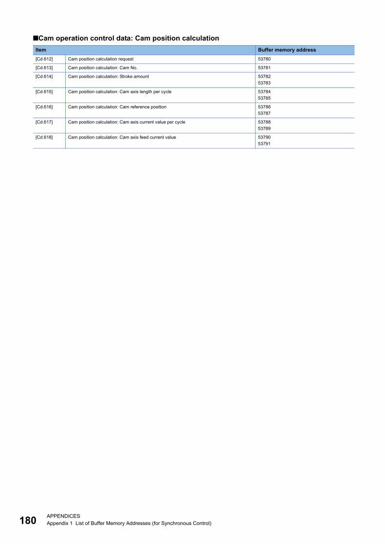
18
■Cam operation control data: Cam position calculation
Item Buffer memory address
[Cd.612] Cam position calculation request 53780
[Cd.613] Cam position calculation: Cam No. 53781
[Cd.614] Cam position calculation: Stroke amount 53782
53783
[Cd.615] Cam position calculation: Cam axis length per cycle 53784
53785
[Cd.616] Cam position calculation: Cam reference position 53786
53787
[Cd.617] Cam position calculation: Cam axis current value per cycle 53788
53789
[Cd.618] Cam position calculation: Cam axis feed current value 53790
53791
0APPENDICESAppendix 1 List of Buffer Memory Addresses (for Synchronous Control)

A
Appendix 2 Sample Program of Synchronous Control of the RD77MS
The following shows a sample program of executing synchronous control on the axis 1 with the axis 4 as an input axis using
4-axis modules. (The axis 4 is configured as the virtual servo amplifier.)
1. Set MR-J4(W)-B(-RJ) on the axis 1 and the virtual servo amplifier on the axis 4 in the "System Configuration" window.
2. Set the axis 4 as the servo input axis in the "Input Axis Parameter" window.
APPENDICESAppendix 2 Sample Program of Synchronous Control of the RD77MS 181
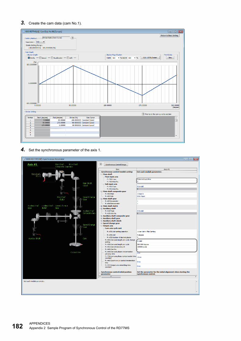
18
3. Create the cam data (cam No.1).
4. Set the synchronous parameter of the axis 1.
2APPENDICESAppendix 2 Sample Program of Synchronous Control of the RD77MS
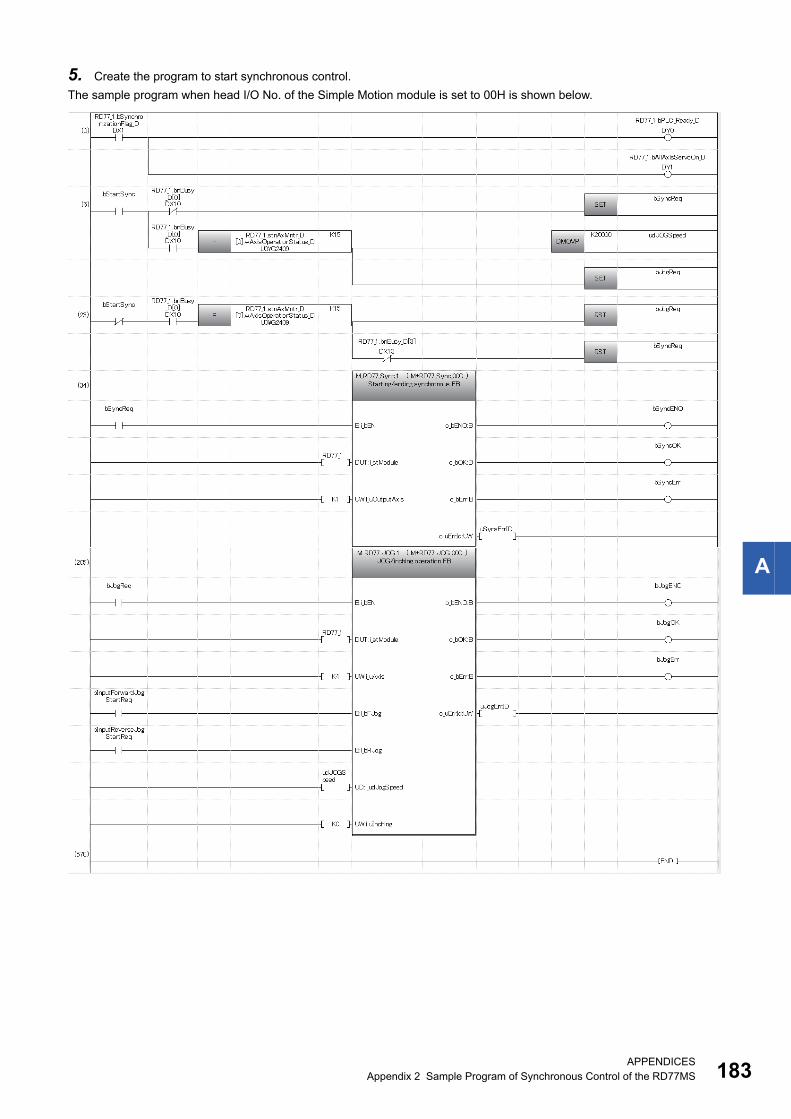
A
5. Create the program to start synchronous control.
The sample program when head I/O No. of the Simple Motion module is set to 00H is shown below.
APPENDICESAppendix 2 Sample Program of Synchronous Control of the RD77MS 183

18
Classification Label name Description
Module label RD77_1.bSynchronizationFlag_D Synchronization flag
RD77_1.bPLC_Ready_D PLC READY
RD77_1.bAllAxisServoOn_D All axis servo ON
RD77_1.bnBusy_D[0] Axis 1 BUSY
RD77_1.stnAxMntr_D[0].wAxisOperationStatus_D Axis 1 Axis operation status
RD77_1.bnBusy_D[3] Axis 4 BUSY
Global label, Local label Defines the global label or the local label as follows. The settings of Assign (Device/Label) are not required for the label that the
assignment device is not set because the unused internal relay and data device are automatically assigned.
4APPENDICESAppendix 2 Sample Program of Synchronous Control of the RD77MS

A
MEMO
APPENDICESAppendix 2 Sample Program of Synchronous Control of the RD77MS 185

18
INDEX
A
Auxiliary shaft axis No. . . . . . . . . . . . . . . . 101,102Auxiliary shaft clutch command . . . . . . . . . . . . 109Auxiliary shaft clutch control invalid command . . 109Auxiliary shaft clutch control setting. . . . . . . 103,104Auxiliary shaft clutch forced OFF command . . . . 109Auxiliary shaft clutch OFF address . . . . . . . 104,107Auxiliary shaft clutch ON address . . . . . . . . 103,107Auxiliary shaft clutch ON/OFF status . . . . . . 136,139Auxiliary shaft clutch reference address setting. . . . . . . . . . . . . . . . . . . . . . . . . . . . . . . . 103,106Auxiliary shaft clutch slippage (accumulative). . . . . . . . . . . . . . . . . . . . . . . . . . . . . . . . 136,139Auxiliary shaft clutch smoothing method . . . . . . 108Auxiliary shaft clutch smoothing status . . . . 136,139Auxiliary shaft clutch smoothing time constant. . . . . . . . . . . . . . . . . . . . . . . . . . . . . . . . 104,108Auxiliary shaft gear
Denominator . . . . . . . . . . . . . . . . . . . . . 101,102Numerator. . . . . . . . . . . . . . . . . . . . . . . 101,102
C
Cam auto-generation cam No. . . . . . . . . . . . . 79,80Cam auto-generation data . . . . . . . . . . . . . . . 79,81Cam auto-generation request . . . . . . . . . . . . . 79,80Cam auto-generation type . . . . . . . . . . . . . . . 79,80Cam axis current value per cycle . . . . . . . . 135,138Cam axis cycle unit setting. . . . . . . . . . . . . 127,128Cam axis feed current value. . . . . . . . . . . . 135,138Cam axis length per cycle . . . . . . . . . . . . . 127,128Cam axis length per cycle change setting . . 127,129Cam axis phase compensation advance time. . . 127Cam axis phase compensation amount . . . . 135,138Cam axis phase compensation time constant. . . . . . . . . . . . . . . . . . . . . . . . . . . . . . . . 127,130Cam axis position restoration object . . . . . . 147,148Cam data first position . . . . . . . . . . . . . . . . . . 74,75Cam data format . . . . . . . . . . . . . . . . . . . . . . 74,76Cam data operation request . . . . . . . . . . . . . . 74,75Cam data starting point . . . . . . . . . . . . . . . . . 74,76Cam data value . . . . . . . . . . . . . . . . . . . . . . 75,77Cam No. . . . . . . . . . . . . . . . . . . . . . . . . . 127,129Cam position calculation
Cam axis current value per cycle . . . . . . . 162,163Cam axis feed current value . . . . . . . . . . 162,163Cam axis length per cycle . . . . . . . . . . . . 162,163Cam No. . . . . . . . . . . . . . . . . . . . . . . . . . . . 162Cam reference position. . . . . . . . . . . . . . 162,163Stroke amount . . . . . . . . . . . . . . . . . . . . 162,163
Cam position calculation request . . . . . . . . 162,163Cam position calculation result . . . . . . . . . . . . . 164Cam reference position . . . . . . . . . . . . . . . 135,138Cam reference position (Initial setting). . . . . 147,149Cam resolution/coordinate number . . . . . . . . . 74,76Cam stroke amount . . . . . . . . . . . . . . . . . . 127,129Composite auxiliary shaft gear . . . . . . . . . . 101,102Composite main shaft gear . . . . . . . . . . . . . . 92,93Connection command of synchronous encoder via CPU. . . . . . . . . . . . . . . . . . . . . . . . . . . . . . . . . . 55,58
Current value after composite main shaft gear. . . . . . . . . . . . . . . . . . . . . . . . . . . . . . . . 135,137Current value per cycle after auxiliary shaft gear. . . . . . . . . . . . . . . . . . . . . . . . . . . . . . . . 135,138Current value per cycle after auxiliary shaft gear (Initialsetting) . . . . . . . . . . . . . . . . . . . . . . . . . . 147,149Current value per cycle after main shaft gear. . . . . . . . . . . . . . . . . . . . . . . . . . . . . . . . 135,138Current value per cycle after main shaft gear (Initialsetting) . . . . . . . . . . . . . . . . . . . . . . . . . . 147,149
E
Execute cam axis length per cycle . . . . . . . 136,138Execute cam No. . . . . . . . . . . . . . . . . . . . 136,138Execute cam stroke amount. . . . . . . . . . . . 136,138
I
Initial setting value of current value per cycle after mainshaft gear . . . . . . . . . . . . . . . . . . . . . . . . 147,149Input value for synchronous encoder via CPU. . . . . . . . . . . . . . . . . . . . . . . . . . . . . . . . . . 55,58
M
Main input axis No. . . . . . . . . . . . . . . . . . . . . . . .92Main shaft clutch command . . . . . . . . . . . . . . . .100Main shaft clutch control invalid command. . . . . .100Main shaft clutch control setting . . . . . . . . . . . 94,96Main shaft clutch forced OFF command . . . . . . .100Main shaft clutch OFF address. . . . . . . . . . . . 95,98Main shaft clutch ON address . . . . . . . . . . . . 94,98Main shaft clutch ON/OFF status . . . . . . . . 136,138Main shaft clutch reference address setting . . . 94,97Main shaft clutch slippage (accumulative) . . 136,139Main shaft clutch smoothing method. . . . . . . . 95,99Main shaft clutch smoothing status . . . . . . . 136,139Main shaft clutch smoothing time constant . . . 95,99Main shaft gear
Denominator . . . . . . . . . . . . . . . . . . . . . . . . . .93Numerator . . . . . . . . . . . . . . . . . . . . . . . . . . .93
Movement amount before auxiliary shaft clutch OFF. . . . . . . . . . . . . . . . . . . . . . . . . . . . . . . . 104,108Movement amount before auxiliary shaft clutch ON. . . . . . . . . . . . . . . . . . . . . . . . . . . . . . . . 103,107Movement amount before main shaft clutch OFF. . . . . . . . . . . . . . . . . . . . . . . . . . . . . . . . . . 95,99Movement amount before main shaft clutch ON. . . . . . . . . . . . . . . . . . . . . . . . . . . . . . . . . . 94,98
N
Number of cam data operation points . . . . . . . 74,76
O
Operation cam No. . . . . . . . . . . . . . . . . . . . . 74,75Output axis smoothing time constant . . . . . 127,130
6

I
R
Resolution of synchronous encoder via CPU . . 47,51
S
Servo input axis current value . . . . . . . . . . . . . . 33Servo input axis phase compensation advance time. . . . . . . . . . . . . . . . . . . . . . . . . . . . . . . . . . 30,31Servo input axis phase compensation amount . . . 34Servo input axis phase compensation time constant. . . . . . . . . . . . . . . . . . . . . . . . . . . . . . . . . . 30,31Servo input axis rotation direction restriction . . 30,32Servo input axis rotation direction restriction amount. . . . . . . . . . . . . . . . . . . . . . . . . . . . . . . . . . . . 34Servo input axis smoothing time constant . . . . 30,31Servo input axis speed . . . . . . . . . . . . . . . . . . . 34Servo input axis type . . . . . . . . . . . . . . . . . . . . . 30Setting method of cam axis current value per cycle. . . . . . . . . . . . . . . . . . . . . . . . . . . . . . . . 147,148Setting method of cam reference position . . 147,148Setting method of current value per cycle after auxiliaryshaft gear. . . . . . . . . . . . . . . . . . . . . . . . . 147,148Setting method of current value per cycle after main shaftgear. . . . . . . . . . . . . . . . . . . . . . . . . . . . . . . . 148Slippage amount at auxiliary shaft clutch OFF . . 104Slippage amount at auxiliary shaft clutch ON. . . . . . . . . . . . . . . . . . . . . . . . . . . . . . . . 104,108Slippage amount at main shaft clutch OFF. . . . 95,99Slippage amount at main shaft clutch ON . . . . 95,99Speed change gear . . . . . . . . . . . . . . . . . . . . . 124Speed change gear smoothing time constant . . . 124Speed change ratio
Denominator . . . . . . . . . . . . . . . . . . . . . . . . 124Numerator. . . . . . . . . . . . . . . . . . . . . . . . . . 124
Sub input axis No. . . . . . . . . . . . . . . . . . . . . . . . 92Synchronous control change command . . . . 131,132Synchronous control change request . . . . . . . . 131Synchronous control change value . . . . . . . 131,133Synchronous control deceleration time . . . . 127,130Synchronous control reflection time. . . . . . . 131,134Synchronous encoder axis
Link device count direction setting . . . . . . . . 52,53Link device start number. . . . . . . . . . . . . . . 52,53Link device type. . . . . . . . . . . . . . . . . . . . . 52,53Ring counter maximum value . . . . . . . . . . . 52,53Ring counter minimum value . . . . . . . . . . . . 52,53
Synchronous encoder axis control method. . . . 55,57Synchronous encoder axis control start . . . . . . 55,56Synchronous encoder axis current value . . . . . . . 59Synchronous encoder axis current value per cycle. . . . . . . . . . . . . . . . . . . . . . . . . . . . . . . . . . . . 59Synchronous encoder axis current value setting address. . . . . . . . . . . . . . . . . . . . . . . . . . . . . . . . . . 55,57Synchronous encoder axis error No . . . . . . . . 59,61Synchronous encoder axis error reset . . . . . . . 55,57Synchronous encoder axis length per cycle . . . 46,49Synchronous encoder axis phase compensationadvance time . . . . . . . . . . . . . . . . . . . . . . . . 46,50Synchronous encoder axis phase compensation amount. . . . . . . . . . . . . . . . . . . . . . . . . . . . . . . . . . 59,60Synchronous encoder axis phase compensation timeconstant . . . . . . . . . . . . . . . . . . . . . . . . . . . . 46,50Synchronous encoder axis rotation direction restrictionamount . . . . . . . . . . . . . . . . . . . . . . . . . 51,59,60
Synchronous encoder axis smoothing time constant. . . . . . . . . . . . . . . . . . . . . . . . . . . . . . . . . . 46,50Synchronous encoder axis speed. . . . . . . . . . 59,60Synchronous encoder axis start request
Link device bit specification . . . . . . . . . . . . 52,54Link device logic setting . . . . . . . . . . . . . . . 52,54Link device start number . . . . . . . . . . . . . . 52,54Link device type . . . . . . . . . . . . . . . . . . . . 52,54
Synchronous encoder axis status . . . . . . . . . . 59,60Synchronous encoder axis type . . . . . . . . . . . 46,47Synchronous encoder axis unit conversion
Denominator . . . . . . . . . . . . . . . . . . . . . . . 46,48Numerator . . . . . . . . . . . . . . . . . . . . . . . . 46,47
Synchronous encoder axis unit setting . . . . . . 46,47Synchronous encoder axis warning No. . . . . . 59,61
187
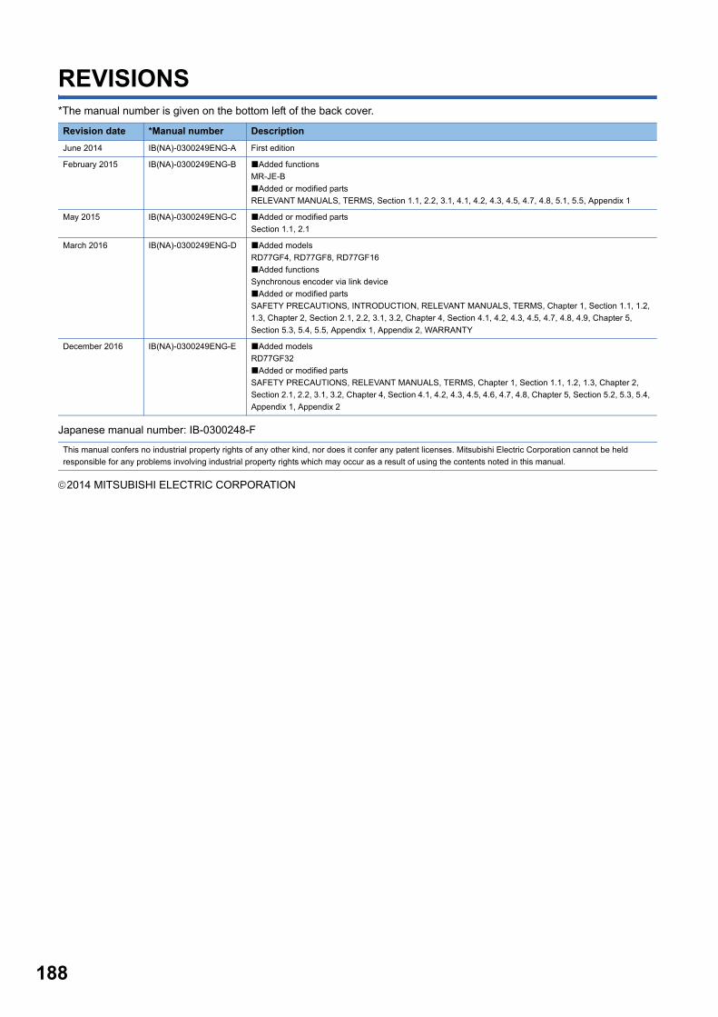
188
REVISIONS*The manual number is given on the bottom left of the back cover.
Japanese manual number: IB-0300248-F
2014 MITSUBISHI ELECTRIC CORPORATION
Revision date *Manual number Description
June 2014 IB(NA)-0300249ENG-A First edition
February 2015 IB(NA)-0300249ENG-B Added functions
MR-JE-B
Added or modified parts
RELEVANT MANUALS, TERMS, Section 1.1, 2.2, 3.1, 4.1, 4.2, 4.3, 4.5, 4.7, 4.8, 5.1, 5.5, Appendix 1
May 2015 IB(NA)-0300249ENG-C Added or modified parts
Section 1.1, 2.1
March 2016 IB(NA)-0300249ENG-D Added models
RD77GF4, RD77GF8, RD77GF16
Added functions
Synchronous encoder via link device
Added or modified parts
SAFETY PRECAUTIONS, INTRODUCTION, RELEVANT MANUALS, TERMS, Chapter 1, Section 1.1, 1.2,
1.3, Chapter 2, Section 2.1, 2.2, 3.1, 3.2, Chapter 4, Section 4.1, 4.2, 4.3, 4.5, 4.7, 4.8, 4.9, Chapter 5,
Section 5.3, 5.4, 5.5, Appendix 1, Appendix 2, WARRANTY
December 2016 IB(NA)-0300249ENG-E Added models
RD77GF32
Added or modified parts
SAFETY PRECAUTIONS, RELEVANT MANUALS, TERMS, Chapter 1, Section 1.1, 1.2, 1.3, Chapter 2,
Section 2.1, 2.2, 3.1, 3.2, Chapter 4, Section 4.1, 4.2, 4.3, 4.5, 4.6, 4.7, 4.8, Chapter 5, Section 5.2, 5.3, 5.4,
Appendix 1, Appendix 2
This manual confers no industrial property rights of any other kind, nor does it confer any patent licenses. Mitsubishi Electric Corporation cannot be held
responsible for any problems involving industrial property rights which may occur as a result of using the contents noted in this manual.
189
WARRANTY
Please confirm the following product warranty details before using this product.
1. Gratis Warranty Term and Gratis Warranty RangeIf any faults or defects (hereinafter "Failure") found to be the responsibility of Mitsubishi occurs during use of the product within the gratis warranty term, the product shall be repaired at no cost via the sales representative or Mitsubishi Service Company.However, if repairs are required onsite at domestic or overseas location, expenses to send an engineer will be solely at the customer's discretion. Mitsubishi shall not be held responsible for any re-commissioning, maintenance, or testing on-site that involves replacement of the failed module.[Gratis Warranty Term]The gratis warranty term of the product shall be for one year after the date of purchase or delivery to a designated place.Note that after manufacture and shipment from Mitsubishi, the maximum distribution period shall be six (6) months, and the longest gratis warranty term after manufacturing shall be eighteen (18) months. The gratis warranty term of repair parts shall not exceed the gratis warranty term before repairs.[Gratis Warranty Range](1) The range shall be limited to normal use within the usage state, usage methods and usage environment, etc., which
follow the conditions and precautions, etc., given in the instruction manual, user's manual and caution labels on the product.
(2) Even within the gratis warranty term, repairs shall be charged for in the following cases.1. Failure occurring from inappropriate storage or handling, carelessness or negligence by the user. Failure caused
by the user's hardware or software design.2. Failure caused by unapproved modifications, etc., to the product by the user.3. When the Mitsubishi product is assembled into a user's device, Failure that could have been avoided if functions
or structures, judged as necessary in the legal safety measures the user's device is subject to or as necessary by industry standards, had been provided.
4. Failure that could have been avoided if consumable parts (battery, backlight, fuse, etc.) designated in the instruction manual had been correctly serviced or replaced.
5. Failure caused by external irresistible forces such as fires or abnormal voltages, and Failure caused by force majeure such as earthquakes, lightning, wind and water damage.
6. Failure caused by reasons unpredictable by scientific technology standards at time of shipment from Mitsubishi.7. Any other failure found not to be the responsibility of Mitsubishi or that admitted not to be so by the user.
2. Onerous repair term after discontinuation of production(1) Mitsubishi shall accept onerous product repairs for seven (7) years after production of the product is discontinued.
Discontinuation of production shall be notified with Mitsubishi Technical Bulletins, etc.(2) Product supply (including repair parts) is not available after production is discontinued.
3. Overseas serviceOverseas, repairs shall be accepted by Mitsubishi's local overseas FA Center. Note that the repair conditions at each FA Center may differ.
4. Exclusion of loss in opportunity and secondary loss from warranty liabilityRegardless of the gratis warranty term, Mitsubishi shall not be liable for compensation to:(1) Damages caused by any cause found not to be the responsibility of Mitsubishi.(2) Loss in opportunity, lost profits incurred to the user by Failures of Mitsubishi products.(3) Special damages and secondary damages whether foreseeable or not, compensation for accidents, and
compensation for damages to products other than Mitsubishi products.(4) Replacement by the user, maintenance of on-site equipment, start-up test run and other tasks.
5. Changes in product specificationsThe specifications given in the catalogs, manuals or technical documents are subject to change without prior notice.

190
TRADEMARKSEthernet is a registered trademark of Fuji Xerox Co., Ltd. in Japan.
Microsoft and Windows are either registered trademarks or trademarks of Microsoft Corporation in the United States and/or
other countries.
The company names, system names and product names mentioned in this manual are either registered trademarks or
trademarks of their respective companies.
In some cases, trademark symbols such as '' or '' are not specified in this manual.


IB(NA)-0300249ENG-E(1612)MEE
MODEL: RD77-U-ADV-E
MODEL CODE: 1XB016
Specifications subject to change without notice.
When exported from Japan, this manual does not require application to theMinistry of Economy, Trade and Industry for service transaction permission.
HEAD OFFICE : TOKYO BUILDING, 2-7-3 MARUNOUCHI, CHIYODA-KU, TOKYO 100-8310, JAPANNAGOYA WORKS : 1-14 , YADA-MINAMI 5-CHOME , HIGASHI-KU, NAGOYA , JAPAN