
Megger, Guide to Portable Appliance Testing
28
WWW.MEGGER.COM Guide to Portable Appliance Testing The word “Megger” is a registered trademark
Transcript of Megger, Guide to Portable Appliance Testing
WW
W.M
EG
GER
.CO
M
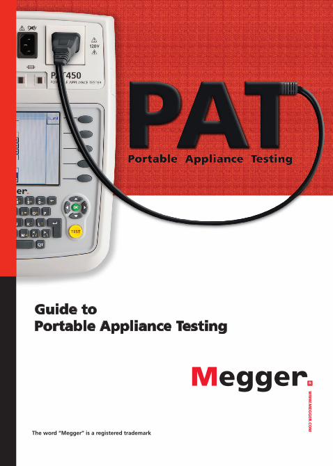
Guide to Portable Appliance Testing
The word “Megger” is a registered trademark
www.megger.com A Guide to PAT Testing 1
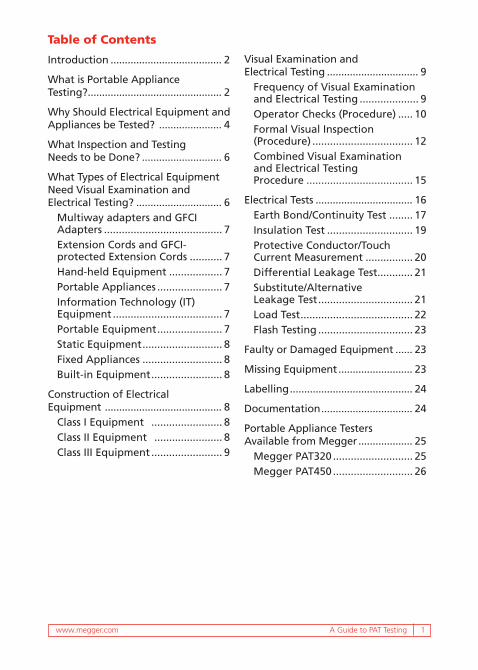
Table of Contents
Introduction ....................................... 2
What is Portable Appliance Testing? ............................................... 2
Why Should Electrical Equipment and Appliances be Tested? ...................... 4
What Inspection and Testing Needs to be Done? ............................ 6
What Types of Electrical Equipment Need Visual Examination and Electrical Testing? .............................. 6
Multiway adapters and GFCI Adapters ........................................ 7Extension Cords and GFCI-protected Extension Cords ........... 7Hand-held Equipment .................. 7Portable Appliances ...................... 7Information Technology (IT) Equipment ..................................... 7Portable Equipment ...................... 7Static Equipment ........................... 8Fixed Appliances ........................... 8Built-in Equipment ........................ 8
Construction of Electrical Equipment ......................................... 8
Class I Equipment ........................ 8Class II Equipment ....................... 8Class III Equipment ........................ 9
Visual Examination and Electrical Testing ................................ 9
Frequency of Visual Examination and Electrical Testing .................... 9Operator Checks (Procedure) ..... 10Formal Visual Inspection (Procedure) .................................. 12Combined Visual Examination and Electrical Testing Procedure .................................... 15
Electrical Tests .................................. 16Earth Bond/Continuity Test ........ 17Insulation Test ............................. 19Protective Conductor/Touch Current Measurement ................ 20Differential Leakage Test............ 21Substitute/Alternative Leakage Test ................................ 21Load Test ...................................... 22Flash Testing ................................ 23
Faulty or Damaged Equipment ...... 23
Missing Equipment .......................... 23
Labelling ........................................... 24
Documentation ................................ 24
Portable Appliance Testers Available from Megger ................... 25
Megger PAT320 ........................... 25Megger PAT450 ........................... 26
2 A Guide to PAT Testing
IntroductionWe live and operate in a world filled with electrical equipment and appliances. Electrical “things” fill our homes, our offices, our manufacturing facilities and the places we go for leisure activity. Electricity poses dangers. Personnel can be injured, sometimes fatally, by malfunctioning electrical equipment. Fires caused by defective electrical equipment and appliances damage property and cause large financial losses for companies. In addition, ours is a litigious society and lawyers are waiting for opportunities to file lawsuits.
How does an equipment rental company ensure that a piece of electrical equipment is electrically sound/safe every time it goes out to a customer? How do in-house tool cribs ensure that their electrical equipment is safe for the next person to use it? How do manufacturing companies ensure that the appliances and equipment they make have no dangerous electrical faults?
Beyond the challenges of protecting personnel and property, many of our manufacturing plants produce electrical equipment for sale into the European Union that must meet European standards. While it is the responsibility of the European importer to ensure that imported items are safe to European standards, any testing done at the destination can prove quite costly for the manufacturer when faults are found. Identifying problems at the manufacturing plant allows for faults to be fixed prior to shipping and export.
A number of European countries, including the UK, make extensive use of portable appliance testing to ensure the safety of electrical equipment and appliances. This booklet will provide a guide to understanding portable appliance testing and how/where it fits as part of an overall electrical safety program. While we use the term “portable appliance testing”, a better description might be portable electrical equipment testing.
What is Portable Appliance Testing?Portable appliance testing is the visual examination and electrical testing of portable electrical equipment used in industrial, commercial or public access areas and locations (including rented property) to ensure they are safe to use, and cannot present an electrical hazard to the operator or anyone in their vicinity. Among the issues that can arise are:
www.megger.com A Guide to PAT Testing 3
n Exposure to live, conductive parts due to damage to the outer casing of the equipment.
n Worn and/or frayed power cord.
n Defective, loose or missing earth/ground connections.
n Failure to identify and correct problems such as those listed above can result in the electrical equipment becoming a shock hazard or a fire risk.
Many of these problems can be identified visually, but still often go unreported. Internal faults often go undetected. Portable appliance testing involves performing a series of tests that, taken together, are designed to identify any faults or product defects that would otherwise not be detected. In addition to protecting personnel, regular safety checks of electrical equipment tend to increase the operational life of that equipment. A portable appliance tester (PAT) allows the operator to make a number of safety tests with a single instrument, including:
Earth Bond and Continuity Tests To verify the integrity of exposed metalwork on grounded appliances.
Insulation Test To check that equipment conductors are isolated from earth.
Touch Current Test To check that the equipment case and all exposed metal parts are isolated from earth/ground.
Differential Leakage Test To measure the difference in current between live and neutral conductor during operation.
Substitute/Alternative Leakage Test To check that the equipment case and all exposed metal parts are isolated from earth/ground, by use of a safe test voltages as an added protection against seriously faulted test items.
Functional Load Test An operational test to ensure the asset works as it should without drawing excessive current from the supply.
4 A Guide to PAT Testing
Extension Cord and IEC Power Cord Tests To check extension cords and line cords for safe operation.
In addition to these standard tests, some instruments will perform a flash test (hipot or dielectric strength test) to test breakdown voltage levels. This test is normally done on new equipment, articles that have had a major overhaul, or equipment in the rental industry.
Why Should Electrical Equipment and Appliances be Tested? The key word is liability. An employer or manufacturer should show as much concern about safety as does the legal system. The liability is with the employer or owner of a place of business, or public place, to ensure that all electrical equipment accessible by employees or the public is maintained in a safe condition. The liability is with the manufacturer of electrical equipment to ensure that the equipment is safe for those who operate it. The best way to ensure electrical safety is by routine visual examination, electrical testing and documentation.
In the UK, the Health and Safety at Work Act and the Electricity at Work Regulations, while not specifically dictating that portable appliance testing must be carried out, do state that all electrical systems (which include appliances) must be maintained to prevent injury and danger. The Provision and Use of Work Equipment Regulations 1998 (PUWER 98), made under the HSW 1974 act, states: “the provision and maintenance of a working environment for his employees that is, so far as reasonably practicable, safe, without risks to health, and adequate as regards facilities and arrangements for their welfare at work”. Regulation 4(1) of PUWER 98 has a more direct meaning to portable appliances, it states: “Every employer shall ensure that work equipment is so constructed or adapted as to be suitable for the purpose for which it is used or provided.” In the USA, the Department of Labor governs the Occupational Safety and Health Administration (OSHA). Electrical safety is addressed in rule 72:7135-7221 and the NFPA 70E Electrical Safety Requirements for Employee Workplaces. The purpose of the OSH (Occupational Safety & Health) Act, 29 U.S.C. 651 et seq., is “…To assure so far as possible every working man and woman in the Nation safe and healthful working conditions and to preserve our human resources.” The requirements are regularly revised in accordance with the most current
www.megger.com A Guide to PAT Testing 5
practices and technologies, and in response to a request by those concerned to reflect the most recent editions of NFPA 70E and the NEC. The stated goal is to “…provide nationally recognized safe electrical installation requirements,” and to assure that “…the requirements contained in that standard are current and at the forefront of electrical safety technology.”
The standard states that “…electricity is widely recognized as a serious workplace hazard, exposing employees to electric shock, burns, fires, and explosions.” Underlying causes are listed as “...work involving unsafe equipment and installations, workplaces made unsafe by the environment, and unsafe work performance.” Hazards stemming from faulty equipment are further identified as “…faulty insulation, improper grounding, loose connections, defective parts, ground faults in equipment, unguarded live parts, and underrated equipment.”
Detailed information on all the definitions and full requirements of portable appliance testing can be found in the Code of Practice for In-Service Inspection and Testing of Electrical Equipment (3rd Edition) (ISBN 978-0-86341-833-4) available from the Institution of Engineering and Technology (www.theiet.org). Those environments where these regulations are applicable include any place where someone is employed, areas of public access, and rented accommodation of all kinds. The Code of Practice for In-Service Inspection and Testing of Electrical Equipment identifies that regular visual examination and electrical testing of equipment is an essential part of any preventive maintenance program. Records of maintenance, including test results, should be kept throughout the working life of the equipment to enable the condition of the electrical equipment to be regularly monitored.
While the USA does not have the level of regulation found in the UK, we are far more litigious. Implementing a regular inspection program that includes PAT testing of electrical equipment and appliances will help protect personnel from shock hazards, facilities from electrically induced fires and businesses from litigation. For businesses that manufacture and ship electrical products to the European Union, PAT testing at the factory will ensure that products shipped will pass import testing and not become a costly problem.
6 A Guide to PAT Testing
What Inspection and Testing Needs to be Done?The dangers of contact with live electrical parts need no explanation to an electrician. However, the environments in which the majority of portable appliances are used are not necessarily where operators would be aware of the dangers or the implications of damage to equipment. The point of routine visual inspection and electrical testing is to identify potential hazards and actual dangers before they turn into an accident.
The hazards that must be identified include:
n Personal exposure to live conductors — electrocution.
n High current faults causing excessive heat — fire.
n Intermittent connection — arcing causing heat and potential ignition.
These hazards can be identified by performing in-service:
n Regular electrical tests.
n Visual examination.
n Combined visual examination and electrical tests.
Various people have responsibility for electrical equipment, including:
n Property owners, equipment owners, company owners, directors, and line managers etc.
n The person undertaking the formal visual examination and electrical testing.
n Maintenance managers.
n Operators of the equipment.
What Types of Electrical Equipment Need Visual Examination and Electrical Testing?Everything portable or transportable, whether fitted with a plug for connection to a socket-outlet or connected directly to a fused spur, requires visual inspection and testing. Such items include:

www.megger.com A Guide to PAT Testing 7
Multiway adapters and GFCI AdaptersMultiway adapters are used to increase the number of connection points at any location within a property. The use of these adapters should be avoided wherever possible, and a suitable judgement made during the visual examination as to how appropriate their use is in any specific application.
Extension Cords and GFCI-protected Extension CordsAn extension cord is used where an item of equipment needs to be supplied but a convenient socket/outlet is not nearby. Preferably, the use of extension cords should also be avoided whenever possible. They can present physical hazards such as tripping that could be avoided if an installation has sockets in the appropriate place. A GFCI extension cord is one that includes GFCI protection either at the plug or near the sockets, for powering equipment used outdoors.
Hand-held EquipmentThese appliances require the operator to hold them in their hand(s) during normal operation (i.e. steam irons, hair dryers, soldering irons and drills).
Portable AppliancesThese appliances are ones that can be easily moved while they are energized and have a mass of less than 40 lbs. Equipment included in this category are items such as coffee makers and electric space heaters.
Information Technology (IT) EquipmentThis category covers IT business equipment that is found in most commercial offices (i.e. mains-powered computers, telephones, printers, photocopiers, fax machines, laminators, shredders etc.).
Portable EquipmentThis category covers equipment that is:
n Not fixed to the location and weighs less than 40 lbs, (i.e. a small television).
n Furnished with wheels or casters which is intended to be moved on an occasional basis. (i.e. commercial kitchen or laundry equipment).
8 A Guide to PAT Testing
Static EquipmentThis equipment weighs over 40 lbs and is not provided with a carrying handle (i.e. large televisions, washing machines, refrigerators).
Fixed AppliancesThis equipment is securely installed in one location. Typical appliances in this category are hot water boilers and hand dryers.
Built-in EquipmentThis equipment is intended to be built into a cupboard or similar where some electrical protection is provided by the location. Typically this equipment does not have an enclosure on all sides because that side is inaccessible when the equipment is in use (i.e. a built-in oven).
Construction of Electrical Equipment The type of asset can be classified depending on the way it is designed and made, these being Class I, Class II or Class III. The class of construction determines what electrical tests need to be carried out.
There are also Class 0 and Class 01 assets, which are not within the scope of this guide.
Class I Equipment Class I equipment does not rely solely on insulating materials to protect against electric shock, but includes the connection of exposed metal parts to the supply earth/ground via the earth/ground conductor in the supply cable, (sometimes referred to as CPC) in the fixed wiring of the installation. Class I items can be identified by the presence of an earth/ground conductor in the supply cable. Some exposed metalwork may be bonded to earth/ground, and some may be only in casual contact with earth/ground. This casual contact may give an unexpectedly high bond resistance when tested, and should not be confused with a poor connection/fail.
Class II Equipment Class II equipment has extra layers of insulation to provide additional barriers between the operator and any hazardous voltages, and does not rely on just one layer of insulating material to protect against electric shock. There is no provision for connecting any exposed or internal conductive parts to the system earth.
www.megger.com A Guide to PAT Testing 9
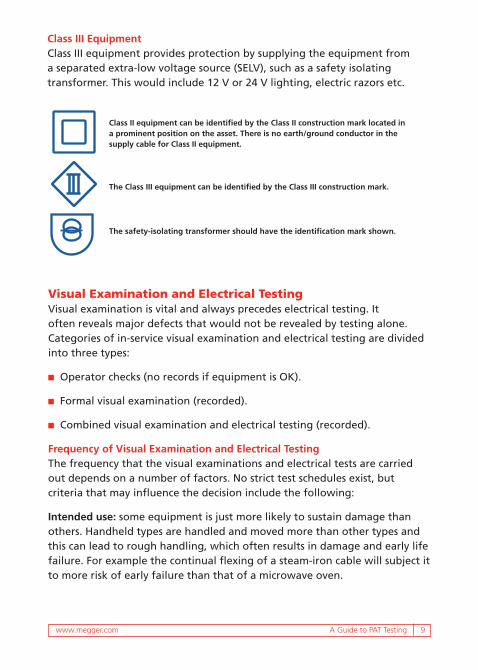
Class III EquipmentClass III equipment provides protection by supplying the equipment from a separated extra-low voltage source (SELV), such as a safety isolating transformer. This would include 12 V or 24 V lighting, electric razors etc.
The Class III equipment can be identified by the Class III construction mark.
The safety-isolating transformer should have the identification mark shown.
Class II equipment can be identified by the Class II construction mark located in a prominent position on the asset. There is no earth/ground conductor in the supply cable for Class II equipment.
Visual Examination and Electrical TestingVisual examination is vital and always precedes electrical testing. It often reveals major defects that would not be revealed by testing alone. Categories of in-service visual examination and electrical testing are divided into three types:
n Operator checks (no records if equipment is OK).
n Formal visual examination (recorded).
n Combined visual examination and electrical testing (recorded).
Frequency of Visual Examination and Electrical TestingThe frequency that the visual examinations and electrical tests are carried out depends on a number of factors. No strict test schedules exist, but criteria that may influence the decision include the following:
Intended use: some equipment is just more likely to sustain damage than others. Handheld types are handled and moved more than other types and this can lead to rough handling, which often results in damage and early life failure. For example the continual flexing of a steam-iron cable will subject it to more risk of early failure than that of a microwave oven.
10 A Guide to PAT Testing
Surroundings: equipment installed on a construction site is more likely to suffer physical damage (and will degrade more quickly) than if installed in an office, and will require frequent testing.
Design: The safety of Class II equipment does not rely on the supply earth, but on its own construction. Therefore, if Class II equipment is situated in a low-risk environment such as an office, electrical testing (not visual examination for cable or casing damage) may be reduced in frequency. Class I equipment, however, relies on a low resistance path to the supply earthing/grounding system for safety protection. If the earth conductor within the power cable is damaged, the hazard rises and will, therefore, require electrical testing on a more regular basis.
Operators: If the equipment is likely to receive constant unreported abuse, more frequent testing will be required. If the equipment users are observant, aware and responsibly report faults/damage as it occurs, hazards are more likely to be avoided and test frequency reduced.
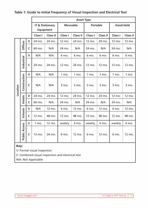
Table 1 provides guidance on initial frequencies of visual examination and electrical testing. However, this is only a guide; experience will lead the tester to determine correct frequencies.
The frequency of visual examinations and electrical tests must be regularly reviewed. Particular attention must be paid to these initial inspections and electrical tests to determine whether the frequency or equipment type needs to be changed.
Operator Checks (Procedure)All users of equipment must understand how important operator checks are. Some equipment and environments may demand special needs but generally the following list is a typical checklist that operators should be using.
1. Check the overall condition of the equipment for cracks/damage.
2. Check the supply cable, checking for cuts, abrasions, cracks, etc.
3. Look for signs of overheating.
4. Check it has a valid label indicating it has been formally inspected and tested.
5. Check the item is suitable for the environment.
www.megger.com A Guide to PAT Testing 11
Table 1: Guide to Initial Frequency of Visual Inspection and Electrical Test
Asset Type
IT & Stationary
Equipment
Moveable Portable Hand-Held
Class I Class II Class I Class II Class I Class II Class I Class II
Loca
tio
n
Offi
ces V 24 mo. 24 mo. 12 mo. 24 mo. 12 mo. 24 mo. 12 mo. 12 mo.
C 60 mo. N/A 24 mo. N/A 24 mo. N/A 24 mo. N/A
Ind
ust
rial V N/A N/A 6 mo. 6 mo. 6 mo. 6 mo. 6 mo. 6 mo.
C 24 mo. 24 mo. 12 mo. 24 mo. 12 mo. 12 mo. 12 mo. 12 mo.
Co
nst
ruct
ion V N/A N/A 1 mo. 1 mo. 1 mo. 1 mo. 1 mo. 1 mo.
C N/A N/A 3 mo. 3 mo. 3 mo. 3 mo. 3 mo. 3 mo.
Ho
tels V 24 mo. 24 mo. 12 mo. 24 mo. 12 mo. 24 mo. 12 mo. 12 mo.
C 60 mo. N/A 24 mo. N/A 24 mo. N/A 24 mo. N/A
Sch
oo
ls V N/A 12 mo. 6 mo. 12 mo. 6 mo. 12 mo. 6 mo. 12 mo.
C 12 mo. 48 mo. 12 mo. 48 mo. 12 mo. 48 mo. 12 mo. 48 mo.
Pub
lic A
cces
s V 1 mo. 12 mo. weekly 6 mo. weekly 6 mo. weekly 6 mo.
C 12 mo. 24 mo. 6 mo. 12 mo. 6 mo. 12 mo. 6 mo. 12 mo.
Key:
V: Formal visual inspection
C: Combined visual inspection and electrical test
N/A: Not Applicable

12 A Guide to PAT Testing
6. Check the plug and make sure the cable is securely gripped and there is no mechanical damage.
7. Check that the ground pin has not been removed.
8. Check the socket outlet to make sure there are no signs of damage or overheating.
9. Check that the appliance is working correctly and as expected.
If the operator is not happy with any of the above then the following actions must be taken:
1. Switch off and disconnect from the supply.
2. Clearly label to identify that it must not be used.
3. Report to the appropriate responsible person.
Note: Once equipment has been reported faulty, the responsible person will have to make a judgment as to whether the equipment is suitable for both its use and the environment it is in. More frequent inspection and testing is not the solution to unsuitable equipment.
Formal Visual Inspection (Procedure)This type of inspection should only be carried out by a competent person as defined in OSHA regulation 1926 Subpart K. The results of the formal visual examination should be documented. There are a number of things to consider when carrying out formal recorded visual examination of equipment.
1. The surroundings: the working environment plays a major part in the selection of appropriate equipment. Selecting the wrong equipment for its surroundings can have a detrimental effect on its life. For example, special consideration should be given to equipment for use where it will be exposed to the weather and natural hazards, extreme temperatures, high or low pressure, wet, dirty or corrosive conditions, solvents, mechanical or physical damage and flammable substances.
2. Good housekeeping: this covers several areas, but most of it is logical common sense. The following is a guide to what should be checked:
www.megger.com A Guide to PAT Testing 13
n Adequate space around the equipment for ventilation/cooling.
n Easily accessible means of disconnection/isolation from the supply.
n The equipment is operated with all protective covers located correctly and any interlocks operational.
n There are no unprotected cable runs under carpets.
n Minimum use of extension cords and multiway adapters.
n Cables are not located where they are likely to be damaged or create trip hazards.
n Drinks, plants and work materials are not placed where they could spill into equipment.
3. Equipment suitability: if the equipment that is being tested/inspected is unsuitable for either the environment or the purpose it is being used for, this fact should be recorded on the documentation and brought to the attention of the client.
4. Disconnection/isolation of equipment: in normal circumstances, operators must be able to reach the plug/socket without difficulty and disconnect/isolate. Isolation is simplest when the equipment is connected via a plug and socket. Not all equipment will be connected in this way and isolation may be achieved via a main switch or removal of a fuse. Caution must be exercised when inspecting equipment without the usual plug/socket arrangement. When inspecting business, IT and telecommunications equipment, permission from the equipment operator should be gained before disconnecting from the supply. Failure to do this could result in serious loss of business data. It should also be noted that business equipment might need to be powered down in the correct manner before isolation. Equipment supplied by an uninterruptible power supply (UPS) must be isolated from its standby source before any electrical testing begins. This is best performed by the system owner if there is any doubt as to the correct procedure.
5. Equipment condition: before beginning any equipment inspection, operators should be asked if they are aware of any faults and whether the equipment is functioning as expected.
14 A Guide to PAT Testing
The formal visual examination should involve similar checks to those undertaken by the operator. The following items need to be inspected:
The power cablen Is it in good condition?
n Is it free from physical damage, wear and tear?
n Is it in a position where it could be damaged (by chair casters, desk legs etc.)?
n Is it a suitable length?
n Does it have adequate strain-relief and is the insulation sheath clamped sufficiently at the terminations?
The cable-outlet or wall-socketn Is it free from cracks or damage?
n Is there any sign of overheating?
The assetn Does it work?
n Does it switch on/off correctly?
n Is it free from cracks and damage that could cause a hazard?
n Can it be used safely?
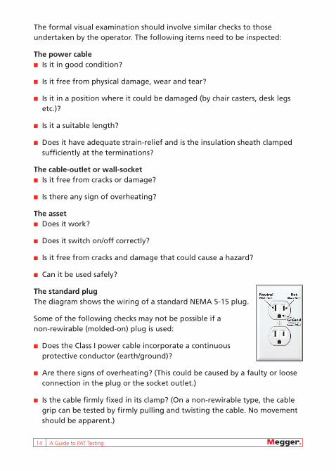
The standard plug The diagram shows the wiring of a standard NEMA 5-15 plug.
Some of the following checks may not be possible if a non-rewirable (molded-on) plug is used:
n Does the Class I power cable incorporate a continuous protective conductor (earth/ground)?
n Are there signs of overheating? (This could be caused by a faulty or loose connection in the plug or the socket outlet.)
n Is the cable firmly fixed in its clamp? (On a non-rewirable type, the cable grip can be tested by firmly pulling and twisting the cable. No movement should be apparent.)
www.megger.com A Guide to PAT Testing 15
n Are the cable core terminations tight and the plug correctly wired?
n If a fuse is fitting, is it secure with no signs of overheating? Is it of the correct type and correct rating?
The fuse should be BS 1362 approved. Also check the rating; it is usual that an appliance up to 700 W should have a 3 A fuse (colored red). Appliances larger than 700 W should have a 13 A fuse (colored brown). Some IT equipment may have a 5 A fuse fitted; however, this is less common.
Environment/usen Is the equipment suitable for the environment in which it is being used?
n Is the equipment being used for the correct purpose?
n Is the user satisfied with the equipment?
Combined Visual Examination and Electrical Testing ProcedureIf carried out correctly, formal visual examinations will reveal most (but not all) potentially dangerous faults. However, some internal deterioration of the cable, its terminals, and the equipment itself can be expected after significant use. Additionally, equipment may be misused or abused to the extent that it may give rise to danger. Electrical testing, together with a thorough visual examination, can detect faults such as loss of ground integrity, i.e. broken earth/ground (CPC - circuit protective conductor) within a flexible cable, or deterioration of insulation integrity or contamination of internal and external surfaces. Lack of insulation could result in the operator receiving an electric shock with potentially fatal results.
Initial examination This activity is a vital part of the testing process, and many faults are found at this stage. The nature of these faults is such that they will not always be found with electrical testing alone. The procedure for initial examination is as follows:
1. Obtain permission from the responsible person and disconnect any business equipment communications cords. Do not test business equipment that is still connected to communications links as it may damage other remote equipment. Care should be taken when handling fiber optic links as they may be ‘live’ from remote equipment and cause retina damage. Fit dust caps to disconnected fiber links.
16 A Guide to PAT Testing
2. Identify if the equipment can be powered down and isolated from the supply. If permission cannot be obtained then electrical tests cannot be performed. If it cannot be disconnected, perform as much visual examination as is possible without compromising your safety or the operation of the equipment. Record any defects and the fact that the equipment has not been electrically tested, and label it as such.
3. Thoroughly examine the asset for any signs of damage during a visual examination, including the power cable, plug and wall connection (socket or flex outlet).
4. Judge the suitability of the appliance for the application and surroundings.
Note: Standard new NEMA 15-5 plugs (molded-on or re-wirable) must conform to the latest NEMA standards. This legislation only applies to new plugs, not old plugs already in use. However, it would be worth noting on the visual examination notes that the plug is not to the latest regulation.
Test procedures Megger portable appliance testers are designed to test standard equipment that is supplied by plug and socket connection. This is done simply by unplugging the equipment and plugging it into a Megger portable appliance tester.
An insulation/continuity tester can test equipment that is permanently connected to a flex outlet with the test leads connected directly to the accessory terminals. However, to carry out this method the person performing the test would need additional relevant competencies. An alternative method is to temporarily connect the asset to a NEMA 15-5 and test conventionally using the portable appliance tester.
Electrical TestsBefore any in-service electrical testing can be carried out, a preliminary inspection should have been performed. The electrical testing then consists of the following in this specific order: 1. Earth continuity or bond tests 2. Insulation resistance testing (if a 500 V insulation test is not appropriate, this can be replaced by a touch current or alternative leakage current test) 3. Functional Checks

www.megger.com A Guide to PAT Testing 17
Some test equipment is capable of performing tests that in certain circumstances could damage the appliance they are used on. Flash testing (also known as hi-pot or dielectric strength testing) is one such test and is only normally carried out by manufacturers or when an appliance has had a deep overhaul.
Earth Bond/Continuity TestEarth bond/continuity tests only apply to Class I equipment and are used to confirm the existence of a safety return path. The purpose of the test is to ensure that the ground terminal has a low resistance connection to the conductive metal casing of the appliance. An effective connection to the system ground within the fixed installation of the premises ensures safety.
There are two methods available and different circumstances will require each method:
1. Low current continuity test: A continuity measurement should be made using a short circuit test current between 20-200 mA between exposed conductive parts of the equipment and the earth pin of the plug (or earth/ground-terminal of the supply). This test is performed using the earth bond lead. The maximum value of resistance should be noted while flexing the asset supply cable and a visual examination of the power cable terminations at both ends should be made. Any fluctuation in the reading should be investigated to identify the cause. The test current is so low that there is no risk of damaging earth connections that may exist for functional, rather than safety, reasons. This low-current test is sometimes referred to as a “soft test.”
2. High current bond test: a continuity measurement using a test current of max 26 A for between 5 to 20 seconds. This test is used where the user has concerns that a ground may be maintained by a few strands of wire or where poor surface contact by the probes or clips could give a misleading reading. The bond test should be connected between exposed earthed/grounded conductive parts of the equipment and the ground pin of the plug (or ground-terminal of the supply). This is done by connecting the earth bond lead to the exposed metalwork. The maximum value of resistance should be noted while flexing the asset supply cable and a visual examination of the power cable terminations at both ends should be made. Any fluctuation in the reading should be investigated to identify the cause.
Graphic here for pic of iron
18 A Guide to PAT Testing
Care should be taken when measuring ground bond on appliances where the design of construction includes exposed metalwork having a casual contact to earth. This metalwork is primarily protected by double or reinforced insulation, and the ground connection is only classed as ‘fortuitous’. Under these circumstances, the resistance value is unlikely to be as low as truly bonded metalwork. A bond test performed on this unbonded metalwork may give unexpected or misleading results. Examples of this construction may include the sole plate of a steam iron or the metal chassis of a coffee maker. Additionally, a high-current bond test using up to 26 A may, in some circumstances, damage casual contact components and a low-current test should be performed first to identify potential issues. Table 2 indicates the limits of the earth bond test.
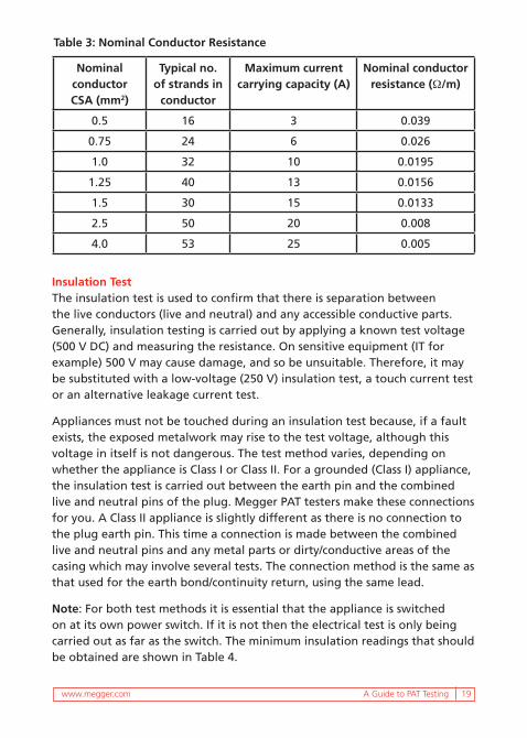
For manual verification, or if the resistance R of the protective conductor of the power cable cannot easily be measured, the information in Table 3 provides nominal cable resistances per meter length for various types of flexible cable. The supply cable should first be identified and the length measured. The resistance of the protective conductor can then be calculated by multiplying the nominal resistance by the length.
The bond test may fail due to the excessive length of the equipment supply cord. Extension cords may also fail due to increased resistance induced by long cable lengths.
For appliances with a supply cord
For appliances with a power cable (3 core); extension cords, multiway and GFCI adapters
0.1 Ω(0.1 + R) Ω where R is the resistance of the protective conductor of the supply cable
Table 2: Earth Bond Limits
www.megger.com A Guide to PAT Testing 19
Nominal conductor CSA (mm2)
Typical no. of strands in
conductor
Maximum current carrying capacity (A)
Nominal conductor resistance (Ω/m)
0.5 16 3 0.039
0.75 24 6 0.026
1.0 32 10 0.0195
1.25 40 13 0.0156
1.5 30 15 0.0133
2.5 50 20 0.008
4.0 53 25 0.005
Table 3: Nominal Conductor Resistance
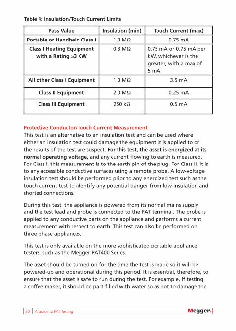
Insulation TestThe insulation test is used to confirm that there is separation between the live conductors (live and neutral) and any accessible conductive parts. Generally, insulation testing is carried out by applying a known test voltage (500 V DC) and measuring the resistance. On sensitive equipment (IT for example) 500 V may cause damage, and so be unsuitable. Therefore, it may be substituted with a low-voltage (250 V) insulation test, a touch current test or an alternative leakage current test.
Appliances must not be touched during an insulation test because, if a fault exists, the exposed metalwork may rise to the test voltage, although this voltage in itself is not dangerous. The test method varies, depending on whether the appliance is Class I or Class II. For a grounded (Class I) appliance, the insulation test is carried out between the earth pin and the combined live and neutral pins of the plug. Megger PAT testers make these connections for you. A Class II appliance is slightly different as there is no connection to the plug earth pin. This time a connection is made between the combined live and neutral pins and any metal parts or dirty/conductive areas of the casing which may involve several tests. The connection method is the same as that used for the earth bond/continuity return, using the same lead.
Note: For both test methods it is essential that the appliance is switched on at its own power switch. If it is not then the electrical test is only being carried out as far as the switch. The minimum insulation readings that should be obtained are shown in Table 4.
20 A Guide to PAT Testing
Protective Conductor/Touch Current MeasurementThis test is an alternative to an insulation test and can be used where either an insulation test could damage the equipment it is applied to or the results of the test are suspect. For this test, the asset is energized at its normal operating voltage, and any current flowing to earth is measured. For Class I, this measurement is to the earth pin of the plug. For Class II, it is to any accessible conductive surfaces using a remote probe. A low-voltage insulation test should be performed prior to any energized test such as the touch-current test to identify any potential danger from low insulation and shorted connections.
During this test, the appliance is powered from its normal mains supply and the test lead and probe is connected to the PAT terminal. The probe is applied to any conductive parts on the appliance and performs a current measurement with respect to earth. This test can also be performed on three-phase appliances.
This test is only available on the more sophisticated portable appliance testers, such as the Megger PAT400 Series.
The asset should be turned on for the time the test is made so it will be powered-up and operational during this period. It is essential, therefore, to ensure that the asset is safe to run during the test. For example, if testing a coffee maker, it should be part-filled with water so as not to damage the
Pass Value Insulation (min) Touch Current (max)
Portable or Handheld Class I 1.0 MΩ 0.75 mA
Class I Heating Equipment with a Rating ≥3 KW
0.3 MΩ 0.75 mA or 0.75 mA per kW, whichever is the greater, with a max of 5 mA
All other Class I Equipment 1.0 MΩ 3.5 mA
Class II Equipment 2.0 MΩ 0.25 mA
Class III Equipment 250 kΩ 0.5 mA
Table 4: Insulation/Touch Current Limits
www.megger.com A Guide to PAT Testing 21
element during this test. It should also be noted that if testing a drill, or other appliance with moving parts, a potential hazard may exist while the drill is energized and machinery rotating.
The current is measured within five seconds after the application of the test voltage (usually the supply voltage); the values must not exceed those given as shown in Table 4.
Differential Leakage TestThe differential leakage current (also called protective conductor current) test measures the difference in current between the live and neutral conductors and determines if any current is flowing to earth. Normally, appliances should have no, or very little, earth leakage current. Class II (double insulated) appliances could exhibit earth leakage through their mountings or by operator contact.
During the test, the actual mains voltage is measured at the appliance socket. To ensure that the equipment is safe even when the mains supply rises to its maximum permitted value, the PAT calculates and displays the leakage current that would flow at this value.
Substitute/Alternative Leakage TestThe substitute leakage test measures the leakage current in the earth conductor using a low ac voltage (typically 40 Vac). This approach reduces the risk of electric shock and prevents the equipment from running during the test. The test socket is optional, as this test is independent of the supply voltage. The measured value is adjusted to reflect the worst leakage current at the upper operating voltage limit.
For Class I equipment, the appliance has its phase conductors joined together within the PAT and a 40 V supply is applied between both phase conductors and the protective conductor connection of the equipment under test. In the case of Class II equipment, the test lead and probe are connected to the item under test.
The probe is applied to any conductive parts on the appliance under test. The actual voltage is measured at the appliance socket. From these readings, the earth leakage current of the appliance is calculated and scaled depending on the appliance supply voltage.
22 A Guide to PAT Testing
Load TestThe load test (also called the operational or VA test) measures the power consumption of the equipment when running. Measuring the load (VA) of an appliance is a good indication of its operating condition. By setting a load VA limit in the instrument’s test groups, an appliance can be assessed automatically for excessive load. The load VA limit is usually set based on the rating plate on the appliance.
When using the Megger portable appliance testers, which power up the equipment for you, a functional test is carried out during the “load” test. This test will determine:
n If the asset functions correctly
n The VA rating of the appliance
The results of this test can be a good indicator of future problems and potential failures in an appliance. Problems like worn bearings on a drill would probably result in increased current drawn from the supply and therefore an increase in the VA reading.
Care should be exercised when electrical testing equipment with suspected high leakage currents as substantial electric shocks can be received from exposed conductive parts and/or the ground terminal if the appliance is not adequately grounded. Whenever high leakage currents are present a warning label like the one below should be displayed adjacent to the primary power connections.
WARNING HIGH PROTECTIVE CONDUCTOR CURRENT Earth connection essential before connecting the supply
The reason that the cord set should be inspected and tested separately is that the cord set could be used to supply a different appliance. A 2-core cord set should not be fitted with a 3-pole appliance coupler.
Power Cables and Leads Appliances with detachable power supply flexes (such as electric lawn mowers) should be electrically tested with the cable plugged into the appliance as a complete assembly. The cable should then be labelled and tested again, separately from the appliance. A 3-core cable should be tested as a Class I appliance, with a visual examination and earth bond, polarity
www.megger.com A Guide to PAT Testing 23
and insulation tests. A 2-core cable should be tested as a Class II appliance, with a visual examination and polarity and insulation tests.
The reason the cable is examined and tested again separately from the asset is that the cable could potentially be used to supply a different appliance.
A 2-core cable should not be fitted with a 3-pole connector.
Extension cords If extension cords have a normal 3-pin socket outlet, it is essential that a protective conductor exist in the cable. Class II extension cords are dangerous and should not be used. The code of practice recommends maximum extension cord lengths, which should not exceed the lengths as indicated in Table 5.
Conductor CSA 1.25 mm2 1.5 mm2 2.5 mm2
Max Length 39 ft (12 m) 49 ft (15 m) 82 ft (25 m)
Table 5: Extension Cord Lengths
Flash TestingFlash testing measures the leakage current when high test voltages are applied to an asset. The flash test provides a high ac test voltage (2500 V or 3000 V) and measures the leakage current. This test can be destructive and is usually only used on equipment that has been repaired. It is not generally used for “in-service testing” of electrical equipment.
Faulty or Damaged EquipmentIf you find damaged or faulty equipment then this should be labelled, and if unsafe removed from service, and brought to the attention of the client. They need to make a judgment on whether the equipment is suitable for both the environment in which it is being used and the application to which it is being put. If the person assesses that it is unsuitable for either of these reasons it has to be replaced with more suitable equipment.
Missing EquipmentItems of equipment on the test register that are not where they are expected to be should be brought to the attention of the client.

24 A Guide to PAT Testing
LabellingAny equipment that requires visual examination and electrical testing must be clearly labelled. The label must consist of a unique identifier for the equipment, the date it was tested, the re-test date and an indication of its state. A failed asset does not need the dates on, just clear identification that it has failed.
Labels may either be filled in by hand or printed. Printed labels often consist of a bar code for the identifier making them easy to read with a suitable barcode scanner. This is a great time saver with an instrument that supports it such as the PAT400 Series by Megger.
Labels should be manufactured so they can be applied to a variety of surfaces. They should be tough and capable of lasting until the next retest date. In harsh environments it may be necessary to apply additional protection in the form of clear vinyl covers.
DocumentationAs best practice, the following records should be established and maintained:
n A register of all equipment
n A record of formal and combined visual examinations and electrical tests
n A register of all faulty equipment
n A repair register
All of these records can be stored on paper or electronically, as long as reasonable precautions are taken with regard to the safeguarding of the data. Whichever method is chosen, previous test results must be available to the test operative.
The company carrying out the testing should maintain the following paper or electronic records:
n Copy of the formal visual examination and combined visual examination and electrical test results
n Register of all equipment repaired
www.megger.com A Guide to PAT Testing 25
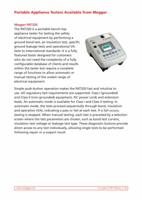
Megger PAT320The PAT320 is a portable bench-top appliance tester for testing the safety of electrical equipment by performing a ground bond test, an insulation test, specific ground leakage tests and operational VA tests to international standards. It is a fully featured tester designed for customers who do not need the complexity of a fully configurable database of clients and results within the tester but require a complete range of functions to allow automatic or manual testing of the widest range of electrical equipment.
Simple push-button operation makes the PAT320 fast and intuitive to use. All regulatory test requirements are supported: Class I (grounded) and Class II (non-grounded) equipment, IEC power cords and extension leads. An automatic mode is available for Class I and Class II testing. In automatic mode, the tests proceed sequentially through bond, insulation and operation (VA), indicating a pass or fail at each test. If a fail occurs, testing is stopped. When manual testing, each test is preceded by a selection screen where the test parameters are chosen, such as bond test current, insulation test voltage or leakage test type. These diagnostic buttons provide direct access to any test individually, allowing single tests to be performed following repair or a suspect result.
Portable Appliance Testers Available from Megger

26 A Guide to PAT Testing
Megger PAT450Operators of electric tools and other electrical equipment must be protected from potentially dangerous flaws in workmanship or wear and tear. The PAT450 is designed to test portable electrical equipment for safe operation. The tests conform to the latest editions of European regulations and standards including VDE0701/0702 and the Code of Practice for the In-Service Inspection and Testing of Electrical Equipment in the UK.
All standard PAT tests are available which include the following:
n Earth bond at 200 mA, 10A and 25A (suitable for all equipment including IT)
n Insulation at 250 V and 500 V
n Polarity for extension lead testing,
n Full load (VA)
n Alternative leakage tests (substitute, differential and touch current)
n 1.5 kV and 3 kV flash, or dielectric strength tests
The PAT450 is the ideal instrument for companies who engage in portable appliance testing and have a requirement to customize and adapt testing routines to their own requirements, and where the level is such that on-board storage and asset management is seen as a requirement beyond simple manual testing. The PAT450 has fully customizable and configurable test groups with selectable PASS/FAIL limits, and on-board storage for 10,000 asset records.

UNITED STATES Megger Valley Forge 2621 Van Buren Avenue Norristown, PA 19403 866-254-0962
PATGuide_en_V01
Megger makes high quality instruments for the following electrical testing applications:
n Insulation Testing
n Relay Testing
n Oil Testing
n Circuit Breaker Testing
n Power Quality Analysis
n Low Resistance Testing
Megger manufactures electrical test and maintenance instruments for electrical power, process manufacturing, building wiring, engineering services and communications.
Visit our website for local assistance worldwide at www.megger.com.
n Battery Testing
n Watthour Meter Testing
n Transformer Testing
n Cable Fault Locating
n Power Factor Testing
n Hi Pot Testing