MegaPowerTM LT Matrix Switcher/Controller System · MegaPowerTM LT Matrix Switcher/Controller...
84
MegaPower TM LT Matrix Switcher/Controller System ADMPLT16 ADMPLT32 ADMPLT16C2 ADMPLT16C3 ADMPLT32C2 ADMPLT32C3 Installation and Operation Instructions
Transcript of MegaPowerTM LT Matrix Switcher/Controller System · MegaPowerTM LT Matrix Switcher/Controller...

MegaPowerTM LTMatrix Switcher/Controller System
ADMPLT16ADMPLT32
ADMPLT16C2ADMPLT16C3ADMPLT32C2ADMPLT32C3
Installation and Operation Instructions
ii
MegaPower LT
NoticeThe information in this manual was current when published. The manufacturer reserves the right to
revise and improve its products. All specifications are therefore subject to change without notice.
CopyrightUnder copyright laws, the contents of this manual may not be copied, photocopied, reproduced,translated or reduced to any electronic medium or machine-readable form, in whole or in part,without prior written consent of American Dynamics Video Products Division.
© Copyright 2003
American Dynamics Video Products Division
6795 Flanders Drive San Diego, CA 92121 U.S.A.
TrademarksMegaPower™ is a trademark of American Dynamics Video Products Division.
Trademarked names are used throughout this manual. Rather than place a symbol at each occurrence,trademarked names are designated with initial capitalization. Inclusion or exclusion is not a judgmenton the validity or legal status of the term.
Important InformationBefore proceeding, please read and observe all instructions and warnings contained in this manual.Retain this manual with the original bill of sale for future reference and, if necessary, warrantyservice.
When unpacking your new American Dynamics product, check for missing or damaged items. Ifany item is missing, or if damage is evident, DO NOT INSTALL OR OPERATE THIS PRODUCT.Contact your dealer for assistance.
NOTE
This product is supplied with a printed English manual. The manual is also provided in other
languages (French, Spanish and German) on the included CD.
For your RecordsComplete the following product purchase information. The factory requests this information when
contacted for technical support. It is also valuable in case of loss or theft.
Purchase Date: __________________________
Serial Number: __________________________

iii
Matrix Installation and Operation
INSTALLATION IS ONLY TO BE CARRIED OUT BY COMPETENT, QUALIFIED AND EXPERIENCED PERSONNEL.WIRE IN ACCORDANCE WITH COUNTRY OF INSTALLATION NATIONAL WIRING REGULATIONS.
ACCESS CAN ONLY BE GAINED BY SERVICE PERSONS. THERE ARE NO USER-ACCESS AREAS. ACCESSBY SERVICE PERSONS CAN ONLY BE GAINED BY THE USE OF AN APPROPRIATE TOOL.
THE EQUIPMENT SUPPLIED WITH THIS MANUAL IS DESIGNED FOR USE IN GENERAL PURPOSE CCTVINSTALLATION AND HAS NO OTHER FUNCTION. DO NOT EXCEED THE VOLTAGE AND TEMPERATURELIMITS GIVEN IN THE SPECIFICATIONS. ONLY USE YOUR MATRIX IN A CLEAN, DRY, DUST-FREEENVIRONMENT.
TO REDUCE RISK OF ELECTRIC SHOCK, DO NOT REMOVE COVER. NO USER SERVICEABLE PARTS INSIDE.REFER SERVICING TO QUALIFIED SERVICE PERSONNEL.
TO PREVENT FIRE OR SHOCK HAZARD, DO NOT EXPOSE THIS APPLIANCE TO RAIN OR MOISTURE.
THE MEGAPOWER LT MUST ONLY BE POWERED BY THE CLASS 2 INSULATED UL LISTED 15 WATT LPSSUPPLY (MP-PSU) PROVIDED.
POWER ISOLATION MUST BE PROVIDED VIA THE: PLUG; APPLIANCE COUPLER; ISOLATING SWITCH;CIRCUIT BREAKER, OR AN EQUIVALENT ELECTRICAL DEVICE IN CLOSE PROXIMITY TO THE EQUIPMENT.
A 3 AMP FUSE IN THE UK PLUG PROVIDES PROTECTION AGAINST OVERLOAD AND SHORT CIRCUIT. INAREAS WHERE A UK PLUG IS NOT APPROPRIATE, SIMILIAR PROTECTION MUST BE PROVIDED IN THEINSTALLATION.
Electrical SafetyBritish Standard BSEN60950:2001 Safety of information technology equipment Including electrical businessequipment.
Underwriters Laboratories Inc. UL1950 Safety of information technology equipment, including electrical businessequipment.Canadian Standards Association CAN/CSA C22.2 No. 950-95.
Radio Frequency EmissionsBritish Standard EN50081-1:1992 Electromagnetic compatibility - Emission. Part 1. Residential, commercial andlight industry.
British Standard BSEN55022:1998 Limits and methods of measurement of radio disturbance characteristics ofinformation technology equipment.
ImmunityBritish Standard BSEN50130-4 Alarm Systems Part 4 Electromagnetic compatibility Product family standard: Im-munity requirements for components of fire, intruder and social alarm systems.
EU Conformance StatementA Declaration of Conformity in accordance with the above EU standards has been made and is on file with themanufacturer. The manufacturer declares that the product supplied with this document is complaint with the provi-sions of the EMC Directive 89/336 EEC, the Low Voltage Directive LVD 73/23 EEC, the CE Marking Directive 93/68EEC and all associated amendments.
Regulatory NoticesThis device complies with part 15 of the FCC rules. Operation is subject to the following two conditions: (1) Thisdevice may not cause harmful interference, and (2) this device must accept any interference received, includinginterference that may cause undesired operation.

iv
MegaPower LT
L’INSTALLATION NE SAURAIT ÊTRE EFFECTUÉE QUE PAR UN PERSONNEL QUALIFIÉ ET EXPÉRIMENTÉ. BRANCHERET RACCORDER EN CONFORMITÉ AVEC LES RÉGLEMENTATIONS EN VIGUEUR DANS LE PAYS OÙ EST INSTALLÉEL’UNITÉ.
L’ACCÈS NE PEUT ÊTRE OBTENU QUE PAR LES TECHNICIENS DE MAINTENANCE. L’ACCÈS DOIT ÊTRESTRICTEMENT INTERDIT À TOUT UTILISATEUR. L’ACCÈS PAR LES TECHNICIENS DE MAINTENANCE NE PEUTÊTRE EFFECTUÉ QU’À L’AIDE D’UN OUTIL APPROPRIÉ.
L’ÉQUIPEMENT FOURNI AVEC LE PRÉSENT MANUEL EST CONÇU POUR ÊTRE UTILISÉ DANS LE CADRE GÉNÉRALDE LA SURVEILLANCE PAR CAMÉRA À CIRCUIT FERMÉ (CCTV) ET N’A AUCUNE AUTRE FONCTION. NE PASDÉPASSER LES SEUILS DE TENSION ET DE TEMPÉRATURE INDIQUÉS DANS LES CARACTÉRISTIQUESTECHNIQUES. N’UTILISER L’UNITÉ MATRIX QU’EN ENVIRONNEMENT PROPRE, SEC ET EXEMPT DE POUSSIÈRE.
POUR RÉDUIRE LES RISQUES D’ÉLECTROCUTION, NE PAS DÉPOSER LE COUVERCLE. AUCUN COMPOSANT NEPEUT ÊTRE RÉPARÉ PAR L’UTILISATEUR. FAIRE APPEL À UN TECHNICIEN DE MAINTENANCE COMPÉTENT.
POUR PRÉVENIR TOUT RISQUE D’INCENDIE OU D’ÉLECTROCUTION, NE PAS EXPOSER CETTE UNITÉ À LA PLUIENI À L’HUMIDITÉ.
L’UNITÉ MEGAPOWER LT DOIT ÊTRE ALIMENTÉE PAR LE GROUPE DE CLASSE 2 UL ISOLÉ 15 WATTS (MP-PSU)FOURNI.
L’ISOLATION DOIT ÊTRE ASSURÉE PAR LE BIAIS DE LA PRISE, DU COUPLEUR DE L’UNITÉ, DU COMMUTATEURISOLANT, DU FUSIBLE PI DE TOUT DISPOSITIF ÉLECTRIQUE ÉQUIVALENT À PROXIMITÉ RAPPROCHÉE DE L’UNITÉ.
UN FUSIBLE DE 3 A DANS LA PRISE BRITANNIQUE ASSURE LA PROTECTION CONTRE LES SURCHARGES ET LESCOURTS-CIRCUITS. DANS LES PAYS OÙ UNE PRISE BRITANNIQUE NE CONVIENT PAS, UNE PROTECTION SIMILAIREDOIT ÊTRE APPORTÉE LORS DE L’INSTALLATION.
Sécurité électriqueNorme britannique BSEN60950:2001 : sécurité des équipements informatiques, notamment les équipements électriquescommerciaux.
Underwriters Laboratories Inc. UL1950 – Sécurité des équipements informatiques, y compris les équipements électriques àusage professionnel.
Canadian Standards Association CAN/CSA C22.2 No. 950-95.
Émission de fréquences radioNorme européenne EN50081-1:1992 – Compatibilité électromagnétique - Émissions. Section 1. Usage résidentiel, commercialet industriel limité.
Norme britannique BSEN55022:1998 : limites et méthodes de mesure des caractéristiques de perturbation radio deséquipements informatiques.
ImmunitéNorme britannique BSEN50130-4 : systèmes d’alarme, 4e partie, compatibilité électromagnétique Norme de famille de produits :caractéristiques d’immunité des composants des systèmes anti-incendie, anti-intrusion et d’alarme sociaux.
Déclaration de conformité UEUne déclaration de conformité aux normes ci-dessus de l’Union européenne a été réalisée et est conservée chez le constructeur.Le constructeur déclare le produit accompagnant ce document conforme aux dispositions de la Directive 89/336 de la CEEsur la compatibilité électromagnétique, de la directive LVD 73/23 de la CEE sur les basses tensions et de la Directive 93/68de la CEE et ses modifications sur la marque CE.
Avis réglementairesCet équipement est conforme au paragraphe 15 des réglementations de la FCC. Son utilisation est sujette aux deux conditionssuivantes : (1) cet équipement ne doit pas générer d’interférences nuisibles et (2) cet équipement doit accepter les interférenceséventuelles, notamment les interférences susceptibles de provoquer un fonctionnement indésirable.
v
Matrix Installation and Operation
DIE INSTALLATION DARF NUR VON KOMPETENTEM, QUALIFIZIERTEM UND ERFAHRENEM PERSONAL AUSGEFÜHRTWERDEN. DIE VERKABELUNG MUSS GEMÄSS DER AM INSTALLATIONSORT GELTENDEN, NATIONALENVERKABELUNGSVORSCHRIFTEN ERFOLGEN.
DER ZUGRIFF IST NUR DEM WARTUNGSPERSONAL MÖGLICH. ES SIND KEINE BENUTZERZUGÄNGLICHENBEREICHE VORHANDEN. DER ZUGRIFF DURCH DAS WARTUNGSPERSONAL IST NUR MIT HILFE EINES GEEIGNETENWERKZEUGS MÖGLICH.
DIE ZUSAMMEN MIT DIESEM HANDBUCH GELIEFERTE AUSRÜSTUNG IST FÜR DEN GEBRAUCH IN ALLGEMEINENCCTV-ANLAGEN KONZIPIERT UND DIENT KEINEM ANDEREN ZWECK. DIE IN DEN TECHNISCHEN DATENANGEGEBENEN SPANNUNGS- UND TEMPERATURGRENZEN DÜRFEN NICHT ÜBERSCHRITTEN WERDEN. DIESCHALTMATRIX DARF NUR IN EINER SAUBEREN, TROCKENEN UND STAUBFREIEN UMGEBUNG VERWENDETWERDEN.
UM DAS RISIKO VON STROMSCHLAG ZU REDUZIEREN, DARF DIE ABDECKUNG NICHT ENTFERNT WERDEN. DASGERÄT ENTHÄLT KEINE DURCH DEN BENUTZER WARTBARE TEILE. WARTUNGSARBEITEN DÜRFEN NUR VONQUALIFIZIERTEM WARTUNGSPERSONAL DURCHGEFÜHRT WERDEN.
ZUM SCHUTZ GEGEN BRAND- ODER STROMSCHLAGGEFAHR DARF DAS GERÄT KEINEM REGEN ODERFEUCHTIGKEIT AUSGESETZT WERDEN.
DAS MEGAPOWER-LT-SYSTEM DARF NUR ÜBER DIE MITGELIEFERTE, ISOLIERTE, UL-GELISTET 15-WATT-VERSORGUNG (MP-PSU) GESPEIST WERDEN.
DIE STROMVERSORGUNG MUSS MITTELS DES FOLGENDEN UNTERBROCHEN WERDEN KÖNNEN: STECKER;GERÄTEKUPPLUNG; TRENNSCHALTER; SICHERUNG ODER EINE GLEICHWERTIGE ELEKTRISCHE VORRICHTUNGIN DER NÄHE DER AUSRÜSTUNG.
EINE IM BRITISCHEN NETZSTROMSTECKER UNTERGEBRACHTE 3-AMPERE-SICHERUNG SICHERT DIEAUSRÜSTUNG GEGEN ÜBERLASTUNG UND KURZSCHLUSS. WO EIN BRITISCHER STECKER NICHT ANGEBRACHTIST, MUSS EIN ÄHNLICHER SCHUTZ ÜBER DIE INSTALLATION ERFOLGEN.
Elektrische SicherheitBritish Standard BSEN60950:2001 – Sicherheit von informationstechnischer Ausrüstung, einschließlich elektrischerGeschäftsausrüstung.
Underwriters Laboratories Inc. UL1950 Sicherheit von informationstechnischer Ausrüstung, einschließlich elektrischerGeschäftsausrüstung.
Canadian Standards Association CAN/CSA C22.2 No. 950-95.
FunkfrequenzemissionenEuronorm EN50081-1:1992 Elektromagnetische Kompatibilität – Emission. Teil 1. Wohnbereiche, kommerzielle undleichtindustrielle Umgebungen.
British Standard BSEN55022:1998 – Messgrenzen und -verfahren für Funkstörungscharakteristiken voninformationstechnischer Ausrüstung.
ImmunitätBritish Standard BSEN50130-4 – Alarmsysteme, Teil 4, elektromagnetischer Kompatibilitätsstandard für die Produktgruppe:Immunitätsanforderungen für Komponenten von Feuer-, Einbruchs- und öffentlichen Alarmsystemen.
EU-KonformitätserklärungEine Konformitätserklärung gemäß der o. g. EU-Standards ist erfolgt und liegt beim Hersteller vor. Der Hersteller erklärt,dass das mit diesem Dokument gelieferte Produkt die Anforderungen der Richtlinie für elektromagnetische Kompatibilität89/336 EEC, der Richtlinie für Niederspannung LVD 73/23 EEC, der CE-Kennzeichnungsrichtlinie 93/68 EEC und allerdiesbezüglichen Änderungen erfüllt.
Aufsichtsbehördliche HinweiseDieses Gerät entspricht Teil 15 der FCC-Richtlinien. Der Betrieb ist vorbehaltlich der beiden folgenden Bedingungen gestattet:(1) dieses Gerät darf keine schädlichen Störungen verursachen, und (2) dieses Gerät muss alle Störungen akzeptieren,einschließlich solcher, die den Betrieb beeinträchtigen könnten.
vi
MegaPower LT
L’INSTALLAZIONE DEVE ESSERE ESEGUITA ESCLUSIVAMENTE DA PERSONALE COMPETENTE, ESPERTO EQUALIFICATO. COLLEGARE I CAVI IN CONFORMITÀ ALLE SPECIFICHE NAZIONALI DI INSTALLAZIONE.
L’ACCESSO È CONSENTITO SOLTANTO AL PERSONALE ADDETTO ALLA MANUTENZIONE. NON ESISTONO AREEACCESSIBILI DA PARTE DELL’UTENZA. IL PERSONALE ADDETTO ALLA MANUTENZIONE PUÒ ACCEDERE SOLOUTILIZZANDO UNO STRUMENTO APPROPRIATO.
L’APPARECCHIO CUI QUESTO MANUALE SI RIFERISCE È DESTINATO ALL’USO IN INSTALLAZIONI GENERICHE PERTV A CIRCUITO CHIUSO E NON HA ALCUNA ALTRA FUNZIONE. NON SUPERARE I LIMITI DI VOLTAGGIO ETEMPERATURA INDICATI NELLE SPECIFICHE. USARE L’APPARECCHIO ESCLUSIVAMENTE IN AMBIENTI PULITI,NON UMIDI E NON POLVEROSI.
PER RIDURRE IL RISCHIO DI SHOCK ELETTRICI, NON RIMUOVERE IL COPERCHIO. L’INTERNO NON CONTIENEPARTI CHE L’UTENTE POSSA RIPARARE. RIVOLGERSI A TECNICI DI ASSISTENZA QUALIFICATI.
PER EVITARE IL RISCHIO DI INCENDI O SHOCK, NON ESPORRE L’APPARECCHIO ALLA PIOGGIA O ALL’UMIDITÀ.
IL SISTEMA MEGAPOWER LT DEVE ESSERE ALIMENTATO ESCLUSIVAMENTE CON L’ALIMENTATORE ISOLATO DICLASSE 2 (CERTIFICATO UL) A 15 WATT (MP-PSU) ACCLUSO.
PER L’ISOLAMENTO ELETTRICO, SERVIRSI DI: SPINA, ACCOPPIATORE DEL DISPOSITIVO, INTERRUTTOREISOLANTE, INTERRUTTORE DI CIRCUITO O DI UN DISPOSITIVO ELETTRICO EQUIVALENTE, INSTALLATO VICINOALL’APPARECCHIO,
ALL’INTERNO DELLA SPINA DI TIPO BRITANNICO È PRESENTE UN FUSIBILE DA 3 AMPERE, CHE PROTEGGE DASOVRACCARICHI E CORTI CIRCUITI. NEI PAESI IN CUI TALE SPINA NON È UTILIZZABILE, AL MOMENTODELL’INSTALLAZIONE SI DEVE PREVEDERE UNA PROTEZIONE ANALOGA.
Sicurezza elettricaStandard britannico BSEN60950:2001 per la sicurezza delle apparecchiature informatiche, incluse le apparecchiatureelettriche aziendali.
Underwriters Laboratories Inc. UL1950 per la sicurezza delle apparecchiature informatiche, incluse le apparecchiatureelettriche aziendali.
Associazione standard canadesi CAN/CSA C22.2 No. 950-95.
Emissioni in radiofrequenzaStandard europeo EN50081-1:1992, compatibilità elettromagnetica - emissioni. Parte 1. Installazioni residenziali, commercialie dell’industria leggera.
Standard britannico BSEN55022:1998 per i limiti e i metodi di misurazione delle interferenze radio caratteristiche delleapparecchiature informatiche.
InalterabilitàStandard britannico BSEN50130-4 per i sistemi di allarme, parte 4, standard di compatibilità elettromagnetica per latipologia di prodotti: requisiti di immunità per sistemi di allarme antincendio, anti-intrusione e di tipo sociale.
Dichiarazione di conformità UEIn base agli standard UE summenzionati, è stata emessa una Dichiarazione di conformità che è archiviata nella sede delproduttore. Il produttore dichiara che il prodotto fornito col presente documento è conforme alle prescrizioni della direttivaEMC 89/336 CEE, della direttiva sul basso voltaggio LVD 73/23 CEE, della direttiva sul marchio CE 93/68 CEE e di tuttele relative modifiche.
Avvisi normativiQuesto dispositivo è conforme alle norme FCC, parte 15. Il funzionamento è soggetto alle due condizioni seguenti: (1) Ildispositivo non deve causare interferenze dannose; (2) il dispositivo deve sostenere le interferenze in ingresso, inclusequelle che potrebbero determinare un funzionamento non desiderato.
vii
Matrix Installation and Operation
LA INSTALACIÓN DEBERÁ SER REALIZADA EXCLUSIVAMENTE POR PERSONAL COMPETENTE, CUALIFICADO YCON EXPERIENCIA. LAS CONEXIONES ELÉCTRICAS SE REALIZARÁN EN CONFORMIDAD CON LA NORMATIVANACIONAL EN MATERIA DE CABLEADO DE CADA PAÍS.
ACCESO SÓLO AUTORIZADO AL PERSONAL DEL SERVICIO TÉCNICO. NO HAY ZONAS DE ACCESO PARA USUARIOS.EL PERSONAL DEL SERVICIO TÉCNICO SOLAMENTE PODRÁ ACCEDER MEDIANTE EL USO DE UNA HERRAMIENTAADECUADA.
EL EQUIPO QUE SE SUMINISTRA JUNTO CON ESTE MANUAL ESTÁ DISEÑADO PARA USO EN INSTALACIONES DECCTV (CIRCUITO CERRADO DE TELEVISIÓPN) DE PROPÓSITO GENERAL Y NO TIENE OTRA FUNCIÓN. NO SUPERELOS LÍMITES DE TENSIÓN Y TEMPERATURA INDICADOS EN LAS ESPCIFICACIONES. USE LA MATRIZ SOLAMENTEEN UN AMBIENTE LIMPIO, SECO Y SIN POLVO.
CON EL FIN DE REDUCIR EL RIESGO DE DESCARGA ELÉCTRICA, EVITE RETIRAR LA CUBIERTA. EN EL INTERIORNO HAY NINGÚN COMPONENTE QUE PUEDA SER REPARADO POR EL USUARIO. CUALQUIER REPARACIÓN DEBESER REALIZADA POR PERSONAL DE SERVICIO DEBIDAMENTE CUALQUIDFICADO.
PARA EVITAR RIESGO DE INCENDIO O DESCARGA ELÉCTRICA, NO EXPONGA ESTE EQUIPO A LA LLUVIA O A LAHUMEDAD.
EL MEGAPOWER LT DEBE ALIMENTARSE EXCLUSIVAMENTE CON LA FUENTE DE ALIMENTACIÓN (MP-PSU) DE15 VATIOS, CON AISLAMIENTO INCLUIDA EN LA LISTA UL DE CLASE 2, QUE SE SUMINISTRA CON EL EQUIPO.
EL AISLAMIENTO DE LA ALIMENTACIÓN DEBE REALIZARSE POR MEDIO DE: CONECTOR; ACOPLADOR DEL EQUIPO;CONMUTADOR DE AISLAMIENTO; DISYUNTOR, O UN DISPOSITIVO ELÉCTRICO EQUIVALENTE SITUADO MUYPRÓXIMO AL EQUIPO.
EN EL CONECTOR DEL REINO UNIDO, UN FUSIBLE DE 3 A PROPORCIONA PROTECCIÓN CONTRA SOBRECARGA YCORTOCIRCUITO. EN LOS LUGARES EN QUE NO SE PUEDEN UTILIZAR CONECTORES DEL REINO UNIDO, SEDEBE EMPLEAR UNA PROTECCIÓN SIMILAR EN LA INSTALACIÓN.
Seguridad eléctricaBritish Standard BSEN60950:2001 Seguridad de equipos informáticos, incluidos equipos eléctricos de uso empresarial.
Underwriters Laboratories Inc. UL1950 Seguridad de equipos informáticos, incluidos equipos eléctricos de uso empresarial.
Canadian Standards Association CAN/CSA C22.2 Nº 950-95.
Emisión de radiofrecuenciaEuropean Standard EN50081-1:1992 Comaptibilidad electromagnética - Emisión. Parte 1. Residencial, comercial e industrialigera.
British Standard BSEN55022:1998 Límites y métodos de medición de características de interferencias de radio paraequipos informáticos.
InmunidadBritish Standard BSEN50130-4, Parte 4 de sistemas de alarma (Alarm Systems), estándar de compatibilidadelectromagnética para familia de productos: Requisitos de inmunidad para componentes de sistemas de alarmaantiincendios, contra intrusión y sociales.
Declaración de Conformidad de la UESe ha realizado la Declaración de conformidad en cumplimiento de las normas de la UE indicadas más arriba. El fabricantees el depositario de dicha declaración. El fabricante declara que el producto suministrado con esta documentación cumplelas normas estipuladas por la Directiva sobre EMC 89/336 CEE, la Directiva sobre baja tensión LVD 73/23 CEE, ladirectiva sobre Marca CE 93/68 CEE y todas las enmiendas asociadas a éstas.
Avisos sobre cumplimiento de la legislaciónEste dispositivo cumple la parte 15 de las normas de la FCC. Su utilización está sujeta a las siguientes dos condiciones: (1)Este equipo no puede provocar interferencias nocivas, y (2) este equipo debe aceptar cualquier interferencia recibida, incluidaslas interferencias que puedan provocar un funcionamiento no deseado.
viii
MegaPower LT
DE INSTALLATIE DIENT ALLEEN TE WORDEN UITGEVOERD DOOR DESKUNDIG, GEKWALIFICEERD EN ERVARENPERSONEEL. INSTALLEER VOLGENS DE TER PLEKKE GELDENDE AANSLUITRICHTLIJNEN.
TOEGANG ALLEEN MOGELIJK DOOR SERVICEPERSONEEL. GEEN TOEGANG VOOR EINDGEBRUIKERS.SERVICEMEDEWERKERS KUNNEN ALLEEN TOEGANG VERKRIJGEN MET BEHULP VAN DAARVOOR GESCHIKTGEREEDSCHAP.
DE BIJ DEZE HANDLEIDING GELEVERDE APPARATUUR IS ONTWORPEN VOOR GEBRUIK IN ALGEMENE CCTV-INSTALLATIES EN HEEFT VERDER GEEN ANDERE FUNCTIE. STEL DE APPARATUUR NIET BLOOT AAN VOLTAGESEN TEMPERATUREN BOVEN DE AANGEGEVEN LIMIET. GEBRUIK UW MATRIX ALLEEN IN EEN SCHONE, DROGE,STOFVRIJE OMGEVING.
OM DE KANS OP ELEKTRISCHE SCHOKKEN TE VERMIJDEN, DIENT U DE KAP NIET TE VERWIJDEREN. HET APPARAATBEVAT GEEN ONDERDELEN DIE DOOR DE GEBRUIKER KUNNEN WORDEN GEREPAREERD. LAAT ONDERHOUDUITVOEREN DOOR GEKWALIFICEERD ONDERHOUDSPERSONEEL.
OM DE KANS OP BRAND OF ELEKTRISCHE SCHOKKEN TE VERMIJDEN, DIENT U DIT APPARAAT NIET AAN REGENOF VOCHT BLOOT TE STELLEN.
DE MEGAPOWER LT MAG ALLEEN WORDEN AANGESLOTEN OP DE MEEGELEVERDE, GEÏSOLEERDE (KLASSE-2),UL-GOEDGEKEURDE 15-WATT VOEDING (MP-PSU).
DE STROOMISOLATIE DIENT TE WORDEN VERZORGD VIA DE STEKKER, DE APPARAATAANSLUITINGEN, EENISOLEERSCHAKELAAR, EEN STROOMONDERBREKER OF EEN ANDER ELEKTRISCH APPARAAT IN DE NABIJHEIDVAN DE INSTALLATIE.
IN GROOT-BRITTANNIË WORDT DE BESCHERMING TEGEN OVERBELASTING EN KORTSLUITING GEREGELD VIAEEN ZEKERING VAN 3 AMPÈRE IN DE STEKKER. IN GEBIEDEN WAAR EEN BRITSE STEKKER NIET GESCHIKT IS,DIENT VOOR GELIJKWAARDIGE BESCHERMING TE WORDEN GEZORGD IN DE INSTALLATIE ZELF.
Elektrische beveiligingVoldoet aan richtlijn BSEN60950:2001, de veiligheidsnorm voor IT- en elektrische apparatuur van British Standards.
Voldoet aan richtlijn UL1950, de veiligheidsnorm voor IT- en elektrische apparatuur van Underwriters Laboratories Inc.
Voldoet aan richtlijn CAN/CSA C22.2 No. 950-95 van de Canadian Standards Association.
RadiofrequentiestralingVoldoet aan richtlijn EN50081-1:1992 inzake elektromagnetische compatibiliteit - Straling. Deel 1. Woonwijken, bedrijvenen lichte industrie.
Voldoet aan richtlijn BSEN55022:1998, de norm inzake de grenzen van en methoden voor het meten vanradiostoringskenmerken van IT-apparatuur van British Standards.
ImmuniteitVoldoet aan BSEN50130-4, deel 4 van de richtlijn voor de elektromagnetische compatibiliteit van alarmsystemen:immuniteitsvereisten voor onderdelen in brand-, inbraak- en sociale alarmsystemen.
Verklaring van EU-conformiteitEr is overeenkomstig de bovenstaande EU-standaards een conformiteitsverklaring opgesteld die kan worden opgevraagdbij de fabrikant. De fabrikant verklaart dat het bij dit document meegeleverde product voldoet aan de voorwaarden vanEMC-richtlijn 89/336 EEC, Laagspanningsrichtlijn LVD 73/23 EEC, CE-richtlijn 93/68 EEC en alle aanverwante wijzigingen.
Regelgevende opmerkingenDit apparaat voldoet aan deel 15 van de FCC-richtlijnen. Werking is onderhevig aan de volgende twee voorwaarden: (1) Ditapparaat mag geen schadelijke straling veroorzaken, en (2) dit apparaat moet storingen die worden opgevangen kunnenverwerken, inclusief storingen die ongewenste werking kunnen veroorzaken.
1
Matrix Installation and Operation
CHAPTER 1: LAYOUT AND INSTALLATION.................................................................................................... 3Layout and Connections ..................................................................................................................................... 3Unpacking ........................................................................................................................................................... 5Installation Guidelines ......................................................................................................................................... 5Mounting the Unit ................................................................................................................................................ 6Sensornet Dome Connections ............................................................................................................................ 7Sensornet Termination and Wiring ..................................................................................................................... 7Alarm Input Connections .................................................................................................................................... 9Auxiliary Output Connections ............................................................................................................................. 9Dip Switch Settings ........................................................................................................................................... 10
Keyboard Dip Switches ............................................................................................................................... 10MegaPower LT Dip Switches ...................................................................................................................... 10
Setting the Keyboard ID .................................................................................................................................... 10Setting the Keyboard Baud Rate ...................................................................................................................... 11
CHAPTER 2: THE MENU SYSTEM ................................................................................................................. 12Status Levels ..................................................................................................................................................... 12Menu Navigation ............................................................................................................................................... 12Entering the Menu System ............................................................................................................................... 13Saving and Exiting ............................................................................................................................................ 14Administrator and Supervisor Menus ............................................................................................................... 14
Time/Date Menu ............................................................................................................................................... 15Programming the Time and Date ................................................................................................................ 15DST (Daylight Saving Time) ........................................................................................................................ 16
Camera Menu ................................................................................................................................................... 16Configuring Camera Options ...................................................................................................................... 16
System Menu .................................................................................................................................................... 17Enabling and Disabling the Program Preset Feature ................................................................................. 17Changing Pin Numbers ............................................................................................................................... 18Setting Up Partitioning ................................................................................................................................ 19Configuring Monitor Displays ...................................................................................................................... 20
View Menu ........................................................................................................................................................ 21Programming Views .................................................................................................................................... 21Using a Keyboard to Recall Views .............................................................................................................. 22Programming Tours ..................................................................................................................................... 23Linking Tours Together ................................................................................................................................ 24Using a Keyboard to Recall Tours .............................................................................................................. 24Cancelling a Tour ........................................................................................................................................ 25
Alarm Menu ....................................................................................................................................................... 25Configuring Global Alarm Settings .............................................................................................................. 26Specifying Alarm Monitors .......................................................................................................................... 28Configuring Alarm Inputs ............................................................................................................................ 28Configuring Auxiliary Outputs ..................................................................................................................... 29Creating Responses ................................................................................................................................... 30Mapping Responses to Alarms ................................................................................................................... 31
2
MegaPower LT
Mapping Responses to Events ................................................................................................................... 32Programming an Alarm: A Summary .......................................................................................................... 33
Installer Menu ................................................................................................................................................... 34Configuring System Options ....................................................................................................................... 34Assigning Keyboard Priorities ..................................................................................................................... 35Running a Dome Ping ................................................................................................................................. 36Vertical Phase Synchronisation .................................................................................................................. 37Saving and Restoring Defaults ................................................................................................................... 37
APPENDIX A: FACTORY DEFAULTS ............................................................................................................. 38APPENDIX B: PASSWORD RECOVERY........................................................................................................ 40APPENDIX C: SPECIFICATIONS .................................................................................................................... 41APPENDIX D: ALARMS ................................................................................................................................... 42APPENDIX E: KEYBOARD INSTALLATION ADDENDUM ............................................................................. 43APPENDIX F: CONNECTION DIAGRAMS ..................................................................................................... 46
3
Matrix Installation and Operation
Chapter 1: Layout and InstallationThis chapter describes the layout of the MegaPower LT. It also describes the procedurethat should be followed to unpack, mount, connect and install the unit.
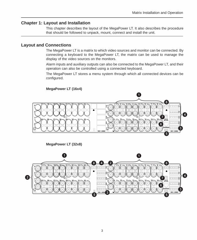
Layout and ConnectionsThe MegaPower LT is a matrix to which video sources and monitor can be connected. Byconnecting a keyboard to the MegaPower LT, the matrix can be used to manage thedisplay of the video sources on the monitors.
Alarm inputs and auxiliary outputs can also be connected to the MegaPower LT, and theiroperation can also be controlled using a connected keyboard.
The MegaPower LT stores a menu system through which all connected devices can beconfigured.
MegaPower LT (16x4)
MegaPower LT (32x8)
4
MegaPower LT
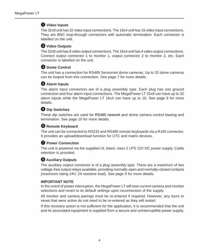
Video InputsThe 32x8 unit has 32 video input connections. The 16x4 unit has 16 video input connections.They are BNC loop-through connectors with automatic termination. Each connector islabelled on the unit.
Video OutputsThe 32x8 unit has 8 video output connections. The 16x4 unit has 4 video output connections.Connect output connector 1 to monitor 1, output connector 2 to monitor 2, etc. Eachconnector is labelled on the unit.
Dome ControlThe unit has a connection for RS485 Sensornet dome cameras. Up to 32 dome camerascan be looped from this connection. See page 7 for more details.
Alarm InputsThe alarm input connectors are of a plug assembly type. Each plug has one groundconnection and four alarm input connections. The MegaPower LT 32x8 can have up to 32alarm inputs while the MegaPower LT 16x4 can have up to 16. See page 9 for moredetails.
Dip SwitchesThese dip switches are used for RS485 network and dome camera control biasing andtermination. See page 10 for more details.
Remote KeyboardThe unit can be connected to RS232 and RS485 remote keyboards via a RJ45 connector.It provides an upload/download function for UTC and matrix devices.
Power ConnectionThe unit is powered via the supplied UL listed, class 2 LPS 12V DC power supply. Cableretention is provided.
Auxiliary OutputsThe auxiliary output connector is of a plug assembly type. There are a maximum of twovoltage-free output relays available, providing normally-open and normally-closed contacts(maximum rating 24V, 2A resistive load). See page 9 for more details.
IMPORTANT NOTEIn the event of power interruption, the MegaPower LT will lose current camera and monitorselections and revert to its default settings upon reconnection of the supply.
All monitor and camera pairings must be re-entered if required. However, any tours orviews that were active do not need to be re-entered as they will restart.
If this recovery action is not sufficient for the application, it is recommended that the unitand its associated equipment is supplied from a secure and uninterruptible power supply.

5
Matrix Installation and Operation
UnpackingThe packaging should contain the following items. Check all product codes on the label.If you have an incorrect item or it is damaged then inform your supplier and the carriersimmediately. If the equipment is incorrect or damaged, do not attempt to use it.
• The MegaPower LT unit
• MP-PSU power supply unit
• UK cable and plug - plug to BS1363 fitted with a 3 Amp standard fuse and IEC C7
• USA cable and plug - UL listed 18 AWG SPT cable with USA NEMA 1-15 P plug andIEC C7
• Standard mainland European cable and plug - UL listed 18 AWG SPT cable with 2pin EUROPLUG EN 50075 2.5 A 250 Volt plug and IEC C7
• 7 foot/2 meters long category 5 connecting cord terminated with RJ45 connectors(MP-CBL)
• Two mounting brackets with screws
• These instructions and a CD holding the manual in other languages
• ADCC0200 keyboard (ADMPLT16C2 and ADMPLT32C2 only)
• ADCC0300 keyboard (ADMPLT16C3 and ADMPLT32C3 only)
Kits are available (ADCCACPSN and ADCCACPSP) when multiple network keyboardsare used. This kit includes:
• MP-KMI Keyboard Matrix Interface
• 7 foot/2 meters long category 5 connecting cord terminated with RJ45 connectors(MP-CBL)
• MP-PSU power supply unit
For multiple network keyboard installations, Belden network cable (Belden 8761 orequivalent single twisted pair, screened, 22 AWG) may be required. This is to be providedby the installer.
Installation GuidelinesInstallation of all CCTV equipment is to be carried out to national or international electricalcodes. For a more detailed reference, refer to:
• United States - National Fire Protection Association (NFPA70), United States NationalElectrical Code.
• Canada - Canadian Electrical Code, part 1, CSA C22.1.
• Other Countries - International Electromechanical Commission (IEC) 60364, Part 1through Part 7.
6
MegaPower LT
Mounting the UnitAll models of the MegaPower LT unit are equipped with mounting holes and are suppliedwith screws and brackets for the optional fitting to a suitable rack or wall. Should the unitbe mounted, particular attention should be paid to ensure that the specification of theequipment is not compromised. In particular, airflow, access, power isolation, weight andany possible contamination should be considered, as should the potential for any abusethat may lead to an operational malfunction or safety violation.
When choosing a suitable location for the unit, ensure:
• An electrical output socket with overload and short circuit protection is located withina suitable distance for the included MP-PSU power supply.
• The power supply cord cannot become pinched or trapped under a heavy object.The power cord should be routed so that it is not likely to be walked on.
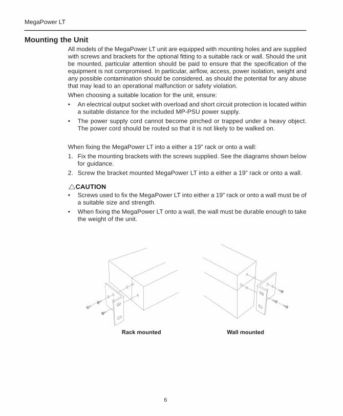
When fixing the MegaPower LT into a either a 19” rack or onto a wall:
1. Fix the mounting brackets with the screws supplied. See the diagrams shown belowfor guidance.
2. Screw the bracket mounted MegaPower LT into a either a 19” rack or onto a wall.
• Screws used to fix the MegaPower LT into either a 19” rack or onto a wall must be ofa suitable size and strength.
• When fixing the MegaPower LT onto a wall, the wall must be durable enough to takethe weight of the unit.
7
Matrix Installation and Operation
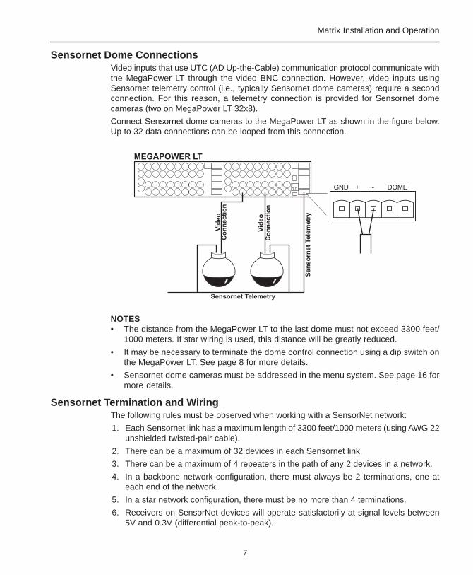
Sensornet Dome ConnectionsVideo inputs that use UTC (AD Up-the-Cable) communication protocol communicate withthe MegaPower LT through the video BNC connection. However, video inputs usingSensornet telemetry control (i.e., typically Sensornet dome cameras) require a secondconnection. For this reason, a telemetry connection is provided for Sensornet domecameras (two on MegaPower LT 32x8).
Connect Sensornet dome cameras to the MegaPower LT as shown in the figure below.Up to 32 data connections can be looped from this connection.
NOTES• The distance from the MegaPower LT to the last dome must not exceed 3300 feet/
1000 meters. If star wiring is used, this distance will be greatly reduced.
• It may be necessary to terminate the dome control connection using a dip switch onthe MegaPower LT. See page 8 for more details.
• Sensornet dome cameras must be addressed in the menu system. See page 16 formore details.
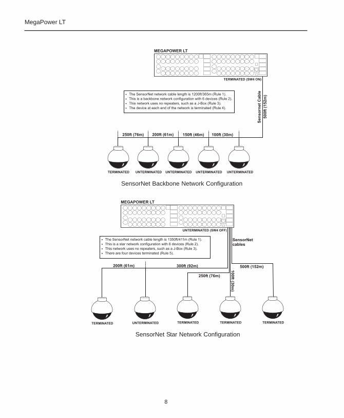
Sensornet Termination and WiringThe following rules must be observed when working with a SensorNet network:
1. Each Sensornet link has a maximum length of 3300 feet/1000 meters (using AWG 22unshielded twisted-pair cable).
2. There can be a maximum of 32 devices in each Sensornet link.
3. There can be a maximum of 4 repeaters in the path of any 2 devices in a network.
4. In a backbone network configuration, there must always be 2 terminations, one ateach end of the network.
5. In a star network configuration, there must be no more than 4 terminations.
6. Receivers on SensorNet devices will operate satisfactorily at signal levels between5V and 0.3V (differential peak-to-peak).
8
MegaPower LT
SensorNet Backbone Network Configuration
SensorNet Star Network Configuration
9
Matrix Installation and Operation
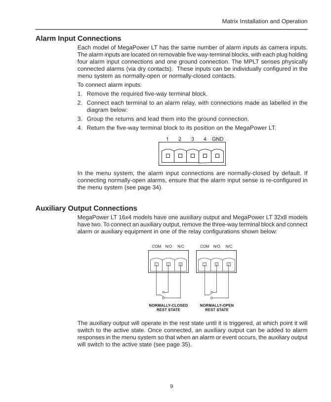
Alarm Input ConnectionsEach model of MegaPower LT has the same number of alarm inputs as camera inputs.The alarm inputs are located on removable five way-terminal blocks, with each plug holdingfour alarm input connections and one ground connection. The MPLT senses physicallyconnected alarms (via dry contacts). These inputs can be individually configured in themenu system as normally-open or normally-closed contacts.
To connect alarm inputs:
1. Remove the required five-way terminal block.
2. Connect each terminal to an alarm relay, with connections made as labelled in thediagram below:
3. Group the returns and lead them into the ground connection.
4. Return the five-way terminal block to its position on the MegaPower LT.
In the menu system, the alarm input connections are normally-closed by default. Ifconnecting normally-open alarms, ensure that the alarm input sense is re-configured inthe menu system (see page 34).
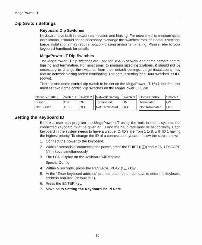
Auxiliary Output ConnectionsMegaPower LT 16x4 models have one auxiliary output and MegaPower LT 32x8 modelshave two. To connect an auxiliary output, remove the three-way terminal block and connectalarm or auxiliary equipment in one of the relay configurations shown below:
The auxiliary output will operate in the rest state until it is triggered, at which point it willswitch to the active state. Once connected, an auxiliary output can be added to alarmresponses in the menu system so that when an alarm or event occurs, the auxiliary outputwill switch to the active state (see page 35).
10
MegaPower LT
Dip Switch Settings
Keyboard Dip SwitchesKeyboard have built in network termination and biasing. For most small to medium sizedinstallations, it should not be necessary to change the switches from their default settings.Large installations may require network biasing and/or terminating. Please refer to yourkeyboard handbook for details.
MegaPower LT Dip SwitchesThe MegaPower LT dip switches are used for RS485 network and dome camera controlbiasing and termination. For most small to medium sized installations, it should not benecessary to change the switches from their default settings. Large installations mayrequire network biasing and/or terminating. The default setting for all four switches is OFF(down).
There is one dome control dip switch to be set on the MegaPower LT 16x4, but the usermust set two dome control dip switches on the MegaPower LT 32x8.
Setting the Keyboard IDBefore a user can program the MegaPower LT using the built-in menu system, theconnected keyboard must be given an ID and the baud rate must be set correctly. Eachkeyboard in the system needs to have a unique ID. ID’s are from 1 to 8, with ID 1 havingthe highest priority. To change the ID of a connected keyboard, follow the steps below:
1. Connect the power to the keyboard.
2. Within 5 seconds of connecting the power, press the SHIFT ( ) and MENU ESCAPE( ) keys simultaneously.
3. The LCD display on the keyboard will display:
Special Config
4. Within 5 seconds, press the REVERSE PLAY ( ) key.
5. At the "Enter keyboard address" prompt, use the number keys to enter the keyboardaddress required (default is 1).
6. Press the ENTER key.
7. Move on to Setting the Keyboard Baud Rate.
Network Setting Switch 1 Switch 2 Network Setting Switch 3 Dome Control Switch 4
Biased ON ON Terminated ON Terminated ON
Not Biased OFF OFF Not Terminated OFF Not Terminated OFF

11
Matrix Installation and Operation
Setting the Keyboard Baud RateThe current keyboard baud rate setting can be seen when the keyboard is powered up.Optimum performance of the MegaPower LT is achieved by setting the keyboard baudrate to 19200. To change the baud rate of a connected keyboard, follow the steps below:
1. Connect the power to the keyboard.
2. Within 5 seconds of reconnecting the power, press the SHIFT ( ) and MENUESCAPE ( ) keys simultaneously.
3. The LCD display on the keyboard should display:
Special Config
4. Within 5 seconds, press the REWIND ( ) key.
5. At the "1=RS485 2=RS232" prompt, select the required mode and then press theENTER key. It should be noted that the default is RS485.
6. The LCD display will show the first baud rate options. Use the 0 key to toggle throughthe available options.
7. Press the number key for the desired baud rate.
NOTEReducing the baud rate from the optimum setting will reduce the number of keyboardsthat can perform telemetry operations at any one time.
12
MegaPower LT
Chapter 2: The Menu SystemThe menu system is used to program the MegaPower LT as required using the keyboard.This chapter give details about how to use the menu system. Menu operation and navigationis documented for RS485 keyboards. RS232 keyboard functionality may differ.
Status LevelsThere are three different user status levels, two of which have access to the menu system.
Operator – only operates the system. No menu access allowed.
Supervisor – is able to modify settings within the Supervisor menu.
Administrator/Installer – has access to all menu items.
Menu NavigationA keyboard joystick can be used to navigate the menu system. In general, a menu item isselected and edited as follows:
1. Use Joystick Up/Down movements to move between menu items. The currentlyselected menu item will flash.
2. Use the ENTER key or Joystick Right to select a menu item.
3. In the resulting screen, use:
• The Joystick Up/Down movement to move through the menu items in a screen.
• The Joystick Left/Right to toggle through and select the options for a menu item.
• The numerical keys to input numerical data.
• The SHIFT ( ) key held down whilst using Joystick Up/Down movements tochange between capital letters and lower-case.
• The MENU ESCAPE ( ) key to return to the previous menu.
NOTES• When menu items are being edited, automatic functions (e.g. alarms and tours)
cease operating.
• Menus can be displayed on any monitor, however only one monitor can display themenus at once.
• Any operation calling for the use of the SHIFT ( ) key requires this key to be helddown whilst another key is pressed. This is the same way in which the SHIFT keyoperates on a PC keyboard.
• When making changes in a screen, use the Joystick Down command to scroll throughthe fields, completing each one in turn. Scrolling back up the screen after changeshave been made will cause the changes to be lost.
13
Matrix Installation and Operation
Pin Validation
Enter Pin _ _ _ _
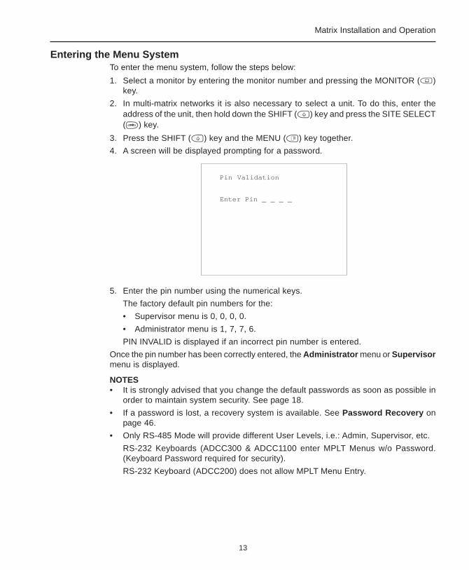
Entering the Menu SystemTo enter the menu system, follow the steps below:
1. Select a monitor by entering the monitor number and pressing the MONITOR ( )key.
2. In multi-matrix networks it is also necessary to select a unit. To do this, enter theaddress of the unit, then hold down the SHIFT ( ) key and press the SITE SELECT( ) key.
3. Press the SHIFT ( ) key and the MENU ( ) key together.
4. A screen will be displayed prompting for a password.
5. Enter the pin number using the numerical keys.
The factory default pin numbers for the:
• Supervisor menu is 0, 0, 0, 0.
• Administrator menu is 1, 7, 7, 6.
PIN INVALID is displayed if an incorrect pin number is entered.
Once the pin number has been correctly entered, the Administrator menu or Supervisormenu is displayed.
NOTES• It is strongly advised that you change the default passwords as soon as possible in
order to maintain system security. See page 18.
• If a password is lost, a recovery system is available. See Password Recovery onpage 46.
• Only RS-485 Mode will provide different User Levels, i.e.: Admin, Supervisor, etc.
RS-232 Keyboards (ADCC300 & ADCC1100 enter MPLT Menus w/o Password.(Keyboard Password required for security).
RS-232 Keyboard (ADCC200) does not allow MPLT Menu Entry.

14
MegaPower LT
Saving and ExitingIt is important to know how to save changes in the menu system before they are made.
To save changes to the menu system, follow the steps below:
1. Select the Return to option at the bottom of each screen until the Administratormenu or Supervisor menu is displayed.
2. Select the Exit Menu option at the bottom of the screen to enter the Exit menu (seefigure above).
3. Either:
• Select Save and exit to save changes made and then exit the menu system.
• Select Exit without saving to exit the menu system without saving the changesmade.
If the menus are left idle for 180 seconds or over the menu will time out without saving.
Administrator and Supervisor MenusUsers with Administrator status level have access to alarm and installation features aswell as all the functions available to the Supervisor.
Exit Menu
Save and exitExit without saving
Return to Menus
Administrator Menu
1 Time/Date Menu2 Camera Menu3 System Menu4 View Menu5 Alarm Menu6 Installer Menu
Exit Menu
Supervisor Menu
1 Time/Date Menu2 Camera Menu3 System Menu4 View menu
Exit Menu
15
Matrix Installation and Operation
1 Time/Date Menu
1.1 Time format :12H1.2 Date format :mmddyy1.3 Set time :12:00:001.4 Set date :21:06:021.5 DST :FORWARD
Apply new time and date
Return to Menu
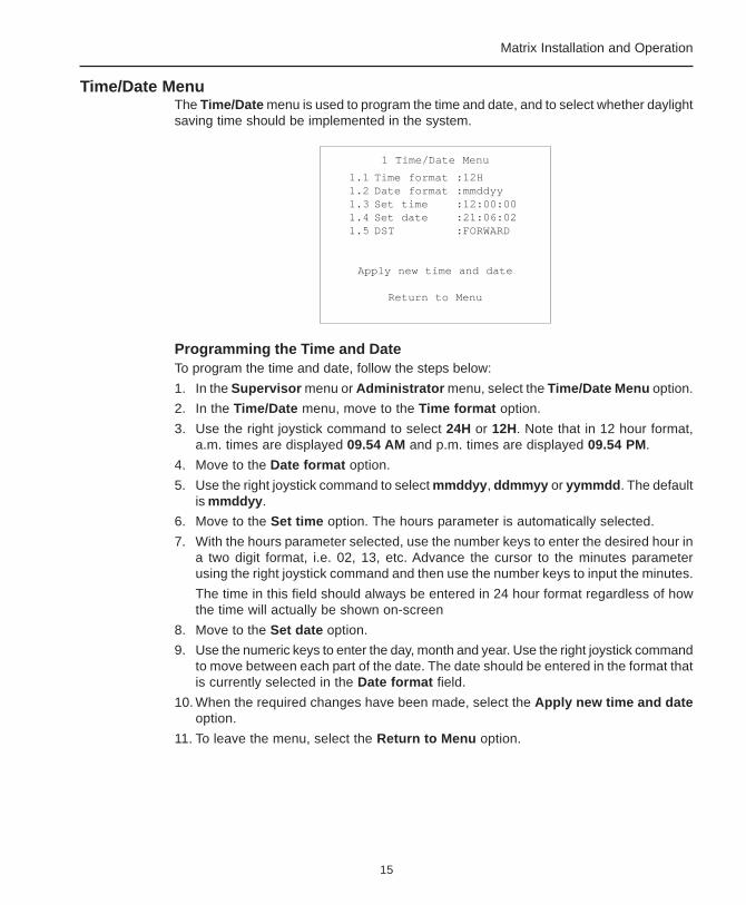
Time/Date MenuThe Time/Date menu is used to program the time and date, and to select whether daylightsaving time should be implemented in the system.
Programming the Time and DateTo program the time and date, follow the steps below:
1. In the Supervisor menu or Administrator menu, select the Time/Date Menu option.
2. In the Time/Date menu, move to the Time format option.
3. Use the right joystick command to select 24H or 12H. Note that in 12 hour format,a.m. times are displayed 09.54 AM and p.m. times are displayed 09.54 PM.
4. Move to the Date format option.
5. Use the right joystick command to select mmddyy, ddmmyy or yymmdd. The defaultis mmddyy.
6. Move to the Set time option. The hours parameter is automatically selected.
7. With the hours parameter selected, use the number keys to enter the desired hour ina two digit format, i.e. 02, 13, etc. Advance the cursor to the minutes parameterusing the right joystick command and then use the number keys to input the minutes.
The time in this field should always be entered in 24 hour format regardless of howthe time will actually be shown on-screen
8. Move to the Set date option.
9. Use the numeric keys to enter the day, month and year. Use the right joystick commandto move between each part of the date. The date should be entered in the format thatis currently selected in the Date format field.
10. When the required changes have been made, select the Apply new time and dateoption.
11. To leave the menu, select the Return to Menu option.
16
MegaPower LT
DST (Daylight Saving Time)The DST menu item is used to select BACK or FORWARD on the day prior to the timechange. The system will then put the clock back or forward by an hour the next time thetime reaches 2 a.m. After the time change has been made, the DST option thenautomatically resets to NONE.
NOTEThe unit has a battery-backed clock that retains the correct time, date and all otherprogrammed data in the event of a loss of power.
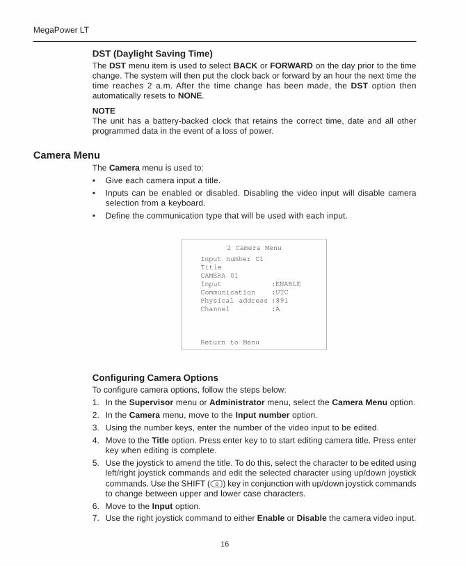
Camera MenuThe Camera menu is used to:
• Give each camera input a title.
• Inputs can be enabled or disabled. Disabling the video input will disable cameraselection from a keyboard.
• Define the communication type that will be used with each input.
Configuring Camera OptionsTo configure camera options, follow the steps below:
1. In the Supervisor menu or Administrator menu, select the Camera Menu option.
2. In the Camera menu, move to the Input number option.
3. Using the number keys, enter the number of the video input to be edited.
4. Move to the Title option. Press enter key to to start editing camera title. Press enterkey when editing is complete.
5. Use the joystick to amend the title. To do this, select the character to be edited usingleft/right joystick commands and edit the selected character using up/down joystickcommands. Use the SHIFT ( ) key in conjunction with up/down joystick commandsto change between upper and lower case characters.
6. Move to the Input option.7. Use the right joystick command to either Enable or Disable the camera video input.
2 Camera Menu
Input number C1TitleCAMERA 01Input :ENABLECommunication :UTCPhysical address :891Channel :A
Return to Menu
17
Matrix Installation and Operation
8. Move to the Communication option.9. Use the right joystick command to select either OFF, UTC, SNET or SNET-V (for
SDU7 and above). Select UTC when AD Up-the-Cable (UTC) protocol is to be usedto communicate with the camera input or select SNET where Sensornet telemetrycontrol is to be used. Select OFF if the input does not use either of thesecommunication protocols.
10. If the Communication option is set to SNET, it is necessary to set an address for thevideo input in the Physical Address field. The address that is entered must matchthe input's local address (e.g., the address set inside the dome camera). It does notneed to match the video input number.If the Communication option is set to UTC, the Physical address field will be disabledand the address is automatically set to 891. Note that if a connected dome camerais using UTC communication, the dome camera address must be set locally to 891.
11. The Channel option is only enabled when the Communication option is set to SNET.This field should be set to A for MPLT 16 or A and B for MPLT 32. Verify that thedome data connection is made to the correct port on the rear of the MPLT.
12. Once amendments are complete, select the Return to Menu option.
NOTES• Video loss can only be reported on the selected camera.
• The feature will disable automatically if the video signal is changed.
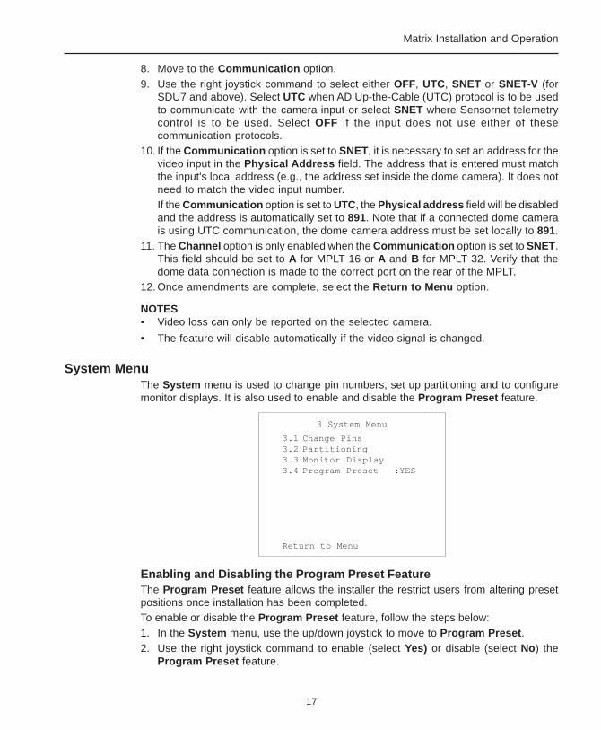
System MenuThe System menu is used to change pin numbers, set up partitioning and to configuremonitor displays. It is also used to enable and disable the Program Preset feature.
Enabling and Disabling the Program Preset FeatureThe Program Preset feature allows the installer the restrict users from altering presetpositions once installation has been completed.To enable or disable the Program Preset feature, follow the steps below:1. In the System menu, use the up/down joystick to move to Program Preset.2. Use the right joystick command to enable (select Yes) or disable (select No) the
Program Preset feature.
3 System Menu
3.1 Change Pins3.2 Partitioning3.3 Monitor Display3.4 Program Preset :YES
Return to Menu

18
MegaPower LT
Changing Pin NumbersThe Change Pins screen is used to change administrator and supervisor pin numbers.
To change a pin number, follow the steps below:
1. In the System menu, select the Change Pins option.
2. In the Change Pins screen, select either the Change Supervisor or ChangeAdministr option depending on which pin number is to be changed. The relevantscreen is displayed.
3. In the Current Pin field, enter the pin number that is currently used to gain access tothe menu system. The cursor automatically moves to the New Pin field.
4. Enter the new four-digit pin number. The cursor automatically moves to theVerification field.
5. Re-enter the new pin number.
At this point, if all fields have been completed correctly, the pin number will be changed.If an incorrect pin number has been entered at any point during the procedure (e.g.,either the current pin number has been entered incorrectly or the entries in the NewPin and Verification fields do not match), or if the user does not have the necessaryaccess privileges, an error message is displayed. At this point, the user will have topress the ENTER key to return to the Change Pins screen.
NOTES• It is strongly advised that the factory set default pin numbers are changed as soon
as possible in order to maintain system security. The default Installer pin number is1776. The default Supervisor pin number is 0000.
• The Administrator can change both the Administrator pin number and the Supervisorpin number. The Supervisor can only change the supervisor pin number.
• If a password is lost, a recovery system is available. See Password Recovery onpage 40.
3.1 Change Pins
3.1.1 Change Supervisor3.1.2 Change Administr
Return to System Menu
3.1.1 Change Supervisor
Current Pin ****New Pin ****
Verification ****
19
Matrix Installation and Operation
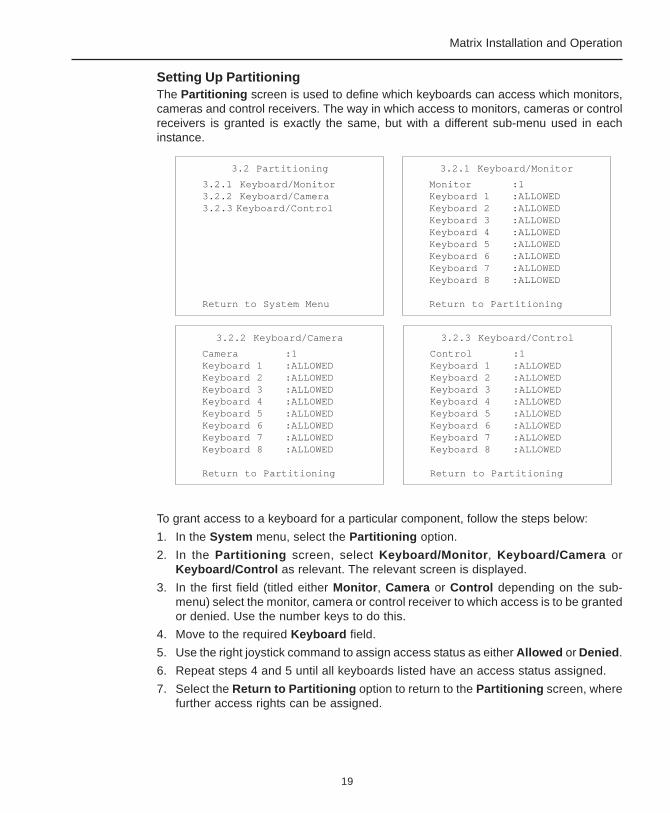
Setting Up PartitioningThe Partitioning screen is used to define which keyboards can access which monitors,cameras and control receivers. The way in which access to monitors, cameras or controlreceivers is granted is exactly the same, but with a different sub-menu used in eachinstance.
To grant access to a keyboard for a particular component, follow the steps below:
1. In the System menu, select the Partitioning option.
2. In the Partitioning screen, select Keyboard/Monitor, Keyboard/Camera orKeyboard/Control as relevant. The relevant screen is displayed.
3. In the first field (titled either Monitor, Camera or Control depending on the sub-menu) select the monitor, camera or control receiver to which access is to be grantedor denied. Use the number keys to do this.
4. Move to the required Keyboard field.
5. Use the right joystick command to assign access status as either Allowed or Denied.
6. Repeat steps 4 and 5 until all keyboards listed have an access status assigned.
7. Select the Return to Partitioning option to return to the Partitioning screen, wherefurther access rights can be assigned.
3.2 Partitioning
3.2.1 Keyboard/Monitor3.2.2 Keyboard/Camera3.2.3 Keyboard/Control
Return to System Menu
3.2.1 Keyboard/Monitor
Monitor :1Keyboard 1 :ALLOWEDKeyboard 2 :ALLOWEDKeyboard 3 :ALLOWEDKeyboard 4 :ALLOWEDKeyboard 5 :ALLOWEDKeyboard 6 :ALLOWEDKeyboard 7 :ALLOWEDKeyboard 8 :ALLOWED
Return to Partitioning
3.2.3 Keyboard/Control
Control :1Keyboard 1 :ALLOWEDKeyboard 2 :ALLOWEDKeyboard 3 :ALLOWEDKeyboard 4 :ALLOWEDKeyboard 5 :ALLOWEDKeyboard 6 :ALLOWEDKeyboard 7 :ALLOWEDKeyboard 8 :ALLOWED
Return to Partitioning
3.2.2 Keyboard/Camera
Camera :1Keyboard 1 :ALLOWEDKeyboard 2 :ALLOWEDKeyboard 3 :ALLOWEDKeyboard 4 :ALLOWEDKeyboard 5 :ALLOWEDKeyboard 6 :ALLOWEDKeyboard 7 :ALLOWEDKeyboard 8 :ALLOWED
Return to Partitioning
20
MegaPower LT
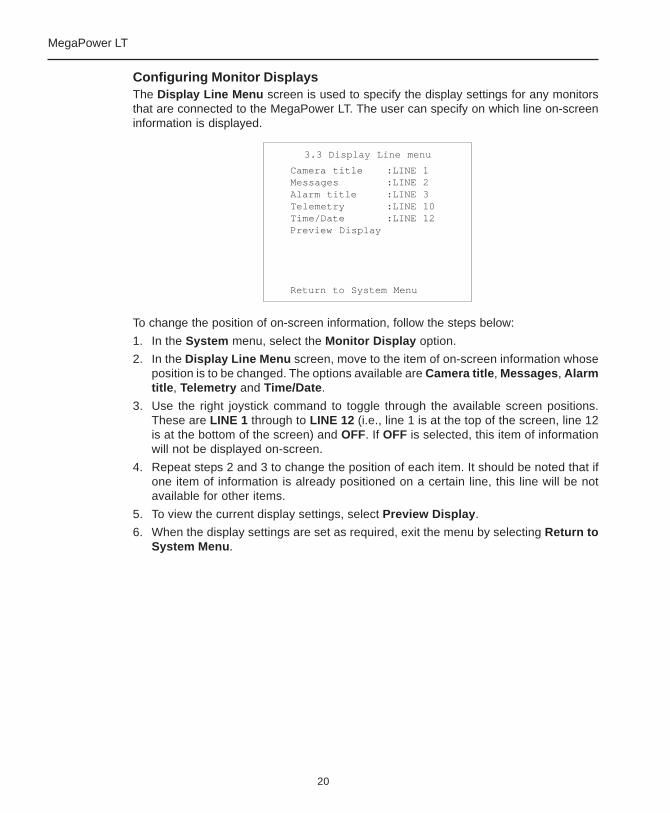
Configuring Monitor DisplaysThe Display Line Menu screen is used to specify the display settings for any monitorsthat are connected to the MegaPower LT. The user can specify on which line on-screeninformation is displayed.
To change the position of on-screen information, follow the steps below:
1. In the System menu, select the Monitor Display option.
2. In the Display Line Menu screen, move to the item of on-screen information whoseposition is to be changed. The options available are Camera title, Messages, Alarmtitle, Telemetry and Time/Date.
3. Use the right joystick command to toggle through the available screen positions.These are LINE 1 through to LINE 12 (i.e., line 1 is at the top of the screen, line 12is at the bottom of the screen) and OFF. If OFF is selected, this item of informationwill not be displayed on-screen.
4. Repeat steps 2 and 3 to change the position of each item. It should be noted that ifone item of information is already positioned on a certain line, this line will be notavailable for other items.
5. To view the current display settings, select Preview Display.
6. When the display settings are set as required, exit the menu by selecting Return toSystem Menu.
3.3 Display Line menu
Camera title :LINE 1Messages :LINE 2Alarm title :LINE 3Telemetry :LINE 10Time/Date :LINE 12Preview Display
Return to System Menu
21
Matrix Installation and Operation
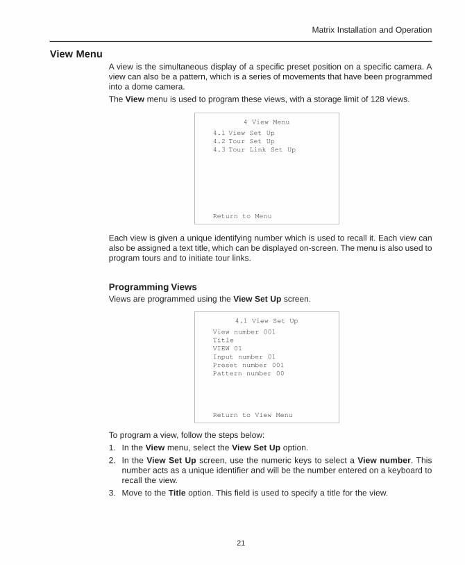
View MenuA view is the simultaneous display of a specific preset position on a specific camera. Aview can also be a pattern, which is a series of movements that have been programmedinto a dome camera.
The View menu is used to program these views, with a storage limit of 128 views.
Each view is given a unique identifying number which is used to recall it. Each view canalso be assigned a text title, which can be displayed on-screen. The menu is also used toprogram tours and to initiate tour links.
Programming ViewsViews are programmed using the View Set Up screen.
To program a view, follow the steps below:
1. In the View menu, select the View Set Up option.
2. In the View Set Up screen, use the numeric keys to select a View number. Thisnumber acts as a unique identifier and will be the number entered on a keyboard torecall the view.
3. Move to the Title option. This field is used to specify a title for the view.
4 View Menu
4.1 View Set Up4.2 Tour Set Up4.3 Tour Link Set Up
Return to Menu
4.1 View Set Up
View number 001TitleVIEW 01Input number 01Preset number 001Pattern number 00
Return to View Menu
22
MegaPower LT
4. Use the joystick to amend the title. To do this, select the character to be edited usingleft/right joystick commands and edit the selected character using up/down joystickcommands. Use the SHIFT ( ) key in conjunction with up/down joystick commandsto change between upper and lower case characters.
5. Move to the Input number option.
6. Using the numeric keys, select the video source that is to be used.
7. Move to the Preset number option. This option is used when the video source is aPTZ camera or dome camera that has been programmed with preset positions.
8. Use the numeric keys to enter the number of the required preset position.
9. If required, move to the Pattern number option. This item is used when the videosource is a dome camera that has been programmed with patterns.
10. If a pattern is to be used, use the numeric keys to enter the number for the requireddome pattern. If a pattern is assigned to a view, the Preset number field automaticallyreverts to a the preset number 0.
11. Once amendments are complete, select the Return to View Menu option.
Using a Keyboard to Recall ViewsOnce views have been programmed to the MegaPower LT, they can be recalled using aconnected keyboard. To do this, follow the steps below:
1. Using the numeric keys, enter the required view number.
2. Press the MULTISCREEN ( ) key.
23
Matrix Installation and Operation
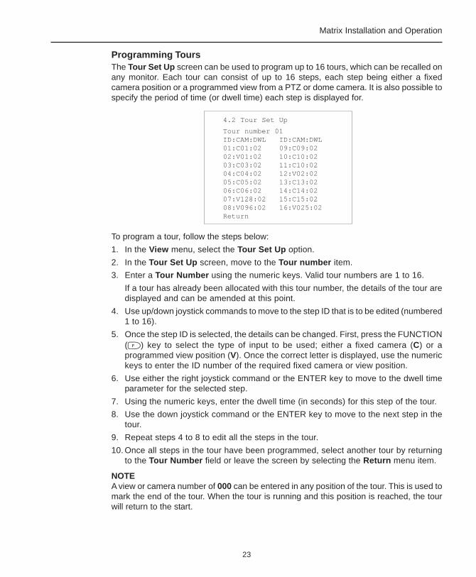
Programming ToursThe Tour Set Up screen can be used to program up to 16 tours, which can be recalled onany monitor. Each tour can consist of up to 16 steps, each step being either a fixedcamera position or a programmed view from a PTZ or dome camera. It is also possible tospecify the period of time (or dwell time) each step is displayed for.
To program a tour, follow the steps below:
1. In the View menu, select the Tour Set Up option.
2. In the Tour Set Up screen, move to the Tour number item.
3. Enter a Tour Number using the numeric keys. Valid tour numbers are 1 to 16.
If a tour has already been allocated with this tour number, the details of the tour aredisplayed and can be amended at this point.
4. Use up/down joystick commands to move to the step ID that is to be edited (numbered1 to 16).
5. Once the step ID is selected, the details can be changed. First, press the FUNCTION( ) key to select the type of input to be used; either a fixed camera (C) or aprogrammed view position (V). Once the correct letter is displayed, use the numerickeys to enter the ID number of the required fixed camera or view position.
6. Use either the right joystick command or the ENTER key to move to the dwell timeparameter for the selected step.
7. Using the numeric keys, enter the dwell time (in seconds) for this step of the tour.
8. Use the down joystick command or the ENTER key to move to the next step in thetour.
9. Repeat steps 4 to 8 to edit all the steps in the tour.
10. Once all steps in the tour have been programmed, select another tour by returningto the Tour Number field or leave the screen by selecting the Return menu item.
NOTEA view or camera number of 000 can be entered in any position of the tour. This is used tomark the end of the tour. When the tour is running and this position is reached, the tourwill return to the start.
4.2 Tour Set Up
Tour number 01ID:CAM:DWL ID:CAM:DWL01:C01:02 09:C09:0202:V01:02 10:C10:0203:C03:02 11:C10:0204:C04:02 12:V02:0205:C05:02 13:C13:0206:C06:02 14:C14:0207:V128:02 15:C15:0208:V096:02 16:V025:02Return

24
MegaPower LT
Linking Tours TogetherThe Tour Link Set Up screen is used to link two tours together to make a single tour withup to 32 positions. Up to eight tour links can be made.
To create a tour link, follow the steps below:
1. In the View menu, select the Tour Link Set Up option.
2. In the Tour Link Set Up screen, use the down joystick command to select one of theeight tour link numbers.
3. Using the numeric keys, enter the number of the first tour to be displayed.
4. Use the right joystick command or the ENTER key to move to the right half of thefield.
5. Using the numeric keys again, enter the number of the second tour to be linked tothe end of the first tour.
6. Use the right joystick or the ENTER key to move to the next tour link number.
7. Repeat steps 2 to 6 to create any further tour links.
8. Once amendments on this screen are complete, select the Return to View Menuoption.
Using a Keyboard to Recall ToursOnce tours have been programmed to the MegaPower LT, they can be recalled using aconnected keyboard. To do this, follow the steps below:
1. Using the numeric keys, enter the number of the tour to be recalled.
2. Press the SEQUENCE ( ) key.
4.3 Tour Link Set Up
1: 01 - 022: 00 - 003: 00 - 004: 00 - 005: 00 - 006: 00 - 007: 00 - 008: 00 - 00
Return to View Menu
25
Matrix Installation and Operation
Cancelling a TourA tour is cancelled when:
• A camera is called to display on the monitor.
• A telemetry command for the monitor is issued.
• An alarm is triggered. The tour is re-enabled automatically when the alarm is cleared.
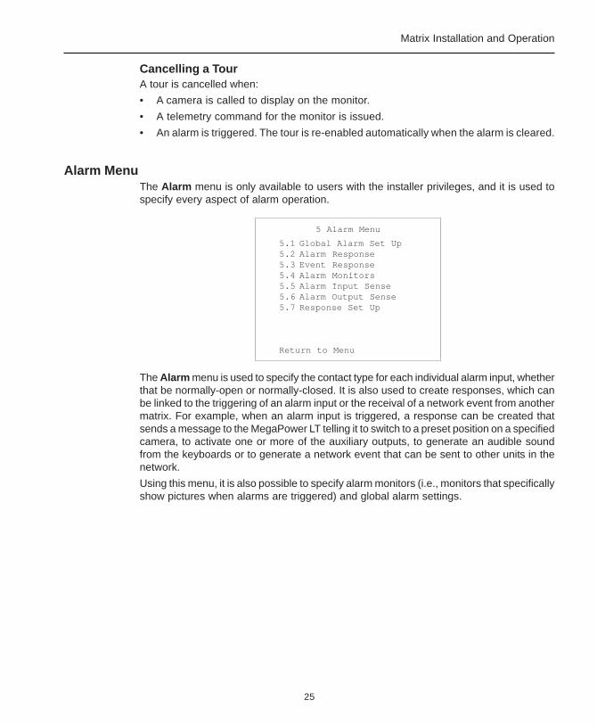
Alarm MenuThe Alarm menu is only available to users with the installer privileges, and it is used tospecify every aspect of alarm operation.
The Alarm menu is used to specify the contact type for each individual alarm input, whetherthat be normally-open or normally-closed. It is also used to create responses, which canbe linked to the triggering of an alarm input or the receival of a network event from anothermatrix. For example, when an alarm input is triggered, a response can be created thatsends a message to the MegaPower LT telling it to switch to a preset position on a specifiedcamera, to activate one or more of the auxiliary outputs, to generate an audible soundfrom the keyboards or to generate a network event that can be sent to other units in thenetwork.
Using this menu, it is also possible to specify alarm monitors (i.e., monitors that specificallyshow pictures when alarms are triggered) and global alarm settings.
NOTEA system keyboard can be used to manually generate an alarm. To do this, press theFUNCTION ( ) key, enter the number of the alarm input to be triggered and then pressthe ALARM ACKNOWLEDGE ( ) key.
5 Alarm Menu
5.1 Global Alarm Set Up5.2 Alarm Response5.3 Event Response5.4 Alarm Monitors5.5 Alarm Input Sense5.6 Alarm Output Sense5.7 Response Set Up
Return to Menu
26
MegaPower LT
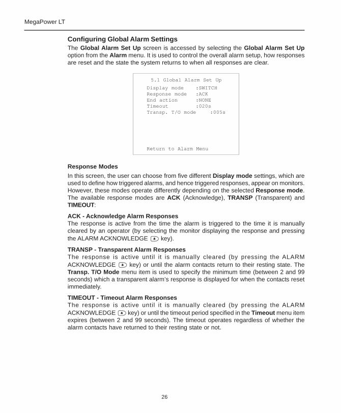
Configuring Global Alarm SettingsThe Global Alarm Set Up screen is accessed by selecting the Global Alarm Set Upoption from the Alarm menu. It is used to control the overall alarm setup, how responsesare reset and the state the system returns to when all responses are clear.
Response Modes
In this screen, the user can choose from five different Display mode settings, which areused to define how triggered alarms, and hence triggered responses, appear on monitors.However, these modes operate differently depending on the selected Response mode.The available response modes are ACK (Acknowledge), TRANSP (Transparent) andTIMEOUT:
ACK - Acknowledge Alarm ResponsesThe response is active from the time the alarm is triggered to the time it is manuallycleared by an operator (by selecting the monitor displaying the response and pressingthe ALARM ACKNOWLEDGE key).
TRANSP - Transparent Alarm ResponsesThe response is active until it is manually cleared (by pressing the ALARMACKNOWLEDGE key) or until the alarm contacts return to their resting state. TheTransp. T/O Mode menu item is used to specify the minimum time (between 2 and 99seconds) which a transparent alarm’s response is displayed for when the contacts resetimmediately.
TIMEOUT - Timeout Alarm ResponsesThe response is active until it is manually cleared (by pressing the ALARMACKNOWLEDGE key) or until the timeout period specified in the Timeout menu itemexpires (between 2 and 99 seconds). The timeout operates regardless of whether thealarm contacts have returned to their resting state or not.
5.1 Global Alarm Set Up
Display mode :SWITCHResponse mode :ACKEnd action :NONETimeout :020sTransp. T/O mode :005s
Return to Alarm Menu
27
Matrix Installation and Operation
Display Modes
The five display modes operate differently depending on the response mode that hasbeen selected. The available display modes are:
NONENo change to the monitor display is made when an response is triggered.
LAST - Last In First OutIn this display mode, each response is displayed on all alarm monitors (according to thesettings made in the Alarm Monitor screen, see overleaf). The next response to betriggered replaces the current one (on all the monitors), although in Transparent orTimeout response mode, the respective timeout periods must have passed first. Thisminimum timeout is intended to ensure that no triggered responses disappear immediatelywithout being observed.
In Acknowledge response mode, previously triggered responses disappear when a newone arrives. This can lead to a response not being carried out. The currently displayedresponse is cancelled regardless of whether the alarm contacts are still active.
STACKAs each triggered response arrives it is shown on the next available alarm monitor(according to the settings made in the Alarm Monitor screen, see overleaf). Once all thealarm monitors are full, the next response is placed in a queue. When a response iscleared it is replaced by the next one in the queue.
SWITCHThe first triggered response is shown on all the alarm monitors. Once it is cleared, thenext response is displayed on all alarm monitors.
ROTATEOnly to be used in Acknowledge response mode. This option switches the triggeredresponse to all available alarm monitors. If multiple responses are triggered, each responseis displayed in a cycling sequence. In each cycle, each response is displayed for thelength of time defined in the Transp. T/O mode menu item. In addition, auxiliary outputsare disabled.
End Action
The Global Alarm Set Up screen also has a menu item titled End action. This option isused to set what the system does once all alarms (and therefore responses) have beencleared. This can be set to RETURN or NONE. RETURN will return the monitors to theirpre-alarm states when all alarms are cleared. NONE will leave the monitors in their alarmstate. This will also switch off any tours running prior to the alarm condition.
28
MegaPower LT
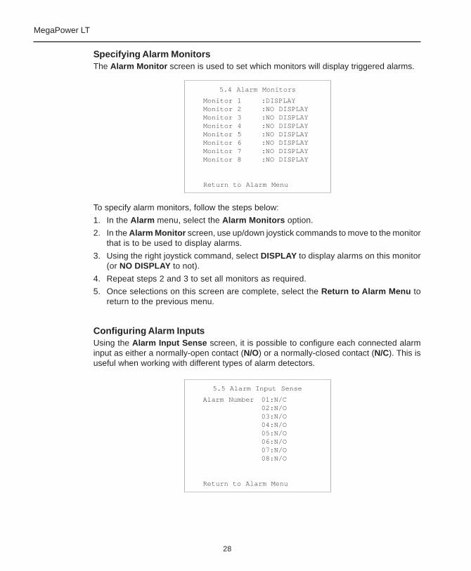
Specifying Alarm MonitorsThe Alarm Monitor screen is used to set which monitors will display triggered alarms.
To specify alarm monitors, follow the steps below:
1. In the Alarm menu, select the Alarm Monitors option.
2. In the Alarm Monitor screen, use up/down joystick commands to move to the monitorthat is to be used to display alarms.
3. Using the right joystick command, select DISPLAY to display alarms on this monitor(or NO DISPLAY to not).
4. Repeat steps 2 and 3 to set all monitors as required.
5. Once selections on this screen are complete, select the Return to Alarm Menu toreturn to the previous menu.
Configuring Alarm InputsUsing the Alarm Input Sense screen, it is possible to configure each connected alarminput as either a normally-open contact (N/O) or a normally-closed contact (N/C). This isuseful when working with different types of alarm detectors.
5.4 Alarm Monitors
Monitor 1 :DISPLAYMonitor 2 :NO DISPLAYMonitor 3 :NO DISPLAYMonitor 4 :NO DISPLAYMonitor 5 :NO DISPLAYMonitor 6 :NO DISPLAYMonitor 7 :NO DISPLAYMonitor 8 :NO DISPLAY
Return to Alarm Menu
5.5 Alarm Input Sense
Alarm Number 01:N/C02:N/O03:N/O04:N/O05:N/O06:N/O07:N/O08:N/O
Return to Alarm Menu

29
Matrix Installation and Operation
To configure alarm inputs, follow the steps below:
1. In the Alarm menu, select the Alarm Input Sense option.
2. In the Alarm Input Sense screen, use the numeric keys to enter the number of thealarm input to be configured and press the ENTER key to jump to it. The up/downjoystick commands can also be used to move through the inputs.
3. Using the right joystick command, select N/O to configure the alarm input as anormally-open contact or select N/C to configure it as a normally-closed contact.
4. Repeat steps 2 and 3 to set all alarm inputs as required.
5. Once selections on this screen are complete, select the Return to Alarm Menu toreturn to the previous menu.
Configuring Auxiliary OutputsAuxiliary outputs can be connected to the MegaPower LT in a normally-open or a normally-closed rest state. An auxiliary output will operate in a rest state until it is triggered, atwhich point it will switch to the active state.
Once connected, an auxiliary output can be added to alarm responses so that when analarm or event occurs, the auxiliary output will switch to the active state (see page 36).
The Alarm Output Sense menu is reserved for future use. Currently, changing the settingsin this menu will have no effect on the operation of the MegaPower LT.
30
MegaPower LT
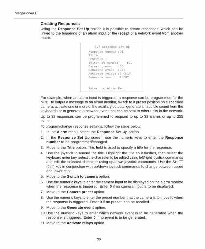
Creating ResponsesUsing the Response Set Up screen it is possible to create responses, which can belinked to the triggering of an alarm input or the receipt of a network event from anothermatrix.
For example, when an alarm input is triggered, a response can be programmed for theMPLT to output a message to an alram monitor, switch to a preset position on a specifiedcamera, activate one or more of the auxiliary outputs, generate an audible sound from thekeyboards or to generate a network event that can be sent to other units in the network.
Up to 32 responses can be programmed to respond to up to 32 alarms or up to 255events.
To program/change response settings, follow the steps below:
1. In the Alarm menu, select the Response Set Up option.
2. In the Response Set Up screen, use the numeric keys to enter the Responsenumber to be programmed/changed.
3. Move to the Title option. This field is used to specify a title for the response.
4. Use the joystick to amend the title. Highlight the title so it flashes, then select thekeyboard enter key, select the character to be edited using left/right joystick commandsand edit the selected character using up/down joystick commands. Use the SHIFT( ) key in conjunction with up/down joystick commands to change between upperand lower case.
5. Move to the Switch to camera option.
6. Use the numeric keys to enter the camera input to be displayed on the alarm monitorwhen the response is triggered. Enter 0 if no camera input is to be displayed.
7. Move to the Camera preset option.
8. Use the numeric keys to enter the preset number that the camera is to move to whenthe response is triggered. Enter 0 if no preset is to be recalled.
9. Move to the Generate event option.
10. Use the numeric keys to enter which network event is to be generated when theresponse is triggered. Enter 0 if no event is to be generated.
11. Move to the Activate relays option.
5.7 Response Set Up
Response number :01Title :RESPONSE 1Switch to camera :01Camera preset :00Generate event :255Activate relays :1 ONLYGenerate sound :SHORT
Return to Alarm Menu
31
Matrix Installation and Operation
12. Specify whether either of the auxiliary outputs should be activated when the responseis triggered. The options available are 1 ONLY, 2 ONLY, 1 AND 2 or NONE (MPLT 32only); 1 ONLY (MPLT 16).
13. Move to the Generate sound option.
14. Select the urgency of the keyboard beep which will sound on all connected keyboardswhen the response is triggered. The options are NONE, SHORT, MEDIUM and LONG.
15. Once all selections have been made, repeat steps 2 to 14 to program furtherresponses or select Return to Alarm Menu to return to the previous menu.
NOTEOn exiting the Response Set Up screen, the MegaPower LT checks to ensure that aresponse loop has not been created in the menu, which could lock the matrix into permanentalarm status. If a loop is found (for example, response number 3 has been programmedto generate network event number 55, which has been programmed to trigger response3 in the Event Responses screen), a warning message is displayed and the user mustreturn to the Response Set Up screen to remove the loop.
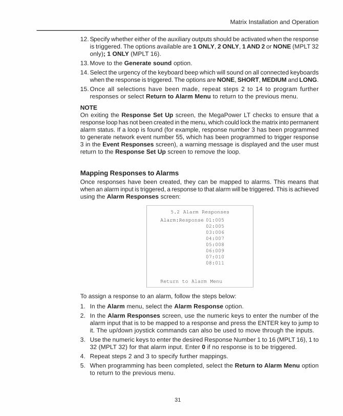
Mapping Responses to AlarmsOnce responses have been created, they can be mapped to alarms. This means thatwhen an alarm input is triggered, a response to that alarm will be triggered. This is achievedusing the Alarm Responses screen:
To assign a response to an alarm, follow the steps below:
1. In the Alarm menu, select the Alarm Response option.
2. In the Alarm Responses screen, use the numeric keys to enter the number of thealarm input that is to be mapped to a response and press the ENTER key to jump toit. The up/down joystick commands can also be used to move through the inputs.
3. Use the numeric keys to enter the desired Response Number 1 to 16 (MPLT 16), 1 to32 (MPLT 32) for that alarm input. Enter 0 if no response is to be triggered.
4. Repeat steps 2 and 3 to specify further mappings.
5. When programming has been completed, select the Return to Alarm Menu optionto return to the previous menu.
5.2 Alarm Responses
Alarm:Response 01:00502:00503:00604:00705:00806:00907:01008:011
Return to Alarm Menu

32
MegaPower LT
Mapping Responses to EventsAn event is a message that can be sent from an MPLT either as a broadcast message oran alarm. A response to the event can be activated by any MPLT on the RS485 network.
Once responses have been created, they can also be mapped to events. This means thatwhen an event is received from another matrix, a response to that event will be triggered.This is achieved using the Event Response screen:
To assign a response to an event, follow the steps below:
1. In the Alarm menu, select the Event Response option.
2. In the Event Responses screen, use the numeric keys to enter the number of theevent that is to be mapped to a response and press the ENTER key to jump to it. Theup/down joystick commands can also be used to move through the events.
3. Use the numeric keys to enter the desired Response Number (1 to 32) for that event.Enter 0 if no response is to be triggered.
4. Repeat steps 2 and 3 to specify further mappings.
5. When programming has been completed, select the Return to Alarm Menu optionto return to the previous menu.
5.3 Event Responses
Event:Response 01:00502:00503:00604:00705:00806:00907:01008:011
Return to Alarm Menu

33
Matrix Installation and Operation
Programming an Alarm: A SummaryThe process of programming an alarm can be quite complicated due to the number ofmenu screens that need to be used. It is also important to note that there are globalsettings which affect the operation of ALL alarms (e.g., global alarms set up, alarm monitors)and individual settings, where alarms are configured one by one.
To program alarms, follow the steps below:
1. Configure the global alarm settings. To do this, select the Global Alarm Set Upoption from the Alarm menu. The Global Alarm Set Up screen is displayed (page26), in which the user can specify response and display modes for all alarms.
2. From the Alarm menu, select the Alarm Monitors option. In the Alarm Monitorsscreen (page 28), specify which system monitors will display alarms and which willnot.
3. Return to the Alarm menu and select the Alarm Input Sense option. In the AlarmInput Sense screen (page 28), configure each individual alarm input as normally-open or normally-closed.
4. Return to the Alarm menu once more and select the Response Set Up menu option.In the Response Set Up screen (page 30), create alarm responses that can betriggered when alarm inputs are activated. Each response can consist of an alarmcamera and preset, specifies whether auxiliary outputs should be triggered andwhether sounds or network events should be generated.
5. Once any required alarm responses have been created, it is necessary to link alarminputs and responses to each other. To do this, select the Alarm Response optionfrom the Alarm menu. In the Alarm Responses screen (page 31), specify whichindividual response will be triggered when each individual alarm input is activated.
If the user has programmed response 1 for alarm input 1, response 2 for alarm input2, etc, there is no need to change the settings in this menu.
6. It is also possible to specify that responses should be triggered by network eventsfrom other matrices. To do this, select the Event Response option from the Alarmmenu. In the Event Responses screen (page 38), specify which individual responsewill be triggered when each individual event is received by the MegaPower LT.
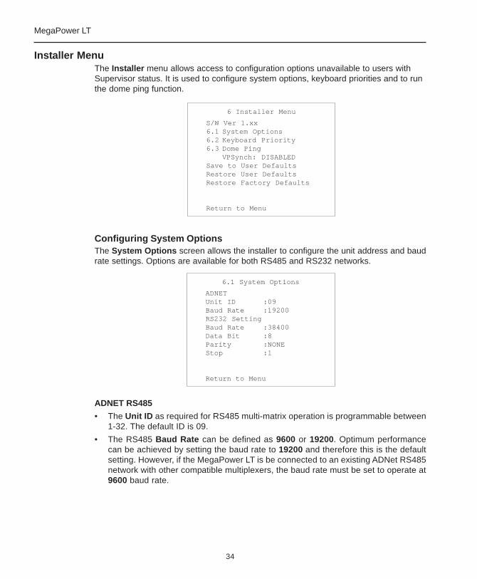
34
MegaPower LT
Installer MenuThe Installer menu allows access to configuration options unavailable to users withSupervisor status. It is used to configure system options, keyboard priorities and to runthe dome ping function.
Configuring System OptionsThe System Options screen allows the installer to configure the unit address and baudrate settings. Options are available for both RS485 and RS232 networks.
ADNET RS485
• The Unit ID as required for RS485 multi-matrix operation is programmable between1-32. The default ID is 09.
• The RS485 Baud Rate can be defined as 9600 or 19200. Optimum performancecan be achieved by setting the baud rate to 19200 and therefore this is the defaultsetting. However, if the MegaPower LT is be connected to an existing ADNet RS485network with other compatible multiplexers, the baud rate must be set to operate at9600 baud rate.
6.1 System Options
ADNETUnit ID :09Baud Rate :19200RS232 SettingBaud Rate :38400Data Bit :8Parity :NONEStop :1
Return to Menu
6 Installer Menu
S/W Ver 1.xx6.1 System Options6.2 Keyboard Priority6.3 Dome Ping
VPSynch: DISABLEDSave to User DefaultsRestore User DefaultsRestore Factory Defaults
Return to Menu
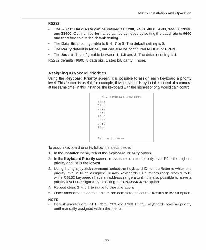
35
Matrix Installation and Operation
RS232
• The RS232 Baud Rate can be defined as 1200, 2400, 4800, 9600, 14400, 19200and 38400. Optimum performance can be achieved by setting the baud rate to 9600and therefore this is the default setting.
• The Data Bit is configurable to 5, 6, 7 or 8. The default setting is 8.
• The Parity default is NONE, but can also be configured to ODD or EVEN.
• The Stop bit is configurable between 1, 1.5 and 2. The default setting is 1.
RS232 defaults: 9600, 8 data bits, 1 stop bit, parity = none.
Assigning Keyboard PrioritiesUsing the Keyboard Priority screen, it is possible to assign each keyboard a prioritylevel. This feature is useful, for example, if two keyboards try to take control of a cameraat the same time. In this instance, the keyboard with the highest priority would gain control.
To assign keyboard priority, follow the steps below:
1. In the Installer menu, select the Keyboard Priority option.
2. In the Keyboard Priority screen, move to the desired priority level. P1 is the highestpriority and P8 is the lowest.
3. Using the right joystick command, select the Keyboard ID number/letter to which thispriority level is to be assigned. RS485 keyboards ID numbers range from 1 to 8,while RS232 keyboards have an address range a to d. It is also possible to leave apriority level unassigned by selecting the UNASSIGNED option.
4. Repeat steps 2 and 3 to make further alterations.
5. Once amendments on this screen are complete, select the Return to Menu option.
NOTE• Default priorites are: P1:1, P2:2, P3:3, etc. P8:8. RS232 keyboards have no priority
until manually assigned within the menu.
6.2 Keyboard Priority
P1:1P2:aP3:2P4:bP5:3P6:cP7:4P8:d
Return to Menu
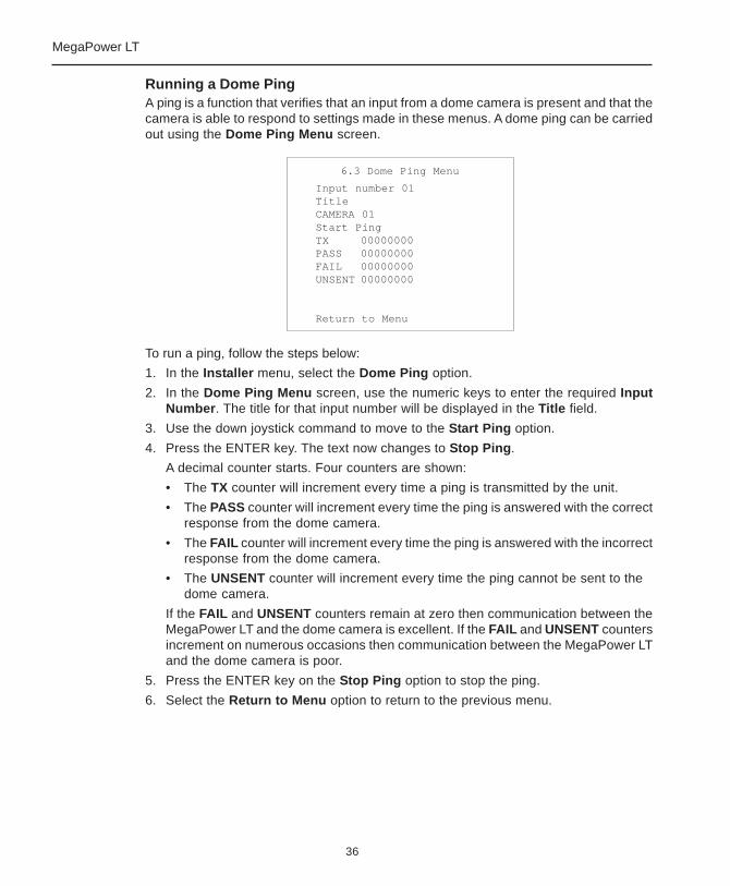
36
MegaPower LT
Running a Dome PingA ping is a function that verifies that an input from a dome camera is present and that thecamera is able to respond to settings made in these menus. A dome ping can be carriedout using the Dome Ping Menu screen.
To run a ping, follow the steps below:
1. In the Installer menu, select the Dome Ping option.
2. In the Dome Ping Menu screen, use the numeric keys to enter the required InputNumber. The title for that input number will be displayed in the Title field.
3. Use the down joystick command to move to the Start Ping option.
4. Press the ENTER key. The text now changes to Stop Ping.
A decimal counter starts. Four counters are shown:
• The TX counter will increment every time a ping is transmitted by the unit.
• The PASS counter will increment every time the ping is answered with the correctresponse from the dome camera.
• The FAIL counter will increment every time the ping is answered with the incorrectresponse from the dome camera.
• The UNSENT counter will increment every time the ping cannot be sent to thedome camera.
If the FAIL and UNSENT counters remain at zero then communication between theMegaPower LT and the dome camera is excellent. If the FAIL and UNSENT countersincrement on numerous occasions then communication between the MegaPower LTand the dome camera is poor.
5. Press the ENTER key on the Stop Ping option to stop the ping.
6. Select the Return to Menu option to return to the previous menu.
6.3 Dome Ping Menu
Input number 01TitleCAMERA 01Start PingTX 00000000PASS 00000000FAIL 00000000UNSENT 00000000
Return to Menu

37
Matrix Installation and Operation
Vertical Phase SynchronisationThe Installer menu has an synchronisation option which, if enabled, will cause theMegaPower LT to transmit a vertical phase signal to all video inputs. This signal can beused by compatible cameras to synchronise.
To enable this option, use the down joystick command to move to the VPSynch optionand use the right joystick command to set the parameter to Enabled.
Saving and Restoring DefaultsThe feature can only be used if all Cameras connected to the MPLT require VPSynch. If not, a visible Synch Pulse will roll through video of cameras not requiringpulse.
The Installer menu has an option which allows users to save their system settings toflash memory. This can be done by selecting the Save to User Defaults option. This isuseful if the configuration of the system is changed in error in the future. The user canthen restore the saved defaults using the Restore Saved Defaults option.
There is also a Restore Factory Defaults option which when selected, returns theMegaPower LT to factory settings.
Restore Factory Defaults will erase any previously saved programming (i.e. therewill be no user programming to restore).
To select any of these options, use the down joystick command to move to the requiredoption and press the ENTER key to select it.
6 Installer Menu
S/W Ver 1.xx6.1 System Options6.2 Keyboard Priority6.3 Dome Ping
VPSynch: DISABLEDSave to User DefaultsRestore User DefaultsRestore Factory Defaults
Return to Menu
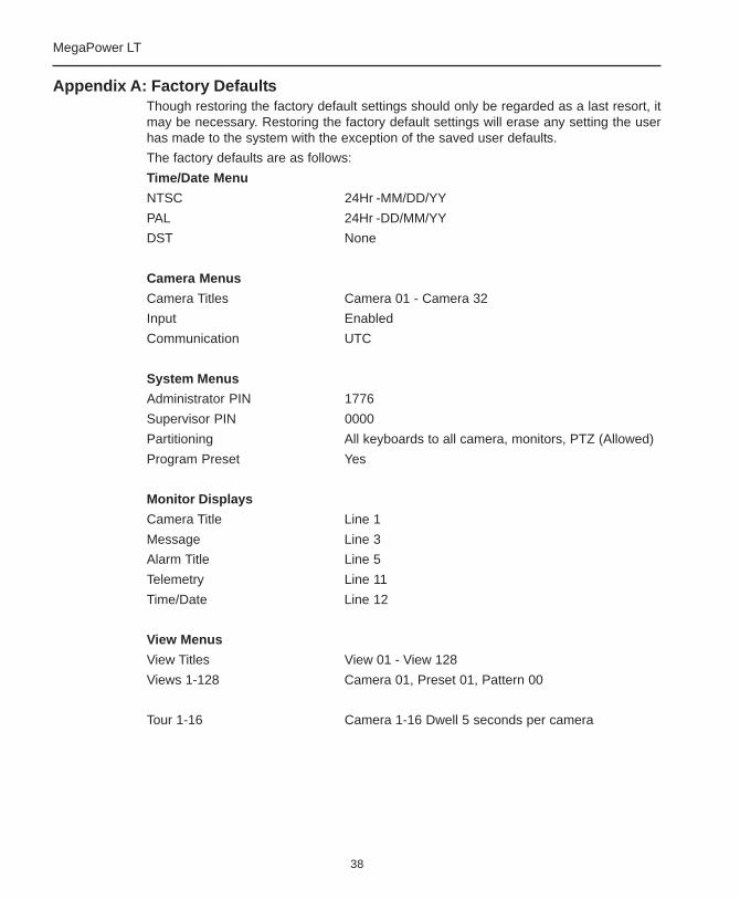
38
MegaPower LT
Appendix A: Factory DefaultsThough restoring the factory default settings should only be regarded as a last resort, itmay be necessary. Restoring the factory default settings will erase any setting the userhas made to the system with the exception of the saved user defaults.
The factory defaults are as follows:
Time/Date Menu
NTSC 24Hr -MM/DD/YY
PAL 24Hr -DD/MM/YY
DST None
Camera Menus
Camera Titles Camera 01 - Camera 32
Input Enabled
Communication UTC
System Menus
Administrator PIN 1776
Supervisor PIN 0000
Partitioning All keyboards to all camera, monitors, PTZ (Allowed)
Program Preset Yes
Monitor Displays
Camera Title Line 1
Message Line 3
Alarm Title Line 5
Telemetry Line 11
Time/Date Line 12
View Menus
View Titles View 01 - View 128
Views 1-128 Camera 01, Preset 01, Pattern 00
Tour 1-16 Camera 1-16 Dwell 5 seconds per camera
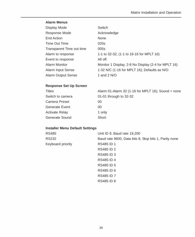
39
Matrix Installation and Operation
Alarm Menus
Display Mode Switch
Response Mode Acknowledge
End Action None
Time Out Time 020s
Transparent Time out time 005s
Alarm to response 1-1 to 32-32; (1-1 to 16-16 for MPLT 16)
Event to response All off.
Alarm Monitor Monitor 1 Display, 2-8 No Display (2-4 for MPLT 16)
Alarm Input Sense 1-32 N/C (1-16 for MPLT 16); Defaults as N/O
Alarm Output Sense 1 and 2 N/O
Response Set Up Screen
Titles Alarm 01-Alarm 32 (1-16 for MPLT 16); Sound = none
Switch to camera 01-01 through to 32-32
Camera Preset 00
Generate Event 00
Activate Relay 1 only
Generate Sound Short
Installer Menu Default Settings
RS485 Unit ID 9, Baud rate 19,200
RS232 Baud rate 9600, Data bits 8, Stop bits 1, Parity none
Keyboard priority RS485 ID 1
RS485 ID 2
RS485 ID 3
RS485 ID 4
RS485 ID 5
RS485 ID 6
RS485 ID 7
RS485 ID 8

40
MegaPower LT
Appendix B: Password RecoveryA password recovery system is provided so that a password can be recovered in theevent of a password being forgotten.
To use the password recovery system to enter the menu system:
1. Select a monitor by entering the monitor number and pressing the MONITOR ( )key.
2. Press the SHIFT ( ) key and the MENU ( ) key. The menu access screen is nowdisplayed prompting for a password.
3. Press the FUNCTION ( ) key.
4. Simultaneously press the MENU ( ), MULTISCREEN ( ) and FREEZE ( )keys. A 4-digit number is generated and displayed on the monitor.
5. Telephone your supplier immediately where you will be asked for this number.
6. You will be provided with a randomly generated temporary password that complementsthis number. Enter this password and press the ENTER key (can only be used once).
7. You will now have access to the installer menu system where you must use theSystem menu to re-create your own passwords.

41
Matrix Installation and Operation
Appendix C: Specifications
TelemetryAmerican Dynamics Up The Cable (UTC) and Sensornet telemetrycontrol for Tyco Security Products-Video Systems.
VideoConnector type BNC
Bandwidth /Frequency response + 0.5dB to 6 MHz
S/N Ratio –60dB (Vp-p vs. Vrms noise)
Cross Talk
Adjacent channel –45dB (at 3.58 MHz)
Input to input –55dB (at 3.58 MHz)
Differential delay + 1.0o
Differential phase < 0.5 o
Differential Gain < 1.5 %
Tilt < 0.5%
Loop through with automatic termination
Alarm InputMegaPower LT 32x8 32 Inputs
MegaPower LT 16x4 16 Inputs
Connectors type Plug assembly
1 ground connection for every 4 alarm inputs
Auxiliary OutputThe auxiliary output connector is of a plug assembly type. Thereare a maximum of two voltage free output relays available,providing normally-open and normally-closed contacts.
Dip SwitchesThe dip switches are used for RS485 network and domecamera control biasing and termination.
Remote KeyboardThis connects to RS232 and RS485 remote keyboards and isa single RJ45 connector type. It provides an upload/downloadfunction for the UTC and matrix devices.
Power SourceClass 2 LPS 12V DC source. Cable retention provided.
Physical SpecificationsDimensions: Height = 90mm (Unit 2u)
Width = 445mm
Depth = 185mm
Weight: 3.5Kg
19” rack mount adapter / wall mount adapter is available.
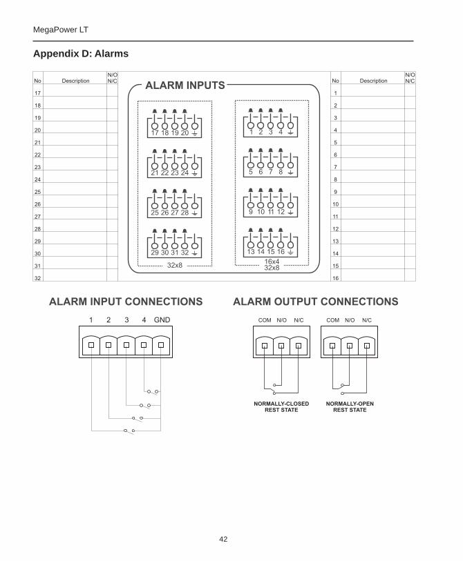
42
MegaPower LT
Appendix D: Alarms
43
Matrix Installation and Operation
Appendix E: Keyboard Installation Addendum
RS-232 PROTOCOL
UP to four RS-232 controllers can be connected to the MPLT (requires AD2081 Rs-232port expander). Controllers can be ADDTE, AD2088, ADC200/300, or ADCC1100keyboards.
• A maximum of 1000 feet @ 1200 baud
• Repeat Mode must be set to OFF
• Use recommended BELDEN cable 88102 (plenum)
• Use recommended BELDEN cable 9729 (non-plenum)
Note: RS232 range is specified with the recommended cable types and at 1200 baudonly.
RS-485 Protocol Guideline
• Up to eight RS-485 controllers can be connected to the MPLT. Only ADCC200 orADCC300 keyboard supports RS-485 protocol.
• A maximum of 3300 feet @ 1200 baud.
• One shielded twisted pair, 22 AWG, BELDEN cable 8761 (plenum)
• One shielded twisted pair, 22 AWG, BELDEN cable 8760 (non-plenum)
• Requires biasing/termination on RS-485 network such as matrix, keyboard or dome.
• Bi-directional data flow
• Up to three matrixes can be daisy chained
SENSORNET Protocol Guideline
• Up to 32 Sensornet devices per Sensornet link can be connected to the MPLT.Sensornet devices include other MPLT's or domes.
• Maximum of four repeaters in a Sensornet network.
• Use recommended BELDEN cable 88442 (plenum)
• Use recommended BELDEN cable 9407 (non-plenum)
• Follow Sensornet termination rules (8000-0970-01)
AD UTC Protocol Guideline
• Supports ULTRA 7 vers.1.05 or higher dome control via coax cable
• Bi-directional communication capability
• Data rate of 38400 BPS or greater
• Maximum of 2300 feet (700 metres)

44
MegaPower LT
Configuring the AD2088 keyboard baud rate:
1. Turn the key to MENU
2. Press the “F1” button
3. The word BAUD should be displayed on the keyboard LED screen
4. Use the “NEXT” or “LAST” button to change to the desired baud rate (1200, 2400,4800, 9600, 19200, or 38400)
5. When done, turn the key back to "OPERATE"
CHANGING REPEAT MODE TO OFF ON THE AD2088 KEYBOARD:
1. Turn the key to “MENU”, and then press the “F1” button
2. The worf “BAUD” should be displayed. Press the “PROG” button BUTTON UNTILYOU SEE “AUTO RPT = AUTO or ON”.
3. USE THE “NEXT” OR “LAST” BUTTON TO CHANGE IT TO “OFF”
4. TURN THE KEY BACK TO “OPERATE”
Configuring the ADTTE Touch Tracker baud rate:
1. Press the “+” button to enter programming mode
2. Enter 1200 and press F1 for 1200 baud (baud rate can be 1200, 2400, or 9600)
3. Press the “-” button to exit programming mode
CHANGING REPEAT MODE TO OFF ON THE ADTTE TOUCH TRACKER:
1. Press the “+” button to enter programming mode
2. Enter 200, F1
3. Press the “-” button to exit programming mode
Configuring theADCC200/300 keyboard baud rate:
1. Setting the protocol:
a. Access SPECIAL CONFIG MENU by pressing SHIFT and within 5 secondsof applying power to the keyboard.
b. Press the VCR RECORD button
c: Press number 1 FOR RS-485 OR 2 for RS-232 and then press the ENTER button
2. Setting the ADCC200/300 baud rate:
a. Access SPECIAL CONFIG MENU by pressing SHIFT and within 5 secondsof applying power to the keyboard.
b. Press the VCR REWIND button
c: Press number 1 FOR RS-485 OR 2 for RS-232 and then press the ENTER button

45
Matrix Installation and Operation
Enter 1=1200 baud + ENTER button
2=2400 baud + ENTER button (or 0 + ENTER to see next page)
3=4800 baud + ENTER button
4=9600 baud + ENTER button (or 0 + ENTER to see next page)
5=19200 baud + ENTER button
6=38400 baud + ENTER button (or 0 + ENTER to see next page)
7=57600 baud + ENTER button
Changing the repeat mode to off on the ADCC200/300 keyboard:
1. Access SPECIAL CONFIG MENU by pressing SHIFT and within 5 secondsof applying power to the keyboard.
2. Press the TELEMETRY button
3. Select 2 for “MAKE/BREAK” and press the “ENTER” button (ADCC1100 OR ADCC200/300 must be set to repeat mode = off referred to as “MAKE/BREAK” )
Configuring the ADCC1100 keyboard baud rate:
1. Press the PROGRAM tab key
2. Press the NEXT soft key
3. Press the BAUD soft key to cycle the baud rate (1200, 2400, 4800, 9600, 19200, or38400)
4. Press the OPERATE tab key to return to normal mode
Changing the repeat mode to off on the ADCC1100 keyboard:
1. Press the PROGRAM tab key
2. Press the NEXT soft key
3. Select “MP48” soft key for repeat mode OFF or “AD1024” for repeat mode ON(ADCC1100 or ADCC200/300 must be set to repeat mode = OFF)
4. Press the OPERATE tab key to return to normal mode
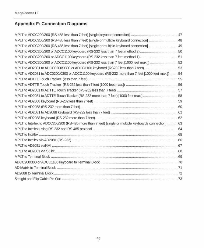
46
MegaPower LT
Appendix F: Connection Diagrams
MPLT to ADCC200/300 (RS-485 less than 7 feet) [single keyboard conection] .............................................. 47
MPLT to ADCC200/300 (RS-485 less than 7 feet) [single or multiple keyboard connection] ............................ 48
MPLT to ADCC200/300 (RS-485 less than 7 feet) [single or multiple keyboard connection] ............................ 49
MPLT to ADCC200/300 or ADCC1100 keyboard (RS-232 less than 7 feet method 2) ..................................... 50
MPLT to ADCC200/300 or ADCC1100 keyboard (RS-232 less than 7 feet method 1) ..................................... 51
MPLT to ADCC200/300 or ADCC1100 keyboard (RS-232 less than 7 feet [1000 feet max.]) ........................... 52
MPLT to AD2081 to ADCC0200/0300 or ADCC1100 keyboard (RS232 less than 7 feet) ................................ 53
MPLT to AD2081 to ADC0200/0300 or ADCC1100 keyboard (RS-232 more than 7 feet [1000 feet max.]) ....... 54
MPLT to ADTTE Touch Tracker (less than 7 feet) ........................................................................................ 55
MPLT to ADTTE Touch Tracker (RS-232 less than 7 feet [1000 feet max.]) ................................................... 56
MPLT to AD2081 to ADTTE Touch Tracker (RS-232 less than 7 feet) ............................................................ 57
MPLT to AD2081 to ADTTE Touch Tracker (RS-232 more than 7 feet) [1000 feet max.] .................................. 58
MPLT to AD2088 keyboard (RS-232 less than 7 feet) .................................................................................. 59
MPLT to AD2088 (RS-232 more than 7 feet) ............................................................................................... 60
MPLT to AD2081 to AD2088 keyboard (RS-232 less than 7 feet) .................................................................. 61
MPLT to AD2088 keyboard (RS-232 more than 7 feet) ................................................................................. 62
MPLT to Intellex to ADCC200/300 (RS-485 more than 7 feet) [single or multiple keyboards connection] .......... 63
MPLT to Intellex using RS-232 and RS-485 protocol .................................................................................... 64
MPLT to Intellex ......................................................................................................................................... 65
MPLT to Intellex via AD2081 (RS-232) ........................................................................................................ 66
MPLT to AD2081 viaKMI ............................................................................................................................ 67
MPLT to AD2081 via S3 kit ......................................................................................................................... 68
MPLT to Terminal Block ............................................................................................................................. 69
ADCC200/300 or ADCC1100 keyboard to Terminal Block ............................................................................ 70
AD Matrix to Terminal Block ....................................................................................................................... 71
AD2088 to Terminal Block .......................................................................................................................... 72
Straight and Flip Cable Pin Out .................................................................................................................. 73
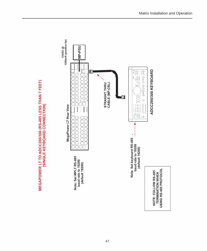
47
Matrix Installation and Operation
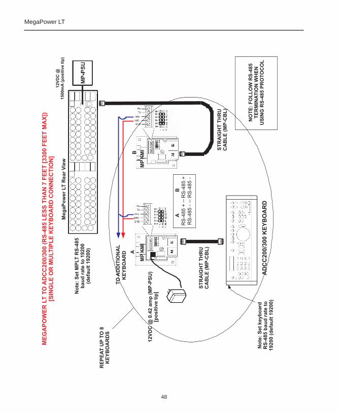
48
MegaPower LT
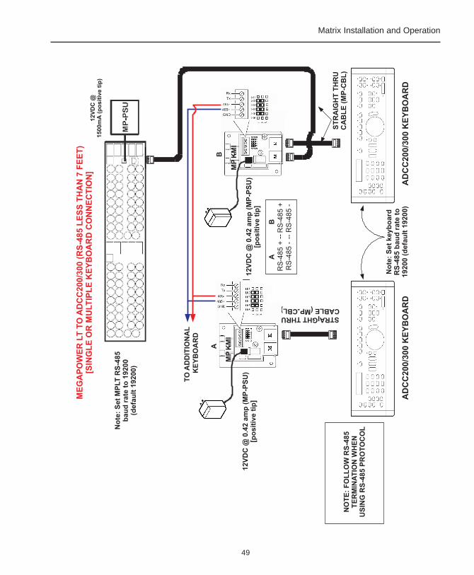
49
Matrix Installation and Operation
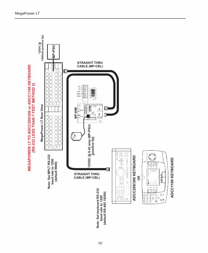
50
MegaPower LT
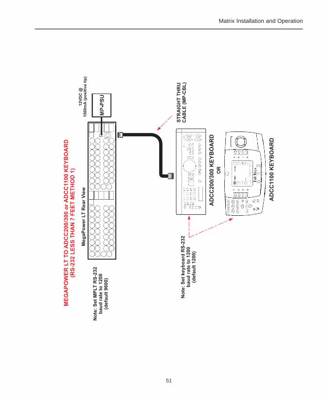
51
Matrix Installation and Operation
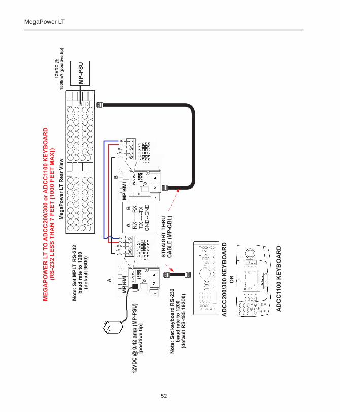
52
MegaPower LT
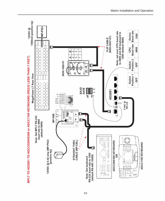
53
Matrix Installation and Operation
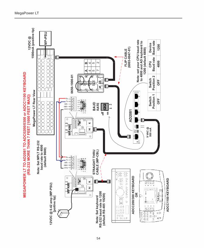
54
MegaPower LT
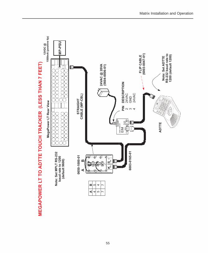
55
Matrix Installation and Operation
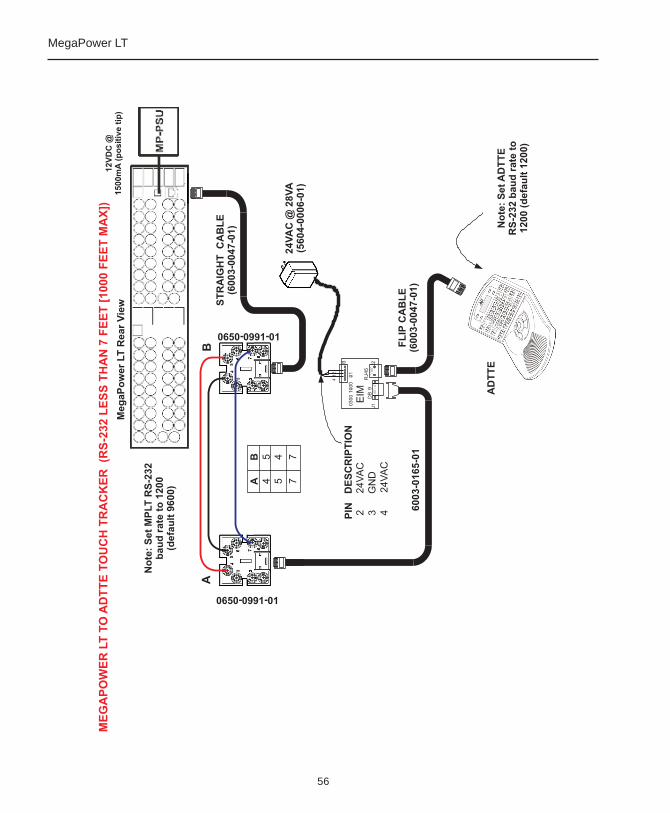
56
MegaPower LT
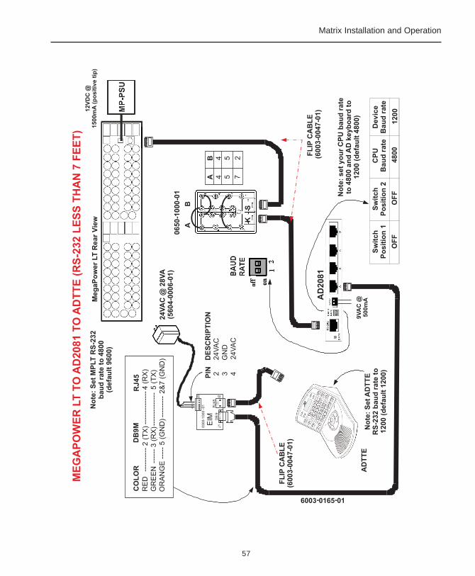
57
Matrix Installation and Operation
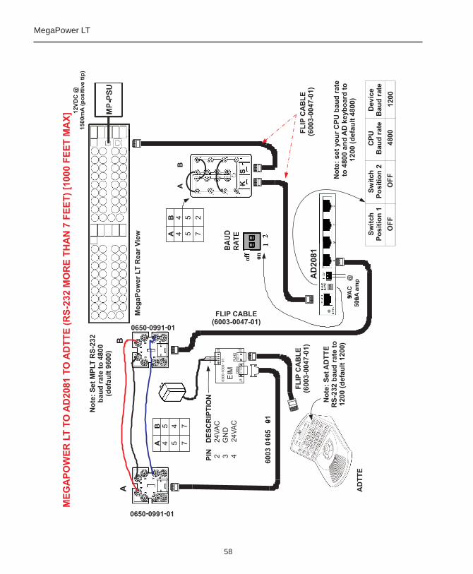
58
MegaPower LT

59
Matrix Installation and Operation
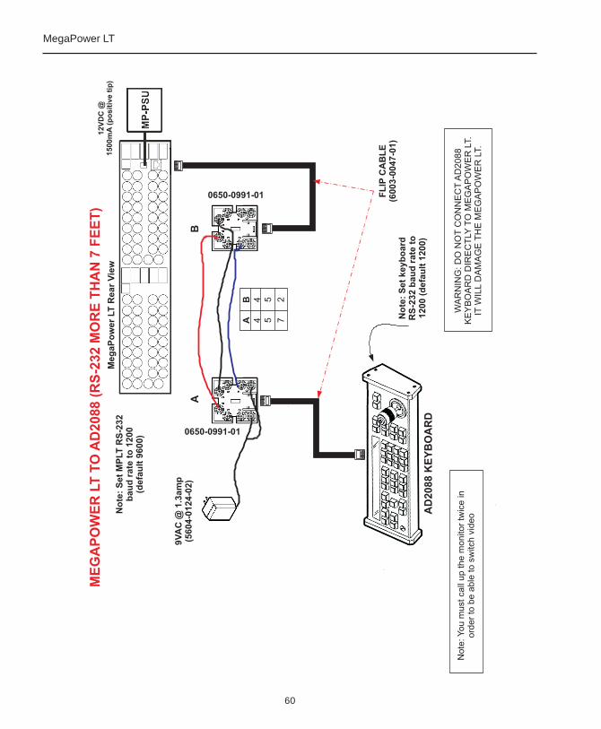
60
MegaPower LT
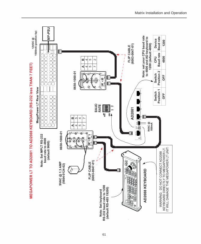
61
Matrix Installation and Operation
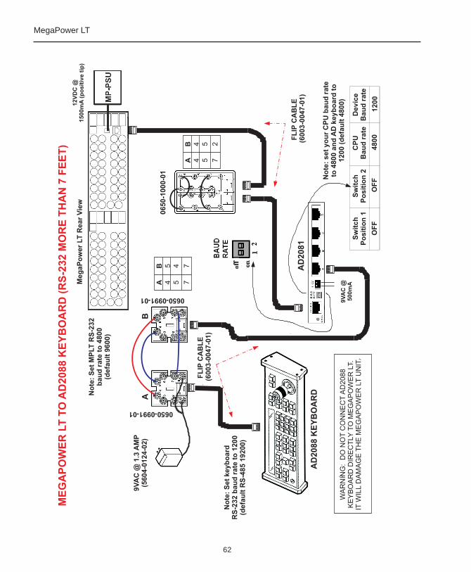
62
MegaPower LT
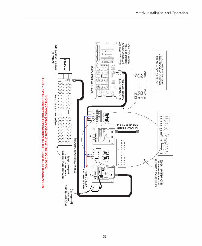
63
Matrix Installation and Operation

64
MegaPower LT

65
Matrix Installation and Operation
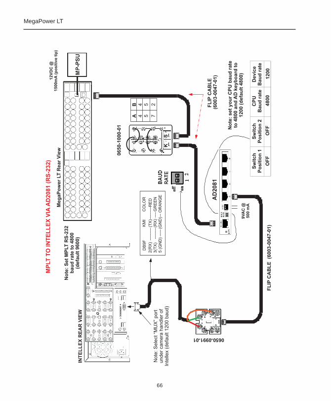
66
MegaPower LT
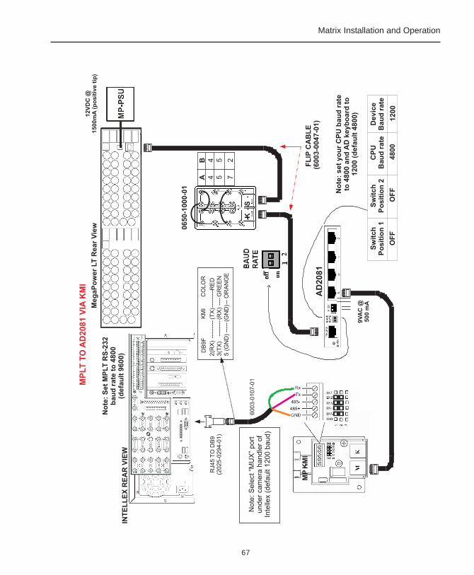
67
Matrix Installation and Operation
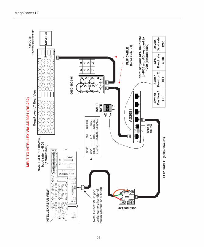
68
MegaPower LT

69
Matrix Installation and Operation
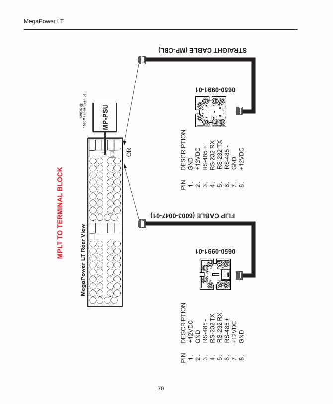
70
MegaPower LT
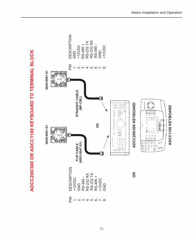
71
Matrix Installation and Operation
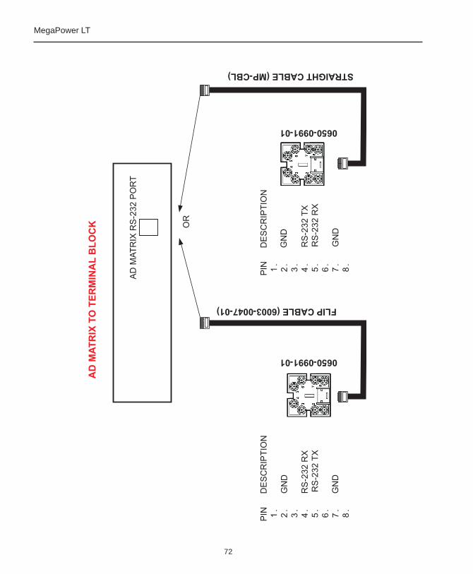
72
MegaPower LT
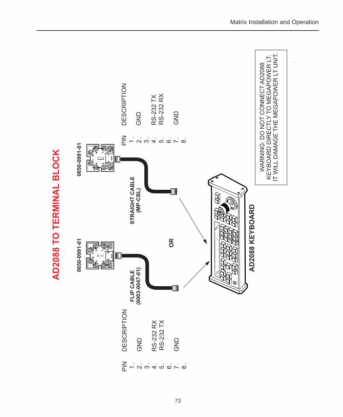
73
Matrix Installation and Operation
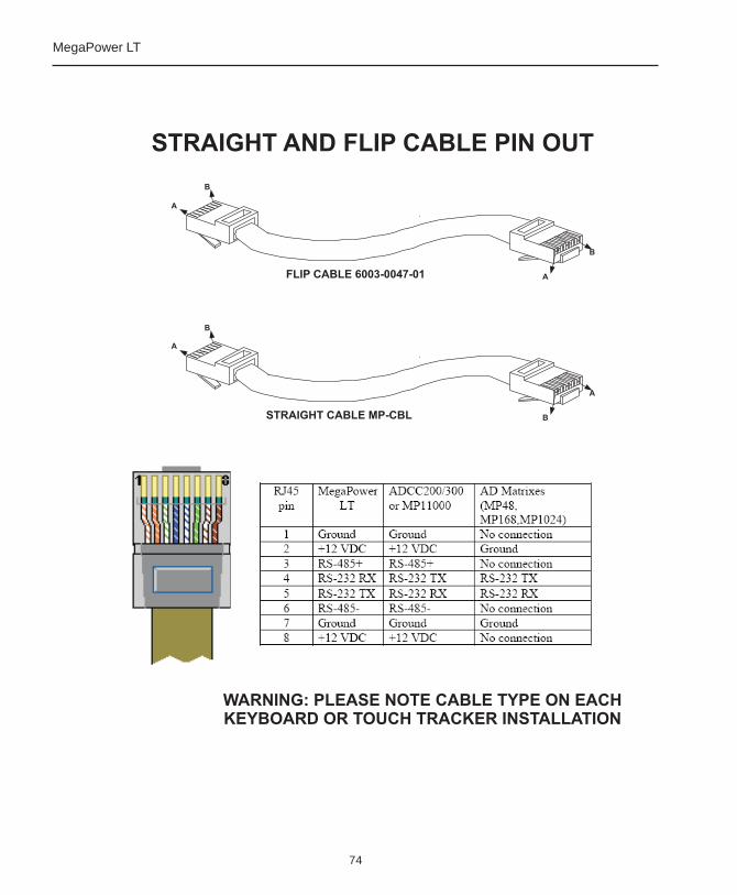
74
MegaPower LT

75
Matrix Installation and Operation

76
MegaPower LT
Please visit our website for more informationwww.americandynamics.net
© 2003 American DynamicsProduct specifications subject to change without noticeCertain product names mentioned herein may be trade namesand/or registered trademarks of other companies MP-LTHB-3