megaflo he a5 Issue 2 - Heatrae Sadia · The Megatech unvented water heater can be fed directly...
36
36 00 5823 Issue 4 tech Fitting and using the Megatech Solar unvented mains pressure water heater Solar 36005942 issue 4
Transcript of megaflo he a5 Issue 2 - Heatrae Sadia · The Megatech unvented water heater can be fed directly...
����
���
��
1
tech
36 00 5823 Issue 4
tech
Fitting and using the Megatech Solar unventedmains pressure water heater
Solar
36005942 issue 4

22
techtech
ContentsSECTION PAGE
1 INTRODUCTION ........................................................................... 3
2 GENERAL REQUIREMENTS ...................................................... 4
3 INSTALLATION - GENERAL ......................................................... 6
4 INSTALLATION - SOLAR PRIMARY ............................................ 15
5 INSTALLATION - DIRECT UNITS ................................................. 16
6 INSTALLATION - AUXILLARY COIL (INDIRECT UNITS) ............ 18
7 COMMISSIONING ....................................................................... 23
8 USER INSTRUCTIONS ................................................................ 25
9 MAINTENANCE ........................................................................... 27
10 FAULT FINDING & SERVICING .................................................. 29
11 DIMENSIONS & SPECIFICATIONS ........................................... 32
12 GUARANTEE ................................................................................ 35
13 CONTACTS ................................................................................... 36
Con
tent
s
Please read and understand these instructions before starting work.
The information contained in these instructions details how to connectthe Megatech Solar water heater to a solar primary circuit. Other
controls will be necessary to provide control over the primary circuit,refer to the instructions supplied with the solar controls and ancillary
equipment for details of how to integrate them with the Megatech Solarunit.
Please leave this leaflet with the user following installation
����
���
��
3
tech
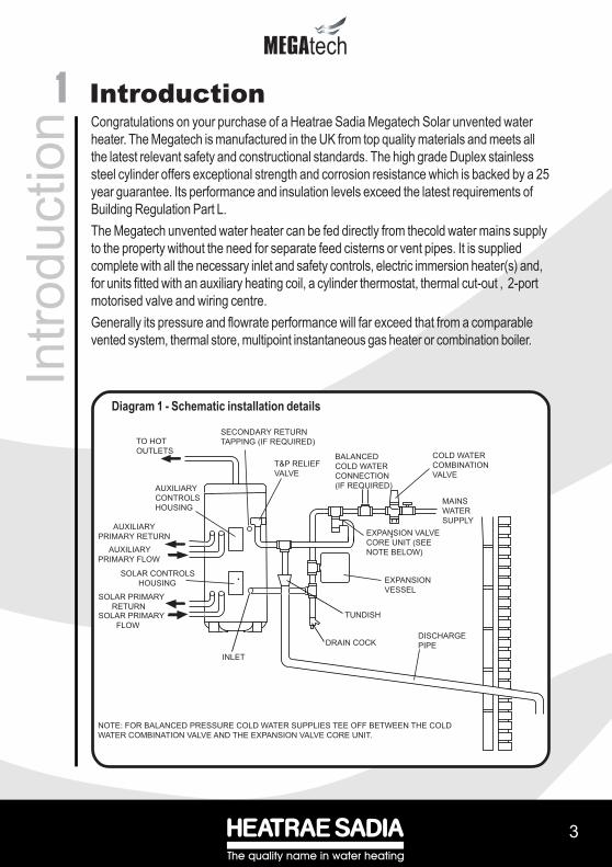
1Congratulations on your purchase of a Heatrae Sadia Megatech Solar unvented waterheater. The Megatech is manufactured in the UK from top quality materials and meets allthe latest relevant safety and constructional standards. The high grade Duplex stainlesssteel cylinder offers exceptional strength and corrosion resistance which is backed by a 25year guarantee. Its performance and insulation levels exceed the latest requirements ofBuilding Regulation Part L.The Megatech unvented water heater can be fed directly from thecold water mains supplyto the property without the need for separate feed cisterns or vent pipes. It is suppliedcomplete with all the necessary inlet and safety controls, electric immersion heater(s) and,for units fitted with an auxiliary heating coil, a cylinder thermostat, thermal cut-out , 2-portmotorised valve and wiring centre.Generally its pressure and flowrate performance will far exceed that from a comparablevented system, thermal store, multipoint instantaneous gas heater or combination boiler.
IntroductionIn
trodu
ctio
n
Diagram 1 - Schematic installation details
COLD WATER
COMBINATION
VALVE
BALANCED
COLD WATER
CONNECTION
(IF REQUIRED)
T&P RELIEF
VALVE
AUXILIARY
CONTROLS
HOUSING
AUXILIARY
PRIMARY RETURN
SOLAR PRIMARY
FLOW
INLET
DRAIN COCKDISCHARGE
PIPE
TUNDISH
SECONDARY RETURN
TAPPING (IF REQUIRED)TO HOT
OUTLETS
MAINS
WATER
SUPPLY
EXPANSION VALVE
CORE UNIT (SEE
NOTE BELOW)
NOTE: FOR BALANCED PRESSURE COLD WATER SUPPLIES TEE OFF BETWEEN THE COLD
WATER COMBINATION VALVE AND THE EXPANSION VALVE CORE UNIT.
SOLAR PRIMARY
RETURN
AUXILIARY
PRIMARY FLOW
SOLAR CONTROLS
HOUSING EXPANSION
VESSEL

44
techtech
IMPORTANT : PLEASE READ AND UNDERSTAND THESE INSTRUCTIONS BEFORE INSTALLINGTHE MEGATECH WATER HEATER. INCORRECT INSTALLATION MAY INVALIDATE GUARANTEE.THIS APPLIANCE IS NOT INTENDED FOR USE BY PERSONS (INCLUDING CHILDREN) WITHREDUCED PHYSICAL, SENSORY OR MENTAL CAPABILITIES, OR LACK OF KNOWLEDGE ANDEXPERIENCE, UNLESS THEY HAVE BEEN GIVEN SUPERVISION OR INSTRUCTION CONCERNINGTHE USE OF THE APPLIANCE BY A PERSON RESPONSIBLE FOR THEIR SAFETY.THE MEGATECH SOLAR MUST BE INSTALLED (SECTIONS 2 - 6), COMMISSIONED (SECTION 7)AND MAINTAINED (SECTIONS 9 - 10) BY A COMPETENT INSTALLER IN ACCORDANCE WITHBUILDING REGULATION G3 (ENGLAND AND WALES), TECHNICAL STANDARD P3 (SCOTLAND)OR BUILDING REGULATION P5 (NORTHERN IRELAND) AND THE WATER FITTING REGULATIONS(ENGLAND AND WALES) OR WATER BYELAWS (SCOTLAND). FOLLOWING INSTALLATION ANDCOMMISSIONING, THE OPERATION OF THE HEATER SHOULD BE EXPLAINED TO THE USER(SECTION 8) AND THESE INSTRUCTIONS LEFT WITH THEM FOR FUTURE REFERENCE.
2.1 COMPONENT CHECK LISTBefore commencing installation check that all the components for your Megatech Solar unit arecontained in the package. The following components are supplied as standard with your Megatechunit :• Factory fitted immersion heater (s) and thermal controls• Cold Water Combination Valve (comprises Isolating Valve, Pressure Reducing Valve,
Strainer, and Check Valve).• Expansion Core Unit (comprises Check Valve and Expansion Valve)• Expansion Vessel (including wall mounting bracket)• Factory fitted Temperature/Pressure Relief Valve (set at 90oC/10bar)• T&P Relief Valve Insulation Set• Drain Valve• Wiring Centre (CL units only)• Tundish (included in the Cold Water Combination Valve pack)• Factory fitted Auxiliary heating coil Thermostat and Thermal Cut-out (CL units only)• 2-port Motorised Valve (CL units only)• Lifting handle
2.2 SITING THE MEGATECH SOLAR (see Diagram 1)The Megatech Solar unit must be vertically floor mounted. It can be placed anywhere convenientprovided the discharge pipe(s) from its safety valves can be correctly installed. Areas that aresubject to freezing must be avoided. Ensure that the floor is of sufficient strength to support the “full”weight of the unit (refer to Tables 4 and 5 on page 33 for unit weights). Pipe runs should be kept asshort as possible for maximum economy. Access to associated controls, immersion heaters andcontrols housings should be possible for servicing and maintenance of the system (Note: controlshousings hinge open to the left hand side).Please do not install valves or pipework (except discharge pipe) within 50mm (2”) of the T&P reliefvalve to allow your insulation set to be fitted. The insulation set is important to ensure heat andenergy conservation. See section 3.9 for more information.To aid installation the Megatech Solar is provided with lifting points located in the base moulding anda lifting handle. The lifting handle should be fully threaded onto the outlet boss before use. Once theMegatech Solar is suitably positioned the lifting handle should be removed to allow connection of theoutlet pipework. The weights of the units are noted on the tables on page 33.
2 General RequirementsG
ener
al R
equi
rem
ents

����
���
��
5
tech
2.3 WATER SUPPLYBear in mind that the mains water supply to the property will be supplying both the hot and coldwater requirements simultaneously. It is recommended that the maximum water demandbe assessed and the water supply checked to ensure this demand can be met.NOTE: A high mains water pressure will not always guarantee high flow rates.Wherever possible the main supply pipe should be in 22mm. We suggest that the minimumsupply requirements should be 0.15 MPa (1.5 bar) working pressure and 20 litres per minuteflowrate. At these values outlet flowrates may be poor if several outlets are used simulta-neously, the higher the available pressure and flowrate the better the system performance willbe.The Megatech Solar has an operating pressure of 0.3 MPa (3 bar) which is controlled by theCold Water Combination Valve. The Cold Water Combination Valve can be connected to amaximum mains supply pressure of 1.6 MPa (16 bar). The water supply must be ofwholesome water quality (Fluid Category 1 as defined by the Water Supply Regulations 1999).
2.4 OUTLET/TERMINAL FITTINGS (TAPS, ETC.)The Megatech Solar can be used in conjunction with most types of terminal fittings. It isadvantageous in many mixer showers to have balanced hot and cold water supplies. In theseinstances the balanced cold water supply should be teed off the supply to the Megatechimmediately after the Cold Water Combination Valve (see Diagrams 4 and 5). Branches to colddrinking outlets should be taken before the valve.Outlets situated higher than the Megatech Solar unit will give outlet pressures lower than that atthe heater, a 10m height difference will result in a 0.1 MPa (1 bar) pressure reduction at theoutlet fitting.NOTE: Accessories should have a rated operating pressure of at least 0.8 MPa (8 bar).
2.5 LIMITATIONSThe Megatech Solar unvented water heater should not be used in any of the followinginstances:• Solid fuel boilers or any other boiler in which the energy input is not under effective
thermostatic control unless additional and appropriate safety measures are installed.• Gravity circulation primaries.• Steam heating plant unless additional and appropriate safety devices are installed.• Ascending spray type bidets or any other Class 5 back syphonage risk requiring that a
Type AA, AB, AD or AG air gap be employed.• Water supplies that have inadequate pressure or where the supply may be intermittent.• Situations where it is not possible to safely pipe away any discharge from the safety
valves.• Areas where the water consistently contains a high proportion of solids, eg. suspendedmatter that could block the strainer, unless adequate filtration can be ensured.• The installation must be carried out in accordance with the relevant requirements of:
• The appropriate Building Regulations: either The Building Regulations (England), TheBuilding Regulations (Scotland) or Building Regulations (Northern Ireland).• The Water Fittings Regulations (England and Wales) or Water Byelaws (Scotland).

66
techtech
33.1 PIPE FITTINGS
All pipe connections to the Megatech Solar are made via 22mm compression fittings directly to theunit (nuts and olives supplied). The fittings are also threaded 3/4” BSP male parallel should threadedpipe connections be required.
3.2 COLD WATER SUPPLYA 22mm cold water supply is recommended, however, if a 15mm (1/2”) supply exists whichprovides sufficient flow (see section 2.3) this may be used. More flow noise may be experiencedfrom small bore pipes due to the increased water velocity through them.The Cold Water Combination Valve supplied with the Megatech Solar incorporates a full flowisolating valve which will enable the Megatech to be isolated from the mains supply for maintenanceor servicing. To close the valve the black handle should be turned so that it lies at 90o to the directionof flow. To open turn the handle so that it lies parallel to the direction of flow.
3.3 COLD WATER COMBINATION VALVE (see Diagram 2)The Cold Water Combination Valve can be connected anywhere on the cold water mains supplyprior to the Megatech Solar unit. There is no requirement to site it close to the unit, it can be locatedat a point where the mains supply enters the premises if this is more convenient. The ExpansionValve connection must not be used for any other purpose.The Cold Water Combination Valve can be installed as a complete one-piece unit. The valveincorporates a factory set, non-adjustable Pressure Reducer/Strainer, an Expansion Valveconnection and a single Check Valve. The valve can be fitted in any orientation to suit theinstallation, however, ensure that the Valve is installed with the direction of flow arrows (stamped onthe side of the brass body) pointing towards the Megatech heater. Should you wish to site theExpansion Valve on the Cold Water Combination Valve this can be done by unscrewing theconnection nut beneath the Expansion Valve on the Expansion Core Unit and removing theExpansion Valve. The connecting nut and blanking plug should then be unscrewed from the ColdWater Combination Valve and replaced with the Expansion Valve. NOTE: IF THE EXPANSIONVALVE IS FITTED TO THE COLD WATER COMBINATION VALVE THE EXPANSION COREUNIT SHOULD NOT BE USED AS THE CHECK VALVE WITHIN IT WILL PREVENT FREEPASSAGE OF EXPANDED WATER TO THE EXPANSION VALVE. Ensure the discharge fromthe Expansion Valve can be correctly installed.If a balanced pressure cold water supply is required to a thermostatic shower mixer valve this maybe teed off the supply to the Megatech immediately after the Cold Water Combination Valve (seeDiagram 5). Branches to drinking water outlets should be taken before the valve to avoidthe possibility of warm expanded water being drawn from the tap.
3.4 EXPANSION CORE UNIT (see Diagram 3)Should a balanced pressure cold water supply be required for other cold water outlets theExpansion Core Unit supplied should be used. The Core Unit should be fitted into the pipework
Installation - GeneralIn
stal
latio
n - G
ener
al

����
���
��
7
tech
between the Cold Water Combination Valve and the Megatech Solar (Note direction of flowarrows). The cold water balanced draw off connection should be taken from between the ColdWater Combination Valve and the Expansion Core Unit (see Diagram 4). The ExpansionValve connection on the Cold Water Combination Valve should remain blanked off using theblanking nut and seal provided. Ensure the discharge from the Expansion Valve can becorrectly installed.
Diagram 2 - Cold Water Combination Valve
Diagram 3 - Expansion Core Unit
ISOLATING VALVE
MAINS IN
22MMCOMPRESSION
CONNECTION
PRESSURE REDUCINGVALVE HOUSING
PRESSURE REDUCINGVALVE CARTRIDGE
(3 BAR)
22MMCOMPRESSIONCONNECTION
OUTLET TOMEGAFLO
EXPANSION VALVECONNECTION (IFONE-PIECE VALVEIS REQUIRED)
TAKE NOTE OFFLOW DIRECTION
EXPANSION RELIEF VALVEDISCHARGE CONNECTION
EXPANSION RELIEF VALVE
FROM COLDWATER
COMBINATIONVALVE
OUTLET TOMEGAFLO
22MM COMPRESSIONCONNECTION
EXPANSION CORE UNIT(INCORPORATESCHECK VALVE)
MOUNTING NUT22MM COMPRESSIONCONNECTION
TAKE NOTE OFFLOW DIRECTION

88
techtech
Tund
ish
Meg
atec
hSo
lar
Dis
char
ge p
ipe
to a
tmos
pher
e(S
ee S
ectio
n 3.
9 “D
isch
arge
Pipe
wor
k“)
KEY
MC
WS
Mai
ns c
old
wat
er s
uppl
yH
WS
H
ot w
ater
ser
vice
SC
S
top
Coc
kD
OC
D
rain
Off
Coc
k
Tem
pera
ture
/Pre
ssur
eR
elie
f Val
ve
Bal
ance
d co
ld w
ater
draw
off
Bala
nced
HW
S a
ndM
CW
S to
bat
hroo
ms,
show
ers,
cloa
kroo
ms,
etc.
Isol
atin
g/R
egul
atin
gVa
lves
as
requ
ired
HW
S s
uppl
yEx
pans
ion
Cor
eU
nit (
com
bine
dEx
pans
ion
Rel
ief
Valv
e/C
heck
Val
ve)
SC
SC
DO
C
EXP
AN
SIO
NV
ESSE
L
Inco
min
g C
old
Wat
er M
ain
MC
WS
to K
itche
n(u
nbal
ance
d co
ldm
ains
sup
ply)
Col
d W
ater
Com
bina
tion
Valv
e in
corp
orat
ing
Pre
ssur
e R
educ
ing
Valv
e,Is
olat
ing
Valv
e, S
train
eran
d C
heck
Val
veN
B Ex
pans
ion
Valv
eta
ppin
g m
ust b
e bl
anke
dof
f
DO
CD
OC
DO
C
Diag
ram
4 - S
chem
atic
inst
allat
ion
diag
ram
usin
g Co
ld W
ater
Com
bina
tion
Valve
inco
njun
ctio
n with
Exp
ansio
n Cor
e Uni
t
Inst
alla
tion
- Gen
eral

����
���
��
9
tech
Diag
ram
5 - S
chem
atic
inst
allat
ion
diag
ram
usin
g Co
ld W
ater
Com
bina
tion
Valve
Tund
ish
Meg
atec
hSo
lar
Dis
char
ge p
ipe
to a
tmos
pher
e(S
ee S
ectio
n 3.
8 “D
isch
arge
P
ipew
ork“
)
KEY
MC
WS
Mai
ns c
old
wat
er s
uppl
yH
WS
H
ot w
ater
ser
vice
SC
S
top
Coc
kD
OC
D
rain
Off
Coc
k
Tem
pera
ture
/Pre
ssur
eR
elie
f Val
ve
Bal
ance
d co
ld w
ater
draw
off
to s
how
erm
ixer
val
ves
(Not
e:ta
ppin
g m
ust b
e m
in.
3m fr
om M
egaf
loin
let c
onne
ctio
n)B
alan
ced
HW
S a
ndM
CW
S to
eac
hsh
ower
.
Isol
atin
g/R
egul
atin
gVa
lves
as
requ
ired
HW
S s
uppl
y
SC
SC
DO
C
Inco
min
g C
old
Wat
er M
ain
Inco
min
g C
old
Wat
er M
ain
MC
WS
to K
itche
nan
d dr
inki
ng w
ater
outle
ts (u
nbal
ance
dco
ld m
ains
sup
ply)
Col
d W
ater
Com
bina
tion
Valv
e in
corp
orat
ing
Pres
sure
Red
ucin
g Va
lve,
Isol
atin
g Va
lve,
Stra
iner
and
Che
ck V
alve
and
Expa
nsio
n R
elie
f Val
ve
DO
CD
OC
DO
C
EXPA
NS
ION
VES
SEL
1010
techtech
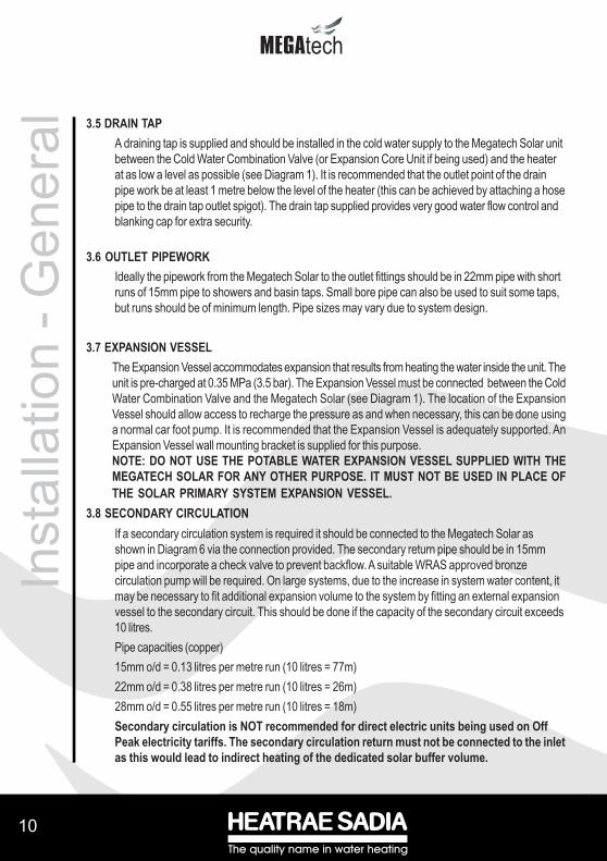
3.5 DRAIN TAPA draining tap is supplied and should be installed in the cold water supply to the Megatech Solar unitbetween the Cold Water Combination Valve (or Expansion Core Unit if being used) and the heaterat as low a level as possible (see Diagram 1). It is recommended that the outlet point of the drainpipe work be at least 1 metre below the level of the heater (this can be achieved by attaching a hosepipe to the drain tap outlet spigot). The drain tap supplied provides very good water flow control andblanking cap for extra security.
3.6 OUTLET PIPEWORKIdeally the pipework from the Megatech Solar to the outlet fittings should be in 22mm pipe with shortruns of 15mm pipe to showers and basin taps. Small bore pipe can also be used to suit some taps,but runs should be of minimum length. Pipe sizes may vary due to system design.
3.7 EXPANSION VESSELThe Expansion Vessel accommodates expansion that results from heating the water inside the unit. Theunit is pre-charged at 0.35 MPa (3.5 bar). The Expansion Vessel must be connected between the ColdWater Combination Valve and the Megatech Solar (see Diagram 1). The location of the ExpansionVessel should allow access to recharge the pressure as and when necessary, this can be done usinga normal car foot pump. It is recommended that the Expansion Vessel is adequately supported. AnExpansion Vessel wall mounting bracket is supplied for this purpose.NOTE: DO NOT USE THE POTABLE WATER EXPANSION VESSEL SUPPLIED WITH THEMEGATECH SOLAR FOR ANY OTHER PURPOSE. IT MUST NOT BE USED IN PLACE OFTHE SOLAR PRIMARY SYSTEM EXPANSION VESSEL.
3.8 SECONDARY CIRCULATIONIf a secondary circulation system is required it should be connected to the Megatech Solar asshown in Diagram 6 via the connection provided. The secondary return pipe should be in 15mmpipe and incorporate a check valve to prevent backflow. A suitable WRAS approved bronzecirculation pump will be required. On large systems, due to the increase in system water content, itmay be necessary to fit additional expansion volume to the system by fitting an external expansionvessel to the secondary circuit. This should be done if the capacity of the secondary circuit exceeds10 litres.Pipe capacities (copper)15mm o/d = 0.13 litres per metre run (10 litres = 77m)22mm o/d = 0.38 litres per metre run (10 litres = 26m)28mm o/d = 0.55 litres per metre run (10 litres = 18m)Secondary circulation is NOT recommended for direct electric units being used on OffPeak electricity tariffs. The secondary circulation return must not be connected to the inletas this would lead to indirect heating of the dedicated solar buffer volume.
Inst
alla
tion
- Gen
eral

����
���
��
11
tech
Diagram 6 - Secondary circulation connection
3.9 T&P RELIEF VALVE INSULATIONA set of insulating components is supplied with the Megaflo water heater and should be installed togain maximum heat and energy saving benefits. See Diagram 7 for installation instructions.
3.10 WARNINGSi) Under no circumstances should the factory fitted Temperature/Pressure Relief Valve
be removed other than by Authorised Heatrae Sadia personnel. To do so willinvalidate any guarantee or claim.
ii) The Cold Water Combination Valve must be fitted to the mains water supply to the Megatech unit.iii) No control or safety valves should be tampered with.iv) Water may drip from the discharge pipe of the pressure relief device (Expansion
Valve) and this pipe must be left open to atmosphere. The discharge pipe should notbe blocked or used for any other purpose.
SECONDARY RETURNCONNECTION
CHECK VALVE
SECONDARY CIRCULATION PUMP
OUTLET
SECONDARY RETURN
T&P RELIEFVALVE
DISCHARGEPIPEWORK
TO TUNDISH
'FEMALE'INSULATING
PIECE
'MALE'INSULATING
PIECE
DISCHARGEPIPE
PLASTICCOVER
CLIPINTO
PLACE!
A B
C D
Diagram 7 - Installation of T&P Insulating set

1212
techtech
3.11 DISCHARGE PIPEWORKIt is a requirement of Building Regulations that any discharge from an unvented system is conveyed towhere it is visible, but will not cause danger to persons in or about the building. The tundish and dischargepipes should be fitted in accordance with the requirements and guidance notes of Building Regulations.Building Regulation G3 Requirements and Guidance section 3.9 are reproduced in the following sec-tions.Information Sheet No. 33 available from the British Board of Agrément gives further advice on dischargepipe installation. For discharge pipe arrangements not covered by G3 Guidance or BBA Info SheetNo.33 advice should be sought from your local Building Control Officer.Any discharge pipe connected to the pressure relief devices (Expansion Valve and Temperature/Pressure Relief Valve) must be installed in a continuously downward direction and in a frost freeenvironment.
G3 REQUIREMENT“...there shall be precautions...to ensure that the hot water discharged from safety devices is safelyconveyed to where it is visible but will not cause danger to persons in or about the building.”
G3 GUIDANCE SECTION 3.9The discharge pipe (D1) from the vessel up to and including the tundish is generally supplied by themanufacturer of the hot water storage system. Where otherwise, the installation should include thedischarge pipe(s) (D1) from the safety device(s). In either case the tundish should be vertical, located inthe same space as the unvented hot water storage system and be fitted as close as possible and within500mm of the safety device e.g. the temperature relief valve.The discharge pipe (D2) from the tundish should terminate in a safe place where there is no risk topersons in the vicinity of the discharge, preferably be of metal and:a. be at least one pipe size larger than the nominal outlet size of the safety device unless its totalequivalent hydraulic resistance exceeds that of a straight pipe 9m long i.e. discharge pipes between 9mand 18m equivalent resistance length should be at least two sizes larger than the nominal outlet size ofthe safety device, between 18 and 27m at least 3 sizes larger , and so on. Bends must be taken intoaccount in calculating the flow resistance. Refer to Diagram 7, Table 1 and the worked example.An alternative approach for sizing discharge pipes would be to follow BS 6700:1987 Specification fordesign, installation, testing and maintenance of services supplying water for domestic use withinbuildings and their curtilages, Appendix E, section E2 and table 21.b. have a vertical section of pipe at least 300mm long below the tundish before any elbows or bends inthe pipework.c. be installed with a continuous fall.d. have discharges visible at both the tundish and the final point of discharge, but where this is notpossible or is practically difficult there should be clear visibility at one or other of these locations.
Inst
alla
tion
- Gen
eral

����
���
��
13
tech
Examples of acceptable discharge arrangements are:i. ideally below a fixed grating and above the water seal in a trapped gully.ii. downward discharges at low level; i.e. up to 100mm above external surfaces such as carparks, hard standings, grassed areas etc. are acceptable providing that where children may playor otherwise come into contact with discharges a wire cage or similar guard is positioned to preventcontact, whilst maintaining visibility.iii. discharges at high level; e.g. into a metal hopper and metal down pipe with the end of thedischarge pipe clearly visible (tundish visible or not) or onto a roof capable of withstanding hightemperature discharges of water and 3m from any plastics guttering system that would collect suchdischarges (tundish visible).iv. where a single pipe serves a number of discharges, such as in blocks of flats, the numberserved should be limited to not more than 6 systems so that any instalation discharging can betraced reasonably easily. The single common discharge pipe should be at least one pipe size largerthan the largest individual discharge pipe (D2) to be connected. If unvented hot water storagesystems are installed where discharges from safety devices may not be apparent i.e. in dwellingsoccupied by blind, infirm or disabled people, consideration should be given to the installation of anelectronically operated device to warn when discharge takes place.Note: The discharge will consist of scalding water and steam. Asphalt, roofing felt and non-metallicrainwater goods may be damaged by such discharges.
Worked example of discharge pipe sizingThe example below is for a G1/2 temperature relief valve with a discharge pipe (D2) having 4No. elbows and length of 7m from the tundish to the point of discharge.From Table 1:Maximum resistance allowed for a straight length of 22mm copper discharge pipe (D2) from aG1/2 temperature relief valve is 9.0m.Subtract the resistance for 4 No. 22mm elbows at 0.8m each = 3.2mTherefore the permitted length equates to: 5.8m5.8m is less than the actual length of 7m therefore calculate the next largest size.Maximum resistance allowed for a straight length of 28mm pipe (D2) from a G1/2 temperaturerelief valve equates to 18m.Subtract the resistance of 4 No. 28mm elbows at 1.0m each = 4.0mTherefore the maximum permitted length equates to: 14mAs the actual length is 7m, a 28mm (D2) copper pipe will be satisfactory.

1414
techtechIn
stal
latio
n - G
ener
al Valve outlet size Minimum size of discharge pipe
D1
Minimum size of discharge pipe D2 from tundish
Maximum resistance allow ed,
expressed as a length of stra ight
pipe (i.e . no e lbow s or bends)
Resistance created by each e lbow or bend
G1/2 15mm22mm 28mm 35mm
up to 9m up to 18m up to 27m
0.8m 1.0m 1.4m
G3/4 22mm28mm 35mm 42mm
up to 9m up to 18m up to 27m
1.0m 1.4m 1.7m
G1 28mm35mm 42mm 54mm
up to 9m up to 18m up to 27m
1.4m 1.7m 2.3m
Fixed grating
Discharge belowfixed grating(Building RegulationG3 section 3.9d givesalternative pointsof discharge)
Trappedgully
Discharge pipe (D2) from tundish,with continuous fall. See BuildingRegulation G3 section 3.9d i-iv,Table 4 and worked example
300mmminimum
500mm maximum
Metal discharge pipe (D1) fromTemperature relief valve to tundish
Tundish
Safety device(e.g. Temperaturerelief valve)
Table 1 - Sizing of copper discharge pipe (D2) for common T&P relief valve sizes
Diagram 8 - Schematic discharge pipe arrangement
����
���
��
15
tech
4In
stal
latio
n - S
olar
Prim
ary
Installation - Solar Primary4.1 CONNECTION TO SOLAR PRIMARY CIRCUIT
The lower (solar) coil of the Megatech Solar must be connected to a fully pumped solar primarycircuit. The connections (see diagram 17) are suitable for 22mm copper pipe direct to the compres-sion fittings provided. The connections are also threaded 3/4” BSP male parallel should BSPconnections be required.The solar primary circuit must have its own dedicated circulating pump, thermal and safety controlswhich must be installed as per the manufacturer’s instructions.
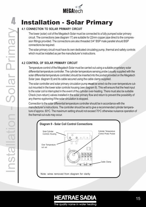
4.2 CONTROL OF SOLAR PRIMARY CIRCUITTemperature control of the Megatech Solar must be carried out using a suitable proprietary solardifferential temperature controller. The cylinder temperature sensing probe (usually supplied with thesolar differential temperature controller) should be inserted into the pocket provided on the MegatechSolar (see diagram 9) and its cable secured using the cable clamp supplied.The solar controller and solar primary circulation pump must be wired via the over-temperature cut-out mounted in the lower solar controls housing (see diagram 9). This will ensure that the heat inputto the solar coil is interrupted in the event of the cylinder over-heating. There must also be suitableCheck (non-return) valves installed in the solar primary flow and return to prevent the possibility ofany thermo-syphoning if the solar circulation is stopped.Connection to the solar differential temperature controller should be in accordance with themanufacturer’s instructions. The controller should be set to give a recommended cylinder tempera-ture of approx. 60oC. The maximum setting should not exceed 70oC otherwise nuisance operation ofthe thermal cut-outs may occur.
Diagram 9 - Solar Coil Control Connections
Cylinder TemperatureControl Probe Pocket
Cable Clamp
Solar CylinderControls Housing
Over Temperaturecut out
Note: wires removed from diagram for clarity

1616
techtechIn
stal
latio
n - D
irect
uni
ts 5.1 IMMERSION HEATER(S)The Megatech Solar Direct is supplied with two factory fitted immersion heaters. Each immersionheater is rated 3kW at 240V.To remove the immersion heater:Ensure the cylinder is drained of water first. Open the cover to the upper immersion heater. Unplugthe thermostat from the element by gently pulling the thermostat outwards. Unscrew the brassbacknut using the key spanner provided. Remove the immersion heater assembly and sealinggasket from the boss.Replacement:Insert the immersion heater and sealing gasket into the required boss. Ensure that the sealing gasketis not displaced when inserting. It may be helpful to support the immersion heater using a roundbladed screwdriver inserted into one of the thermostat pockets. Hand tighten the brass backnut.Secure the immersion heater in position by tightening with the key spanner provided. Insert theblanking plate into the remaining boss ensuring the sealing gasket is not displaced when inserting.Hand tighten the brass backnut. Secure in position by tightening with the key spanner provided.If an additional immersion heater is required order Part No. 95 970 510.
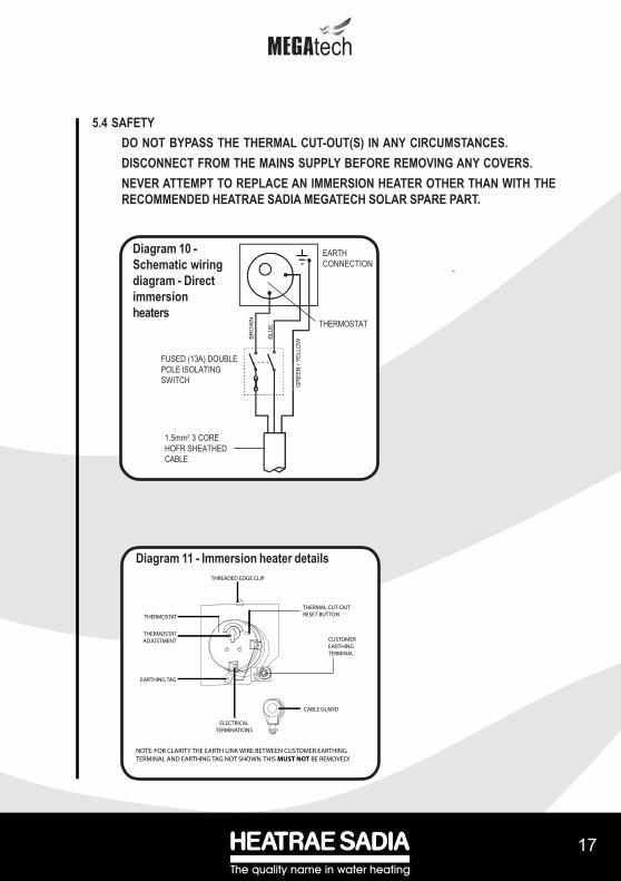
5.2 WIRING (see Diagram 10)All electrical wiring should be carried out by a competent electrician and be in accordance with thelatest I.E.E. Wiring Regulations. Each circuit must be protected by a suitable fuse and doublepole isolating switch with a contact separation of at least 3mm in both poles.The immersion heater(s) should be wired in accordance with Diagram 10. The immersion heatersMUST be earthed. The supply cable should be 1.5mm2 3 core HOFR sheathed and must be routedthrough the cable gland provided with the outer sheath of the cable firmly secured by tightening thescrew on the cable gland. Replace the immersion heater cover(s) before operating ensuring that thethreaded edge clip is in position to provide a suitable thread for the cover screw.DO NOT OPERATE THE IMMERSION HEATER(S) UNTIL THE MEGATECH SOLAR HASBEEN FILLED WITH WATER..
5.3 OPERATIONIt is recommended that the immersion heater thermostats are set to between position 4 and 5 (60o -65oC), however they can be set between 1 and 5 (10o and 70oC). The thermostat incorporates athermal cut-out that will switch off the immersion heater in the event of a thermostat failure. Thethermal cut-out reset button position is indicated on Diagram 10. DO NOT bypass the thermal cut-outin any circumstances.
5 Installation - Direct units
����
���
��
17
tech
5.4 SAFETYDO NOT BYPASS THE THERMAL CUT-OUT(S) IN ANY CIRCUMSTANCES.DISCONNECT FROM THE MAINS SUPPLY BEFORE REMOVING ANY COVERS.NEVER ATTEMPT TO REPLACE AN IMMERSION HEATER OTHER THAN WITH THERECOMMENDED HEATRAE SADIA MEGATECH SOLAR SPARE PART.
Diagram 10 -Schematic wiringdiagram - Directimmersionheaters
THERMOSTAT
FUSED (13A) DOUBLEPOLE ISOLATINGSWITCH
Diagram 11 - Immersion heater details
1.5mm2 3 COREHOFR SHEATHEDCABLE
BRO
WN
BLU
E
GR
EEN
/ YE
LLO
W
THERMAL CUT-OUTRESET BUTTON
ELECTRICALTERMINATIONS
CUSTOMEREARTHINGTERMINAL
CABLE GLAND
NOTE: FOR CLARITY THE EARTH LINK WIRE BETWEEN CUSTOMER EARTHINGTERMINAL AND EARTHING TAG NOT SHOWN. THIS MUST NOT BE REMOVED!
EARTHING TAG
THERMOSTATADJUSTMENT
THERMOSTAT
THREADED EDGE CLIP
EARTHCONNECTION
1818
techtechIn
stal
latio
n - A
uxilia
ry c
oil
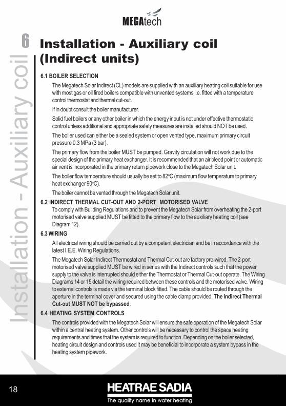
6.1 BOILER SELECTIONThe Megatech Solar Indirect (CL) models are supplied with an auxiliary heating coil suitable for usewith most gas or oil fired boilers compatible with unvented systems i.e. fitted with a temperaturecontrol thermostat and thermal cut-out.If in doubt consult the boiler manufacturer.Solid fuel boilers or any other boiler in which the energy input is not under effective thermostaticcontrol unless additional and appropriate safety measures are installed should NOT be used.The boiler used can either be a sealed system or open vented type, maximum primary circuitpressure 0.3 MPa (3 bar).The primary flow from the boiler MUST be pumped. Gravity circulation will not work due to thespecial design of the primary heat exchanger. It is recommended that an air bleed point or automaticair vent is incorporated in the primary return pipework close to the Megatech Solar unit.The boiler flow temperature should usually be set to 82oC (maximum flow temperature to primaryheat exchanger 90oC).The boiler cannot be vented through the Megatech Solar unit.
6.2 INDIRECT THERMAL CUT-OUT AND 2-PORT MOTORISED VALVETo comply with Building Regulations and to prevent the Megatech Solar from overheating the 2-portmotorised valve supplied MUST be fitted to the primary flow to the auxiliary heating coil (seeDiagram 12).
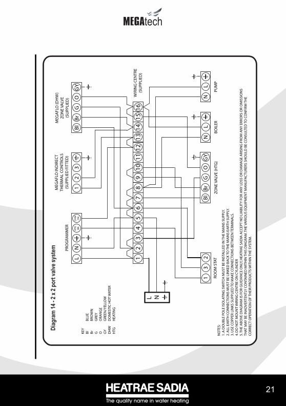
6.3 WIRINGAll electrical wiring should be carried out by a competent electrician and be in accordance with thelatest I.E.E. Wiring Regulations.The Megatech Solar Indirect Thermostat and Thermal Cut-out are factory pre-wired. The 2-portmotorised valve supplied MUST be wired in series with the Indirect controls such that the powersupply to the valve is interrupted should either the Thermostat or Thermal Cut-out operate. The WiringDiagrams 14 or 15 detail the wiring required between these controls and the motorised valve. Wiringto external controls is made via the terminal block fitted. The cable should be routed through theaperture in the terminal cover and secured using the cable clamp provided. The Indirect ThermalCut-out MUST NOT be bypassed.
6.4 HEATING SYSTEM CONTROLSThe controls provided with the Megatech Solar will ensure the safe operation of the Megatech Solarwithin a central heating system. Other controls will be necessary to control the space heatingrequirements and times that the system is required to function. Depending on the boiler selected,heating circuit design and controls used it may be beneficial to incorporate a system bypass in theheating system pipework.
6 Installation - Auxiliary coil(Indirect units)

����
���
��
19
tech
The Megatech Solar is compatible with most heating controls, examples of electrical circuits aregiven in Diagrams 14 and 15. However, other systems may be suitable, refer to thecontrols manufacturer’s instructions, supplied with the controls selected, foralternative system wiring schemes.
5.5 IMMERSION HEATERThe Megatech Solar indirect units (CL models) are supplied with an immersion heater whichcan be used as an alternative heat source should the boiler supply need to be isolated from theMegatech unit. The immersion heater is located within the controls housing. Refer to Sections4.2 and 4.3 and Diagram 10 for details of wiring and operation of the immersion heater.
Diagram 12 - Primary connections to indirect (CL) units
TO HOT OUTLETS
PRIMARYRETURN
PRIMARYFLOW
AIR VENT
2 PORT MOTORISEDVALVE (SUPPLIED)
INLET
AUXILLARYHEAT SOURCE
PRIMARYRETURN
PRIMARYFLOW
SOLAR PRIMARYCIRCUIT

2020
techtech
CABLE CLAMPS TERMINAL BLOCK
INDIRECTTHERMOSTAT
THERMOSTATADJUSTMENT
INDIRECTTHERMALCUT-OUT
INDIRECT THERMALCUT-OUT RESETBUTTON
NOTE:THE HOUSING COVER AND ELEMENT ASSEMBLY HAVE BEEN REMOVEDFROM THIS VIEW FOR CLARITY
Diagram 13 - Indirect controls housing details
Inst
alla
tion
- Ind
irect
uni
ts
����
���
��
21
tech
1
2
3
4
5
6
7
8
9
10
11 1
2 1
314
15
16
L N
N
L
N
L
Bl
Br
G
O
GY
Bl
Br
G
O
GY
1
2
3
L
NH
TG ON
DH
WO
N
PUM
PB
OIL
ERZO
NE
VALV
E (H
TG)
MEG
AFL
O (D
HW
)ZO
NE
VALV
E(S
UPP
LIED
) WIR
ING
CEN
TRE
(SU
PPLI
ED)
PRO
GRA
MM
ER
MEG
AFL
O IN
DIR
ECT
THER
MA
L C
ON
TRO
LS(S
UPP
LIED
FIT
TED
)
1
3
2
ROO
M S
TAT
NO
TES:
1. A
DO
UB
LE P
OLE
ISO
LATI
NG
SW
ITC
H M
UST
BE
INST
ALL
ED IN
TH
E M
AIN
S SU
PPLY
.2.
ALL
EA
RTH
CO
NN
ECTI
ON
S M
UST
BE
LIN
KED
BA
CK
TO
TH
E M
AIN
S EA
RTH
SU
PPLY
.3.
USE
CO
PPER
LIN
KS
SUPP
LIED
TO
MA
KE
CO
NN
ECTI
ON
S B
ETW
EEN
TER
MIN
ALS
.4.
DO
NO
T M
OU
NT
WIR
ING
CEN
TRE
ON
CY
LIN
DER
5. T
HE
AB
OV
E D
IAG
RAM
IS F
OR
GU
IDA
NC
E O
NLY
, HEA
TRA
E SA
DIA
AC
CEP
T N
O L
IAB
ILIT
Y F
OR
AN
Y L
OSS
OR
DA
MA
GE
ARI
SIN
G F
ROM
AN
Y E
RRO
RS O
R O
MIS
SIO
NS
THAT
MAY
BE
INA
DV
ERTE
NTL
Y C
ON
TAIN
ED W
ITH
IN T
HIS
DIA
GRA
M. T
HE
VARI
OU
S EQ
UIP
MEN
T M
AN
UFA
CTU
RERS
SH
OU
LD B
E C
ON
SULT
ED T
O C
ON
FIRM
TH
EC
ORR
ECT
OPE
RATI
ON
OF
THEI
R PR
OD
UC
TS W
ITH
IN T
HE
SYST
EM.
KEY
Bl
BLU
EB
r B
ROW
NG
G
REY
O
ORA
NG
EG
Y
GRE
EN/Y
ELLO
WD
HW
D
OM
ESTI
C H
OT
WAT
ERH
TG
HEA
TIN
G
Diag
ram
14 - 2
x 2 p
ort v
alve s
yste
m

2222
techtechIn
stal
latio
n - I
ndire
ct u
nits
1
2
3
4
5
6
7
8
9
10
11 1
2 1
314
15
16
L N
N
L
N
L
Bl
Br
G
O
GY
Bl
W
G
O
GY
1
2
3
L
NH
TG ON
DH
WO
N
PUM
PB
OIL
ER3-
PORT
MID
PO
SITI
ON
VA
LVE
MEG
AFL
O (D
HW
) 2-P
ORT
VALV
E (S
UPP
LIED
)
WIR
ING
CEN
TRE
(SU
PPLI
ED)
PRO
GRA
MM
ER
MEG
AFL
O IN
DIR
ECT
THER
MA
L C
ON
TRO
LS(S
UPP
LIED
FIT
TED
)
1
3
2
ROO
M S
TAT
NO
TES:
1. A
DO
UB
LE P
OLE
ISO
LATI
NG
SW
ITC
H M
UST
BE
INST
ALL
ED IN
TH
E M
AIN
S SU
PPLY
.2.
ALL
EA
RTH
CO
NN
ECTI
ON
S M
UST
BE
LIN
KED
BA
CK
TO
TH
E M
AIN
S EA
RTH
SU
PPLY
.3.
ASS
UM
ES B
ASI
C B
OIL
ER W
ITH
EX
TERN
AL
PUM
P.4.
USE
CO
PPER
LIN
KS
SUPP
LIED
TO
MA
KE
CO
NN
ECTI
ON
S B
ETW
EEN
TER
MIN
ALS
.5.
DO
NO
T M
OU
NT
WIR
ING
CEN
TRE
ON
CY
LIN
DER
6. T
HE
AB
OV
E D
IAG
RAM
IS F
OR
GU
IDA
NC
E O
NLY
, HEA
TRA
E SA
DIA
AC
CEP
T N
O L
IAB
ILIT
Y F
OR
AN
Y L
OSS
OR
DA
MA
GE
ARI
SIN
G F
ROM
AN
Y E
RRO
RS O
R O
MIS
SIO
NS
THAT
MAY
BE
INA
DV
ERTE
NTL
Y C
ON
TAIN
ED W
ITH
IN T
HIS
DIA
GRA
M. T
HE
VARI
OU
S EQ
UIP
MEN
T M
AN
UFA
CTU
RERS
SH
OU
LD B
E C
ON
SULT
ED T
O C
ON
FIRM
TH
EC
ORR
ECT
OPE
RATI
ON
OF
THEI
R PR
OD
UC
TS W
ITH
IN T
HE
SYST
EM.
KEY
Bl
BLU
EB
r B
ROW
NG
G
REY
O
ORA
NG
EG
Y
GRE
EN/Y
ELLO
WD
HW
D
OM
ESTI
C H
OT
WAT
ERH
TG
HEA
TIN
G
DH
WO
FF
Diag
ram
15 -
2 por
t valv
e in
conj
unct
ion
with
a 3
port
mid
-pos
ition
valve
syst
em

����
���
��
23
techC
omm
issi
onin
g 7.1 FILLING AND FLUSHING THE MEGATECH SOLAREnsure that all fittings and immersion heaters are correctly fitted and tightened. An immersionheater key spanner is provided to aid tightening of the immersion heater backnut(s).i) Open a hot tap furthest from the Megatech.ii) Open the isolating valve on the Cold Water Combination Valve by turning the blackhandle so that it lies parallel to the direction of flow. Open the mains stop cock to fill theunit. When water issues from the tap, allow to run for a few minutes to thoroughly flushthrough any residue, dirt or swarf, then close tap.iii) Open successive hot taps to purge any air from the system.iv) Check all connections for leaks and rectify as necessary.v) The Strainer housed within the Cold Water Combination Valve should be cleaned toremove any debris that may have been flushed through the main supply pipe. Refer toSection 8.3 for instructions on how to do this.
7.2 CHECK THE OPERATION OF THE SAFETY VALVES
i) Slowly manually open, for a few seconds, the Temperature and Pressure Relief Valvesituated on the Megatech unit (see Diagram 17). Check water discharged runs
freely away through the tundish and discharge pipework. Close valve, ensurewater flow stops and valve reseats correctly.ii) Repeat for the Expansion Valve situated on the Cold Water Combination Valve orExpansion Core Unit (see Diagrams 2 and 3).
7.3 SOLAR PRIMARY CIRCUITFill the solar primary circuit following the instructions provided with the solar hydraulic controls.The cylinder temperature control sensor probe supplied with the solar differential temperaturecontroller must be inserted into the pocket in the lower controls housing and its cable securelyclamped.Heating by the solar primary circuit is controlled by the solar differential temperature controller,refer to the manufacturers installation instructions for details of how to set up and commission thesolar primary circuit. The solar controller should be programmed to give a maximum storagetemperature in the Megatech of 70oC although 60oC is recommended to minimise scaling.
7.4 IMMERSION HEATER(S)Switch on the electrical supply to the immersion heater(s) and allow the unit to heat up. Checkthat the thermostat operates correctly. A storage temperature of approx. 60oC is recommended(between graduations 4 and 5 on the thermostat). If necessary the temperature can be adjustedby inserting a flat bladed screwdriver in the adjustment knob on top of the immersion heaterthermostat and rotating (see Diagram 11). The adjustment range 1 to 5 represents a temperaturerange of between 10o and 70oC.Check that no water is discharged from either the Expansion Valve or Temperature andPressure Relief Valve during the heating cycle.
7 Commissioning

2424
techtech
7.5 AUXILIARY HEATING COIL (INDIRECT) UNITSFill the auxiliary heating (indirect) primary circuit following the boiler manufacturer’s commissioninginstructions. To ensure the auxiliary primary heating coil in the Megatech Solar is filled the 2-portmotorised valve (supplied) should be manually opened by moving the lever on the motor housing tothe MAN OPEN setting. When the auxiliary heating primary circuit is full return the lever to theAUTO position. Vent any trapped air by opening the air bleed.Switch on the boiler, ensure the programmer is set to Domestic Hot Water. Allow the Megatech unitto heat up and check that the indirect thermostat and 2-Port motorised valve operate correctly. Astorage temperature of approx. 60oC is recommended (approx. graduation 4 on the indirectthermostat). If necessary the temperature can be adjusted by inserting a flat bladed screwdriver in theadjustment knob (located on the front of the thermostat mounting bracket see Diagram 13) and rotating.The minimum thermostat setting is 10oC. The adjustment range 1 to 5 represents a temperature rangeof 30o to 70oC.Check that no water is discharged from either the Expansion Valve or Temperature and PressureRelief Valve during the heating cycle.
7.6 BENCHMARKTM LOG BOOKOn completion of the installation and commissioning procedures detailed in this manual the Bench-mark TM “Installation, Commissioning and Service Record Log Book” should be completed andsigned off by the competent installer or commissioning engineer in the relevant sections.The various system features, location of system controls, user instructions and what to do in theevent of a system failure should be explained to the customer. The customer should then countersignthe BenchmarkTM log book to accept completion.The log book should be left with the customer along with these instructions. The log book includessections that should be filled in when any subsequent service or maintenance operation is carried outon the Megatech Solar.
Com
mis
sion
ing

����
���
��
25
techU
ser I
nstru
ctio
ns8.1 WARNINGS
IF WATER ISSUES FROM THE TEMPERATURE/PRESSURE RELIEF VALVE ON THEMEGATECH UNIT REFER TO SECTION 8.4 FIRST. IF THIS DOES NOT RECTIFYTHE FAULT SWITCH OFF ELECTRICAL SUPPLY TO THE IMMERSION HEATER(S)(DIRECT UNITS), SHUT DOWN THE BOILER ON THE AUXILIARY HEATING(INDIRECT) CIRCUIT OR SHUT DOWN THE SOLAR PRIMARY CIRCUIT. DO NOTTURN OFF THE WATER SUPPLY. CONTACT A COMPETENT INSTALLER FORUNVENTED WATER HEATERS TO CHECK THE SYSTEM.DO NOT TAMPER WITH ANY OF THE SAFETY VALVES FITTED TO THEMEGATECH SYSTEM, IF A FAULT IS SUSPECTED CONTACT A COMPETENTINSTALLER.
8.2 TEMPERATURE CONTROLSOLAR PRIMARY CIRCUITTemperature control when heating by the solar primary circuit will be controlled by the externalsolar differential temperature controller. The controller should be set to give a water storagetemperature of approx. 60oC, however it can be set to other temperatures. This will usuallyhave been done during installation. A maximum of 70oC is recommended to avoid nuisanceoperation of the thermal cut-outs fitted to the unit. Adjustment is made at the solar differentialtemperature controller, refer to the manufacturer’s instructions for details of how to make anyadjustments.Changes to the operating temperature differential set points can affect the efficiency of theoperation of the solar heating circuit, it is recommended that any changes made are carried outby a competent solar water heating installation engineer.IMMERSION HEATERSA combined thermostat and thermal cut-out is provided for each immersion heater. Thethermostat is factory set to give a water storage temperature of approx. 60oC, however it canbe set to control between 10oC and 70oC. This will usually have been done during installation.Adjustments can only be made by opening the terminal cover(s), DO NOT remove thecover(s) without first switching off the electrical supply. The temperature adjustment ismade by inserting a flat bladed screwdriver in the slot in the disc on top of the thermostat androtating (see Diagram 11).If in any doubt consult a competent electrician.AUXILIARY HEATING COILIndirect units (CL models) are fitted with an Indirect Thermostat which controls a 2-portmotorised valve and hence the temperature of the water in the Megatech unit when heatedusing the auxiliary heating coil. The thermostat is factory set to give a water storage tempera-ture of approx. 60oC, however it can be set to control between 10oC and 70oC, this willusually have been done during installation. Adjustments can only be made by opening the
8 User Instructions

2626
techtech
terminal cover. DO NOT remove the cover without first switching off the electrical supply.Temperature adjustment is made by inserting a flat bladed screwdriver in the adjustment knob locatedon the front of the thermostat mounting bracket (see Diagram 13) and rotating. At the minimum positionthe temperature will be approx. 10oC. The adjustment range 1 to 5 represents a temperature range of30o to 70oCIf in any doubt consult a competent electrician.DO NOT bypass the thermal cut-out in any circumstances.
8.3 FLOW PERFORMANCEWhen initially opening hot outlets a small surge in flow may be noticed as pressures stabilise. This isquite normal with unvented systems and does not indicate a fault.In some areas a cloudiness may be noticed in the hot water. This is due to aeration of the water, isquite normal and will quickly clear.
8.4 OPERATIONAL FAULTSOperational faults and their possible causes are detailed in Section 9.3. It is recommended that faultsshould be checked by a competent installer.The air volume within the expansion vessel will periodically require re-charging to ensure expandedwater is accommodated within the hot water system. A discharge of water INTERMITTENTLY fromthe Expansion Valve will indicate the air volume in the Expansion Vessel has reduced to a pointwhere it can no longer accommodate the water expansion.If after following the above actions water still discharges from the Expansion Relief Valve furtheradvice should be sought from a competent installer or the Heatrae Sadia service department.U
ser I
nstru
ctio
ns
����
���
��
27
techM
aint
enan
ce9.1 MAINTENANCE REQUIREMENTS
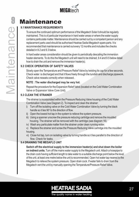
To ensure the continued optimum performance of the Megatech Solar it should be regularlymaintained. This is of particular importance in hard water areas or where the water supplycontains particulate matter. Maintenance should be carried out by a competent person and anyreplacement parts used should be authorised Heatrae Sadia Megatech spare parts. It isrecommended that maintenance is carried out every 12 months and includes the checksdetailed in 9.2 and 9.3 below.In hard water areas consideration should be given to periodically descaling the immersionheater elements. To do this the Megatech unit will need to be drained, 9.4 and 9.5 below detailhow to drain the unit and remove the immersion heater(s).
9.2 CHECK OPERATION OF SAFETY VALVESSlowly open the Temperature and Pressure Relief Valve by twisting its cap for a few seconds.Check water is discharged and that it flows freely through the tundish and discharge pipework.Check valve reseats correctly when released.NOTE : The water discharged may be very hot.Repeat the procedure for the Expansion Relief Valve (located on the Cold Water CombinationValve or Expansion Valve Core Unit).
9.3 CLEAN THE STRAINERThe strainer is incorporated within the Pressure Reducing Valve housing of the Cold WaterCombination Valve (see Diagram 2). To inspect and clean the strainer:i) Turn off the isolating valve on the Cold Water Combination Valve by turning the black
handle so it lies 90o to the direction of flow.ii) Open the lowest hot tap in the system to relieve the system pressure.iii) Using a spanner unscrew the pressure reducing cartridge and remove the moulded housing. The strainer will be removed with the cartridge (see diagram 16).iv) Wash any particulate matter from the strainer under clean running water.v) Replace the strainer and screw the Pressure Reducing Valve cartridge into the mouldedhousing.vi) Close hot tap, turn on isolating valve by turning handle so it lies parallel to the direction of flow. Check for leaks.
9.4 DRAINING THE MEGAFLO UNITSwitch off the electrical supply to the immersion heater(s) and shut down the boileron indirect units. Turn off the mains water supply to the Megatech unit. Attach a hosepipe tothe drain cock having sufficient length to take water to a suitable discharge point below the levelof the unit, at least one metre below the unit is recommended. Open hot water tap nearest to theMegatech to relieve the system pressure. Open drain cock. If water fails to drain from theMegatech vent the unit by manually opening the Temperature/Pressure Relief Valve.
9 Maintenance
2828
techtech
9.5 DESCALING IMMERSION HEATER(S)Isolate the electrical supply before removing covers and drain unit of water. Open the cover(s) to theimmersion heater housing(s) and disconnect wiring from immersion heater(s). Remove the thermostatby carefully pulling outwards from the immersion heater. Unscrew immersion heater backnut(s) andremove immersion heater from the unit. A key spanner is supplied with the Megatech unit for easyremoval/tightening of the immersion heater(s). Over time the immersion heater gasket may becomestuck to the mating surface. To break the seal insert a round bladed screwdriver into one of the pocketson the immersion heater and gently lever up and down.Carefully remove any scale from the surface of the element(s). DO NOT use a sharp implement asdamage to the element surface could be caused. Ensure sealing surfaces are clean and seals areundamaged, if in doubt fit a new gasket.Replace immersion heater(s) ensuring the lower (right angled) element hangs vertically downwardstowards the base of the unit. It may be helpful to support the immersion heater using a round bladedscrewdriver inserted into one of the thermostat pockets whilst the backnut is tightened. Replace thethermostat(s) by carefully plugging the two male spade terminations on the underside of the thermostathead into the corresponding terminations on the element.Rewire the immersion heater(s) in accordance with Diagram 10. Close and secure terminal cover(s).
9.6 EXPANSION VESSEL CHARGE PRESSURERemove the dust cap from the top of the expansion vessel. Check the charge pressure using a tyrepressure gauge. The charge pressure (with the system de-pressurised) should be 0.3 MPa (3 bar). Ifit is lower than the required setting it should be re-charged using a tyre pump (Schrader valve type).DO NOT OVER CHARGE. Re-check the pressure and when correct replace the dust cap.
9.7 REFILLING SYSTEMDO NOT SWITCH ON THE IMMERSION HEATER(S) OR BOILER UNTIL THE SYSTEMHAS BEEN COMPLETELY REFILLED.Close the drain tap. With hot tap open, turn on mains water supply. When water flows from the hottap allow to flow for a short while to purge air and to flush through any disturbed particles. Close hottap and then open successive hot taps in system to purge any air. The electrical supply can now beswitched on.
9.8 BENCHMARKTM LOG BOOKOn completion of any maintenance or service of the Megatech Solar the BenchmarkTM “Installation,Commissioning and Service Record Log Book” should be filled in to record the actions taken and thedate the work was undertaken.
Mai
nten
ance

����
���
��
29
techFa
ult F
indi
ng &
Ser
vici
ng10.1 IMPORTANT
i) Servicing should only be carried by authorised Heatrae Sadia Service Engineers or Agentsor by competent installers in the installation and maintenance of unvented water heatingsystems.
ii) Any spare parts used MUST be authorised Heatrae Sadia parts.iii) Disconnect the electrical supply before removing any electrical equipment covers.iv) NEVER bypass any thermal controls or operate system without the necessary safety
valves.v) Water contained in the Megatech Solar unit may be very hot, especially following a thermal
control failure. Caution must be taken when drawing water from the unit.
10.2 SPARE PARTSA full range of spare parts are available for the Megatech Solar range. Refer to the Technical Datalabel on the unit to identify the model installed and ensure the correct part is ordered.Description Part no.Immersion heater (lower) 95 606 963Immersion heater (upper) 95 606 964Immersion heater gasket 95 611 822Immersion heater backnut 95 607 869Immersion heater key 95 607 861Solar temperature probe pocket plate 95 607 064Tundish 95 605 838Expansion relief valve cartridge - 8bar 95 605 870Expansion Valve complete 95 607 028Cold water combination valve body incl. isolating valve 95 605 029Check valve housing 95 605 028Pressure reducing valve cartridge - 3bar 95 605 026Pressure reducing valve housing 95 605 027Cold Water Combination Valve complete 95 605 021Temperature/Pressure Relief Valve 95 605 810Expansion Core Unit 95 605 041Expansion Vessel (25 litre) 95 607 612Swept Tee 95 605 812Set of compression nuts and olives 95 607 838Combined thermostat/thermal cut-out (immersion heater) 95 612 026Terminal cover (Direct units) 95 607 8362 Port motorised valve (Indirect (CL) units only) 95 605 819Indirect thermostat 95 612 697Indirect thermal cut-out 95 612 698Terminal cover (Indirect (CL) units only) 95 607 8374 way terminal block (Indirect (CL) units only) 95 607 902Accessory kit indirect 95 607 093Accessory kit direct 95 607 095Insulation set T&P relief valve 95 607 089Drain valve 1/4 turn 95 605 051Wiring centre 95 607 008
10 Fault Finding & Servicing

3030
techtechFa
ult F
indi
ng &
Ser
vici
ng
10.3 FAULT FINDINGThe Fault Finding chart overleaf (Table 2) will enable operational faults to be identified and their possiblecauses rectified. Any work carried out on the Megatech Solar unvented water heater and its associatedcontrols MUST be carried out by a competent installer for unvented water heating systems. In case ofdoubt contact the Heatrae Sadia Service Department (see Section 13).
Valve Body95 605 029
Check Valve Housing95 605 028
Pressure ReducingValve Housing
95 605 027
Pressure ReducingValve Cartridge (3 bar)
95 605 026
Cold Water CombinationValve Complete
95 605 021Strainer Mesh
Housing SecuringScrews (4 off )
Compression Nutsand Olives
Expansion Cartridge95 605 870
Expansion Valve(body only)95 607 028
Expansion Core Unit(brass tee only -
incorporatescheck valve)
95 605 041
Diagram 16 - Exploded view of the Cold Water Combination Valve and ExpansionCore Unit

����
���
��
31
tech
Table 2 - Fault Finding ChartF AU L T P O S S IB L E C AU S E R E M E D YNo hot water flow 1. M ains s upply off 1. Chec k and open s top c oc k
2. S trainer bloc k ed 2. Turn off water s upply . Rem ove s trainer and c lean (s ee S ec tion 9.3)
3. Cold W ater Com bination V alve inc orrec t ly fit ted
3. Chec k and refit as required
W ater from hot taps is c old
1. DIRE CT im m ers ion heater not s witc hed on
1. Chec k and s witc h on
2. DIRE CT im m ers ion heater therm al c ut-out has operated
2. Chec k . Res et by pus hing but ton. (S ee Diagram 11)
3. INDIRE CT program m er s et to Central Heating only
3. Chec k . S et to a Dom es tic Hot W ater program m e
4. INDIRE CT boiler not work ing
4. Chec k boiler operation. If fault is s us pec ted c ons ult boiler m anufac turer's ins truc t ions
5. INDIRE CT therm al c ut-out has operated
5. Chec k . Res et by pus hing but ton on c ut-out. Chec k operation of indirec t therm os tat (s ee D iagram 13)
6. INDIRE CT m otoris ed valve not c onnec ted c orrec tly
6. Chec k w iring and/or plum bing c onnec t ions to m otoris ed valve (s ee D iagram s 14 & 15)
7. S O LA R ins uffic ient s olar gain w ith no aux iliary heating s w itc hed on
7. Chec k aux iliary heat s ourc e is s w itc hed on and is c ontrolled to provide heat gain if no s olar output is available.
W ater dis c harges 1. INTE RM ITTE NTLYfrom E x pans ion Relief V alve
E x pans ion volum e has reduc ed within E x pans ion V es s el
1. S ee S ec tion 9.6 for re-c harging proc edure
2. CO NTINUA LLYa. Cold W ater Com bination V alve P res s ure Reduc er not work ing c orrec tly
a. Chec k pres s ure from Cold W ater Com binat ion V alve. If greater than 3 bar replac e P res s ure Reduc er c art ridge
b. E x pans ion V alve s eat dam aged.
b. Rem ove E x pans ion V alve c artridge. Chec k c ondit ion of s eat . If nec es s ary fit new E x pans ion V alve c art ridge.
W ater dis c harges from T& P Relief V alve
1. Therm al c ontrol fa ilure NO TE water w ill be very hot
1. S witc h off power to im m ers ion heater(s ), s hut down boiler and s olar prim ary c irc uit . DO NO T turn off water s upply . W hen dis c harge s tops c hec k all therm al c ontrols , replac e if faulty .

3232
techtechD
imen
sion
s &
Spe
cific
atio
ns11 Dimensions & Specifications
Diagram 17 - DimensionsDirect units
Indirect units
370
433 41
2
29A B D
E
5
62
1
3
7
4
F 20˚25˚ 30˚
1 SOLAR PRIMARY RETURN2 SOLAR PRIMARY FLOW3 T&P VALVE 4 BOOST IMMERSION HEATER5 AUXILLARY IMMERSION HEATER6 INLET7 SOLAR CONTROL HOUSING
Ø
594
550
45˚
81
370
433 41
2
29A B C D
E
7
82
1
3
4
5
9
6
F 20˚25˚ 30˚
1 SOLAR PRIMARY RETURN2 SOLAR PRIMARY FLOW3 AUXILLARY BOILER RETURN4 AUXILLARY BOILER FLOW5 T&P VALVE 6 SECONDARY RETURN 7 AUXILLARY CONTROL HOUSING8 INLET9 SOLAR CONTROL HOUSING
Ø
594
550
45˚
81

����
���
��
33
tech
Table 3 - Dimensions
Table 4 - Direct units - Technical specifications
Table 5 - Indirect units - Technical specifications
NOTECoil heating performance based on a primary flow rate of 15 l/min at 80o C.Temperature rise is from 15o C to 60o C.Heating times using the solar primary circuit will depend on the amount of solar radiation,sunshine hours, collector panel type, size and orientation so will be variable.
A B C D E F190 Direct 1372 950 - 740 - 1019190 Indirect 1372 - 732 803 923 1019210 Direct 1473 1000 - 759 - 1184210 Indirect 1473 - 892 808 1095 1184250 Direct 1731 1072 - 773 - 1391250 Indirect 1731 - 1160 883 1258 1391300 Direct 2038 1409 - 870 - 1715300 Indirect 2038 - 1438 1023 1573 1715
DIMENSIONS (mm)SIZE TYPE
EMPTY FULL LOWER (3kW) UPPER + LOWER (6kW)
UPPER BOOST (3kW)
190 40.5 230.5 124 122 61 60210 42.5 252.5 141 150 75 60250 51.5 301.5 175 183 92 60300 61.5 361.5 210 220 110 60
UNIT WEIGHT (kg) HEAT UP TIMES (mins)SIZE AUXILLARY
VOLUME (L)
EMPTY FULL SURFACE (sq.m)
HEAT UP (mins)
RECOVERY (mins)
RATING (kW)
190 45.5 235.5 127 0.61 19 14.5 18.0210 47.5 257.5 147 0.68 24 18.5 18.0250 56.5 306.5 175 0.73 26 20 18.7300 66.5 366.5 210 0.79 25 19 24.5
AUXILLARY COIL SPECIFICATIONSUNIT WEIGHT (kg)SIZE AUXILLARY
VOLUME (L)

3434
techtech
OUTLINE SPECIFICATIONS
Maximum mains water supply pressure (to Cold Water Combination Valve) 1.6 MPa (16 bar)
Operating pressure (Pressure reducing valve set pressure - non adjustable) 0.3 MPa (3 bar)
Expansion relief valve set pressure 0.8 MPa (8 bar)
Temperature/Pressure relief valve set temp/pressure 90oC/ 1 MPa (10 bar)
Immersion heater rating (a.c. supply only) 3.0kW 240V2.7kW 230V
Outer casing:White textured plastic coated corrosion proofed steel
Water container:Duplex stainless steel (grade 1.4362 to EN10088). 100% pressure tested to 1.5 MPa (15 bar).
Thermal insulation:CFC/HCFC free fire retardant expanded polyurethane foam with zero ozone depletion potential. It has aGlobal Warming Potential (GWP) of 3.1. Nominal thickness 50mm.
Pipe connections:All connections accept 22mm outside diameter pipe - compression nuts and olives supplied. Thread rate is3/4” BSP male parallel to accept standard 3/4”BSP female fittings if required.
Safety features:Direct units -
Manually resettable thermal cut-out on each heating elementFactory fitted Temperature/Pressure relief valve
Indirect units -Manually resettable thermal cut-out on heating elementManually resettable thermal cut-out for primary heating. Must be wired in conjunction with 2-port motorised valve supplied.Factory fitted Temperature/Pressure relief valve
Dim
ensi
ons
& S
peci
ficat
ions

����
���
��
35
techG
uara
ntee
12.1 WARNINGShould the factory fitted Temperature and Pressure Relief Valve be tampered with or removedyour guarantee will be invalidated. Neither the Distributor or Manufacturer shall be responsiblefor any consequential damage howsoever caused.
12.2 GUARANTEE TERMSHeatrae Sadia guarantee the electrical parts, thermal controls and valves for a period of twoyears, excluding the cold water control valve which is guaranteed for a period of five years,from the date of purchase, with the exception of damage due to scaling.The Expansion Vessel is guaranteed for a period of five years.The stainless steel vessel is guaranteed for a period of twenty-five years against faultymanufacture or materials provided that :-i) It has been installed by a competent installer and as per the instructionscontained in this manual and all relevant Codes of Practice and Regulations in force at thetime of installation.ii) Any disinfection has been carried out in accordance with BS 6700.iii) It has not been modified in any way other than by Heatrae Sadia Heating.iv) It has only been used for the storage of wholesome water.v) It has not been installed in a location liable to be subjected to frost, nor has it beentampered with or been subjected to misuse or neglect.vi) No factory fitted parts have been removed for unauthorised repair or replacement.vii) Within 60 days of purchase the user completes and returns the certificate supplied toregister the product.Evidence of purchase and date of supply must be submitted.This guarantee is not valid for installations outside the United Kingdom and the Republic ofIreland. For installations outside these territories please contact either the Heatrae Sadia HeatingExport Department (Tel: +44 1603 420191) or Baxi International (Tel: + 44 1926 478323) forfurther details of the guarantee terms and conditions applicable.This guarantee does not affect your statutory rights.
ENVIRONMENTAL INFORMATIONThis product is made from many recyclable materials, therefore at the end of its useful life itshould be disposed of at a Local Authority Recycling Centre in order to realise the fullenvironmental benefits.Insulation is by means of an approved HCFC/CFC free polyurethane foam.
12 Guarantee
The pace of product development is such that we reserve the right to change product specificationswithout notice. We do, however, strive to ensure that all information in this leaflet is accurate at thetime of publication.

3636
techtechC
onta
cts
13 ContactsSPARES STOCKISTS
Electric Water Heating Co.2 Horsecroft Place, Pinnacles,Harlow, EssexCM19 5BTTel: 0845 0553811E-mail: [email protected]
SPDSpecial Products Division,Units 9 & 10 Hexagon Business Centre,Springfield Road, Hayes, MiddlesexUB4 0TYTel: 020 8573 0574
Parts CenterNetwork 65 Business ParkBentley Wood WayBurnley, LancashireBB11 5STTel: 01282 834403www.partscenter.co.uk
Newey & EyreSpecialist Products DivisionPlease contact your local branch
UK Spares Ltd.Tower Lane, WarmleyBristolBS30 8XTTel: 0117 961 6670
William Wilson Ltd.Unit 3A, 780 South Street,Whiteinch, GlasgowG14 0SYTel: 0141 434 1530
CUSTOMER SERVICETel: 0844 8711535Fax: 0844 8711528E-mail: heatraesadiaservice
@heateam.co.uk
ADDRESSHeatrae Sadia HeatingHurricane WayNorwichNorfolkNR6 6EA
SWITCHBOARDTel: 01603 420100