Guide to Power System Selective Coordination and Below 0100DB0603
Meeting the NEC®
Selective CoordinationRequirements
Robert E. Fuhr, P.E.
PowerStudies, Inc.
Maple Valley, WA.

� NEC® is a trademark of the National Fire Protection Association, Inc.
Agenda
� Definitions
� NEC Code Requirements
� Fuse Selective Coordination
� Breaker Trip Unit Types
� Breaker Selective Coordination
� Procedure to Achieve Selective Coordination
– Fuses
– Breakers
� Arc Flash and Selective Coordination
� Examples

Special Thanks
� Square D Company
� Data Bulletin
� “Enhancing Short Circuit Selective Coordination with Low Voltage Breakers”
� http://ecatalog.squared.com/pubs/Circuit%20Protection/0100DB0403.pdf

Special Thanks
� Cooper Bussmann
� White paper & SPD p21
– Traces the Codeology for Selective Coordination Requirements
� Papers and Online Voiceover Training Module
� www.CooperBussmann.com

NFPA 70 and NFPA 70E
How you built it. How you work on it.
Primarily Fire Protection Primarily Personnel Protection
NEC® 2011
� Chapters 1 through 4:
– Generally for all electrical installations
– No selective coordination requirements
� Selective coordination requirements under “special” Chapters
� Chapter 7 Special Conditions
– Emergency Systems: 700.27
– Legally Required Standby Systems: 701.27
– Critical Operations Power Systems: 708.54
�NEC® is a trademark of the National Fire Protection Association, Inc.
Selective Coordination Requirements 2011 NEC®
� Chapter 5 Special Occupancies
� Healthcare Facilities: 517.26 - Essential Electrical Systems
� These special systems supply vital loads essential for life safety, public safety, or national security.
� Reliability more crucial than for systems in Chapter 1-4.
These Special System Requirements
� Separate dedicated Articles in the NEC
– 700, 701, 708, & 517
� Minimum standards
– Delivering reliable power to life safety loads

These Special System Requirements
� Alternate power sources
� Separate wiring
� Locate wiring to avoid outage due to physical damage
� Testing, maintenance, and record retention
� Automatic transfer switches (ATSs)
� Separate ATSs for load segmenting & shedding

12
Selective Coordination in the NEC
� 100 Definition: Coordination Selective (2005)
� 517.26 Required for Essential Electrical Systems (2005)
� 620.62 Required for Circuits with multiple Elevators (1993)
� 695.3(C)(3) Power Sources for Fire Pumps in Multi-building Campus Style Complexes (2011)
13
Selective Coordination in the NEC
� 700.27 Required for Emergency Systems (2005)
� 701.27 Required for Legally Required Standby Systems (2005)
� 708.54 Required for Critical Operations Power Systems (COPS) (2008)
517.2 Definitions
� Emergency System.
– A system of circuits and equipment intended to supply alternate power to a limited number of prescribed functions vital to the protection of life and safety.
– Essential for safety of human life.
� NEC® 700.2 Informational Note:
– Emergency systems are generally installed in places of assembly where artificial illumination is required for safe exiting and for panic control in buildings subject to occupancy by large numbers of persons....,
– such as hotels, theaters, sports arenas, health care facilities, and similar institutions. Emergency systems may also provide power for such functions as ventilation where essential to maintain life, fire detection and alarm systems, elevators, fire pumps, public safety communications systems, industrial processes where current interruption would produce serious life safety or health hazards, and similar functions.”

Emergency Backup Power

ARTICLE 100 Definitions
� Coordination (Selective).
– Localization of an overcurrent condition to restrict outages to the circuit or equipment affected, accomplished by the choice of overcurrent protective devices and their ratings or settings.
240.12 Electrical System Coordination
� Where an orderly shutdown is required to minimize the hazard(s) to personnel and equipment, a system of coordination based on the following two conditions shall be permitted:
– (1) Coordinated short-circuit protection
– (2) Overload indication based on monitoring systems or devices
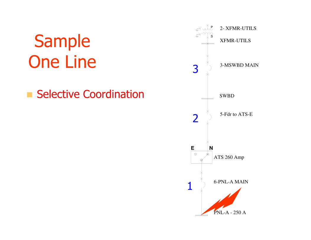
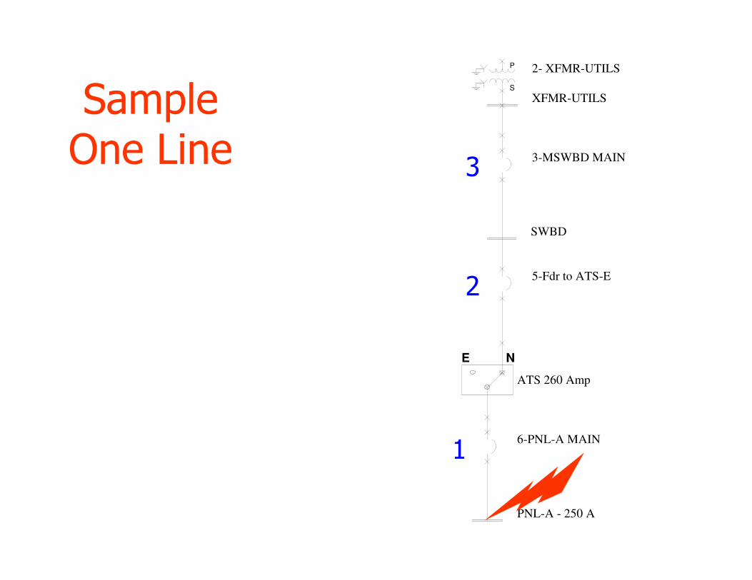
Sample One Line
� Selective Coordination
3-MSWBD MAIN
SWBD
XFMR-UTILSS
P 2- XFMR-UTILS
5-Fdr to ATS-E
6-PNL-A MAIN
PNL-A - 250 A
E N
ATS 260 Amp
1
2
3

3-MSWBD MAIN
SWBD
XFMR-UTILSS
P 2- XFMR-UTILS
5-Fdr to ATS-E
6-PNL-A MAIN
PNL-A - 250 A
E N
ATS 260 Amp
1
1
1
Sample One Line
� No Selective Coordination
701.2 Definitions
� Legally Required Standby Systems.
– Those systems required and so classed as legally required standby by municipal, state, federal, or other codes or by any governmental agency having jurisdiction.
– These systems are intended to automatically supply power to selected loads (other than those classed as emergency systems) in the event of failure of the normal source.
701.2 Definitions
� Informational Note:– Legally required standby systems are typically installed to serve loads, such as heating and refrigeration systems, communications systems, ventilation and smoke removal systems, sewage disposal, lighting systems, and industrial processes, that, when stopped during any interruption of the normal electrical supply, could create hazards or hamper rescue or fire-fighting operations.
517.2 Health Care Facilities Definitions
� Essential Electrical System. – A system comprised of alternate sources of power and all connected distribution systems and ancillary equipment, designed to ensure continuity of electrical power to designated areas and functions of a health care facility during disruption of normal power sources, and also designed to minimize disruption within the internal wiring system.
517.2 Health Care Facilities Definitions
� Alternate Power Source. – One or more generator sets, or battery systems where permitted, intended to provide power during the interruption of the normal electrical services or the public utility electrical service intended to provide power during interruption of service normally provided by the generating facilities on the premises.
517.2 Health Care Facilities Definitions
� Critical Branch.
– A subsystem of the emergency system consisting of feeders and branch circuits supplying energy to task illumination, special power circuits, and selected receptacles serving areas and functions related to patient care and that are connected to alternate power sources by one or more transfer switches during interruption of normal power source.

517.30 (A) Essential Electrical System
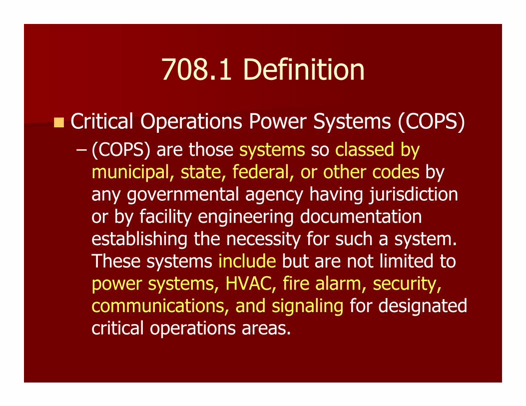
708.1 Definition
� Critical Operations Power Systems (COPS)
– (COPS) are those systems so classed by municipal, state, federal, or other codes by any governmental agency having jurisdiction or by facility engineering documentation establishing the necessity for such a system. These systems include but are not limited to power systems, HVAC, fire alarm, security, communications, and signaling for designated critical operations areas.

708.1 Definition
� Critical Operations Power Systems – Informational Note No. 1: Critical operations power systems are generally installed in vital infrastructure facilities that, if destroyed or incapacitated, would disrupt national security, the economy, public health or safety; and where enhanced electrical infrastructure for continuity of operation has been deemed necessary by governmental authority.”
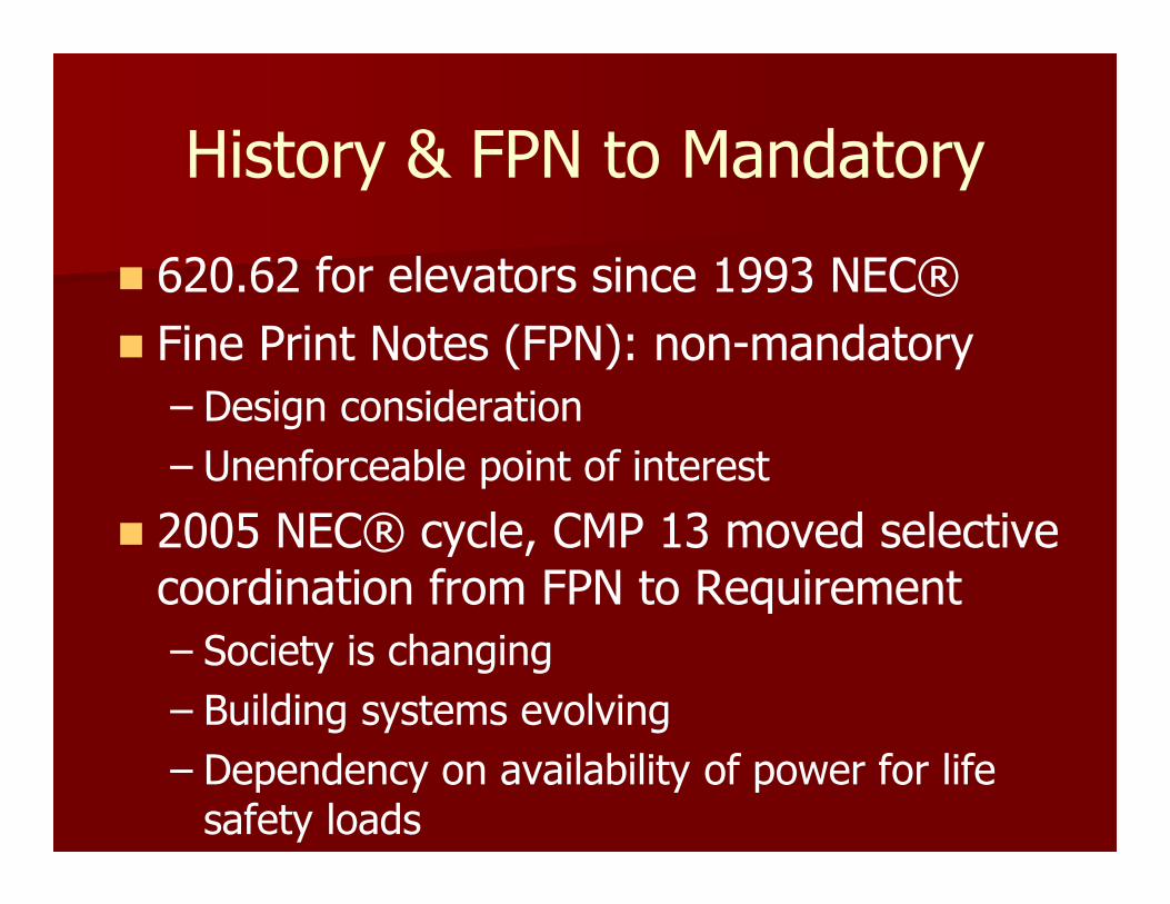
History & FPN to Mandatory
� 620.62 for elevators since 1993 NEC®
� Fine Print Notes (FPN): non-mandatory
– Design consideration
– Unenforceable point of interest
� 2005 NEC® cycle, CMP 13 moved selective coordination from FPN to Requirement
– Society is changing
– Building systems evolving
– Dependency on availability of power for life safety loads

History: FPN to Mandatory
� NEC® Panel 13 Statement:
– “The panel agrees that selective coordination of emergency system overcurrent devices with the supply side overcurrent devices will provide for a more reliable emergency system.”
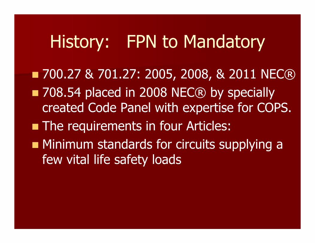
History: FPN to Mandatory
� 700.27 & 701.27: 2005, 2008, & 2011 NEC®
� 708.54 placed in 2008 NEC® by specially created Code Panel with expertise for COPS.
� The requirements in four Articles:
� Minimum standards for circuits supplying a few vital life safety loads

33
The substantiation for the original (2005) NEC®
proposal for Section 700.27
“This article specifically mandates that the emergency circuits be separated from the normal circuits as shown in [Section] 700.9(B)
and that the wiring be specifically located to minimize system hazards as shown in [Section] 700.9(C), all of which reduce the probability of faults, or failures to the system so it will be operational when called upon.

34
The substantiation for the original (2005) NEC®
proposal for Section 700.27
With the interaction of this Article for emergency lighting for egress, it is imperative that the lighting system remain operational in an emergency.
Failure of one component must not result in a condition where a means of egress will be in total darkness as shown in [Section] 700.16….
Selectively coordinated overcurrent protective devices will provide a system that will support all these requirements and principles.
35
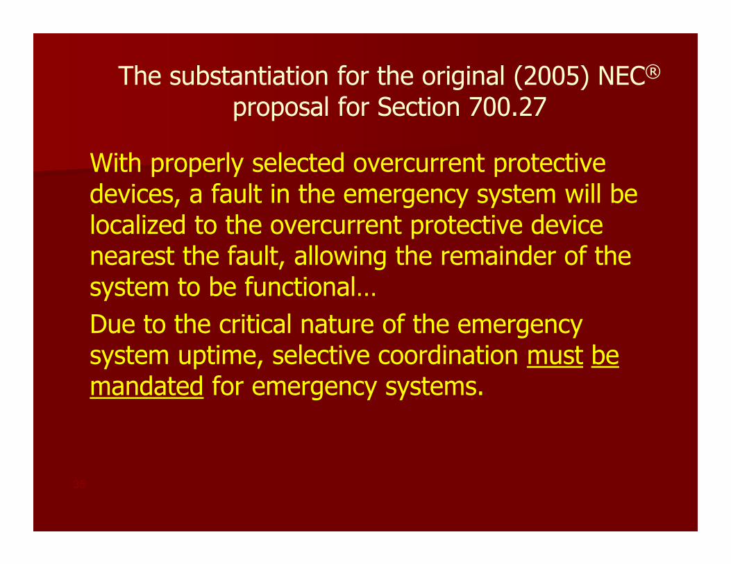
The substantiation for the original (2005) NEC®
proposal for Section 700.27
With properly selected overcurrent protective devices, a fault in the emergency system will be localized to the overcurrent protective device nearest the fault, allowing the remainder of the system to be functional…
Due to the critical nature of the emergency system uptime, selective coordination must bemandated for emergency systems.

Problems with this Code Requirement
– Circuit Breakers
� Most breakers have an instantaneous trip function.
– Fixed
– Adjustable
– For Faults -Breaker trips instantaneously (no time delay)
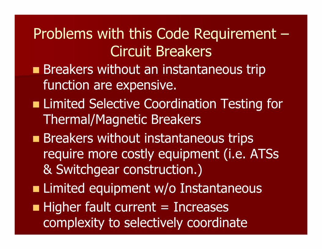
Problems with this Code Requirement –Circuit Breakers
� Breakers without an instantaneous trip function are expensive.
� Limited Selective Coordination Testing for Thermal/Magnetic Breakers
� Breakers without instantaneous trips require more costly equipment (i.e. ATSs & Switchgear construction.)
� Limited equipment w/o Instantaneous
� Higher fault current = Increases complexity to selectively coordinate
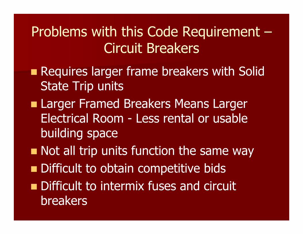
Problems with this Code Requirement –Circuit Breakers
� Requires larger frame breakers with Solid State Trip units
� Larger Framed Breakers Means Larger Electrical Room - Less rental or usable building space
� Not all trip units function the same way
� Difficult to obtain competitive bids
� Difficult to intermix fuses and circuit breakers

Problems with this Code Requirement - Fuses
� Requires larger equipment than using T/M CBs
� Larger Electrical Room – Less rental or usable building space
� Reduces Levels of downstream equipment
� Fusible Panelboards and Elevator Modules are more expensive than T/M circuit breakers
Reality
Very Expensive to Design and Comply

This new Section of the code will radically change the way we all design emergency and standby
power systems.

Real Problem or a Perceived (Paper) Problem?
� On paper, breakers with instantaneous trip units will not coordinate.
� In the real world…is this a problem?
� How many times has this happened at your customers or your facilities?
– Incorrect trip unit settings do not count
– Poor maintenance or defective trip units do not count
� FACT: Majority of faults are lower level line to ground faults.
Real Problem or a Perceived (Paper) Problem?
� It is hard to argue cost versus safety!
44
Real Problem or a Perceived (Paper) Problem?
� For three NEC® cycles, opposition worked to delete or dilute these requirements
– It has radically changed the way emergency and standby electrical systems are designed.
– Sometimes, it is extremely difficult to do!
– For circuit breakers, the higher the available short circuit current (from the utility source) the harder to achieve selective device coordination.
� It can be very expensive to implement!

Why is Selective Device Coordination an Issue? - Ground-Fault Protection
� Code Requires Ground Fault Selective Coordination for Main and Feeders(medical facilities) only.
� Code does not state that Ground Fault Protection Must Coordinate with the Phase Protection.
� Considered a different protection scheme
� Maximum Pickup setting is 1,200 Amperes
� Maximum Time Delay setting is 0.5 sec.
Ground-Fault Protection
� Limited Equipment GF options for fuses
� Many times impossible to prevent overlap with ground fault and phase devices.
� False Sense of Security????
– Ignoring selective device coordination between phase and ground fault devices does not increase reliability.
– Majority of electrical faults are line to ground faults.
More Problems with the Code
� Modifications or additions to a facility.
– How far do you go to implement selective coordination?
– Include the existing and the new equipment?
– See WAC Rules 296-46B-700 & 701

WAC 296-46B-700 Emergency systems
� 027 Coordination
– (4) The requirements for selective coordination described in NEC 700.27 are not required where the emergency system was installed prior to June 1, 2006.
– For new emergency systems that are supplied from an existing emergency system installed prior to June 1, 2006, the new portion of the emergency system must comply with NEC 700.27.
WAC 296-46B-700 Emergency systems
� 027 Coordination
– The ground fault sensing function of overcurrent protective devices will only be required to selectively coordinate with the ground fault sensing functions of other overcurrent protective devices.
WAC 296-46B-701 Legally required standby systems
� 018 Coordination
– Uses the same wording as previous.
More Problems with the Code
� Inconsistent requirements and enforcement through out the US.
– For our customers....AZ, WA, and OR only (so far)
– City of Seattle and some other AHJs allow overlap in the breaker instantaneous region.
– Most AHJs only require selective coordination for emergency supply NOT normal (Utility) Supply

Seattle Electrical Code (SEC)
� Selective coordination as required by Articles 620.62, 700.27, 701.18, and 708.54 has been amended by the SEC.
� Fault current calculations provided by a licensed electrical engineer may be selectively coordinated for faults with a duration of 0.1 seconds or longer.
Seattle Electrical Code (SEC)
� The calculations will be required to be wet stamped by a licensed Washington State electrical engineer.
� All other calculations will be required to be calculated to infinity and will not be permitted to utilize adjustable trip breakers to achieve selective coordination.

More Problems with the Code
� Utility Transformer Sizing
– NEC forces designers to over design a building.
– Actual load 1st year is less than 50% of the design demand.
– Utilities size transformers 30 – 50% of the designers demand load.
– Utility fuse overlaps with downstream mains and feeder breakers.

Resources and Additional Info
� http://www.geindustrial.com/solutions/engineers/selective_coordination.html
� http://www.eaton.com/Electrical/Consultants/SelectiveCoordination/index.htm
� http://www.schneider-electric.us/sites/us/en/customers/consulting-engineer/selective-coordination.page

Resources and Additional Info� http://www.sea.siemens.com/us/Support/Consulting-Engineers/Pages/SelectiveCoordination.aspx
� http://www1.cooperbussmann.com/2/SelectiveCoordination.html
� http://us.ferrazshawmut.com/resources/articles-white-papers.cfm
� http://us.ferrazshawmut.com/resources/online-training.cfm

Summary
� You must change the way you design circuits for:– Emergency
– Standby
– Elevators
– Fire Pumps
� Manufacturers must provide:– New Equipment to meet the code
– Tools (tables, spreadsheets, charts)
– I2T Withstand curves for Equipment
Need more Information
� www.powerstudies.com
– Articles
– Links
– Specifications for Power System Studies
� Short Circuit
� Protective Device Coordination
� Arc Flash Hazard
� Low and High Voltage Electrical Safety Training

Questions??
Thank you for your time!

Meeting the NEC Selective Coordination
Requirements(Afternoon Session)
Robert E. Fuhr, P.E.
PowerStudies, Inc.
Maple Valley, WA.
ARTICLE 620 Elevators, Dumbwaiters, Escalators, Moving Walks, Wheelchair Lifts, and
Stairway Chair Lifts
� 620.62 Selective Coordination.
– Where more than one driving machine disconnecting means is supplied by a single feeder, the overcurrent protective devices in each disconnecting means shall be selectively coordinated with any other supply side overcurrent protective devices.
Emergency Systems
� 700.27 Coordination.
– Emergency system(s) overcurrent devices shall be selectively coordinated with all supply side overcurrent protective devices.
– “The provisions of this article apply to the electrical safety of the installation, operation, and maintenance”
– “Essential for safety of human life”
ARTICLE 701 Legally Required Standby Systems
� 701.18 Coordination.
– Legally required standby system(s) overcurrent devices shall be selectively coordinated with all supply side overcurrent protective devices.

ARTICLE 708.54 Critical Operations Power Systems
� 708.54 Coordination.
– Critical operations power system(s) overcurrent devices shall be selectively coordinated with all supply side overcurrent protective devices.
ARTICLE 517 Health Care Facilities
� Essential Electrical Systems must meet Section 700 (except as amended by 517)
� Implies that Essential Electrical Systems must be selectively coordinated. (700.27 & 701.18)
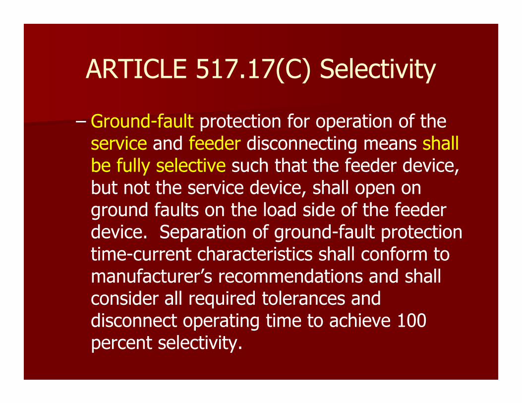
ARTICLE 517.17(C) Selectivity
– Ground-fault protection for operation of the service and feeder disconnecting means shallbe fully selective such that the feeder device, but not the service device, shall open on ground faults on the load side of the feeder device. Separation of ground-fault protection time-current characteristics shall conform to manufacturer’s recommendations and shall consider all required tolerances and disconnect operating time to achieve 100 percent selectivity.
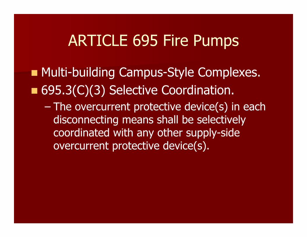
ARTICLE 695 Fire Pumps
� Multi-building Campus-Style Complexes.
� 695.3(C)(3) Selective Coordination.
– The overcurrent protective device(s) in each disconnecting means shall be selectively coordinated with any other supply-side overcurrent protective device(s).

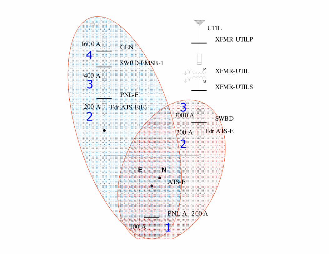
Sample One Line
� Normal Power
� Must be Selectively Coordinated
1
2
3
4
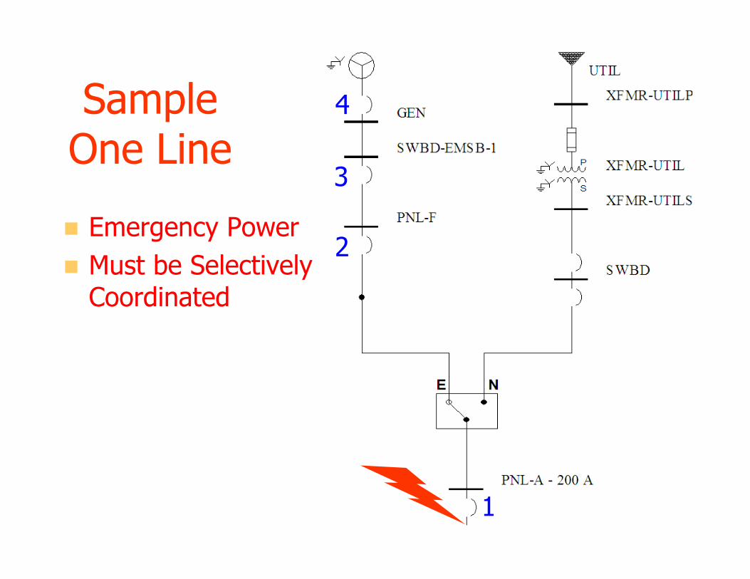
Sample One Line
� Emergency Power
� Must be Selectively Coordinated
1
2
3
4

Definitions
� MCCB – Molded Case Circuit Breaker
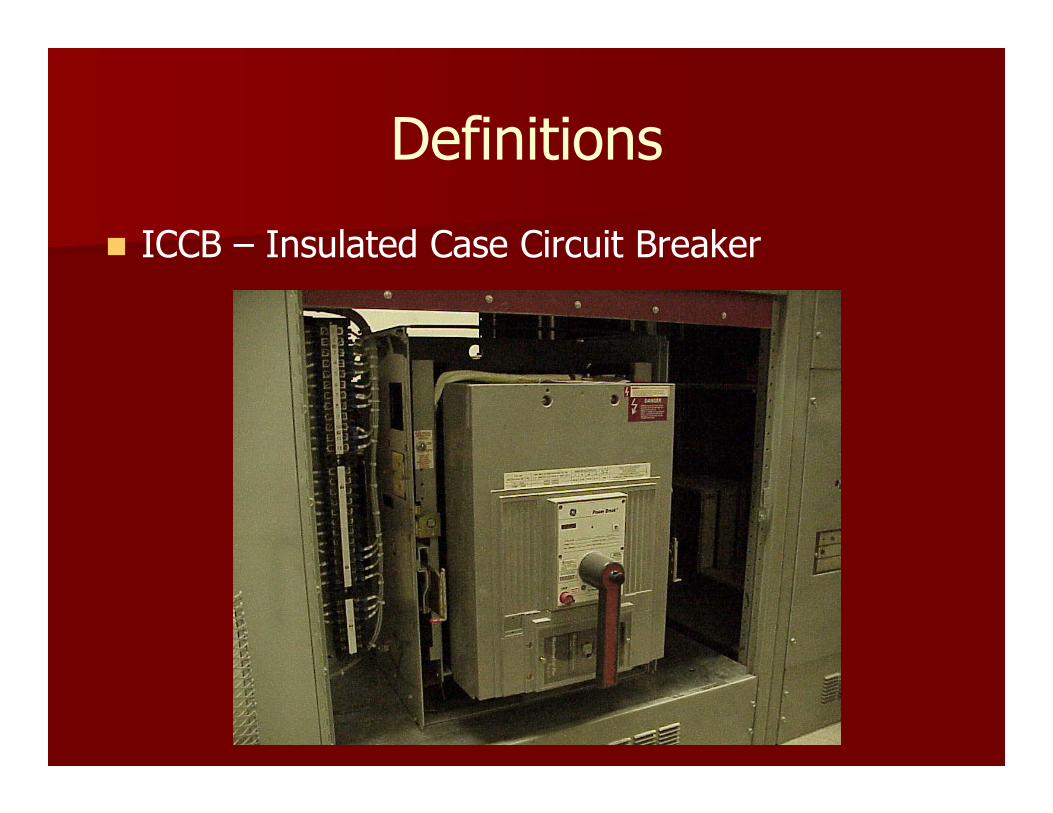
Definitions
� ICCB – Insulated Case Circuit Breaker

Definitions
� LVPCB –Low Voltage Power Circuit Breaker
Time Current Curves
� Time Current Curve (TCC)
� The log-log graph of time versus current.
� Each breaker, fuse, and relay has a time current characteristic curve
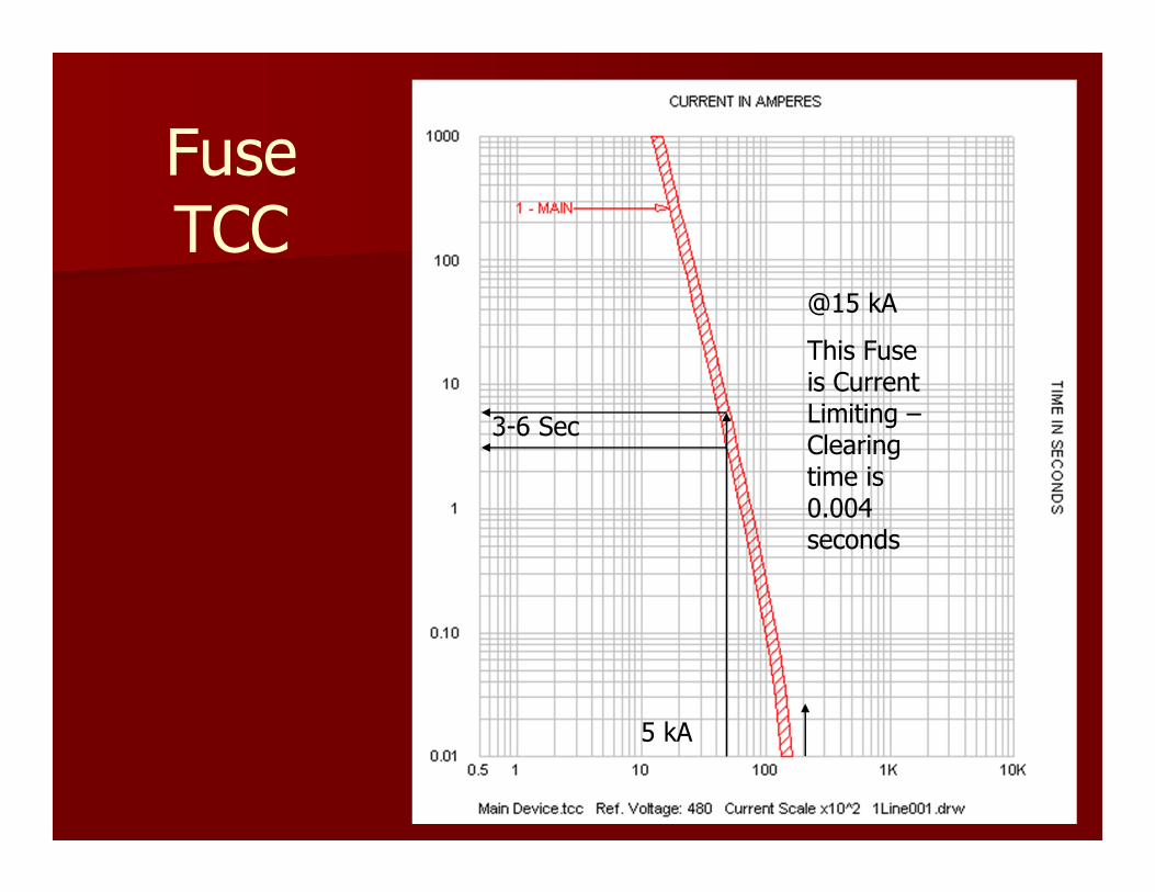
Fuse TCC
3-6 Sec
5 kA
@15 kA
This Fuse is Current Limiting –Clearing time is 0.004 seconds
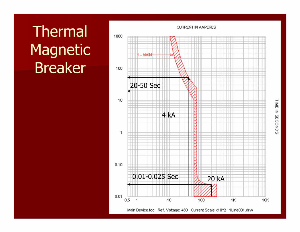
Thermal Magnetic Breaker
20 kA0.01-0.025 Sec
4 kA
20-50 Sec

Solid State Trip
� SQ D NW 40H
� 4000 Amp
� Micrologic
100 kA
0.01-0.06 Sec
6 kA
0.08-0.12 Sec 30 kA
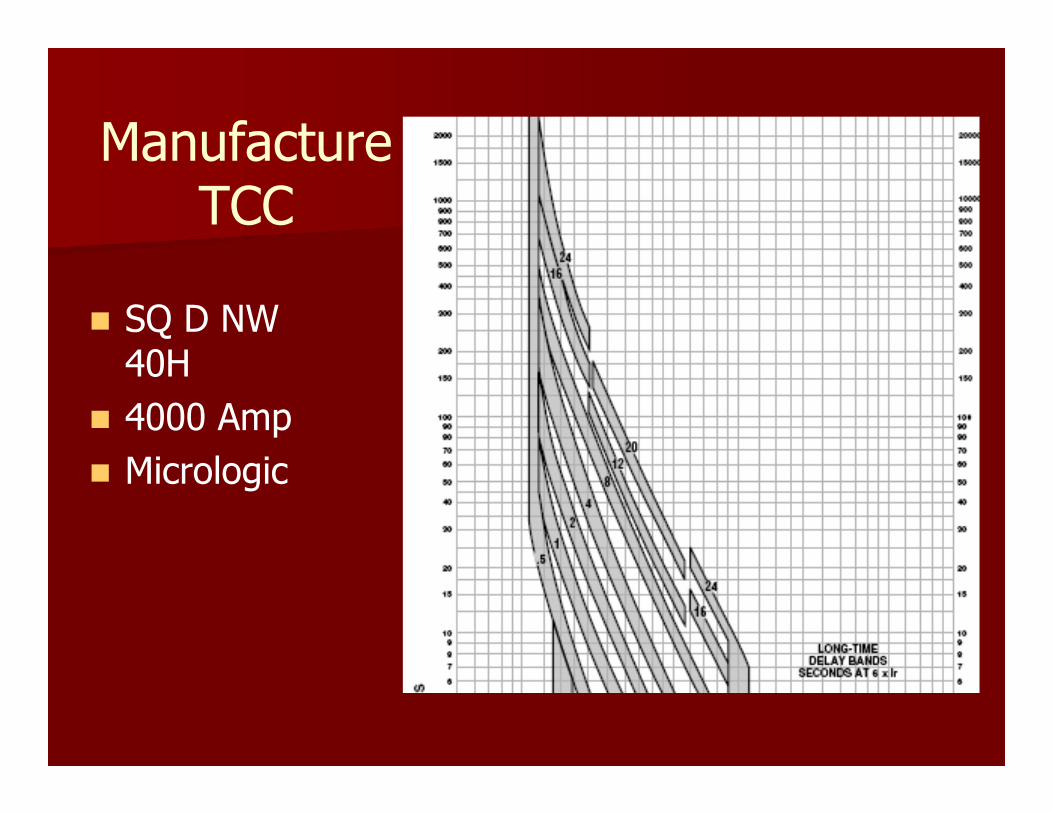
170-210 Sec
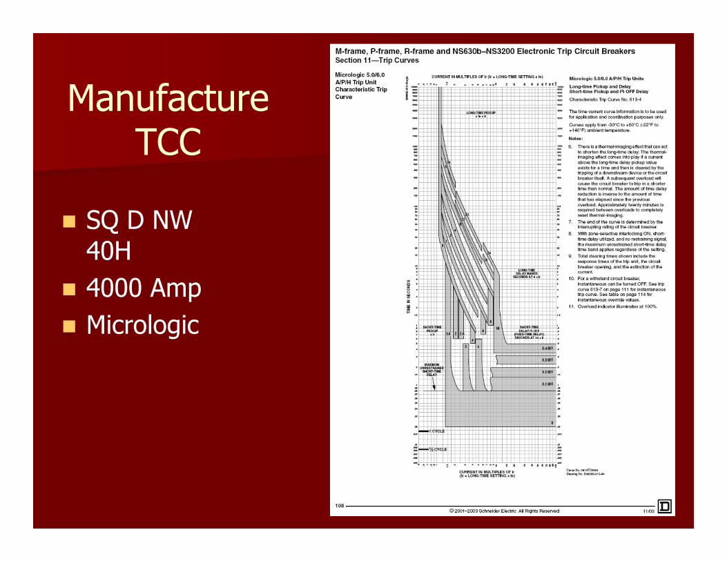
Manufacture TCC
� SQ D NW 40H
� 4000 Amp
� Micrologic
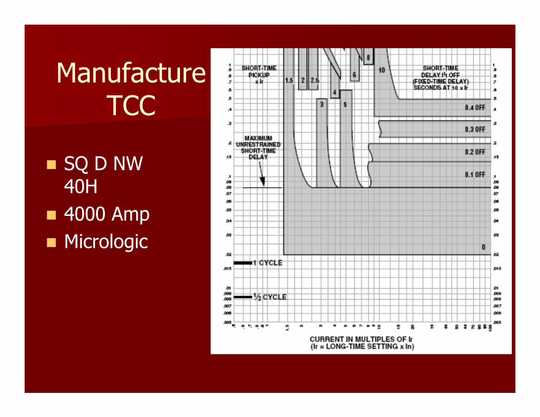
Manufacture TCC
� SQ D NW 40H
� 4000 Amp
� Micrologic
Manufacture TCC
� SQ D NW 40H
� 4000 Amp
� Micrologic

What is Selective Device Coordination
� Devices closest to the fault must operate first.
� Upstream devices trip in sequence
� No overlap on TCCs
Sample One Line 3-MSWBD MAIN
SWBD
XFMR-UTILSS
P 2- XFMR-UTILS
5-Fdr to ATS-E
6-PNL-A MAIN
PNL-A - 250 A
E N
ATS 260 Amp
1
2
3

Selective Coordination Breakers
� Three Breakers in Series
� No Overlap
� Easy Right?
100 A
200 A
3000 A
UTIL
XFMR-UTILP
S
P XFMR-UTIL
XFMR-UTILS
SWBD
GEN
SWBD-EMSB-1
PNL-F
E N
ATS-E
PNL-A - 200 A
Fdr ATS-E
Fdr ATS-E(E)200 A
400 A
1600 A
1
2
3
1
2
3
4
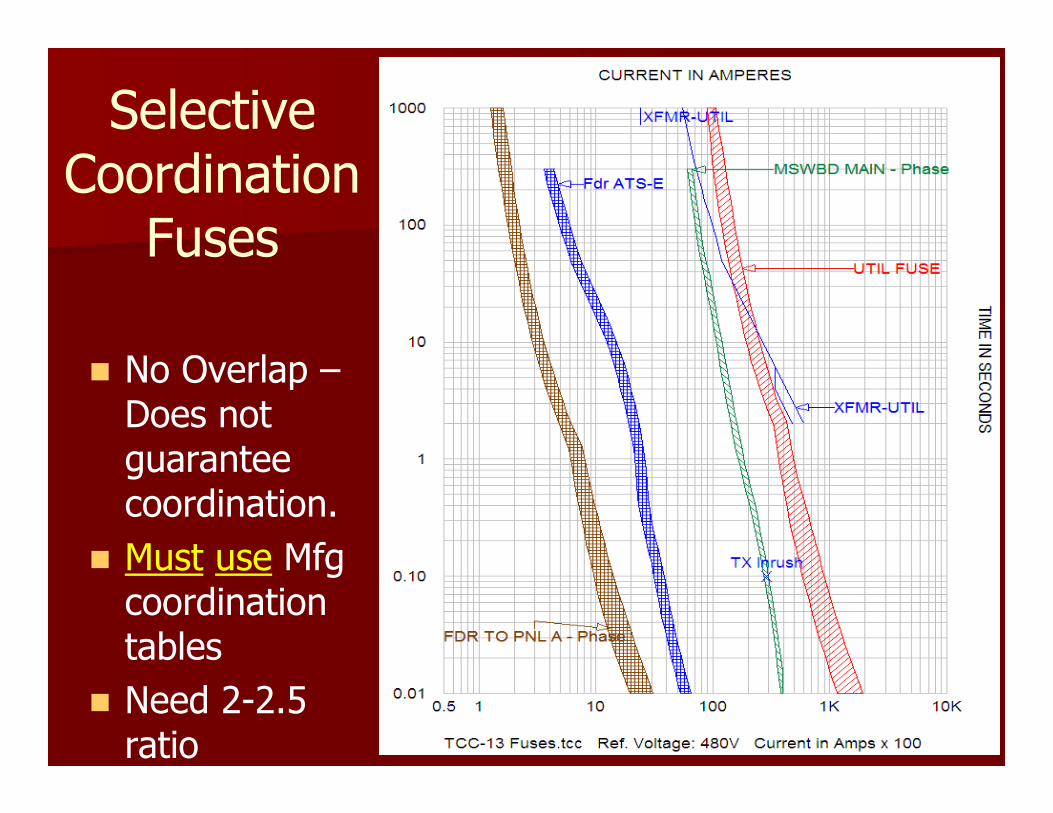
Selective Coordination
Fuses
� No Overlap –Does not guarantee coordination.
� Must use Mfg coordination tables
� Need 2-2.5 ratio
Problems with this Code Requirement - Fuses
� Requires larger equipment than using T/M CBs
� Larger Electrical Room – Less rental or usable building space
� Reduces Levels of downstream equipment
� Fusible Panelboards and Elevator Modules are more expensive than T/M circuit breakers
Problems with this Code Requirement –Circuit Breakers
� Most breakers have an instantaneous trip function.
– Breaker trips instantaneously (no time delay)
� No Selective Coordination Testing for Thermal/Magnetic Breakers
� Limited equipment w/o Instantaneous
� Higher fault current = Increases complexity to selectively coordinate
Problems with this Code Requirement –Circuit Breakers
� Requires larger frame breakers with Solid State Trip units
� Larger Framed Breakers Means Larger Electrical Room - Less rental or usable building space
� Not all trip units function the same way
� Difficult to obtain competitive bids

Reality
Very Expensive to Design and Comply
This new Section of the code will radically change the way we all design emergency and standby
power systems.

Real Problem or a Perceived (Paper) Problem?
� On paper, breakers with instantaneous trip units will not coordinate.
� In the real world…is this a problem?
� How many times has this happened to your customer’s or your facility?
– Before you answer the question....
– Incorrect trip unit settings do not count
– Poor maintenance or defective trip units do not count

Selective Coordination - Fuses
� Fuses have been tested for coordination.
� Relatively easy to select equipment to coordinate.
� Pick Fuses from Manufacturer’s Fuse Selective Coordination Charts
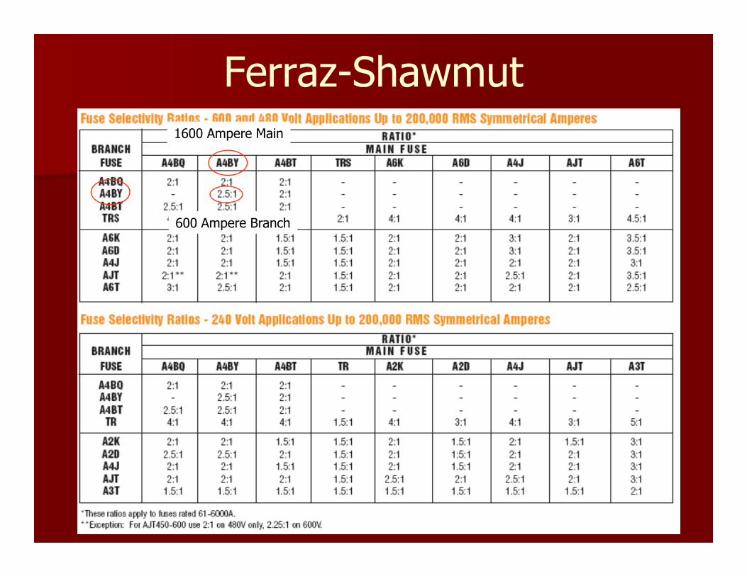
Ferraz-Shawmut
1600 Ampere Main
600 Ampere Branch
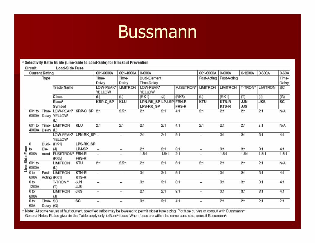
Bussmann
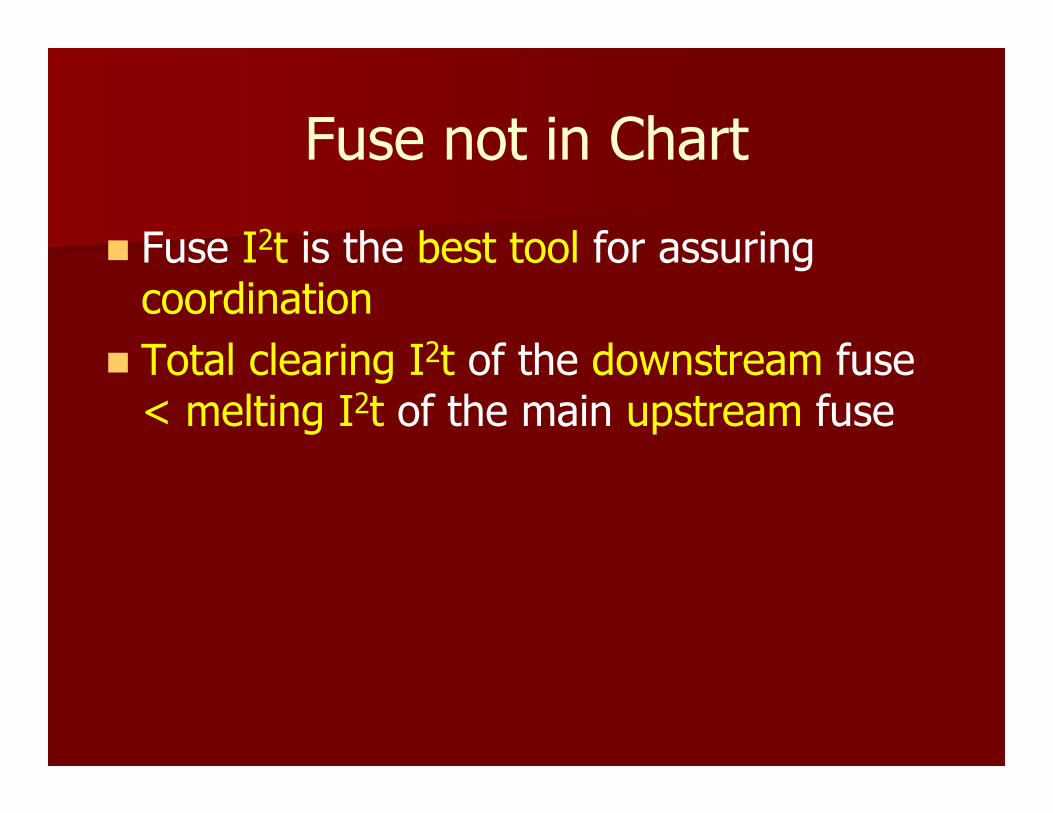
Fuse not in Chart
� Fuse I2t is the best tool for assuring coordination
� Total clearing I2t of the downstream fuse < melting I2t of the main upstream fuse
Selective Coordination – Fuses
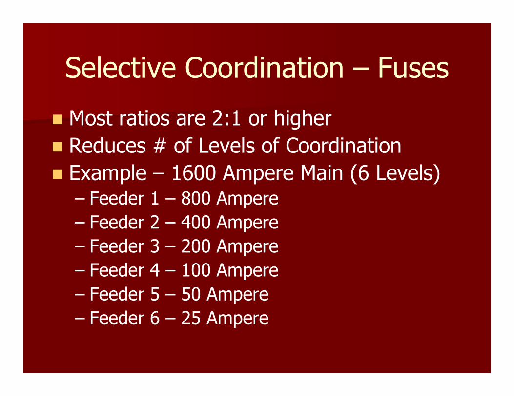
� Most ratios are 2:1 or higher
� Reduces # of Levels of Coordination
� Example – 1600 Ampere Main (6 Levels)– Feeder 1 – 800 Ampere
– Feeder 2 – 400 Ampere
– Feeder 3 – 200 Ampere
– Feeder 4 – 100 Ampere
– Feeder 5 – 50 Ampere
– Feeder 6 – 25 Ampere
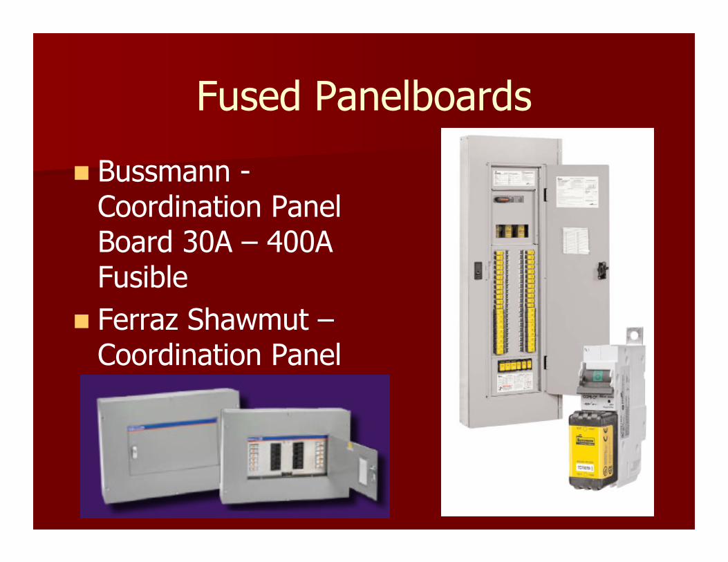
Fused Panelboards
� Bussmann -Coordination Panel Board 30A – 400A Fusible
� Ferraz Shawmut –Coordination Panel
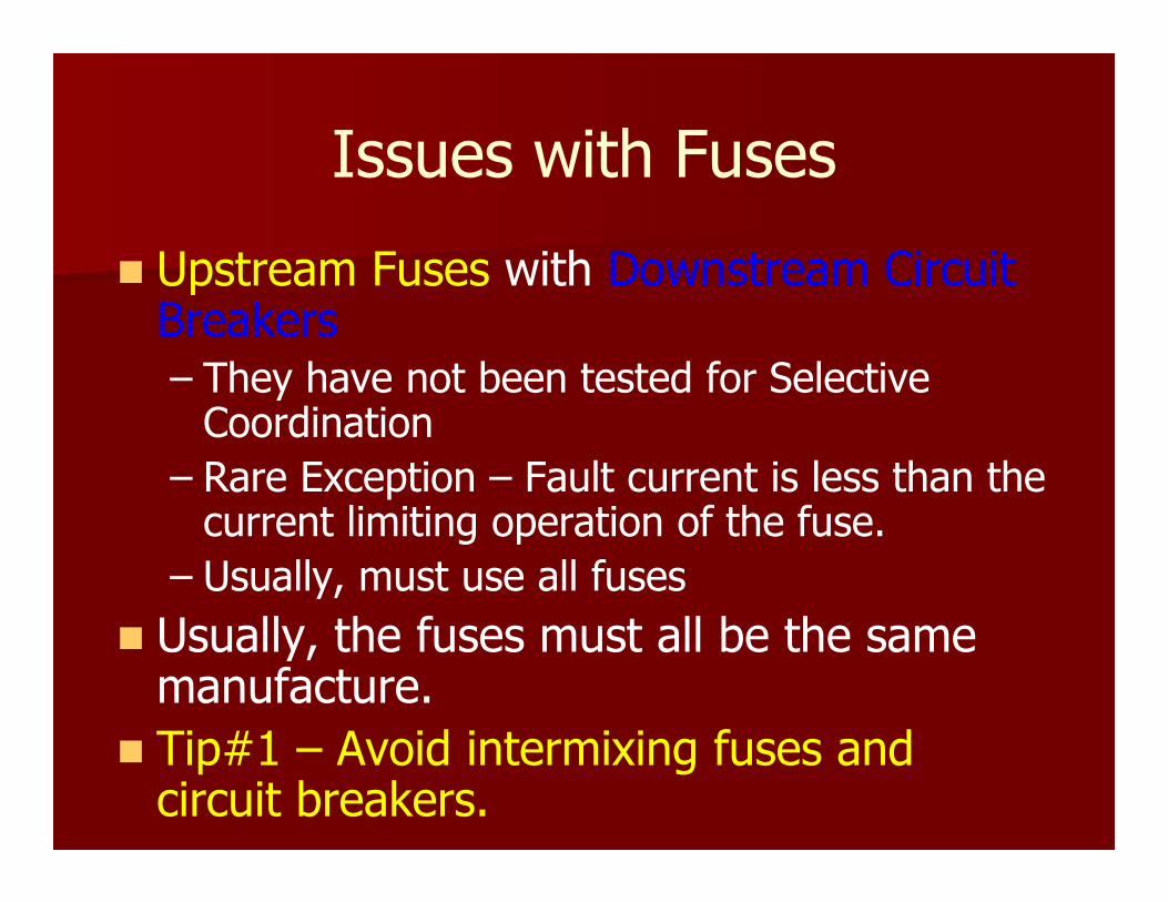
Issues with Fuses
� Upstream Fuses with Downstream Circuit Breakers– They have not been tested for Selective Coordination
– Rare Exception – Fault current is less than the current limiting operation of the fuse.
– Usually, must use all fuses
� Usually, the fuses must all be the same manufacture.
� Tip#1 – Avoid intermixing fuses and circuit breakers.

Circuit Breaker Trip Units
� Thermal Magnetic
� Solid State
– LI (Long Time & Instantaneous)
– LSI (Long, Short Times & Instantaneous)
– LS (Long Time and Short Time)
– G (Ground Fault)
� Not all Solid State Trip Units are alike!!!

Thermal Magnetic Trip Unit
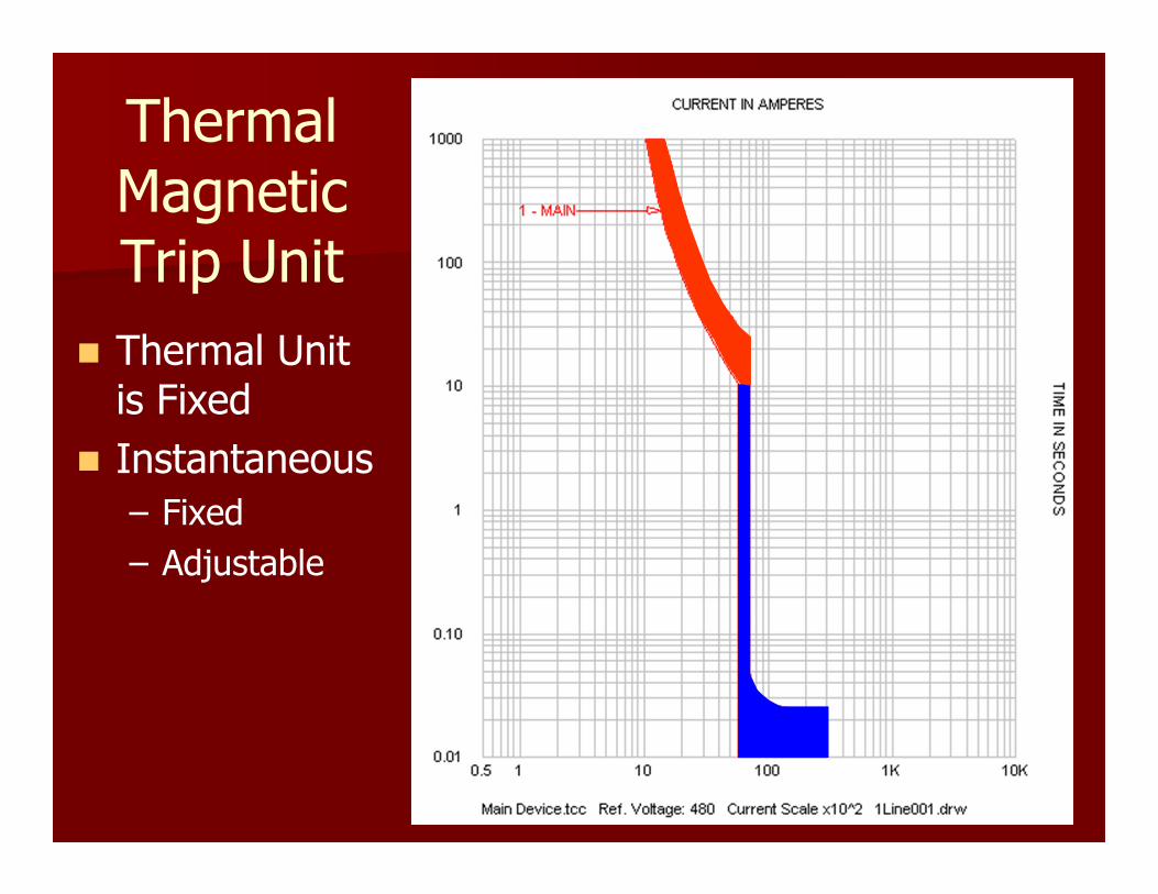
Thermal Magnetic Trip Unit
� Thermal Unit is Fixed
� Instantaneous
– Fixed
– Adjustable

Solid State Trip
Unit
� Varies for each Trip Unit!
� Some Functions are Not Adjustable!
Long Time Pickup (LTPU)
Long Time Delay (LTD)
Short Time Pickup (STPU)
Short Time Delay (STD)
Instantaneous (I)
Short Time
Delay I2T-IN
(I2T)

Solid State Trip
Unit
� SQ D NW 40H
� 4000 Amp
� Micrologic
Current Sensors
Rating Plugs
Current Setting
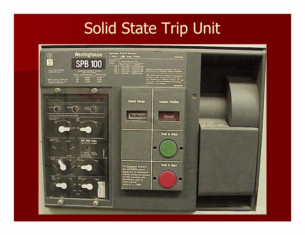
Solid State Trip Unit
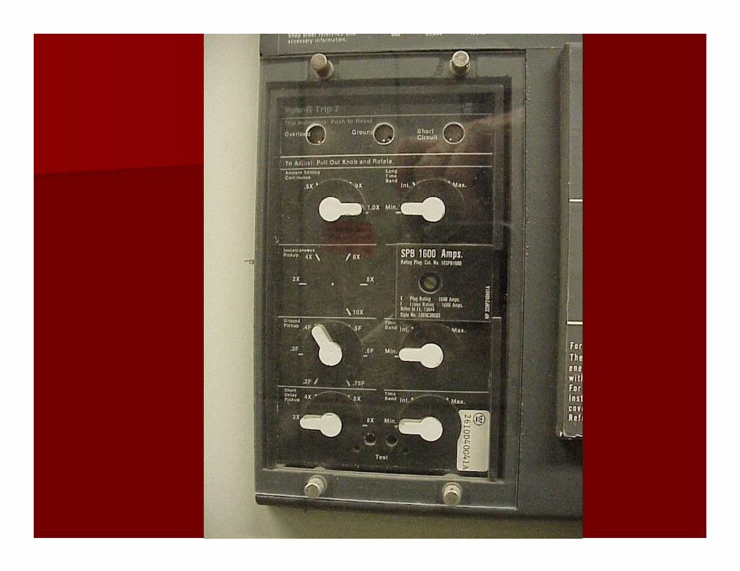
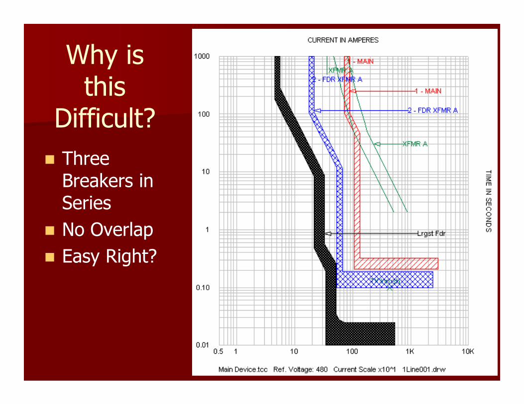
Why is this
Difficult?
� Three Breakers in Series
� No Overlap
� Easy Right?

Why is this
Difficult?� SWBD Main
– SS w/ LI
� Feeder
– SS w/ LSI
� Panel Main
– T/M
� Panel Branch
– T/M
3-MSWBD MAIN
SQUARE D NW40H Sensor/Trip 4000 A
SWBD
480 V
XFMR-UTILS
480 V
S
P 2- XFMR-UTILS
5-Fdr to ATS-E
SQUARE D LE Sensor/Trip 250 APlug 250 A
6-PNL-A MAIN
SQUARE D LA Sensor/Trip 250 A
PNL-A - 250 A
480 V
E N
ATS 260 Amp
12-Lrgst Fdr
SQUARE D FH Sensor/Trip 100 A
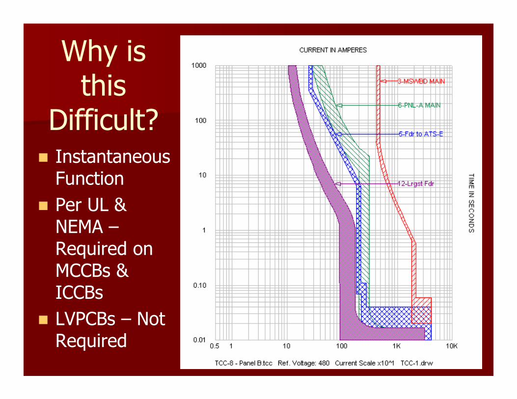
Why is this
Difficult?� Instantaneous Function
� Per UL & NEMA –Required on MCCBs & ICCBs
� LVPCBs – Not Required
Solution
� Eliminate the Instantaneous Function by:
– Reducing the fault current
� Transformers
� Reactors
� Long Conductor Lengths
– Setting Instantaneous above fault current.
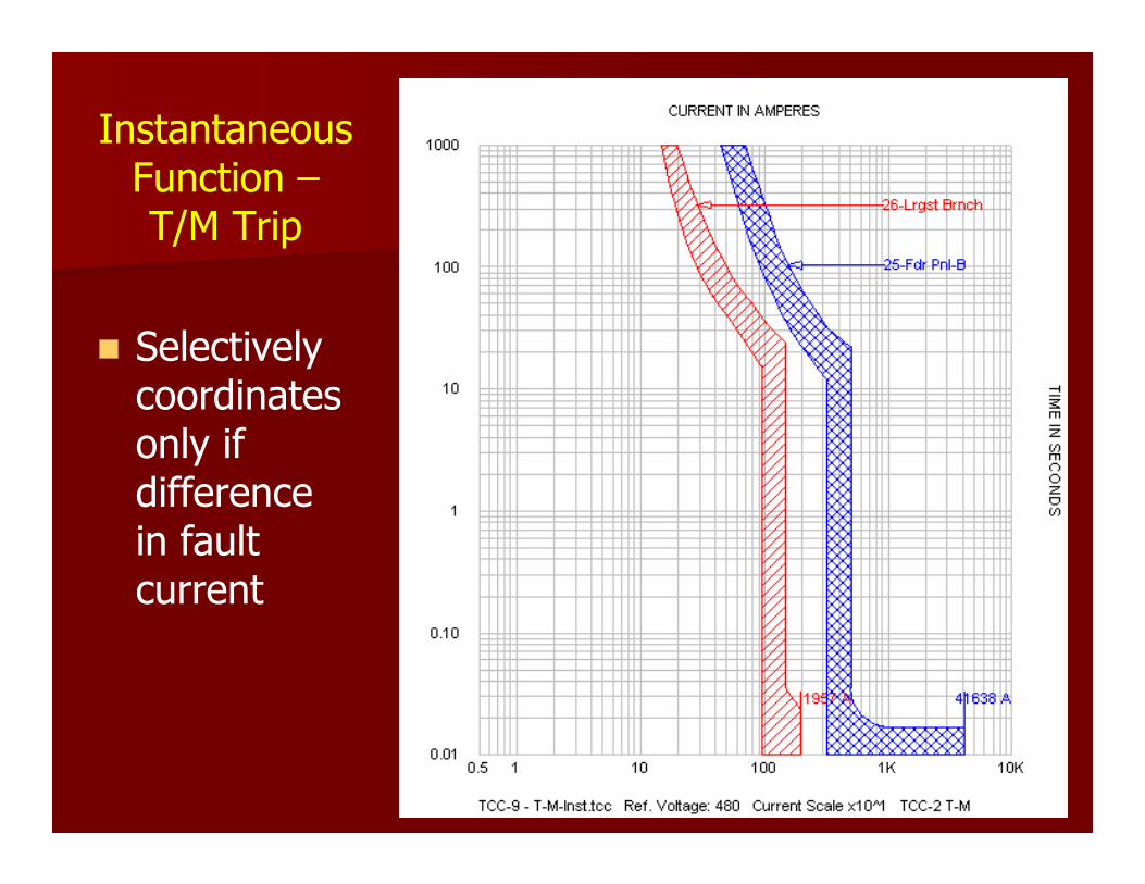
Instantaneous Function –T/M Trip
� Selectively coordinates only if difference in fault current
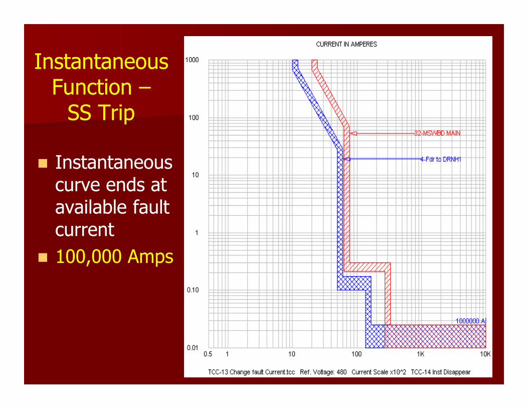
InstantaneousFunction –SS Trip
� Instantaneous curve ends at available fault current
� 100,000 Amps
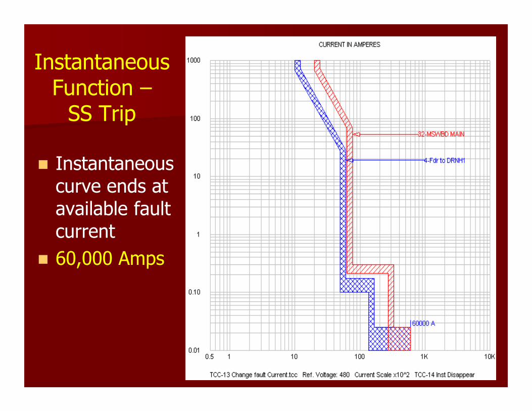
InstantaneousFunction –SS Trip
� Instantaneous curve ends at available fault current
� 60,000 Amps
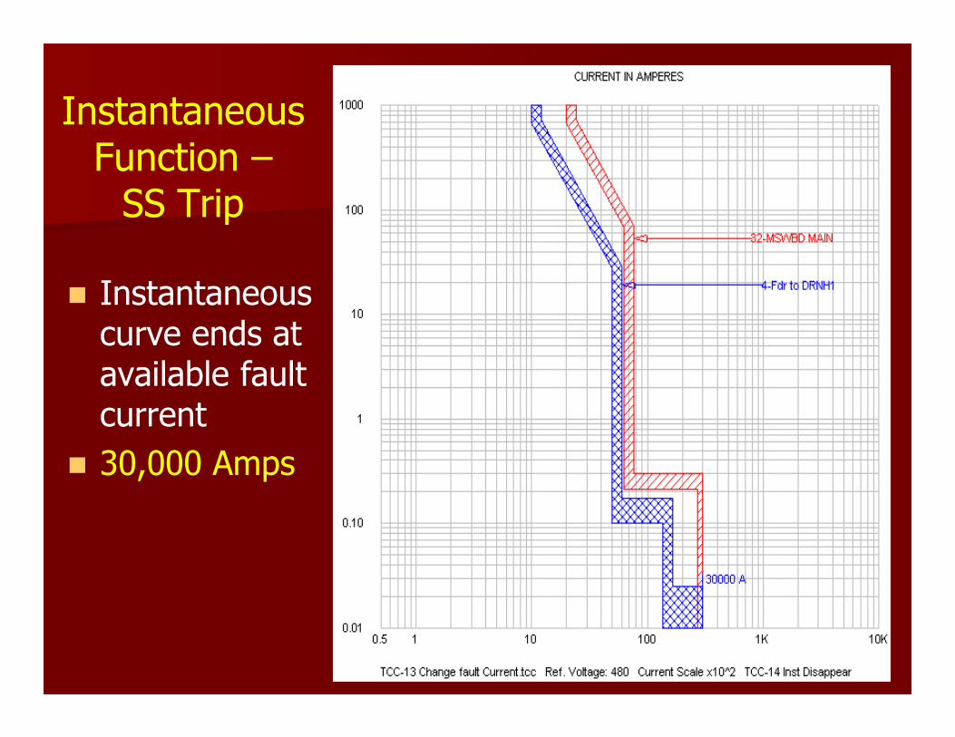
InstantaneousFunction –SS Trip
� Instantaneous curve ends at available fault current
� 30,000 Amps
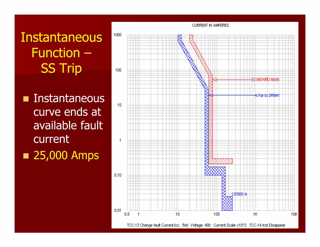
InstantaneousFunction –SS Trip
� Instantaneous curve ends at available fault current
� 25,000 Amps

InstantaneousFunction –SS Trip
� Instantaneous curve ends at available fault current
� 15,000 Amps
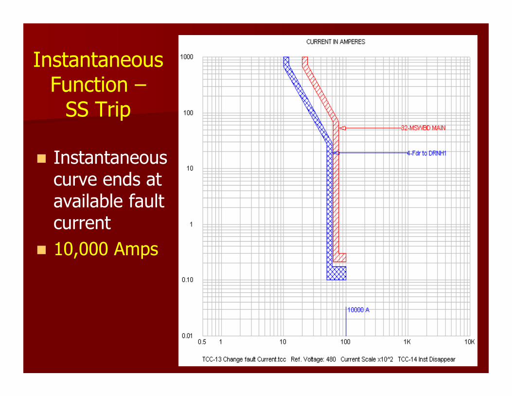
InstantaneousFunction –SS Trip
� Instantaneous curve ends at available fault current
� 10,000 Amps

InstantaneousFunction –SS Trip
� Adjust Instantaneous curve above the available fault current
� 3X

InstantaneousFunction –SS Trip
� Adjust Instantaneous curve above the available fault current
� 4X

InstantaneousFunction –SS Trip
� Adjust Instantaneous curve above the available fault current
� 6X
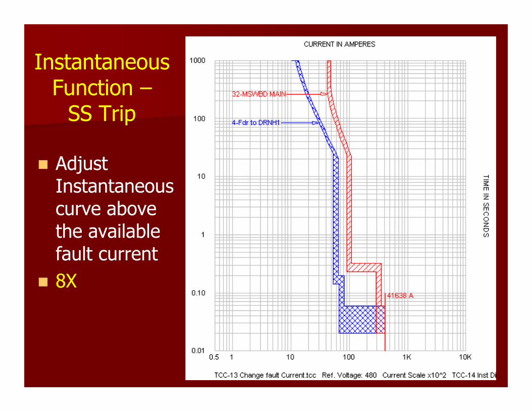
InstantaneousFunction –SS Trip
� Adjust Instantaneous curve above the available fault current
� 8X

InstantaneousFunction –SS Trip
� Adjust Instantaneous curve above the available fault current
� 10X
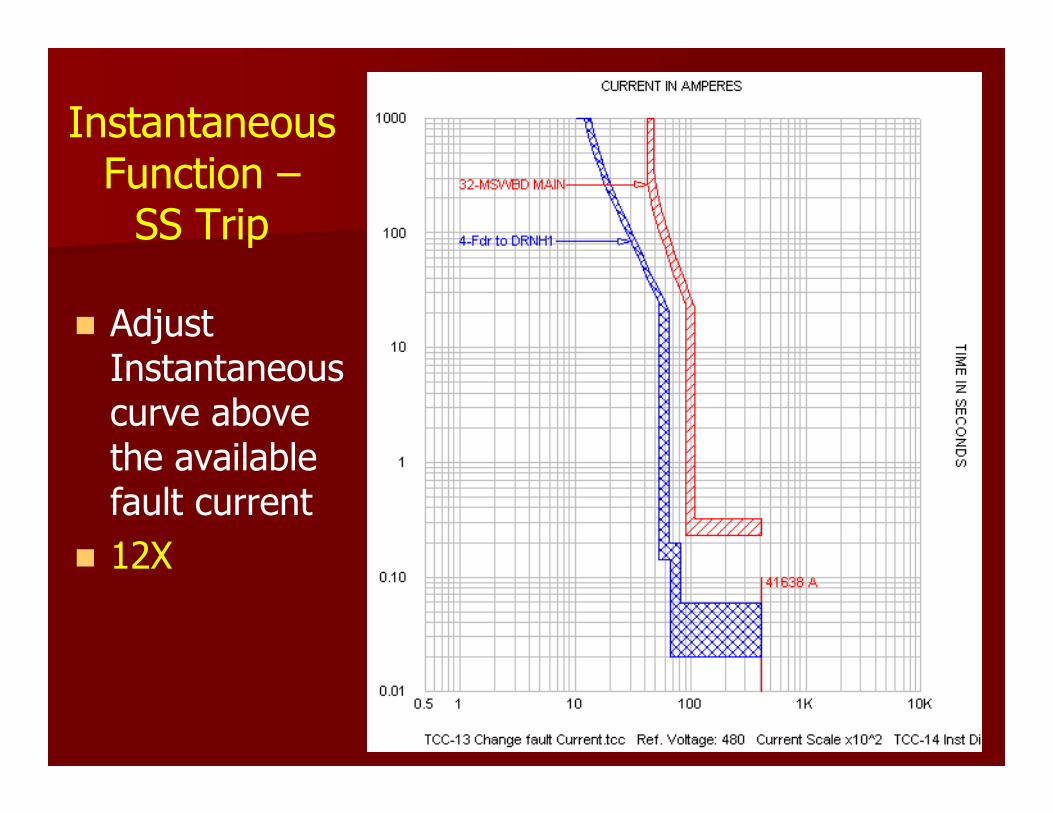
InstantaneousFunction –SS Trip
� Adjust Instantaneous curve above the available fault current
� 12X
Problem – Large Equipment
� Switchboard Feeder and Panelboard Mains many times are ICCB
� Tip #2 – Eliminate Main Breakers in Panelboards.

Switchgear & Switchboard
� Switchgear and switchboard, Panelboard structures are built and tested to different standards:
Switchgear
� ANSI standard C37.20.1
� UL standard 1558
� NEMA standard SG-5
� Switchgear uses power circuit breakers (PCB)
– ANSI C37.13
– NEMA SG-3
– UL-1066
� Unfused switchgear short circuit tested 30 cycles
Switchgear
Instantaneous trip function not required for LVPCBs.
Switchboards
� Group Mounted
� Switchboards Standards
– NEMA PB-2
– UL-891.
� Switchboards may use a combination of protective devices

Switchboards – Devices to Use
� Insulated case (ICCB)
� Molded-case circuit breakers (MCCB)
� Fusible switches
� Power circuit breakers
Group-mounted Switchboards, –Short Circuit Testing
� Short Circuit tested for only 3 cycles
� Protective devices must have instantaneous for UL 891 label
� This Instantaneous trip function reducesselectivity between the main and feedercircuits breakers.
Compartmented Switchboards
� Short Circuit tested for 30 cycles.
� UL 891 Listed
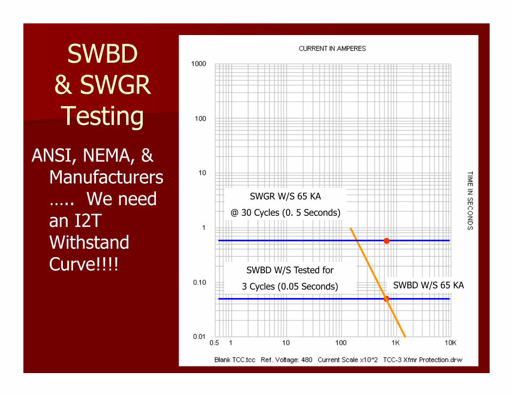
SWBD& SWGR Testing
ANSI, NEMA, & Manufacturers….. We need an I2T Withstand Curve!!!! SWBD W/S Tested for
3 Cycles (0.05 Seconds)
SWGR W/S 65 KA
@ 30 Cycles (0. 5 Seconds)
SWBD W/S 65 KA
More Tips
� Tip #3
– T/M breakers must have a 3:1 ratio to selectively coordinate.
� Tip #4
– Impedance aids in selective coordination
– Long feeder lengths
– Air core reactors
– Transformers
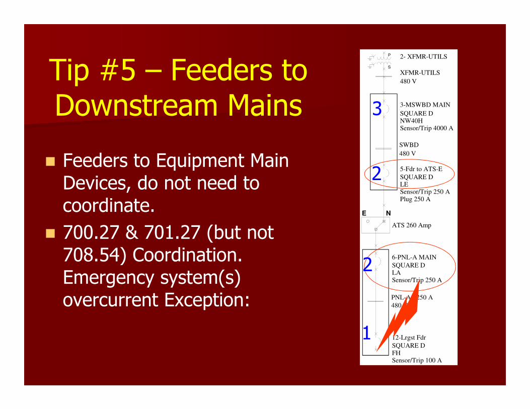
Tip #5 – Feeders to Downstream Mains
� Feeders to Equipment Main Devices, do not need to coordinate.
� 700.27 & 701.27 (but not 708.54) Coordination. Emergency system(s) overcurrent Exception:
3-MSWBD MAIN
SQUARE D NW40H Sensor/Trip 4000 A
SWBD
480 V
XFMR-UTILS
480 V
S
P 2- XFMR-UTILS
5-Fdr to ATS-E
SQUARE D LE Sensor/Trip 250 APlug 250 A
6-PNL-A MAIN
SQUARE D LA Sensor/Trip 250 A
PNL-A - 250 A
480 V
E N
ATS 260 Amp
12-Lrgst Fdr
SQUARE D FH Sensor/Trip 100 A
1
2
2
3
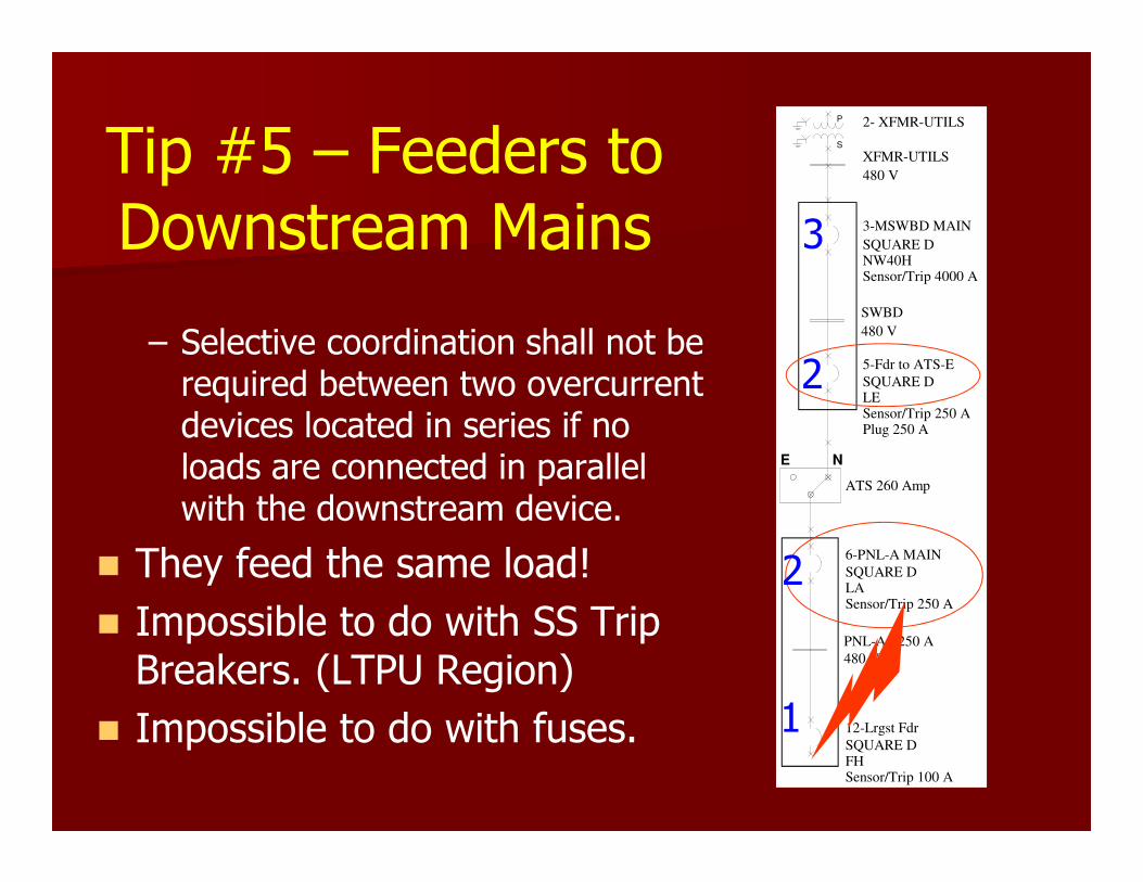
Tip #5 – Feeders to Downstream Mains
– Selective coordination shall not be required between two overcurrent devices located in series if no loads are connected in parallel with the downstream device.
� They feed the same load!
� Impossible to do with SS Trip Breakers. (LTPU Region)
� Impossible to do with fuses.
3-MSWBD MAIN
SQUARE D NW40H Sensor/Trip 4000 A
SWBD
480 V
XFMR-UTILS
480 V
S
P 2- XFMR-UTILS
5-Fdr to ATS-E
SQUARE D LE Sensor/Trip 250 APlug 250 A
6-PNL-A MAIN
SQUARE D LA Sensor/Trip 250 A
PNL-A - 250 A
480 V
E N
ATS 260 Amp
12-Lrgst Fdr
SQUARE D FH Sensor/Trip 100 A
1
2
2
3
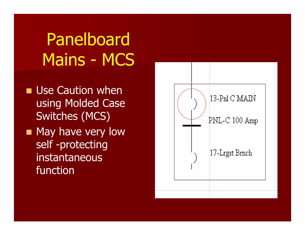
Panelboard Mains - MCS
� Use Caution when using Molded Case Switches (MCS)
� May have very low self -protecting instantaneous function

Transformer Protection
� NEC Table 450.3(B) Maximum Rating or Setting of Overcurrent Protection for Transformers
� Delta-Wye LV Transformers require– Primary Protection @ < 250% rating
– Secondary Protection @ < 125%* rating
– *Use next highest standard rating allowed (see Table 240.6)
� Tip #6 – Keep Table 240.6 within reach
S
P T-3
T-3 PRIM
T-3 SEC
12-Lrgst Brnch
PNL-A - 250 A
13-Pnl C MAIN
PNL-C
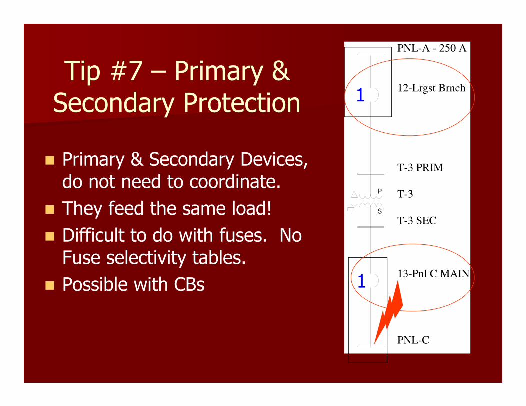
Tip #7 – Primary & Secondary Protection
� Primary & Secondary Devices, do not need to coordinate.
� They feed the same load!
� Difficult to do with fuses. No Fuse selectivity tables.
� Possible with CBs 1
1

More Tips
� Tip #8* - Use SS Trips with LSI(0ff) or Fixed Instantaneous Override
� Tip #9* – Specify that SS Trip Units have adjustable:– LTPU / LTD
– STPU / STD / I2T
– INST(OFF) or Instantaneous Override (above 110% fault current at downstream device)
* - Do not forget the generator breaker

Elevator Selective Coordination
� Elevator Circuits must be selectively coordinated.

ELEV-2
CB-ELEV-2
23-ELEV ST
22-FDR ELEV-2
PNL-A - 250 A
ELEV-2 MOTOR
Tip #10 – Elevator Circuit Coordination
� Feeder and Shunt Trip Devices, do not need to coordinate.
� They feed the same load!
� Impossible to do with fuses if fuses are same size.
� Impossible with CBs
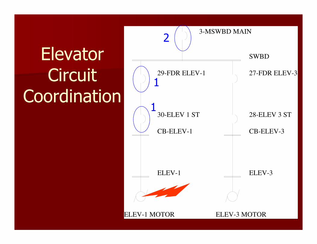
Elevator Circuit
Coordination
ELEV-1 ELEV-3
CB-ELEV-3CB-ELEV-1
SWBD
3-MSWBD MAIN
ELEV-1 MOTOR ELEV-3 MOTOR
28-ELEV 3 ST
27-FDR ELEV-3
30-ELEV 1 ST
29-FDR ELEV-1
1
1
2
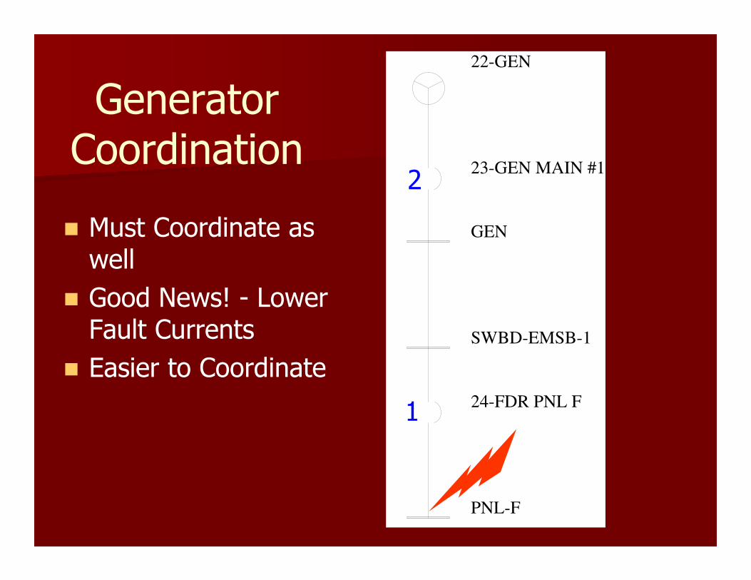
22-GEN
23-GEN MAIN #1
GEN
SWBD-EMSB-1
24-FDR PNL F
PNL-F
Generator Coordination
� Must Coordinate as well
� Good News! - Lower Fault Currents
� Easier to Coordinate
1
2
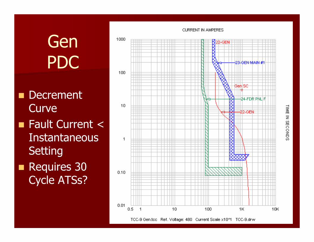
GenPDC
� Decrement Curve
� Fault Current < Instantaneous Setting
� Requires 30 Cycle ATSs?
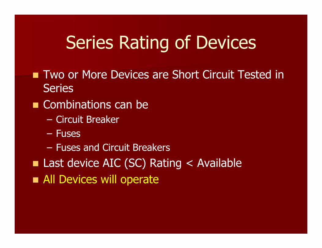
Series Rating of Devices
� Two or More Devices are Short Circuit Tested in Series
� Combinations can be
– Circuit Breaker
– Fuses
– Fuses and Circuit Breakers
� Last device AIC (SC) Rating < Available
� All Devices will operate

SWBD
41638 Amps 3P
PNL-B
36029 Amps 3P
25-Fdr Pnl-B
InterruptingRating 65 kA
26-Lrgst Brnch
InterruptingRating 25 kA
Series Rating of Devices
� UL Listed Combination is Series Rated 65 kA
� No Selective Coordination
� Tip #11 – Do Not Use Series Rated Devices
1
1
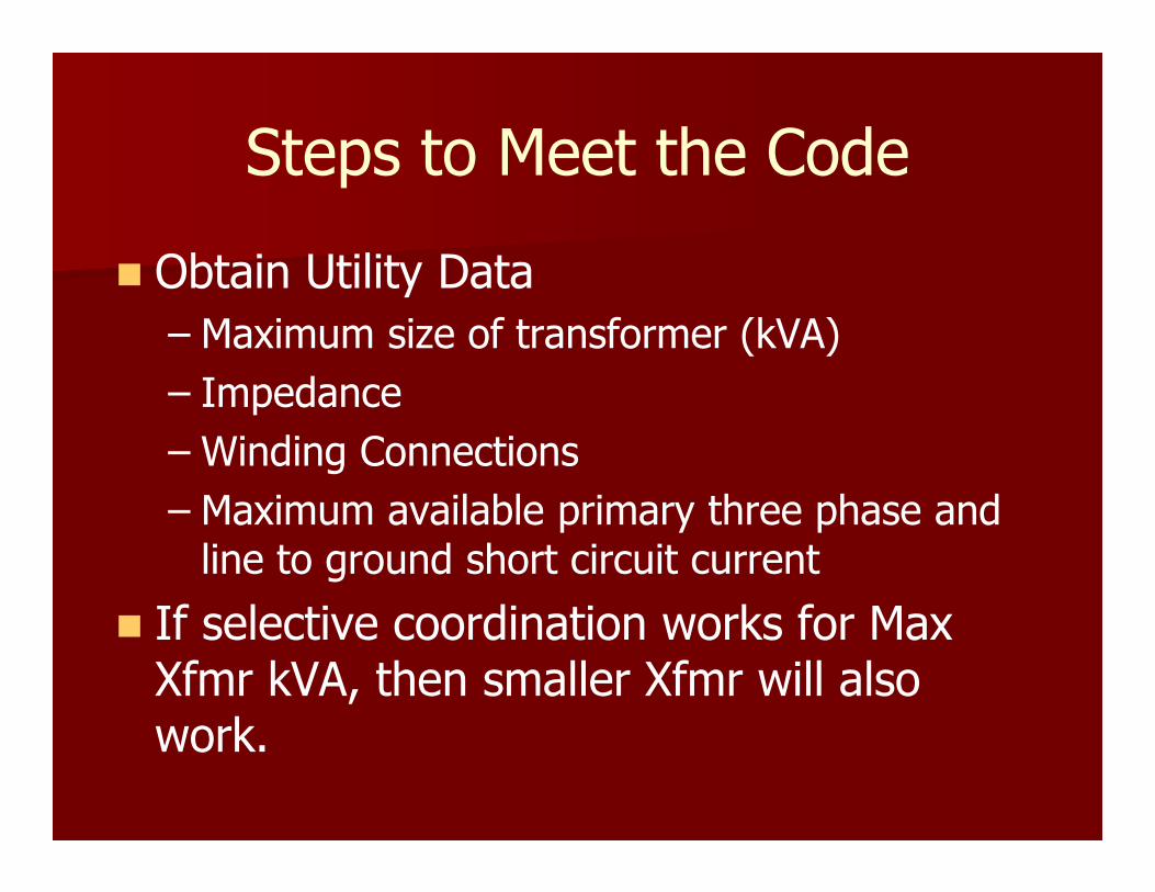
Steps to Meet the Code
� Obtain Utility Data
– Maximum size of transformer (kVA)
– Impedance
– Winding Connections
– Maximum available primary three phase and line to ground short circuit current
� If selective coordination works for Max Xfmr kVA, then smaller Xfmr will also work.
Steps to Meet the Code
� Model the distribution system in computer
� Perform Short Circuit Study to determine 3P and L-G faults.
� Determine Equipment Full Load Ratings (FLA)
Steps to Meet the Code
� Determine protective device
– Standard Ampere Rating (NEC 240.6)
– Short circuit interrupting rating (AIC)
– Downstream coordination current (DCC)
� Tip #12 – Put the SC numbers on the One Line Drawing
Steps to Meet the Code - Circuit Breakers
� Choose a device manufacturer
� Use NEC, DCC and Circuit Breaker Selection Table
� Pick circuit breakers with instantaneous trips above the DCC.
Steps to Meet the Code - Circuit Breakers
� Plot breaker curves to– Verify selective coordination
– Determine device settings
� For new design projects – Repeat above steps for other manufactures
– Create detailed specifications for competitive bidding
– Specify the Breaker Trip Unit Types (T/M or SS) and Instantaneous Override Values.

Steps to Meet the Code - Circuit Breakers
� Tip #13 - Add to Project Specifications:
“Where indicated on one line drawing, breakers must have trip units with Instantaneous setting or override ampere rating 110% above the values shown on one line drawing.”

Steps to Meet the Code - Fuses
� Use Selectivity Ratio Guide to determine fuse sizes.
� Verify Generator Breaker and Downstream Fuses will coordinate.
� Repeat for multiple fuse manufactures for competitive bidding.
517.17 Ground-Fault Protection.
� (C) Selectivity.
– Ground-fault protection for operation of the service and feeder disconnecting means shall be fully selective such that the feeder device, but not the service device, shall open on ground faults on the load side of the feeder device.
Ground-Fault Protection
� Code Requires Ground Fault Selective Coordination for Main and Feeders(medical facilities) only.
� Code does not state that Ground Fault Protection Must Coordinate with the Phase Protection.
� Considered a different protection scheme
� Maximum Pickup setting is 1,200 Amperes
� Maximum Time Delay setting is 0.5 sec.
Ground-Fault Protection
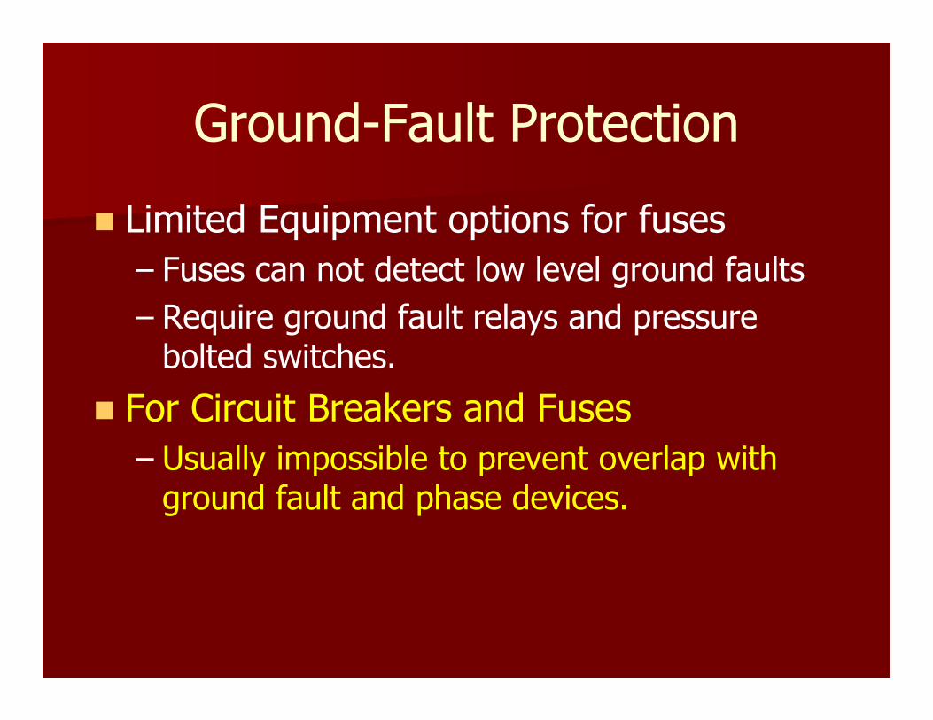
� Limited Equipment options for fuses
– Fuses can not detect low level ground faults
– Require ground fault relays and pressure bolted switches.
� For Circuit Breakers and Fuses
– Usually impossible to prevent overlap with ground fault and phase devices.

More Problems with the Code
� Modifications or additions to a facility.
� How far do you go to implement selective coordination?
� Small Transformers (15-45 kVA) and Panelboards
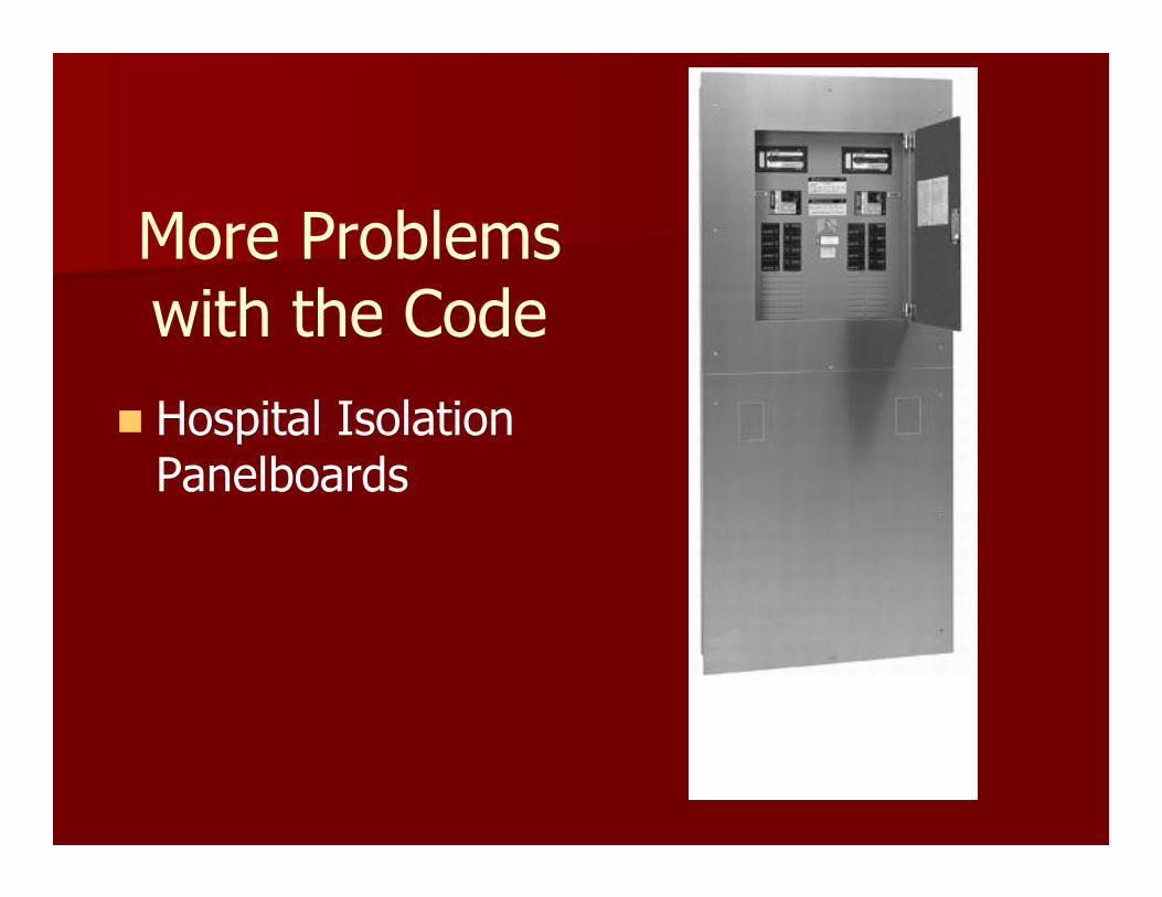
More Problems with the Code
� Hospital Isolation Panelboards

More Problems with the Code
� Utility Transformer Sizing
– NEC forces designers to over design a building.
– Actual load 1st year is less than 50% of the design demand.
– Utilities size transformers 30 – 50% of the designers demand load.
– Utility fuse overlaps with downstream mains and feeder breakers.

Undersized Utility
Transformers
� What the design engineer thinks the size will be. (2000 kVA)
� What the utility installs. (750 kVA)
More Problems with the Code
� Are we sacrificing reliability for safety???
� Decrease in levels of OCPD means...� Elimination of mains in Panelboards
� Feed thru lugs used for riser panelboards
� Longer device delays usually causes higher Arc Flash Energy levels.

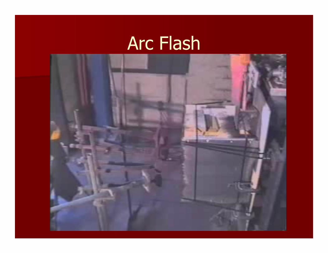
�Arc Flash: Violent eruption of energy from an
electrical source.
� Arc temperature can reach 35,000°F.
� Fatal burns can occur at distances over 10 feet.
� Over half of all arc flashes occur at 277 volts.
Arc Flash
Arc Flash

Arc Flash – Breaker Racking
Arc Flash Energy Calculations
� Incident Energy Levels (HRC) are dependent on: – Level of arcing fault current
– Upstream device clearing time.
� Multiple Sources can change the value of fault current.
� Changes in fault current can change device operating times.
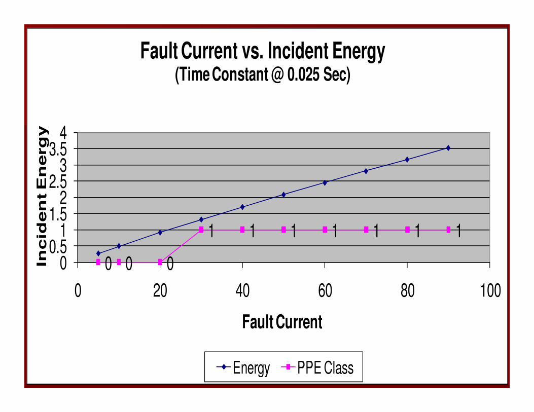
Current Vs Energy Levels
0 0 0
1 1 1 1 1 1 1
00.5
11.5
22.5
33.5
4
0 20 40 60 80 100
Incid
en
t E
nerg
y
Fault Current
Fault Current vs. Incident Energy (Time Constant @ 0.025 Sec)
Energy PPE Class
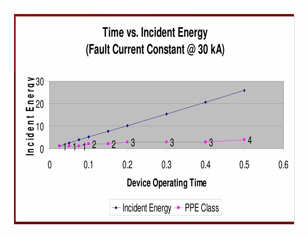
Time Vs Energy LevelsTime vs. Incident Energy
(Fault Current Constant @ 30 kA)
1 1 1 2 2 3 3 3 40
10
20
30
0 0.1 0.2 0.3 0.4 0.5 0.6
Device Operating Time
Inc
ide
nt
En
erg
y
Incident Energy PPE Class

Arc Flash Energy
� Intentionally adding a delay between OCPDs to achieve selective coordination will most likely increase the arc flash energy
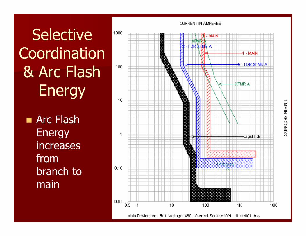
Selective Coordination & Arc Flash Energy
� Arc Flash Energy increases from branch to main
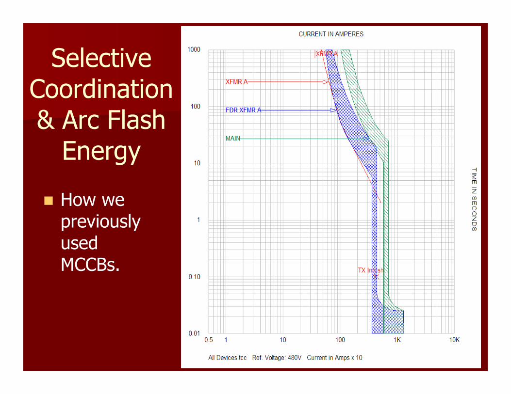
Selective Coordination & Arc Flash Energy
� How we previously used MCCBs.
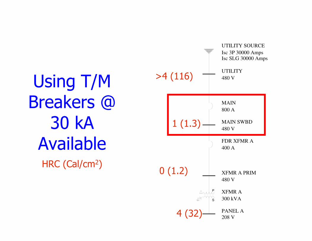
Using T/M Breakers @
30 kA Available
UTILITY
480 V
UTILITY SOURCE
Isc 3P 30000 AmpsIsc SLG 30000 Amps
MAIN SWBD
480 V
XFMR A PRIM
480 V
S
P XFMR A
300 kVA
PANEL A
208 V
MAIN
800 A
FDR XFMR A
400 A
HRC (Cal/cm2)
4 (32)
1 (1.3)
0 (1.2)
>4 (116)
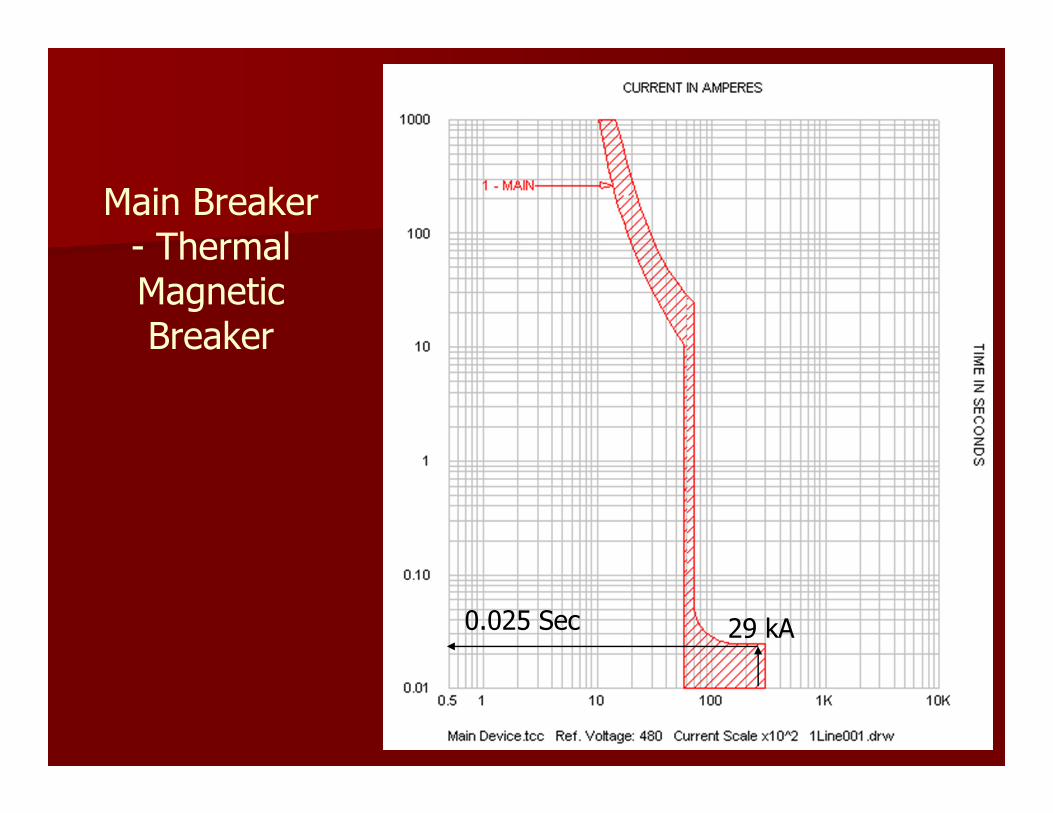
Main Breaker - Thermal Magnetic Breaker
29 kA0.025 Sec

Using T/M Breakers @
30 kA Available
UTILITY
480 V
UTILITY SOURCE
Isc 3P 30000 AmpsIsc SLG 30000 Amps
MAIN SWBD
480 V
XFMR A PRIM
480 V
S
P XFMR A
300 kVA
PANEL A
208 V
MAIN
800 A
FDR XFMR A
400 A
HRC (Cal/cm2)
4 (32)
1 (1.3)
0 (1.2)
>4 (116)
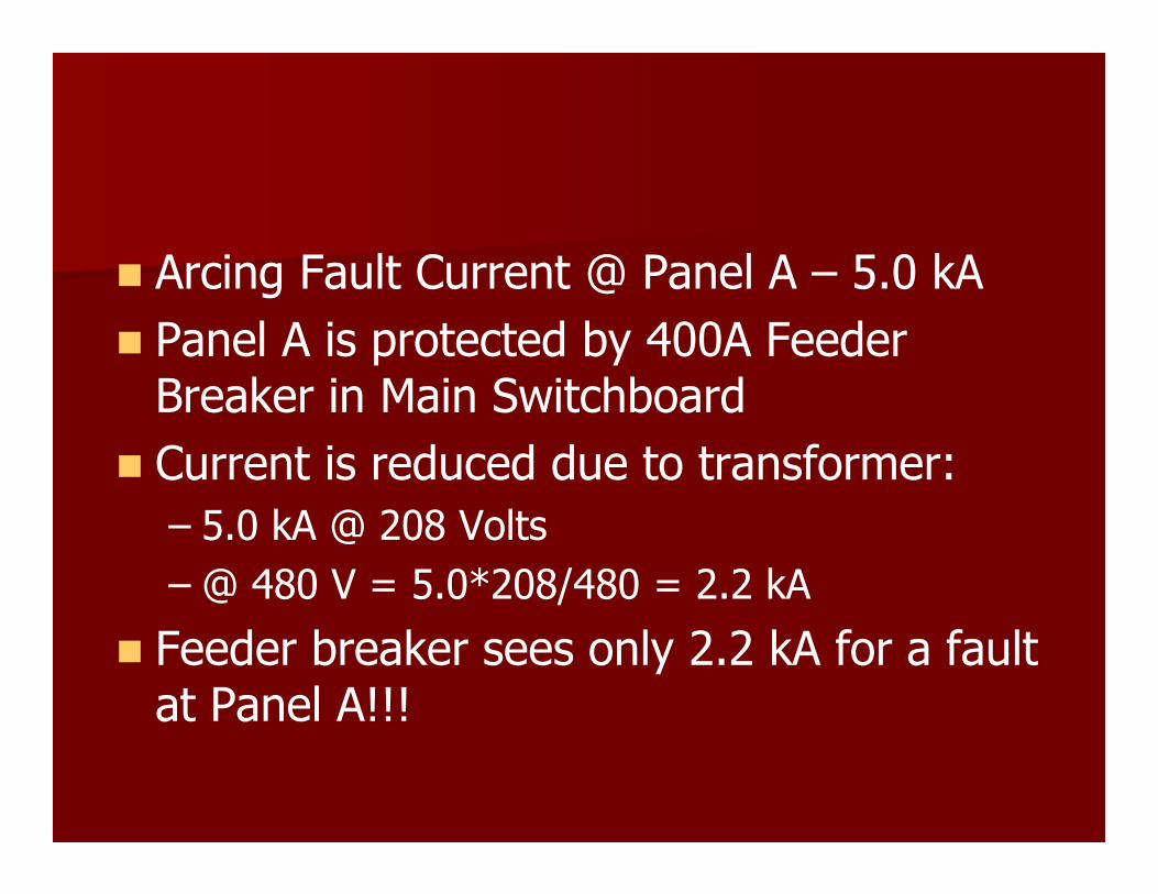
� Arcing Fault Current @ Panel A – 5.0 kA
� Panel A is protected by 400A Feeder Breaker in Main Switchboard
� Current is reduced due to transformer:
– 5.0 kA @ 208 Volts
– @ 480 V = 5.0*208/480 = 2.2 kA
� Feeder breaker sees only 2.2 kA for a fault at Panel A!!!
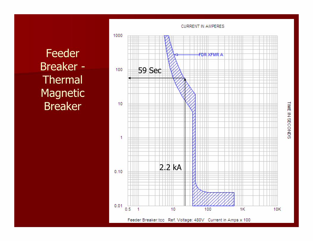
Feeder Breaker -Thermal Magnetic Breaker
2.2 kA
59 Sec

Selective Coordination & Arc Flash Energy
� Main and Feeder Breakers with (LS) Trip Units
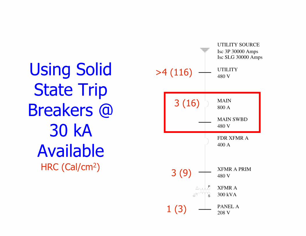
Using Solid State Trip Breakers @
30 kA Available
1 (3)
3 (16)
3 (9)
>4 (116) UTILITY
480 V
UTILITY SOURCE
Isc 3P 30000 AmpsIsc SLG 30000 Amps
MAIN SWBD
480 V
XFMR A PRIM
480 V
S
P XFMR A
300 kVA
PANEL A
208 V
MAIN
800 A
FDR XFMR A
400 A
HRC (Cal/cm2)
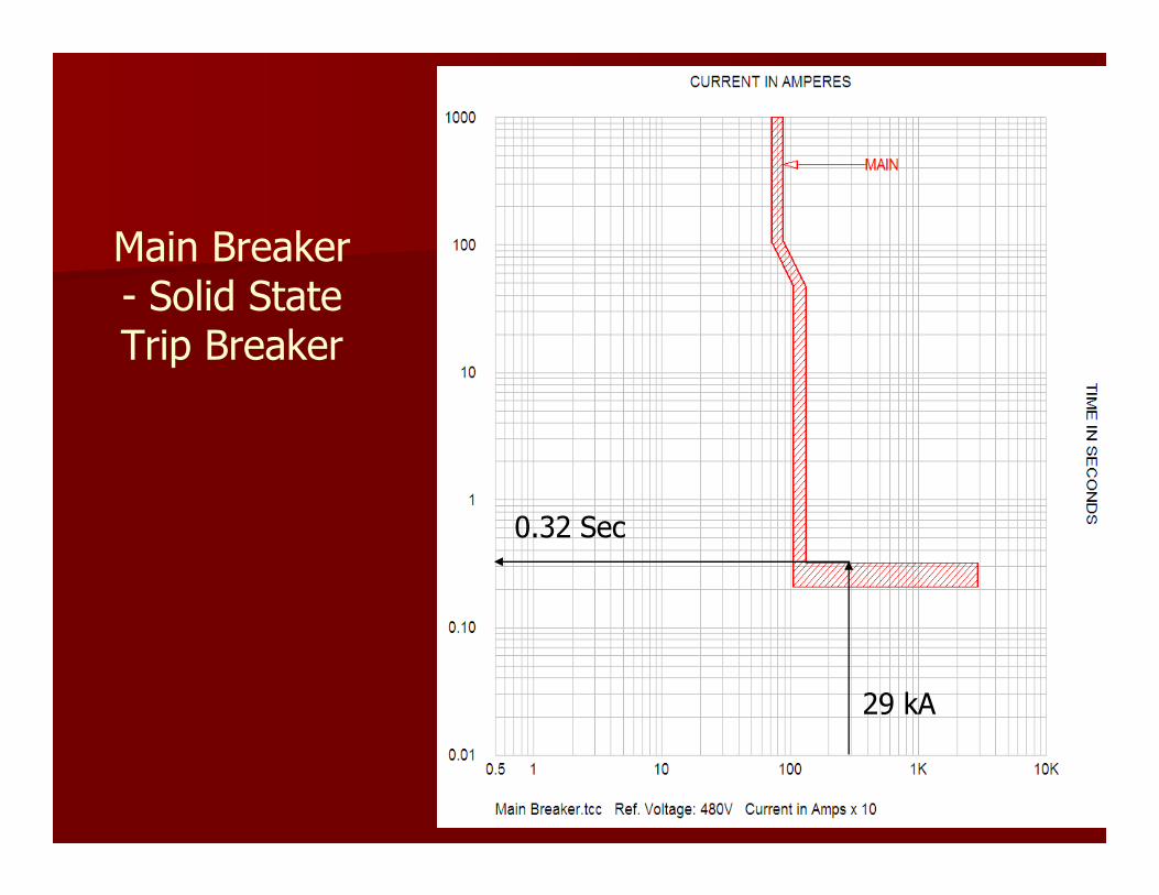
Main Breaker - Solid State Trip Breaker
29 kA
0.32 Sec
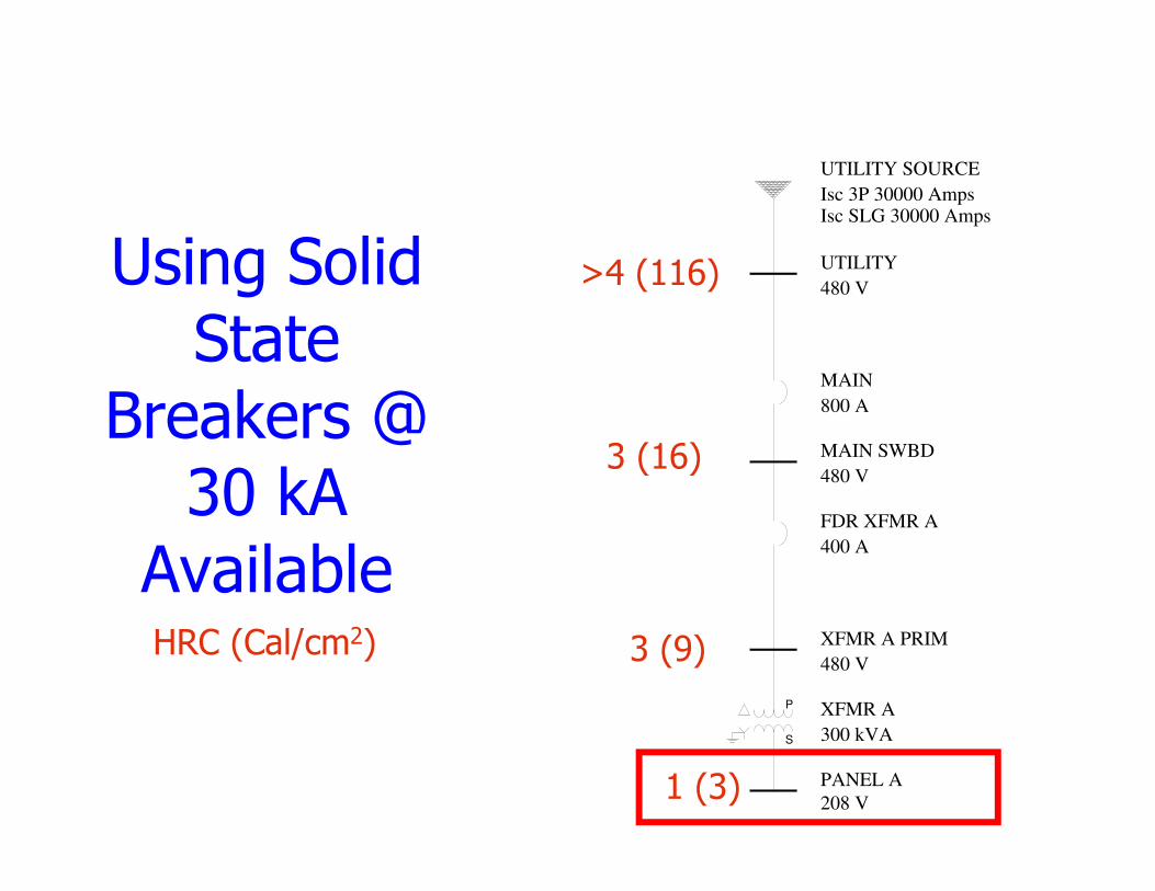
Using Solid State
Breakers @ 30 kA
Available
1 (3)
3 (16)
3 (9)
>4 (116) UTILITY
480 V
UTILITY SOURCE
Isc 3P 30000 AmpsIsc SLG 30000 Amps
MAIN SWBD
480 V
XFMR A PRIM
480 V
S
P XFMR A
300 kVA
PANEL A
208 V
MAIN
800 A
FDR XFMR A
400 A
HRC (Cal/cm2)

� Arcing Fault Current @ Panel A – 5.0 kA
� Panel A is protected by 400A Feeder Breaker in Main Switchboard
� Current is reduced due to transformer:
– 5.0 kA @ 208 Volts
– @ 480 V = 5.0*208/480 = 2.2 kA
� Feeder breaker sees only 2.2 kA for a fault at Panel A!!!

Feeder Breaker -Solid State Trip Breaker
2.2 kA
0.21 Sec
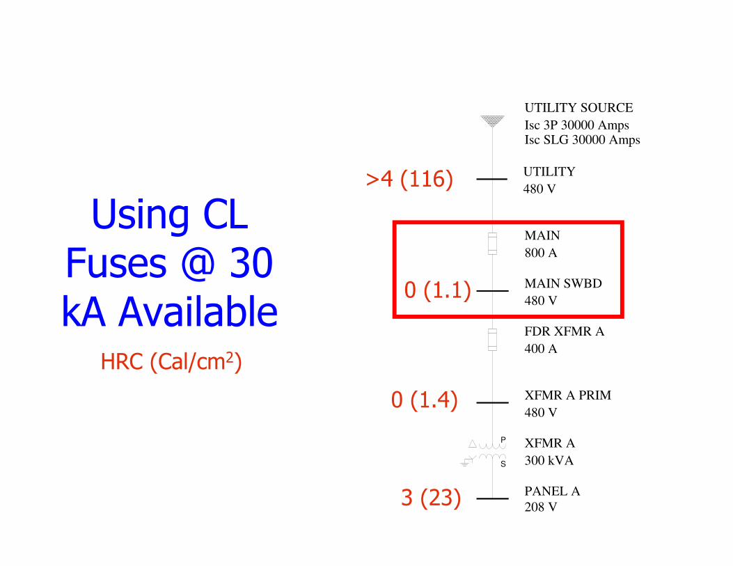
Using CL Fuses @ 30 kA Available
UTILITY
480 V
UTILITY SOURCE
Isc 3P 30000 AmpsIsc SLG 30000 Amps
MAIN SWBD
480 V
XFMR A PRIM
480 V
S
P XFMR A
300 kVA
PANEL A
208 V
MAIN
800 A
FDR XFMR A
400 A
HRC (Cal/cm2)
3 (23)
0 (1.1)
0 (1.4)
>4 (116)

Main- Current Limiting Fuse
15.5kA
0.004 Sec
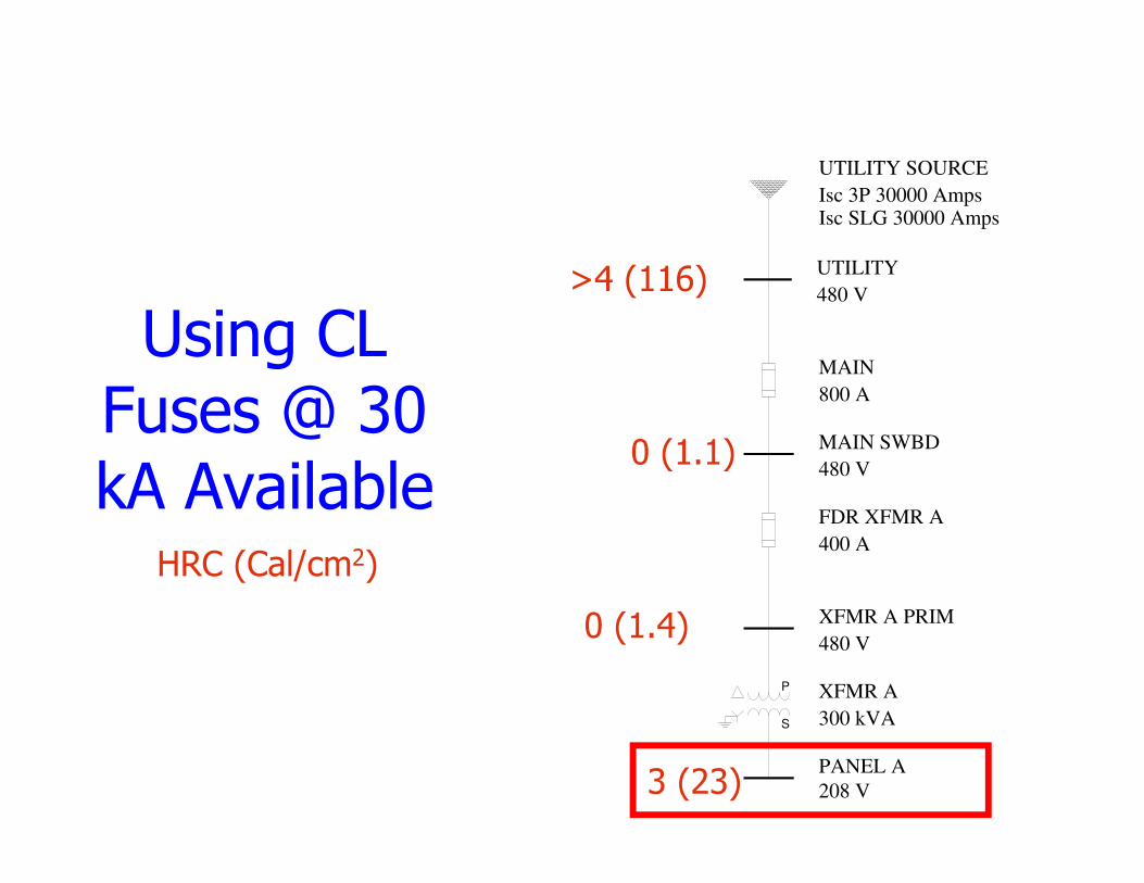
Using CL Fuses @ 30 kA Available
3 (23)
0 (1.1)
0 (1.4)
>4 (116) UTILITY
480 V
UTILITY SOURCE
Isc 3P 30000 AmpsIsc SLG 30000 Amps
MAIN SWBD
480 V
XFMR A PRIM
480 V
S
P XFMR A
300 kVA
PANEL A
208 V
MAIN
800 A
FDR XFMR A
400 A
HRC (Cal/cm2)

� Arcing Fault Current @ Panel A – 5.0 kA
� Panel A is protected by 400A Feeder Fuse in Main Switchboard
� Current is reduced due to transformer:
– 5.0 kA @ 208 Volts
– @ 480 V = 5.0*208/480 = 2.2 kA
� Feeder fuse sees only 2.2 kA for a fault at Panel A!!!
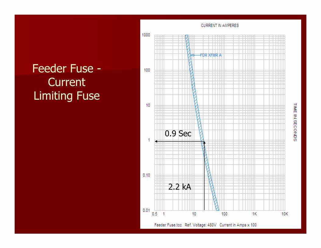
0.9 Sec
Feeder Fuse -Current
Limiting Fuse
2.2 kA
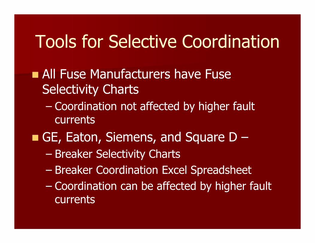
Tools for Selective Coordination
� All Fuse Manufacturers have Fuse Selectivity Charts
– Coordination not affected by higher fault currents
� GE, Eaton, Siemens, and Square D –
– Breaker Selectivity Charts
– Breaker Coordination Excel Spreadsheet
– Coordination can be affected by higher fault currents
Tools for Selective Coordination
� Siemens EasyTCC software program
� SKM PowerTools for windows
– Special Selective Coordination Feature
� Any others I have not mentioned??
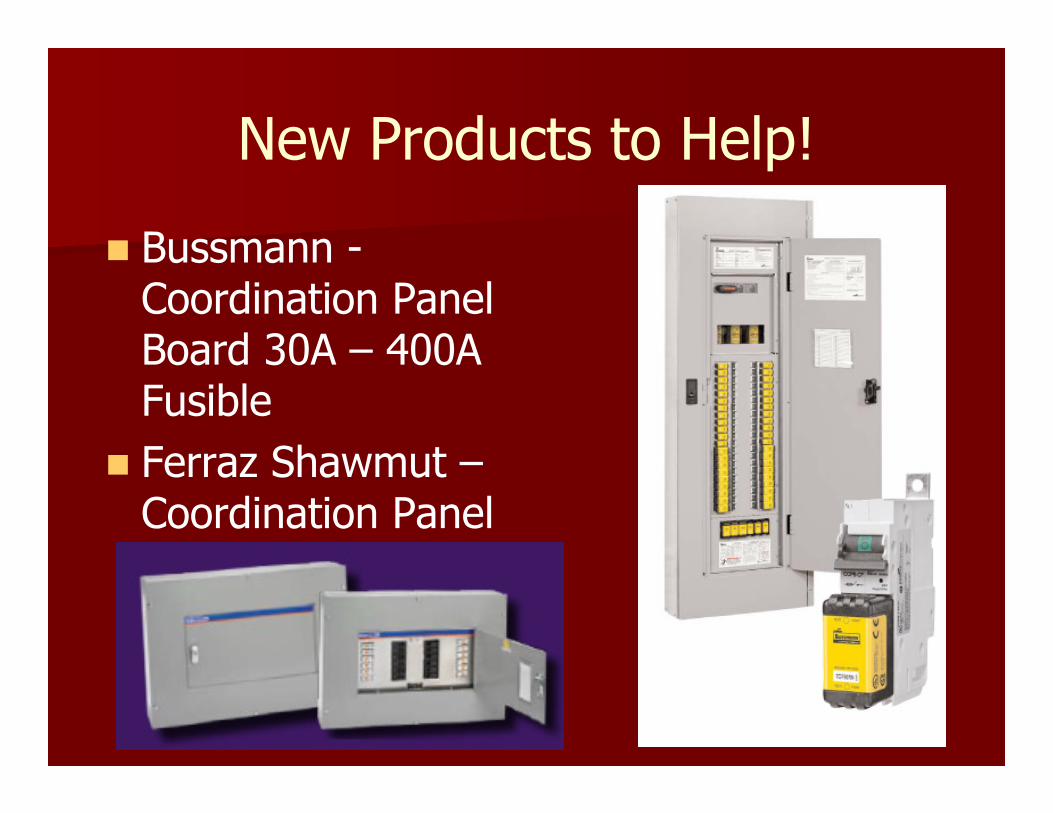
New Products to Help!
� Bussmann -Coordination Panel Board 30A – 400A Fusible
� Ferraz Shawmut –Coordination Panel
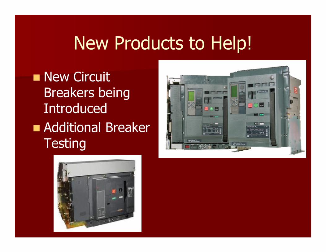
New Products to Help!
� New Circuit Breakers being Introduced
� Additional Breaker Testing

Resources and Additional Info
� http://www.geindustrial.com/solutions/engineers/selective_coordination.html
� http://www.eaton.com/Electrical/Consultants/SelectiveCoordination/index.htm
� http://www.schneider-electric.us/sites/us/en/customers/consulting-engineer/selective-coordination.page
Resources and Additional Info� http://www.sea.siemens.com/us/Support/Consulting-Engineers/Pages/SelectiveCoordination.aspx
� http://www1.cooperbussmann.com/2/SelectiveCoordination.html
� http://us.ferrazshawmut.com/resources/articles-white-papers.cfm
� http://us.ferrazshawmut.com/resources/online-training.cfm
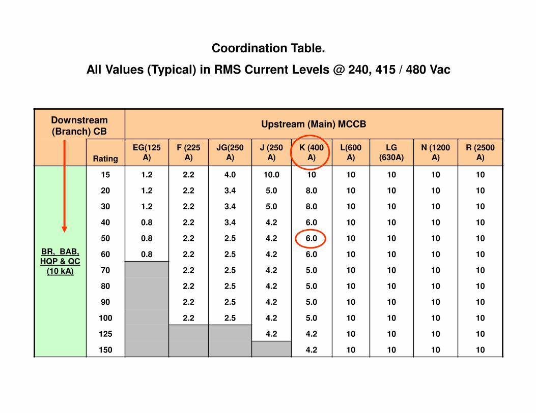
Coordination Table.
All Values (Typical) in RMS Current Levels @ 240, 415 / 480 Vac
Downstream (Branch) CB
Upstream (Main) MCCB
Rating
EG(125 A)
F (225 A)
JG(250 A)
J (250 A)
K (400 A)
L(600 A)
LG (630A)
N (1200 A)
R (2500 A)
BR, BAB, HQP & QC
(10 kA)
15 1.2 2.2 4.0 10.0 10 10 10 10 10
20 1.2 2.2 3.4 5.0 8.0 10 10 10 10
30 1.2 2.2 3.4 5.0 8.0 10 10 10 10
40 0.8 2.2 3.4 4.2 6.0 10 10 10 10
50 0.8 2.2 2.5 4.2 6.0 10 10 10 10
60 0.8 2.2 2.5 4.2 6.0 10 10 10 10
70 2.2 2.5 4.2 5.0 10 10 10 10
80 2.2 2.5 4.2 5.0 10 10 10 10
90 2.2 2.5 4.2 5.0 10 10 10 10
100 2.2 2.5 4.2 5.0 10 10 10 10
125 4.2 4.2 10 10 10 10
150 4.2 10 10 10 10
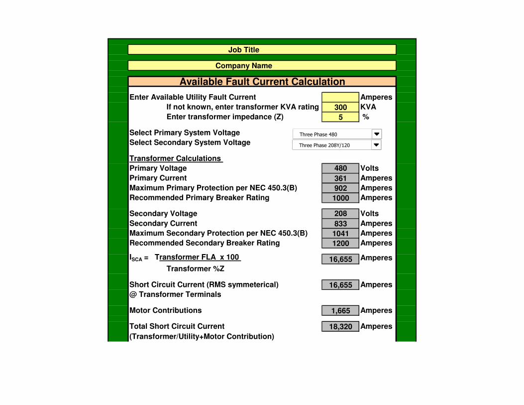
Job Title
Company Name
Available Fault Current Calculation
Enter Available Utility Fault Current Amperes
If not known, enter transformer KVA rating 300 KVA
Enter transformer impedance (Z) 5 %
Select Primary System Voltage
Select Secondary System Voltage
Transformer Calculations
Primary Voltage 480 Volts
Primary Current 361 Amperes
Maximum Primary Protection per NEC 450.3(B) 902 Amperes
Recommended Primary Breaker Rating 1000 Amperes
Secondary Voltage 208 Volts
Secondary Current 833 Amperes
Maximum Secondary Protection per NEC 450.3(B) 1041 Amperes
Recommended Secondary Breaker Rating 1200 Amperes
ISCA = Transformer FLA x 100 16,655 Amperes
Transformer %Z
Short Circuit Current (RMS symmeterical) 16,655 Amperes
@ Transformer Terminals
Motor Contributions 1,665 Amperes
Total Short Circuit Current 18,320 Amperes
(Transformer/Utility+Motor Contribution)
Three Phase 208Y/120
Three Phase 480

Select Conductor Data Between Main MCCB and Branch MCCB
Select Conductor Type & Raceway
Charisteristics
Select Conductor Size
Enter Conductor Length 100 Feet
Enter Number of Conductors / Phase 1
Fault Current @ Load Terminals of Branch MCCB 7,815 Amperes
Select Transformer Secondary MCCB
Select Downstream Branch MCCB
Coordination Level 2,300 Amperes
Results Select Larger Frame Size
Copper in Metalic Raceway
250 kcmil
JG(250 A)
F 100A

Circuit Breaker Selection Table
� Table Used to Quickly Select Breakers that maycoordinate.
� Easily Sorted in Excel.

Circuit Breaker Selection Table

Example 1
� Determine the Short Circuit Currents
� Determine the breaker type
– SWBD Main (4000 Amp)
– Feeder to ATS (200 Amp)
– Panelboard Main (200 Amp)
– Largest Feeder is 70A KH AMP
32-MSWBD MAIN
SWBD
41638 Amps 3P41081 Amps SLG
12-Fdr ATS-E
12-PNL-A MAIN
PNL-A - 250 A
30933 Amps 3P27901 Amps SLG
E N
ATS 260 Amp
76-Lrgst Brnch

32-MSWBD MAIN
SQUARE D NW40H Sensor/Trip 4000 ASettings Phase LTPU/LTD (A 0.4-1.0 x S) 1 (4000A); 0.5 STPU (1.5-10 x LTPU) 5 (20000A) STD (INST-0.4) 0.3(I^2 T Out) INST (2-15 x S) 15 (60000A)
12-Fdr ATS-E
SQUARE D NT08H Sensor/Trip 400 ASettings Phase LTPU/LTD (A 0.4-1.0 x S) 0.5 (200A); 24 STPU (1.5-10 x LTPU) 6 (1200A) STD (INST-0.4) 0.2(I^2 T Out) INST Override Fixed (40000A)
Example 1

12-PNL-A MAIN
SQUARE D NT08H Sensor/Trip 400 ASettings Phase LTPU/LTD (A 0.4-1.0 x S) 0.5 (200A); 16 STPU (1.5-10 x LTPU) 5 (1000A) STD (INST-0.4) 0.1(I^2 T Out) INST Override Fixed (40000A)
76-Lrgst Brnch
SQUARE D KH Sensor/Trip 70 ASettings Phase Thermal Curve (Fixed) INST (5-10 x Trip) 10.0 (700A)
Example 1

Example 1
� Determine the
– SWBD Main -
– Feeder to ATS
– PNLBD Main
– Largest Feeder is 70A KH AMP
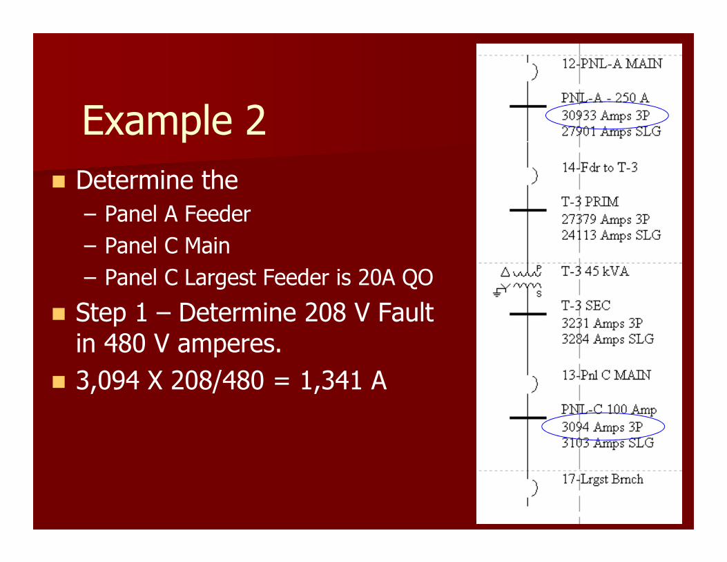
Example 2
� Determine the
– Panel A Feeder
– Panel C Main
– Panel C Largest Feeder is 20A QO
� Step 1 – Determine 208 V Fault in 480 V amperes.
� 3,094 X 208/480 = 1,341 A

Example 2
� Pick 125 Amp Feeder Breaker T-3
– Instantaneous OR > 1,341
– 1,341 / 125 = 10.7 (Can not use T/M)
– Must Use SS Trip
� Pick Panel C 100 Ampere Main
– Must Coordinate with Largest Branch Breaker

Example 2
13-Pnl C MAIN
SQUARE D PG Sensor/Trip 250 ASettings Phase LTPU/LTD (A 0.4-1.0 x S) 0.4 (100A); 4 STPU (1.5-10 x LTPU) 10 (1000A) STD (0-0.4) 0.1(I^2 T In) INST Override Fixed (24000A)
17-Lrgst BrnchSQUARE D QO3 Sensor/Trip 20 ASettings Phase Fixed

12-PNL-A MAIN
SQUARE D NT08H Sensor/Trip 400 ASettings Phase LTPU/LTD (A 0.4-1.0 x S) 0.5 (200A); 16 STPU (1.5-10 x LTPU) 5 (1000A) STD (INST-0.4) 0.2(I^2 T Out) INST Override Fixed (40000A)
14-Fdr to T-3
SQUARE D LE Sensor/Trip 250 APlug 250 ASettings Phase LTPU (0.5-1.0 x P) 0.5 (125A) LTD (2-14 Sec.) 2 STPU (2-8 x P) 2.5 (625A) STD (0.1-0.5 Sec.) 0.1(I^2 T Out) INST (2.5-8 x P) 8.0 (2000A)
Example 2

Example 2

205
Requires
proper engineering,
Specification,
Installation, and Testing
Selective Coordination -Ensuring Compliance

Selective Coordination –Ensuring Compliance
� Engineer
– Designs must allow selective coordination –Use less levels of OCPDs.
– For competitive bidding, design should be generic and simple.
– Require that PDC study be done after manufacture has provided submittals for proposed equipment.

Selective Coordination –Ensuring Compliance
� Contractors
– Purchase and install OCPDs as specified.
– Substitutions must be approved by the designer and verified that is can be selectively coordinated.
– Make sure devices are set per the PDC study.
– Test the devices to verify proper operation.
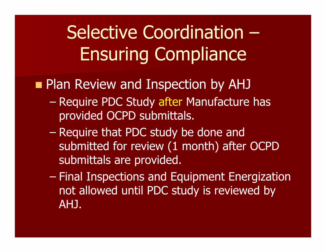
Selective Coordination –Ensuring Compliance
� Plan Review and Inspection by AHJ
– Require PDC Study after Manufacture has provided OCPD submittals.
– Require that PDC study be done and submitted for review (1 month) after OCPD submittals are provided.
– Final Inspections and Equipment Energization not allowed until PDC study is reviewed by AHJ.

209
Selective Coordination Check Listhttp://www.cooperindustries.com/content/dam/public/bussmann/Electrical/Resources/Solution%20Center/electrical_inspector_tools/BUS_Ele_Selective_Coord_Req_ChkList.pdf

Summary
� You must change the way you design circuits for:– Emergency
– Standby
– Elevators
– Fire Pumps
� Manufacturers must provide:– New Equipment to meet the code
– Tools (tables, spreadsheets, charts)
– I2T Withstand curves for Equipment

Need more Information
� www.powerstudies.com
– Articles
– Links
– Specifications for Power System Studies
� Short Circuit
� Protective Device Coordination
� Arc Flash Hazard

Questions??
Thank you for your time!

Who are we?
� Electrical Engineering Consulting Firm
� We Specialize in performing Power System Studies
� We teach Electrical Safety Training Seminars (LV & HV)
� 90% of our business is in performing Power System Studies

Where are we located?
� Our main office is located in Covington (Seattle), WA.
� Branch Office located in San Francisco
� Our territory is Western third and Northeast of US
� We have also done studies for clients in Russia, Central, and South America