Meeting the design concept: The integration … the design concept: The integration challenges of...
12
Author’s Biography Oliver Simmonds works as a Lead Engineer in the Naval Systems and Projects division of GE’s Power Conversion business. He initially completed a Masters degree in Mechanical Engineering at the University of Bath in the UK, and then did a Distance Learning MSc in Electrical Power Systems. A Chartered Engineer, he has lead several major projects ranging from future power distribution systems to extensive studies into the Arc Flash Hazard. Most recently he has been leading a team to design and supply the power and propulsion system for the Norwegian Logistics & Support Vessel. Chris Hodge is the Chief Electrical Engineer of BMT Defence Services having served in the Royal Navy in conventional and nuclear submarines. He was the Chairman of the Board of Trustees of the IMarEST from 2009 to 2015 and is now serving as its 115 th President. Thomas Couch is a Principal Naval Engineer within BMT Defence Services. After graduating in Marine Systems Technology from the University of Plymouth in 1997 he joined BMT Defence Services in 1998. A Chartered Engineer, he has been engaged on various engineering roles within the Aircraft Carrier Alliance notably in the role of Diesel Generator Integration Engineer and Technical Lead for Power Generation. He led teams involved in the delivery of the Power and Propulsion system designs for the UK MoD MARS Fleet Tanker and the Norwegian Logistics and Support Vessel. Jeremy Fisher is a Principal Naval Engineer and the Deputy Head of Naval Engineering within BMT Defence Services. He graduated in Mechanical Engineering from the University of the West England in Bristol in 2003 and completed a Distance Learning MSc in Engineering and Management. A Chartered Engineer, he has been engaged on various engineering roles within Aircraft Carrier Alliance notably in the roles of Lead Engineer for Steering and Stabiliser Systems and Propulsion & Manoeuvring Technical Lead. He led the Norwegian Logistics and Support Vessel bid design team and subsequently led the delivery of the Electrical system design. Meeting the design concept: The integration challenges of advanced hybrid systems O J Simmonds * MEng MSc CMarEng CEng MIMarEST Professor C G Hodge # OBE MSc CMarEng CEng FIMarEST FREng T Couch # BEng (Hons) CMarEng CEng MIMarEST J Fisher # BEng (Hons) MSc CMarEng CEng MIMarEST * GE Power Conversion, Rugby, UK # BMT Defence Services Ltd, Bath, UK * Corresponding Author. Email: [email protected] Synopsis In recent years there has been a marked shift towards hybrid (electrical & mechanical) power and propulsion systems. Whilst the main reasons for adopting hybrids have been for efficiency and through-life fuel savings, they also offer increased flexibility for varying operating profiles. New advanced hybrids combine a large main diesel engine with an active-front-end variable speed electric drive in combination with an induction motor, that can operate as both a motor (Power Take In – PTI) and a generator (Power Take Off – PTO), to drive a controllable pitch propeller through a gearbox. This paper, based on recent joint experience, will explore how a hybrid concept is developed for a typical Naval Auxiliary Vessel, addressing how the design evolves to meet the concept of operations for the platform to deliver the operational need. The various aspects of propulsion and electrical system integration processes and capabilities are addressed including examples of where innovation has been used in machinery and systems to meet variations in operating profile and usage demands for vessels that provide worldwide logistical support. Whilst a hybrid power and propulsion system offers many benefits, it does pose some significant challenges over a conventional mechanical propulsion system with standalone generation, and even some challenges not seen on a full electric power and propulsion system. The paper will address these challenges and demonstrate how they can be mitigated focussing on a whole systems approach and the use of novel techniques. The paper concludes that hybrid propulsion must be designed as a complete system combining the needs of propulsion, ship’s service power supply and equipment type. Integration of the hybrid system as a whole is essential, and the experience, skill and knowledge required to do this should not be underestimated. Keywords: Hybrid; PTI; PTO; Propulsion; Integration; Marine systems 1. Introduction: Moving away from mechanical propulsion Since the mid-20 th century the trend for Naval ship propulsion has moved away from a purely mechanical system towards an electric one. Historically, both hybrid-electric and full-electric propulsion systems have been utilised, with some of the early hybrid systems acting as a ‘first-step’ away from mechanical propulsion. For example, the Type 23 ‘Duke’ Class Frigates, designed back during the 1980s, adopted a hybrid propulsion system, using electric drive for quiet anti-submarine operations, and gas-turbines for higher speeds (Simmonds, 2013). The hybrid designs presented in this paper are an advancement on this concept.
Transcript of Meeting the design concept: The integration … the design concept: The integration challenges of...

Author’s Biography
Oliver Simmonds works as a Lead Engineer in the Naval Systems and Projects division of GE’s Power Conversion business.
He initially completed a Masters degree in Mechanical Engineering at the University of Bath in the UK, and then did a
Distance Learning MSc in Electrical Power Systems. A Chartered Engineer, he has lead several major projects ranging from
future power distribution systems to extensive studies into the Arc Flash Hazard. Most recently he has been leading a team to
design and supply the power and propulsion system for the Norwegian Logistics & Support Vessel.
Chris Hodge is the Chief Electrical Engineer of BMT Defence Services having served in the Royal Navy in conventional and
nuclear submarines. He was the Chairman of the Board of Trustees of the IMarEST from 2009 to 2015 and is now serving as
its 115th President.
Thomas Couch is a Principal Naval Engineer within BMT Defence Services. After graduating in Marine Systems
Technology from the University of Plymouth in 1997 he joined BMT Defence Services in 1998. A Chartered Engineer, he
has been engaged on various engineering roles within the Aircraft Carrier Alliance notably in the role of Diesel Generator
Integration Engineer and Technical Lead for Power Generation. He led teams involved in the delivery of the Power and
Propulsion system designs for the UK MoD MARS Fleet Tanker and the Norwegian Logistics and Support Vessel.
Jeremy Fisher is a Principal Naval Engineer and the Deputy Head of Naval Engineering within BMT Defence Services. He
graduated in Mechanical Engineering from the University of the West England in Bristol in 2003 and completed a Distance
Learning MSc in Engineering and Management. A Chartered Engineer, he has been engaged on various engineering roles
within Aircraft Carrier Alliance notably in the roles of Lead Engineer for Steering and Stabiliser Systems and Propulsion &
Manoeuvring Technical Lead. He led the Norwegian Logistics and Support Vessel bid design team and subsequently led the
delivery of the Electrical system design.
Meeting the design concept: The integration challenges of advanced hybrid systems
O J Simmonds* MEng MSc CMarEng CEng MIMarEST
Professor C G Hodge# OBE MSc CMarEng CEng FIMarEST FREng
T Couch# BEng (Hons) CMarEng CEng MIMarEST
J Fisher# BEng (Hons) MSc CMarEng CEng MIMarEST
* GE Power Conversion, Rugby, UK
# BMT Defence Services Ltd, Bath, UK
* Corresponding Author. Email: [email protected]
Synopsis
In recent years there has been a marked shift towards hybrid (electrical & mechanical) power and propulsion
systems. Whilst the main reasons for adopting hybrids have been for efficiency and through-life fuel savings,
they also offer increased flexibility for varying operating profiles. New advanced hybrids combine a large
main diesel engine with an active-front-end variable speed electric drive in combination with an induction
motor, that can operate as both a motor (Power Take In – PTI) and a generator (Power Take Off – PTO), to
drive a controllable pitch propeller through a gearbox.
This paper, based on recent joint experience, will explore how a hybrid concept is developed for a typical
Naval Auxiliary Vessel, addressing how the design evolves to meet the concept of operations for the platform
to deliver the operational need. The various aspects of propulsion and electrical system integration processes
and capabilities are addressed including examples of where innovation has been used in machinery and
systems to meet variations in operating profile and usage demands for vessels that provide worldwide
logistical support.
Whilst a hybrid power and propulsion system offers many benefits, it does pose some significant challenges
over a conventional mechanical propulsion system with standalone generation, and even some challenges not
seen on a full electric power and propulsion system. The paper will address these challenges and demonstrate
how they can be mitigated focussing on a whole systems approach and the use of novel techniques.
The paper concludes that hybrid propulsion must be designed as a complete system combining the needs of
propulsion, ship’s service power supply and equipment type. Integration of the hybrid system as a whole is
essential, and the experience, skill and knowledge required to do this should not be underestimated.
Keywords: Hybrid; PTI; PTO; Propulsion; Integration; Marine systems
1. Introduction: Moving away from mechanical propulsion
Since the mid-20th
century the trend for Naval ship propulsion has moved away from a purely mechanical system
towards an electric one. Historically, both hybrid-electric and full-electric propulsion systems have been utilised,
with some of the early hybrid systems acting as a ‘first-step’ away from mechanical propulsion. For example, the
Type 23 ‘Duke’ Class Frigates, designed back during the 1980s, adopted a hybrid propulsion system, using
electric drive for quiet anti-submarine operations, and gas-turbines for higher speeds (Simmonds, 2013). The
hybrid designs presented in this paper are an advancement on this concept.

Despite the many well published benefits of IFEP (Hodge & Mattick, 1996-2000), it does come at the cost of
greater volume and weight compared to other types of more mechanical based propulsion, and it is often more
expensive to purchase. For an auxiliary support ship there is currently little need for high power levels for next-
generation weapons and sensors, instead low whole life cost and efficiency tend to be the main drivers. A hybrid
mechanical and electric propulsion system is an excellent alternative choice to IFEP for such vessels (Dalton &
McCoy, 2012).
In the context of the vessels considered in this paper, namely Naval Auxiliary Vessels, a hybrid power and
propulsion system offers the greatest flexibility between power generation sources and propulsion prime movers,
low annual fuel consumption and also avoids the running of the prime movers at continuous low loads. This has
been found to be the most suitable arrangement to meet the requirements where low whole life costs are as
important as the maximum sustained speed (Buckingham, 2013 & 2014).
The focus of this paper is on a COmbined Diesel eLectric Or Diesel (CODLOD) arrangement with the added
flexibility that the electrical induction machine can operate as both a motor (Power Take In – PTI) and a
generator (Power Take Off – PTO). A representative layout of this arrangement can be seen in Figure 1. At a
simplistic level, this hybrid system is shared by both the MARS Fleet Tankers (Tide Class) and the Norwegian
Logistics & Support Vessel (LSV), and is the basis of the BMT Aegir design of auxiliary vessels.
Figure 1: CODLOD Hybrid Propulsion with PTI/PTO
2. Power and Propulsion System Design Development
The Preliminary Design stage is critical for the Power and Propulsion design area to validate and mature the
Power and Propulsion system arrangement, key components, and associated operating philosophy (normal and
alternative line-ups) against the specific customer requirements and standards. It also allows for the de-risking
of key areas and for further maturity of the cost estimates to be undertaken. At this stage, it is important to get
the design right by avoiding changes resulting from misinterpretation of customer requirements. Like most key
aspects of a ship design, if a change is required to resolve problems in later design stages this can
disproportionally impact programme, cost and presents ship integration challenges. Therefore relevant
uncertainty allowances and margins should be applied and the maturity of the design should be assessed and
recorded. Generally, this phase is undertaken in support of the bidding process (Couch & Fisher, 2016).
The Basic Design phase takes place following project award. The overall aim of the Basic Design phase is to
provide an increased level of definition of the propulsion system and identified associated systems to
DIESEL
DIESELGEA
RB
OX
DIESEL
GEA
RB
OX
G
DIESELG
HM
HM
Ship’s Service Loads
Ship’s Service Loads
Key:
HM Hybrid Machine
G Generator
demonstrate compliance against contracted customer requirements, to meet class requirements and to further de-
risk key areas.
There is intensive interaction with equipment suppliers and the shipyard in order to de-risk the integration and
operation of the power and propulsion arrangement. This should also include detailed interaction with the
customers and their ship operators in order to make sure that their operating principals are considered within the
design process and to ease their acceptance of the design solution.
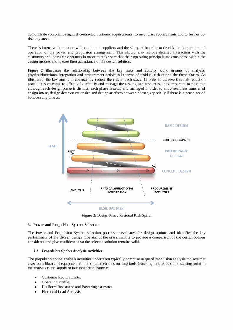
Figure 2 illustrates the relationship between the key tasks and activity work streams of analysis,
physical/functional integration and procurement activities in terms of residual risk during the three phases. As
illustrated, the key aim is to consistently reduce the risk at each stage. In order to achieve this risk reduction
profile it is essential to effectively identify and manage the tasking and resources. It is important to note that
although each design phase is distinct, each phase is setup and managed in order to allow seamless transfer of
design intent, design decision rationales and design artefacts between phases, especially if there is a pause period
between any phases.
Figure 2: Design Phase Residual Risk Spiral
3. Power and Propulsion System Selection
The Power and Propulsion System selection process re-evaluates the design options and identifies the key
performance of the chosen design. The aim of the assessment is to provide a comparison of the design options
considered and give confidence that the selected solution remains valid.
3.1 Propulsion Option Analysis Activities
The propulsion option analysis activities undertaken typically comprise usage of propulsion analysis toolsets that
draw on a library of equipment data and parametric estimating tools (Buckingham, 2000). The starting point to
the analysis is the supply of key input data, namely:
Customer Requirements;
Operating Profile;
Hullform Resistance and Powering estimates;
Electrical Load Analysis.

The key outputs of the propulsion option analysis are generally a series of outputs which allow easy comparison
of options, for example graphs similar to those shown in Figure 3 and Figure 4. Figure 3 illustrates for a given
operating profile the corresponding cumulative fuel consumption costs for 3 propulsion design cases showing
whole life cost is lowest for the Hybrid design. Figure 4 illustrates the hourly fuel consumption rate for three
propulsion design cases at different vessel speeds.
Figure 3: Whole Life Cost Comparison
Figure 4: Hourly Fuel Consumption Rate

3.2 Sensitivity Analysis
Variation in customer defined operating profiles for auxiliary vessels can reduce the margin by which the Hybrid
solution provides the lowest whole life cost solution; noting that operating for long durations at high transit
speeds lends itself to a more simplistic diesel mechanical solution. This further supports the need to develop a
common understanding and interpretation of the wider requirements; for example replenishment at sea (RAS)
and its associated electrical power consumption, and propulsion engine loading (Couch & Fisher, 2016).
3.3 Physical and Functional Integration
The Physical/Functional activities provide the required level of definition to de-risk the integration of the Power
and Propulsion scope into the vessel, and the following key documents are created:
Interface Scope Diagrams – For further details please see below;
Power and Propulsion Operating Philosophy – Gives the operator, the client, the shipbuilder and
suppliers an understanding of the Design Intent of both normal and key reversionary operation at the
whole system level covering the main components of the propulsion system as well as electrical
generation and distribution down to main distributed equipment power level (e.g. 440V), as well as
considering key operational safety aspects. This document is only intended to provide an overview of
the Operating Philosophy in order to maintain the Design Intent;
System schematic and Arrangement Drawings - The incremental maturing of the definition of these
system drawings is essential in de-risking the vessel design.
Interface Scope diagrams comprise high level block diagrams which are essential in the definition, review and
agreement of the interfaces between components of the relevant equipment and systems, as well as defining and
agreeing the scope of supply for the components with suppliers. They highlight how some of the hybrid systems
discussed can have more complicated commercial interfaces.
Figure 5: Example Hybrid Propulsion System Interface Scope Diagram
Figure 5 shows an example split of the commercial responsibilities on a typical hybrid system, with each
organisation’s scope of supply shaded differently and the communication paths shown as arrows. As depicted, no
single organisation has control of or responsibility for the end-to-end system (whether in PTI or PTO), and some
of the control and monitoring signals for key components, such as the hybrid converter, are from two different
sources. In practice this can result in significant integration challenges during the detailed design phase. In the
case of Norwegian LSV it has been ultimately up to the shipyard to both lead the integration of an unfamiliar
new hybrid power and propulsion system, and enforce the correct commercial behaviour to successfully integrate
the project. For future projects, a dedicated (and ideally independent) system integrator with complete system
oversight may offer some benefit.
DIESEL GEA
RB
OXHM
Propulsion Control System (PCS)Power
Management System (PMS)
Integrated Platform Management System

4. The Hybrid Option
Figure 6 shows a simplified single-line-diagram view of the CODLOD hybrid system. On each of the two shafts,
a main diesel engine (MDE) and a hybrid machine (HM) drive a controllable pitch propeller (CPP) via a
reduction gearbox. As previously mentioned, the HM can be run as either a motor (driving the shaft) or a
generator (providing electric power for the ship), and it is connected to the main distribution network via a bi-
directional power electronic converter. In addition, two diesel generators (DGs) can supply power for either
electric propulsion or the ship’s service loads.
Figure 6: CODLOD Hybrid Propulsion with PTI/PTO
The efficient running of any vessel is vital when considering its operating philosophy however, the operation of
the hybrid system for the vessel type identified provides some additional challenges in order to define the most
appropriate operating arrangement for each mode of operation. The most appropriate arrangement may range
from being the most efficient arrangement (for example for long distance transit) to the most robust operating
arrangement (for example when operating in restricted waters, or in RAS configuration). The following provides
examples of some of the key automatically configured modes which are available (it should be noted that other
manually configured modes are also available):
1. Full Speed - the upper end of the Diesel Cruise mode where all propulsion power is delivered by the
MDEs and the DGs provide all electrical power;
2. Diesel Cruise - specific cruise mode using the MDEs for propulsion power and the HMs in the PTO
(generator) mode and/or DGs for electrical generation;
3. Electric Cruise - low speed cruise using the hybrid machines in power take in (motor) mode;
4. RAS - propulsion power is provided by the MDEs and electrical power is provided by a combination of
DGs & HMs;
5. Manoeuvring - propulsion power is provided by the MDEs and electrical power is provided by a
combination of DGs & HMs. Bow thrusters are also energised;
These automatically configured modes sub-divide into variations of three fundamental propulsion system
configurations, as shown in Figure 7 (note only one half of the system is shown):
DIE
SEL
DIE
SEL
GEARBOX
DIE
SEL
GEARBOX
G
DIE
SEL
G
HM HMShip’s
Service Loads
Ship’s Service Loads

Figure 7: CODLOD Hybrid Power & Propulsion Operating Modes
Note that an induction machine is used for the HM; this is because when coupled to a power electronic converter
it can seamlessly serve as both a motor and a generator, it is inherently reliable, and it is well-proven technology.
The converter is able to provide both excitation for the generation function, and accurate control of both the
voltage and the frequency of the waveform across a wide range of motor speeds. The use of an active-front-end
(AFE) converter results in a very high quality generated waveform suitable for direct connection to the main
distribution network, without the need for isolation transformers.
4.1 Transitions between Automatically Configured Modes
The design intent is that at a push of a button the ship’s control system will automatically change from one mode
(as identified above) to another selected mode. This mode transition will result in a change to one or more of the
propulsion, electrical generation, or distribution system hardware configurations, as well as control system
settings to achieve the new mode. The complexity of this re-configuration is dependent on which mode is being
changed from and to. From the perspective of the development of these transitions it is essential to fully engage
with the equipment suppliers in order to understand the capability of their equipment and gain agreement of the
operational intent. This is recorded in a series of Transition Diagrams.
The Transition Diagrams aim to capture the dynamic behaviour and status of all of the key components within
the vessels propulsion and electrical generation and distribution system hardware through the transition from one
automatic mode to another in as simplified a way as possible. Behind the diagrams lie a significant number of
known operating boundary conditions (including load transfer rates, compatibility of rotational components
engaging and disengaging as well as the physical performance limitations of the engines, and electrical power
systems to accept load) which need to be met during each transition. Figure 8 illustrates a generic transition
diagram for a hybrid propulsion system automatically transitioning from Electric Cruise mode to Diesel Cruise
mode.
1: Full Speed Mode
DIE
SEL
DG
HM
Electrical Power
MechPower
2: Diesel Cruise Mode 3: Electric Cruise Mode
DIE
SEL
DG
HMMechPower
DIE
SEL
GEARBOX
DG
HM
Electrical Power
MechPower
Offline
Offline
Offline
Offline
Electrical Power
GEARBOX GEARBOX
Ship’s Service Loads
Ship’s Service Loads
Ship’s Service Loads
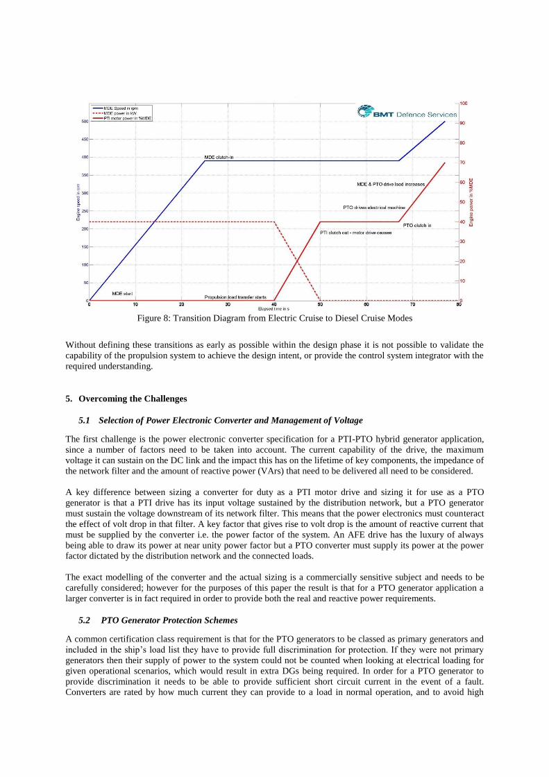
Figure 8: Transition Diagram from Electric Cruise to Diesel Cruise Modes
Without defining these transitions as early as possible within the design phase it is not possible to validate the
capability of the propulsion system to achieve the design intent, or provide the control system integrator with the
required understanding.
5. Overcoming the Challenges
5.1 Selection of Power Electronic Converter and Management of Voltage
The first challenge is the power electronic converter specification for a PTI-PTO hybrid generator application,
since a number of factors need to be taken into account. The current capability of the drive, the maximum
voltage it can sustain on the DC link and the impact this has on the lifetime of key components, the impedance of
the network filter and the amount of reactive power (VArs) that need to be delivered all need to be considered.
A key difference between sizing a converter for duty as a PTI motor drive and sizing it for use as a PTO
generator is that a PTI drive has its input voltage sustained by the distribution network, but a PTO generator
must sustain the voltage downstream of its network filter. This means that the power electronics must counteract
the effect of volt drop in that filter. A key factor that gives rise to volt drop is the amount of reactive current that
must be supplied by the converter i.e. the power factor of the system. An AFE drive has the luxury of always
being able to draw its power at near unity power factor but a PTO converter must supply its power at the power
factor dictated by the distribution network and the connected loads.
The exact modelling of the converter and the actual sizing is a commercially sensitive subject and needs to be
carefully considered; however for the purposes of this paper the result is that for a PTO generator application a
larger converter is in fact required in order to provide both the real and reactive power requirements.
5.2 PTO Generator Protection Schemes
A common certification class requirement is that for the PTO generators to be classed as primary generators and
included in the ship’s load list they have to provide full discrimination for protection. If they were not primary
generators then their supply of power to the system could not be counted when looking at electrical loading for
given operational scenarios, which would result in extra DGs being required. In order for a PTO generator to
provide discrimination it needs to be able to provide sufficient short circuit current in the event of a fault.
Converters are rated by how much current they can provide to a load in normal operation, and to avoid high

levels of thermal loading on the power electronic devices are typically very limited in terms of overload rating. A
conventional diesel-powered alternator, which has significant inertia and a high thermal mass, is capable of
transiently providing up to three times full load current (FLC) under a short circuit. Comparatively, a power
electronic converter has very limited overload capability since its thermal mass is much less, and beyond the
limit the controller will normally trip the converter to protect the devices.
An easy, although extreme, solution would be to simply install a (current) rating of converter three times larger
than is actually required. However this would not be practical nor would it make the hybrid option competitive in
terms of space, weight and cost to do this in order to meet the required overload. Instead a more refined solution
is needed that requires a thorough understanding of the issues. As previously discussed, it is usually necessary to
install a slightly larger converter for a PTO application compared to what could be used if it was only for PTI.
This assists in allowing the converter in providing fault current, due to the fact that some additional converter
(current) margin is already installed. The result is that whilst the PTO transient overload is still not as high as a
conventional alternator, it is greater than the baseline overload due to the extra installed capacity.
5.3 Blackstart Recovery
Another challenge is using the PTO generators for blackstart recovery operation, whereby the entire ship has lost
power and the hybrid system is used to restore power. This could be the case operationally if the DGs are
unavailable. The use of an induction machine causes a challenge when it comes to blackstart recovery as an
induction machine requires excitation voltage to be applied for magnetisation before it can produce power.
Normally when the hybrids become PTO generators this voltage can be simply provided by the converter which
is connected to a live distribution network (fed by the DGs). In a blackout situation this is not possible and so a
restart module is needed to connect to the hybrid converter.
The required restart module comprises of a small rectifier fed from the emergency switchboard connected
directly to the DC link of the hybrid converter. Figure 9 shows traces, with the main points marked, from actual
testing of the system at GE’s Marine Power Test Facility at Whetstone. The restart module initially energises the
DC link (Point A to Point B) so the machine bridge of the drive can provide sufficient volts to energise the
induction machine (the corresponding magnetisation current is shown at Point C). The hybrid machine will have
been driven by the main diesel engine (MDE) up to speed (the MDE fuel pumps are battery backup fed), and by
use of an encoder the machine bridge can synchronise its output to the rotating machine. Once this occurs active
power can be taken from the PTO generator and the machine bridge can boost the DC link to rated volts (Point
D), which allows the machine flux to be increased up to its nominal value (Point E to Point F). The process to
get the DC link and machine side up to rated volts takes approximately twelve seconds. Then all that is left is for
the network bridge of the drive to control the pre-charging of the network filter (not shown). Once these steps are
completed the main breaker is allowed to be closed, thus energising the distribution network and completing the
blackstart operation. This restart module has been successfully installed in both the MARS Fleet Tankers and
Norwegian LSV.

Figure 9: Trace of Black-Start Recovery Testing
5.4 Avoiding Hybrid Converter Trips
There is a history of converters protecting themselves from a faulty distribution network by tripping, however
this philosophy cannot be followed when the converter is acting as the power source (i.e. the PTO generator).
For example, there may exist a significant fault that causes a potential fault current greater than the hybrid
converter’s maximum overload capability. Conventionally in this situation the converter would trip and
shutdown requiring an operator to reset the controller and bring it back online – a potentially lengthy event, and
one that, depending on the current operational scenario, might have a major impact on the situation. A solution to
this has been developed using a technology transfer from the wind renewables application. The power system
network operator (the National Grid in the UK) set restrictions on when a converter for a wind-turbine is allowed
to trip – that is they have identified a range of grid faults through which the system must remain connected,
known as grid fault ride-through. To meet these requirements a process of current management has been applied
in the controller software code and this has now also been applied to the hybrid PTO marine application.
The exact methods of current management used are commercially sensitive; however as a high-level summary
the process works as follows: at all times the controller in the hybrid converter is monitoring the current being
produced. If a significant current is detected due to a short circuit or arcing event, the controller interrupts the
path of current, and prevents any further current rise. During this time, the fault can be cleared by the relevant
breaker opening using the normal protection scheme (the system will see some overcurrent and so the protection
devices will be able to respond). Once the relevant breaker has cleared the fault, the hybrid converter can quickly
resume providing power and normal system operation will be restored.
Figure 10 shows traces from actual testing of this concept at GE’s Marine Power Test Facility at Whetstone.
During this test a fault was created on the main bus to demonstrate the ride-through capability of the converter.
The traces shown compare the converter response with and without current management. On the left trace, the
standard configuration, when the fault is applied the main voltage rapidly collapses (Point 1) as the currents
spike to very high levels (Point 2). With current management applied, the right-hand trace, the main voltage
drops to zero (Point 3), and there is some current rise but it is managed (Point 4). During this time the breakers
are able to clear the fault, and then the volts can be quickly restored, all within approximately 250ms.
DB
E
A
F
C

Figure 10: Trace of Current Management Testing
6. Conclusions
This paper presents only a small selection of the observations and changes in approach that have been developed
relating to hybrid power & propulsion design projects. The intent of such work is to reduce and manage design
risk and ensure that the design solution developed and defined is resolved thoroughly against all the relevant
requirements and constraints in an effective manner.
A fundamental consideration which is of particular importance for Hybrid Power and Propulsion systems is the
Power and Propulsion Operating Philosophy. The operating philosophy ensures that all stakeholders a) gain a
common understanding of the overall requirements that drive the design solution and b) understand the
implications of meeting such requirements in the design from concept, to preliminary and through basic design
stages. Both of these key points help to ensure the Power and Propulsion solution remains valid and that
unjustifiable or excessive 'corner of the envelope' requirements are not able to drive the design solution unduly.
The second part of the paper demonstrates that to get the most out of a hybrid propulsion system, the concept
design needs to be tailored to meet the owner’s requirements and what is actually needed from the ship. Whilst
these new advanced hybrid systems are very flexible, the main benefits come when the complete system is fully
optimised and integrated to the platform. With the benefits come many challenges to the successful integration of
the hybrid system. The challenges addressed during the successful integration of recent projects have been
presented, and some of the lessons learnt discussed. The real-world examples cited demonstrate that the
challenges are varied and complex, often requiring careful trade-offs to optimise the solution.
Hybrid power & propulsion systems must be designed as a complete system combining the needs of propulsion,
ship’s service power supply and equipment type. Integration of the hybrid system as a whole is essential, and the
experience, skill and knowledge required to do this should not be underestimated.
7. Acknowledgements
The authors would like to thank Erwann Mauxion for leading the de-risking trials at GE’s Marine Power Test
Facility at Whetstone and providing the traces of the blackstart recovery and short circuit testing.
The views expressed in this paper are that of the authors and do not necessarily represent the views and opinions
of BMT Defence Services or GE Power Conversion.

8. References
Buckingham J.: “Hybrid Drives For Naval Auxiliary Vessels”, Proceedings of the Pacific 2013 Conference,
Sydney, Australia, October 7-9 2013.
Buckingham J.: “Ptool: Fast Performance Modelling of Marine Power & Propulsion Systems”, Proceedings of
the AES 2000 Conference, Paris, France, October 2000.
Buckingham J.: “Mapping the Hybrid Solution Space”, Proceedings of the Shipping in Changing Climates
Conference, Liverpool, United Kingdom, June 18-19 2014.
Couch T. & Fisher J.: “Power & Propulsion – Meeting the concept”, Proceedings of the International Naval
Engineering Conference 2016, Bristol, United Kingdom, April 26-28 2016.
Dalton T.C. & McCoy T.J.: “Naval Hybrid Propulsion Plant Design”, Proceedings of the International Naval
Engineering Conference 2012, Edinburgh, United Kingdom, May 15-17 2012.
Hodge C.G. & Mattick D.J.: “The Electric Warship Vol I-VI”, Transactions of the Institute of Marine Engineers
(Trans IMarE), 1995-2000.
Simmonds O.J.: “A History of Naval Electric Propulsion and Today’s Choices for New Vessels”, Proceedings of
the International Workshops, Conferences and Expo for Military and Marine Applications, Pune, India, May 18-
20 2013.
Simmonds O.J: “Advanced hybrid systems and new integration challenges”, Proceedings of the International
Naval Engineering Conference 2016, Bristol, United Kingdom, April 26-28 2016.