Medium Voltage Switchgear and Switches - moeller.kz Voltage Switchgear and Switches ... to IEC...
52
Medium Voltage Switchgear and Switches Medium Voltage Switchgear up to 17.5 kV, Air-insulated, metal-clad, withdrawable technique Type: AMC
Transcript of Medium Voltage Switchgear and Switches - moeller.kz Voltage Switchgear and Switches ... to IEC...

Medium Voltage Switchgear and Switches
Medium Voltage Switchgear up to 17.5 kV,Air-insulated, metal-clad,withdrawable technique
Type: AMC


CA⋅505⋅DE⋅0601
3
Medium-voltage switchgear up to 17.5 kV, air-insulated, metal-clad, withdrawable technique, Type AMC Index
Main features 4
Requirements 5Application examples 5Economic efficiency 5Reliability of supply 5Personnel safety 5
Panel structure 6Panel design 6Pressure relief 6Configuration of the drawer unit compartment 6Configuration of the busbar compartment 6Configuration of the cable connection compartment 6Configuration of low voltage compartment 6
Equipment 7Current and voltage transformers 7Capacitive voltage detection systems 7Door interlocking 7Cable installation 7Cable clamps 7Panel wiring 7
Panel configuration 8Basic panel structure 8
Key to type references 9Type reference key of panels 9Type reference key for AMC drawer units 9
Operation/interlocking 10Operation at the panel 10Interlocking system 10
Technical data/standards 11Technical data for AMC panels 11Standards 11
Panel delivery programme/equipment Delivery programme circuit-breaker panel 12Equipment for circuit-breaker panel 13
Delivery programme load-break switch panel 14Equipment for load-break switch panel 15
Delivery programme load-break switch panel with HRC fuse base 16Equipment for load-break switch panel with HRC fuse base 17
Delivery programme bus sectionaliser circuit-breaker panel 18Equipment for bus sectionaliser circuit-breaker panel 19
Delivery programme metering panel M1; sectionaliser panel 20Equipment for metering panel M1; sectionaliser panel 21
Delivery programme metering panel M5; with outgoing cables 22Equipment for metering panel M5; with outgoing cables 23
Delivery programme metering panel M6; busbar voltage measurement 24Equipment for metering panel M6; busbar voltage measurement 25
Delivery programme bus sectionaliser riser panel 26Equipment for bus sectionaliser riser panel 27
Delivery programme busbar riser panel; with cable connection 28Equipment for busbar riser panel; with cable connection 29
Delivery programme busbar earthing panel 30Equipment for busbar earthing panel 31
Delivery programme contactor panel 32Equipment for contactor panel 33
Drawer unit delivery programme/equipment Delivery programme vacuum circuit-breaker drawer unit 34Equipment for vacuum circuit-breaker drawer unit 35
Delivery programme vacuum load-break switch drawer unit 36Equipment for vacuum load-break switchdrawer unit 37
Delivery programme disconnecting link drawer unit 38Equipment for disconnecting link drawer unit 39
Delivery programme vacuum contactor drawer unit 40Equipment for vacuum contactor drawer unit 41
Delivery programme earthing switch 42Earthing switch, type EDL 42Earthing switch type DES 42Equipment for earthing switch 43
Installation in the switchgear room 44Operating premises and intended use 44Equipment installation in the switchgear room 44Personnel safety 44
Vacuum circuit-breaker 45Type NVL vacuum circuit-breaker 45Switch poles 45Switch mechanism 45
Capacitive voltage detection system 46Capacitive voltage detection system 46
Switchgear accessories 47Busbar earthing drawer unit 47Auxiliary carriage 47Operating levers 47
Configuration examples of protection and control systems 48

CA⋅505⋅GB⋅0601
4
Medium-voltage switchgear up to 17.5 kV, air-insulated, metal-clad, withdrawable technique, Type AMCMain features
Main features
AMC (Air-insulated Metal Clad) panels are type-tested, air-insulated, metal-clad units which can be assembled side-by-side.
Ormazabal AMC switchgear assemblies satisfy the international requirements for air-insulated metal-clad switchgear assemblies.
Switchgear in withdrawable technique
Four metal-clad compartments
Drawer units with vacuum circuit-breaker
Drawer units with vacuum load-break switch
Drawer units with vacuum contactor
Standard current and voltage transformers
All standard types of protection and control systems can be used
Suitable for combined protection and control systems, as well as for inclusion in network control systems
Cable connection compartment with separate access door at the front and clamps for up to 6 cables per phase
High reliability
High security of supply
Maximum personnel safety
High operator safety
Low-maintenance switchgear
Simple and clear operation
Options for customer-specific equipment
Simple and robust design
Easy-to-install panel structure

CA⋅505⋅GB⋅0601
Medium-voltage switchgear up to 17.5 kV, air-insulated, metal-clad, withdrawable technique, Type AMC Requirements
5
Requirements
Economic efficiency
The flexibility of the standardised AMC switchgear with its options for configuration to customer requirements allows it to be functionally matched to its application. The panels can be extended or modified at a later date after installation. The grouped panels can be extended on either side without modification to the existing installation.
Reliability of supply
The high quality of AMC switchgear with separate compartments for busbars, switchgear and cable connections ensures a high degree of reliability in operation and supply for the application. Thus, for instance, cables can be checked or switchgear exchanged without switching off the busbars, with the overall equipment remaining in operation. The drawer unit design allows the operating parts of the equipment to be restored to availability within the shortest possible time.
Personnel safety
In general all switching operations are performed with closed panel doors.The panels have been tested for arc faults according toIEC 62271-200 and thus satisfy the international standards for the personnel safety in the event of an internal fault.Metal doors, shields and positively actuated shutters in the drawer unit compartment protect against unintentional touching of energised parts.An extensive interlocking system for the switchgear and the panel offers the operator additional protection against incorrect actuation.Voltage testing in the individual compartments can optionally be performed using capacitive systems to IEC 61243-5. This can be done without opening the compartment doors.
Application examples
AMC switchgear is suitable for use in switching stations for power generation and power distribution for:
• Utility companies• Combined heat and power stations• Power distribution at buildings• Steel industry• Heavy industry• Airport power distribution systems• Automotive industry• Chemical industry• Petro-chemical industry• Food industry• Main distribution substations• Shipbuilding• Stand-by generating supplies
Application example in the chemical industry

CA⋅505⋅GB⋅0601
6
Medium-voltage switchgear up to 17.5 kV, air-insulated, metal-clad, withdrawable technique, Type AMCPanel structure
Panel structure
Panel design
AMC switchgear is characterised by its type-tested panels which can be extended on either side. The interior structure is divided into three medium-voltage metal-clad compartments.
A = drawer unit compartmentB = busbar compartmentC = cable connection compartment
The low voltage compartment (relay enclosure) is arranged as a separate module partitioned with sheet-metal and can optionally be supplied at various heights. To facilitate transport into the switchgear room, the low voltage compartment can be detached from the switchgear panel. Connections between the panels are brought through the sheet-metal by insulated cast resin bushings.The cabinets are made of galvanized sheet steel in a solid, distortion-resistant construction. The panel doors are powder-coated in RAL7035. The several abscission, insulation and operating components are bolted or riveted to the panels depending on the requirements.The panel front has separate compartment doors hinged on the right for the drawer unit compartment, cable connection compartment and low voltage compartment. The door opening angle is restricted to about 150 degrees to ensure the means of escape.An existing installation can be extended on both sides using factory-built standard units.
Pressure relief
All medium voltage metal-clad compartments have separate pressure relief facilities. In the standard version, the pressure relief from the switchgear panel is directed upwards. Depending on the application and the switchgear building pressure relief facilities, arc absorber assemblies for pressure reduction can be fitted instead of pressure relief flaps; or a pressure relief channel can be mounted, which can be arranged panel-wise with lateral connecting flange depending on the design of the panel. A closed panel floor is an essential feature of the type-tested standard equipment.
Configuration of the drawer unit compartment
Depending on the panel type, the drawer unit compartment can be equipped with the following units:
• Vacuum circuit-breaker• Vacuum load-break switch• Vacuum contactor (incl. HRC fuse base)• Disconnecting link• Busbar earthing switch
Positively actuated metal shutters protect against unintentional touching of the fixed contacts when the drawer unit is in the disconnected position. An auxiliary carriage is available for taking out and inserting the drawer unit; the carriage is interlocked with the panel while handling.
Mechanical actuation of the switches and operation of the drawer units when the metal-clad compartment is closed is provided by actuating controls at the compartment door.
Optional motorised drives for the switches and the drawer movement are available so that fully remote control can be implemented. Optionally, in the metering panel current and voltage transformers according to DIN 42600 part 8 respectively part 9 can be fixed mounted instead of the drawer unit. In the bus sectionaliser riser panel versions the compartment can remain unequipped without bushings and shutters.
Configuration of the busbar compartment
The busbar compartment is equipped with flat copper busbars sized according to the panel rating. The busbars can be linked from panel to panel. Inside, the busbars are mounted phase-wise on insulators, so that panels can be easily and quickly assembled into a row. The busbar supports can optionally be assembled with a capacitive system for voltage measuring according to IEC 61243-5. The partitioning of the busbar compartment is provided with bushings for panel-to-panel connections.
Configuration of the cable connection compartment
The cable connection compartment offers a multitude of standard and customer option equipment with:
• Current and voltage transformers• Voltage transformers with primary fuses• Earthing switch• Surge arrestor• Three-phase medium voltage capacitor• HRC fuse base
Depending on the panel version up to three cable systems per phase can be connected in AMC6 panels and up to six cable systems per phase in AMC9 panels. The panel floor is sheet-metal. In the bus sectionaliser panel versions, the compartment contains the section busbars. For connections through the side, flat profile copper busbars are used as in the busbar compartment. Inside, the busbars are mounted phase-wise on insulators, so that panels can be easily and quickly assembled into a row. Optionally, a capacitive system for voltage measuring according to IEC 61243-5 can be mounted in the busbar compartment.
Configuration of low voltage compartment (relay enclosure)
The low voltage compartment is designed as a separate assembly and can be removed from the switchgear panel. The configuration with protection and control systems is arranged functionally for the respective application. Application-related standards such as those for outgoing panels with overcurrent protection, differential protection, motor protection etc. provide a secure project planning basis for the consultant. All usual protection and control systems can be assembled. Also equipment supplied by the customer can be used.

CA⋅505⋅GB⋅0601
Medium-voltage switchgear up to 17.5 kV, air-insulated, metal-clad, withdrawable technique, Type AMC Equipment
7
Equipment
Current and voltage transformers
For configurations with current and voltage transformers, Ormazabal use proven international technology. As standard, current and voltage transformers according to DIN 42600, parts 8 and 9, and IEC 60044-1 will be mounted. In addition, because of the multitude of installation options in the cable connection area, a wide variety of transformers supplied by the customer can be used. The current and voltage transformers are mounted as separate assemblies, irrespective to the basic panel design and functional elements such as the contact systems for the drawer units and earthing switches. Depending on the panel equipment and type, they can be exchanged, protected by the metal partitioning, even while operating busbar compartment. The standards and generally recognised technical rules (IEC standards, DIN standards, VDE regulations) for working on medium voltage installations must be observed.
Capacitive voltage detection systems
The optional capacitive voltage detection system according to IEC 61243-5 is mounted in the cable connection and/or busbar compartment of the panel. It is assembled irrespective of the basic panel design and func-tional elements. It can be exchanged under the same conditions as previously described for the current and voltage transformers.
Door interlocking
The doors can optionally be equipped with mechanical and electro-mechanical interlocking.
Cable installation
The medium voltage cables can be installed from the front of the panel. The cable connection compartment is easily accessible and has a separate compartment door. After the drawer unit has been removed out of the panel, the front cross-spar of the panel and the plate between the drawer unit compartment and cable connection compartment can be removed with a few movements, for additional ease of installation of cables in the cable connection compartment.The maximum cable cross-sections that can be attached at the cable connections at the panels are as follows:
AMC6 = maximum 3 single-core cables 240 mm2 per phase
AMC9 = maximum 6 single-core cables 500 mm2 per phase
The panel floor comprises of split sheet metal modules with reducing rings for sealing the incoming cables.
Cable clamps
The short circuit-proof cable mountings in the switchgear panel are provided in the cable connection compartment by means of cable fixing irons and cable clamps. There are two cable clamp sizes available for installation.
Size 1Cable clamping range for single-core cables 26 to 38 mm diameter
Size 2Cable clamping range for single-core cables 36 to 49 mm diameter
Panel wiring
Control wiring within the panels is installed in generously-propor-tioned metal wiring ducts, which are easily accessible to the left and right of the front interior of the panel. In all panel variants the left wiring duct extends from the panel floor up to the low voltage compartment, enabling separate wiring possibilities for each switchgear panel. Additionally, in the low voltage compartment area there are side openings which allow connections from panel to panel to a loop wiring system.
Panel type AMC9-12/2500-2500/31-L cable connection area with 6x1x500mm2 per phase and capacitive insulators
Standard voltage transformers DIN 42600 part 9, front mounted

CA⋅505⋅GB⋅0601
8
Medium-voltage switchgear up to 17.5 kV, air-insulated, metal-clad, withdrawable technique, Type AMCPanel configuration
Panel configuration
Basic panel structure (configuration example)
Low voltage compartment door (front cover)
Low voltage compartment door (application-specific)
Door closing
Capacitive voltage detection system (optional)
Low voltage compartment door handles
Drawer unit compartment door
Operation opening for manual winding up of spring accumulator
Manual operation of switch
Viewing window - switch indicators
Manual operation of switch
Slide for the operation opening
Operation opening for drawer unit
Drawer unit compartment door handles
Louvres
Manual operation of earthing switch
Cable connection compartment door
Cable connection compartment door handles
Cable connection compartment pressure relief channel
Busbar support insulator (optional capacitive voltage detection system)
Main and outgoing busbars
Panel fixed contacts
Current transformers
Voltage transformers
Cable terminations
Cable fixing irons
Busbar / drawer unit compartment insulating bushings
Automatic metal shutters
Switch low voltage connector
Switch contact system
Switch drawer unit
Cable connection / drawer unit compartment insulating bushings
Earthing switch with manual actuator (optional motorised driving mechanism)
Outgoing cable support insulator (optional capacitive voltage detection system)
Wiring duct
Earthing busbar
A - drawer unit compartmentB - busbar compartmentC - cable connection compartmentD - low voltage compartment
rearmounted
frontmounted

CA⋅505⋅GB⋅0601
Medium-voltage switchgear up to 17.5 kV, air-insulated, metal-clad, withdrawable technique, Type AMC Key to type references
9
Key to type references
Type reference key of panels1)
AMC → (Air-insulated Metal Clad) panels can be equipped with a wide variety of standardised customer options. The panel types are differentiated in their widths, ratings and principal functions.
Example : AMC6-12/1250-630/25-L
1) Range of individual panel types and their main components → pages 12 to 33.2) Assignment of drawer units → pages 34 to 41.3) For vacuum load-break switches and disconnecting links the rated short-time withstand
current is stated.4) For rated voltage 17.5 kV the rated current is 2000 A
Type reference key for AMC drawer units2)
The AMC drawer units differ depending on the type of equipment and its technical rated values.
Example : NVL2F-12/25/1250-150C
Panel width: 6 = 650 mm9 = 900 mm
Rated voltage: 7 = 7.2 kV12 = 12 kV17 = 17.5 kV
Rated busbar current: 630 A1250 A2500 A4)
Rated current of outgoing busbar:
200 A630 A
1250 A2500 A4)
Rated short-time withstand current:
20 = 20 kA25 = 25 kA31 = 31.5 kA
Principal functions: L = Circuit-breaker panelLG = Bus sectionaliser circuit-breaker panelK = Load break switch panelT = Load break switch panel with
HRC fuse baseM1= Metering panel, sectionaliser panelM5= Metering panel with outgoing cablesM6= Metering panel, busbar voltage
measurementH = Busbar riser panel with cable connectionHG = Bus sectionaliser riser panelE = Busbar earthing panelS = Contactor panel
AMC. .. .-. . . ./. . . . .-. . . . ./. . . .-. . . .
Type of equipment:
VL = Vacuum circuit-breakerVLT = Vacuum load-break switchVS = Vacuum contactorTB = Disconnecting link
Type of insulating enclosure: 2, 3
Rated voltage: 7 = 7.2 kV12 = 12 kV17= 17.5 kV
Rated short-circuit breaking current3):
20 = 20 kA25 = 25 kA31 = 31.5 kA
Rated current: 200 A630 A
1250 A2500 A4)
Distance between pole centres:
150 mm210 mm
N. . . . . F-. . . ./. . . ./. . . . .-. . . .-C

CA⋅505⋅GB⋅0601
10
Medium-voltage switchgear up to 17.5 kV, air-insulated, metal-clad, withdrawable technique, Type AMCOperation/interlocking
Operation/interlocking
Operation at the panel
To ensure quick and reliable operation of the panel, the operating and display elements are positioned for clear viewing and for clear association. Capacitive voltage detection systems for the outgoing cables and/or main busbars can be equipped as options.
Interlocking system
The interlocking of panel components according to VDE 0671 part 200 respectively IEC 62271-200 and optional additional interlocking features of type AMC panels, in connection with the metal-clad panel design, form a safe system and also assist the operator in performance of his operations. The following mechanical interlocking is provided:
• The drawer unit with the switch can be moved only when the switch and the earthing switch in the panel are switched off.
• The switch can only be switched when the drawer unit is either in the disconnected position or the connected position.
• The drawer unit can be moved only if the low-voltage plug for the auxiliary circuits and the control circuits is plugged in and interlocked.
• The low voltage plug for connecting the auxiliary circuit and the control circuits can only be unplugged from the switch when the drawer unit is in the disconnected position.
• The drawer unit can be moved from the disconnected position only when the interlock between drawer unit and panel is active.
• Once the drawer unit has moved away from the disconnected position, the interlocking between drawer unit and panel cannot be released.
• The switch at the drawer unit is not switchable whilst the drawer is moving to the end positions.
• The manual crank for moving the drawer unit can be inserted or removed only when the drawer unit is either in the disconnected position or the connected position.
• The earthing switch in the panel frame can be switched only when the drawer unit in is the disconnected position or has been removed completely out of the panel.
• Once the earthing switch is connected, the drawer unit cannot move from the disconnected position to the connected position.
• The manual crank for moving the drawer units can be inserted or removed only when the panel door is closed.
Optional interlockings:
• The drawer unit compartment door can be opened only when the drawer unit is in the disconnected position.
• The cable connection compartment door can be opened only if the earthing switch is connected.
Circuit-breaker panel with operator interface
Operating and display elements (panel controls) with integrated protection system
Capacitive voltage detection system
Low voltage compartment door handles
Switch operation, mechanical ON - OFF
Switch status indication, mechanical ON - OFF, Operating spring charged - discharged
Operation opening for manual winding up of spring accumulator
Operation opening for drawer unit crank handle
Drawer unit compartment door handles
Driving mechanism – earthing switch with mechanical position indicator
Cable connection compartment door handles
Cable connection compartment door interlocking
Drawer unit compartment door interlocking
Twist handle for manual operation of the switch

CA⋅505⋅GB⋅0601
1
Medium-voltage switchgear up to 17.5 kV, air-insulated, metal-clad, withdrawable technique, Type AMC Technical data/standards
1
Technical data/standards
Technical data for AMC panels
Standards
AMC panels satisfy the listed VDE standards and IEC publications:
Rated voltage Ur [kV]
7.2 12 17.5
Rated frequency fr Hz 50/60 50/60 50/60
Rated lightning impulse withstand voltage Up kV 60 75 95
Rated power-frequency withstand voltage Ud kV 20 28 38
Rated normal current Ir ss
for busbarsOptional A 630 630 630
A 1250 1250 1250
A 2500 2500 2000
Rated normal current Ir
for outgoing busbarsOptional1) A 630 630 630
A 1250 1250 1250
A 2500 2500 2000
Rated short-time withstand current Ik
with tk = 3 sOptional kA 20 20 20
kA 25 25 25
kA 31.5 31.5 31.5
Rated peak withstand current IP
at fr = 50 HzkA 50 50 50
kA 62.5 62.5 62.5
kA 80 80 80
Ambient temperature T °C -5 to +40
Average measured over 24 h maximum °C +35
Relative humidity
Average measured over 24 h maximum % 95
Average measured over 1 month maximum % 90
Altitude maximum m 1000
Arc-fault qualification up to IAC AFL 31.5 kA 1 s
Operating availability category LSC2B
Compartmentalisation class PM
Degree of Protection of the external enclosure IP4X
Panel door colour (standard) RAL 7035
1) Rated normal current for outgoing busbars
Load-break switch panel = 630 A
Load-break panel / metering panel with HRC fuse base
= 200 A; rated short-time withstand current Ik limited by HRC fuses
Vacuum contactor panel = 200 A continuously rated load, detailed selection page 32;Rated short-time withstand current Ik limited by HRC fuses
DIN VDE 0671 Part 200 IEC publication 62271-200
DIN VDE 0670 Part 1000 IEC publication 60694
IEC publication 62271-100
IEC publication 62271-102

CA⋅505⋅GB⋅0601
12
Medium-voltage switchgear up to 17.5 kV, air-insulated, metal-clad, withdrawable technique, Type AMCDelivery programme circuit-breaker panel
Panel ranges/equipmentDelivery programme circuit-breaker panel
Technical data and dimensions2):
Configuration example for panel type ...-L Other equipment options → page 13.
Rated voltage Ur [kV]
7.2 12 17.5
Rated normal current Ir
for outgoing busbarsA 630 630 630
A 1250 1250 1250
A 2500 2500 2000
Panel height
Standard incl. arc-deflecting shield
mm 2700 2700 2700
with pressure relief channel mm 2900 2900 2900
Panel depth
mm 1400 1400 1400
Panel width for Ir
ï 1250 A mm 650/900
650/900
650/900
> 1250 A up to 2500 A mm 900 900 900
2) Additional technical data → pages 9 and 11.
�
���
�
��
Panel types1) Rated voltage Ur [kV]
7.2 12 17.5AMC6-12/630-630/20-L • •AMC6-12/1250-630/20-L • •AMC6-12/1250-1250/20-L • •AMC6-12/2500-630/20-L • •AMC6-12/2500-1250/20-L • •AMC6-12/630-630/25-L • •AMC6-12/1250-630/25-L • •AMC6-12/1250-1250/25-L • •AMC6-12/2500-630/25-L • •AMC6-12/2500-1250/25-L • •AMC6-12/630-630/31-L • •AMC6-12/1250-630/31-L • •AMC6-12/1250-1250/31-L • •AMC6-12/2500-630/31-L • •AMC6-12/2500-1250/31-L • •AMC9-12/630-630/20-L • •AMC9-12/1250-630/20-L • •AMC9-12/1250-1250/20-L • •AMC9-12/2500-630/20-L • •AMC9-12/2500-1250/20-L • •AMC9-12/2500-2500/20-L • •AMC9-12/630-630/25-L • •AMC9-12/1250-630/25-L • •AMC9-12/1250-1250/25-L • •AMC9-12/2500-630/25-L • •AMC9-12/2500-1250/25-L • •AMC9-12/2500-2500/25-L • •AMC9-12/630-630/31-L • •AMC9-12/1250-630/31-L • •AMC9-12/1250-1250/31-L • •AMC9-12/2500-630/31-L • •AMC9-12/2500-1250/31-L • •AMC9-12/2500-2500/31-L • •AMC6-17/630-630/20-L •AMC6-17/1250-630/20-L •AMC6-17/1250-1250/20-L •AMC6-17/2000-630/20-L •AMC6-17/2000-1250/20-L •AMC6-17/630-630/25-L •AMC6-17/1250-630/25-L •AMC6-17/1250-1250/25-L •AMC6-17/2000-630/25-L •AMC6-17/2000-1250/25-L •AMC6-17/630-630/31-L •AMC6-17/1250-630/31-L •AMC6-17/1250-1250/31-L •AMC6-17/2000-630/31-L •AMC6-17/2000-1250/31-L •AMC9-17/630-630/20-L •AMC9-17/1250-630/20-L •AMC9-17/1250-1250/20-L •AMC9-17/2000-630/20-L •AMC9-17/2000-1250/20-L •AMC9-17/2000-2000/20-L •AMC9-17/630-630/25-L •AMC9-17/1250-630/25-L •AMC9-17/1250-1250/25-L •AMC9-17/2000-630/25-L •AMC9-17/2000-1250/25-L •AMC9-17/2000-2000/25-L •AMC9-17/630-630/31-L •AMC9-17/1250-630/31-L •AMC9-17/1250-1250/31-L •AMC9-17/2000-630/31-L •AMC9-17/2000-1250/31-L •AMC9-17/2000-2000/31-L •1) Key to type references → page 9.

CA⋅505⋅GB⋅0601
3
Medium-voltage switchgear up to 17.5 kV, air-insulated, metal-clad, withdrawable technique, Type AMC Equipment for circuit-breaker panel
1
Customer-specific current and voltage transformers:
Ratings:
................................................................................................................
................................................................................................................
................................................................................................................1) Mounting positions for equipment → page 8
Only one equipment variant can be assembled at each mounting position.2) Equipment of switch → pages 34 and 353) Only one cable connection per phase possible4) Necessary for MV motor and generator applications 5) Equipment of earthing switch → pages 42 and 436) Not possible when panel cover above option pressure relief channel is used
Equipment for circuit-breaker panelEquipment options for AMC circuit-breaker panels Type: AMC...-...../........-......../.....-L
Example : AMC6-12/1250-630/25-L
Low-voltage compartment1):❑ height 600 mm (standard)❑ height 800 mm❑ door with padlock interlocking
Busbar compartment1):❑ busbars 630 A❑ busbars 1250 A❑ busbars 2500 A❑ capacitive voltage detection system at busbars
Cable connection compartment1):❑ outgoing busbars 630 A❑ outgoing busbars 1250 A❑ outgoing busbars 2500 A (only at panel width 900 mm)❑ support current transformer 1 core❑ support current transformer 2 cores❑ support current transformer 3 cores❑ voltage transformer single phase, 1 winding, rear mounted❑ voltage transformer single phase, 2 windings, rear mounted❑ voltage transformer single phase, 3 windings, rear mounted❑ voltage measurement before current measurement, rear mounted❑ voltage measurement after current measurement, rear mounted❑ fixed compensation 3ph up to 133 kVAR, 7.2 kV; up to 100 kVAR, 12 kV 3)
❑ earthing switch5), manual operation❑ earthing switch5), manual operation with electro-mechanical interlocking❑ earthing switch with motorised drive5)
❑ voltage transformer single phase, 1 winding, front mounted❑ voltage transformer single phase, 2 windings, front mounted❑ voltage transformer single phase, 1 winding,
with primary fuse up to 10 kV, front mounted❑ voltage transformer single phase, 2 windings,
with primary fuse up to 10 kV, front mounted❑ surge arrestor up to 10 kV at outgoing, front mounted4)
❑ cable connection 1 system per phase❑ cable connection 2 systems per phase❑ cable connection 3 systems per phase❑ cable connection 4 systems per phase (only at panel width 900 mm)❑ cable connection 5 systems per phase (only at panel width 900 mm)❑ cable connection 6 systems per phase (only at panel width 900 mm)❑ cable lug termination M12❑ cable lug termination M16❑ cable clamp size 1 (→ page 7)❑ cable clamp size 2 (→ page 7)❑ ball terminal bolt 25 mm, L1-L3 and panel fixing point for earthing❑ door with padlock interlocking❑ door interlocking by earthing switch❑ door interlocking electro-mechanical.❑ capacitive voltage detection system at outgoing cable
Panel extension above1) 6):❑ busbar voltage transformer single phase up to 10 kV,
1 winding; up to 25 kA (only at panel width 650 mm)❑ busbar voltage transformer single phase up to 10 kV,
2 windings; up to 25 kA (only at panel width 650 mm)❑ busbar earthing switch5) up to 10 kV, 25 kA, manual operation;
(only at panel width 650 mm)❑ busbar earthing switch5) up to 10 kV, 25 kA, manual operation with
electro-mechanical. interlocking; (only at panel width 650 mm)❑ surge arrestor at busbars up to 10 kV, 25 kA (only at panel width 650 mm)❑ arc absorber assembly (standard equipment for AMC9)
Drawer unit compartment1):❑ vacuum circuit-breaker 630 A2)
❑ vacuum circuit-breaker 630 A with motorised drive2)
❑ vacuum circuit-breaker 1250 A2)
❑ vacuum circuit-breaker 1250 A with motorised drive2)
❑ vacuum circuit-breaker 2500 A(only at panel width 900 mm) 2)
❑ vacuum circuit-breaker 2500 A with motorised drive (only at panel width 900 mm) 2)
❑ panel connection bolt M16 for earthing drawer unit / manual❑ door with manual switch operation❑ door with manual switch operation, padlock interlocking❑ door without operation opening❑ door with padlock interlocking❑ door interlocking with drawer unit position, mechanical❑ door interlocking electro-mechanical❑ drawer unit with mechanical interlocking to the earthing switch❑ drawer unit with mechanical interlocking to the earthing switch
and motorised drive for drawer movement❑ drawer unit with mechanical interlocking to the earthing switch
and electro-mechanical interlocking to the drawer movement
Panel covers above1): ❑ arc-deflecting shield 500 mm (standard)❑ pressure relief channel in panel partition (panel height 2900 mm)
without channel from the switchgear room
Standard protection and control system:❑ panel control system with integral directional time overcurrent protection ❑ panel control system with integral cable differential protection❑ panel control system with integral transformer differential protection❑ standard control circuit with time overcurrent protection❑ standard control circuit with directional time overcurrent protection❑ customer-specific protection and control systems
Auxiliary voltages for motorised drives, electro-mechanicalinterlocking and controls:❑ 24 V DC❑ 48 V DC❑ 60 V DC❑ 110 V DC❑ 220 V DC❑ 110 V AC❑ 230 V AC

CA⋅505⋅GB⋅0601
14
Medium-voltage switchgear up to 17.5 kV, air-insulated, metal-clad, withdrawable technique, Type AMCDelivery programme load-break switch panel
Delivery programme load-break switch panel
Technical data and dimensions2):
Configuration example for panel type ...-K Other equipment options → page 15.
Rated voltage Ur [kV]
7.2 12 17.5
Rated normal current Ir
for outgoing busbarsA 630 630 630
Panel height
Standard incl. arc-deflecting shield
mm 2700 2700 2700
with pressure relief channel mm 2900 2900 2900
Panel depth
mm 1400 1400 1400
Panel width for Ir
630 A mm 650 650 650
2) Additional technical data → pages 9 and 11.
�
���
�
��
Panel types1) Rated voltage Ur [kV]
7.2 12 17.5AMC6-12/630-630/20-K • •AMC6-12/1250-630/20-K • •AMC6-12/2500-630/20-K • •AMC6-12/630-630/25-K • •AMC6-12/1250-630/25-K • •AMC6-12/2500-630/25-K • •AMC6-17/630-630/20-K •AMC6-17/1250-630/20-K •AMC6-17/2000-630/20-K •AMC6-17/630-630/25-K •AMC6-17/1250-630/25-K •AMC6-17/2000-630/25-K •1) Key to type references → page 9.

CA⋅505⋅GB⋅0601
5
Medium-voltage switchgear up to 17.5 kV, air-insulated, metal-clad, withdrawable technique, Type AMC Equipment for load-break switch panel
1
Customer-specific current and voltage transformers:
Ratings:
................................................................................................................
................................................................................................................
................................................................................................................1) Mounting positions for equipment → page 8
Only one equipment variant can be assembled at each mounting position.2) Equipment of switch → pages 36 and 373) Only one cable connection per phase possible4) Equipment of earthing switch → pages 42 and 435) Not possible when panel cover above option pressure relief channel is used
Equipment for load-break switch panelEquipment options for AMC load-break switch panels Type: AMC6-...../........-630/.....-K
Example : AMC6-12/1250-630/20-K
Low-voltage compartment1):❑ height 600 mm (standard)❑ height 800 mm❑ door with padlock interlocking
Busbar compartment1):❑ busbars 630 A❑ busbars 1250 A❑ busbars 2500 A❑ capacitive voltage detection system at busbars
Cable connection compartment1):❑ support current transformer 1 core❑ support current transformer 2 cores❑ support current transformer 3 cores❑ voltage transformer single phase, 1 winding, rear mounted❑ voltage transformer single phase, 2 windings, rear mounted❑ voltage transformer single phase, 3 windings, rear mounted❑ voltage measurement before current measurement, rear mounted❑ voltage measurement after current measurement, rear mounted❑ fixed compensation 3ph up to 133 kVAR, 7.2 kV; up to 100 kVAR, 12 kV 3)
❑ earthing switch4), manual operation❑ earthing switch4), manual operation with electro-mechanical interlocking❑ earthing switch with motorised drive4)
❑ voltage transformer single phase, 1 winding, front mounted❑ voltage transformer single phase, 2 windings, front mounted❑ voltage transformer single phase, 1 winding,
with primary fuse up to 10 kV, front mounted❑ voltage transformer single phase, 2 windings,
with primary fuse up to 10 kV, front mounted❑ surge arrestor up to 10 kV at outgoing, front mounted❑ cable connection 1 system per phase❑ cable connection 2 systems per phase❑ cable connection 3 systems per phase❑ cable lug termination M12❑ cable lug termination M16❑ cable clamp size 1 (→ page 7)❑ cable clamp size 2 (→ page 7)❑ ball terminal bolt 25 mm, L1-L3 and panel fixing point for earthing❑ door with padlock interlocking❑ door interlocking by earthing switch❑ door interlocking electro-mechanical.❑ capacitive voltage detection system at outgoing cable
Panel extension above1) 5):❑ busbar voltage transformer single phase up to 10 kV, 1 winding; up to 25 kA ❑ busbar voltage transformer single phase up to 10 kV, 2 windings; up to 25 kA❑ busbar earthing switch4) up to 10 kV, 25 kA, manual operation ❑ busbar earthing switch4) up to 10 kV, 25 kA, manual operation with
electro-mechanical interlocking❑ surge arrestor at busbars up to 10 kV, 25 kA ❑ arc absorber assembly
Drawer unit compartment1):❑ vacuum circuit-breaker 630 A2)
❑ Panel connection bolt M16 for earthing drawer unit / manual❑ door with manual switch operation❑ door with manual switch operation, padlock interlocking❑ door without operation opening❑ door with padlock interlocking❑ door interlocking with drawer unit position, mechanical❑ door interlocking electro-mechanical❑ drawer unit with mechanical interlocking to the earthing switch❑ drawer unit with mechanical interlocking to the earthing switch and motorised
drive for drawer movement❑ drawer unit with mechanical interlocking to the earthing switch and
electro-mechanical interlocking to the drawer movement
Panel covers above1): ❑ arc-deflecting shield 500 mm (standard)❑ pressure relief channel in panel partition (panel height 2900 mm)
without channel from the switchgear room
Standard protection and control system:❑ panel control system ❑ standard control circuit❑ customer-specific control circuit
Auxiliary voltages for motorised drives, electro-mechanical interlocking and controls:❑ 24 V DC❑ 48 V DC❑ 60 V DC❑ 110 V DC❑ 220 V DC❑ 110 V AC❑ 230 V AC

CA⋅505⋅GB⋅0601
16
Medium-voltage switchgear up to 17.5 kV, air-insulated, metal-clad, withdrawable technique, Type AMCDelivery programme load-break switch panel with HRC fuse base
Delivery programme load-break switch panel with HRC fuse base
Technical data and dimensions2):
The rated short-time withstand current Ik at the outgoing busbars is limited by the HRC fuses.The three-phase tripping of the load-break switch (optional) is performed electrically by the auxiliary contacts of the fuse base and the load-break switch trip element.
At HRC fuse base high voltage fuses according to DIN 43625 and IEC 60282-1, dimension e = 292 mm, d = up to 85 mm can be implemented.
Configuration example for panel type ...-TOther equipment options → page 17.
Rated voltage Ur [kV]
7.2 12
Rated normal current Ir
for outgoing busbarsA 200 200
Panel height
Standard incl. arc-deflecting shield
mm 2700 2700
with pressure relief channel mm 2900 2900
Panel depth
mm 1400 1400
Panel width for Ir
200 A mm 650 650
2) Additional technical data → pages 9 and 11.
�
���
�
��
Panel types1) Rated voltage Ur [kV]
7.2 12AMC6-12/630-200/20-T • •AMC6-12/1250-200/20-T • •AMC6-12/2500-200/20-T • •AMC6-12/630-200/25-T • •AMC6-12/1250-200/25-T • •AMC6-12/2500-200/25-T • •AMC6-12/630-200/31-T • •AMC6-12/1250-200/31-T • •AMC6-12/2500-200/31-T • •1) Key to type references → page 9.

CA⋅505⋅GB⋅0601
7
Medium-voltage switchgear up to 17.5 kV, air-insulated, metal-clad, withdrawable technique, Type AMC Equipment for load-break switch panel with HRC fuse base
1
Customer-specific current and voltage transformers:
Ratings:
................................................................................................................
................................................................................................................
................................................................................................................1) Mounting positions for equipment → page 8
Only one equipment variant can be assembled at each mounting position.2) Equipment of switch → pages 36 and 373) Equipment of earthing switch → pages 42 and 434) Not possible when panel cover above option pressure relief channel is used
Equipment for load-break switch panel with HRC fuse baseEquipment options for AMC - load-break switch panels with HRC fuse base Type: AMC6-12/........-200/.....-T
Example: AMC6-12/1250-200/25-T
Low-voltage compartment1):❑ height 600 mm (standard)❑ height 800 mm❑ door with padlock interlocking
Busbar compartment1):❑ busbars 630 A❑ busbars 1250 A❑ busbars 2500 A❑ capacitive voltage detection system at busbars
Cable connection compartment1):❑ support current transformer 1 core❑ support current transformer 2 cores❑ support current transformer 3 cores❑ voltage transformer single phase, 1 winding, rear mounted❑ voltage transformer single phase, 2 windings, rear mounted❑ voltage transformer single phase, 3 windings, rear mounted❑ voltage measurement before current measurement❑ voltage measurement after current measurement❑ HRC fuse base 3ph with auxiliary contacts 1NO + 1NC for tripping
or indication for HRC fuses e = 292 mm, d = up to 85 mm❑ earthing switch3), manual operation❑ earthing switch3), manual operation with electro-mechanical interlocking❑ earthing switch with motorised drive3)
❑ surge arrestor up to 10 kV at outgoing, front mounted❑ cable connection 1 system per phase❑ cable lug termination M12❑ cable clamp size 1 (→ page 7) ❑ door with padlock interlocking❑ door interlocking by earthing switch❑ door interlocking electro-mechanical.❑ capacitive voltage detection system at outgoing cable
Panel extension above1) 4):❑ busbar voltage transformer single phase up to 10 kV, 1 winding; up to 25 kA ❑ busbar voltage transformer single phase up to 10 kV, 2 windings; up to 25 kA❑ busbar earthing switch3) up to 10 kV, 25 kA, manual operation ❑ busbar earthing switch3) up to 10 kV, 25 kA, manual operation with
electro-mechanical interlocking❑ surge arrestor at busbars up to 10 kV, 25 kA ❑ arc absorber assembly
Drawer unit compartment1):❑ vacuum circuit-breaker 630 A2)
❑ panel connection bolt M16 for earthing drawer unit / manual❑ door with manual switch operation❑ door with manual switch operation, padlock interlocking❑ door without operation opening❑ door with padlock interlocking❑ door interlocking with drawer unit position, mechanical❑ door interlocking electro-mechanical❑ drawer unit with mechanical interlocking to the earthing switch❑ drawer unit with mechanical interlocking to the earthing switch and motorised
drive for drawer movement❑ drawer unit with mechanical interlocking to the earthing switch and
electro-mechanical interlocking to the drawer movement
Panel covers above1): ❑ arc-deflecting shield 500 mm (standard)❑ pressure relief channel in panel partition (panel height 2900 mm)
without channel from the switchgear room
Standard protection and control system:❑ panel control system ❑ standard control circuit❑ customer-specific control circuit
Auxiliary voltages for motorised drives, electro-mechanical interlocking and controls:❑ 24 V DC❑ 48 V DC❑ 60 V DC❑ 110 V DC❑ 220 V DC❑ 110 V AC❑ 230 V AC

CA⋅505⋅GB⋅0601
18
Medium-voltage switchgear up to 17.5 kV, air-insulated, metal-clad, withdrawable technique, Type AMCDelivery programme bus sectionaliser circuit-breaker panel
Delivery programme bus sectionaliser circuit-breaker panel
Technical data and dimensions2):
Configuration example for panel type ...-LG Other equipment options → page 19.
Rated voltage Ur [kV]
7.2 12 17.5
Rated current Ir for main busbars and section busbars
A 630 630 630
A 1250 1250 1250
A 2500 2500 2000
Panel height
Standard incl. arc-deflecting shield
mm 2700 2700 2700
with pressure relief channel mm 2900 2900 2900
Panel depth
mm 1400 1400 1400
Panel width for Ir
ï 1250 A mm 650/900
650/900
650/900
> 1250 A up to 2500 A mm 900 900 900
2) Additional technical data → pages 9 and 11.
�
���
�
��
Panel types1) Rated voltage Ur [kV]
7.2 12 17.5AMC6-12/630-630/20-LG • •AMC6-12/1250-630/20-LG • •AMC6-12/1250-1250/20-LG • •AMC6-12/2500-630/20-LG • •AMC6-12/2500-1250/20-LG • •AMC6-12/630-630/25-LG • •AMC6-12/1250-630/25-LG • •AMC6-12/1250-1250/25-LG • •AMC6-12/2500-630/25-LG • •AMC6-12/2500-1250/25-LG • •AMC6-12/630-630/31-LG • •AMC6-12/1250-630/31-LG • •AMC6-12/1250-1250/31-LG • •AMC6-12/2500-630/31-LG • •AMC6-12/2500-1250/31-LG • •AMC9-12/630-630/20-LG • •AMC9-12/1250-630/20-LG • •AMC9-12/1250-1250/20-LG • •AMC9-12/2500-630/20-LG • •AMC9-12/2500-1250/20-LG • •AMC9-12/2500-2500/20-LG • •AMC9-12/630-630/25-LG • •AMC9-12/1250-630/25-LG • •AMC9-12/1250-1250/25-LG • •AMC9-12/2500-630/25-LG • •AMC9-12/2500-1250/25-LG • •AMC9-12/2500-2500/25-LG • •AMC9-12/630-630/31-LG • •AMC9-12/1250-630/31-LG • •AMC9-12/1250-1250/31-LG • •AMC9-12/2500-630/31-LG • •AMC9-12/2500-1250/31-LG • •AMC9-12/2500-2500/31-LG • •AMC6-17/630-630/20-LG •AMC6-17/1250-630/20-LG •AMC6-17/1250-1250/20-LG •AMC6-17/2000-630/20-LG •AMC6-17/2000-1250/20-LG •AMC6-17/630-630/25-LG •AMC6-17/1250-630/25-LG •AMC6-17/1250-1250/25-LG •AMC6-17/2000-630/25-LG •AMC6-17/2000-1250/25-LG •AMC6-17/630-630/31-LG •AMC6-17/1250-630/31-LG •AMC6-17/1250-1250/31-LG •AMC6-17/2000-630/31-LG •AMC6-17/2000-1250/31-LG •AMC9-17/630-630/20-LG •AMC9-17/1250-630/20-LG •AMC9-17/1250-1250/20-LG •AMC9-17/2000-630/20-LG •AMC9-17/2000-1250/20-LG •AMC9-17/2000-2000/20-LG •AMC9-17/630-630/25-LG •AMC9-17/1250-630/25-LG •AMC9-17/1250-1250/25-LG •AMC9-17/2000-630/25-LG •AMC9-17/2000-1250/25-LG •AMC9-17/2000-2000/25-LG •AMC9-17/630-630/31-LG •AMC9-17/1250-630/31-LG •AMC9-17/1250-1250/31-LG •AMC9-17/2000-630/31-LG •AMC9-17/2000-1250/31-LG •AMC9-17/2000-2000/31-LG •1) Key to type references → page 9.

CA⋅505⋅GB⋅0601
9
Medium-voltage switchgear up to 17.5 kV, air-insulated, metal-clad, withdrawable technique, Type AMC Equipment for bus sectionaliser circuit-breaker panel
1
Customer-specific current and voltage transformers:
Ratings:
................................................................................................................
................................................................................................................
................................................................................................................1) Mounting positions for equipment → page 8
Only one equipment variant can be assembled at each mounting position.2) Equipment of switch → pages 34 and 353) Equipment of earthing switch → pages 42 and 434) Not possible when panel cover above option pressure relief channel is used
Equipment for bus sectionaliser circuit-breaker panelEquipment options for AMC - bus sectionaliser circuit-breaker panels Type: AMC...-...../........-......../.....-LG
Example: AMC9-12/2500-2500/31-LG
Low-voltage compartment1):❑ height 600 mm (standard)❑ height 800 mm ❑ door with padlock interlocking
Busbar compartment1):❑ busbars 630 A❑ busbars 1250 A❑ busbars 2500 A❑ capacitive voltage detection system at busbars
Cable connection compartment1):❑ section busbars 630 A❑ section busbars 1250 A❑ section busbars 2500 A (only at panel width 900 mm)❑ support current transformer 1 core❑ support current transformer 2 cores❑ support current transformer 3 cores❑ voltage transformer single phase, 1 winding, rear mounted❑ voltage transformer single phase, 2 windings, rear mounted❑ voltage transformer single phase, 3 windings, rear mounted❑ voltage measurement before current measurement, rear mounted❑ voltage measurement after current measurement, rear mounted❑ earthing switch3), manual operation❑ earthing switch3), manual operation with electro-mechanical interlocking❑ earthing switch with motorised drive3)
❑ voltage transformer single phase, 1 winding, front mounted❑ voltage transformer single phase, 2 windings, front mounted❑ voltage transformer single phase, 1 winding,
with primary fuse up to 10 kV, front mounted❑ voltage transformer single phase, 2 windings,
with primary fuse up to 10 kV, front mounted❑ surge arrestor up to 10 kV at section busbar, front mounted❑ ball terminal bolt 25 mm, L1-L3 and panel fixing point for earthing❑ door with padlock interlocking❑ door interlocking by earthing switch❑ door interlocking electro-mechanical.❑ capacitive voltage detection system at outgoing cable
Panel extension above1) 4):❑ busbar voltage transformer single phase up to 10 kV,
1 winding; up to 25 kA (only at panel width 650 mm)❑ busbar voltage transformer single phase up to 10 kV,
2 windings; up to 25 kA (only at panel width 650 mm)❑ busbar earthing switch3) up to 10 kV, 25 kA, manual operation;
(only at panel width 650 mm)❑ busbar earthing switch3) up to 10 kV, 25 kA, manual operation with
electro-mechanical. interlocking; (only at panel width 650 mm)❑ surge arrestor at busbars up to 10 kV, 25 kA (only at panel width 650 mm)❑ arc absorber assembly (standard equipment for AMC9)
Drawer unit compartment1):❑ vacuum circuit-breaker 630 A2)
❑ vacuum circuit-breaker 630 A with motorised drive2)
❑ vacuum circuit-breaker 1250 A2)
❑ vacuum circuit-breaker 1250 A with motorised drive2)
❑ vacuum circuit-breaker 2500 A (only at panel width 900 mm) 2)
❑ vacuum circuit-breaker 2500 A with motorised drive (only at panel width 900 mm) 2)
❑ panel connection bolt M16 for earthing drawer unit / manual❑ door with manual switch operation❑ door with manual switch operation, padlock interlocking❑ door without operation opening❑ door with padlock interlocking❑ door interlocking with drawer unit position, mechanical❑ door interlocking electro-mechanical❑ drawer unit with mechanical interlocking to the earthing switch❑ drawer unit with mechanical interlocking to the earthing switch and motorised
drive for drawer movement❑ drawer unit with mechanical interlocking to the earthing switch and
electro-mechanical interlocking to the drawer movement
Panel covers above1): ❑ arc-deflecting shield 500 mm (standard)❑ pressure relief channel in panel partition (panel height 2900 mm)
without channel from the switchgear room
Standard protection and control system:❑ panel control system with integral directional time overcurrent protection ❑ standard control circuit with time overcurrent protection❑ standard control circuit with directional time overcurrent protection❑ customer-specific protection and control systems
Auxiliary voltages for motorised drives, electro-mechanical interlocking and controls:❑ 24 V DC❑ 48 V DC❑ 60 V DC❑ 110 V DC❑ 220 V DC❑ 110 V AC❑ 230 V AC

CA⋅505⋅GB⋅0601
20
Medium-voltage switchgear up to 17.5 kV, air-insulated, metal-clad, withdrawable technique, Type AMCDelivery programme metering panel M1; sectionaliser panel
Delivery programme metering panel M1; sectionaliser panel
For the metering panel M1 - metering bus sectionaliser panel - there are three versions available:1. Metering panel M1 - metering transformer configuration in the cable connection
compartment, drawer unit compartment not used2. Metering panel M1 - metering transformer configuration in the cable connection
compartment, drawer unit compartment with disconnecting link
3. Metering panel M1 - metering transformer configuration fixed mounted in the drawer unit compartment
Technical data and dimensions2):
Configuration example for panel type ...-M1 Other equipment options → page 21.
Rated voltage Ur [kV]
7.2 12 17.5
Rated current Ir for main busbars and section busbars
A 630 630 630
A 1250 1250 1250
A 2500 2500 2000
Panel height
Standard incl. arc-deflecting shield
mm 2700 2700 2700
with pressure relief channel mm 2900 2900 2900
Panel depth
mm 1400 1400 1400
Panel width for Ir
ï 1250 A mm 650/900
650/900
650/900
> 1250 A up to 2500 A mm 900 900 900
2) Additional technical data → pages 9 and 11.
������� � � � ������� �
Panel types1) Rated voltage Ur [kV]
7.2 12 17.5AMC6-12/630-630/20-M1 • •AMC6-12/630-630/25-M1 • •AMC6-12/630-630/31-M1 • •AMC6-12/1250-1250/20-M1 • •AMC6-12/1250-1250/25-M1 • •AMC6-12/1250-1250/31-M1 • •AMC9-12/630-630/20-M1 • •AMC9-12/630-630/25-M1 • •AMC9-12/630-630/31-M1 • •AMC9-12/1250-1250/20-M1 • •AMC9-12/1250-1250/25-M1 • •AMC9-12/1250-1250/31-M1 • •AMC9-12/2500-2500/20-M1 • •AMC9-12/2500-2500/25-M1 • •AMC9-12/2500-2500/31-M1 • •AMC6-17/630-630/20-M1 •AMC6-17/630-630/25-M1 •AMC6-17/630-630/31-M1 •AMC6-17/1250-1250/20-M1 •AMC6-17/1250-1250/25-M1 •AMC6-17/1250-1250/31-M1 •AMC9-17/630-630/20-M1 •AMC9-17/630-630/25-M1 •AMC9-17/630-630/31-M1 •AMC9-17/1250-1250/20-M1 •AMC9-17/1250-1250/25-M1 •AMC9-17/1250-1250/31-M1 •AMC9-17/2000-2000/20-M1 •AMC9-17/2000-2000/25-M1 •AMC9-17/2000-2000/31-M1 •1) Key to type references → page 9.

CA⋅505⋅GB⋅0601
1
Medium-voltage switchgear up to 17.5 kV, air-insulated, metal-clad, withdrawable technique, Type AMC Equipment for metering panel M1; sectionaliser panel
2
Customer-specific current and voltage transformers:
Ratings:
................................................................................................................
................................................................................................................
................................................................................................................1) Mounting positions for equipment → page 8
Only one equipment variant can be assembled at each mounting position.2) Equipment of disconnecting link → pages 38 and 393) Equipment of earthing switch → pages 42 and 434) Not possible when panel cover above option pressure relief channel is used
Equipment for metering panel M1; sectionaliser panelEquipment options for AMC - metering panels M1 Type: AMC...-...../........-......../.....-M1
Example: AMC6-12/1250-1250/25-M1
For the metering panel M1 - metering bus sectionaliser panel - there are three versions available:❑ 1. Metering panel M1 - metering transformer configuration in the cable
connection compartment, drawer unit compartment not used
❑ 2. Metering panel M1 - metering transformer configuration in the cable connection compartment, drawer unit compartment with disconnecting link
❑ 3. Metering panel M1 - metering transformer configuration fixed mounted in the drawer unit compartment
Low-voltage compartment1):❑ height 600 mm (standard)❑ height 800 mm❑ door with padlock interlocking
Busbar compartment1):❑ busbars 630 A❑ busbars 1250 A❑ busbars 2500 A❑ capacitive voltage detection system at busbars
Bus sectionaliser compartment1):❑ support current transformer 1 core❑ support current transformer 2 cores❑ support current transformer 3 cores❑ voltage transformer single phase, 1 winding, rear mounted❑ voltage transformer single phase, 2 windings, rear mounted❑ voltage transformer single phase, 3 windings, rear mounted❑ voltage measurement before current measurement, rear mounted❑ voltage measurement after current measurement, rear mounted❑ voltage transformer single phase, 1 winding, front mounted❑ voltage transformer single phase, 2 windings, front mounted❑ voltage transformer single phase, 1 winding,
with primary fuse up to 10 kV, front mounted❑ voltage transformer single phase, 2 windings,
with primary fuse up to 10 kV, front mounted❑ surge arrestor up to 10 kV at section busbar, front mounted❑ ball terminal bolt 25 mm, L1-L3 and panel fixing point for earthing❑ door with padlock interlocking❑ capacitive voltage detection system at section busbars
Panel extension above1) 4):❑ busbar voltage transformer single phase up to 10 kV,
1 winding; up to 25 kA (only at panel width 650 mm)❑ busbar voltage transformer single phase up to 10 kV,
2 windings; up to 25 kA (only at panel width 650 mm)❑ busbar earthing switch3) up to 10 kV, 25 kA, manual operation;
(only at panel width 650 mm)❑ busbar earthing switch3) up to 10 kV, 25 kA, manual operation with
electro-mechanical interlocking; (only at panel width 650 mm)❑ surge arrestor at busbars up to 10 kV, 25 kA (only at panel width 650 mm)❑ arc absorber assembly (standard equipment for AMC9)
Equipment compartment1):❑ disconnecting link2) 630 A, with electro-mechanical interlocking to drawer
movement; (only for version 2)❑ disconnecting link2) 1250 A, with electro-mechanical interlocking to drawer
movement; (only for version 2)❑ disconnecting link2) 2500 A, with electro-mechanical interlocking to drawer
movement; (only for version 2) (only at panel width 900 mm)❑ support current transformer 1 core; (only for version 3)❑ support current transformer 2 cores; (only for version 3)❑ voltage transformer single phase, 1 winding; (only for version 3)❑ voltage transformer single phase, 2 windings; (only for version 3)❑ voltage measurement before current measurement; (only for version 3)❑ voltage measurement after current measurement; (only for version 3)❑ panel connection bolt M16 for earthing drawer unit / manual;
(only for version 2)❑ door without operation opening (only for version 2)❑ door with padlock interlocking❑ door interlocking with drawer unit position, mechanical; (only for version 2)❑ door interlocking electro-mechanical
Panel covers above1): ❑ arc-deflecting shield 500 mm (standard)❑ pressure relief channel in panel partition (panel height 2900 mm)
without channel from the switchgear room
Auxiliary voltages for electro-mechanical interlocking and controls (only for version 2):❑ 24 V DC❑ 48 V DC❑ 60 V DC❑ 110 V DC❑ 220 V DC❑ 110 V AC❑ 230 V AC
Control systems:❑ standard control circuit❑ customer-specific control circuit

CA⋅505⋅GB⋅0601
22
Medium-voltage switchgear up to 17.5 kV, air-insulated, metal-clad, withdrawable technique, Type AMCDelivery programme metering panel M5; with outgoing cables
Delivery programme metering panel M5; with outgoing cables
For the metering panel M5 with outgoing cables there are three versions available:1. Metering panel M5 - metering transformer configuration in the cable connection
compartment, drawer unit compartment not used2. Metering panel M5 - metering transformer configuration in the cable connection
compartment, drawer unit compartment with disconnecting link
3. Metering panel M5 - metering transformer configuration fixed mounted in the drawer unit compartment
Technical data and dimensions2):
Configuration example for panel type ...-M5 Other equipment options → page 23.
Rated voltage Ur [kV]
7.2 12 17.5
Rated current Ir for outgoing busbars
A 630 630 630
A 1250 1250 1250
A 2500 2500 2000
Panel height
Standard incl. arc-deflecting shield
mm 2700 2700 2700
with pressure relief channel mm 2900 2900 2900
Panel depth
mm 1400 1400 1400
Panel width for Ir
ï 1250 A mm 650/900
650/900
650/900
> 1250 A up to 2500 A mm 900 900 900
2) Additional technical data → pages 9 and 11.
������� � � � ������� �
Panel types1) Rated voltage Ur [kV]
7.2 12 17.5AMC6-12/630-630/20-M5 • •AMC6-12/1250-630/20-M5 • •AMC6-12/1250-1250/20-M5 • •AMC6-12/2500-630/20-M5 • •AMC6-12/2500-1250/20-M5 • •AMC6-12/630-630/25-M5 • •AMC6-12/1250-630/25-M5 • •AMC6-12/1250-1250/25-M5 • •AMC6-12/2500-630/25-M5 • •AMC6-12/2500-1250/25-M5 • •AMC6-12/630-630/31-M5 • •AMC6-12/1250-630/31-M5 • •AMC6-12/1250-1250/31-M5 • •AMC6-12/2500-630/31-M5 • •AMC6-12/2500-1250/31-M5 • •AMC9-12/630-630/20-M5 • •AMC9-12/1250-630/20-M5 • •AMC9-12/1250-1250/20-M5 • •AMC9-12/2500-630/20-M5 • •AMC9-12/2500-1250/20-M5 • •AMC9-12/2500-2500/20-M5 • •AMC9-12/630-630/25-M5 • •AMC9-12/1250-630/25-M5 • •AMC9-12/1250-1250/25-M5 • •AMC9-12/2500-630/25-M5 • •AMC9-12/2500-1250/25-M5 • •AMC9-12/2500-2500/25-M5 • •AMC9-12/630-630/31-M5 • •AMC9-12/1250-630/31-M5 • •AMC9-12/1250-1250/31-M5 • •AMC9-12/2500-630/31-M5 • •AMC9-12/2500-1250/31-M5 • •AMC9-12/2500-2500/31-M5 • •AMC6-17/630-630/20-M5 •AMC6-17/1250-630/20-M5 •AMC6-17/1250-1250/20-M5 •AMC6-17/2000-630/20-M5 •AMC6-17/2000-1250/20-M5 •AMC6-17/630-630/25-M5 •AMC6-17/1250-630/25-M5 •AMC6-17/1250-1250/25-M5 •AMC6-17/2000-630/25-M5 •AMC6-17/2000-1250/25-M5 •AMC6-17/630-630/31-M5 •AMC6-17/1250-630/31-M5 •AMC6-17/1250-1250/31-M5 •AMC6-17/2000-630/31-M5 •AMC6-17/2000-1250/31-M5 •AMC9-17/630-630/20-M5 •AMC9-17/1250-630/20-M5 •AMC9-17/1250-1250/20-M5 •AMC9-17/2000-630/20-M5 •AMC9-17/2000-1250/20-M5 •AMC9-17/2000-2000/20-M5 •AMC9-17/630-630/25-M5 •AMC9-17/1250-630/25-M5 •AMC9-17/1250-1250/25-M5 •AMC9-17/2000-630/25-M5 •AMC9-17/2000-1250/25-M5 •AMC9-17/2000-2000/25-M5 •AMC9-17/630-630/31-M5 •AMC9-17/1250-630/31-M5 •AMC9-17/1250-1250/31-M5 •AMC9-17/2000-630/31-M5 •AMC9-17/2000-1250/31-M5 •AMC9-17/2000-2000/31-M5 •1) Key to type references → page 9.

CA⋅505⋅GB⋅0601
3
Medium-voltage switchgear up to 17.5 kV, air-insulated, metal-clad, withdrawable technique, Type AMC Equipment for metering panel M5; with outgoing cables
2
Customer-specific current and voltage transformers:
Ratings:
................................................................................................................1) Mounting positions for equipment → page 8
Only one equipment variant can be assembled at each mounting position.2) Equipment of disconnecting link → pages 38 and 393) Equipment of earthing switch → pages 42 and 434) Not possible when panel cover above option pressure relief channel is used
Equipment for metering panel M5; with outgoing cablesEquipment options for AMC - metering panels M5 Type: AMC...-...../........-......../.....-M5
Example: AMC6-12/1250-630/25-M5
For the metering panel M5 with outgoing cables there are three versions available:❑ 1. Metering panel M5 - metering transformer configuration in the cable
connection compartment, drawer unit compartment not used
❑ 2. Metering panel M5 - metering transformer configuration in the cable connection compartment, drawer unit compartment with disconnecting link
❑ 3. Metering panel M5 - metering transformer configuration fixed mounted in the drawer unit compartment
Low-voltage compartment1):❑ height 600 mm (standard)❑ height 800 mm❑ door with padlock interlocking
Busbar compartment1):❑ busbars / section busbars 630 A❑ busbars / section busbars 1250 A❑ busbars / section busbars 2500 A❑ capacitive voltage detection system at busbars
Cable connection compartment1):❑ outgoing busbars 630 A❑ outgoing busbars 1250 A❑ outgoing busbars 2500 A (only at panel width 900 mm)❑ support current transformer 1 core❑ support current transformer 2 cores❑ support current transformer 3 cores❑ voltage transformer single phase, 1 winding, rear mounted❑ voltage transformer single phase, 2 windings, rear mounted❑ voltage transformer single phase, 3 windings, rear mounted❑ voltage measurement before current measurement, rear mounted❑ voltage measurement after current measurement, rear mounted❑ voltage transformer single phase, 1 winding, front mounted❑ voltage transformer single phase, 2 windings, front mounted❑ voltage transformer single phase, 1 winding,
with primary fuse up to 10 kV, front mounted❑ voltage transformer single phase, 2 windings,
with primary fuse up to 10 kV, front mounted❑ surge arrestor up to 10 kV at outgoing, front mounted❑ cable connection 1 system per phase❑ cable connection 2 systems per phase❑ cable connection 3 systems per phase❑ cable connection 4 systems per phase (only at panel width 900 mm)❑ cable connection 5 systems per phase (only at panel width 900 mm)❑ cable connection 6 systems per phase (only at panel width 900 mm)❑ cable lug termination M12❑ cable lug termination M16❑ cable clamp size 1 (→ page 7)❑ cable clamp size 2 (→ page 7)❑ ball terminal bolt 25 mm, L1-L3 and panel fixing point for earthing❑ door with padlock interlocking❑ capacitive voltage detection system at outgoing cable
Panel extension above1) 4):❑ busbar voltage transformer single phase up to 10 kV,
1 winding; up to 25 kA (only at panel width 650 mm)❑ busbar voltage transformer single phase up to 10 kV,
2 windings; up to 25 kA (only at panel width 650 mm)❑ busbar earthing switch3) up to 10 kV, 25 kA, manual operation;
(only at panel width 650 mm)❑ busbar earthing switch3) up to 10 kV, 25 kA, manual operation with electro-
mechanical interlocking; (only at panel width 650 mm)❑ surge arrestor at busbars up to 10 kV, 25 kA (only at panel width 650 mm)❑ arc absorber assembly (standard equipment for AMC9)
Equipment compartment1):❑ disconnecting link2) 630 A, with electro-mechanical interlocking to drawer
movement; (only for version 2)❑ disconnecting link2) 1250 A, with electro-mechanical interlocking to drawer
movement; (only for version 2)❑ disconnecting link2) 2500 A, with electro-mechanical interlocking to drawer
movement; (only for version 2)❑ support current transformer 1 core; (only for version 3)❑ support current transformer 2 cores; (only for version 3)❑ voltage transformer single phase, 1 winding; (only for version 3)❑ voltage transformer single phase, 2 windings; (only for version 3)❑ voltage measurement before current measurement; (only for version 3)❑ voltage measurement after current measurement; (only for version 3)❑ panel connection bolt M16 for earthing drawer unit / manual;
(only for version 2)❑ door without operation opening (only for version 2)❑ door with padlock interlocking❑ door interlocking with drawer unit position, mechanical; (only for version 2)❑ door interlocking electro-mechanical
Panel covers above1): ❑ arc-deflecting shield 500 mm (standard)❑ pressure relief channel in panel partition (panel height 2900 mm)
without channel from the switchgear room
Auxiliary voltages electro-mechanical interlocking and controls (only for version 2):❑ 24 V DC❑ 48 V DC❑ 60 V DC❑ 110 V DC❑ 220 V DC❑ 110 V AC❑ 230 V AC
Control systems:❑ standard control circuit❑ customer-specific control circuit

CA⋅505⋅GB⋅0601
24
Medium-voltage switchgear up to 17.5 kV, air-insulated, metal-clad, withdrawable technique, Type AMCDelivery programme metering panel M6; busbar voltage measurement
Delivery programme metering panel M6; busbar voltage measurement
For the metering panel M6 busbar voltage measurement there aretwo versions available:1. Metering panel M6 - metering transformer configuration in the cable connection
compartment, drawer unit compartment with vacuum load-break switch
2. Metering panel M6 - metering transformer configuration in the cable connection compartment, drawer unit compartment not used
Technical data and dimensions2):
The rated short-time withstand current Ir at the outgoing busbars is limited by the HRC fuses.The three-phase tripping of the load-break switch (optional) is performed electrically by the auxiliary contacts of the fuse base and the load-break switch trip element.
At HRC fuse base high-voltage fuses for voltage transformers according to DIN 43625 and IEC 60282-1, dimension e = 292 mm, d = 53 mm, rated current 1 A up to 4 A can be implemented.
Configuration example for panel type ...-M6 Other equipment options → page 25.
Rated voltage Ur [kV]
7.2 12
Rated normal current Ir A 200 200
Panel height
Standard incl. arc-deflecting shield
mm 2700 2700
with pressure relief channel mm 2900 2900
Panel depth
mm 1400 1400
Panel width
mm 650 650
2) Additional technical data → pages 9 and 11.
������� � �������
Panel types1) Rated voltage Ur [kV]
7.2 12AMC6-12/630-200/20-M6 • •AMC6-12/1250-200/20-M6 • •AMC6-12/2500-200/20-M6 • •AMC6-12/630-200/25-M6 • •AMC6-12/1250-200/25-M6 • •AMC6-12/2500-200/25-M6 • •AMC6-12/630-200/31-M6 • •AMC6-12/1250-200/31-M6 • •AMC6-12/2500-200/31-M6 • •1) Key to type references → page 9.
CA⋅505⋅GB⋅0601
5
Medium-voltage switchgear up to 17.5 kV, air-insulated, metal-clad, withdrawable technique, Type AMC Equipment for metering panel M6; busbar voltage measurement
2
Customer-specific voltage transformers:
Ratings:
................................................................................................................
................................................................................................................
................................................................................................................1) Mounting positions for equipment → page 8
Only one equipment variant can be assembled at each mounting position.2) Equipment of switch → pages 36 and 373) Equipment of earthing switch → pages 42 and 434) Not possible when panel cover above option pressure relief channel is used
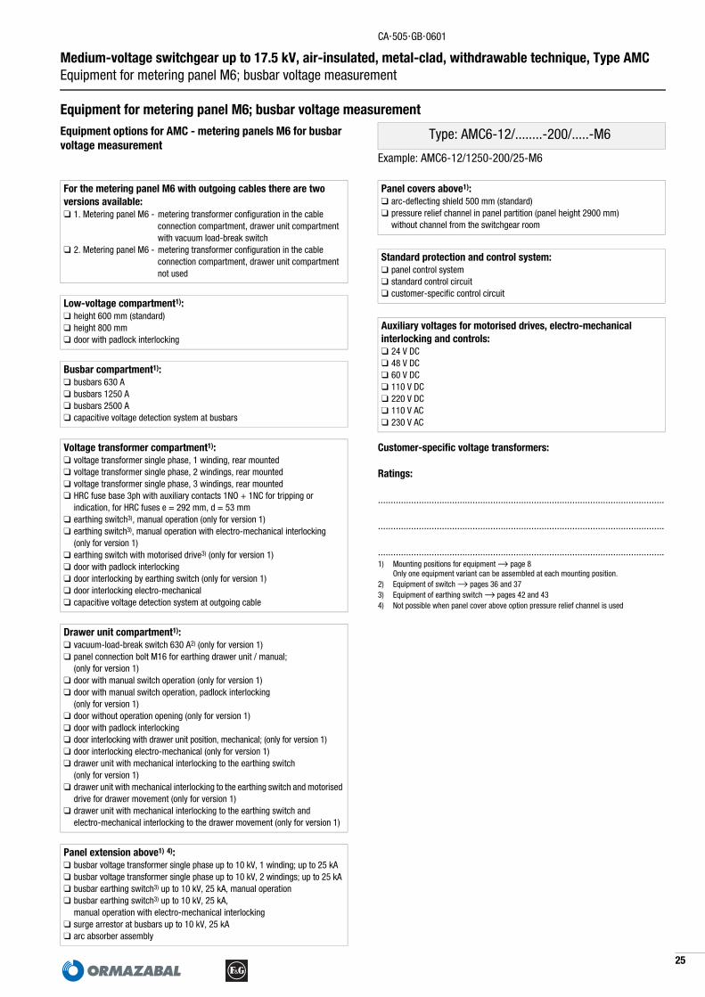
Equipment for metering panel M6; busbar voltage measurementEquipment options for AMC - metering panels M6 for busbar voltage measurement
Type: AMC6-12/........-200/.....-M6
Example: AMC6-12/1250-200/25-M6
For the metering panel M6 with outgoing cables there are twoversions available:❑ 1. Metering panel M6 - metering transformer configuration in the cable
connection compartment, drawer unit compartment with vacuum load-break switch
❑ 2. Metering panel M6 - metering transformer configuration in the cable connection compartment, drawer unit compartment not used
Low-voltage compartment1):❑ height 600 mm (standard)❑ height 800 mm❑ door with padlock interlocking
Busbar compartment1):❑ busbars 630 A❑ busbars 1250 A❑ busbars 2500 A❑ capacitive voltage detection system at busbars
Voltage transformer compartment1):❑ voltage transformer single phase, 1 winding, rear mounted❑ voltage transformer single phase, 2 windings, rear mounted❑ voltage transformer single phase, 3 windings, rear mounted❑ HRC fuse base 3ph with auxiliary contacts 1NO + 1NC for tripping or
indication, for HRC fuses e = 292 mm, d = 53 mm❑ earthing switch3), manual operation (only for version 1)❑ earthing switch3), manual operation with electro-mechanical interlocking
(only for version 1)❑ earthing switch with motorised drive3) (only for version 1)❑ door with padlock interlocking❑ door interlocking by earthing switch (only for version 1)❑ door interlocking electro-mechanical❑ capacitive voltage detection system at outgoing cable
Drawer unit compartment1):❑ vacuum-load-break switch 630 A2) (only for version 1)❑ panel connection bolt M16 for earthing drawer unit / manual;
(only for version 1)❑ door with manual switch operation (only for version 1)❑ door with manual switch operation, padlock interlocking
(only for version 1)❑ door without operation opening (only for version 1)❑ door with padlock interlocking❑ door interlocking with drawer unit position, mechanical; (only for version 1)❑ door interlocking electro-mechanical (only for version 1)❑ drawer unit with mechanical interlocking to the earthing switch
(only for version 1)❑ drawer unit with mechanical interlocking to the earthing switch and motorised
drive for drawer movement (only for version 1)❑ drawer unit with mechanical interlocking to the earthing switch and
electro-mechanical interlocking to the drawer movement (only for version 1)
Panel extension above1) 4):❑ busbar voltage transformer single phase up to 10 kV, 1 winding; up to 25 kA❑ busbar voltage transformer single phase up to 10 kV, 2 windings; up to 25 kA❑ busbar earthing switch3) up to 10 kV, 25 kA, manual operation❑ busbar earthing switch3) up to 10 kV, 25 kA,
manual operation with electro-mechanical interlocking❑ surge arrestor at busbars up to 10 kV, 25 kA❑ arc absorber assembly
Panel covers above1): ❑ arc-deflecting shield 500 mm (standard)❑ pressure relief channel in panel partition (panel height 2900 mm)
without channel from the switchgear room
Standard protection and control system:❑ panel control system ❑ standard control circuit❑ customer-specific control circuit
Auxiliary voltages for motorised drives, electro-mechanical interlocking and controls:❑ 24 V DC❑ 48 V DC❑ 60 V DC❑ 110 V DC❑ 220 V DC❑ 110 V AC❑ 230 V AC

CA⋅505⋅GB⋅0601
26
Medium-voltage switchgear up to 17.5 kV, air-insulated, metal-clad, withdrawable technique, Type AMCDelivery programme bus sectionaliser riser panel
Delivery programme bus sectionaliser riser panel
For section busbar riser panels HG there are two versions available:1. Bus sectionaliser riser panel HG - drawer unit compartment not used2. Bus sectionaliser riser panel HG - drawer unit compartment with disconnecting link
Technical data and dimensions2):
Configuration example for panel type ...-HG Other equipment options → page 27.
Rated voltage Ur [kV]
7.2 12 17.5
Rated current Ir for main busbars and section busbars
A 630 630 630
A 1250 1250 1250
A 2500 2500 2000
Panel height
Standard incl. arc-deflecting shield
mm 2700 2700 2700
with pressure relief channel mm 2900 2900 2900
Panel depth
mm 1400 1400 1400
Panel width for Ir
ï 1250 A mm 650/900
650/900
650/900
> 1250 A up to 2500 A mm 900 900 900
2) Additional technical data → pages 9 and 11.
������� � �������
Panel types1) Rated voltage Ur [kV]
7.2 12 17.5AMC6-12/630-630/20-HG • •AMC6-12/630-630/25-HG • •AMC6-12/630-630/31-HG • •AMC6-12/1250-1250/20-HG • •AMC6-12/1250-1250/25-HG • •AMC6-12/1250-1250/31-HG • •AMC9-12/630-630/20-HG • •AMC9-12/630-630/25-HG • •AMC9-12/630-630/31-HG • •AMC9-12/1250-1250/20-HG • •AMC9-12/1250-1250/25-HG • •AMC9-12/1250-1250/31-HG • •AMC9-12/2500-2500/20-HG • •AMC9-12/2500-2500/25-HG • •AMC9-12/2500-2500/31-HG • •AMC6-17/630-630/20-HG •AMC6-17/630-630/25-HG •AMC6-17/630-630/31-HG •AMC6-17/1250-1250/20-HG •AMC6-17/1250-1250/25-HG •AMC6-17/1250-1250/31-HG •AMC9-17/630-630/20-HG •AMC9-17/630-630/25-HG •AMC9-17/630-630/31-HG •AMC9-17/1250-1250/20-HG •AMC9-17/1250-1250/25-HG •AMC9-17/1250-1250/31-HG •AMC9-17/2000-2000/20-HG •AMC9-17/2000-2000/25-HG •AMC9-17/2000-2000/31-HG •1) Key to type references → page 9.

CA⋅505⋅GB⋅0601
7
Medium-voltage switchgear up to 17.5 kV, air-insulated, metal-clad, withdrawable technique, Type AMC Equipment for bus sectionaliser riser panel
2
1) Mounting positions for equipment → page 8 Only one equipment variant can be assembled at each mounting position.
2) Equipment of these devices → pages 38 and 393) Equipment of earthing switch → pages 42 and 434) Not possible when panel cover above option pressure relief channel is used
Equipment for bus sectionaliser riser panelEquipment options for AMC - section busbar riser panels HG Type: AMC...-...../........-......../.....-HG
Example: AMC6-12/1250-1250/25-HG
For section busbar riser panels HG there are two versions available:❑ 1. Bus sectionaliser riser panel HG - drawer unit compartment not used❑ 2. Bus sectionaliser riser panel HG - drawer unit compartment
with disconnecting link
Low-voltage compartment1):❑ height 600 mm (standard)❑ height 800 mm❑ door with padlock interlocking
Busbar compartment1):❑ busbars / section busbars 630 A❑ busbars / section busbars 1250 A❑ busbars / section busbars 2500 A❑ capacitive voltage detection system at busbars
Bus sectionaliser compartment1):❑ surge arrestor up to 10 kV at section busbar, front mounted❑ ball terminal bolt 25 mm, L1-L3 and panel fixing point for earthing❑ door with padlock interlocking❑ capacitive voltage detection system at section busbars
Panel extension above1) 4):❑ busbar voltage transformer single phase up to 10 kV,
1 winding; up to 25 kA (only at panel width 650 mm)❑ busbar voltage transformer single phase up to 10 kV,
2 windings; up to 25 kA (only at panel width 650 mm)❑ busbar earthing switch3) up to 10 kV, 25 kA, manual operation;
(only at panel width 650 mm)❑ busbar earthing switch3) up to 10 kV, 25 kA, manual operation with
electro-mechanical interlocking; (only at panel width 650 mm)❑ surge arrestor at busbars up to 10 kV, 25 kA (only at panel width 650 mm)❑ arc absorber assembly (standard equipment for AMC9)
Drawer unit compartment1):❑ disconnecting link2) 630 A, with electro-mechanical interlocking to drawer
movement; (only for version 2)❑ disconnecting link2) 1250 A, with electro-mechanical interlocking to drawer
movement; (only for version 2)❑ disconnecting link2) 2500 A, with electro-mechanical interlocking to drawer
movement; (only for version 2)❑ panel connection bolt M16 for earthing drawer unit / manual;
(only for version 2)❑ door without operation opening (only for version 2)❑ door with padlock interlocking❑ door interlocking with disconnecting link position, mechanical; (only for version 2)❑ door interlocking electro-mechanical
Panel covers above1): ❑ arc-deflecting shield 500 mm (standard)❑ pressure relief channel in panel partition (panel height 2900 mm)
without channel from the switchgear room
Auxiliary voltages for electro-mechanical interlocking and control (only for version 2):❑ 24 V DC❑ 48 V DC❑ 60 V DC❑ 110 V DC❑ 220 V DC❑ 110 V AC❑ 230 V AC
Control systems:❑ standard control circuit❑ customer-specific control circuit

CA⋅505⋅GB⋅0601
28
Medium-voltage switchgear up to 17.5 kV, air-insulated, metal-clad, withdrawable technique, Type AMCDelivery programme busbar riser panel; with cable connection
Delivery programme busbar riser panel; with cable connection
For busbar riser panels with cable connections there are two versions available:1. Busbar riser panel H - drawer unit compartment not used2. Busbar riser panel H - drawer unit compartment with disconnecting link
Technical data and dimensions2):
Configuration example for panel type ...-H Other equipment options → page 29.
Rated voltage Ur [kV]
7.2 12 17.5
Rated normal current Ir
for outgoing busbarsA 630 630 630
A 1250 1250 1250
A 2500 2500 2000
Panel height
Standard incl. arc-deflecting shield
mm 2700 2700 2700
with pressure relief channel mm 2900 2900 2900
Panel depth
mm 1400 1400 1400
Panel width for Ir
ï 1250 A mm 650/900
650/900
650/900
> 1250 A up to 2500 A mm 900 900 900
2) Additional technical data → pages 9 and 11.
������� � �������
Panel types1) Rated voltage Ur [kV]
7.2 12 17.5AMC6-12/630-630/20-H • •AMC6-12/1250-630/20-H • •AMC6-12/1250-1250/20-H • •AMC6-12/2500-630/20-H • •AMC6-12/2500-1250/20-H • •AMC6-12/630-630/25-H • •AMC6-12/1250-630/25-H • •AMC6-12/1250-1250/25-H • •AMC6-12/2500-630/25-H • •AMC6-12/2500-1250/25-H • •AMC6-12/630-630/31-H • •AMC6-12/1250-630/31-H • •AMC6-12/1250-1250/31-H • •AMC6-12/2500-630/31-H • •AMC6-12/2500-1250/31-H • •AMC9-12/630-630/20-H • •AMC9-12/1250-630/20-H • •AMC9-12/1250-1250/20-H • •AMC9-12/2500-630/20-H • •AMC9-12/2500-1250/20-H • •AMC9-12/2500-2500/20-H • •AMC9-12/630-630/25-H • •AMC9-12/1250-630/25-H • •AMC9-12/1250-1250/25-H • •AMC9-12/2500-630/25-H • •AMC9-12/2500-1250/25-H • •AMC9-12/2500-2500/25-H • •AMC9-12/630-630/31-H • •AMC9-12/1250-630/31-H • •AMC9-12/1250-1250/31-H • •AMC9-12/2500-630/31-H • •AMC9-12/2500-1250/31-H • •AMC9-12/2500-2500/31-H • •AMC6-17/630-630/20-H •AMC6-17/1250-630/20-H •AMC6-17/1250-1250/20-H •AMC6-17/2000-630/20-H •AMC6-17/2000-1250/20-H •AMC6-17/630-630/25-H •AMC6-17/1250-630/25-H •AMC6-17/1250-1250/25-H •AMC6-17/2000-630/25-H •AMC6-17/2000-1250/25-H •AMC6-17/630-630/31-H •AMC6-17/1250-630/31-H •AMC6-17/1250-1250/31-H •AMC6-17/2000-630/31-H •AMC6-17/2000-1250/31-H •AMC9-17/630-630/20-H •AMC9-17/1250-630/20-H •AMC9-17/1250-1250/20-H •AMC9-17/2000-630/20-H •AMC9-17/2000-1250/20-H •AMC9-17/2000-2000/20-H •AMC9-17/630-630/25-H •AMC9-17/1250-630/25-H •AMC9-17/1250-1250/25-H •AMC9-17/2000-630/25-H •AMC9-17/2000-1250/25-H •AMC9-17/2000-2000/25-H •AMC9-17/630-630/31-H •AMC9-17/1250-630/31-H •AMC9-17/1250-1250/31-H •AMC9-17/2000-630/31-H •AMC9-17/2000-1250/31-H •AMC9-17/2000-2000/31-H •1) Key to type references → page 9.

CA⋅505⋅GB⋅0601
9
Medium-voltage switchgear up to 17.5 kV, air-insulated, metal-clad, withdrawable technique, Type AMC Equipment for busbar riser panel; with cable connection
2
1) Mounting positions for equipment → page 8 Only one equipment variant can be assembled at each mounting position.
2) Equipment of these devices → pages 38 and 393) Equipment of earthing switch → pages 42 and 434) Not possible when panel cover above option pressure relief channel is used
Equipment for busbar riser panel; with cable connectionEquipment options for AMC - busbar riser panels H Type: AMC...-...../........-......../.....-H
Example: AMC9-12/2500-1250/25-H
For busbar riser panels with cable connections there are two versions available: ❑ 1. Busbar riser panel H - drawer unit compartment not used❑ 2. Busbar riser panel H - drawer unit compartment with disconnecting link
Low-voltage compartment1):❑ height 600 mm (standard)❑ height 800 mm❑ door with padlock interlocking
Busbar compartment1):❑ busbars / section busbars 630 A❑ busbars / section busbars 1250 A❑ busbars / section busbars 2500 A❑ capacitive voltage detection system at busbars
Cable connection compartment1):❑ outgoing busbars 630 A❑ outgoing busbars 1250 A❑ outgoing busbars 2500 A (only at panel width 900 mm)❑ surge arrestor up to 10 kV at outgoing, front mounted❑ cable connection 1 system per phase❑ cable connection 2 systems per phase❑ cable connection 3 systems per phase❑ cable connection 4 systems per phase (only at panel width 900 mm)❑ cable connection 5 systems per phase (only at panel width 900 mm)❑ cable connection 6 systems per phase (only at panel width 900 mm)❑ cable lug termination M12❑ cable lug termination M16❑ cable clamp size 1 (→ page 7)❑ cable clamp size 2 (→ page 7)❑ ball terminal bolt 25 mm, L1-L3 and panel fixing point for earthing❑ door with padlock interlocking❑ capacitive voltage detection system at outgoing cable
Panel extension above1) 4):❑ busbar voltage transformer single phase up to 10 kV,
1 winding; up to 25 kA (only at panel width 650 mm)❑ busbar voltage transformer single phase up to 10 kV,
2 windings; up to 25 kA (only at panel width 650 mm)❑ busbar earthing switch3) up to 10 kV, 25 kA, manual operation;
(only at panel width 650 mm)❑ busbar earthing switch3) up to 10 kV, 25 kA, manual operation with electro-
mechanical interlocking; (only at panel width 650 mm)❑ surge arrestor at busbars up to 10 kV, 25 kA
(only at panel width 650 mm)❑ arc absorber assembly (standard equipment for AMC9)
Drawer unit compartment1):❑ disconnecting link2) 630 A, with electro-mechanical interlocking to drawer
movement; (only for version 2)❑ disconnecting link2) 1250 A, with electro-mechanical interlocking to drawer
movement; (only for version 2)❑ disconnecting link2) 2500 A, with electro-mechanical interlocking to drawer
movement; (only for version 2)❑ panel connection bolt M16 for earthing drawer unit / manual;
(only for version 2)❑ door without operation opening (only for version 2)❑ door with padlock interlocking❑ door interlocking with disconnecting link position, mechanical; (only for version 2)❑ door interlocking electro-mechanical
Panel covers above1): ❑ arc-deflecting shield 500 mm (standard)❑ pressure relief channel in panel partition (panel height 2900 mm)
without channel from the switchgear room
Auxiliary voltages for electro-mechanical interlocking and controls (only for version 2):❑ 24 V DC❑ 48 V DC❑ 60 V DC❑ 110 V DC❑ 220 V DC❑ 110 V AC❑ 230 V AC
Control systems:❑ standard control circuit❑ customer-specific control circuit

CA⋅505⋅GB⋅0601
30
Medium-voltage switchgear up to 17.5 kV, air-insulated, metal-clad, withdrawable technique, Type AMCDelivery programme busbars earthing panel
Delivery programme busbars earthing panel
Technical data and dimensions2):
The busbar earthing panel offers additional configuration options for a busbar voltage measurement and for the connection of surge arrestors. As switch a vacuum circuit-breaker is used.
Configuration example for panel type ...-EOther equipment options → page 31.
Rated voltage Ur [kV]
7.2 12
Rated normal current Ir A 200 200
Panel height
Standard incl. arc-deflecting shield
mm 2700 2700
with pressure relief channel mm 2900 2900
Panel depth
mm 1400 1400
Panel width
mm 650 650
2) Additional technical data → pages 9 and 11.
�
�
Panel types1) Rated voltage Ur [kV]
7.2 12AMC6-12/630-200/20-E • •AMC6-12/1250-200/20-E • •AMC6-12/2500-200/20-E • •AMC6-12/630-200/25-E • •AMC6-12/1250-200/25-E • •AMC6-12/2500-200/25-E • •AMC6-12/630-200/31-E • •AMC6-12/1250-200/31-E • •AMC6-12/2500-200/31-E • •1) Key to type references → page 9.

CA⋅505⋅GB⋅0601
1
Medium-voltage switchgear up to 17.5 kV, air-insulated, metal-clad, withdrawable technique, Type AMC Equipment for busbar earthing panel
3
Customer-specific voltage transformers:
Ratings:
................................................................................................................
................................................................................................................
................................................................................................................1) Mounting positions for equipment → page 8
Only one equipment variant can be assembled at each mounting position.2) Equipment of switch→ pages 34 and 353) Not possible when panel cover above option pressure relief channel is used
Equipment for busbar earthing panelEquipment options for AMC - busbar earthing panels Type: AMC6-12/........-200/.....-E
Example: AMC6-12/2500-200/31-E
Low-voltage compartment1):❑ height 600 mm (standard)❑ height 800 mm❑ door with padlock interlocking
Busbar compartment1):❑ busbars 630 A❑ busbars 1250 A❑ busbars 2500 A❑ capacitive voltage detection system at busbars
Voltage transformer compartment1):❑ voltage transformer single phase, 1 winding, rear mounted❑ voltage transformer single phase, 2 windings, rear mounted❑ voltage transformer single phase, 3 windings, rear mounted❑ voltage transformer single phase, 1 winding, front mounted❑ voltage transformer single phase, 2 windings, front mounted❑ voltage transformer single phase, 1 winding,
with primary fuse up to 10 kV, front mounted❑ voltage transformer single phase, 2 windings,
with primary fuse up to 10 kV, front mounted❑ surge arrestor up to 10 kV, at main busbar❑ door with padlock interlocking❑ electro-mechanical door interlocking ❑ capacitive voltage detection system at busbars
Panel extension above1) 3):❑ arc absorber assembly
Drawer unit compartment1):❑ vacuum circuit-breaker 630 A2)
❑ panel connection bolt M16 for earthing drawer unit / manual❑ door with manual switch operation❑ door with manual switch operation, padlock interlocking❑ door without operation opening❑ door with padlock interlocking❑ door interlocking with drawer unit position, mechanical❑ door interlocking electro-mechanical.❑ electro-mechanical interlocking to the drawer movement❑ drawer unit with motorised drive for drawer movement
Panel covers above1): ❑ arc-deflecting shield 500 mm (standard)❑ pressure relief channel in panel partition (panel height 2900 mm)
without channel from the switchgear room
Standard protection and control system:❑ panel control system ❑ standard control circuit❑ customer-specific control circuit
Auxiliary voltages for motorised drives, electro-mechanical interlocking and controls:❑ 24 V DC❑ 48 V DC❑ 60 V DC❑ 110 V DC❑ 220 V DC❑ 110 V AC❑ 230 V AC

CA⋅505⋅GB⋅0601
32
Medium-voltage switchgear up to 17.5 kV, air-insulated, metal-clad, withdrawable technique, Type AMCDelivery programme contactor panel
Delivery programme contactor panel
Technical data and dimensions2):
The rated short-time withstand current Ik at the outgoing busbars is limited by the HRC fuses.The three-phase tripping of the vacuum contactor is performed elec-trically by the auxiliary contacts of the fuse base and/or the vacuum contactor trip element.
At HRC fuse base high-voltage fuses 3/7.2 kV according to DIN 43625 and IEC 60282-1, dimension e = 292 mm, d = up to 85 mm can be implemented.For HRC fuse application recommendation see fuse selection table for AMC6-7/...-200/...-S panel. AMC contactor panels are often used for switching medium-voltage motors. For additional protection of motor ï 55 kW surge arrestors are assembled.
As standard the vacuum contactors are equipped with latched operating circuit.
Configuration example for panel type ...-SOther equipment options → page 33.
Rated voltage Ur [kV]
7.2
Rated normal current Ir
for outgoing busbars (continuous current)
A 200
Panel height
Standard incl. arc-deflecting shield
mm 2700
with pressure relief channel mm 2900
Panel depth
mm 1400
Panel width
mm 650
2) Additional technical data → pages 9 and 11.
�
���
��
Panel types1) Rated voltage Ur [kV]
7.2AMC6-7/630-200/20-S •AMC6-7/1250-200/20-S •AMC6-7/2500-200/20-S •AMC6-7/630-200/25-S •AMC6-7/1250-200/25-S •AMC6-7/2500-200/25-S •AMC6-7/630-200/31-S •AMC6-7/1250-200/31-S •AMC6-7/2500-200/31-S •1) Key to type references → page 9.

CA⋅505⋅GB⋅0601
3
Medium-voltage switchgear up to 17.5 kV, air-insulated, metal-clad, withdrawable technique, Type AMC Equipment for contactor panel
3
Customer-specific current and voltage transformers:
Ratings:
................................................................................................................
................................................................................................................
................................................................................................................1) Mounting positions for equipment → page 8
Only one equipment variant can be assembled at each mounting position.2) Equipment of contactor → pages 40 and 413) Only one cable connection per phase possible4) Necessary for applications with MV motors õ1000 kW5) Equipment of earthing switch → pages 42 and 436) Not possible when panel cover above option pressure relief channel is used
Equipment for contactor panelEquipment options for AMC - contactor panels Type: AMC6-7/........-200/.....-S
Example: AMC6-7/1250-200/25-S
Low-voltage compartment1):❑ height 600 mm (standard)❑ height 800 mm❑ door with padlock interlocking
Busbar compartment1):❑ busbars 630 A❑ busbars 1250 A❑ busbars 2500 A❑ capacitive voltage detection system at busbars
Cable connection compartment1):❑ outgoing busbars 200 A; continuous current rating❑ support current transformer 1 core❑ support current transformer 2 cores❑ support current transformer 3 cores❑ voltage transformer single phase, 1 winding, rear mounted❑ voltage transformer single phase, 2 windings, rear mounted❑ voltage transformer single phase, 3 windings, rear mounted❑ voltage measurement before current measurement, rear mounted❑ voltage measurement after current measurement, rear mounted❑ fixed compensation 3ph up to 133 kVAR, 7.2 kV3)
❑ earthing switch5), manual operation❑ earthing switch5), manual operation with electro-mechanical interlocking❑ earthing switch with motorised drive5)
❑ voltage transformer single phase, 1 winding, front mounted❑ voltage transformer single phase, 2 windings, front mounted❑ voltage transformer single phase, 1 winding,
with primary fuse up to 6.6 kV, front mounted❑ voltage transformer single phase, 2 windings,
with primary fuse up to 6.6 kV, front mounted❑ outgoing cable surge arrestor up to 6.6 kV, front mounted❑ cable connection 1 system per phase❑ cable connection 2 systems per phase❑ cable connection 3 systems per phase❑ cable lug termination M12❑ cable lug termination M16❑ cable clamp size 1 (→ page 7)❑ cable clamp size 2 (→ page 7)❑ ball terminal bolt 25 mm, L1-L3 and panel fixing point for earthing❑ door with padlock interlocking❑ door interlocking by earthing switch❑ door interlocking electro-mechanical.❑ capacitive voltage detection system at outgoing cable
Panel extension above1) 6):❑ busbar voltage transformers single phase up to 6.6 kV,
1 winding; up to 25 kA❑ busbar voltage transformers single phase up to 6.6 kV,
2 windings; up to 25 kA❑ busbar earthing switch5) up to 6.6 kV, 25 kA, manual operation❑ busbar earthing switch5) up to 6.6 kV, 25 kA,
manual operation with electro-mechanical interlocking❑ surge arrestor at busbars up to 6.6 kV, 25 kA❑ arc absorber assembly
Drawer unit compartment1):❑ vacuum contactor incl. HRC fuse base2)
❑ fan unit for forced-air ventilation4)
❑ panel connection bolt M16 for earthing drawer unit / manual❑ door with manual contactor operation OFF❑ door with manual contactor operation OFF, padlock interlocking❑ door without operation opening❑ door with padlock interlocking❑ door interlocking with drawer unit position, mechanical❑ door interlocking electro-mechanical.❑ drawer unit with mechanical interlocking to the earthing switch❑ drawer unit with mechanical interlocking to the earthing switch and
electro-mechanical interlocking to the drawer movement
Panel covers above1): ❑ arc-deflecting shield 500 mm (standard)❑ pressure relief channel in panel partition (panel height 2900 mm)
without channel from the switchgear room
Standard protection and control system:❑ panel control system with integral time overcurrent protection ❑ standard control circuit with time overcurrent protection❑ standard control circuit with basic motor protection❑ customer-specific protection and control systems
Auxiliary voltages for motorised drive electro-mechanical interlocking and controls:❑ 24 V DC❑ 48 V DC❑ 60 V DC❑ 110 V DC❑ 220 V DC❑ 110 V AC❑ 230 V AC
Auxiliary voltages for fan unit:❑ 110 V AC❑ 230 V AC

CA⋅505⋅GB⋅0601
34
Medium-voltage switchgear up to 17.5 kV, air-insulated, metal-clad, withdrawable technique, Type AMCDelivery programme vacuum circuit-breaker drawer unit
Drawer unit ranges/equipmentDelivery programme vacuum circuit-breaker drawer unit
Technical data2): optional
Rated voltage Ur [kV]
7.2 12 17.5
Rated normal current Ir A 630 630 630
A 1250 1250 1250
A 2500 2500 2000
Rated-short circuit-breaking current Isc and short-time current Ik, at tk = 3 s
kA 20 20 20
kA 25 25 25
kA 31.5 31.5 31.5
Rated peak withstand current Ip
kA 50 50 50
kA 62.5 62.5 62.5
kA 80 80 80
Rated switching sequence O - 0.3 - CO 15 s - CO
Class E1, C2, M2
Mechanical switching operations 10000 x
2) Additional technical data → page 11.
Circuit-breaker types1) Instal-lation
Rated voltage Ur [kV]
7.2 12 17.5NVL2F-12/20/630-150C AMC6 • •NVL2F-12/25/630-150C AMC6 • •NVL2F-12/31/630-150C AMC6 • •NVL2F-12/20/1250-150C AMC6 • •NVL2F-12/25/1250-150C AMC6 • •NVL2F-12/31/1250-150C AMC6 • •NVL2F-12/20/630-210C AMC9 • •NVL2F-12/25/630-210C AMC9 • •NVL2F-12/31/630-210C AMC9 • •NVL2F-12/20/1250-210C AMC9 • •NVL2F-12/25/1250-210C AMC9 • •NVL2F-12/31/1250-210C AMC9 • •NVL3F-12/20/2500-210C AMC9 • •NVL3F-12/25/2500-210C AMC9 • •NVL3F-12/31/2500-210C AMC9 • •NVL2F-17/20/630-150C AMC6 •NVL2F-17/25/630-150C AMC6 •NVL2F-17/31/630-150C AMC6 •NVL2F-17/20/1250-150C AMC6 •NVL2F-17/25/1250-150C AMC6 •NVL2F-17/31/1250-150C AMC6 •NVL2F-17/20/630-210C AMC9 •NVL2F-17/25/630-210C AMC9 •NVL2F-17/31/630-210C AMC9 •NVL2F-17/20/1250-210C AMC9 •NVL2F-17/25/1250-210C AMC9 •NVL2F-17/31/1250-210C AMC9 •NVL3F-17/20/2000-210C AMC9 •NVL3F-17/25/2000-210C AMC9 •NVL3F-17/31/2000-210C AMC9 •1) Key to type references → page 9.

CA⋅505⋅GB⋅0601
5
Medium-voltage switchgear up to 17.5 kV, air-insulated, metal-clad, withdrawable technique, Type AMC Equipment for vacuum circuit-breaker drawer unit
3
1) Further accessories on request
Equipment for vacuum circuit-breaker drawer unitEquipment options for AMC vacuum circuit-breaker drawer units Type: NVL...F-…./…./……-.....C
Example: NVL2F-12/25/1250-150C
Standard equipment of circuit-breakers:■ charged spring drive with manual actuation■ 1. trip element “OFF”■ 64-pin plug connector with mechanical interlocking■ auxiliary contacts 5 NO + 5 NC (4 NO + 5 NC free available)■ fleeting contact switch message “OFF”■ mechanical counter■ contact arms■ mechanical push-buttons “ON” and “OFF”■ mechanical position indicator■ mechanical spring charge indicator
Additional equipment for circuit-breakers1):❑ motorised accumulator drive incl. trip element “ON”, annunciator switch for
spring charging, anti-pumping relay❑ 2. trip element “OFF”❑ 3. trip element “OFF” with auxiliary contacts, extension 5 NO + 5 NC❑ transformer operated trip, alternative to 1. or 2. trip element❑ undervoltage release, 100 V AC (non-delayed) alternative to 2. trip element❑ auxiliary contact extension 5 NO + 5 NC❑ message spring accumulator tensioned❑ electric closing lock-out
Standard equipment for drawer units:■ mechanical drawer movement, manual operation■ mechanical interlocking to the earthing switch■ mechanical button actuation for circuit-breaker push-button■ auxiliary contacts position “Disconnected position” 3 change-over contacts
(2 free available)■ auxiliary contacts position “Connected position” 3 change-over contacts
(2 free available)
Additional equipment for drawer unit1):❑ motorised drive for drawer movement❑ electro-mechanical interlocking for drawer movement
Auxiliary voltages for circuit-breaker 24 V DC 48 V DC 60 V DC 110 V DC 220 V DC 110 V AC 230 V AC
Motorised drive, spring force charging
1. trip element “Off”
2. trip element “Off”
3. trip element “Off”
trip element “On”
electric closing lock-out
Auxiliary voltages for drawer unit 24 V DC 48 V DC 60 V DC 110 V DC 220 V DC 110 V AC 230 V AC
motorised drive
electro-mechanical interlocking

CA⋅505⋅GB⋅0601
36
Medium-voltage switchgear up to 17.5 kV, air-insulated, metal-clad, withdrawable technique, Type AMCDelivery programme vacuum load-break switch drawer unit
Delivery programme vacuum load-break switch drawer unit
Technical data2):
Rated voltage Ur [kV]
7.2 12 17.5
Rated normal current Ir A 630 630 630
Rated short-time current Ik, at tk = 3 s
kA 20 20 20
kA 25 25 25
Rated short-circuit making current Ima
kA 50 50 50
kA 62.5 62.5 62.5
Rated distribution line closed-loop breaking current I2a
A 630 630 630
Rated no-load transformer breaking current I3
A 6.3 6.3 6.3
Rated cable-charging breaking current I4a
A 31.5 31.5 31.5
Rated earth-fault breaking current I6a
A 630 630 630
Rated cable-charging breaking current under earth-fault conditions I6b
A 31.5 31.5 31.5
Switching operations at Ima Mechanical switching operations
5 x5000 x
2) Additional technical data → page 11.
Load-break switch types1)
Installation in
Rated voltage Ur [kV]
7.2 12 17.5NVLT2F-12/20/630-150C AMC6 • •NVLT2F-12/25/630-150C AMC6 • •NVLT2F-17/20/630-150C AMC6 •NVLT2F-17/25/630-150C AMC6 •1) Key to type references → page 9.

CA⋅505⋅GB⋅0601
7
Medium-voltage switchgear up to 17.5 kV, air-insulated, metal-clad, withdrawable technique, Type AMC Equipment for vacuum load-break switch drawer unit
3
1) Further accessories on request
Equipment for vacuum load-break switch drawer unitEquipment options for AMC vacuum load-break switchdrawer units Type: NVLT2F- 630-150C
Example: NVLT2F-12/20/630-150C
Standard equipment for load-break switch:■ charged spring drive “OFF” with manual actuation■ spring drive “ON” with manual actuation■ trip element “OFF”■ 64-pin plug connector with mechanical interlocking■ auxiliary contacts 5 NO + 5 NC (4 NO + 5 NC free available)■ fleeting contact witch annunciation “OFF”■ mechanical counter■ contact arms■ mechanical push- button “OFF”■ mechanical position indicator■ mechanical spring charge indicator
Additional equipment for load-break switch1):❑ spring drive “ON” with motorised actuation❑ undervoltage release, 100 V AC (non-delayed)❑ auxiliary contact extension 5 NO + 5 NC❑ electric closing lock-out
Standard equipment for drawer units:■ mechanical drawer movement, manual operation■ mechanical interlocking to the earthing switch■ mechanical push-button actuation for load-break switch push-button■ auxiliary contacts position “Disconnected position” 3 change-over contacts
(2 free available)■ auxiliary contacts position “Connected position” 3 change-over contacts
(2 free available)
Additional equipment for drawer unit1):❑ motorised drive for drawer movement❑ electro-mechanical interlocking for drawer movement
Auxiliary voltage for load-break switch 24 V DC 48 V DC 60 V DC 110 V DC 220 V DC 110 V AC 230 V AC
motorised drive, spring mechanism “ON”
trip element “Off”
electric closing lock-out
Auxiliary voltages for drawer unit 24 V DC 48 V DC 60 V DC 110 V DC 220 V DC 110 V AC 230 V AC
motorised drive
electro-mechanical interlocking

CA⋅505⋅GB⋅0601
38
Medium-voltage switchgear up to 17.5 kV, air-insulated, metal-clad, withdrawable technique, Type AMCDelivery programme disconnecting link drawer unit
Delivery programme disconnecting link drawer unit
Technical data2): optional
Rated voltage Ur [kV]
7.2 12 17.5
Rated normal current Ir A 630 630 630
A 1250 1250 1250
A 2500 2500 2000
Ratedshort-time current Ik, at tk = 3 s
kA 20 20 20
kA 25 25 25
kA 31.5 31.5 31.5
Rated peak withstand current Ip
kA 50 50 50
kA 62.5 62.5 62.5
kA 80 80 80
2) Additional technical data → page 11.
Disconnecting link types1)
Installation in
Rated voltage Ur [kV]
7.2 12 17.5NTB2F-12/20/630-150C AMC6 • •NTB2F-12/25/630-150C AMC6 • •NTB2F-12/31/630-150C AMC6 • •NTB2F-12/20/1250-150C AMC6 • •NTB2F-12/25/1250-150C AMC6 • •NTB2F-12/31/1250-150C AMC6 • •NTB2F-12/20/630-210C AMC9 • •NTB2F-12/25/630-210C AMC9 • •NTB2F-12/31/630-210C AMC9 • •NTB2F-12/20/1250-210C AMC9 • •NTB2F-12/25/1250-210C AMC9 • •NTB2F-12/31/1250-210C AMC9 • •NTB3F-12/20/2500-210C AMC9 • •NTB3F-12/25/2500-210C AMC9 • •NTB3F-12/31/2500-210C AMC9 • •NTB2F-17/20/630-150C AMC6 •NTB2F-17/25/630-150C AMC6 •NTB2F-17/31/630-150C AMC6 •NTB2F-17/20/1250-150C AMC6 •NTB2F-17/25/1250-150C AMC6 •NTB2F-17/31/1250-150C AMC6 •NTB2F-17/20/630-210C AMC9 •NTB2F-17/25/630-210C AMC9 •NTB2F-17/31/630-210C AMC9 •NTB2F-17/20/1250-210C AMC9 •NTB2F-17/25/1250-210C AMC9 •NTB2F-17/31/1250-210C AMC9 •NTB3F-17/20/2000-210C AMC9 •NTB3F-17/25/2000-210C AMC9 •NTB3F-17/31/2000-210C AMC9 •1) Key to type references → page 9.

CA⋅505⋅GB⋅0601
9
Medium-voltage switchgear up to 17.5 kV, air-insulated, metal-clad, withdrawable technique, Type AMC Equipment for disconnecting link drawer unit
3
Equipment for disconnecting link drawer unitEquipment options for AMC - disconnecting link drawer units Type: NTB...F-…./…./……-.....C
Example: NTB2F-12/25/1250-150C
Standard equipment for disconnecting link:■ contact arms■ insulated busbar link
Standard equipment for drawer units:■ mechanical drawer movement, manual operation■ mechanical interlocking to the earthing switch■ electro-mechanical interlocking for the drawer movement■ auxiliary contacts position “Disconnected position” 3 change-over contacts■ auxiliary contacts position “Connected position” 3 change-over contacts
Auxiliary voltages for drawer unit 24 V DC 48 V DC 60 V DC 110 V DC 220 V DC 110 V AC 230 V AC
electro-mechanical interlocking

CA⋅505⋅GB⋅0601
40
Medium-voltage switchgear up to 17.5 kV, air-insulated, metal-clad, withdrawable technique, Type AMCDelivery programme vacuum contactor drawer unit
Delivery programme vacuum contactor drawer unit
Technical data2):
Rated voltage Ur [kV]
7.2
Rated normal current Ie
continuous currentA 200
Rated short-time current lk kA Value is limited by HRC fuses.
Rated duration of short circuit tk
s 1
Rated short-circuit breaking current Isc
kA 503)
Fuse dimension of HRC fuse “e”
mm 292
Rated maximum current for HRC fuse
A 355
Maximum switching operations per hour
300 X4)
Switching operations at Ie (category AC3)
250000 X4)
Mechanical switching operations 250000 X
2) Additional technical data → page 11.3) Rated breaking current of the HRC fuse must be considered4) Vacuum contactor with latched operating circuit
Contactor type1) Installation in
Rated voltage Ur [kV]
7.2NVSF-7/6/200-150C AMC6 •1) Key to type references → page 9.

CA⋅505⋅GB⋅0601
1
Medium-voltage switchgear up to 17.5 kV, air-insulated, metal-clad, withdrawable technique, Type AMC Equipment for vacuum contactor drawer unit
4
Equipment for vacuum contactor drawer unitEquipment options for AMC vacuum contactor drawer units Type: NVSF-7/6/200-150C
Standard equipment for contactors:■ latched operating circuit■ closing coil “ON”■ trip coil “OFF”■ plug connector for control cable■ auxiliary contacts 3 NO + 3 NC (2 NO + 2 NC free available)■ mechanical counter■ contact arms■ mechanical position indicator
Standard equipment for drawer units:■ mechanical drawer movement, manual operation■ mechanical interlocking to the earthing switch■ auxiliary contacts position “Disconnected position” 3 change-over contacts
(2 free available)■ auxiliary contacts position “Connected position” 3 change-over contacts
(2 free available)
Additional equipment drawer unit:❑ electro-mechanical interlocking for drawer movement
Auxiliary voltages for contactor 24 V DC 48 V DC 60 V DC 110 V DC 220 V DC 110 V AC 230 V AC
closing coil “ON”
trip coil “OFF”
Auxiliary voltages for drawer unit 24 V DC 48 V DC 60 V DC 110 V DC 220 V DC 110 V AC 230 V AC
electro-mechanical interlocking

CA⋅505⋅GB⋅0601
42
Medium-voltage switchgear up to 17.5 kV, air-insulated, metal-clad, withdrawable technique, Type AMCDelivery programme earthing switch
Delivery programme earthing switch
Earthing switch, type EDL
Assembled as outgoing earthing switch at panel types -L, -LG, -K and -S.
Assembled as busbar earthing switch up to Ik = 25 kA in the panel extension above.
Technical data2):
2) Additional technical data → page 11.
Earthing switch type DES
Assembled as outgoing earthing switch in panel types AMC6-12/...-200-...-T and -M6.
Technical data2):
Earthing switch types
Installationat
Rated voltage Ur [kV]
7.2 12 17.5EDL150/31 AMC6 • • •EDL210/31 AMC9 • • •
Rated voltage Ur [kV]
7.2 12 17.5
Ratedshort-time current Ik, at tk = 3 s
kA 31.5 31.5 31.5
Rated short-circuit making current Ima
kA 80 80 80
Switching operations at Ima Mechanical switching operations
5 x1000 x
Class E2
Earthing switch type
Installationat
Rated voltage Ur [kV]
7.2 12DES10/630-135 AMC6 • •
Earthing switch type Rated voltage Ur [kV]
7.2 12
Rated short-time current Ik, at tk = 1 s
kA 20 20
Rated short-circuit making current Ima
kA 50 50
Switching operations at Ima Mechanical switching opera-
2 x1000 x
Class E1

CA⋅505⋅GB⋅0601
3
Medium-voltage switchgear up to 17.5 kV, air-insulated, metal-clad, withdrawable technique, Type AMC Equipment for earthing switch
4
Equipment for earthing switchEquipment options for AMC earthing switch Type: EDL150/31
EDL210/31DES10/630-135
Standard equipment for earthing switches:■ spring drive mechanism “ON”■ manual operation with position indicator
Additional equipment for earthing switches:❑ motorised drive for actuation❑ auxiliary contact extension 2 NO + 2 NC❑ electro-mechanical interlocking
Auxiliary voltage for earthing switch 24 V DC 48 V DC 60 V DC 110 V DC 220 V DC 110 V AC 230 V AC
motorised drive
electro-mechanical interlocking

CA⋅505⋅GB⋅0601
44
Medium-voltage switchgear up to 17.5 kV, air-insulated, metal-clad, withdrawable technique, Type AMCInstallation in the switchgear room
Installation in the switchgear room
Operating premises and intended use
The AMC switchgear can be used for indoors installationsaccording to VDE 0101. At this junctureIEC 62271-200 (VDE 0671 part 200) and IEC 60694 (VDE 0670 part 1000) must be considered.
Equipment installation in the switchgear room
End cassette
Left end panel
Middle panel
Right end panel
Overall height of standard panel 2700 mm
Fastening bores 28 x 14
Floor contact area
Wiring duct
Dimensions in mm
Personnel safety
This AMC switchgear has been type-tested according to IEC 62271-200 (VDE 0671 part 200) arc-fault qualification IAC AFL.
The switchgear should be installed so that the greatest possible level of personnel safety is provided. In the standard version, pres-sure relief flaps on the top released in the event of an internal arc upwards.
To increase the personnel safety and to reduce the pressure in the switchgear room in the event of an internal arc, AMC switchgear can be equipped with arc absorber assemblies (standard equip-ment for Ik = 31.5 kA) instead of the pressure relief flaps.A further option with a pressure relief channel to exhaust the hot gases from the switchgear room is available. → page 6.
max. 75min. 40
min. 40
min.
40
min.
40
58
min.
100
62 58 A2
630
DA141 41
35
B
1397
304
1300
max. 75
203
193.
5
32 32
BBBB 30 30
min.
100
1397
G
T
min. 100min. 100
Panel width B D A1 A2
650 500 534 574
900 750 824 784
B
A
C
100 25
2200
500
1400

CA⋅505⋅GB⋅0601
5
Medium-voltage switchgear up to 17.5 kV, air-insulated, metal-clad, withdrawable technique, Type AMC Vacuum circuit-breaker
4
Vacuum circuit-breaker
Type NVL vacuum circuit-breaker
The vacuum circuit-breaker type NVL consists of the basic switch frame, the three switch poles and the switch mechanism. The switch poles and switch mechanism are mounted on the basic switch frame.
The vacuum circuit-breaker type NVL is an Ormazabal product and is suitable for switching:
• Cables and overhead power lines• Transformers• Motors• Generators
Vacuum circuit-breakers can also be used for the following switching functions:
• Synchronisation• Short-time interruption.
Switch poles
The switch poles include the vacuum switching chamber with contact system, the contact pressure spring, the tripping spring, as well as cast-resin parts.
The cast-resin parts are for insulation, support and protection. In addition to their insulating function, they also absorb external forces from the switching process, contacting and short-circuit forces. They also provide mechanical protection for the vacuum chamber.
Switch mechanism
The switch mechanism is designed as a spring accumulator drive. The closing spring is charged by means of manual cranking or by motor. The operation can be done by manual push-buttons or by electrical trip elements. During the making process, theclosing spring charges the contact pressure spring and closes the contacts. At the same time, the tripping springs are charged. To achieve operational capability short-time interruption, after the closing spring has been discharged it is recharged either manually or automatically if a motorised drive is mounted. By this means the necessary energy is stored for a short-time interruption, such as the switching sequence “OFF”-“ON”-“OFF”.
Vacuum circuit-breaker for rated voltages up to 17.5 kV
Switch pole with cast resin insulator and support

CA⋅505⋅GB⋅0601
46
Medium-voltage switchgear up to 17.5 kV, air-insulated, metal-clad, withdrawable technique, Type AMCCapacitive voltage detection system
Capacitive voltage detection system
Capacitive voltage detection system
For hazard-free detection of the operating voltage, the panels can optionally be equipped with capacitive voltage detection systems according to IEC 61243-5. There are two installation positions available for the capacitive insulators:
• at the main busbar• at the outgoing busbars (→ page 7)
The indication is funded by a continuous voltage detection system according to IEC 61243-5 with the necessary interfaces placed at the door of the low voltage compartment.
The visualisation is designed separately for each phase, for example by high-intensity LEDs.
A phase comparator can be connected for checking the phase sequence.
Version examples:
Type: CPI VI-3P (standard version)
- no auxiliary voltage required
Type: CPI VI-3P/R - with relay output 2 W (change-over contact)(max. AC 230 V, 3 A)
- auxiliary voltagesDC: 48 V, 60 V, 110 V, 220 V AC: 110 V, 230 V
Indication range according to IEC 61243-5
U0 < 10% UN = no voltage present
U0 > 45% UN = voltage present
Capacitive detection system in the door of the low voltage compartment
Busbar compartment with capacitive insulators

CA⋅505⋅GB⋅0601
7
Medium-voltage switchgear up to 17.5 kV, air-insulated, metal-clad, withdrawable technique, Type AMC Switchgear accessories
4
Switchgear accessories
Busbar earthing drawer unit
Optional busbar earthing drawer units in the drawer unit compartment of the panel can be used for earthing main busbar sections in installations. This requires only that the drawer unit compartment is equipped with a standard drawer unit and the option “panel connection bolt” → page 13.
Busbar earthing drawer unit type
Installation at
Rated voltage Ur [kV]
7.2 12 17.5NSE2F-17/31-150C AMC6 • • •NSE2F-17/31-210C1) AMC9 • • •NSE3F-17/31-210C2) AMC9 • • •1) For AMC9 panels with outgoing busbars up to 1250 A2) For AMC9 panels with outgoing busbars up to 2500 A
Auxiliary carriage
An auxiliary carriage serves the purpose of inserting and removing of the drawer units. It can be adjusted to match the height of the panel and compensate for unevenness at the floor. The inter-locking of the drawer unit to the auxiliary carriage, locking bolts to fix the carriage on the switchgear panel and move-in guides to the rails in the drawer unit compartment ensure user-friendly and safe operation.
Operating levers
The following levers are provided for operation:
Manual crank handle for the spring accumulator of the switch
Manual crank handle for moving the drawer units
Switching lever for manual actuation of the earthing switch
Fastener key for manual actuation of the switchgear drawer units in connected position and for interlocking the front doors
Emergency crank handle for motorised earthing switch (optional)

CA⋅505⋅GB⋅0601
48
Medium-voltage switchgear up to 17.5 kV, air-insulated, metal-clad, withdrawable technique, Type AMCConfiguration examples of protection and control systems
Configuration examples of protection and control systems
Combined protection and control systemsThe CSP/CMP combined protection and control systems are used for automating switchgear installations. It is built into the low voltage compartment (CSP2 base unit) and the compartment door (CMP1 display and operator panel).
Range of functions• Protective technology• Control technology (switching elements)• Measurement and evaluation (current and voltage)• Communication interfaces (PC and control system)• Display of the circuit diagram (including switch positions)• SL-SOFT configuration software
CSP2 base unit• Compact insulated housing design according to IP50• Integrated protection and control functions (depending on type
of device)• Communication interfaces• Fail-safe fault recording function• Programmable logic functions
Protection functionsThe protection functions are activated and configured via the CMP1 or SL-SOFT, depending on application and customer speci-fication. The availability of the protection functions depends on the type of device:
• Differential protection• Time-overcurrent protection (directional/non-directional)• Short-circuit protection (directional/non-directional)• Earth-fault protection (directional/non-directional)• Overload protection with thermal replica• Overvoltage/undervoltage protection• Overfrequency/underfrequency protection• Directional power protection• Negative sequence protection• Auto reclosing after tripping• Control circuit monitoring • Temperature monitoring (analogue)• etc.
System advantages• Higher degree of system automation• Reduction in material costs, engineering and documentation by
means of the integration of various functions within a single device
• Configurable system and protection parameters, plus messages and displays
• All CSP2/CMP1 systems can be connect into a higher-level control system
• Optimum remote monitoring of all switching, indication, measuring and protection functions
• Storage of event and fault messages for traceability (fail-safe)
CMP1 display and operator panel• Flat and compact construction• CAN, RS232 communication interfaces• LCD graphics display for indication of current switch positions
and measured values• Keypad at the front according to IP50• Locally allocation of parameters
MeteringA large number of metering functions are offered, depending on the type of device.These include:
• Differential currents• Phase currents and voltages• Active and reactive power• Active/reactive energy metering• Min./max.values for currents and voltages, frequency etc.• Fault values etc.
CommunicationVarious communication interfaces are available: CAN-Bus, RS232, RS85, fibre optic cable. Data protocol types: IEC 60870-5-103, Profibus DP or Modbus RTU.
CSP2 base unit CMP1 display and operator panel

CA⋅505⋅GB⋅0601
49
Notes

CA⋅505⋅GB⋅0601
50
Notes


SF6-insulated switchgear
type GAtype GAEtype CPG.0
Air-insulated switchgear
type EAtype AMC
Air-insulated switches
type NVLtype KL(F), T, DES
Subject to alteration CA 505 GB 0601
Ormazabal Anlagentechnik GmbHAm Neuerhof 31D-47804 KrefeldTel.: +49 (0) 2151 7151 – 0Fax: +49 (0) 2151 7151 – 38 or 75e-mail: [email protected]