Medium Voltage Embedded Generation Technical Requirements
56
Medium Voltage Embedded Generation Technical Requirements Record Number: R0002006753 Version Number: 1.0 Date: September 2021
Transcript of Medium Voltage Embedded Generation Technical Requirements
Medium Voltage Embedded Generation Technical Requirements
Record Number: R0002006753
Version Number: 1.0
Date: September 2021
2
Medium Voltage Embedded Generation Technical Requirements
Contents
Disclaimer 5
1 Introduction 6
1.1 Scope 7
1.2 Proponent responsibilities 7
1.3 TasNetworks’ responsibilities 8
1.4 Responsibilities of Designers, Consultants and Installers 8
2 Definitions and abbreviations 9
2.1 Definitions 9
2.2 Abbreviations 11
2.3 Terminology 11
2.4 Subcategories 12
3 Relevant rules, regulations, standards and codes 13
3.1 TasNetworks’ standards 13
3.2 Standards and codes 13
3.3 Legislation and regulation 14
3.4 Operating limits 15
3.4.1 Standard Operating Voltages 15
3.4.2 Standard power system frequency 16
4 Classification of generation 17
4.1 Access standards for generators exempt from registration 17
4.2 Generation technologies 18
4.2.1 Synchronous machines 18
4.2.2 Asynchronous (induction) machines 19
4.2.3 Inverter energy systems 19
5 Technical requirements 20
5.1 Generator performance access standards 20
5.1.1 Reactive power capability and power factor requirements (S5.2.5.1) 21
5.1.2 Quality of electricity generated (S5.2.5.2) 22

3
Medium Voltage Embedded Generation Technical Requirements
5.1.3 Generating unit response to frequency disturbances (S5.2.5.3) 24
5.1.4 Generating unit response to voltage disturbances (S5.2.5.4) 24
5.1.5 Generating response to disturbances following contingency events (S5.2.5.5) 25
5.1.6 Quality of electricity generated and continuous uninterrupted operation (S5.2.5.6)
25
5.1.7 Protection of generating systems from power system disturbances (S5.2.5.8) 26
5.1.8 Protection systems that impact on power system security (S5.2.5.9) 26
5.1.9 Protection to trip plant for unstable operation (S5.2.5.10) 26
5.1.10 Frequency control (S5.2.5.11) 26
5.1.11 Impact on network capability (S5.2.5.12) 27
5.1.12 Voltage and reactive power control (S5.2.5.13) 28
5.1.13 Active power control (S5.2.5.14) 28
5.2 Protection requirements 29
5.2.1 General 29
5.2.2 Protection system design philosophy 29
5.2.3 Protection operating speed 30
5.2.4 Inverter integrated protection 30
5.2.5 Central protection 31
5.2.6 Generator connection and disconnection 35
5.2.7 Automatic reclose 35
5.3 Fault level requirements (S5.2.8) 35
5.4 Inverter Energy Systems 36
5.5 Monitoring and control requirements 37
5.5.1 Communications systems 37
5.5.2 Power quality monitoring 37
5.5.3 Local monitoring and control 37
5.5.4 Remote control 37
5.6 Data and information 38
5.6.1 Static data and information 38
5.6.2 Dynamic data and information 38
5.6.3 Communications availability 38
5.7 Metering requirements 39

4
Medium Voltage Embedded Generation Technical Requirements
5.8 Labelling and signage 39
5.9 TasNetworks’ network isolation device 39
5.9.1 Live line work and operational switching 39
5.10 Earthing 39
5.11 Voice and telecommunication systems 40
5.12 Cybersecurity 40
6 Technical studies 40
6.1 General Requirements 40
6.2 Power system modelling requirements 41
6.2.1 Steady state analysis 41
6.2.2 RMS dynamic studies 42
6.2.3 EMT modelling requirements 42
7 Fees and charges 43
8 Testing and commissioning 44
8.1 General requirements 44
8.2 Testing and commissioning for IES EG systems 45
8.3 Non-compliance 46
9 Operations and maintenance 46
Appendix A – Deviations from the National DER Connection Guidelines 47
Appendix B – Connection arrangement requirements 48
Appendix C – Model connection agreement 49
Appendix D – Static data and information 50
Appendix E – Generator Connection Application Checklist 52
Appendix F – Asset Acceptance and Permission to Synchronise Certificate 53
Appendix G – Commissioning Certificate 55

5
Medium Voltage Embedded Generation Technical Requirements
Disclaimer While we make every effort to ensure that this information and material is current and accurate, the
information and material is provided to you on the understanding that:
1. This document has been prepared for the sole purpose of advising TasNetworks’ access standards for embedded generation systems connecting to the Tasmanian distribution system, as required under Rules 5.3, 5.3A, 5.3AA and Chapter 5A of the National Electricity Rules.
2. Customers will seek verification and/or professional advice from an independent source before relying on or acting upon any of this information and material; and
3. We are not liable or responsible in any way for any actions taken by a proponent based on this document which are not within the purpose described above.
Please note that approval from us to connect a generating system to our distribution network is only
an acknowledgement that the embedded generating system is suitable to be connected to our
distribution network at the location requested at the time of your application. Our approval does not
in any way indicate, guarantee, or approve that customers are or will be eligible to receive payments,
credits or other forms of entitlements from any government or retailer sponsored energy feed-in
rebate schemes. Customer eligibility should be determined with the relevant agencies responsible for
the payment or provision of such entitlements.
Revisions
Version Comment
1.0 Original issue following ENA Connection Guideline format
We may amend and expand these requirements from time to time where it may be necessary to
meet the requirements of the applicable regulations and to suit the needs of our distribution
network.

6
Medium Voltage Embedded Generation Technical Requirements
1 Introduction Tasmanian Networks Pty Ltd ABN 24 167 357 299 (TasNetworks) is a state government owned network
service provider.
The purpose of this technical requirements document is to provide TasNetworks’ customers and the
designers, consultants and installers of Medium Voltage (MV) Embedded Generation (EG) systems
information about their obligations for connection to and interfacing with the distribution network.
An MV EG connection is a network connection for which the EG system is:
1. Not required to be or is exempt from being registered in the National Electricity Market (NEM),
2. A network connection that typically has a system capacity of less than 5 MW,
3. Connected to, and capable of operating in parallel with, any part of the MV distribution network
4. Meeting all other technical requirements set out in this document
5. Is not a Basic Micro Low Voltage (LV) EG system as defined in the Basic Micro EG Technical Requirements1
6. Is not a LV EG system as defined in the LV EG Technical Requirements
As the licensed Distribution Network Service Provider (DNSP) and Transmission Network Service
Provider (TNSP) in Tasmania, TasNetworks must meet a number of legal and regulatory obligations in
relation to the safety, reliability and quality of power supply made available to Network Users.
As part of its obligations, TasNetworks must ensure that the connection of embedded generation
within the distribution network does not have an adverse impact on existing Customers or on
operation of the network more generally.
To achieve this, TasNetworks requires that embedded generating systems proposing to connect to the
distribution network, satisfy certain technical design and performance criteria. The technical
requirements to be met by generating systems are called Access Standards. Access standards are
provided for a range of technical issues that impact TasNetworks’ obligations as a DNSP.
1 TasNetworks Basic Micro EG Connection Technical Requirements and LV EG Connection Technical Requirements can be found on TasNetworks’ website.
7
Medium Voltage Embedded Generation Technical Requirements
1.1 Scope
This technical requirements document applies to:
1. New connections of MV EG systems or modifications to existing MV EG systems, where the MV EG connection consists of Inverter Energy System (IES), synchronous rotating generator systems, asynchronous rotating generator systems, Energy Storage System (ESS) or any combination of these to TasNetworks’ MV distribution network, and
2. Temporary connected MV EG systems
This technical requirements document does NOT apply to:
1. EG units covered by TasNetworks’ Basic Micro EG Connection Technical Requirements,
2. EG units covered by TasNetworks’ LV EG Connection Technical Requirements,
3. Electric vehicles, unless the on-board battery storage system is capable of exporting to the MV network (in which case the requirements shall apply).
4. DER systems that do not generate electricity including demand response / demand management systems, unless they impact on the ability of the MV EG system to meet these technical requirements
5. EG units that are registered within the NEM
6. EG units directly connected to the transmission network
1.2 Proponent responsibilities Proponents of EG systems are obliged to:
1. Comply with these technical requirements as well as relevant national standards, industry codes, legislation and regulations. In the event of inconsistency, legislation and regulations shall prevail, followed by the technical requirements, followed by national standards and industry codes. Any apparent conflict between the requirements of this standard and the law, mandatory requirements, industry standards, project specifications, non-statutory standards or guidelines, and any other associated documents should be brought to the immediate attention of TasNetworks, in writing, for resolution.
2. Not to connect additional inverters, make modifications or install additional MV EG units, including ESS, without prior written agreement from TasNetworks.
3. Comply with the TasNetworks’ connection agreement (Electricity Supply Contract).
4. To meet the requirements in the design, installation and operation of the MV EG system.
5. To meet the connection, commissioning, operations and maintenance requirements to the MV distribution network
6. Provide written evidence illustrating compliance with these requirements in accordance with Section 6 of this document.
8
Medium Voltage Embedded Generation Technical Requirements
1.3 TasNetworks’ responsibilities
TasNetworks acknowledges its obligation to ensure the safe and reliable operation of the distribution
system for operating personnel, customers and the general public.
As the licenced entity under the Electricity Supply Industry Act 1995 TasNetworks is responsible for
ensuring that generators connected to its distribution system meet the requirements placed upon
generators in the Tasmanian Electrify Code (TEC) and the NER.
TasNetworks has established procedures in place to process requests for generating unit connections
to its distribution network. TasNetworks reserves the right to disconnect any generating system if it is
causing a negative impact on other network customers or does not comply with the requirements
outlines in these technical requirements.
These technical requirements comply with the National DER Connection Guidelines for MV EG
Connections2, with the exception of the deviations presented in Appendix A: Deviations from the
National Distributed Energy Resources (DER) Connection Guidelines.
1.4 Responsibilities of Designers, Consultants and Installers
As stated above, the content of this document is also relevant to the designers, consultants and
installers of MV EG systems. It is expected that many Proponents will engage designers, consultants
and installers to assist them to install MV EG systems, which includes meeting the technical
requirements set out in this document.
TasNetworks also notes that designers, consultants and installers of MV EG systems, as people who
work on electrical installations, may have other obligations and licensing requirements that they must
meet under law in relation to electrical works. This document only sets out TasNetworks’ technical
requirements for the MV EG system – it is not a comprehensive guide to all legal and technical
requirements for electrical work in respect of the system.
2 The National DER Connection Guidelines for MV EG Connections can be viewed on the Energy Networks Australia website.

9
Medium Voltage Embedded Generation Technical Requirements
2 Definitions and abbreviations
2.1 Definitions
Access Standard Has the same meaning given it by the NER.
Basic micro embedded generation connection
A connection between a distribution network and a retail customer’s premises for a micro embedded generating unit, for which a model standing offer is in place.
Central protection
Central protection is the protection contemplated by AS/NZS 4777 (grid connection of energy systems via inverters) installed to perform the functions of: coordinating multiple inverter energy system installations at one site, providing protection for the entire inverter energy system installation and islanding protection to the connected grid as well as preserving safety of grid personnel and the general public.
Connection point (this may also sometimes be referred to as the “Point of Supply”)
Has the same meaning given it by the NER. The connection point is the agreed point of supply between TasNetworks’ distribution network and an electrical installation.
Distributed Energy Resources (DER)
Power generation or storage units that are connected directly to the distribution network.
Embedded generating unit A generating unit connected within a distribution network and not having direct access to the transmission network.
Embedded generating system
A generating system that is connected to the distribution network referred to in this document also as “EG System”.
Energy storage system (ESS)
A system comprising one or more batteries that store electricity generated by distributed energy resources or directly from the network, and that can discharge the electricity to loads.
Generating System A system comprising of one or more generating units. A generating system includes auxiliary or reactive plant that is located on the generator’s side of the Connection Point which may be necessary for the generating system to meet its registered performance standards and/or any other technical requirements included in the Generator’s Connection agreement
Generating unit The plant used in the production of electricity and all related equipment essential to its functioning as a single entity.
Generation The production of electrical power by converting another form of energy in a generating unit.
Generator A person who owns, operates or controls a generating unit.
High Voltage Voltages within the range of 66 kV to 220 kV
Inverter Energy System (IES)
A system comprising one or more inverters that convert direct current to alternating current.
Low voltage The mains voltages as most commonly used in any given network by domestic and light industrial and commercial consumers (230 V line-neutral or 400 V line-line).
Medium voltage Voltages within the range of 1 kV to 66 kV.

10
Medium Voltage Embedded Generation Technical Requirements
Micro embedded generation connection
Means a connection between an embedded generating unit and a distribution network of the kind contemplated by Australian Standard AS 4777 (Grid connection of energy systems via inverters).
Market generating unit A generating unit whose generation is not purchased in its entirety by a retailer (and receives payment for generation through the National Electricity Market or Wholesale Electricity Market).
Model standing offer A document approved by the Australian Energy Regulator as a model standing offer to provide basic micro embedded generation connection services or standard connection services which contains (amongst other things) the safety and technical requirements to be complied with by the proponent.
Proponent A person proposing to become a generator (the relevant owner, operator or controller of the generating unit (or their agent)).
Registered generator A person who owns, operates or controls a generating unit that is connected to, or who otherwise supplies electricity to, a transmission or distribution system and who is registered by Australian Energy Market Operator (AEMO) as a Generator under Chapter 2 of the National Electricity Rules.
Registered generator connection
A connection of a generating unit by a registered generator.
Site generation limit The generation threshold that the embedded generation system cannot exceed, measured downstream of the connection point.
Small generation aggregator
A person who has classified one or more small generating units as a market generating unit.
Standard connection A connection of embedded generating unit which is not basic and for which a model standing offer is in place.
TasNetworks Reference to TasNetworks, us, we or our in these requirements is a reference to TasNetworks in its capacity as the owner and operator of the regulated distribution network in Tasmania, unless an alternative meaning is explicitly given in the text.
11
Medium Voltage Embedded Generation Technical Requirements
2.2 Abbreviations
AEMO Australian Energy Market Operator
AS/NZS A jointly developed Australian and New Zealand Standard
CEC Clean Energy Council
DER Distributed Energy Resources
EG Embedded Generation or Embedded Generating
EMT Electromagnetic Transient (simulation model)
ESS Energy Storage System
HV High Voltage
IEC International Electro-technical Commission
IES Inverter Energy System
JOP Joint Operating Procedure
LV Low Voltage
MV Medium Voltage
NEM National Electricity Market
NER National Electricity Rules
NMI National Metering Identifier
PPC Power Park Controller
PV Photovoltaic
2.3 Terminology
The following instructional terms are to be interpreted as follows:
1. The word ‘shall’ indicates a mandatory requirement
2. The word ‘may’ indicates a requirement that may be mandatorily imposed on the proponent
3. The word ‘should’ indicates a recommendation that will not be mandatorily imposed on the proponent.
12
Medium Voltage Embedded Generation Technical Requirements
2.4 Subcategories
The following subcategories apply for MV EG connections:
1. MV EG IES connection – Any EG system with a total system capacity less than 5 MW or with a total system capacity greater than 5 MW but has a specific exemption issued by AEMO, meeting all relevant technical requirements set out in TasNetworks technical requirements
2. MV EG rotating asynchronous connection – Any EG system that is asynchronous (i.e. uses an induction generator), with a total system capacity less than 5 MW or with a total system capacity greater than 5 MW but has a specific exemption issued by AEMO, meeting all relevant technical requirements set out in TasNetworks technical requirements
3. MV EG rotating synchronous connection – Any EG system that is synchronous, with a total system capacity less than 5 MW or with a total system capacity greater than 5 MW but has a specific exemption issued by AEMO, meeting all relevant technical requirements set out in TasNetworks technical requirements
Where:
1. Exporting systems shall be considered to be MV EG systems operating in parallel with the MV distribution network and exporting electricity either via partial-export or full-export into the MV distribution network, where:
a. Partial-export MV EG systems limit the amount of export into the MV distribution network to an agreed export threshold defined in the connection agreement, and
b. Full-export MV EG systems can export into the MV distribution network to the full MV EG nameplate capacity (maximum continuous AC rating).
2. Non-exporting systems shall be considered to be MV EG systems operating in parallel with the MV distribution network that are not approved to, and limited to ensure they cannot export electricity into the MV distribution network.
The technical requirements set out in these guidelines should be interpreted as applying to all
subcategories of MV EG connections unless otherwise specified.
For all enquiries relating to network connections please contact:
[email protected], or call our enquiries number on 1300 137 008.
Further information is available on the Embedded Generation page of the TasNetworks website.
13
Medium Voltage Embedded Generation Technical Requirements
3 Relevant rules, regulations, standards and codes
3.1 TasNetworks’ standards
R0001177235 Embedded Generation Anti-Islanding Standard3
R000864164 Distribution Surge Diverters
R000522696 Surge Arrester Standard
3.2 Standards and codes
The following Australian and international standards and industry codes shall apply to the design,
manufacture, installation, testing and commissioning, and operation and maintenance of all plant and
equipment for MV EG connections to TasNetworks’ distribution network:
AS/NZS 4777.1 Grid connection of energy systems via inverters Part 1: Installation
requirements
AS/NZS 4777.2 Grid connection of energy systems via inverters Part 2: Inverter requirements
AS/NZS 3000 Electrical Installations (Wiring Rules)
AS/NZS 5139 Electrical Installations – Safety of battery systems for use with power
conversion equipment
AS/NZS 5033 Installation and safety requirements for photovoltaic (PV) arrays
AS/NZS 61000 Electromagnetic Compatibility
AS/NZS 2373 Electric Cables
AS/NZS 3010 Electrical Installations – Generating sets
AS/NZS 3008 Electrical installations - Selection of cables - Cables for alternating voltages
up to and including 0.6/1 kV
AS 60038 Standard Voltages
AS 2067 Substations and high voltage installations exceeding 1 kV
AS 2184 Low voltage switchgear and control gear
3 Available online at https://www.tasnetworks.com.au/config/getattachment/1306d7f9-2a6d-4a83-9bae-7eb075e1b0c5/Embedded-Generation-Anti-Islanding-Standard.pdf

14
Medium Voltage Embedded Generation Technical Requirements
AS 2374 Power Transformers
AS 60034.1 Rotating electrical machines, Part 1: Rating and performance
AS 60034.22 Rotating electrical machines, Part 22: AC generators for reciprocating
internal combustion (RIC) engine driven generating sets
AS 60044 Instrument transformers (multiple parts)
IEC 60255-12 Electrical relays - Part 12: Directional relays and power relays with two input
energizing quantities
IEC 60255-26 Electrical relays - Part 26: Electromagnetic compatibility requirements
EC 60255-27 Electrical relays - Part 27: Product safety requirements
IEC 60255-127 Measuring relays and protection equipment - Part 127: Functional
requirements for over/under voltage protection
IEC 62109 Safety of power converters for use in photovoltaic power systems
IEC 62116 Utility-interconnected photovoltaic inverters – Test procedure of islanding
prevention measures
AS 1359 General Requirements for Rotating Electrical Machines
AS 2006 Diesel Generators/internal combustion engines
AS 4509 Stand-alone power systems, Parts 1,2,3
3.3 Legislation and regulation
The following legislation and regulations shall apply to the technical requirements for design,
manufacture, installation, testing and commissioning, and operations and maintenance of all plant and
equipment for MV EG connections to the distribution network:
National Electricity Rules
National Electricity (Tasmania) Law
Electricity Supply Industry Act 1995
Tasmanian Electricity Code
Other legislation also applies in relation to licensing and performance of electrical work, such as the
Occupational Licensing Act 2005 (Tas) and regulations. This document deals only with the technical
requirements of the MV EG System itself.
15
Medium Voltage Embedded Generation Technical Requirements
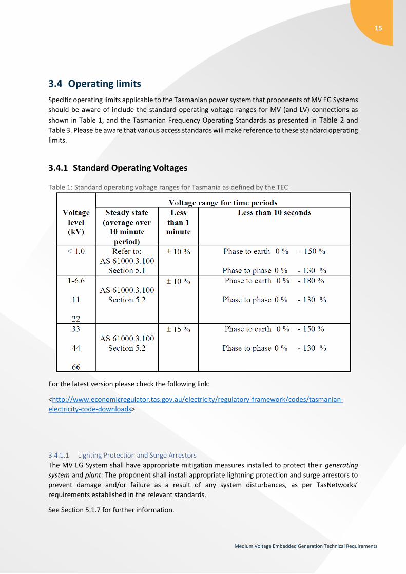
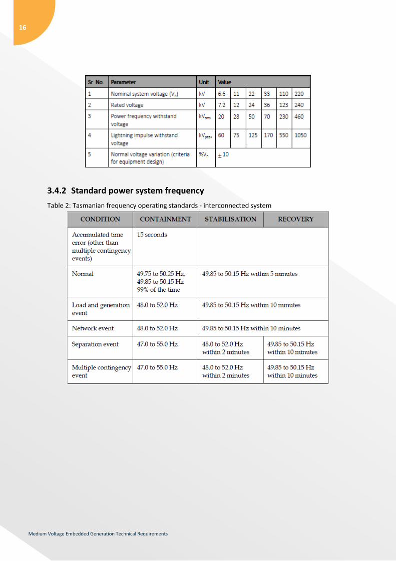
3.4 Operating limits
Specific operating limits applicable to the Tasmanian power system that proponents of MV EG Systems
should be aware of include the standard operating voltage ranges for MV (and LV) connections as
shown in Table 1, and the Tasmanian Frequency Operating Standards as presented in Table 2 and
Table 3. Please be aware that various access standards will make reference to these standard operating
limits.
3.4.1 Standard Operating Voltages
Table 1: Standard operating voltage ranges for Tasmania as defined by the TEC
For the latest version please check the following link:
<http://www.economicregulator.tas.gov.au/electricity/regulatory-framework/codes/tasmanian-
electricity-code-downloads>
3.4.1.1 Lighting Protection and Surge Arrestors
The MV EG System shall have appropriate mitigation measures installed to protect their generating
system and plant. The proponent shall install appropriate lightning protection and surge arrestors to
prevent damage and/or failure as a result of any system disturbances, as per TasNetworks’
requirements established in the relevant standards.
See Section 5.1.7 for further information.
16
Medium Voltage Embedded Generation Technical Requirements
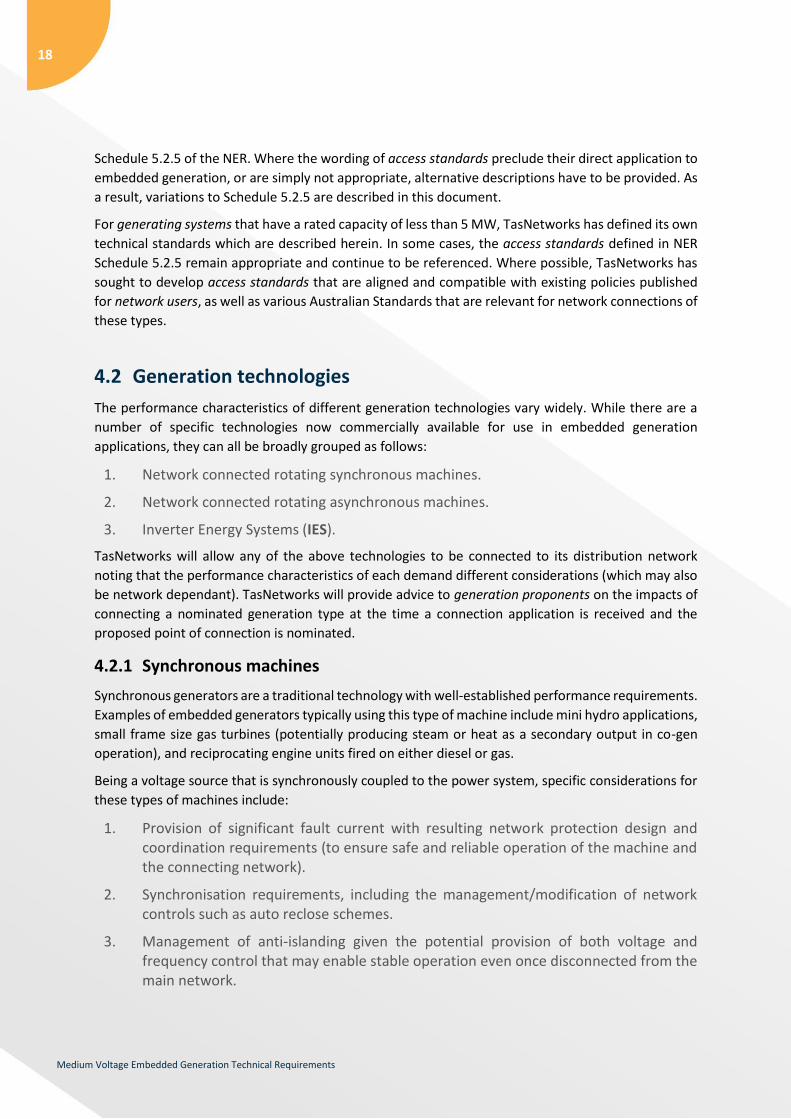
3.4.2 Standard power system frequency
Table 2: Tasmanian frequency operating standards - interconnected system

17
Medium Voltage Embedded Generation Technical Requirements
Table 3: Tasmanian frequency operating standards - islanded system
Table 3 applies when an electrical island is formed within the Tasmanian power system and should not
be interpreted as operation of the Tasmanian system operating as an island within the NEM, i.e. during
periods of time when the Basslink interconnector is out of service.
4 Classification of generation
4.1 Access standards for generators exempt from registration
The National Electricity Law (NEL) requires a person intending to participate in the NEM as a generator
to register with AEMO. In order to obtain approval to physically connect to the power system,
generation proponents must follow the connection process as detailed in Chapter 5 of the NER
including satisfaction of all technical requirements outlines in Schedule 5.2. In this Schedule, access
standards for the connection of generation into a distribution or transmission network are defined.
In accordance with AEMO’s “Guide to Generator Exemptions and Classification of Generating Units”4,
generation proponents may seek a registration exemption from AEMO. AEMO may grant an exemption
when it believes that the generating system is not likely to have a material impact on the operation of
the NEM, or on the activities of other Market Participants. AEMO offers standing exemptions to
generating systems that meet the following criteria:
1. Generating systems that have a rated nameplate rating of less than 5 MW.
2. Generating systems that have a nameplate rating ≥ 5 MW, but do not have the capability to export more than 5 MW to the network.
Generating systems that have a nameplate rating ≥ 5 MW, but do not export more than 20 GWh per
annum to the network, may also be granted exemption upon application.
For generating systems in excess of 5 MW that have sought and been granted exemption from
registration, TasNetworks generally considers it appropriate to apply the access standards provided in
4 AEMO’s Guide to Generator Exemptions and Classification of Generating Units can be accessed here: External Procedures Template Mar 2015 (aemo.com.au)
18
Medium Voltage Embedded Generation Technical Requirements
Schedule 5.2.5 of the NER. Where the wording of access standards preclude their direct application to
embedded generation, or are simply not appropriate, alternative descriptions have to be provided. As
a result, variations to Schedule 5.2.5 are described in this document.
For generating systems that have a rated capacity of less than 5 MW, TasNetworks has defined its own
technical standards which are described herein. In some cases, the access standards defined in NER
Schedule 5.2.5 remain appropriate and continue to be referenced. Where possible, TasNetworks has
sought to develop access standards that are aligned and compatible with existing policies published
for network users, as well as various Australian Standards that are relevant for network connections of
these types.
4.2 Generation technologies
The performance characteristics of different generation technologies vary widely. While there are a
number of specific technologies now commercially available for use in embedded generation
applications, they can all be broadly grouped as follows:
1. Network connected rotating synchronous machines.
2. Network connected rotating asynchronous machines.
3. Inverter Energy Systems (IES).
TasNetworks will allow any of the above technologies to be connected to its distribution network
noting that the performance characteristics of each demand different considerations (which may also
be network dependant). TasNetworks will provide advice to generation proponents on the impacts of
connecting a nominated generation type at the time a connection application is received and the
proposed point of connection is nominated.
4.2.1 Synchronous machines
Synchronous generators are a traditional technology with well-established performance requirements.
Examples of embedded generators typically using this type of machine include mini hydro applications,
small frame size gas turbines (potentially producing steam or heat as a secondary output in co-gen
operation), and reciprocating engine units fired on either diesel or gas.
Being a voltage source that is synchronously coupled to the power system, specific considerations for
these types of machines include:
1. Provision of significant fault current with resulting network protection design and coordination requirements (to ensure safe and reliable operation of the machine and the connecting network).
2. Synchronisation requirements, including the management/modification of network controls such as auto reclose schemes.
3. Management of anti-islanding given the potential provision of both voltage and frequency control that may enable stable operation even once disconnected from the main network.
19
Medium Voltage Embedded Generation Technical Requirements
The correct specification of voltage control requirements can be particular important for synchronous
machines especially at weak connection points. Utilising the inherent capability of a synchronous
machine to control voltage can avoid issues in the network and enable the integration of embedded
generation at locations that may otherwise be prohibitive.
4.2.2 Asynchronous (induction) machines
Asynchronous generators are also a very well understood and a relatively common technology. Typical
examples for embedded generator applications include use in micro and mini hydro units and wind
turbines applications where input power is variable or difficult to control. The ability to operate
induction generators at variable speed (slip) makes them ideal for such circumstances, reducing
control requirements quite considerably in some situations.
Induction generators require an external source of excitation and always absorb reactive power at
their stator terminals (with the exception of doubly fed induction generators which are typically used
in larger wind turbine applications). As such, the connection of this type of generating system requires
consideration of issues which include:
1. Power factor operating range at the connection point and the impact on local distribution network voltage profile. The need for local reactive support to be installed with the generator is one potential solution to this issue if not offered as standard. This arrangement is sometimes referred to as a “self-excited” induction generator.
2. Starting arrangements for the generator, i.e.: the use of direct online (DOL) starting as an induction motor may not be possible at weak connection points due to the high inrush currents involved. “Soft starting” arrangements may require consideration if not offered as standard.
3. The response of the generating system to islanding situations and the possibility of self-excitation. The issue to be managed is the risk of continued operation for a period of time even once disconnected from the main network.
Depending on the size of the generating unit, the provision of transient fault currents may also be a
relevant consideration. An induction generator will feed current into a fault until such time that its
internal magnetic field has collapsed causing de-excitation of the machine.
While induction generators are typically lower cost and have simpler control and protection
arrangements, their connection to the distribution network still requires due consideration of potential
issues so that network safety and performance can be managed.
4.2.3 Inverter energy systems
Inverter Energy Systems (IES) use power electronics to convert electrical power from either direct
current (DC), or a variable frequency alternating current (AC) waveform, to a 50 Hz AC supply which
allows connection to the main network.
20
Medium Voltage Embedded Generation Technical Requirements
IES EG Systems may either be line commutated or self-commutated technologies. Line commutated
inverter systems typically use power electronic devices such as thyristors and rely on the mains voltage
signal as a reference for commutation. Self-commutated inverter systems use an internal high
frequency reference signal for control of power electronics (IGBT, MOSFET etc.) typically implementing
Pulse Width Modulation (PWM).
Static generating devices (such as PV panels), as well as rotating plant, can be connected to the grid
via an inverter. For the latter, this is generally preferable for small installations because of the
additional control that is possible via the inverter, especially in relation to the management of
connection point power factor and/or voltage.
In terms of connection point issues to be considered, the impact on network voltage control and anti-
islanding protection is as per the other generation types already mentioned. In addition, inverter
connected generating systems can potentially introduce power quality issues including harmonic
distortion and flicker, depending on the generating system’s size and inverter type being used.
5 Technical requirements
5.1 Generator performance access standards
For MV EG Systems, TasNetworks generally considers it appropriate to apply the access standards
provided in Schedule 5.2.5 of the NER. Where the wording of access standards preclude their direct
application to embedded generation, or are simply not appropriate, alternative descriptions have to
be provided. As a result, variations to Schedule 5.2.5 are described in this document.
In a similar manner to that utilised within the NER, the access standards applied by TasNetworks for
the connection of EG generally fall into one of three categories:
Automatic Access: A generating system that meets such a standard would not be unreasonably
denied access to the distribution network.
Negotiated Access: A generating system that can be demonstrated to satisfy defined minimum
access standards, but is unable (for whatever reason) capable of satisfying all
automatic access standards, may still be granted a network connection subject
to technical review and approval by TasNetworks.
It should be noted that the size and type of generating system to be connected
will be taken into consideration to ensure that negotiated access standards
are appropriate and relevant for the connection arrangements being
proposed.
Minimum Access: Failure to meet a described minimum access standard will result in the
generation proponent being refused access to the distribution network.
When considering a negotiated access standard, the proponent is expected to be as close as
practicable to the automatic access standard. TasNetworks therefore considers that the automatic
21
Medium Voltage Embedded Generation Technical Requirements
access standard is the default starting position for negotiations for connections. Where an automatic
access standard is not possible or is not required, the proponent must adequately demonstrate why
the proposed negotiated access standard is considered adequate.
In all cases, TasNetworks will require the submission of suitable information from the generation
proponent to enable technical assessments to be undertaken, including the need for any negotiated
access arrangements, as well as evidence that all minimum access standards have been satisfied (See
Section 6). Steady stage and dynamic modelling studies may also be required to be submitted by the
generation proponent demonstrating compliance against the NER access standards.
The MV EG System (also referred to as the generating system where appropriate) is expected to
comply with the following (reduced set) of NER generator performance access standards:
S5.2.5.1 – Reactive Power Capability
S5.2.5.2 – Quality of electricity generated
S5.2.5.3 – Generating unit response to frequency disturbances
S5.2.5.4 – Generating system response to voltage disturbances
S5.2.5.5 – Generating system response to disturbances following contingency events
S5.2.5.6 – Quality of electricity generated and continuous uninterrupted operation
S5.2.5.8 – Protection of generating systems from power system disturbances
S5.2.5.9 – Protection systems that impact on power system security
S5.2.5.10 – Protection to trip plant for unstable operation
S5.2.5.11 – Frequency Control
S5.2.5.12 – Impact on network capability
S5.2.5.13 – Voltage and reactive power control
S5.2.5.14 – Active Power Control
S5.2.8 – Fault Current
5.1.1 Reactive power capability and power factor requirements (S5.2.5.1)
TasNetworks requires that the MV EG System have sufficient reactive capability to maintain voltage at
the connection point within prescribed limits.
The proponent is expected to provide the reactive power capability of the MV EG System from 0% to
100% active power output over a connection point voltage range from 90% to 110% of nominal voltage.
For MV EG Systems that are equal to or larger than 5 MW in capacity, TasNetworks considers the access
standards defined in S5.2.5.1 of the NER to be appropriate. The MV EG System should ideally be
capable of supplying and absorbing reactive power equal to the product of the rated active power and

22
Medium Voltage Embedded Generation Technical Requirements
0.395. This should be possible across the full range of active power outputs that the MV EG System
may operate at.
For MV EG Systems that are smaller than 5 MW, operation of the generator at a fixed power factor
may be sufficient to maintain distribution network voltages within acceptable limits. For areas of the
network where this is achievable, TasNetworks requires that the power factor at the connection point
be maintained within the ranges provided in Table 4.
Table 4: Power Factor Operational Limits – Tasmanian Electricity Code (TEC), Table 1
Supply Voltage (kV)
Power factor range for customer maximum demand and voltage
Up to 100 kVA Over 100 kVA – 2 MVA Over 2 MVA
Minimum lagging
Minimum leading
Minimum lagging
Minimum leading
Minimum lagging
Minimum leading
<6.6 0.75 0.8 0.8 0.8 0.85 0.85
6.6 11 22
0.8 0.8 0.85 0.85 0.9 0.9
33 44 66
0.85 0.85 0.9 0.9 0.95 0.98
In weak areas of the network, managing connection point power factor as embedded generation
output varies may not be sufficient to maintain acceptable distribution network voltages.
Under such circumstances, the requirement to regulate network voltages takes precedence. To meet
its regulatory obligations, TasNetworks may require that the MV EG System operate at a power factor
that is different to that permitted in Table 4, or alternatively, may require that the MV EG System
operate in “voltage control mode” so as to provide dynamically controlled voltage support to the
connection point and surrounding network.
The generation proponent must negotiate with TasNetworks to determine the minimum reactive
capability of the MV EG System (that is available for use) and the control requirements necessary to
support its operation at the proposed connection point.
5.1.2 Quality of electricity generated (S5.2.5.2)
The introduction of voltage fluctuations, harmonics or voltage unbalance into the distribution network
may result in the maloperation or damage to electrical equipment operated by other network users.
The impact of a particular development on the quality of supply is dependent on the current drawn or
supplied by the MV EG System and the system impedances at the proposed connection point. To
ensure that the quality of supply remains consistent with TasNetworks’ published planning limits5,
TasNetworks will allocate emission limits to a generation proponent at the time a connection
application is processed.
5 Planning limits are published in TasNetworks Annual Planning Report (APR) - www.tasnetworks.com.au
23
Medium Voltage Embedded Generation Technical Requirements
Acceptable operation requires the MV EG System to comply with the allocated emission limits, which
will always be less than the published planning limits.
To determine these values, TasNetworks requires a generation proponent to specify the proposed
connection point and the rating of the MV EG System at the connection enquiry stage.
5.1.2.1 Voltage fluctuations
The contribution of an MV EG System to flicker and transient voltage deviations is dependent on the
magnitude of change in the current supplied/drawn, and the equivalent impedance at that point in the
network.
For MV EG Systems, TasNetworks considers it appropriate to apply the access standards defined in
S5.2.5.2 of the NER. This clause refers to emission limits (S5.1.5 of the NER) that may be calculated
using AS/NZS 61000.3.7:2001 and guidelines published by Standards Australia, i.e. ENA Doc 034-2014
Guideline for Power Quality – Flicker (Recommendation for the application of joint Australian/ New
Zealand Technical Report TR IEC 61000.3.7:2012).
Once a connection application is received, TasNetworks will determine which assessment stage (as
defined in the standard) to apply based on the size of the MV EG System and the short circuit capacity
at the proposed connection point.
5.1.2.2 Harmonic injection limits
The impact of an MV EG System on harmonic voltages in the network is dependent on the harmonic
currents drawn or supplied through the connection point and the equivalent harmonic impedances at
that point in the network.
For all MV EG System, TasNetworks considers the access standards defined in S5.2.5.2 of the NER to
be appropriate. The schedule refers to standard limits that may be calculated using AS/NZS
61000.3.6:2001 and guidelines published by Standards Australia, i.e. ENA Doc 033-2014 Guideline for
Power Quality – Harmonics (Recommendation for the application of joint Australian/ New Zealand
Technical Report TR IEC 61000.3.6:2012).
Once a connection application is received, TasNetworks will determine which assessment stage (as
defined in the standard) to apply based on the size of the MV EG System and the short circuit capacity
of the proposed connection point.
5.1.2.3 Voltage unbalance
To comply with the requirements of Schedule 5.1a.7 of the NER, TasNetworks must actively manage
voltage unbalance in both the distribution and transmission networks.
At distribution level voltages relevant for the connection of MV EG System, TasNetworks considers
performance to be adequate if the current in any phase measured across a three phase connection
point is not greater than 102 percent or less than 98 percent of the average of the currents in the three
phases.
If the generation proponent cannot satisfy these requirements, TasNetworks considers it appropriate
to determine unbalance requirements in accordance with IEC Technical Report TR IEC 61000.3.13 and
the guideline published by Standards Australia (ENA Doc 037-2015 Guideline for Power Quality –
24
Medium Voltage Embedded Generation Technical Requirements
Voltage Unbalance (Recommendation for the application of joint Australian/ New Zealand Technical
Report TR IEC 61000.3.13:2013).
5.1.2.4 Zero sequence generation
The introduction of zero sequence currents into the MV network may have adverse effects on the
balancing of phase loadings and the operation of earth fault protection. Please refer to section 5.10
for further requirements for the physical connection of three phase equipment.
5.1.3 Generating unit response to frequency disturbances (S5.2.5.3)
To prevent the cascading disconnection of embedded generation during and following a network
frequency disturbance (with the resulting impacts that this would have on the broader power system),
it is expected that MV EG System shall comply with the following performance requirements.
For MV EG Systems that are equal to or larger than 5 MW, TasNetworks will apply the access standards
as defined in Schedule 5.2.5.3 of the NER.
MV EG Systems that are smaller than 5 MW in capacity shall not disconnect from the network when
frequency is within the range 47.0 Hz to 52.0 Hz unless one or more anti-islanding protection schemes
has determined that the generator has become electrically separated from the main network supply.
Anti-islanding protection is discussed further in Section 5.2.5.9.
In all cases, TasNetworks will review and negotiate the setting of under and over frequency protection
so as to ensure coordination with other network protection and control schemes.
5.1.4 Generating unit response to voltage disturbances (S5.2.5.4)
When a voltage disturbance occurs in the power system, the recovery of voltage to the normal
operating range is (generally) achieved through the clearance of the network fault that has caused the
initial voltage disturbance. To ensure that the power system is robust to system events, it is therefore
important that generators remain connected until at least primary protection has operated to clear
the fault. Schedule 5 of the NER specifies the maximum clearance time for transmission network fault
events to be 120 ms.
Transmission fault events are a critical consideration given that wide areas of the network may suffer
from a depressed voltage profile as a result, placing at risk significantly more embedded generating
systems (as compared to a local distribution network fault event).
For MV EG Systems that are equal to or larger than 5 MW, TasNetworks will apply the access standards
defined in Schedule 5.2.5.4 of the NER.
For MV EG Systems that are smaller than 5 MW, the generating system shall maintain continuous
uninterrupted performance and shall not disconnect from the network within 150 ms for any voltage
disturbance. After 150 ms, the generating system may disconnect if the voltage remains outside of the
operational voltage ranges for the corresponding time periods as defined in Section 8.6.4 of the TEC
(refer Section 3.4, Table 1).
25
Medium Voltage Embedded Generation Technical Requirements
The proponent may be asked to provide time domain studies demonstrating the generating system’s
ability to remain in continuous uninterrupted operation for a range of connection point voltages and
operating conditions for which the generating system is expected to ride through.
5.1.5 Generating response to disturbances following contingency events
(S5.2.5.5)
When a network contingency event occurs, the recovery of the system to its pre-contingency operating
state is (generally) achieved through the automatic control of generators (as well as other network
devices) that remain connected to the power system. To ensure that the power system is robust to
system events, it is therefore important that generating systems perform in a predictable manner in
the post contingency period. Furthermore, generating systems should not unreasonably withdraw
their available capacity for significant periods of time given the power imbalance that is then inflicted
on the remainder of the power system.
For MV EG Systems that are equal to or larger than 5 MW, TasNetworks will apply the access standards
defined in Schedule 5.2.5.5 of the NER.
For MV EG Systems that are smaller than 5 MW, TasNetworks requires that a generating system be
capable of supplying 95% of its pre-fault power within 500 ms of a fault being cleared by protection
systems. If this requirement cannot be met, then the generation proponent must enter a process of
negotiation with TasNetworks.
Where a MV EG System is capable of providing frequency control capability within this time frame, and
does so in response to an over frequency condition, this characteristic shall take precedence over the
active power recovery criteria discussed above.
The proponent may be asked to provide time domain studies demonstrating the generating system’s
ability to remain in continuous uninterrupted operation and fault response for a range of network
faults described in Clause S5.2.5.5 of the NER - including multiple faults. The studies are expected to
demonstrate performance across a range of active power generation and operating conditions
(maximum and minimum reactive output) taking into consideration maximum and minimum fault level
at the connection point.
5.1.6 Quality of electricity generated and continuous uninterrupted
operation (S5.2.5.6)
Generators should recognise that certain parameters within the power system are permitted to vary
from ideal under normal system operating conditions. This includes voltage magnitude, frequency,
flicker levels, harmonic distortion and voltage unbalance (across phases). Generating systems should
be robust to variations within permissible limits.
For all generating systems, TasNetworks requires compliance with the minimum access standard
defined in Schedule 5.2.5.6 of the NER.

26
Medium Voltage Embedded Generation Technical Requirements
It is expected that the proponent provide confirmation that the generating system will remain in
continuous uninterrupted operation for the levels specified in clauses S5.1a.5, S5.1a.6 and S5.1a.7 of
the NER.
TasNetworks publishes its power quality planning limits in its Annual Planning Report which is available
on its website.
5.1.7 Protection of generating systems from power system disturbances
(S5.2.5.8)
To maintain network security and reliability, it is important that generating systems do not disconnect
from the network for operating conditions that remain within their stated capability. All generating
systems are expected to maintain continuous, uninterrupted operation except when exposed to
abnormal power systems conditions that have been accepted to by TasNetworks. The generating
system shall have sufficient systems in place that disconnect and prevent damage to the generating
system in the event of any abnormal power system conditions.
For MV EG Systems that are equal to or larger than 5 MW, TasNetworks requires compliance with the
minimum access standard and general requirements defined in Schedule 5.2.5.8 of the NER.
Refer to Section 5.2 for further information.
5.1.8 Protection systems that impact on power system security (S5.2.5.9)
Refer to Section 5.2 for further information.
5.1.9 Protection to trip plant for unstable operation (S5.2.5.10)
To prevent sustained, unstable behaviour of a generating system impacting other network users,
suitable protection must be installed to disconnect the generating system when its operation becomes
abnormal.
TasNetworks considers the access standards defined in Schedule 5.2.5.10 of the NER to be appropriate
for generating systems of all sizes.
For synchronous machines refer also to Section 5.2.5.8.
5.1.10 Frequency control (S5.2.5.11)
While AEMO is directly responsible for managing power system frequency, which it does via purchase
of Frequency Control Ancillary Services (FCAS) from the eight spot markets which exist in the NEM,
embedded generating systems also have a role to play.
This is especially true in a small power system such as Tasmania, where frequency control has
traditionally been more challenging.

27
Medium Voltage Embedded Generation Technical Requirements
For MV EG Systems that are equal to or larger than 5 MW in capacity, TasNetworks will apply the access
standards defined in Schedule 5.2.5.11 of the NER.
For MV EG Systems smaller than 5 MW, the expectations of TasNetworks are as follows:
1. Where practical to do so, all generating systems should provide frequency control capabilities and be responsive to network frequency disturbances. A speed droop characteristic equivalent to 4% (as would be defined for governor control systems installed on synchronous machines) is considered typical and adequate.
The impact that frequency control capabilities may have on anti-islanding protection arrangements will be considered during the connection application assessment process.
2. Where normal operation of the generating system naturally inhibits any increase in active power output to support the system recovery from under frequency events, consideration should still be given to the control of over frequency conditions. For such circumstances, a controlled reduction in active power output proportional to frequency deviation is beneficial.
3. All generating systems should comply with the minimum access standard defined by Schedule 5.2.5.11 of the NER, taking into account the active power recovery characteristics immediately post fault as defined in Section 5.1.5 (S5.2.5.5) of this guideline.
All frequency control systems installed as part of a generating system should be adequately damped
as defined by the NER, i.e. the controller’s response to a frequency deviation should be tuned to
prevent oscillatory behaviours and/or excessive overshoot that may be counterproductive to the
stable recovery of system frequency.
5.1.11 Impact on network capability (S5.2.5.12)
To facilitate efficient operation of the energy market in the Tasmanian region, TasNetworks requires
that inter-regional and intra-regional power transfer capabilities are not adversely affected by the
connection of embedded generation into the distribution network.
For MV EG Systems equal to or larger than 5 MW, TasNetworks will apply the access standards defined
in Schedule 5.2.5.12 of the NER. This will in most cases require a basic review of perceived risk based
on the size of the generating system and the connection point to the network. Detailed studies would
only be undertaken if deemed necessary based on the initial assessment.
For MV EG Systems smaller than 5 MW, it is considered unlikely that there will be material impacts on
power transfer capabilities at the transmission system level. A cursory examination of any potential
issues will be undertaken as part of the connection application

28
Medium Voltage Embedded Generation Technical Requirements
5.1.12 Voltage and reactive power control (S5.2.5.13)
To ensure that network voltages can be effectively managed, all generating systems comprised of
synchronous machines, doubly fed induction generators or inverter interfaced energy sources should
be fitted with appropriate control systems that allow voltage, reactive power and power factor at the
generating systems terminals to be dynamically controlled.
For induction generators, the requirement for independent control of switched capacitor banks or
other forms of reactive compensation will be determined as part of the connection application
assessment process.
The selection of an appropriate control arrangement will be dependent on the size of the generating
system and the proposed connection point to the distribution network. The specification of control
requirements will occur in conjunction with TasNetworks.
In relation to dynamic response requirements, for MV EG Systems greater than or equal to 5 MW,
TasNetworks will apply the access standards defined in Schedule 5.2.5.13 of the NER.
For MV EG Systems less than 5 MW, TasNetworks will apply the performance requirements stipulated
in Schedules S5.2.5.13 (b)(2B), S5.2.5.13 (b)(3) and S5.2.5.13 (b)(4) of the NER as the appropriate
automatic access standard. Schedules S5.2.5.13 (d)(2A), S5.2.5.13 (d)(2B) and S5.2.5.13 (d)(3) of the
NER will be referenced as the corresponding minimum access standard.
The specified sections of the NER are consistent with the general expectations described above and
have the intent of providing sufficient control capability such that TasNetworks can continue to
manage its regulatory obligations once the generating system is connected to the distribution network.
5.1.13 Active power control (S5.2.5.14)
From time to time, EG Systems may be requested by TasNetworks to reduce their active power output
or disconnect in response to network maintenance, testing, network overloads, safety, islanding,
system security or network stability. To meet the requirements of S5.2.5.14, all MV EG System will be
required to automatically reduce their active power output following receipt of such a signal. The
active power output will need to be linearly reduced or in 10% steps over a five minute period.
For MV EG Systems less than 5 MW, TasNetworks will apply the performance requirements stipulated
in S5.2.5.14(a)(2) of the NER as the appropriate automatic access standard. Schedule S5.2.5.14 (b)(2)
of the NER will be referenced as the corresponding minimum access standard and will only be
considered by TasNetworks in circumstances where appropriate communications facilities are not
available.
For all generating systems that have the ability to export greater than or equal to 5 MW into the HV
transmission network, TasNetworks will require that the generating system be scheduled/semi-
scheduled and will apply the access standards defined in Schedule 5.2.5.14 of the NER.

29
Medium Voltage Embedded Generation Technical Requirements
5.2 Protection requirements
5.2.1 General
To ensure safe and reliable operation of the distribution network, appropriate protection must be
fitted by MV EG Systems. In the design of protection schemes, consideration must be given to the
requirements of the MV EG System, the network in the vicinity of the connection point, and the
protection schemes that are already in place within the broader distribution network.
Communication and negotiation with TasNetworks will almost certainly be required to develop
protection schemes that grade appropriately and provide adequate coverage (especially in the case of
backup protection). It is important that the MV EG System’s protection is able to identify and isolate
all internal faults, and network faults beyond the connection point, as agreed with TasNetworks.
As a general requirement, MV EG System shall have sufficient protection systems that disconnect and
prevent damage to the generating system in the event of a power system disturbance.
Although all MV EG Systems must meet certain minimum protection requirements, the level of
protection required will depend on the specific nature of the MV EG System. This section aims to
provide clarification on the specific protection requirements for MV EG Systems of different
technologies and sizes.
In general, for MV EG System that are equal to or larger than 5 MW in capacity, TasNetworks will apply
the access standards defined in Schedule 5.2.5.9 of the NER. For all generating systems, the following
issues and considerations will be assessed by TasNetworks as part of the connection application
process.
5.2.2 Protection system design philosophy
TasNetworks requires MV EG Systems to implement protection systems to ensure that all faults are
cleared, even with the failure or maloperation of a single protection element. It is recommended that
the relays utilised for main and backup protection are sourced from different manufacturers, and
where reasonable to do so, utilise separate CT cores and VT windings as their input signals.
Where the proponent does not believe it practical to install duplicate protection, the design of the
protection system will take place through a collaborative process with TasNetworks. TasNetworks’
Approval will be required in regards to the provision of backup protection from network installed
protection devices, either existing or new.
In all cases, the determination of protection zones and available protection overlap will need to be
considered for forward and reverse power flow conditions to ensure that faults of all types can be
identified and cleared. A specific consideration is the ability of the MV EG System to detect and respond
to earth faults in an unearthed electrical island, as may occur following upstream protection and circuit
breaker operations.
30
Medium Voltage Embedded Generation Technical Requirements
5.2.3 Protection operating speed
Failure to clear electrical faults in an appropriate time represents a potential safety risk to network
users and the general public, can result in damage to equipment, and reduces the quality and reliability
of power supply.
Generators should provide TasNetworks with expected protection operating times so that
TasNetworks may:
1. Undertake protection coordination studies to assess what discrimination exists between overlapping protection devices. A review of proposed relay settings and expected circuit breaker operating times may be sufficient in many circumstances.
2. Confirm that protection operating times for faults within the generating system are consistent with existing network design philosophies.
3. Confirm that protection operating times do not result in a degradation of network reliability that would subsequently affect other network users.
As a general design rule, faults within the generating system should be cleared as quickly as possible,
whereas faults remote from the generating system should be cleared in a manner that minimises
disruption to other network users, i.e. occurs in a coordinated manner taking into account the
operation of other network protection.
For faults external to the generating system, i.e. in the distribution network, installed protection
devices must identify and isolate the fault from both the point of network supply as well as the
generating system supply point. This applies to faults of any type.
To achieve discrimination between internal and external faults, it is recommended that the main
incoming circuit breaker protection devices have directional protection capabilities. The generation
proponent should consult with TasNetworks to determine the necessity for their particular installation.
Where the upstream protection device is a fast operating device such as a fuse, grading may not be
appropriate or practical. In these instances, the generation proponent should demonstrate to
TasNetworks that all practical steps have been made to grade the installed protection. TasNetworks
may consider slowing the upstream protection if it believes it is necessary to prevent internal
generating system faults from affecting other network users. However, if distribution protection must
be slowed beyond threshold values that TasNetworks considers acceptable, it may be necessary to
implement a blocking scheme to facilitate protection coordination.
5.2.4 Inverter integrated protection
Inverter integration protection shall include the following:
1. Under and over voltage protection
2. Under and over frequency protection
3. Active anti-islanding protection
4. Phase balance protection (where applicable)
5. Synchronisation facilities (where applicable)
31
Medium Voltage Embedded Generation Technical Requirements
Where applicable, inverter integrated protection requirements should preferably be as per AS/NZS
4777.2.
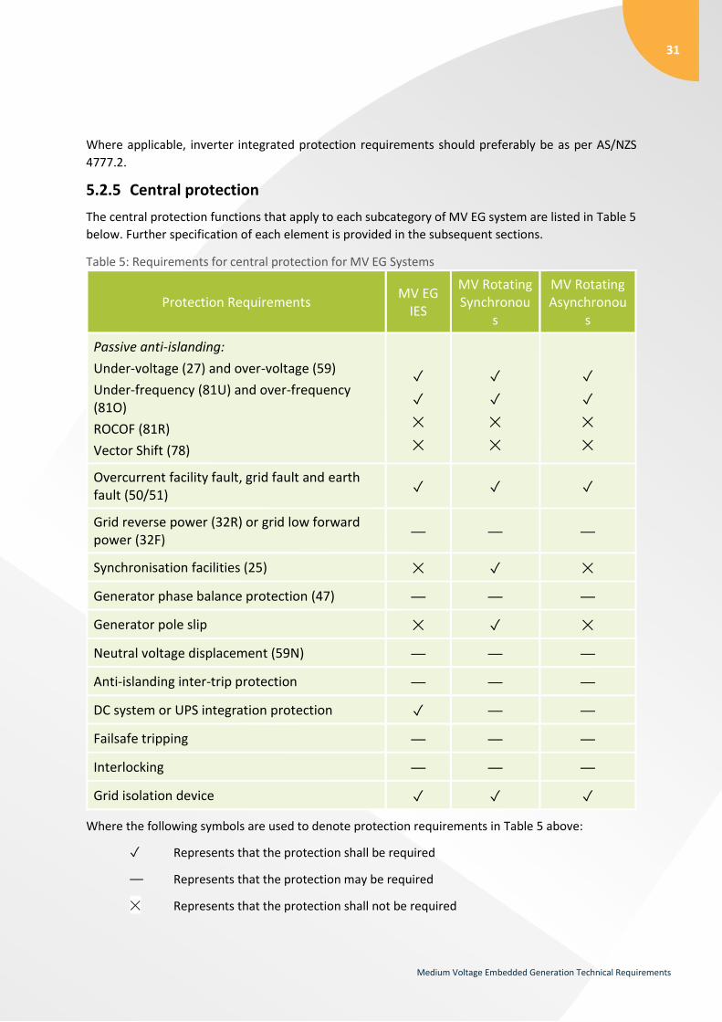
5.2.5 Central protection
The central protection functions that apply to each subcategory of MV EG system are listed in Table 5
below. Further specification of each element is provided in the subsequent sections.
Table 5: Requirements for central protection for MV EG Systems
Protection Requirements MV EG
IES
MV Rotating Synchronou
s
MV Rotating Asynchronou
s
Passive anti-islanding:
Under-voltage (27) and over-voltage (59)
Under-frequency (81U) and over-frequency (81O)
ROCOF (81R)
Vector Shift (78)
✓
✓
✕
✕
✓
✓
✕
✕
✓
✓
✕
✕
Overcurrent facility fault, grid fault and earth fault (50/51)
✓ ✓ ✓
Grid reverse power (32R) or grid low forward power (32F)
⏤ ⏤ ⏤
Synchronisation facilities (25) ✕ ✓ ✕
Generator phase balance protection (47) ⏤ ⏤ ⏤
Generator pole slip ✕ ✓ ✕
Neutral voltage displacement (59N) ⏤ ⏤ ⏤
Anti-islanding inter-trip protection ⏤ ⏤ ⏤
DC system or UPS integration protection ✓ ⏤ ⏤
Failsafe tripping ⏤ ⏤ ⏤
Interlocking ⏤ ⏤ ⏤
Grid isolation device ✓ ✓ ✓
Where the following symbols are used to denote protection requirements in Table 5 above:
✓ Represents that the protection shall be required
⏤ Represents that the protection may be required
✕ Represents that the protection shall not be required

32
Medium Voltage Embedded Generation Technical Requirements
5.2.5.1 Passive anti-islanding protection
TasNetworks requires that all MV EG Systems have the following passive anti-islanding protection:
1. Under and over voltage 2. Under and over frequency limits
TasNetworks requires that no Rate of Change of Frequency (ROCOF) or Vector Shift protection be
enabled for the purposes of passive anti-islanding as a part of the central protection. Where required,
TasNetworks will also require the EG System to implement a communications-based Anti-islanding
inter-trip protection.
The protection settings for the passive anti-islanding protection must take into consideration the
performance requirements for voltage and frequency as specified in Sections 5.1.3 and 5.1.4. The
default recommended passive anti-islanding protection settings are shown in the and Table 8 below.
TasNetworks reserves the right to apply variations to the values below following an assessment of each
individual EG System.
Table 6: TasNetworks’ default Passive Anti-Islanding Protection Settings for IES
Passive Anti-Islanding Protection Setting Value Delay
(Seconds)
Over Voltage (V>) 115% 10
Over Voltage (V>>) 120% -
Under Voltage (V<) 80% 5
Under Voltage (V<<) 30% 1.0
Over Frequency (F>) 53 Hz -
Under Frequency (F<) 45 Hz 1.0
Table 7: TasNetworks’ default Passive Anti-Islanding Protection Settings for rotating machines (synchronous and asynchronous)
Passive Anti-Islanding Protection Setting Value Delay
(Seconds)
Over Voltage (V>) 115% 3.0
Over Voltage (V>>) 130% 0.1
Under Voltage (V<) 90% 20.0
Under Voltage (V<<) 75% 1.0
Over Frequency (F>) 52 Hz 0.1
Under Frequency (F<) 47 Hz 1.0

33
Medium Voltage Embedded Generation Technical Requirements
5.2.5.2 Protection of grid from faults within the generating system
TasNetworks requires that any fault internal to the embedded generating system is identified and
isolated from the distribution network as fast as is practical. This is to ensure that distribution
protection does not operate unnecessarily, resulting in loss of supply to other network users. To detect
internal faults, any reliable techniques may be used. These may include, but are not limited to:
1. Differential protection
2. Overcurrent protection
3. Earth fault protection (including sensitive earth fault (SEF))
MV EG Systems must attempt to grade the generating system protection with upstream protection
with a clearance margin of 250 ms.
The generator must be capable of identifying and clearing high impedance phase to ground faults,
internal to the generating system. Where the generator is connected to the network through a step-
up transformer, protection of the generator side windings may be achieved through conventional
earth fault protection methods and technologies. Discussion on protection of the network side of the
transformer (or if the generator is connected directly to the distribution network) is discussed further
below.
5.2.5.3 Detection of faults external to the generating system
For synchronous and asynchronous rotating generators, the exact settings will be determined by
negotiation with TasNetworks.
IES no requirements.
5.2.5.4 Grid reverse power or grid low forward power protection
Where rotating machines lose their supply of mechanical power, they will naturally transition into
motoring mode and begin drawing active power from the network. It is recommended that rotating
machines be installed with reverse power flow protection to disconnect under such conditions.
For all non-exporting MV EG Systems, directional flow protection at the point of connection to trip
non-exporting machines if they begin to export shall be required to be installed.
5.2.5.5 Synchronisation facilities
The following automatic synchronising and synchronisation check requirements shall be required
where it is intended that operation of any EG unit will occur:
1. MV EG IES connections shall comprise inverters with internal synchronisation facilities
2. MV EG rotating synchronous generators shall implement a synchronism check at the generator circuit breaker.
3. MV EG rotating asynchronous generators do not require synchronization facilities.
5.2.5.6 Generator phase balance protection
TasNetworks has no requirements for the implementation of current or voltage unbalance protection.

34
Medium Voltage Embedded Generation Technical Requirements
The proponent must ensure that its generating system is capable of meeting the generator
performance standards outlined in Section 5.1.2.3. It is assumed that all MV EG Systems will be three
phase connections.
5.2.5.7 Neutral voltage displacement
Where a direct inter-trip scheme is not implemented, the protection design must consider a
mechanism to trip the generator for earth faults on the MV distribution network. Neutral voltage
displacement protection is the recommended method to trip the generator in this scenario.
5.2.5.8 Pole Slip Protection
Pole slip protection shall be required to be installed for synchronous MV EG Systems to disconnect the
generating system upon detection of a loss of synchronism.
5.2.5.9 Anti-islanding Inter-trip protection
Electrical islanding (in the distribution network) is the process where a sub-section of the network is
disconnected from other sources of generation (through fault or other network switching events), but
remains energised via embedded generating system(s) connected in the local area.
Two fundamental conditions must exist if a viable electrical island is to form:
1. The embedded generating system(s) can continue to operate as a voltage source without the normal network supply being present.
2. The load and generation in the islanded section of the network can achieve equilibrium such that load demand is balanced by generation capability.
Please refer to TasNetworks’ Embedded Generation Anti-Islanding Standard (see Section 3.1) for anti-
islanding protection requirements.
5.2.5.10 DC system or UPS integration protection
The EG System shall be automatically disconnected where a failure in the DC system supply or
Uninterruptible Power Supply (UPS) supply to the central protection and control systems is detected.
Where there is a failure in the DC system supply or UPS supply to the High Voltage (HV) incomer
relay protection, an alarm shall automatically be issued and the EG system should not be
disconnected.
5.2.5.11 Failsafe tripping
Failsafe tripping may be determined to be required depending on the outcomes of a site-specific
assessment by TasNetworks.
5.2.5.12 EG system grid isolation device
TasNetworks requires a circuit breaker to be installed as close as practical to the connection point of
the MV EG System. The grid isolation device may therefore be required to disconnect not only the
generator, but also any additional primary equipment that may form part of the generating system,
e.g. a step-up transformer.
The EG System grid isolation device shall be owned by the proponent.

35
Medium Voltage Embedded Generation Technical Requirements
TasNetworks will install its own network isolation device (See Section 5.9) upstream of the connection
point for operational purposes. TasNetworks’ network isolation device shall not be used to provide any
central protection capability or services for the MV EG System. A separate disconnect device for the
purposes of anti-islanding inter-tripping may be installed by TasNetworks.
5.2.6 Generator connection and disconnection
The connection and disconnection process for MV EG Systems should be performed, as far as
practicable, in a way that minimises the impact on other network users. The exact requirements for
connection and disconnection of a MV EG System to the distribution network will depend on the
machine type and size.
For example, a large synchronous machine connected to a weak part of the distribution network may
be required to reduce power output below a specified value prior to normal disconnection from the
network.
The requirements for the connection of induction generators to the distribution network shall be
determined after the impact of the generating system on power quality has been considered. As
previously mentioned, the initial starting of induction generators direct-online (DOL) may not be
allowed due to the impact on other network users.
5.2.7 Automatic reclose
TasNetworks utilises reclosers as network protection devices to identify and clear transient faults and
to prevent the unnecessary operation of permanent protection devices such as fuses. Reclosers will
typically attempt three auto close sequences before locking out. In combination with anti-islanding
protection, reclosers and distribution feeder circuit breakers will be required to be configured with
live-load-blocking to prevent out-of-sync closing onto downstream network elements that may have
remained energised from an alternate source. The cost of reconfiguring any upstream reclosers will be
borne by the MV EG System proponent.
Embedded generating systems shall only reconnect to the network when the network has been re-
energised and has remained within the normal operational voltage and frequency limits for a period
of at least five minutes and is approved to do by TasNetworks Operations as per the agreed Joint
Operating Procedure (JOP). This is to ensure that any reclose event has been successful and to
maximise the probability that the embedded generating system will maintain operational after
reconnecting to the network.
5.3 Fault level requirements (S5.2.8)
Unless otherwise agreed in writing between the generation proponent and TasNetworks, the
generation proponent must design its generating system so that it does not cause fault levels in the
distribution system to exceed the values specified in Table 8. In some areas of the network
TasNetworks may require the fault level to be restricted to values below those specified in Table 8.

36
Medium Voltage Embedded Generation Technical Requirements
TasNetworks will advise the generation proponent of any requirements to limit and/or manage fault
level contribution coming from the proposed generating system, at the time of connection application.
Table 8: Maximum allowable network fault level contribution from the transmission to the distribution system at specified voltages.
5.4 Inverter Energy Systems
The following requirements shall apply to IES MV EG Systems
1. IES EG units connected to MV networks shall comprise of inverters that are:
a. If used in solar PV systems: type tested and certified as being compliant with an accreditation number or certificate of suitability as evidence of compliance to IEC 62116 for anti-islanding protection
b. Preferably tested by an authorised testing laboratory and certified as being compliant, with an accreditation number or certificate of suitability as evidence of compliance to AS/NZS 4777.2
c. Preferably be registered with CEC as approved grid connect inverters
d. Preferably installed in compliance to AS/NZS 4777.1 (where applicable)
2. IES EG units shall comprise of inverters that have the following inverter power quality response modes available:
a. Reactive power control mode
b. Central control mode via a master/slave system (i.e Power Park Controller (PPC) or Virtual Plant Controller)
c. Volt response mode (i.e volt-var and volt-watt)
d. Fixed power factor or reactive power mode
e. Power rate limit (i.e ramp rate control)
37
Medium Voltage Embedded Generation Technical Requirements
3. The IES EG system may be required to coordinate the active and reactive power of all inverters through the use of a central PPC. This requirement will be determined during the connection application assessment.
5.5 Monitoring and control requirements
5.5.1 Communications systems
TasNetworks’ preferred communications medium is point-to-point fibre optic for all protection,
control and remote monitoring. Where the implementation of fibre is excessively expensive or
impractical, it may be appropriate for another communications medium to be used.
Protection schemes that rely on communication links must provide continuous monitoring (of the
communication link integrity) and trip the generating system in the event of a communications failure.
The communication protocol for remote monitoring will be of a suitable format to allow integration
with TasNetworks’ existing SCADA system which is based on DNP 3.0.
5.5.2 Power quality monitoring
A power quality meter may be required to be installed at the connection point for some generating
systems at the proponents cost. This will be determined following the submission of a connection
application.
5.5.3 Local monitoring and control
Local monitoring and control of the generating system is the responsibility of the generator.
As outlined in Section 5.9, TasNetworks will install an isolation device on the distribution network
that is capable of disconnecting the generating system during periods of planned maintenance (on
the network), or for abnormal network configurations that may follow faults or emergencies (bush
fires, storm events, road accidents etc.). This device may be operated locally or remotely and will not
be accessible by the generator.
5.5.4 Remote control
With the exception of remote inter-trip functions, TasNetworks will not have direct remote control of
any generating system functions. The MV EG System will be responsible for following the operational
directives as communicated from time to time from TasNetworks Control Centre (See Section 5.1.13)

38
Medium Voltage Embedded Generation Technical Requirements
5.6 Data and information
5.6.1 Static data and information
The static data and information that is required to be provided by the proponent to TasNetworks is
as per Appendix D: Static Data and Information.
5.6.2 Dynamic data and information
TasNetworks may require that the following information be provided via a communication interface
for all MV EG Systems greater than 200 kW:
1. Generator and mains incomer circuit breaker status.
2. Analogue measurement of generator real and reactive power output with a measurement accuracy of at least ±2%.
3. Analogue measurement of generator and connection point line-to-line voltage with a measurement accuracy of at least ±0.5%.
4. Analogue measurement of current (amps) on each of the three phases at the connection point. Measurement must be fundamental RMS with an accuracy of ±1%.
The above information shall be provided to TasNetworks at a maximum rate of once every 4 seconds.
Power data should have a resolution of 0.1 MW or 0.1% of the generator capacity, whichever is lower,
voltage data should have a resolution of 0.1 kV and current data should have a resolution of 1 A. Other
performance requirements may be acceptable by negotiation with TasNetworks.
TasNetworks may forgo the requirements of this section for the MV EG System to provide some of the
information outlined should it be available through TasNetworks’ Network Isolation device as per
Section 5.9.
5.6.3 Communications availability
The accumulative period of critical outage time must not exceed 24 hours in any 12 month period. It
is TasNetworks preference that a highly reliable communications bearer is provided to meet this
requirement.
The cost of establishing and maintaining a communications bearer to the Network Isolation device,
and/or generator facility, is the responsibility of the proponent. The feasibility of communications to
the proposed site can be studied, and dependant on location, a highly reliable communications bearer
can be established by the TasNetworks Telecommunication’s team.
If the proponent opts to utilise a third party communications barer, TasNetworks recommends that
the proponent commission a study to gain confidence that the level of reliability achieved through
their proposed telecommunication provider meets the required service level.
39
Medium Voltage Embedded Generation Technical Requirements
5.7 Metering requirements
TasNetworks no longer offers metering services for distribution connections. Refer to your Metering
Coordinator for specific metering requirements.
For general metering requirements and NEM specific requirements, please refer to Chapter 7 of the
NER.
5.8 Labelling and signage
The labels and signs on the installation, including cables, shall be as per AS/NZS 4777.1, AS/NZS 3000
and AS/NZS 5033.
5.9 TasNetworks’ network isolation device
For MV EG Systems, TasNetworks will install an isolation device upstream of the connection point to
allow the generating system to be separated from the shared network without need to enter the
generator’s premises. This device may be operated locally and will not be accessible by the generator.
The device may be operated to disconnect the generating system during periods of planned
maintenance (on the network), or for abnormal network configurations that may follow faults or
emergencies (bush fires, storm events, road accidents etc.).
For all EG Systems, the generator shall also provide an isolation device capable of being locked in the
‘open’ position. The device must be made accessible by TasNetworks upon request.
5.9.1 Live line work and operational switching
Some work performed by TasNetworks on its electrical assets is conducted under live-line operating
conditions, which for safety reasons, requires the configuration of specific protection settings in
certain network devices, e.g. sensitive earth fault protection. TasNetworks may also at times perform
temporary switching operations during planned work resulting in the connection of the generating
system to a non-approved distribution feeder.
TasNetworks requires the generating unit to be disconnected during such works.
5.10 Earthing
Earth faults in the distribution system result in earth potential rise and present a health and safety
hazard for generator and distribution network employees, as well as members of the general public.
To ensure that step and touch potentials are maintained within acceptable levels, the earthing system
installed as part of a generating system development shall be compliant with the relevant standards.
For MV EG Systems earthing shall be independent of the distribution system earthing and be compliant
with AS 2067-2008.

40
Medium Voltage Embedded Generation Technical Requirements
TasNetworks requires that generating system provide no path for zero sequence currents, and
therefore not contribute to an increase in the earth fault level at any point in the distribution network.
TasNetworks acknowledges that under some specific circumstances, this requirement may not be
achievable. In such cases, the generation proponent should negotiate with TasNetworks to determine
an acceptable earthing arrangement.
Where a generating system can be operated within an electrical island separated from the distribution
network, the generating system must be installed with an earthing system that can provide adequate
earthing independent of that normally provided by the distribution network. An example is an
embedded generator that may operate in parallel with the distribution network under normal
circumstances, but is capable of maintaining supply to a local load in the case of a separation event.
5.11 Voice and telecommunication systems
A secure operational voice communication system will be required between TasNetworks’ control
centre and the EG System. Timeframes for a response to a directive by TasNetworks Operations will be
specified in the agreed JOP. The proponent must provide TasNetworks the name and contact
information for at least one person who is responsible for the operation of its generating unit(s). It is
expected that the contact will be available 24/7.
5.12 Cybersecurity
The Proponent must take reasonable steps, which are in accordance with good electricity industry
practice, to prevent cyber security incidents from affecting the EG System to the extent that such
incidents could affect or reasonably be expected to affect TasNetworks’ systems.
6 Technical studies
6.1 General Requirements
As a part of its connection application, the Proponent shall describe the expected performance of the
EG System within the technical requirements specified within Section 5 of this document. The
proponent is expected to engage a suitably qualified engineer to undertake these studies on their
behalf and present the results to TasNetworks for review as a formal report. Suitable documentary
and/or modelling evidence demonstrating the EG Systems compliance with the technical performance
requirements specified within Section 5 of this document shall be provided in the report in support of
the connection application. Any evidence submitted in the formal report must clearly demonstrate
how the generating system meets the relevant technical performance requirements.
All technical performance standards specified in Section 5 of this document shall be addressed in the
formal report. When submitting its proposed performance against these requirements, the proponent
is expected to be as close as practicable to the automatic access standard.

41
Medium Voltage Embedded Generation Technical Requirements
6.2 Power system modelling requirements
TasNetworks may require the proponent to undertake some steady state modelling as part of their
connection application. TasNetworks MV steady state models are in PSS Sincal™.
Depending on the size, type and location of the proposed MV EG System, TasNetworks may also
require the proponent to provide site-specific dynamic models of the generating system for the
purposes of demonstrating technical compliance and undertaking a due diligence assessment. If
required, the dynamic models provided by the proponent must comply with AEMO’s Power System
Model Guidelines.
The following dynamic models and accompanying model user documentation (Releasable User Guides)
are expected to be developed and provided to TasNetworks by the proponent if requested:
PSS/E™ for the purposes of RMS modelling and validation EG System performance standards
PSCAD™/EMDTC™ for some IES EG Systems
TasNetworks expects that the PSS/E and PSCAD models will deliver the same performance when
exposed to identical disturbances from the same AC system. Clearly, equivalent model performance
cannot be validated by applying imbalanced faults. However, TasNetworks expects several validation
cases to be made that demonstrate very close performance for equivalent 3-phase faults and voltage
step responses, when the AC system model has equal MVA fault levels at the connection point and
equal AC system inertias.
The proponent may be also required to provide a PowerFactory frequency domain model of their
generating system for the purposes of undertaking a harmonic emission assessment due diligence
assessment.
6.2.1 Steady state analysis
The steady state modelling studies that are expected to be undertaken and provided by the proponent
as part of the connection application are as follows:
Protection study and settings report
Harmonics, flicker and unbalance compliance assessment of the EG System
Impact on network Fault Level due to the connection of the EG System
Voltage analysis studies
o Voltage rise due to steady state operation
o Voltage change due to intermittent generation
o Voltage change due to plant tripping
Earthing study

42
Medium Voltage Embedded Generation Technical Requirements
TasNetworks will provide the proponent with modelling input information as required such as source
impedances to undertake these steady state studies. TasNetworks will also undertake some basic
steady state studies in PSS Sincal™ as part of its enquiry response to determine the suitability of the
connecting network to host the EG System.
6.2.2 RMS dynamic studies
The proponent may be required to undertake appropriate dynamic studies (RMS) of their proposed
generating system as part of their connection application studies demonstrating compliance against
the relevant generator performance standards defined Section 5. The studies will include the following
where appropriate:
Transient/step frequency disturbance
Transient/step voltage fluctuation*
Fault ride through response*
Generator stability*
Generator governor/active power control
Generator excitation control
Frequency and voltage control response
The proponent is expected to undertake these dynamic studies taking into consideration the following:
Maximum and minimum fault level*
Maximum and minimum system loads
Nearby generating systems
NOTE: Points marked with “*” may also be required to be undertaken within EMT studies for IES EG
systems as described below.
6.2.3 EMT modelling requirements
For IES EG systems greater than 1.5 MW, the proponent may be requested to provide an EMT
PSCAD™/EMDTC™ model of the generating system as part of the connection application. For proposed
EG systems less than 1.5 MW proposing to connect to weak parts of the distribution system,
TasNetworks reserves the right to request EMT modelling information.
The proponent shall provide EMT studies against a Single Machine Infinite Bus (SMIB) model for studies
marked with a “*” above in Section 6.2.2. The Proponent is not expected to undertake any wide area
dynamic studies using EMT models outside of that specified in Section 6.2.2 for the purposes of
RMS/EMT model benchmarking.
TasNetworks will provide the proponent with further information regarding EMT modelling following
receipt of a connection enquiry for the EG System.
43
Medium Voltage Embedded Generation Technical Requirements
7 Fees and charges Fees and charges applicable to the installation of your generating unit(s) may include:
Application to connect fee:
We may request an application fee from you to investigate:
connection arrangements at your site - preliminary connection design (which includes as applicable the connection line, substation, provision of any engineering reports, protection, and communications);
studies of our network to determine if any network construction is required (which may include an any impacts on our transmission network);
liaising with AEMO to ensure there are no power system impacts; and
preparation of our offer to connect and connection contract.
Customer contribution
This is a ‘once off’ cost to cover all reasonable costs incurred by us in undertaking the scope of works as identified within the negotiated offer to connect your generating unit to the distribution network and includes:
the provision, installation and commissioning of your generating units dedicated connection assets such as transformers; and
any network extension assets; and
any network augmentation required to facilitate your generating unit’s connection such as reinforcement of the existing network, including any protection; and
any design, project management and implementation costs incurred to facilitate the connection of your generating unit.
This charge will be calculated in accordance with our Distribution Connection Pricing Policy available on our website.
Avoided TUoS
You may be eligible for payments for avoided Transmission Use of System usage charges (avoided TUoS). Clause 5.5(h) of the NER requires us to pass through to you any avoided charges for the locational component of prescribed transmission use of system services charges arising from your connection. Avoided TUoS is calculated and passed through retrospectively based on actual historic performance of your generation and the application of the published transmission cost allocation methodology and pricing methodology as approved by the Australian Energy Regulator.
TasNetworks does not guarantee that the connection of your generating unit(s) will necessitate the payment of avoided TUoS. Avoided TUoS payments will be confirmed, or otherwise, as part of the negotiations surrounding your connection.

44
Medium Voltage Embedded Generation Technical Requirements
Connection service and management fee (where applicable)
This is an annual fee to cover all reasonable costs incurred by us in undertaking the following:
routine maintenance and repairs of your connection assets including substation equipment specifically installed for your access to the distribution network (i.e. circuit breaker/recloser, protection equipment including inter-trip/radio communications equipment/telemetry interface relays/ SCADA RTU interface);
maintenance planning / coordination with you;
compliance monitoring of any interface protection in accordance with applicable regulations; and
connection contract management including periodic review of the contract to cover changes in
industry practice in compliance with the NER and the TEC. Any costs applicable here will be detailed
within your connection agreement.
8 Testing and commissioning The proponent shall provide TasNetworks no less than one months’ notice prior to the commencement
of energisation, commissioning and testing of the EG system.
TasNetworks will require at least two weeks to review documentation that verifies that the EG system
is suitable for connection to our network. Documentation may include;
Earthing design / performance report
Protection co-ordination report
Installation and protection test reports
Certificate of compliance from your certifying engineer
The proponent shall also provide certification from the relevant regulatory authority that the EG
system has been certified as electrically compliant and is safe for energisation. TasNetworks will not
energise any connection until the proponent has demonstrated that it is safe to do so.
TasNetworks requires that the proponent demonstrate that the connection is safe to energise by
obtaining the required signatures on the Asset Acceptance and Permission to Synchronise Certificate
in Appendix F.
The connection process is completed once the required signatures for all fields of the Commissioning
Certificate in Appendix G are obtained.
8.1 General requirements
Testing and commissioning shall only commence after the installation of metering, communications
and distribution connection equipment required to facilitate the connection of the EG system.

45
Medium Voltage Embedded Generation Technical Requirements
The proponent shall prepare and provide to TasNetworks an appropriate testing and commissioning
plan for the EG System. The testing and commissioning plan must be prepared by a suitably qualified
engineer and is to be provided no less than one month prior to the commencement of testing and
commissioning. Test plan submitted by the proponent must be agreed upon by TasNetworks prior to
the commencement of testing and commissioning.
The test and commissioning plan shall include the following:
The contact number(s) and details (including appropriate qualifications) of the person(s) responsible for undertaking the testing and commissioning
Confirmation that the single line diagram reflects the installed system
Confirmation that the EG system and its components are as per specification and have been certified as electrically compliant and safe to energise
Description of the shutdown procedures for the EG system
Outline of the communication settings and performance
Confirmation of the export limit and settings (only for exporting or partially exporting EG systems)
Confirmation that the power quality settings, control system settings, protection settings, performance and observations are as per TasNetworks’ requirements
Test procedures for validation of protection settings, performance and compliance against relevant standards (e.g anti-islanding, synchronising, tamper-proofing, control system settings, control system firmware and failsafe operation)
Testing of the earthing connection settings and compliance to AS 2067 and relevant jurisdictional requirements
Testing of power quality performance as per TasNetworks’ requirements including the details of temporary or permanent measurement equipment
Testing of any site specific requirements relevant for the EG system
8.2 Testing and commissioning for IES EG systems
Testing and commissioning procedures for IES EG Systems should consider the following:
Preferably meeting the requirements as per AS/NZ 4777.1 Section 7 (where applicable), AS/NZS 3000 (where applicable) and AS/NZS 5033 (where applicable)
Compliance with the equipment manufacturer’s specifications and TasNetworks’ technical requirements to demonstrate that the IES EG System meets the requirements of the connection agreement.

46
Medium Voltage Embedded Generation Technical Requirements
8.3 Non-compliance
Should any non-compliance be identified prior to energisation or during final commissioning, the EG
system will not be permitted to reconnect until the proponent prepares a rectification plan and
provides evidence of corrective actions and/or demonstrates compliance. Depending on the severity
of non-compliance TasNetworks may witness the testing at the proponent’s expense prior to allowing
connection.
9 Operations and maintenance The following details will be formalised into a document called the JOP. Where there is a conflict
between the details of this section and the JOP of a generator, the agreed JOP will take precedence.
The proponent shall provide to TasNetworks the name and contact number of at least one person who
is responsible for the maintenance and operation of the MV EG system. TasNetworks’ expectation is
that this number will be contactable 24/7 (See Section 5.11).
The MV EG system shall be operated and maintained to ensure compliance with the connection
agreement and all legislation, codes and/or other regulatory instruments at all times. The proponent
shall ensure that it documents and undertakes adequate procedures and programs to ensure
compliance with the connection agreement. It is the responsibility of the proponent to ensure that it
implements adequate operations and maintenance plans in accordance with the connection
agreement and to maintain the electrical installation in a safe condition. All costs associated with the
operations and maintenance of the EG system are to be borne by the proponent.
The proponent shall notify TasNetworks of any scheduled and unscheduled primary plant, protection
or communication outages or failures.
The proponent must not increase the agreed export capability of the generating system or alter the
generating system in a manner that contravenes the Connection Agreement without prior written
consent from TasNetworks.
Upon receipt of a written request, TasNetworks will advise the proponent if it is necessary to undertake
any new network analysis and produce an engineering report (at the cost of the proponent) in order
to ascertain any operational constraints of the generating system with the proposed changes.
TasNetworks may require to isolate the generating system (EG System) from time to time for
distribution system maintenance and testing. TasNetworks will endeavour to coordinate scheduling of
planned outages with the proponent were practical to reduce outage periods and operational impacts.
Upon disconnection from the distribution network, the proponent must contact TasNetworks’ control
centre prior to reconnection onto the distribution network.
Non-complying EG systems shall be curtailed or disconnected, and not be permitted to reconnect until
the proponent prepares a rectification plan and provides evidence of corrective actions and/or
demonstrates compliance. TasNetworks is not liable for any losses incurred by the proponent for
actions in response to non-compliance.
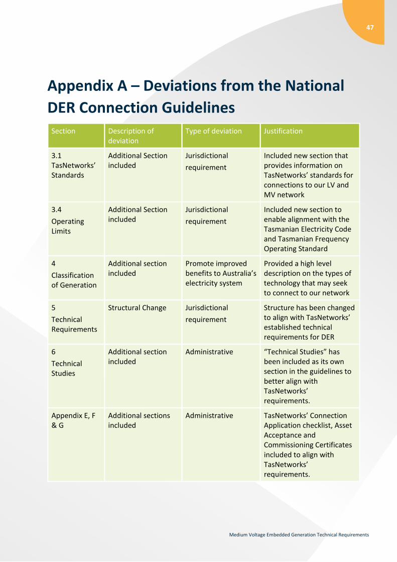
47
Medium Voltage Embedded Generation Technical Requirements
Appendix A – Deviations from the National
DER Connection Guidelines Section Description of
deviation Type of deviation Justification
3.1 TasNetworks’ Standards
Additional Section included
Jurisdictional
requirement
Included new section that provides information on TasNetworks’ standards for connections to our LV and MV network
3.4
Operating Limits
Additional Section included
Jurisdictional
requirement
Included new section to enable alignment with the Tasmanian Electricity Code and Tasmanian Frequency Operating Standard
4
Classification of Generation
Additional section included
Promote improved benefits to Australia’s electricity system
Provided a high level description on the types of technology that may seek to connect to our network
5
Technical Requirements
Structural Change Jurisdictional
requirement
Structure has been changed to align with TasNetworks’ established technical requirements for DER
6
Technical Studies
Additional section included
Administrative “Technical Studies” has been included as its own section in the guidelines to better align with TasNetworks’ requirements.
Appendix E, F & G
Additional sections included
Administrative TasNetworks’ Connection Application checklist, Asset Acceptance and Commissioning Certificates included to align with TasNetworks’ requirements.

48
Medium Voltage Embedded Generation Technical Requirements
Appendix B – Connection arrangement
requirements Sample single line diagrams are provided below.
TasNetworks’ preferred connection arrangement including TasNetworks’ network isolation device for
an MV EG System that cannot sustain a viable island is shown in Figure 1, and for an MV EG System
that requires anti-islanding inter-trip protection is shown in Figure 2. These diagrams are provided for
general reference only. The specific earthing, switchgear and protection arrangements will be
determined by the type of generating system to be connected. TasNetworks will require the
installation of its own network isolation device for all MV EG Systems.
DistributionNetwork Customer
Grid Isolation Device
TasNetworks Proponent
kWh
Revenue meter
Connection Point
MV EG System
TasNetworks Network Isolation Device
Transformer
VT
UFOFUVOV
Synch
OCEF
SEFNVD
Proponent Isolation Device
Figure 1: TasNetworks preferred connection arrangement for MV EG Systems with no viable island
DistributionNetwork Customer
Grid Isolation Device
TasNetworks Proponent
kWh
Revenue meter
Connection Point
MV EG System
TasNetworks Network Isolation Device
Transformer
VT
UFOFUVOV
Synch
OCEF
SEFNVD
R
TasNetworks Recloser
Proponent Isolation Device
TasNetworks NOCS
Upstream reclosers with
LLB
Figure 2: Example of TasNetworks communications based anti-islanding inter-trip protection scheme.
49
Medium Voltage Embedded Generation Technical Requirements
Appendix C – Model connection agreement TasNetworks’ Electricity Connection Contract - Standard Terms & Conditions can be found on our
website on our Contracts and policies page.

50
Medium Voltage Embedded Generation Technical Requirements
Appendix D – Static data and information 1) DER Installation at a NMI in aggregate:
a) NMI
b) Approved capacity
c) Installer identification
d) Connection agreement ‘Job number’ (provided by DNSP)
e) Number of phases available
f) Number of phases with DER installed
g) Central protection and control
h) Islandable installation
i) Protection and control modes
2) AC grid connection of a DER installation:
a) Number of AC connections
b) AC equipment type
c) Inverter/small generating unit manufacturer
d) Inverter series
e) Inverter model number
f) Inverter serial number
g) Commissioning date
h) Status of inverter (active, inactive or decommissioned)
i) Inverter device capacity (kVA)
j) What standards apply to the inverter
k) Sustained overvoltage (V)
l) Over-frequency (Hz)
m) Under-frequency (Hz)
n) Inverter – demand response enabled device interaction
o) Inverter power quality response mode – volt-watt (where enabled)
p) Inverter power quality response mode – volt-var (where enabled)
q) Inverter power quality response mode – reactive power mode (where enabled)

51
Medium Voltage Embedded Generation Technical Requirements
r) Inverter power quality response mode – fixed power factor mode (where enabled)
s) Inverter power quality response mode – power factor curve/power response mode(where enabled)
t) Inverter power quality response mode – power rate limit mode (where enabled)
u) Non-inverter generator – voltage/reactive power regulation
v) Non-inverter generator ramp rate (where enabled)
w) Non-inverter generator frequency response mode (where enabled)
x) Protection and control modes (i.e. ROCOF, vector shift, inter-trip, neutral voltage displacement)
3) DER energy sources:
a) Number of devices
b) Manufacturer
c) Model number
d) Status
e) Device type
f) Nominal rated capacity (kVA)
g) Nominal storage capacity (kVAh).

52
Medium Voltage Embedded Generation Technical Requirements
Appendix E – Generator Connection
Application Checklist The following information is expected to be provided to TasNetworks as part of the Connection
Application Package.
Items marked (*) may not be available at the time of submission, however TasNetworks expects to see
information within the Connection Application Package outlining how these requirements will be met,
e.g. relevant test plans etc.
TasNetworks recommends that Applicants submit complete and final design information in their
application package wherever possible, however preliminary design information may be accepted by
TasNetworks if necessary, at the Applicant’s risk. Any assessment or determination made by
TasNetworks on the basis of preliminary information is subject to change should the final design or as-
constructed plant materially change from the original submission. Any preliminary design information
must be updated with final design information no later than three months prior to commissioning.
Connections Study report demonstrating compliance against 5.3a of the Rules and these guidelines including supporting modelling information as discussed in Section 6.
Single-line diagram with the protection details and asset boundary shown;
General arrangement locating all the equipment on the site;
General arrangement for each new or altered substation showing all exits and the position of all electrical equipment;
Specific operational arrangements;
Information detailing the protection systems of the equipment;
Proposed methods of earthing cables and other equipment to comply with Tasmanian regulations;
Type test certificates for all new switchgear and transformers, including measurement transformers to be used for metering purposes in accordance with Chapter 7 of the Rules;
Earthing details;
Metering system design details for any metering equipment being provided by the Network User;
Procedure for the commissioning of the MV EG system;
Plant and earth grid test certificates from approved test authorities*;
Secondary injection and trip test certificate on all circuit breakers*;
Certification that all new equipment has been inspected before being connected to the supply*.
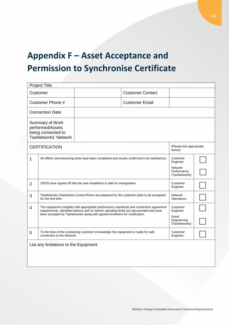
53
Medium Voltage Embedded Generation Technical Requirements
Appendix F – Asset Acceptance and
Permission to Synchronise Certificate
Project Title
Customer Customer Contact
Customer Phone # Customer Email
Connection Date
Summary of Work performed/Assets being connected to TasNetworks’ Network
CERTIFICATION (Please tick appropriate boxes)
1 All offline commissioning tests have been completed and results confirmed to be satisfactory. Customer Engineer
Network Performance (TasNetworks)
2 CBOS have signed off that the new installation is safe for energisation. Customer Engineer
3 TasNetworks Distribution Control Room are prepared for the customer plant to be energised for the first time.
Network Operations
4 The equipment complies with appropriate performance standards and connection agreement requirements. Identified defects and /or interim operating limits are documented and have been accepted by TasNetworks along with agreed timeframe for rectification.
Customer Engineer
Asset Engineering (TasNetworks)
5 To the best of the connecting customer’s knowledge the equipment is ready for safe connection to the Network.
Customer Engineer
List any limitations to the Equipment

54
Medium Voltage Embedded Generation Technical Requirements
List variances from Performance Standards or Connection Agreement
Customer Name Sign Date
Engineer
Project Manager
TasNetworks Name Sign Date
Network Performance
Asset Engineering
Network Operations
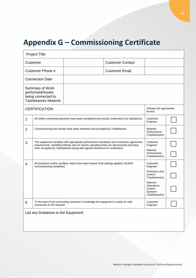
55
Medium Voltage Embedded Generation Technical Requirements
Appendix G – Commissioning Certificate
Project Title
Customer Customer Contact
Customer Phone # Customer Email
Connection Date
Summary of Work performed/Assets being connected to TasNetworks Network
CERTIFICATION (Please tick appropriate boxes)
1 All online commissioning tests have been completed and results confirmed to be satisfactory Customer Engineer
2 Commissioning test results have been reviewed and accepted by TasNetworks Network Performance (TasNetworks)
3 The equipment complies with appropriate performance standards and connection agreement requirements. Identified defects and /or interim operating limits are documented and have been accepted by TasNetworks along with agreed timeframe for rectification
Customer Engineer
Network Performance (TasNetworks)
4 All protection and/or auxiliary relays have been tested; final settings applied; SCADA commissioning completed
Customer Engineer
Protection and Control (TasNetworks)
Network Operations Control Systems (TasNetworks)
5 To the best of the connecting customer’s knowledge the equipment is ready for safe connection to the Network
Customer Engineer
List any limitations to the Equipment

56
Medium Voltage Embedded Generation Technical Requirements
List variances from Performance Standards or Connection Agreement
Customer Name Sign Date
Engineer
Project Manager
TasNetworks Name Sign Date
Network Performance
Protection and Control
Network Operations Control Systems
Network Operations