
MEDICAL TOURISM: AN ASSESSMENT ON TURKEY - Medeniyet
16
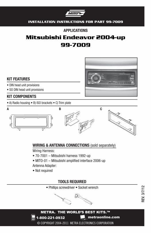
METRA. THE WORLD’S BEST KITS.™ © COPYRIGHT 2004-2011 METRA ELECTRONICS CORPORATION APPLICATIONS 1-800-221-0932 metraonline.com INSTALLATION INSTRUCTIONS FOR PART 99-7009 REV. 3/7/12 WIRING & ANTENNA CONNECTIONS (sold separately) Wiring Harness: • 70-7001 – Mitsubishi harness 1992-up • MITO-01 – Mitsubishi amplified interface 2006-up Antenna Adapter: • Not required • Phillips screwdriver • Socket wrench TOOLS REQUIRED Mitsubishi Endeavor 2004-up 99-7009 • A) Radio housing • B) ISO brackets • C) Trim plate KIT FEATURES KIT COMPONENTS B C A • DIN head unit provisions • SO DIN head unit provisions
Transcript of MEDICAL TOURISM: AN ASSESSMENT ON TURKEY - Medeniyet
METRA. THE WORLD’S BEST KITS.™
© COPYRIGHT 2004-2011 METRA ELECTRONICS CORPORATION
APPLICATIONS
1-800-221-0932 metraonline.com
INSTALLATION INSTRUCTIONS FOR PART 99-7009
REV.
3/7
/12
WIRING & ANTENNA CONNECTIONS (sold separately) Wiring Harness:• 70-7001 – Mitsubishi harness 1992-up• MITO-01 – Mitsubishi amplified interface 2006-upAntenna Adapter:• Not required
• Phillips screwdriver • Socket wrench
TOOLS REQUIRED
Mitsubishi Endeavor 2004-up99-7009
• A) Radio housing • B) ISO brackets • C) Trim plate
KIT FEATURES
KIT COMPONENTS
B CA
• DIN head unit provisions• SO DIN head unit provisions

Table of Contents
Dash Disassembly
– Mitsubishi Endeavor 2004-up ..........................................................................................3
Kit Assembly
– DIN head unit provision ....................................................................................................4
– ISO DIN head unit provision .............................................................................................5
KNOWLEDGE IS POWEREnhance your installation and fabrication skills by enrolling in the most recognized and respected mobile electronics school in our industry.Log onto www.installerinstitute.com or call 800-354-6782 for more information and take steps toward a better tomorrow.
Metra recommends MECP certified technicians
99-7009
CAUTION: Metra recommends disconnecting the negative battery terminal before beginning any installation. All accessories, switches, and especially air bag indicator lights must be plugged in before reconnecting the battery or cycling the ignition.
Note: Refer to the instructions included with the aftermarket radio.

1. Unsnap and remove entire panel surrounding radio and A/C controls.(Figure A)
2. Remove (1) 10 mm nut from the rear support on the top left of radio on cross bar behind dash. (Figure B)
3. Remove (3) Phillips screws to remove factory radio chassis. (Figure C)
4. Remove (4) Phillips screws from the pocket at the bottom of the radio and A/C panel and remove the pocket (this is where the 99-7009 will be mounted). (Figure D)
Continued to kit assembly
3
Mitsubishi Endeavor 2004-up
Dash Disassembly 99-7009
(Figure B)
(Figure D)
(Figure C)
(Figure A)

4
Kit Assembly 99-7009
Using the factory hardware, mount the 99-7009 in the location where the factory pocket resided.
1. Slide the DIN cage into the radio housing and secure by bending the metal locking tabs down. (Figure A)
2. Slide the after-market head unit into the cage and secure. Snap trim plate into the radio housing.
3. Locate the factory wiring harness in the dash. Metra recommends using the proper mating adapter from Metra or AXXESS. Re-connect the negative battery terminal and test the unit for proper operation.
4. Reassemble dash in reverse order of disassembly.
DIN head unit provision
(Figure A)

Kit Assembly 99-7009
5
Double DIN head unit provision
1. Mount the ISO brackets to the head unit with the screws supplied with the unit. (Figure A)
2. Slide the head unit into the radio opening until the side clips engage.
3. Snap the trim plate into the radio housing.
4. Locate the factory wiring harness in the dash. Metra recommends using the proper mating adapter from Metra or AXXESS. Re-connect the negative battery terminal and test the unit for proper operation.
5. Reassemble dash in reverse order of disassembly.
(Figure A)

Notes

Notes

METRA. THE WORLD’S BEST KITS.™
© COPYRIGHT 2004-2011 METRA ELECTRONICS CORPORATION 1-800-221-0932 metraonline.com
INSTALLATION INSTRUCTIONS FOR PART 99-7009
REV.
3/7
/12

METRA. THE WORLD’S BEST KITS.™
© COPYRIGHT 2004-2011 METRA ELECTRONICS CORPORATION
APLICACIONES
1-800-221-0932 metraonline.com
INSTRUCCIONES DE INSTALACIÓN PARA LA PIEZA 99-7009
REV.
3/7
/12• Destornillador Phillips • Herramienta toma de corriente
HERRAMIENTAS REQUERIDAS
Mitsubishi Endeavor 2004 y mas99-7009
• A) Alojamiento del radio • B) Soportes ISO • C) Placa de moldura
CARACTERÍSTICAS DEL KIT
COMPONENTES DEL KIT
B CA
• Provisión de unidad central DIN• Provisión de unidad central ISO DIN
CABLEADO Y CONEXIONES DE ANTENA (se venden por separado)Arnés de cableado:• 70-7001 – Arnés para Mitsubishi 1992 y más recientes• MITO-01 – Interfase Mitsubishi amplificada 2006 y más recientesAdaptador de antena:• No se requiere

Indice
Desmontaje del tablero
– Mitsubishi Endeavor 2004 y mas .....................................................................................3
Ensamble del kit
– Provisión de unidad central DIN .......................................................................................4
– Provisión de unidad central ISO DIN .................................................................................5
99-7009
PRECAUCIÓN: Metra recomienda desconectar el terminal negativo de la batería antes de comenzar cualquier instalación. Todos los accesorios, interruptores y, especialmente, las luces indicadoras de airbag deben estar enchufados antes de volver a conectar la batería o comenzar el ciclo de ignición.
Nota: Remítase a las instrucciones incluidas con el radio de posventa.
KNOWLEDGE IS POWEREnhance your installation and fabrication skills by enrolling in the most recognized and respected mobile electronics school in our industry.Log onto www.installerinstitute.com or call 800-354-6782 for more information and take steps toward a better tomorrow.
Metra recomienda técnicos con certificación del Programa de Certificación en Electrónica Móvil (Mobile Electronics Certification Program, MECP).
EL CONOCIMIENTO ES PODERMejore sus habilidades de instalación y fabricación inscribiéndose en la escuela de dispositivos electrónicos móviles más reconocida y respetada de nuestra industria. Regístrese en www.installerinstitute.com o llame al 800-354-6782 para obtener más información y avance hacia un futuro mejor.

1. Desenganche y quite todo el panel que rodea el radio y los controles del aire acondicionado. (Figura A)
2. Quite (1) tuerca de 10 mm del soporte trasero en la parte superior izquierda del radio en la barra transversal detrás del tablero. (Figura B)
3. Quite los (3) tornillos Phillips para quitar el chasís del radio de fábrica. (Figura C)
4. Quite los (4) tornillos Phillips del bolsillo en la parte inferior del radio y el panel del aire acondicionado y quite el bolsillo (aquí es donde se montará el 99-7009). (Figura D)
Continuará al ensamble del kit
3
Mitsubishi Endeavor 2004 y mas
Desmontaje del tablero 99-7009
(Figura B)
(Figura D)
(Figura C)
(Figura A)

4
Ensamble del kit 99-7009
Utilizando el hardware de fábrica, monte el 99-7009 en el lugar donde estaba el bolsillo de fábrica.
1. Deslice la reja DIN en la carcasa del radio y sujétela doblando hacia abajo las pestañas de metal. (Figura A)
2. Deslice la unidad central de mercado secundario en la reja y sujétela. Coloque a presión la placa de la moldura en la carcasa del radio.
3. Ubique el arnés del cableado de fábrica en el tablero. Metra recomienda usar el adaptador de acoplamiento adecuado de Metra o AXXESS. Vuelva a conectar el terminal negativo de la batería y pruebe la unidad para verificar que funcione correctamente.
4. Vuelva a montar el tablero en forma inversa al desmontaje.
Provisión de unidad central DIN
(Figura A)

Ensamble del kit 99-7009
5
Provisión de unidad central ISO DIN
1. Monte los soportes ISO en la unidad central con los tornillos incluidos con la unidad. (Figura A)
2. Deslice la unidad central en la apertura del radio hasta que los ganchos laterales se enganchen.
3. Coloque a presión la placa de la moldura en la carcasa del radio.
4. Ubique el arnés del cableado de fábrica en el tablero. Metra recomienda usar el adaptador de acoplamiento adecuado de Metra o AXXESS. Vuelva a conectar el terminal negativo de la batería y pruebe la unidad para verificar que funcione correctamente.
5. Vuelva a montar el tablero en forma inversa al desmontaje.
(Figura A)

Notas

Notas

METRA. THE WORLD’S BEST KITS.™
© COPYRIGHT 2004-2011 METRA ELECTRONICS CORPORATION 1-800-221-0932 metraonline.com
INSTRUCCIONES DE INSTALACIÓN PARA LA PIEZA 99-7009
REV.
3/7
/12


![DAVID D. LAITIN - Political Science · Civilization Studies of Istanbul Medeniyet University, Turkey, 2014 [With James Fearon] ^Muslims in France: identifying a discriminatory equilibrium](https://static.fdocuments.us/doc/165x107/5e45372b43cad530a4636a4c/david-d-laitin-political-science-civilization-studies-of-istanbul-medeniyet-university.jpg)