
Mediator Johnson N1
15
1 Mediator-Johnson N1 Device Configuration Manual Supplement to the Mediator User’s Guide Envenergy, Inc. Richards-Zeta Building Intelligence, Inc. 6307 Carpinteria Avenue, Suite B 6326 Lindmar Drive Carpinteria, CA 93013 Goleta, CA 93117 (805) 745-5200 (805) 692-5560 FAX (805) 745-5800 FAX (805) 692-5513 www.envenergy.com www.richards-zeta.com
Transcript of Mediator Johnson N1
1
Mediator-Johnson N1 Device
Configuration Manual
Supplement to the Mediator User’s Guide
Envenergy, Inc. Richards-Zeta Building Intelligence, Inc. 6307 Carpinteria Avenue, Suite B 6326 Lindmar Drive Carpinteria, CA 93013 Goleta, CA 93117 (805) 745-5200 (805) 692-5560 FAX (805) 745-5800 FAX (805) 692-5513 www.envenergy.com www.richards-zeta.com

Mediator-Johnson N1 Device
Version 1.3
2
2003 Richards-Zeta Building Intelligence, Inc. All rights reserved. 2003 Envenergy, Inc. All rights reserved.
Mediator is a trademark of Envenergy, Inc.
Johnson Controls is a registered trademark of Johnson Controls, Inc.
Mediator-Johnson N1 Device
Version 1.3
3
Table of Contents
Section Page
Table of Contents............................................................................................................................................................................ iii
List of Figures ................................................................................................................................................................................. iii
List of Tables ................................................................................................................................................................................... iii
1. Overview............................................................................................................................................................................1
1.1 Audience.............................................................................................................................................................................1
1.2 References..........................................................................................................................................................................1
2. Hardware Connection.......................................................................................................................................................1
2.1 Typical System Diagrams ...............................................................................................................................................1
2.2 Johnson System Configuration Information ................................................................................................................5
3. Mediator Configuration ...................................................................................................................................................6
3.1 Overview of the Mediator Configuration Tool............................................................................................................6
3.2 Configuring Johnson N1 Devices ..................................................................................................................................6
List of Figures
Page
Figure 1 Single Johnson NCM Architecture ........................................................................................................................2
Figure 2 Multiple Johnson NCM Architecture (Separate Ethernet Networks)..............................................................3
Figure 3 Multiple Johnson NCM Architecture (Unified Ethernet Network)..................................................................4
List of Tables
Page
Table 1 Single Johnson NCM Architecture ........................................................................................................................5
Mediator/Johnson N1 Device Configuration Manual
Envenergy Document No.XXX Page 1 June 2003
1. Overview
This document describes how to connect a Mediator to a Johnson NCM 350, NCM 300 or NCM 200 device and configure the Mediator to access the information from the Johnson N1 primary network. The Mediator’s implementation of the Johnson N1 protocol driver allows the Mediator to transfer data to and from a Johnson NCM network over a single RS-232 connection.
The Johnson Controls NCM (Network Control Module) 350 is a Supervisory Interface (SI) device that provides control and communications for controllers connected to a secondary (N2) network. The NCM 350 can be connected to Ethernet IP or ARCNET N1 primary networks. The NCM300 can only be used with ARCNET N1 primary networks.
1.1 Audience
This document is intended for installers and system administrators of Envenergy Mediator systems. It assumes that you are experienced and knowledgeable in the setup and configuration of networks, especially TCP/IP networking in an enterprise Information Technology (IT) environment. You should be familiar with the Windows Operating System. Familiarity with the Linux Operating System is helpful but not required.
1.2 References
Mediator 1.3 Installation Manual, Envenergy Publication No. 801-0002-002
Mediator User’s Manual Version 1.3 , Envenergy Publication No. 801-0003-002
Mediator 2500 Product Description
Mediator 1500 Product Description

Mediator/Johnson N1 Device Configuration Manual
Envenergy Document No.XXX Page 2 June 2003
2. Hardware Connection
The Mediator is physically connected to the Johnson NCM by means of an RS-232 null modem cable. The cable can be connected to either of the Mediator’s DB-9 RS-232 ports (labeled Com 1 and Com 2) and one of the Johnson NCM’s RS-232 ports.
Note: The NCM’s Port 3 is preferred; Port 5 and 6 are also acceptable.
The RS-232 port on the Johnson NCM must be designated an Unconfigured Work Station port through the Johnson Operator Work Station (OWS) software.
2.1 Typical System Diagrams
The Mediator is capable of operating in many different system architectures based on the Johnson N1 system. The diagrams in this section represent several typical installation architectures.
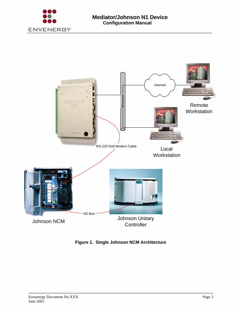
Figure 1 shows the architecture of a system in a building that has only one Johnson NCM. The Mediator is connected to the NCM through an RS-232 null modem connection and to an Ethernet network through its built-in Ethernet port.
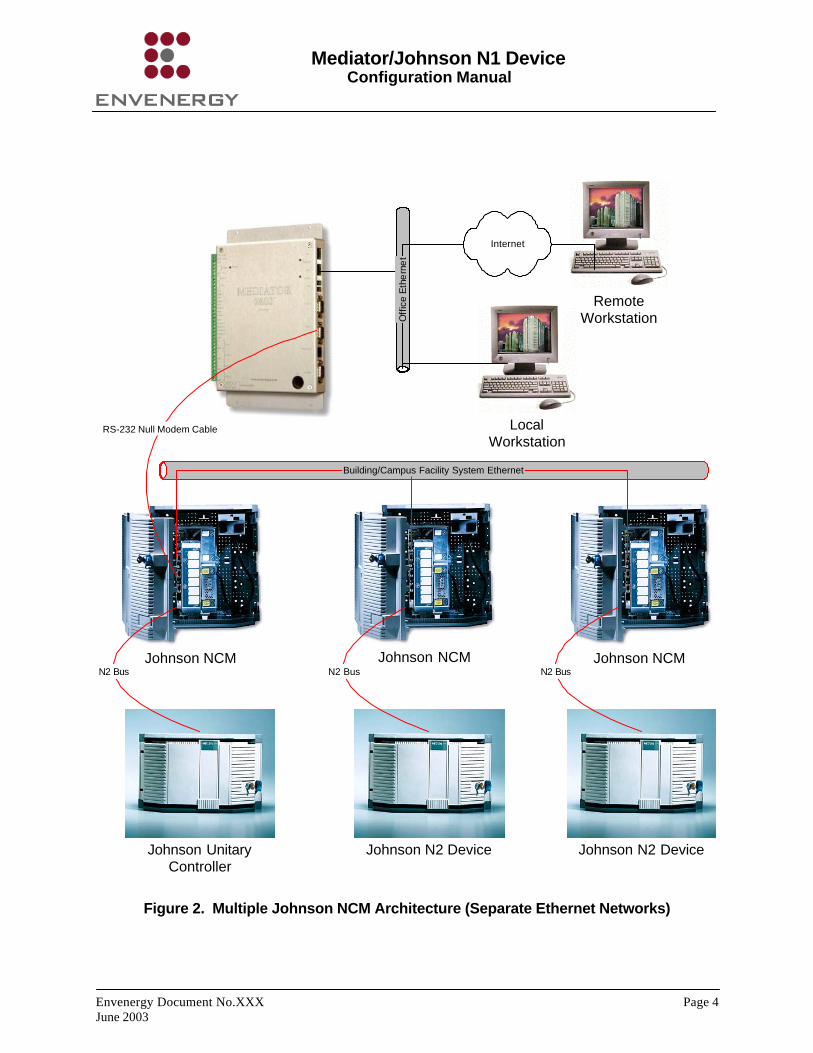
Figure 2 shows the architecture of a system in a building or campus with multiple Johnson NCMs. The NCM devices are connected to an Ethernet network that is reserved for the building system. The Mediator connects directly to one NCM in the system via RS-232. It can exchange information with any of the other NCMs through the Ethernet connection.. The Mediator is also connected to a separate Ethernet network that allows communication with the office LAN (and possibly with the Internet).
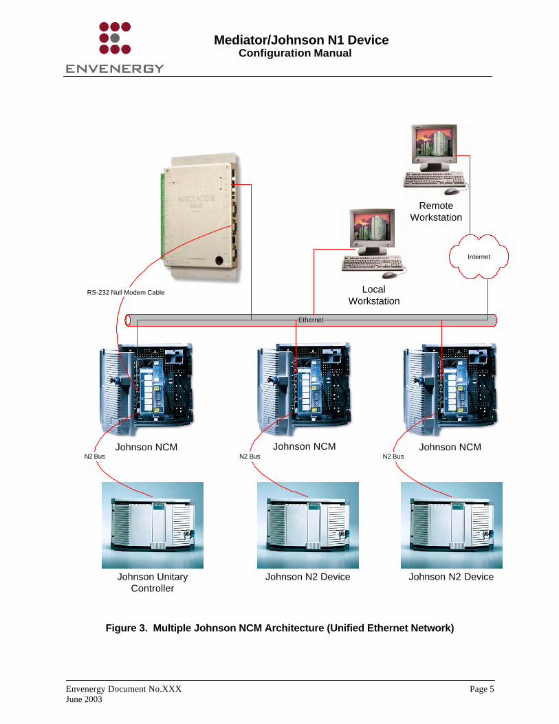
Figure 3 shows the architecture of a system similar to the one in Figure 2, except that there is only one Ethernet network in the building, which supports communication for both the office information and the building system.
Mediator/Johnson N1 Device Configuration Manual
Envenergy Document No.XXX Page 3 June 2003
LocalWorkstation
Johnson NCM
Eth
ern
et
RS-232 Null Modem Cable
Johnson UnitaryController
N2 Bus
Internet
RemoteWorkstation
Figure 1. Single Johnson NCM Architecture
Mediator/Johnson N1 Device Configuration Manual
Envenergy Document No.XXX Page 4 June 2003
LocalWorkstation
Johnson NCM
Off
ice
Eth
ern
et
Johnson UnitaryController
N2 Bus
Internet
RemoteWorkstation
Johnson NCM Johnson NCM
Johnson N2 Device
N2 Bus
Johnson N2 Device
N2 Bus
Building/Campus Facility System Ethernet
RS-232 Null Modem Cable
Figure 2. Multiple Johnson NCM Architecture (Separate Ethernet Networks)
Mediator/Johnson N1 Device Configuration Manual
Envenergy Document No.XXX Page 5 June 2003
LocalWorkstation
Johnson NCM
Johnson UnitaryController
N2 Bus
Internet
RemoteWorkstation
Johnson NCM Johnson NCM
Johnson N2 Device
N2 Bus
Johnson N2 Device
N2 Bus
Ethernet
RS-232 Null Modem Cable
Figure 3. Multiple Johnson NCM Architecture (Unified Ethernet Network)
Mediator/Johnson N1 Device Configuration Manual
Envenergy Document No.XXX Page 6 June 2003
2.2 Johnson System Configuration Information
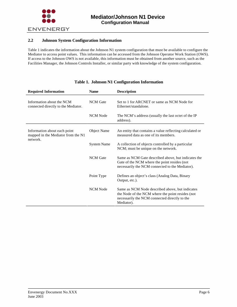
Table 1 indicates the information about the Johnson N1 system configuration that must be available to configure the Mediator to access point values. This information can be accessed from the Johnson Operator Work Station (OWS). If access to the Johnson OWS is not available, this information must be obtained from another source, such as the Facilities Manager, the Johnson Controls Installer, or similar party with knowledge of the system configuration.
Table 1. Johnson N1 Configuration Information
Required Information Name Description
NCM Gate Set to 1 for ARCNET or same as NCM Node for Ethernet/standalone.
Information about the NCM connected directly to the Mediator.
NCM Node The NCM’s address (usually the last octet of the IP address).
Object Name An entity that contains a value reflecting calculated or measured data as one of its members.
System Name A collection of objects controlled by a particular NCM; must be unique on the network.
NCM Gate Same as NCM Gate described above, but indicates the Gate of the NCM where the point resides (not necessarily the NCM connected to the Mediator).
Point Type Defines an object’s class (Analog Data, Binary Output, etc.).
Information about each point mapped in the Mediator from the N1 network.
NCM Node Same as NCM Node described above, but indicates the Node of the NCM where the point resides (not necessarily the NCM connected directly to the Mediator).

Mediator/Johnson N1 Device Configuration Manual
Envenergy Document No.XXX Page 7 June 2003
3. Mediator Configuration
The following procedure describes how to use the Mediator Configuration Tool to configure the Mediator to communicate with the Johnson N1 network.
3.1 Overview of the Mediator Configuration Tool
The Mediator Configuration Tool is an interactive, menu-driven software application that allows you to configure a Mediator host, including setting the network connection parameters and specifying the operating parameters of data points, devices, and systems connected to the Mediator. The Configuration Tool software is distributed on CD-ROM and is installed on a PC that is networked with the Mediator.
You use the Configuration Tool to set the Mediator’s network parameters and to configure the objects within the system that handles information. In Mediator terminology, these objects are referred to as nodes. A node is a named entity that exchanges information with other nodes (for example, a port, a Modbus line handler, a point, etc.), or supports the exchange of information (for example, the HTTP service). Nodes are used to represent the relationships between objects in the system. Like the Mediator Framework software, the Configuration Tool groups nodes into three main categories:
• Interfaces: Interface nodes include the sensors and devices connected to the Mediator.
• Aliases: Alias nodes are used to assign alternative names to other nodes. Aliases allow users to assign a meaningful name to any node in the system. For example, you could assign the alias Computer Room Temperature to a specific temperature sensor in the system.
• Services: Service nodes perform an action (for example, the Logger, network services such as the HTTP Server, etc.).
When you select a Mediator host to configure, the Configuration Tool displays a set of default nodes appropriate to the selected host, and provides the configuration options appropriate to each node.
When you finish specifying the host’s configuration parameters, the Configuration Tool produces a Configuration File, an XML file that describes the system configuration. At system startup, the Mediator Framework parses the Configuration File and uses the information it contains to dynamically assemble a running system on the Mediator.
3.2 Configuring Johnson N1 Devices
1. To start the Configuration Tool, double click the Mediator Configuration Tool icon.
Or click the Start button and access the Mediator Configuration Tool start command from the Programs menu.
Mediator/Johnson N1 Device Configuration Manual
Envenergy Document No.XXX Page 8 June 2003
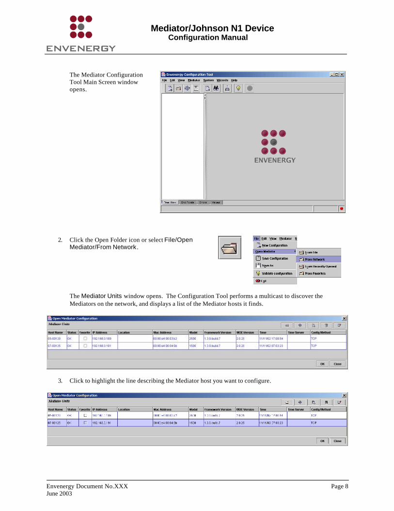
The Mediator Configuration Tool Main Screen window opens.
2. Click the Open Folder icon or select File/Open Mediator/From Network .
The Mediator Units window opens. The Configuration Tool performs a multicast to discover the Mediators on the network, and displays a list of the Mediator hosts it finds.
3. Click to highlight the line describing the Mediator host you want to configure.
Mediator/Johnson N1 Device Configuration Manual
Envenergy Document No.XXX Page 9 June 2003
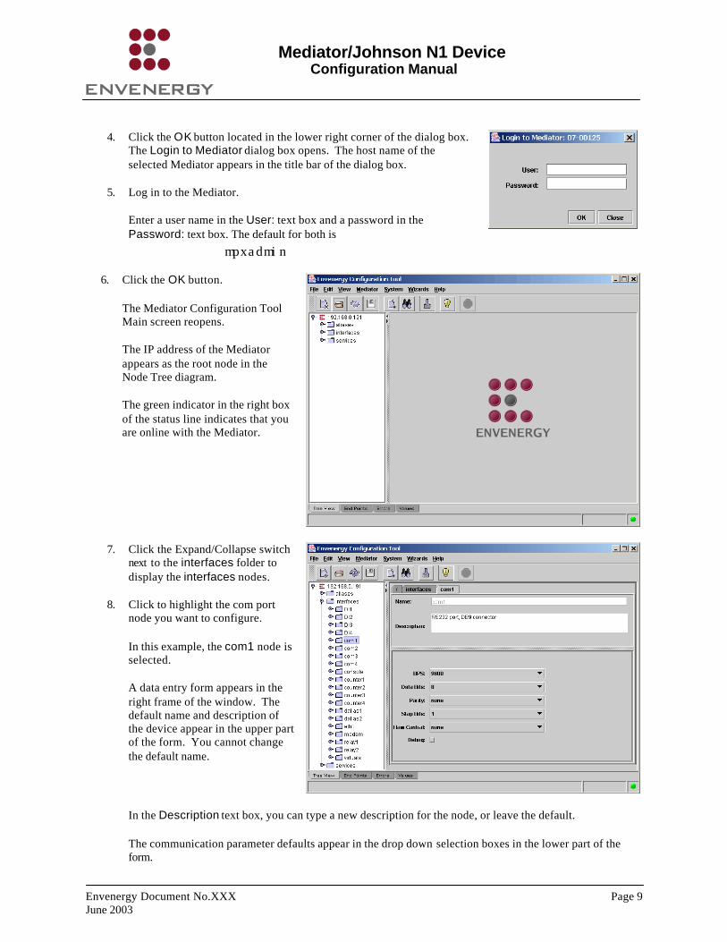
4. Click the OK button located in the lower right corner of the dialog box.
The Login to Mediator dialog box opens. The host name of the selected Mediator appears in the title bar of the dialog box.
5. Log in to the Mediator.
Enter a user name in the User: text box and a password in the Password: text box. The default for both is
mpxadmin
6. Click the OK button.
The Mediator Configuration Tool Main screen reopens.
The IP address of the Mediator appears as the root node in the Node Tree diagram.
The green indicator in the right box of the status line indicates that you are online with the Mediator.
7. Click the Expand/Collapse switch next to the interfaces folder to display the interfaces nodes.
8. Click to highlight the com port node you want to configure.
In this example, the com1 node is selected.
A data entry form appears in the right frame of the window. The default name and description of the device appear in the upper part of the form. You cannot change the default name.
In the Description text box, you can type a new description for the node, or leave the default.
The communication parameter defaults appear in the drop down selection boxes in the lower part of the form.
Mediator/Johnson N1 Device Configuration Manual
Envenergy Document No.XXX Page 10 June 2003
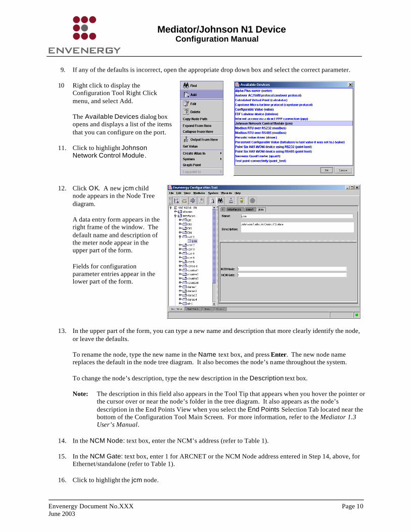
9. If any of the defaults is incorrect, open the appropriate drop down box and select the correct parameter.
10 Right click to display the Configuration Tool Right Click menu, and select Add.
The Available Devices dialog box opens and displays a list of the items that you can configure on the port.
11. Click to highlight Johnson Network Control Module .
12. Click OK. A new jcm child node appears in the Node Tree diagram.
A data entry form appears in the right frame of the window. The default name and description of the meter node appear in the upper part of the form.
Fields for configuration parameter entries appear in the lower part of the form.
13. In the upper part of the form, you can type a new name and description that more clearly identify the node, or leave the defaults.
To rename the node, type the new name in the Name text box, and press Enter. The new node name replaces the default in the node tree diagram. It also becomes the node’s name throughout the system.
To change the node’s description, type the new description in the Description text box.
Note: The description in this field also appears in the Tool Tip that appears when you hover the pointer or the cursor over or near the node’s folder in the tree diagram. It also appears as the node’s description in the End Points View when you select the End Points Selection Tab located near the bottom of the Configuration Tool Main Screen. For more information, refer to the Mediator 1.3 User’s Manual.
14. In the NCM Node: text box, enter the NCM’s address (refer to Table 1).
15. In the NCM Gate: text box, enter 1 for ARCNET or the NCM Node address entered in Step 14, above, for Ethernet/standalone (refer to Table 1).
16. Click to highlight the jcm node.

Mediator/Johnson N1 Device Configuration Manual
Envenergy Document No.XXX Page 11 June 2003
17. Right click to display the Node Tree Right Click menu,
and select Add. The Available Devices dialog box opens and displays a list of supported child nodes.
18. Click to highlight Point on Johnson NCM .
19. Click OK. A new ncm_point child node appears in the Node Tree diagram.
A data entry form appears in the right frame of the window. The default name and description of the ncm_point node appear in the upper part of the form.
Fields for required entries (labeled in red) and optional entries appear in the lower part of the form.
20. In the upper part of the form, you can type a new name and description that more clearly identify the node, or leave the defaults.
To rename the node, type the new name n the Name text box, and press Enter. The new node name replaces the default in the node tree diagram. It also becomes the node’s name throughout the system.
Note: The objects added to the configuration must match those that exist in the programming of the Johnson device.
To change the node’s description, type the new description in the Description text box.
Note: The description in this field also appears in the Tool Tip that appears when you hover the pointer or the cursor over or near the node’s folder in the tree diagram. It als o appears as the node’s description in the End Points View when you select the End Points Selection Tab located near the bottom of the Configuration Tool Main Screen. For more information, refer to the Mediator 1.3 User’s Manual.
21. Open the Type: drop down selection box.
The drop down box contains a list of the data points supported by the Johnson NCM device.
Select a data point type from the list (refer to Table 1).
22. In the required System Name: text box, enter the System Name (refer to Table 1).

Mediator/Johnson N1 Device Configuration Manual
Envenergy Document No.XXX Page 12 June 2003
23. In the required Object Name: text box, enter the Object Name (refer to Table 1).
24. In the NCM Node: text box, enter the NCM Node number (refer to Table 1).
The NCM Node number is a unique number assigned to each NCM. The Node number is usually the last octet of the IP address. For example, if the NCM has an IP address of 10.0.1.1 the NCM Node is 1; if the NCM IP address is 10.0.1.46 the NCM Node is 46.
25. In the NCM Gate: text box, enter the NCM Gate number (refer to Table 1).
If the NCM is on an Ethernet network, the NCM Gate number will be the same as the NCM Node number. If the NCM is on an ARCNET network, the NCM Gate Number is 1.
26. Save the configuration (refer to the Mediator 1.3 User’s Manual).


![V P V U R gq ^ ý u;Vóÿ d u;S:Wßÿ ^ WS S:Wß0]0nÿ ) N …...N N N N N N N N N N N N N N N N N N N N N N N N N N N N N N N N N P N1 N1 N1 N1 N1 N1 N1 N1 N1 N1 N1 N1 P P P N1 N1](https://static.fdocuments.us/doc/165x107/5fbf575d848b0b7e9575f4b2/v-p-v-u-r-gq-uv-d-usw-ws-sw00n-n-n-n-n-n-n-n-n-n.jpg)