
Medial migration of intramedullary intertrochanteric fracture
93
Medial Migration of Intramedullary Intertrochanteric Fracture Fixation Devices A Thesis Submitted to the Faculty of Drexel University by George Mikhail in partial fulfillment of the requirements for the degree of Master of Science in Biomedical Engineering May 2009
Transcript of Medial migration of intramedullary intertrochanteric fracture

Medial Migration of Intramedullary Intertrochanteric Fracture Fixation Devices
A Thesis
Submitted to the Faculty
of
Drexel University
by
George Mikhail
in partial fulfillment of the
requirements for the degree
of
Master of Science in Biomedical Engineering
May 2009

© Copyright 2008 George Mikhail. All Rights Reserved

Acknowledgements I would like to thank Glen Pierson, my supervisor at Synthes for his continued support of
this project and numerous brainstorming sessions especially when the project seemed to
hit a dead end. I also want to thank Darrin Chastain, Cal Stewart, and Chuck Beale for
their work with us in the mechanical test lab, and for patiently allowing us to spend time
on their machines just experimenting with various test set-ups that for a long time seemed
like they would never work.

iii Table of Contents
List of Tables ..................................................................................................................... iv List of Figures ..................................................................................................................... v Abstract .............................................................................................................................. vi Purpose and Summary of Specific Aims ......................................................................... viii Chapter 1: Introduction ....................................................................................................... 1 1.1 Hip Fracture Introduction ............................................................................................. 1 1.2 Intertrochanteric Plate Fixation Devices....................................................................... 2 1.3 Intramedullary Intertrochanteric Fixation Devices....................................................... 5 1.4 Hip Fixation and Superior Cut-Out .............................................................................. 9 1.5 Z-Effect ....................................................................................................................... 14 1.6 Medial Migration ........................................................................................................ 16 Chapter 2: Specific Aim #1 – Mechanical Test Construct ............................................... 18 2.1 Hypothesis................................................................................................................... 19 2.2 Test Objective ............................................................................................................. 22 2.3 Phase I......................................................................................................................... 22
2.3.1 Materials and Methods..................................................................................... 22 2.3.2 Results and Conclusions of Phase I ................................................................. 26
2.4 Phase II........................................................................................................................ 29 2.4.1 Materials and Methods..................................................................................... 29 2.4.2 Results and Conclusion of Phase II ................................................................. 31
2.5 Discussion ................................................................................................................... 32 Chapter 3: Specific Aim #2 – Construct Validation in Foam Model ............................... 35 3.1 Hypothesis................................................................................................................... 35 3.2 Test Objective ............................................................................................................. 36 3.3 Phase I......................................................................................................................... 36
3.3.1 Materials and Methods..................................................................................... 36 3.3.2 Results and Conclusion of Phase I................................................................... 39
3.4 Phase II........................................................................................................................ 40 3.4.1 Materials and Methods..................................................................................... 40 3.4.2 Results and Conclusion of Phase II ................................................................. 43
Chapter 4: Specific Aim #3 – Testing Other Implant Designs For Medial Migration ..... 45 4.1 Construct Setup........................................................................................................... 48
4.1.1 Nail Construct .................................................................................................. 48 4.1.2 Femoral Head Construct .................................................................................. 50 4.1.3 LVDT Attachment ........................................................................................... 53 4.1.4 List of Implants ................................................................................................ 54
4.2 Procedure .................................................................................................................... 55 4.3 Results and Discussion ............................................................................................... 56 Chapter 5: Final Conclusion/Future Research .................................................................. 61 List of References ............................................................................................................. 66 Appendix A: Fixture Drawings......................................................................................... 69

iv List of Tables
Table 1. Mechanical Properties of Cellular Rigid Closed Cell Polyurethane Foam ........ 37 Table 2 LVDT Calibration Data ....................................................................................... 56 Table 3. Summary of Medial Migration Results for Various Implants Tested ................ 57 Table 4. Detailed Results of Medial Migration Testing Per Implant................................ 60

v
List of Figures Figure 1. AO Classification of Intertrochanteric Fractures. .............................................. 1 Figure 2. 130º Angle Blade Plate........................................................................................ 3 Figure 3. Dynamic Hip Screw ............................................................................................ 3 Figure 4. IM vs Plate Lever Arm. ....................................................................................... 6 Figure 5. IM Buttress .......................................................................................................... 6 Figure 6. Plate Reverse Oblique Fracture ........................................................................... 7 Figure 7. IM Nail Reverse Oblique Fracture ...................................................................... 7 Figure 8. Fracture at Tip of Short Nails.............................................................................. 9 Figure 9. Screw Slot to Reduce Fracture at Tip of Short Nails .......................................... 9 Figure 10. Calculating TAD ............................................................................................. 10 Figure 11. Cut-Out Based on Insertion Region ................................................................ 10 Figure 12. Pugh Sliding Blade .......................................................................................... 12 Figure 13. Synthes TFN Helical Blade ............................................................................. 12 Figure 14. Bone Removal Comparison............................................................................. 12 Figure 15. Cut-Out Rate Comparison, Helical Blade vs Lag Screw ................................ 13 Figure 16. Rotational Stability, Helical Blade vs. Lag Screw .......................................... 14 Figure 17. Z-effect ............................................................................................................ 15 Figure 18. Reverse Z-effect .............................................................................................. 15 Figure 19. Medial Migration of Lag Screw Device. ......................................................... 17 Figure 20. Hypothesis of Causes of Medial Migration..................................................... 20 Figure 21. Phase I Test Construct ..................................................................................... 25 Figure 22. Thrust Bearing Adaptor................................................................................... 26 Figure 23. Thrust Bearing Action ..................................................................................... 26 Figure 24. Wedge Effect ................................................................................................... 28 Figure 25. Phase II Test Construct.................................................................................... 30 Figure 26. Photo of Phase II Construct on MTS Machine................................................ 31 Figure 27. Toggling Needed for Short Cephalomedullary Nails...................................... 33 Figure 28. Foam Head Construct. ..................................................................................... 38 Figure 29. Valgus Rotation of Foam Construct ................................................................ 40 Figure 30. Fixture With New Reaction Angle .................................................................. 42 Figure 31. Stryker Ineffective Attempt to Prevent Medial Migration .............................. 46 Figure 32. Limiting Overall Migration ............................................................................. 46 Figure 33. Series of Images Showing the Initial Implantation, Subsequent Collapse, and Medial Migration .............................................................................................................. 48 Figure 34. Nail Fixture Built to Accommodate Various Cephalomedullary Implants ..... 50 Figure 35. Head construct ................................................................................................. 52 Figure 36. Flats on IMHS Lag Screw ............................................................................... 53 Figure 37. Final Construct Used for Testing the Various Implants.................................. 54 Figure 38. Friction Lock to Prevent Migration................................................................. 64

vi Abstract
Intramedullary Intertrochanteric Nail Fixation Devices and Medial Migration of Their Femoral Neck Implants
George Mikhail Glen Pierson, Synthes USA, Supervisor
Intertrochanteric fractures have been fixed for decades with side plates and sliding
hip screws, and more recently, with intramedullary devices and sliding lag screws. The
most common failure mode of all such implants is superior cutout of the implant due to
varus collapse of the femoral head and neck over the implant. The major cause of this
type of failure mode is believed to be osteopenic bone.
Another rarely reported failure mode, is the medial migration of the femoral neck
implant along its axis through the femoral head into the acetabulum. In follow-up x-rays,
the femoral neck implant is seen to migrate through the intramedullary nail, and out of
the femoral head. In this failure mode, the femoral head and neck do not collapse or may
have already collapsed as far as possible, but instead the implant migrates medially on its
own. The failure is very rare with few reported incidents over many years of use and
hundreds of thousands of fractures. Due to its rarity, this mode has not been sufficiently
documented or studied, nor is the cause well understood. It is postulated that the failure
could be due to a specific combination of the physiologic properties of the bone, fracture
pattern, and implant design.
The purpose of this research is to create a biomechanical test model that would
reliably reproduce the medial migration phenomenon in a controlled lab setting. Once a
robust model is achieved, various implant designs can be tested to determine if they
effectively prevent this phenomenon from occurring. It is not our purpose to analyze or

vii predict the parameters that might induce medial migration. The event is rarely observed
in the clinical setting. The parameters that may be contributing to this phenomenon are
numerous, difficult to clinically assess, and there are not enough clinical cases to study.
However if an implant is to be designed that would eliminate the capability for medial
migration it must be tested. This project sets out to create a robust test model that can
reliably be used to test designs claiming to fix the problem.
During the course of the study we came across situations that may provide insight
into other failure modes. Our test construct design iterations sometimes displayed other
failures that were not studied before, including the femoral head collapsing along the axis
of the blade, but the blade itself not sliding as it is designed. We also discovered that
two-screw devices are more prone to the “Z-effect,” which is another form of medial
migration. This correlated to the fact that the “Z-effect” was commonly reported in the
literature with two-screw devices while medial migration was almost never reported due
to its very low occurrence rate.
The research did successfully create a biomechanical model that recreated the
phenomenon of medial migration and can be used to test potential fixes to prevent medial
migration. Without a biomechanical test model, all fixes are only theoretical and cannot
be proven until thousands of cases have been performed because of the rarity of the
failure. We hope that this work can be used to further improve implant designs reducing
the number of revision surgeries needed after initial hip fixation.

viii
Purpose and Summary of Specific Aims The purpose of this research is to create a biomechanical test model that would
reliably reproduce the medial migration phenomenon in a controlled lab setting. Once a
robust model is achieved, current implant designs can be tested to determine if they
effectively prevent this phenomenon from occurring. Additionally, new designs
attempting to prevent this failure mode can be tested to prove their efficacy.
Specific Aim 1 The first goal of this project is to develop a mechanical test model to simulate and
recreate the phenomenon of medial migration of the intertrochanteric nail fixation device.
This model will be entirely composed of metal and plastic components to allow full
control of all variables of the test.
Specific Aim 2 The second goal is to validate the model as biomechanically accurate, by placing
the actual neck implants into foam blocks that simulate the cancellous bone of the
femoral head instead of the plastic. For the construct to be considered valid, traditional
varus collapse of the femoral head model should be observed.
Specific Aim 3 The third goal of this project is to evaluate various implants from different
manufacturers on our validated biomechanical test model to determine if any implant
designs inherently prevent this phenomenon from occurring.
If all these aims are achieved, this test model can be used later to evaluate implant
concepts that are specifically designed to prevent this motion, since it seems that this
failure is not only due to physiologic parameters, but a combination of physiologic
conditions and mechanical design of the implant.


1
Chapter 1: Introduction 1.1 Hip Fracture Introduction
Hip fractures are a growing trend especially among the baby boomer generation
occurring at a rate of 250,000 per year and are expected to grow to 500,000 per year by
the year 2040. Approximately half of those are intertrochanteric fractures, often
occurring in the elderly after a simple fall [1]. These proximal femur fractures can be
identified under the classification system setup by the AO/OTA, which differentiate the
different fracture types for easy identification. In the AO/OTA classification system, the
first number designates the bone involved. For example, the humerus is designated by
the number 1, the forearm is designated by the number 2, the femur is designated a 3, and
the tibia is designated a 4. The second number typically designates which third of the
bone is involved. A “1” indicates a proximal third fracture, a “2” indicates a shaft
fracture, and a “3” indicates a distal third fracture. Therefore a proximal femur fracture is
described as a “31” fracture. Additionally, in the proximal femur, a further breakdown of
the fracture is designated. A 31-A fracture is an extracapsular fracture involving the
trochanteric region, a 31-B fracture is extracapsular, involving the femoral neck, and a
31-C fracture is intracapsular involving the femoral head. Each of those are further
broken down based on stability or severity of the fracture. The implants discussed in this
project are used with 31-A(1-3) type fractures as shown in the picture below.
Figure 1. AO Classification of Intertrochanteric Fractures.

2 1.2 Intertrochanteric Plate Fixation Devices
There has been an evolution of fixation methods for the intertrochanteric or
pertrochanteric fractures, classified as 31-A fractures. Early fixation methods often
included an angle blade plate device like the Jewett Nail [Figure 2] which consisted of a
side plate that was screwed to the lateral side of the femur and a blade that was
hammered into the femoral head. The side plate and blade were all one piece, making the
procedure technically challenging. These early blades were not cannulated, so the
surgeon had to determine the appropriate neck angle and anteversion of the head and then
chisel a path for the blade matching the angle of the implant. If the fracture was not
properly reduced before chiseling the path, or if the neck angle or anteversion of the
chiseled path was not correct, the fracture could often be malreduced. Valgus
malreductions create an angle between the femoral shaft and the axis of the femoral neck
that is larger than it originally was. This type of malreduction, aside from not matching
the anatomic geometry, often leaves a gap between the two main bony fragments around
the level of the lesser trochanter. A gap in this condition causes three problems. First, if
the gap is too large, the bone may not heal at all. Second, lack of bony support around
the level of the lesser trochanter puts more stress on the implant. The implants are
designed to share the load with the bone until the bone starts healing, but with no bony
contact, the implant carries the entire load for a longer period of time, and might
therefore fail. Third, the loads on the femur are directed toward the lesser trochanter and
without bony contact between the medial and lateral fragments, the bone in the femoral
head takes all of the load during weight bearing. The majority of the patients who
present with hip fractures are elderly patients with osteopoenic bone. The femoral head

3 might not be able to support the implant and might fall into varus, collapsing around the
implant, causing the blade to stick out of the femoral head. Varus collapse in the
proximal femur occurs when the angle between the femoral neck and the femoral shaft
becomes smaller than it originally was, either due to a malreduction or due to implant
failure, or cutout of the implant through the femoral head because of poor bone quality.
Figure 2. 130º Angle Blade Plate Figure 3. Dynamic Hip Screw
The next major evolution in hip fixation was commonly called either the Dynamic
Hip Screw (DHS) or Compression Hip Screw (CHS). This implant was composed of two
pieces, a lag screw that went up into the femoral head, and a side plate with a barrel that
engaged the lag screw and then screwed into the shaft of the femur. This made the
technique much less technically demanding for at least two reasons. First, the lag screw
was cannulated. Therefore a small guide wire, usually around 2.5mm in diameter, could
be placed into the femoral head through an alignment jig, determining the placement of

4 the lag screw. If the guide wire is placed incorrectly, it can be easily corrected without
removing much bone before the implant has been inserted. Once the guide wire is
satisfactorily placed, a cannulated drill bit is placed over the guide wire to drill through
the femoral head. A tap can then follow the drill bit if desired and then the lag screw can
be inserted. Finally, the barrel of the side plate is placed around the shaft of the lag screw
and the plate is brought down to the bone and screwed to the femoral shaft. The lag
screw can freely slide through the barrel of the side plate, permitting bony contact
between the medial and lateral segments upon weight bearing, allowing the bone and
implant to share the load.
The sliding hip screw construct offered advantages to its predecessor, the angle
blade plate, because it was less technically challenging to use and allowed for controlled
collapse of the. While the technique was easier, there were still complications due to the
inherent design of the lag screw and side plate. A study found that stable fractures
collapsed along the axis of the lag screw about 5.3mm but unstable fractures slid about
15.7mm [2]. Other studies found that excessive sliding was the major reason for fixation
failure. One of those studies characterized sliding of more than 15mm to a higher
prevalence of failure of the fixation. Another study claimed that medialization of the
femoral shaft by more than one-third of the diameter of the femur led to a sevenfold
increase in loss of the fixation. In addition, an increase in hip pain was also associated
with excessive sliding [3, 4, 5]. Additionally, on a fairly skinny or regular sized person,
if the shaft of the lag screw protrudes beyond the plate in excess of 15mm, the patient
might feel further discomfort.

5 1.3 Intramedullary Intertrochanteric Fixation Devices
Years after the dynamic hip screw became the gold standard for intertrochanteric
fracture fixation, intramedullary implants were developed to treat these fractures as the
next step in the evolution of hip fixation. These intramedullary nails provided some
theoretical advantages as well as clinical advantages to the sliding hip screw.
Biomechanically, intramedullary devices have a decreased lever arm from the point of
fixation of the lag screw with the nail to the load of the hip force vector, reducing the
stresses on the construct. Studies also show that all things being equal, an
intertrochanteric fixation procedure using an intramedullary device generally requires
less operating room time and has less blood loss than the same procedure with a
compression hip screw [1, 6, 8, 9]. This is sometimes attributed to the fact that these
surgeries usually require smaller incisions than for a DHS.
However an intramedullary device helps solve some of the stability issues seen
with the side plate. An intramedullary device provides an early buttress to the medial
bone which would make contact with the nail itself in the canal reducing the propensity
for excessive sliding as shown in Figure 4 and Figure 5.

6
Figure 4. IM vs Plate Lever Arm. Reduction of the lever arm, reducing stress on implant.
Figure 5. IM Buttress Intramedullary device provides an early buttress for the medial part of the fracture, preventing excessive sliding.
Reverse oblique fractures, 31-A3 fractures, were also biomechanically more
stable with an intramedullary nail. These fractures still originated above the level of the
lesser trochanter, classifying it as an intertrochanteric fracture, but the fracture line was
proximal on the medial side and distal toward the lateral side, the opposite of most
intertrochanteric fractures which often ran from the greater trochanter to the lesser
trochanter. These were unstable fractures when treated with a DHS. While regular
trochanteric fractures could rely on the bony contact of the medial segment on the lateral
bone segment for support, these fractures only relied on the strength of the cortex screws
holding the side plate to the bone to resist the hip forces. Since these fractures often
occurred within the elderly population screw pullout strength may be even weaker. Here
again, the intramedullary nail provides a buttress in the middle of the canal for the medial
fragment to support it against the loads on the femoral head as shown in the pictures

7 below [Figure 6 and Figure 7]. A study comparing the use of an intramedullary nail with
a 95º screw plate for transverse intertrochanteric fractures found that of the 39 patients
included in the study, those treated with an IM device had shorter operative times, fewer
blood transfusions and shorter hospital stays. The authors also found that seven of the
nineteen patients treated with the plate experienced implant failure or non-union, where
only one of the twenty fractures treated with a nail did not continue to healing [6].
Figure 6. Plate Reverse Oblique Fracture The fracture line (a) is parallel to the majority of the direction of the force (b) allowing excessive sliding and relying only on the purchase of the screws in the cortical bone to hold the implant
Figure 7. IM Nail Reverse Oblique Fracture The fracture here is supported by the nail itself in the canal of the bone, not allowing sliding and failure would require shearing of the proximal part of the nail.
These hip fracture fixation nails were often offered in two size categories. Short
nails spanned from the tip of the greater trochanter to around the isthmus of the femur
(approximately 170mm-240mm in length depending on manufacturer), and were meant
to be used for stable intertrochanteric fractures. Long nails ranged from around 300mm
to 460mm (exact lengths varied by manufacturer) which were meant to span the entire
length of the femur for unstable intertrochanteric fractures, or combined intertrochanteric
fracture and shaft fractures. One of the complications of the first generation short nails
b
a
c

8 involved femoral shaft fractures that occurred around the level of the distal locking
screw(s) close to the tip of the nail [7]. These nails often had one or two distal locking
screws which were placed through one or two locking holes in the nail appropriately
sized for the locking screw. As the femoral head was loaded, the nail would be loaded
toward varus. That load would be transferred to the distal locking screw and ultimately
to the bone. The bone contained a stress riser because of the screw hole and this was
often the cause of these shaft fractures when they occurred at the tip of the short nails.
Later generations of intramedullary nails replaced the distal locking hole with a slot,
allowing the nail to slightly toggle in the canal until the tip of the nail could rest on the
lateral wall of the cortex, sharing the load with the bone instead of concentrating it
through the screw. This design was later adapted by most manufacturers to help alleviate
this problem.

9
Figure 8. Fracture at Tip of Short Nails Fractures sometimes occurred at the distal end of these short nail due to stress risers in the bone at the level of the locking screw due to the forces wanting the nail to toggle.
Figure 9. Screw Slot to Reduce Fracture at Tip of Short Nails Later generation nails allowed the nail to toggle in the canal until the tip of the nail made contact with the lateral wall, sharing the load and reducing the stress on the distal locking screw.
1.4 Hip Fixation and Superior Cut-Out
The failure more commonly encountered among all modes of intertrochanteric
fracture fixation, whether intramedullary or extramedullary, is superior cutout of the lag
screw through the femoral head. This is when the femoral head falls into varus and the
femoral neck implant cuts out superiorly through the femoral head. This failure can be
caused by surgical technique or may be a result of the biology of the patient. Studies
have found an ideal location to place the femoral neck implant to reduce cut-out rates.
Kawaguchi et.al. found that none of the times where the femoral neck implant was placed

10 less than 5mm of the subchondral bone cut-out but shallow insertion of the lag screw in
the AP view and a large deviation in the lateral view were significantly related to the
increased incidence of cutout of the lag screw [10]. Baumgaertner calculated an ideal tip-
apex distance as shown in [Figure 10 and Figure 11] for placement of the lag screw to
reduce cut-out rates. He found that no implant with a tip-apex distance (TAD) of 25 or
less proceeded to cut-out. He also showed how many lag screws cut-out based on which
region of the femoral head the lag screw was implanted as shown in the figure below
[11].
Figure 10. Calculating TAD Technique for calculating tip-apex distance (TAD) [11].
Figure 11. Cut-Out Based on Insertion Region The distribution of lag screw cut-out per zone. The numerator is the total number of screws implanted in that zone. The denominator is the total number cut-out [11].
However, it is also accepted that in some cases the patient biology may be the
major cause of fixation failure, especially superior cut-out of the femoral neck element.
In highly osteopenic bone, the lag screw may have little bone purchase. In poor quality
bone, the implant may cut through the femoral head under normal weightbearing because
of the poor bone quality. In 2002 a new intramedullary device was introduced to reduce

11 cut out rates in more osteopenic or osteoporotic cases. Synthes introduced their
trochanteric fixation nail (TFN) which used a helical blade in the femoral head instead of
a lag screw. It was shown many years earlier in a study by Richards, et. al. that a Pugh
sliding blade could withstand loads 70% greater than the dynamic hip screw before cut
out [12]. The Pugh blade was a straight tri-flange blade which supported varus loads
well, but did not have purchase like a screw and it was unable to achieve active
compression intraoperatively with this blade. Also because of the lack of axial purchase
it could slide out of the neck over time. The Synthes helical blade used with the TFN
incorporated the best of both worlds. Its helical blade design was designed to remove no
bone from the femoral head except the bone removed by the central guidewire. Instead,
the blade was designed to be hammered into the femoral head and compress the
cancellous bone around it. Not only did this save as much of the original bone as
possible but created a more dense layer of bone around the implant. The helical design
also captured bone in its helical flutes, giving the blade an axial grip in the bone and
allowing active intraoperative compression. It can also be seen that the blade occupies a
smaller area in the femoral head than a lag screw. The largest advantage of the blade is
its cross-section with a broad paddle-like footprint, increasing the surface area in the
direction resistant to varus loads, reducing the stress on the bone and dramatically
increasing its cutout resistance. The four flutes provide rotational control of the femoral
head around the implant axis, previously impossible to achieve with a lag screw without
inserting a second element into the femoral head.

12
Figure 12. Pugh Sliding Blade The Pugh Sliding Blade compared to the AO Dynamic Hip Screw [12]
Figure 13. Synthes TFN Helical Blade
Figure 14. Bone Removal Comparison Much less bone is removed with the helical blade than the traditional lag screw. Also the helical blade does not need predrilling in osteopenic bone and therefore compresses the cancellous bone around it.
Biomechanical studies performed in sawbone and cadavers confirmed the
advantages of a helical blade. A study funded by Synthes performed by Legacy Labs in
Portland Oregon [13] compared a Stryker Gamma Nail lag screw, a Synthes DHS lag
screw, and a Synthes TFN helical blade in polyurethane foam blocks under fatigue loads
in an unstable pertrochanteric fracture model. The TFN helical blade showed a ten-fold
81.3mm2 26.7mm2
Tapered top vane
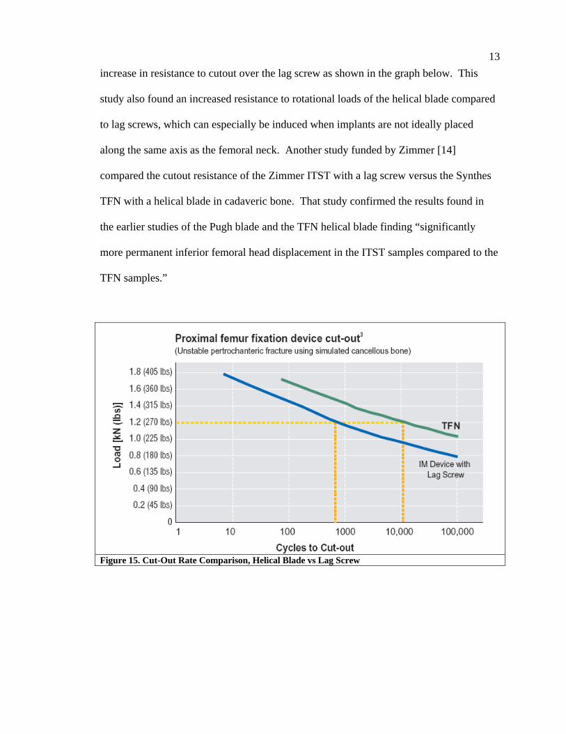
13 increase in resistance to cutout over the lag screw as shown in the graph below. This
study also found an increased resistance to rotational loads of the helical blade compared
to lag screws, which can especially be induced when implants are not ideally placed
along the same axis as the femoral neck. Another study funded by Zimmer [14]
compared the cutout resistance of the Zimmer ITST with a lag screw versus the Synthes
TFN with a helical blade in cadaveric bone. That study confirmed the results found in
the earlier studies of the Pugh blade and the TFN helical blade finding “significantly
more permanent inferior femoral head displacement in the ITST samples compared to the
TFN samples.”
Figure 15. Cut-Out Rate Comparison, Helical Blade vs Lag Screw

14
Figure 16. Rotational Stability, Helical Blade vs. Lag Screw 1.5 Z-Effect Some intramedullary intertrochanteric fracture fixation devices were designed to have
two screws inserted into the femoral head to control rotation of the femoral head. This
implant design displayed a failure mode termed the “Z-effect” in the literature and was
specific to implants that had two screws in the femoral head implanted through an
intramedullary nail. It was seen both with intertrochanteric nails that had a larger lag
screw and a smaller anti-rotation pin in the femoral head, or recon nails with two equally
sized screws in the head used to fix femoral neck fractures. These failures involved one
of the two screws migrating medially through the femoral head along its axis, which was
called the Z-effect. Sometimes one of the two screws would migrate laterally out of the
bone instead and this was termed in the literature the reverse Z-effect. These failures
have been documented in many papers, often seen with the Proximal Femoral Nail (PFN)
[17, 18, 19, 20] but also documented to occur with the Russel Taylor Reconstruction Nail
[21, 22].

15
Figure 17. Z-effect Z-effect where the proximal screw migrate medially through the femoral head in both (a) an intertrochanteric fixation nail (PFN) and (b) a reconstruction nail (RT Nail) [21]
Figure 18. Reverse Z-effect Reverse Z-effect where proximal screw migrates laterally out of the nail in both (a) an intertrochanteric fixation nail (PFN) and (b) a reconstruction nail (RT Nail) [21]
a b
a b

16 The phenomenon is not well understood. A study by Eric Strauss [21] attempted to
biomechanically understand it, although there were many limitations to the study.
1.6 Medial Migration More recently another, much more rare failure was also observed. At the time of
this study, only one case study was found [23] that documented this failure. The
percentage of cases in which medial migration happened could not be quantified because
of the rarity of its occurrence. This failure was a medial migration of a single femoral
neck implant through the femoral head, where the neck implant travelled along its own
axis through the nail and the femoral head sometimes into the acetabulum. Nobody
understood this failure and no attempt to study it was made. The case study reported by
Mark Tauber [23] called this failure “the rarest of the rare complications.” This failure
mode seems to be a result of physiologic parameters including local bone densities
through the femoral head and neck region, fracture patterns, and implant design. Even
though the failures are rare, it seems feasible that a mechanical solution could be obtained
to prevent the occurrence. Therefore if a design is capable of preventing the phenomenon
it should be pursued to prevent the typically elderly people with intertrochanteric
fractures from undergoing secondary surgery or a total hip replacement if it is
unnecessary. Some companies have tried to design implants to resist this motion, but
have been unsuccessful.

17
Figure 19. Medial Migration of Lag Screw Device. One can clearly see that the lag screw has migrated medially through the femoral head.
Before attempting to create a solution for this failure it is important to try to
understand the mechanism of the failure, or at least to try to replicate the failure in the lab
with a test model in which varying designs can be tested. The purpose of this research is
to create a biomechanical test model that would reliably reproduce the medial migration
phenomenon in a controlled lab setting. Once a robust model is achieved, various
implant designs can be tested to determine if they effectively prevent this phenomenon
from occurring. It is not our purpose to analyze or predict the parameters that might
induce medial migration. The event is rarely observed in the clinical setting. The
parameters that may be contributing to this phenomenon are numerous, difficult to
clinically assess, and there are not enough clinical cases to study. However if an implant
is to be designed that would eliminate the capability for medial migration it must be
tested. This project sets out to create a robust test model that can reliably be used to test
designs claiming to fix the problem.
18
Chapter 2: Specific Aim #1 – Mechanical Test Construct
The first goal of this project is to develop a mechanical test model to simulate
and recreate the phenomenon of medial migration of the intertrochanteric nail
fixation device.
Mechanical testing of intramedullary intertrochanteric fixation devices commonly
consisted of analyzing the two known failure modes of intramedullary devices used in
fixing intertrochanteric fractures. The first test typically performed is a standard fatigue
failure of the implant construct. This test is often performed by most manufacturers of
these devices in order to prove that their devices are at least as strong as the implants
currently used for the same fracture. Fatigue testing entails holding the distal portion of
the nail firmly in place while the femoral neck implant is cyclically loaded until the
construct catastrophically fails.
The second failure mode more recently studied concerned what is clinically
characterized as “cut-out,” which occurs when the femoral head, typically osteopenic,
falls into a varus collapse due to the poor bone quality and the neck implant cuts out of
the femoral head superiorly as a result. Cutout testing can be performed by testing the
neck implant alone, placing it into a foam head which simulates cancellous bone, or
actual cadaveric femoral heads. The lateral end of the neck implant is then held firmly,
as in a vice, while the foam head is loaded until the implant cuts out of the foam head. In
each of these two biomechanical tests the implants are securely anchored to control the
test [13].

19 2.1 Hypothesis
In contrast to the above mentioned failures, medial migration is a result of many
confluent factors and is believed at least requires motion of the nail, neck implant, and
the femoral head, which is not a condition that was previously tested. The basic
hypothesis is that medial migration is caused by a “jacking” action of the femoral neck
implant created when the nail toggles in the canal as a result of the loading and unloading
of the femoral head during activities like walking. It is believed that during loading and
unloading cycles, the nail toggles medially and laterally, advancing the femoral neck
implant much like a caulk gun. Often the lesser trochanter is broken so there is no medial
buttress for the fracture. The lack of a bony medial buttress below the axis of the neck
implant, allows this toggling motion to occur. Also, bone resorption is usually seen at the
lateral cortex around the location of the femoral neck implant, which both indicates and
allows toggling.

20
Figure 20. Hypothesis of Causes of Medial Migration
These are not the only conditions that create a situation favoring medial
migration, else these failures would be much more common. Other varying physiologic
unknowns play a seemingly large role, one of which involved local bone quality in the
femoral neck and head. The majority of the patients undergoing these hip surgeries
Broken lesser trochanter
Resorption of lateral wall
Force vector during walking
Direction of nail toggle

21 generally have osteopenic bone, which contributes to superior cutout of the neck implant
if a failure occurs. However, varying bone densities in different locales throughout the
head and neck are believed to play a role in this medial migration phenomenon. For
example, it is thought when the nail toggles laterally due to loading, the femoral neck
implant could be lightly bound in the nail due to friction between the nail and neck
implant and therefore cut medially into the femoral head, possibly only a few microns.
Then because of a source of friction between the neck implant and the femoral head, the
implant in the femoral head is held in its advanced position as the load is relieved from
the femoral head and the nail toggles to its original. Otherwise, if there was no friction
between the implant and the femoral head, the neck implant would toggle back with the
nail, as there is some friction still between the nail and neck implant. This motion,
repeated many times can advance the blade through the femoral head. Essentially, high
friction between the neck implant and nail causes the implants to bind together during
loading. As long as the friction between the nail and neck implant is higher than the
resistance to neck implant advancing medially, the implant can cut medially into the
femoral head. During unloading, as the friction between nail and neck implant is
reduced, if it drops to a level lower than the friction between the neck implant and the
bone, the neck implant is held in its new position and the nail returns.
However, other conditions need to exist for medial migration to occur. There
must be sufficient bone resorption in the lateral cortex around the neck implant,
otherwise, a tight fit between the implant and the bone would prevent toggling of the
implants. The bone quality of the femoral head must also be high enough in certain
locations to resist varus collapse of the femoral head, otherwise multiple load cycles
22 would result instead in superior cutout of the implant. However, the bone quality medial
to the implant must be low in order to be overcome by the friction between the neck
implant and the nail. Finally, there must be a specific amount of friction between the
femoral head and the neck implant. Too much friction would not allow the neck implant
to migrate medially and too little friction would not hold the neck implant in its new
place in the femoral head as the nail toggles laterally and the implant would also return to
its original position with the nail.
2.2 Test Objective In this first phase, we will attempt to create a biomechanical test model that can
replicate this motion. This model can then be used to test new nail designs that are
intended to prevent this effect. In order to design an implant that does not allow for
medial migration, this phenomenon must first be recreated in a test model so that the fix
can also be tested in the same model. Otherwise, any fixes designed will only be
theoretical and cannot be actually verified. The testing will be conducted on the Synthes
Trochanteric Fixation Nail (TFN). This experiment will also test our null hypothesis by
preventing toggling of the nail to determine if medial migration still occurs.
2.3 Phase I 2.3.1 Materials and Methods
Phase I of this specific aim is the first attempt to create a test model and involves
designing the appropriate fixtures needed to replicate this effect of medial migration. The
implant used in this part of the study is a Titanium Trochanteric Fixation Nail (TFN)
produced by Synthes. The nail is 170mm long and has a 6º proximal bend. The proximal
diameter of the nail is Ø17mm and the distal diameter of the nail tested is Ø11mm. There
23 is a 130º angle between the axis of the distal shaft of the nail and the axis of the Ø11mm
oblique hole in the proximal end of the nail through which the neck implant is placed,
commonly referred to as the neck/shaft angle.
Throughout the rest of this study, anatomic descriptions of location will be used in
describing the fixture as the different parts of the fixture mimic the anatomy. The term
medial will be used to describe anything that is toward the midline of the body, while
lateral is away from the midline. For example, the delrin head described later which is
used to mimic the femoral head would be medial to the rest of the fixture [Figure 21].
The term distal refers to the direction toward the foot, while proximal refers the direction
toward the head.
An aluminum fixture was created to hold the TFN for testing and to simulate the
intramedullary canal. It is a long rectangular block with a longitudinal, Ø15mm, hole
through the center. A Ø17mm hole is drilled at a 6º angle to the axis of the Ø15mm hole
to match the opening made during surgery for the implant at the proximal diameter of the
implant. The TFN is normally fixed distally with a Ø5mm screw placed through the
distal slot at an angle. A Ø5mm hole is drilled through the aluminum block at the
appropriate location and angle to match the location of the locking screw used with the
TFN, allowing a Ø5mm pin to hold the nail in its proper resting position. The diameter
of the helical blade placed through the nail and into the femoral head is Ø11mm.
Therefore a hole larger than Ø11mm is drilled in the lateral wall of the nail fixture to
mimic bone resorption around the neck implant which allows nail toggle. Finally, an
angled cut is made on the medial wall of the nail fixture to mimic an intertrochanteric
fracture. This cut must not cross the space where the proximal portion of the nail would

24 sit to allow for the plate described next to be affixed to the fixture. Again, the entire
construct is clearly illustrated in Figure 21.
Across the face of the cut on the fixture, a plate is attached that has an area cut out
for the femoral neck implant. Between the backside of this plate and the nail that is in the
aluminum block, a 3/8” thick piece of 70A durometer rubber elastomer is placed to
simulate the elastic properties of the nail/bone interface which allow the nail to return
toward its original position as the load is reduced.
In order create controlled conditions resistant to superior cutout, the femoral head
was simulated with a delrin head with an axial hole providing a slip fit to the implant.
Since medial migration is sensitive to the friction conditions in the femoral head as
described above, the variability of those conditions was controlled by removing the fluted
portion of the helical blade and replacing it with a round shaft of the same diameter.
Otherwise the edges of the helical blade would cut into the delrin, creating high and
unknown friction conditions. Perpendicular to the axis of this hole in the delrin head,
another hole is drilled and tapped. The thread is reinforced with a stainless steel helicoil
insert, so the plastic threads do not deform when stressed. Through the tapped hole, a
small delrin cylinder is dropped and captured with a set screw. The set screw is tightened
to a set torque driving down on the delrin bushing creating a frictional force on the
modified helical blade. This creates a controllable mechanism of creating the friction
seen by the neck implant in the delrin femoral head. The back end of the delrin head is
rounded as shown in the Figure 21. When the head is loaded, it is expected to pivot
around the rounded back end.
25
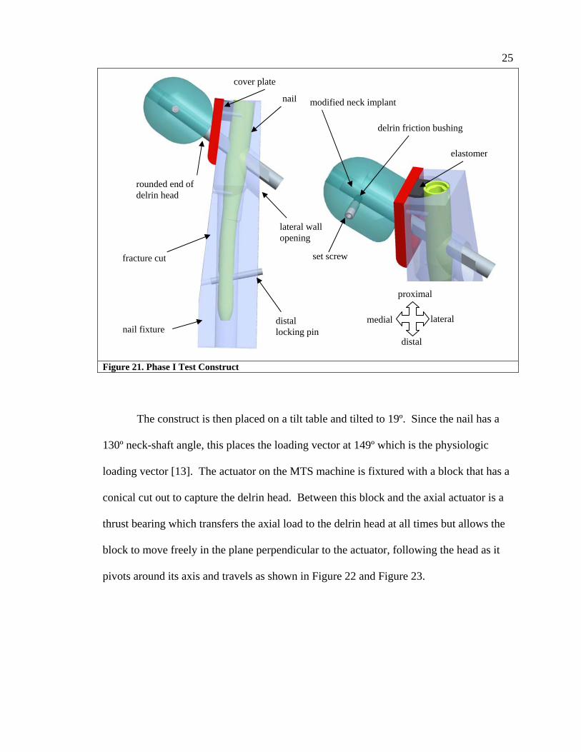
Figure 21. Phase I Test Construct
The construct is then placed on a tilt table and tilted to 19º. Since the nail has a
130º neck-shaft angle, this places the loading vector at 149º which is the physiologic
loading vector [13]. The actuator on the MTS machine is fixtured with a block that has a
conical cut out to capture the delrin head. Between this block and the axial actuator is a
thrust bearing which transfers the axial load to the delrin head at all times but allows the
block to move freely in the plane perpendicular to the actuator, following the head as it
pivots around its axis and travels as shown in Figure 22 and Figure 23.
modified neck implant
delrin friction bushing
set screw
elastomer
nail fixture
fracture cut
nail
distal locking pin
rounded end of delrin head
lateral wall opening
cover plate
proximal
distal
lateral medial

26
Figure 22. Thrust Bearing Adaptor Cross section of actuator adaptor, thrust bearing, and conical block to capture femoral head simulator
Figure 23. Thrust Bearing Action As actuator places load axially onto femoral head at physiologic load vector, thrust bearing allows free motion of actuator in perpendicular plane so as to not induce unknown forces into the test as the head pivots.
The construct is then cyclically loaded with a sinusoidal load pattern at a rate of 2
Hz. Various loads were used with the maximum loads ranging from 400 N to 1200 N
and the minimum loads ranging from 10 N to 80 N. The torque on the set screw creating
the friction was also tightened to torques ranging from 0.25 N-m to 1.5 N-m.
2.3.2 Results and Conclusions of Phase I This biomechanical construct did not exhibit any indication that the neck implant
was migrating medially under any combination of loading conditions or torques applied.
The construct upon initial loading, appeared to toggle with the first cycle, compressing
the elastomer, but no further motion was observed in the entire construct and no
migration occurred. Upon complete removal of the load, the nail, neck implant and
delrin head seemed stuck in the loaded position, and the elastomer was still compressed.
Free to travel in this plane
thrust bearing
19º
130º
Conical cutout to capture delrin head

27 The construct had to be freed with a light tap in order allow the nail to return to its
original location.
The recurrence of this incident throughout this phase of the study with various
load and friction combinations, led us to believe that something was wrong with our
initial setup and not with our range of loads and torque values. We theorized that during
initial loading, the nail toggled as expected, increasing the angle of the “V” shaped gap
between the neck implant and the cover plate. However, the delrin head did not merely
roll as expected, but instead was pushed along the axis of the neck implant, squeezing
into the increased “V” gap made due to the blade toggling medially. This caused the
delrin head to become lodged further down between the neck implant and the cover plate,
preventing the nail from toggling back to its original position when the load was relieved.
For this reason, the construct needed to be tapped free after loading. See Figure 24.

28
(a)
(b)
(c)
Figure 24. Wedge Effect (a) Load is applied (b) Head rotates, gap is created (c) Head slides along axis under load, becoming wedged in the gap, preventing the nail from toggling back. Steps (b) and (c) happen simultaneously
Therefore, this construct is not suitable for medial migration. However, this
discovery is still worth noting as it may relate to other clinical situations where the neck
implants do not slide laterally as they are expected, nor migrate forward, but the head
seems to collapse axially along the implant. Since this is also a clinically observed
condition, this might actually be an important discovery in itself. This observation lends
itself to the hypothesis that this condition might occur if the bone of the femoral neck also
wedges itself in the samve V-shaped gap between the shaft and neck axis. However more
“V” “V” increases
29 research would be required to understand how this would work and what role local bone
density would play. The bone would somehow need to be strong enough to become
wedged but still crumble, allowing collapse where the two bony fragments meet. If the
bone quality is poor enough to crumble it may not be strong enough to wedge between
the nail and neck. Further study would be required if this condition is to be further
understood.
This failure led us to then design a new “toggle joint” to create a condition
suitable for medial migration. This design is described in phase II below.
2.4 Phase II 2.4.1 Materials and Methods
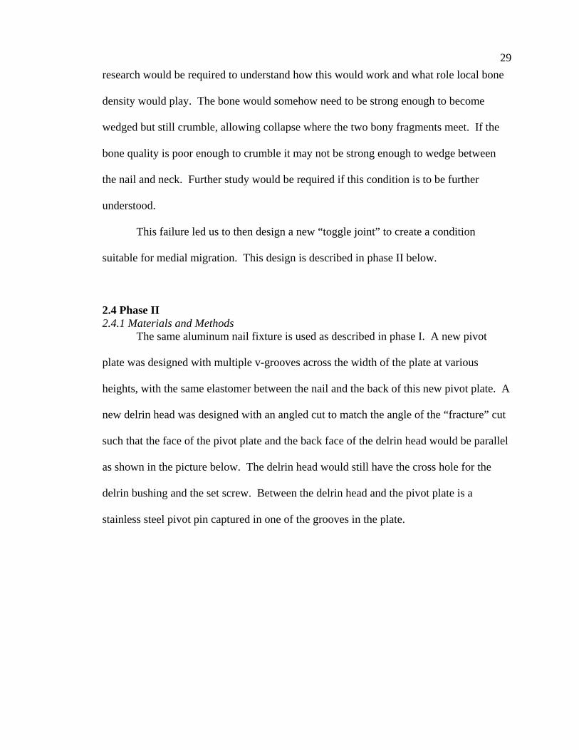
The same aluminum nail fixture is used as described in phase I. A new pivot
plate was designed with multiple v-grooves across the width of the plate at various
heights, with the same elastomer between the nail and the back of this new pivot plate. A
new delrin head was designed with an angled cut to match the angle of the “fracture” cut
such that the face of the pivot plate and the back face of the delrin head would be parallel
as shown in the picture below. The delrin head would still have the cross hole for the
delrin bushing and the set screw. Between the delrin head and the pivot plate is a
stainless steel pivot pin captured in one of the grooves in the plate.
30
Figure 25. Phase II Test Construct
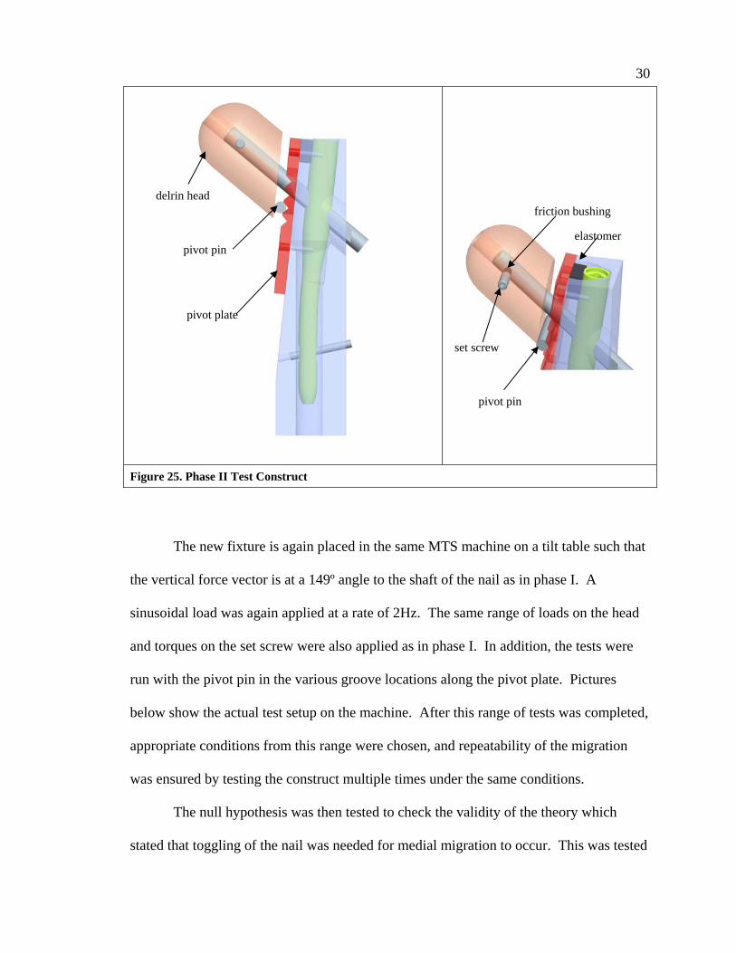
The new fixture is again placed in the same MTS machine on a tilt table such that
the vertical force vector is at a 149º angle to the shaft of the nail as in phase I. A
sinusoidal load was again applied at a rate of 2Hz. The same range of loads on the head
and torques on the set screw were also applied as in phase I. In addition, the tests were
run with the pivot pin in the various groove locations along the pivot plate. Pictures
below show the actual test setup on the machine. After this range of tests was completed,
appropriate conditions from this range were chosen, and repeatability of the migration
was ensured by testing the construct multiple times under the same conditions.
The null hypothesis was then tested to check the validity of the theory which
stated that toggling of the nail was needed for medial migration to occur. This was tested
delrin head
pivot pin
friction bushing
elastomer
set screw
pivot pin
pivot plate
31 by removing the elastomer from between the pivot plate and the nail. The pivot plate had
a thread tapped through at the location where the elastomer was. A set screw was then
threaded through the pivot plate to engage the nail and prevent it from toggling under
load. This setup was tested at a range of loads with the maximum load ranging from the
ideal load determined from the elastomer test up to a maximum of 1200N to ensure a
robust test.
Figure 26. Photo of Phase II Construct on MTS Machine 2.4.2 Results and Conclusion of Phase II
With this new setup, medial migration was observed under multiple loading
conditions of the range applied above. Within a few hundred cycles a migration of over
10mm occurred. At high set screw torques creating high friction on the neck implant and
low loads on the femoral head, no migration was readily observed. At intermediate loads
and set screw torques, migration was observed. As expected, this demonstrated part of
the delicate balance between the friction in the head on the implant and the loading
conditions. Since the purpose of this study however was not to characterize migration

32 rates because they are influenced by physiologic factors beyond our current capabilities
of measurement, we did not pursue further study of different combinations of loads and
torque values. We also found that the neck implants only showed evidence of migration
when the pivot pins were placed in a location below the axis of the neck implant. Also,
we were able to prove that toggling of the entire construct was needed for migration to
occur. When the elastomer was removed and replaced with a set screw, preventing nail
motion, no medial migration of the neck implant was observed.
2.5 Discussion We now have a working model where the phenomenon of medial migration of
femoral neck implants can be replicated. It was shown in these experiments that for the
femoral neck implant to travel medially, the nail must toggle.
It may seem that one simple fix would be to design a stiff system removing the
ability for the nail to toggle inside the canal. However this fix is neither simple nor
correct and creates other physiologic failures. One has to consider the compliance of the
bone and implant and the fact that it is being placed in a broken bone. Keeping the nail
immobile is probably not feasible. Additionally, creating a very stiff construct is also not
desirable. One of the earlier intramedullary hip fixation nails was Stryker’s Gamma Nail.
The short Gamma nail initially had two distal locking holes for cross locking screws as
shown in Figure 27. As the nail was loaded during physical activity, the stress was
transferred through those two distal locking screws to the bone as the nail was trying to
toggle. This sometimes caused fractures in the bone which began through one of the
screw holes due to the stress riser in the bone as shown in Figure 27b. Future generations
of all short cephalomedullary nails including the Gamma nail replaced their locking holes

33 with slots that allowed short nails to toggle and rest on the lateral cortex, thereby sharing
the loads between the nail and the bone. This successfully reduced the incidence of
fractures of the bone at the level of the distal locking screw in the short nail.
(a)
(b)
(c) Figure 27. Toggling Needed for Short Cephalomedullary Nails (a) Note the two locking screw holes (b) Fractures occurred through the stress riser created by the locking screws as the stress was transferred to the screws (c) Future nails were designed with a slot, allowing the nail to toggle and rest on the lateral cortex, relieving the stress and reducing the fractures.
We chose to continue further phases of the testing with a sinusoidal load cycle
where the minimum load was 40 N, the maximum load was 800 N, and the torque setting
on the set screw in the femoral head was 0.5 N-m. Although the actual load on the hip
has been studied during various physical activities and can be approximated to be two
and a half times body weight during a normal gait cycle for example [24, 25], it is
important to keep in mind that these chosen loads are not representative of physiologic
load on the implant during physical activity since the actual load on the implant is not
34 simply determined. The load on the implant is not simply equal to the joint reaction force
since the joint reaction force is distributed between the bony fragments contacting each
other, the neck implant, the nail, and the rest of the bone. How much of the load is
actually transferred to the implant depends highly again upon bone quality, implant
geometry, and the reduction of the fracture.

35
Chapter 3: Specific Aim #2 – Construct Validation in Foam Model
The second goal is to validate the model as biomechanically accurate, by
placing the actual neck implants into foam blocks that simulate the cancellous bone
of the femoral head instead of the plastic. For the construct to be considered valid,
traditional varus collapse of the femoral head model should be observed.
Since we have replicated medial migration in a simplified model we would like to
now test the model by replacing the delrin head with a head made of polyurethane foam
often used to represent cancellous bone structure. This foam was also used in the cutout
study performed by Sommers, et. al. [13]. Although we would like to see the test
construct achieve medial migration with the foam heads, this will not likely occur since
the foam heads are of uniform density. However the goal is to validate the construct by
showing that it would achieve varus collapse, which is the expected failure mode for
these foam constructs.
3.1 Hypothesis Medial migration in the foam heads is not expected. Although, for the first time,
a toggling construct is tested, the foam head does not have varying densities. The foam
head used is of uniform density, which when tested to failure is expected to demonstrate
varus collapse. If medial migration does occur in this model, it would be expected to
occur at a much higher rate clinically.

36 3.2 Test Objective
The objective of this test is to examine the results when testing the construct
developed in specific aim #1 with a foam head instead of the delrin head. We want to
validate the model by showing that it responds to constant cyclic loading with a failure
mode that is clinically observed. If the construct does not exhibit the expected varus
collapse under loading it may have to be redesigned to provide the desired response. A
redesign would then require a retest of the methodology performed during specific aim 1.
3.3 Phase I 3.3.1 Materials and Methods
The aluminum tube, nail, cover plate, 130° nail, and elastomer from the earlier
testing will be used. A new femoral head will be developed for this test. A foam head
will be machined into a shape resembling the delrin head. The foam, however, can
crumble under the loading actuator, so in order to distribute the load evenly through the
head and not crumble the section in contact with the actuator, the foam head will be
encapsulated in a two piece stainless steel shell that is 5mm thick, composed of a shell
and a back plate capturing the foam head in the shell. The construct will look like the
one in Figure 28.
The foam used is a cellular rigid closed cell polyurethane foam purchased from
Sawbones Worldwide, A Division of Pacific Research Laboratories, Inc.,
(www.sawbones.com ). Two types of foam were used which are summarized in the table
below. The foam does not have the mechanical properties of typical cancellous bone but
is commonly used by industry in mechanical tests where a simulated cancellous bone
material is required. It was also used in the testing performed at Legacy Labs on various
femoral neck implants where cutout was simulated [13].
37
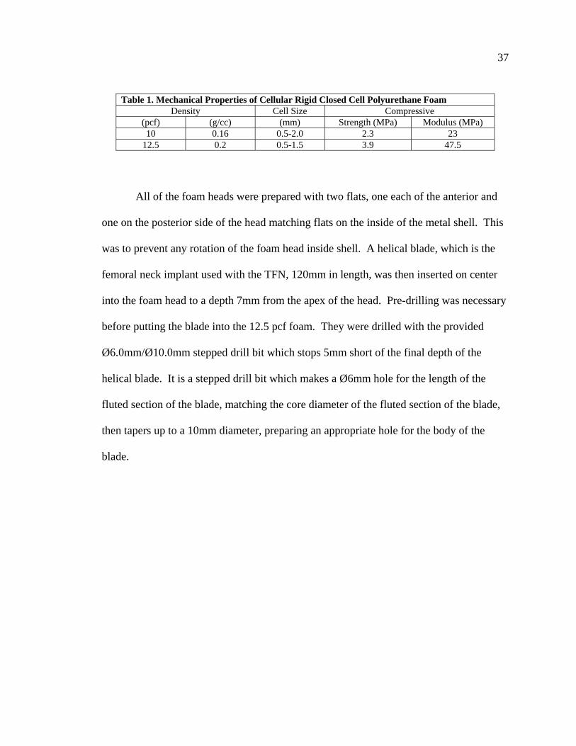
Table 1. Mechanical Properties of Cellular Rigid Closed Cell Polyurethane Foam Density Cell Size Compressive
(pcf) (g/cc) (mm) Strength (MPa) Modulus (MPa) 10 0.16 0.5-2.0 2.3 23
12.5 0.2 0.5-1.5 3.9 47.5
All of the foam heads were prepared with two flats, one each of the anterior and
one on the posterior side of the head matching flats on the inside of the metal shell. This
was to prevent any rotation of the foam head inside shell. A helical blade, which is the
femoral neck implant used with the TFN, 120mm in length, was then inserted on center
into the foam head to a depth 7mm from the apex of the head. Pre-drilling was necessary
before putting the blade into the 12.5 pcf foam. They were drilled with the provided
Ø6.0mm/Ø10.0mm stepped drill bit which stops 5mm short of the final depth of the
helical blade. It is a stepped drill bit which makes a Ø6mm hole for the length of the
fluted section of the blade, matching the core diameter of the fluted section of the blade,
then tapers up to a 10mm diameter, preparing an appropriate hole for the body of the
blade.

38
Figure 28. Foam Head Construct. Construct will be the same as the final construct described in specific aim #1, except with a real helical blade and foam head captured in a steel shell
The foam heads were sturdily fixtured and the helical blade was hammered in
with the proper starting orientation to attain the desired final orientation and depth in the
foam head model. Helical blades were inserted into 10 pcf foam heads, half of which
were predrilled with the stepped drill bit and half of which were not predrilled. As stated
earlier, the 12.5 pcf foam heads were always predrilled since they were too dense to
insert the blade without predrilling.
The entire fixture then was placed on the tilt table at an angle of 19° as before and
loaded with a sinusoidal load pattern with a minimum load of 40N and a maximum load
of 800N at a frequency of 2Hz, according to what was determined to be acceptable in
phase 1 of the research. If medial migration of the helical blade occurred under any of
the tested conditions, then again the null hypothesis would be tested, replacing the

39 elastomer with a set screw, which would remove the nail toggle from the system. The
expected result of this would be varus collapse of the foam femoral head.
3.3.2 Results and Conclusion of Phase I Neither of the expected results were achieved during this part of the
experimentation. It was expected that this model which provided us with medial
migration when testing with a delrin head would exhibit one of the failure modes
observed clinically. Instead, in every configuration of foam head/blade combination, a
valgus rotation of the femoral head resulted, opposite of the expected varus rotation as
shown in Figure 29. This condition is not documented to be an observed clinical failure
of any of the existing cephalomedullary implants. Therefore, this biomechanical
construct with the delrin head is not valid for testing implants.
The construct must be redesigned and validated with results matching those
clinically demonstrated. We believe that the relatively vertical fracture pattern in the
construct combined with the pin between the two segments allowed the head to roll
backward more freely. As the loading force is transferred through the pivot pin, the
reaction forces normal and parallel to the face of the fracture now sitting at 25° to the
vertical (19° of the tilt table plus the 6° fracture angle) have a larger component in a
vector parallel to the face of the fracture. Subsequently, the head traveled in that
direction. Also, our model had a gap between the two segments which normally does not
exist clinically. Often, as soon as the patient begins weight bearing, any gap that may
have existed between the lateral and medial segments disappears as the medial segment
collapses. In fact, medial migration is almost always seen after some initial collapse.

40
Figure 29. Valgus Rotation of Foam Construct Arrows (A) and (B) indicate the expected failure modes, varus rotation of the femoral head, or medial migration of the neck implant, respectively
Arrow (C) shows the resulting valgus rotation, which included a large distal sliding component.
Force D, transferred to the pin and broken into components E & F has a larger force in the direction of vector F. The head therefore travels more in that direction resulting in a rotation due to the gap between segments
A new test fixture must be designed and tested according the testing outlined in
this section. Then, if it proves to be a valid model, it must be tested per specific aim #1
to check if the new model can still mimic medial migration.
3.4 Phase II 3.4.1 Materials and Methods
A new fixture was designed to resist vertical sliding of the femoral head and
remove the gap between the segments. The same aluminum tube and nails will be used.
The grooved cover plate however will be replaced with a new plate that changes the
A
B
C
D
E
F
D
gap

41 angle of the fracture between the two segments and provides a place to hold pins to allow
for rotation, yet make contact with the femoral head segment, removing the gap. Both
parts of the femoral head shell will also be modified. The back end of the shell will not
have an angled cut to match the angle of the fracture, but will instead be cut
perpendicular to its axis. This is not critical to the test but it is easier to design the back
cover plate of the shell with different angles than to create entire shells with different
angles. The back plate of the femoral head component will have an angled cut to match
the angle of the simulated fracture. Instead of a 6° fracture angle which is almost
vertical, the new fracture angle will be 45 degrees. This is accomplished by making a
plate that has a 20° face that is placed on the fracture surface, making a total fracture
angle of 26°. When the fixture is placed on the tilt table at an additional 19°, the sum
becomes 45°. This plate also has pockets to hold pins for the head to pivot around. Then
the back plate for the head fixture will have a cut 14° to the plane perpendicular to the
axis of the blade, creating a plane which mates with the cover plate of the aluminum tube.
It is hoped that by creating a 45° reaction angle and removing the gap between the
fixture cover plate and the head back plate, a torque is induced around the pivot pins
instead of the sliding action which caused the head to roll backward previously. The rest
of the testing would then be completed as before, with the same sinusoidal loading curve
at a frequency of 2Hz.
Again, foam heads of both the 10 pcf and 12.5 pcf densities will be tested. The
12.5 pcf foam heads will always be predrilled with the 6.0mm/10.0mm stepped drill bit
as described earlier before inserting the blade to a depth 7mm from the apex of the head.

42 Half of the 10 pcf foam heads will also be predrilled, while the other half will not be
predrilled like the testing during phase I.
Figure 30. Fixture With New Reaction Angle Remember fixture will be on tilt table at 19°, 26° + 19° = 45°
If this new construct with the foam head successfully demonstrates the typical
varus rotation of the femoral head around the neck implant, but not medial migration,
then the construct must be tested with a delrin head according to the protocol developed
in the first specific aim, to determine if this model can be consistently used to recreate
medial migration. A delrin head shaped like the current foam head will be made to fit
pockets for pins
20º
130°
90°
26°
130 -90 -26 14°
43 inside the stainless steel shell, with the same anti-rotation flats as the foam head. The
helical blade will again be replaced by a smooth shaft, as was done throughout the testing
for the first specific aim, with a minimal slip fit in the delrin head. A hole perpendicular
to the axis of the neck implant will house the delrin friction plug. A tapped hole in the
stainless steel shell (two can be seen in the picture above) matching the location of the
hole in the delrin head will hold the set screw used to create the frictional hold on the
implant as described in the first test performed in this research. The delrin head model
will then be tested in the same manner as the established test protocol. The fixture will
be placed on the tilt table at 19° and the head will be loaded with a sinusoidal load
pattern, with a minimum load of 40N and a maximum load of 800N at a frequency of
2Hz. The friction on the smooth neck implant will be again maintained by tightening the
set screw on the delrin plug to a torque of 0.5 N-m.
3.4.2 Results and Conclusion of Phase II Changing the reaction angle and removing the gap between the segments created
the desired result in the foam heads. Both densities tested, whether predrilled or not
proceeded to a varus failure of the head around the implant without any noticeable
medialization of the neck implant. The varus collapse is a positive indication that the test
construct is valid.
The subsequent set of tests which replaced the foam heads and helical blades with
the delrin heads and smooth shafts also resulted in the desired medialization of the neck
implant as before. It was important to validate the new construct in the delrin head in
order to ensure that by making the stainless steel head shell and aluminum cover plate

44 contact each other we did not introduce any factors that would have caused the head to
wedge itself as we previously experienced.
We were unable to attain a medialization of the femoral neck implant through the
foam head, but successfully demonstrated it in the delrin heads, strengthening our beliefs
about the complexity of interactions needed for this phenomenon. It is our belief that
medialization of the neck implant is highly related to varying densities of bone within the
femoral head and neck, resisting varus cutout (dense bone superior to the blade), allowing
medialization (low density bone medial to the blade), and maintaining a frictional grip on
the blade, possibly somewhere in the femoral neck. These conditions, along with a
fracture pattern with a pivot point below the axis of the implant, bone resorption of the
lateral cortex around the shaft of the neck implant, and a toggle and return action of the
nail in the canal all seem to be necessary combinations for medial migration to occur.
We can now, after all of the testing performed thus far, conclude that we have a
valid and robust model that can reproduce medial migration in an intramedullary
intertrochanteric fixation device. We have shown in the introduction that although rare,
this failure occurs with all such devices, whether they use one neck implant or two, and
whether those neck implants are screws or helical blades. The last part of this research is
to analyze some of the current fixation devices from various manufacturers by testing
them in this fixture to determine if they have any features that purposefully or
accidentally work to reduce the frequency of this failure.

45
Chapter 4: Specific Aim #3 – Testing Other Implant Designs For Medial Migration
The third goal of this project is to evaluate various implants from different
manufacturers on our validated biomechanical test model to determine if any
implant designs inherently prevent this phenomenon from occurring.
In this phase, various implants from different manufacturers are tested in our
model to understand if some of the different designs purposefully or accidentally
influence the implant’s ability to migrate medially. We plan on testing five different
trochanteric fixation devices: (1) Synthes’ Trochanteric Fixation Nail (TFN), (2) Synthes’
Proximal Femoral Nail (PFN), (3) Synthes’ PFN-A, (4) Stryker’s Gamma3, and (5)
Smith & Nephew’s Intramedullary Hip Screw (IMHS). The Synthes TFN will represent
a titanium construct, the Synthes PFN will represent two screw devices, the Synthes
PFN-A will represent a neck implant with shaft that is not completely circular, the
Stryker Gamma3 will represent a screw device with a claimed lower frictional coating,
and the Smith & Nephew IMHS will represent a device where the lag screw is placed
through a sleeve in the nail. Note that the PFN and PFN-A are only available in Europe.
It is evident that some of the manufacturers are aware of the issue and have tried
to design implants that reduce its ability to happen, but have not been wholly successful.
For example, Stryker’s original Gamma lag screw had 4 axial grooves along the shaft
which engaged with a set screw to control rotation of the screw after final seating. The
next generation Gamma3 lag screw tapered the 4 axial grooves. They advertise that the
grooves are ramped along the axis of the screw, and when engaged with the nose of the
set screw to control rotation, the lag screw can collapse freely in the lateral direction, but
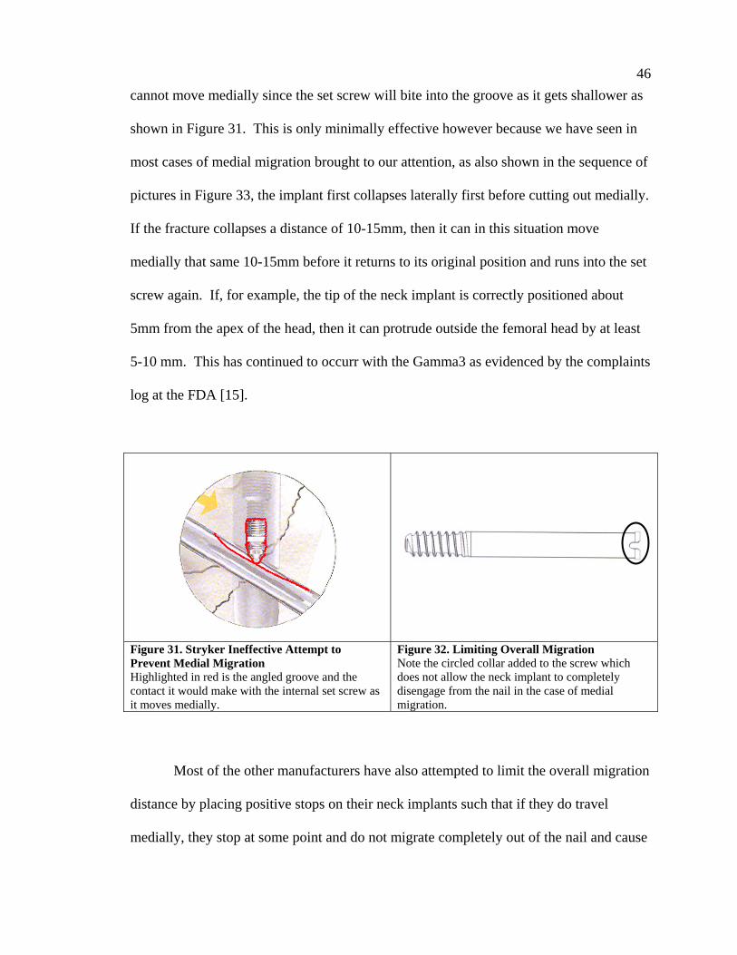
46 cannot move medially since the set screw will bite into the groove as it gets shallower as
shown in Figure 31. This is only minimally effective however because we have seen in
most cases of medial migration brought to our attention, as also shown in the sequence of
pictures in Figure 33, the implant first collapses laterally first before cutting out medially.
If the fracture collapses a distance of 10-15mm, then it can in this situation move
medially that same 10-15mm before it returns to its original position and runs into the set
screw again. If, for example, the tip of the neck implant is correctly positioned about
5mm from the apex of the head, then it can protrude outside the femoral head by at least
5-10 mm. This has continued to occurr with the Gamma3 as evidenced by the complaints
log at the FDA [15].
Figure 31. Stryker Ineffective Attempt to Prevent Medial Migration Highlighted in red is the angled groove and the contact it would make with the internal set screw as it moves medially.
Figure 32. Limiting Overall Migration Note the circled collar added to the screw which does not allow the neck implant to completely disengage from the nail in the case of medial migration.
Most of the other manufacturers have also attempted to limit the overall migration
distance by placing positive stops on their neck implants such that if they do travel
medially, they stop at some point and do not migrate completely out of the nail and cause

47 damage to the internal organs such as the bladder. For example, the Synthes PFN and the
Depuy Ace Trochanteric Nail, both of which are two-screw devices which incur a higher
failure due to the “Z-effect,” added collars to the back ends of their lag screws after
incidents where screws migrated completely through the nail. All of the implants
mentioned have an automatic positive stop except for the Stryker Gamma nailing systems
and the Zimmer Intertroch/Subtroch Nail (ITST). The ITST uses a similar set screw
engaging technique as the Gamma, but the grooves are not angled. If the surgeon
engages the grooves with the set screw then at the end of the groove a positive stop is
encountered, but if the surgeon does not engage the lag screw as they sometimes choose
not to do, then no positive stop is encountered.
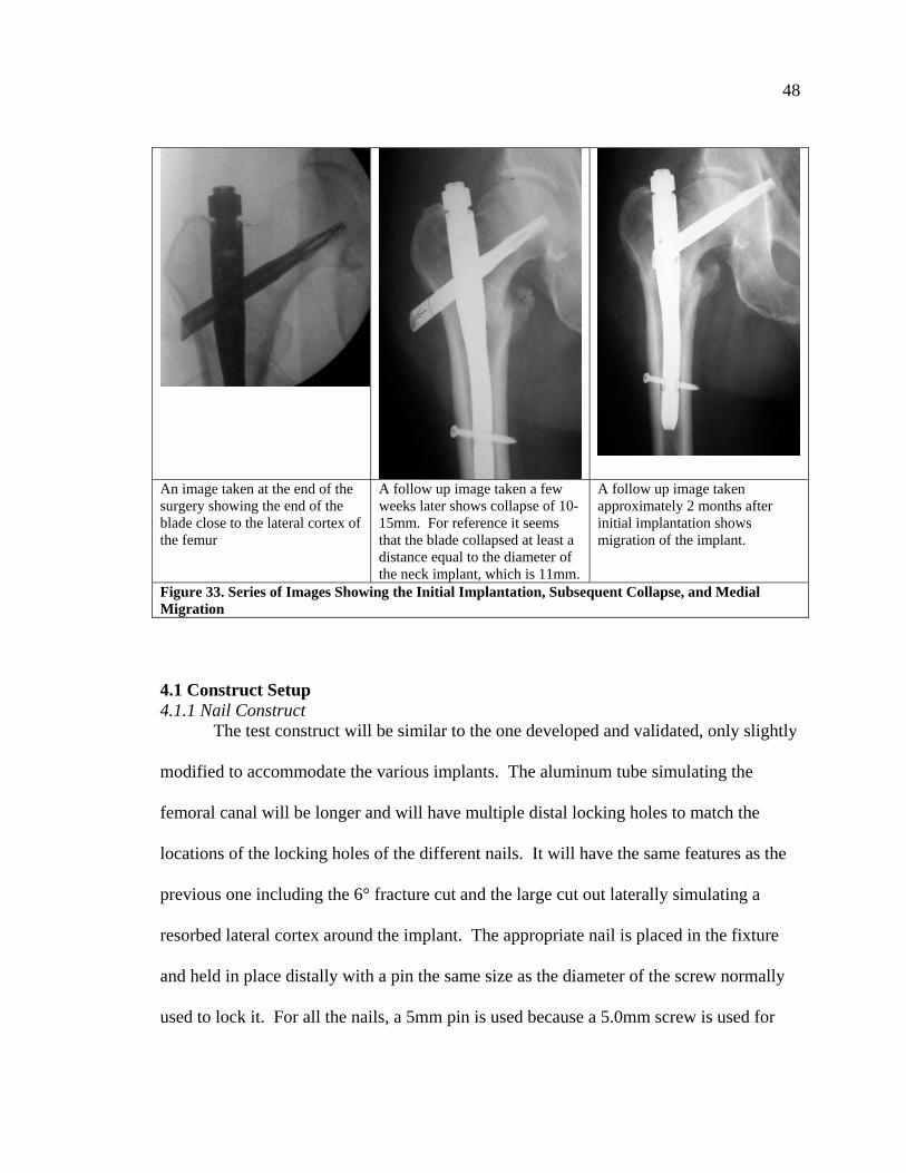
48
An image taken at the end of the surgery showing the end of the blade close to the lateral cortex of the femur
A follow up image taken a few weeks later shows collapse of 10-15mm. For reference it seems that the blade collapsed at least a distance equal to the diameter of the neck implant, which is 11mm.
A follow up image taken approximately 2 months after initial implantation shows migration of the implant.
Figure 33. Series of Images Showing the Initial Implantation, Subsequent Collapse, and Medial Migration 4.1 Construct Setup 4.1.1 Nail Construct
The test construct will be similar to the one developed and validated, only slightly
modified to accommodate the various implants. The aluminum tube simulating the
femoral canal will be longer and will have multiple distal locking holes to match the
locations of the locking holes of the different nails. It will have the same features as the
previous one including the 6° fracture cut and the large cut out laterally simulating a
resorbed lateral cortex around the implant. The appropriate nail is placed in the fixture
and held in place distally with a pin the same size as the diameter of the screw normally
used to lock it. For all the nails, a 5mm pin is used because a 5.0mm screw is used for

49 distal locking except for the IMHS which will use two 4.5mm pins to match the two
4.5mm screws typically used with the nail. The distal locking holes are positioned in the
fixture such that the top of each nail lines up with the top of the fixture. The medial side
of the aluminum fixture will use the same pivot plate developed in specific aim #2 phase
II. The pivot plate can be placed in either of two locations such that the axis of the pivot
pins is 32mm or 37mm from the top of the aluminum fixture. All of the nail constructs
will be tested at both locations except for the PFN which only be tested in the top
position because it will not fit in the lower location around this nail. Between the nail
and the pivot plate, the same 70A durometer elastomer, 3/8” thick, is placed to simulate
the elastic properties of the nail/bone interface, thus allowing the nail to return toward its
original position as the load is reduced. Again each implant construct will also be
subsequently tested in a condition where it is not allowed to toggle by replacing the
elastomer with a set screw, to verify the null hypothesis.
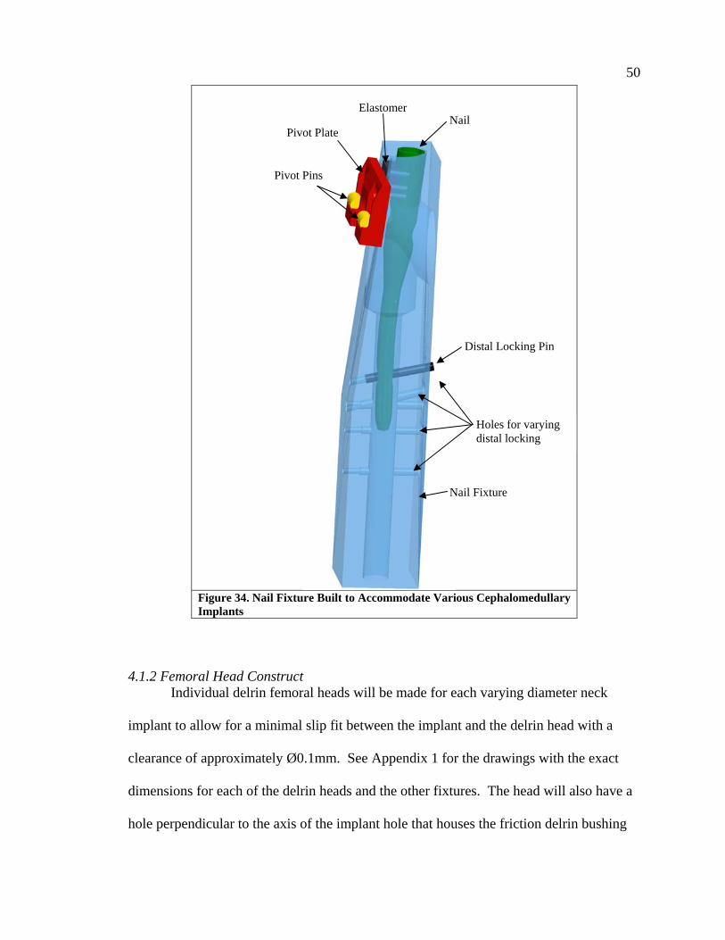
50
Figure 34. Nail Fixture Built to Accommodate Various Cephalomedullary Implants
4.1.2 Femoral Head Construct
Individual delrin femoral heads will be made for each varying diameter neck
implant to allow for a minimal slip fit between the implant and the delrin head with a
clearance of approximately Ø0.1mm. See Appendix 1 for the drawings with the exact
dimensions for each of the delrin heads and the other fixtures. The head will also have a
hole perpendicular to the axis of the implant hole that houses the friction delrin bushing
Distal Locking Pin
Holes for varying distal locking
Nail Fixture
Nail Elastomer
Pivot Plate
Pivot Pins
51 which is 8mm in diameter. The delrin heads will be made to fit inside the same stainless
steel shell used earlier with the two anti-rotation flats. The heads have a length of 53mm
and an outer diameter of Ø45mm. The steel shell will also have tapped holes that line up
with the holes in the head for the delrin friction bushing. A set screw is threaded through
the metal shell on top of the friction bushing to 0.5N-m of torque, creating a consistent
frictional force on the neck implant inside the delrin head.
Lag screws and helical blades are also modified, cutting off the threaded portion
or helical blade portion and replacing them with a smooth shaft matching the outer
diameter of each implant. This allows consistent control of the friction on the implant
inside the delrin femoral head. The crests of the threads and edges of the flutes otherwise
would cut into the inside of the delrin head and introduce additional unknown and
uncontrolled frictional variables that can also resist the desired motion. The length of the
lag screw is not critical as long as the same length screw is inserted. These implants were
modified to be 115mm long overall to allow them to fit in the fixture, except for the
superior screw on the PFN. That was made to be 107mm long as it is supposed to be
shorter than the distal screw. A hole was also tapped at the apex of the shell which
allowed for a setup tool to be inserted. The neck implant would then be inserted until it
made contact with the setup tool before the friction bushing is engaged, ensuring that all
implants are inserted to the same 15mm depth from the inside of the metal shell. Also,
since the PFN is a two screw device, the delrin head and steel shell are modified such that
friction bushings engage both lag screws during the testing.

52
Figure 35. Head construct
It is important to note any necessary orientation of the neck implant in the delrin
head before tightening the set screw. For example, the TFN has an anterior flat which
engages with an anti-rotation locking mechanism in the nail that should be properly
oriented. The Gamma3 lag screw has the grooves mentioned earlier that engage with the
set screw. We are assuming that the lag screw has already collapsed 15mm and therefore
the set screw may only minimally engage the groove, allowing it to migrate medially
15mm. Due to length requirements of the neck implants, the grooves were not long
enough to be engaged so we did not engage the set screw given that we were not worried
about rotation in this construct. The other implant for which orientation was important
for the test is the IMHS lag screw. The lag screw is designed to fit through a sleeve
which has two internal flats that engage flats on the screw to prevent rotation. Clinically,
the orientation of those flats is not relevant. For this test the flats must be oriented such
that they face proximally and distally. Otherwise, the delrin bushing which engages the
Setup Tool
Metal Shell
Delrin Head
Back Plate
Femoral Neck Implant
Delrin Friction Pin
Set Screw

53 anterior side of the implant will first engage the fully round portion of the screw, but as
the screw migrates, the bushing will slip onto the flats and lose its hold.
Figure 36. Flats on IMHS Lag Screw
4.1.3 LVDT Attachment In order to quantify the medialization, we will also attach a linear variable
displacement transducer (LVDT) to the blades to measure the amount of migration
experienced over a certain number of load cycles. The LVDT used was from Omega
Engineering, Inc., model number LD310-10. Since the femoral neck implants were all
cannulated to begin with, we kept them cannulated after the modifications we made to
them. We then fed a flexible 1mm multifilament cable with a stop through the neck
implant to be attached to the LVDT via an adaptor. In order to measure the relative
motion of the blade to the nail, we had to attach the LVDT to the nail. Fixtures were
made specific to each nail. Each nail had a different sized notch proximally to allow for
the respective manufacturers’ insertion handles, with mating tangs, to connect to the nail
and provide rotational control to the user. We made connection barrels with the
flat

54 appropriate mating tangs to connect to each nail. The barrels were coupled with an arm
which clamped the LVDT in line with the neck implant. Holding the LVDT arm and the
connection barrel to the nail was a connecting screw with the corresponding thread
appropriate for each nail.
Figure 37. Final Construct Used for Testing the Various Implants 4.1.4 List of Implants Gamma3 Construct (5 of each) Nail: Ø11mm x 180mm x 130˚ p/n: 3130-1180S Lag Screw: Ø10.5mm x 95mm p/n: 3060-0095S – modified as described above
Connecting Screw Nail Connection Barrel LVDT Arm
LVDT
Cable
LVDT Connection Adaptor

55 IMHS Construct (5 of each) Nail: Ø12mm x 210mm x 130˚ p/n: HN3012 Sleeve p/n: HN1200 Set Screw p/n: HN1202 Lag Screw: p/n: 12-1178 – modified as described above TFN Construct (5 of each) Nail: Ø11mm x 170mm x 130˚ p/n: 456.318 Blade: Modified as described above PFN Construct (5 of each) Nail: Ø11mm x 240mm x 130˚ p/n: 473.231 Lag Screw p/n: 473.120 Modified as described above Hip Pin p/n: 439.095 Modified as described above, but
overall length was 107mm PFN-A Construct (5 of each) Nail: Ø10mm x 240mm x 130˚ p/n 472.265 Helical Blade: Blade portion replaced with smooth shaft as described below.
4.2 Procedure The LVDT has to be calibrated before use. It is connected to a signal conditioner,
also from Omega Engineering, Inc., model number LDX-3A. The signal conditioner
feeds an analog input into the TestStar IIm controller. The LVDT is held in its
compressed state and the readings are tared. Then it is extended to 3mm, 6mm, and 9mm
and the readings in volts are recorded. This is repeated three times. A best fit curve then
is calculated and used to convert the subsequent computer readings to actual linear
displacement of the neck implant.
Five nails of each of the five implants are to be tested. Each construct will be
tested three times, once with the axis of the pivot pins 32mm from the top of the
aluminum construct, and again at 37mm from the top. The third trial will replace the
elastomer with a set screw clamping the nail from moving, ensuring that if medial

56 migration is exhibited, nail toggle is still a major contributing factor as we first
hypothesized. For the third trial, the pivot plate should be placed in whichever location
showed the quickest lateralization of the implant. This amounts to 75 total trials: 5
different types of nails x 5 nails of each type x 3 trials each = 75.
Each nail is placed in the construct as described above. Modified neck implants
are appropriately positioned in the head construct clamped down with a set screw on a
delrin bushing tightened to 0.5 N-m, and the cable is fed through the cannulation. The
LVDT is connected, ensuring its arm is not fully extended or fully collapsed but can
move in either direction recording either medial migration or lateral collapse, and then
the entire construct is placed on a tilt table at 19°. A sinusoidal load is applied from 40N-
800N at a frequency of 2Hz. The test is set to stop after the LVDT has recorded 9mm of
medial migration, or after 5,000 cycles have passed, whichever comes first.
4.3 Results and Discussion From the LVDT calibration shown in Table 2 below, the test was stopped when
the signal conditioner output -3 volts, which corresponded to 9mm of displacement, or
after 5,000 cycles were reached.
Table 2 LVDT Calibration Data LVDT Calibration Readings (V) Distance (mm) Trial 1 Trial 2 Trial 3 Average
3 -1.05 -1.00 -1.05 -1.03 6 -2.05 -2.01 -2.08 -2.05 9 -3.00 -2.98 -3.09 -3.02
None of the implants from any manufacturer demonstrated the ability to restrict
medial migration. With a few exceptions, most of the implants all failed with
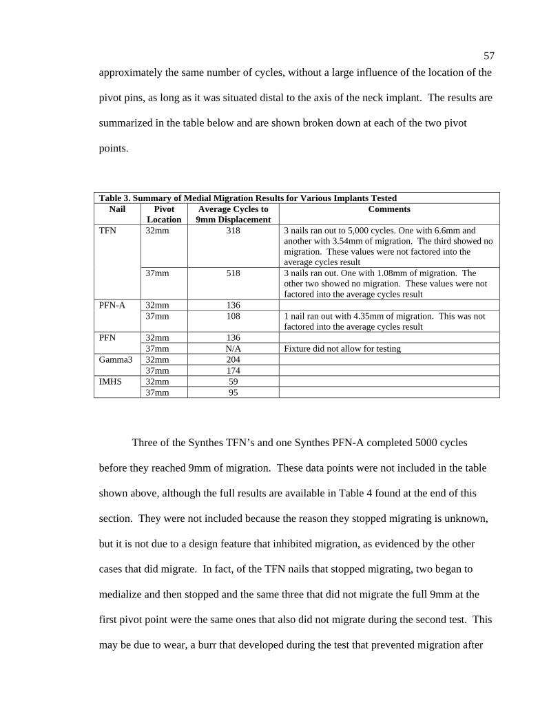
57 approximately the same number of cycles, without a large influence of the location of the
pivot pins, as long as it was situated distal to the axis of the neck implant. The results are
summarized in the table below and are shown broken down at each of the two pivot
points.
Table 3. Summary of Medial Migration Results for Various Implants Tested Nail Pivot
Location Average Cycles to
9mm Displacement Comments
32mm 318 3 nails ran out to 5,000 cycles. One with 6.6mm and another with 3.54mm of migration. The third showed no migration. These values were not factored into the average cycles result
TFN
37mm 518 3 nails ran out. One with 1.08mm of migration. The other two showed no migration. These values were not factored into the average cycles result
32mm 136 PFN-A 37mm 108 1 nail ran out with 4.35mm of migration. This was not
factored into the average cycles result 32mm 136 PFN 37mm N/A Fixture did not allow for testing 32mm 204 Gamma3 37mm 174 32mm 59 IMHS 37mm 95
Three of the Synthes TFN’s and one Synthes PFN-A completed 5000 cycles
before they reached 9mm of migration. These data points were not included in the table
shown above, although the full results are available in Table 4 found at the end of this
section. They were not included because the reason they stopped migrating is unknown,
but it is not due to a design feature that inhibited migration, as evidenced by the other
cases that did migrate. In fact, of the TFN nails that stopped migrating, two began to
medialize and then stopped and the same three that did not migrate the full 9mm at the
first pivot point were the same ones that also did not migrate during the second test. This
may be due to wear, a burr that developed during the test that prevented migration after

58 some time, or other characteristics including surface finish of the implants or tolerance
between the hole in the nail and the outer diameter of the neck implant. However the
most important thing to note is that each type of nail did exhibit medial migration
characteristics and none of the implants had a design that inherently prevented medial
migration.
An unexpected phenomenon occurred with the third trial of this phase of the
testing. When the elastomer was replaced with a set screw that prevented the nail from
toggling completely, none of the implants showed any indication of medial migration,
except for the PFN. The PFN, a two-screw device, however continued to show migration
of the inferior femoral neck element every time, with an average of 552 cycles to
complete 9 mm of migration. The proximal femoral neck element, although not
connected to an LVDT did not visually appear to migrate during these tests.
An additional trial was performed duplicating this one in every way, except that
the superior femoral neck implant was removed from the test construct. This time, no
migration was found. The additional neck element must have a secondary effect
increasing the proclivity for these implants to migrate. This may begin to explain why
the “Z-effect” was so commonly reported in the literature for two-screw devices like the
PFN and the Depuy Ace Trochanteric nail and other recon nails and given the name “Z-
effect,” but almost never reported for any of the other implants. It could be that the
thinner, proximal screw, acts like the elastomer, providing a repelling force that returns
the minimal deflection of the lag screw. This is not yet well understood but is a
considerable discovery that supports the clinical observations that two-screw devices

59 have a higher chance of medial migration, also called the “Z-effect” under the right
conditions.

60
Table 4. Detailed Results of Medial Migration Testing Per Implant Implant Elastomer - 1st pivot Elastomer - 2nd Pivot Set Screw (2-Screw) Set Screw (1-Screw)
Cycles Travel (mm) Cycles Travel (mm) Cycles Travel (mm) Cycles Travel (mm) PFN 1 145 9 416 9 5000 0 PFN 2 116 9 745 9 5000 0 PFN 3 130 9 547 9 5000 0 PFN 4 120 9 336 9 5000 0 PFN 5 170 9
N/A N/A
714 9 5000 0 TFN 1 82 9 53 9 5000 0 TFN 2 5000 6.6 5000 0 5000 0 TFN 3 5000 0 5000 0 5000 0 TFN 4 5000 3.54 5000 1.08 5000 0 TFN 5 554 9 465 9 5000 0 PFN-A 1 47 9 69 9 5000 0 PFN-A 2 61 9 62 9 5000 0 PFN-A 3 65 9 77 9 5000 0 PFN-A 4 313 9 5000 4.35 5000 0 PFN-A 5 194 9 222 9 5000 0 Gamma3 1 317 9 194 9 5000 0 Gamma3 2 145 9 215 9 2983* 0 Gamma3 3 190 9 159 9 5000 0 Gamma3 4 100 9 102 9 5000 0 Gamma3 5 257 9 198 9 5000 0 IMHS 1 64 9 168 9 5000 0 IMHS 2 50 9 54 9 5000 0 IMHS 3 67 9 96 9 5000 0 IMHS 4 64 9 78 9 5000 0 IMHS 5 49 9 58 9 5000 0 *Fixture broke, testing was stopped - most likely would have runout also
61
Chapter 5: Final Conclusion/Future Research This study proved to be very challenging, but even our initial failures provided us
with insight to other clinical occurrences of intramedullary hip fixation constructs. Many
things were learned or accidentally discovered during the progress of this study. In the
first phase we accidentally discovered a possible explanation for instances where the
femoral head collapsed along the axis of the neck implant but the neck implant itself does
not collapse along its axis with the bone as it was expected. It might possibly be due to
bone wedging into the “V” shape between the nail and the neck implant during the
collapse that prevents the neck implant from further sliding.
We also stumbled on a different mechanism that seems involved in creating the
“Z-effect,” which is particular to two-screw devices used to fix the same fractures. These
failures are clinically observed at higher rates and were reported more frequently in the
literature. The fact that the PFN implants migrated when they were not allowed to toggle
helps validate our test model, and hints that another mechanism is involved in this failure
specific to two-screw devices. We did not study this event further because it was not the
purpose of this study. We believed that our resources were better utilized understanding,
and later fixing, medial migration for single screw devices because they are used by most
manufacturers. With the rising number of intertrochanteric fractures amongst a
population that is living longer, we would like to eliminate, if possible, this failure mode,
reducing the number of secondary surgeries needed, especially for the elderly.
It is very difficult to predict whether medial migration will occur by looking at the
implant and fracture pattern. We did outline certain conditions that we thought to be
critical in allowing medial migration. The major factor included a missing lesser

62 trochanter which removes the medial buttress support allowing much of the toggle.
Evidence of toggling after the fact can be seen sometimes by a lucency of the lateral
cortex around the neck implant. However that is where visible signs end. Most
intertrochanteric or pertrochanteric fractures involve a missing medial buttress and so we
know that this is not the only condition needed. The rest of the conditions that we believe
to be necessary are not visible to the naked eye or easily measured by other means. Per
the testing, the other factor that seems to affect medial migration is the local bone density
within different areas of the femoral head and neck. The bone proximal to the implant
should be resistant to superior cutout, and the bone in other areas that contact the neck
implant should create a frictional hold on the implant less than the friction between the
nail and neck element during loading, but higher than that during unloading. As the
implants of different manufacturers have different surface finishes the friction needed can
vary from implant to implant. The rarity of the occurrence also makes it difficult to study
clinically.
The purpose of our test was not to be able to predict the behavior but to develop a
test model that could replicate the phenomenon in order give us a way to test potential
fixes. We believe that after all of the testing that was done we have successfully
developed a test model.
The challenge now lies in creating a device that can resist this failure because,
although rare, is a rather severe failure. If gone unnoticed the neck implant can pierce the
acetabulum and depending on its progress pose a risk of piercing the bladder. Measures
have been taken by most device manufacturers to limit the total overall migration of the
implant to prevent them from going so far that they migrate out of the nail completely.

63 None are successful in preventing medial migration. Some work has begun in this effort,
although our initial attempts were unsuccessful. We had designed a mechanism that
deployed a lever arm that engaged the top surface of the neck implant at an acute angle.
The concept was to create a frictional lock with the implant, preventing medial motion,
but still allow it to slide freely laterally as shown in Figure 38. We tried the concept, with
varying angles between the arm and the implant, and tried varying the contact between
the two, from line contact, to point contact and variations in between. When handling the
prototypes by hand, pushing on the implant by hand or even banging it on the table did
not move it medially. However, as soon as we placed it in the test fixture, the implant
migrated medially as if our locking mechanism was not even there. While the frictional
lock prevented macromotion of the blade, it did not prevent smaller motion as the blade
moved slightly forward (on the order of a few hundred microns) before locking up. That
micromotion was enough. It only took the implant moving forward microns each cycle
that after hundred of cycles the result was the same. It seems that any future work cannot
rely on frictional interference to prevent the event.

64
Figure 38. Friction Lock to Prevent Migration Theory: The acute angle between lever arm and top of neck implant would allow sliding laterally but create a frictional lock on the implant preventing it from moving medially.
Also, it seemed that although at least some manufacturers are aware of the
phenomenon, nobody has an implant that is immune to medial migration. It is unknown
whether any time is being dedicated to researching a fix. This project took us over two
years of constant experimenting and redesign before reaching a valid test model. Fixing
the problem is equally as challenging because of the limited amount of space that exists
inside the nail to fit a mechanism flexible enough to allow sliding, but sturdy enough to
prevent migration and not allow micromotion. The device also needs to be out of the
way during insertion of the neck implant since it is inserted in the same direction as the
direction of the motion we want to prevent.
Lever arm for frictional lock on neck implant medially, but allowing lateral sliding

65 While there is still plenty of work left to do, we believe the most challenging part
of the project is complete. We have a better understanding of medial migration and have
developed a reliable test model that can now be used to test future designs aimed at
minimizing or if possible preventing the failure from occurring completely. Ultimately,
the goal is to improve the quality of life of individuals. Even though the failure is not
common, the people undergoing these surgeries are our grandmothers, sisters, fathers.
Every time an elderly person goes under the knife, the risk of decreasing the quality of
life increases, along with the risk of complications. Hopefully, this research will lead to
future work improving these implants.

66
List of References 1. DG Lorich, GS Geller, JH Nielson. Osteoporotic Pertrochanteric Hip Fractures:
Management and Current Controversies. Journal of Bone and Joint Surgery. February 2004, 86-A(2):398-410.
2. RR Jacobs, O McClain, HJ Armstrong. Internal Fixation of Intertrochanteric Hip Factures: a Clinical and Biomechanical Study. Clinical Orthopaedics. 1980; 146:62-70.
3. GC Steinberg, SS Desal, NA Kornwitz, TJ Sullivan. The Intertrochanteric Hip
Fracture, A Retrospective Analysis. Orthopedics. 1988; 11:265-73. 4. JD Rha, YH Kim, SI Yoon, TS Park, MH Lee. Factors Affecting Sliding of the Lag
Screw in Intertrochanteric Fractures. International Orthopedics. 1993; 17:320-324. 5. F Biaxauli, V Vincent, E Biaxauli, V Serra, E Sanchez-Alepuz, V Gomez, F Martos.
A Reinforced Rigid Fixation Device for Unstable Intertrochanteric Fractures. Clinical Orthopedics. 1999; 361:205-215.
6. C Sadowski, A Lubeke, M Saudan, N Riand, R Stern, P Hoffmeyer. Treatment of
Reverse Oblique and Transverse Intertrochanteric Fractures with Use of an Intramedullary Nail of a 95º Screw-Plate. The Journal of Bone and Joint Surgery. March 2002; 84-A(3):372-381.
7. MJ Parker, GA Pryor. Gamma Versus DHS Nailing for Extracapsular Femoral
Fractures. International Orthopaedics. 1996; 20:163-168. 8. MR Baumgaertner, SL Curtin, DM Lindskog. Intramedullary Versus Extramedullary
Fixation for the Treatment of Intertrochanteric Hip Fractures. Clinical Orthopaedics and Related Research. 1998; 348:87-94.
9. P Bienkowski, R Reindl, GK Berry, E Iakoub, E Harvey. A New Intramedullary Nail
Device for the Treatment of Intertrochanteric Hip Fractures: Perioperative Experience. The Journal of Trauma Injury, Infection, and Critical Care. December 2006; 61(6):1458-1462.
10. S Kawaguchi, K sawada, Y Nabeta. Cutting-out of the Lag Screw After Internal
Fixation with the Asiatic Gamma Nail. Injury. 1998; 29(1): 47-53. 11. MR Baumgaertner, SL Curtin, DM Lindskog, JM Keggi. The Value of the Tip-Apex
Distance in Predicting Failure of Fixation of Peritrochanteric Fractures of the Hip. The Journal of Bone and Joint Surgery. July 1995; 77-A(7); 1058-1064.

67 12. R Richards, G Evans, J Egan, JR Shearer. The AO Dynamic Hip Screw and the Pugh
Sliding Nail in Femoral Head Fixation. The Journal of Bone and Joint Surgery. September 1990; 72-B(5): 794-796.
13. MB Sommers, C Roth, H Hall, BCC Kam, LW Ehmke, JC Kried, SM Madey, M
Bottlang. A Laboratory Model to Evaluate Cutout Resistance of Implants for Pertrochanteric Fracture Fixation. Journal of Orthopaedic Trauma. 2004; 18:361-368.
14. E Strauss, J Frank, J Lee, FK Kummer, N Tejwani. Helical Blade Versus Sliding Hip
Screw for Treatment of Unstable Intertrochanteric Hip Fractures: A Biomechanical Evaluation. Injury, International Journal of the Care of the Injured.. 2006; 37:984-989.
15. Medical device reporting can be found at: http://www.fda.gov/cdrh/mdr/index.html
Samples of supposed medial migration reported to FDA can be found at the following sites. Note some of the descriptions are vague enough that they may not be medial migration but instead superior cut-out where the head fell into varus and the implant was sticking out into the acetabulum. a. Stryker Gamma:
i. http://www.accessdata.fda.gov/scripts/cdrh/cfdocs/cfMAUDE/Detail.CFM?MDRFOI__ID=594189
ii. http://www.accessdata.fda.gov/scripts/cdrh/cfdocs/cfMAUDE/Detail.CFM?MDRFOI__ID=342731
iii. http://www.accessdata.fda.gov/scripts/cdrh/cfdocs/cfMAUDE/Detail.CFM?MDRFOI__ID=251541
b. Stryker Gamma3: i. http://www.accessdata.fda.gov/scripts/cdrh/cfdocs/cfMAUDE/Detail.CFM?M
DRFOI__ID=638646 ii. http://www.accessdata.fda.gov/scripts/cdrh/cfdocs/cfMAUDE/Detail.CFM?MDRFOI__ID=6
02367 c. Depuy Ace:
i. http://www.accessdata.fda.gov/scripts/cdrh/cfdocs/cfMAUDE/Detail.CFM?MDRFOI__ID=576804
ii. http://www.accessdata.fda.gov/scripts/cdrh/cfdocs/cfMAUDE/Detail.CFM?MDRFOI__ID=507593
iii. http://www.accessdata.fda.gov/scripts/cdrh/cfdocs/cfMAUDE/Detail.CFM?MDRFOI__ID=499391
iv. http://www.accessdata.fda.gov/scripts/cdrh/cfdocs/cfMAUDE/Detail.CFM?MDRFOI__ID=452899
d. Zimmer ITST: i. http://www.accessdata.fda.gov/scripts/cdrh/cfdocs/cfMAUDE/Detail.CFM?M
DRFOI__ID=476906 e. Synthes TFN:
i. http://www.accessdata.fda.gov/scripts/cdrh/cfdocs/cfMAUDE/Detail.CFM?MDRFOI__ID=515032

68 16. YA Weil, MJ Gardner, G Mikhail, G Pierson, DL Helfet, DG Lorich. Medial
Migration of Intramedully Hip Fixation Devices: A Biomechanical Analysis. Archives of Orthopaedic Trauma Surgery. 2008; 128:227-234.
17. Werner-Tutschku W, Lajtai G, Schmiedhuber G, et al. [Intra- and perioperative complications in the stabilization of per- and subtrochanteric femoral fractures by means of PFN. Unfallchirurg. 2002; 105:881–885.
18. Boldin C, Seibert FJ, Fankhauser F, et al. The proximal femoral nail (PFN)—a
minimal invasive treatment of unstable proximal femoral fractures: a prospective study of 55 patients with a follow-up of 15 months. Acta Orthop Scand. 2003; 74:53–58.
19. Tyllianakis M, Panagopoulos A, Papadopoulos A, et al. Treatment of extracapsular
hip fractures with the proximal femoral nail (PFN): long term results in 45 patients. Acta Orthop Belg. 2004; 70:444–454.
20. Papasimos S, Koutsojannis CM, Panagopoulos A, et al. A randomised comparison of
AMBI, TGN and PFN for treatment of unstable trochanteric fractures. Arch Orthop Trauma Surg. 2005; 125:462–468.
21. EJ Strauss, FJ Kummer, KJ Koval, KA Egol. The “Z-Effect” Phenomenon Defined:
A Laboratory Study. Journal of Orthopaedic Research. December 2007; 25:1568-1573.
22. U Rethnam, J Cordell-Smith, TM Kumar, A Sinha. Complex Proximal Femoral
Fractures in the Elderly Managed by Reconstruction Nailing – Complications & Outcomes: A Retrospective Analysis. Journal of Trauma Management & Outcomes. 10 December 2007.
23. M Tauber, H Resch. Sigmoid Perforation After Medial Migration of Lag Screw in
Gamma Nailing. Arch Orthop Trauma Surg. 2006; 126:118-122.
24. G Bergmann, G Deuretzbacher, M Heller, F Graichen, A Rohlmann, JM Strauss, GN Duda. Hip Contact Forces and Gait Patterns From Routine Activities. Journal of Biomechanics. 2001:34; 859-871.
25. G Bergmann, HIP98 (CD). Feie Universitat, Berlin, 2001. (ISBN 3-9807848-0-0)
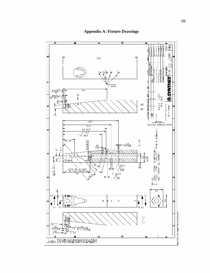
69
Appendix A: Fixture Drawings
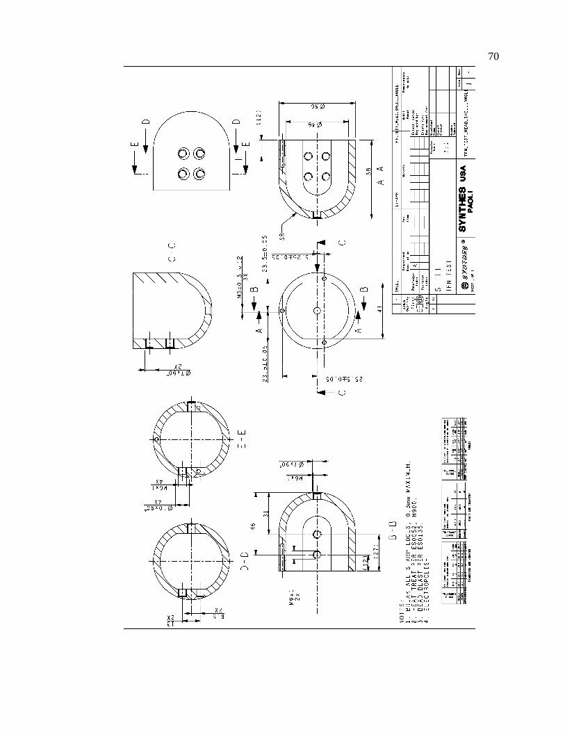
70
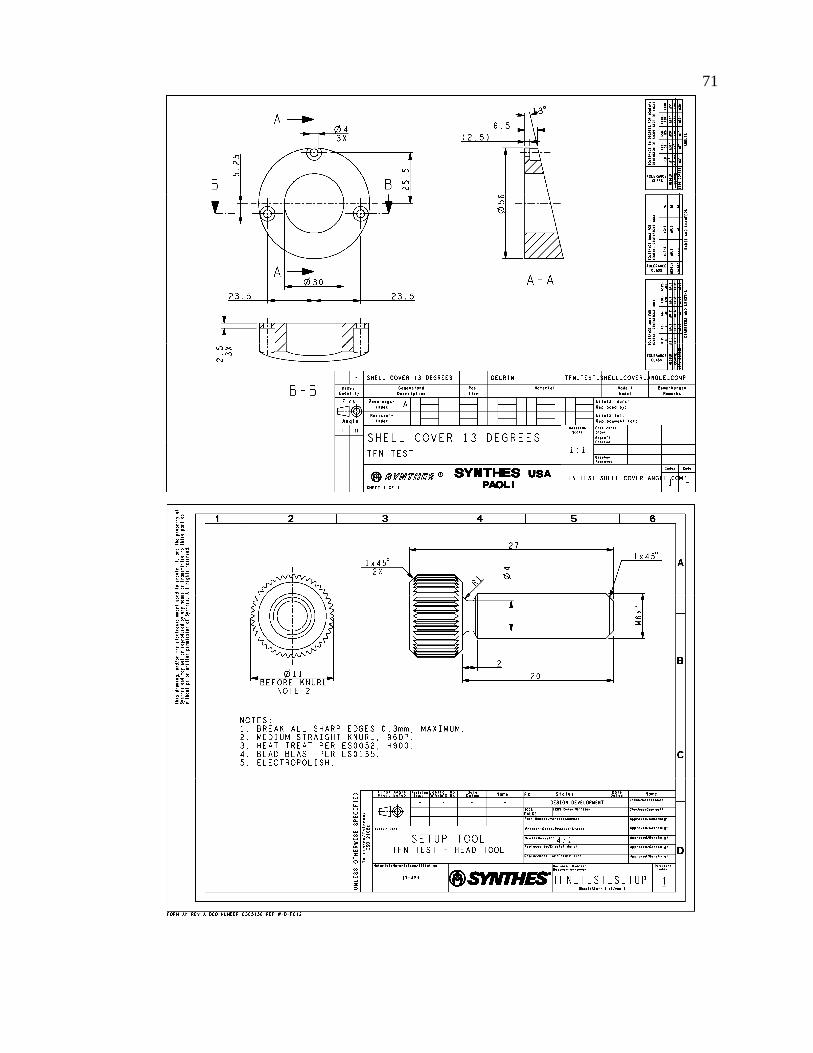
71
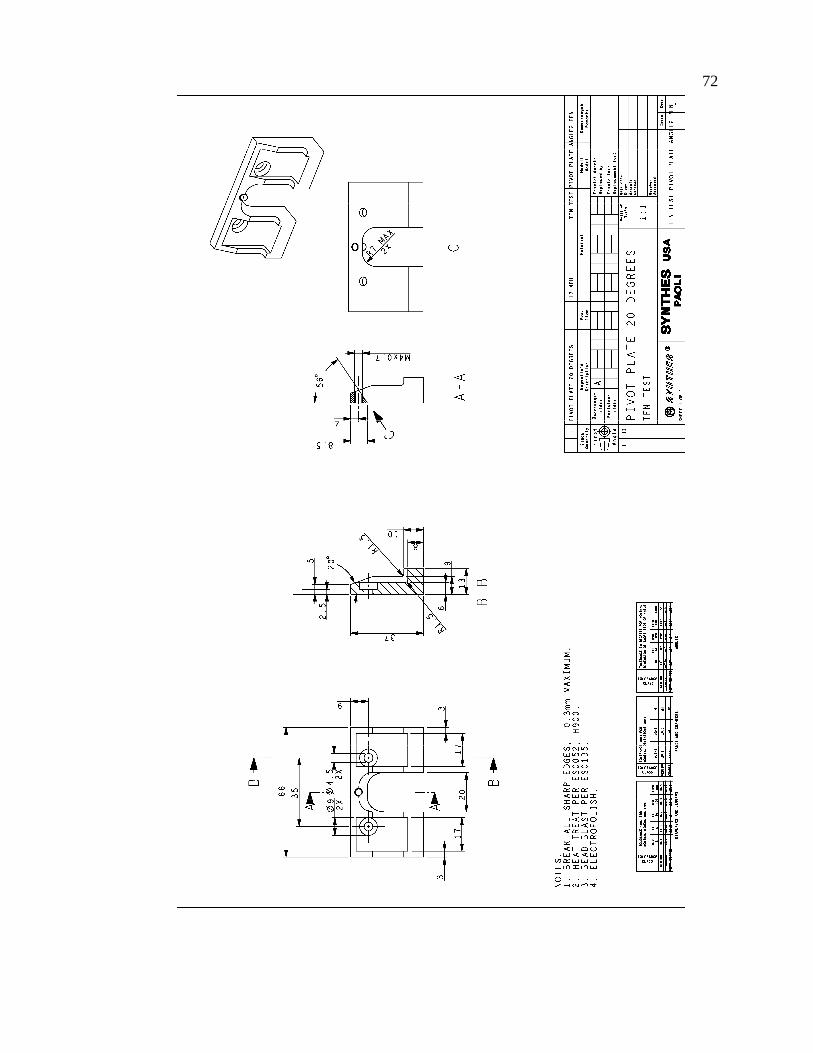
72

73

74

75
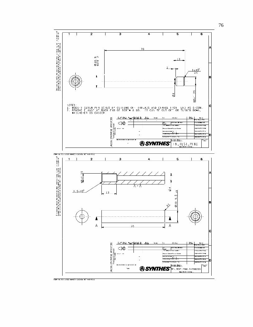
76

77

78

79

80

81

82