MECT411 Capstone Team Project Eastern Mediterranean...
131
Department of Mechanical Engineering, Eastern Mediterranean University MECT411 Capstone Team Project Eastern Mediterranean University Faculty of Engineering Department of Mechanical Engineering Ethernet Automated Pill Dispenser Course Coordinator Assist. Prof. Dr. Mostafa Ranjbar Supervisor: Assist. Prof. Dr. DAVUT SOLYALI Team Members Muammer Güzel 121776 Hakan Altıntaş 142327 Abdullah Yılmaz 120864 Group Name: I Don’t Know CAPSTONE TEAM PROJECT SPRING 2015-2016
Transcript of MECT411 Capstone Team Project Eastern Mediterranean...

Department of Mechanical Engineering, Eastern Mediterranean University
MECT411 Capstone Team Project
Eastern Mediterranean University
Faculty of Engineering
Department of Mechanical Engineering
Ethernet Automated Pill Dispenser
Course Coordinator
Assist. Prof. Dr. Mostafa Ranjbar
Supervisor:
Assist. Prof. Dr. DAVUT SOLYALI
Team Members
Muammer Güzel 121776
Hakan Altıntaş 142327
Abdullah Yılmaz 120864
Group Name: I Don’t Know
CAPSTONE TEAM PROJECT SPRING 2015-2016

Department of Mechanical Engineering, Eastern Mediterranean University
2
JURY MEMBERS
Name
Signature
Assoc. Prof. Dr. Hasan Hacışevki
Assist. Prof. Dr. Davut Solyalı
Lec. Cafer Kızılörs

Department of Mechanical Engineering, Eastern Mediterranean University
3
ABSTRACT
The automatic pill dispenser is increasingly becoming common in homes today because
of the way diseases multiply day by day. To avoid diseases, it is important to take medication
on time with the right dosage. Ethernet Automatic Pill Dispenser (e-APD) is specifically for
patients who take their pill (medicine) without get any help from caregiver or other. It
prevents the user from making the mistake of taking the wrong medicines at wrong time.
The main components of this pill dispenser are based on Arduino board as a
microcontroller with Ethernet shield interfaced with a computer using C# programming.
Arduino is controlling a LED flash light, an alarm system, motor controllers, water valves and
a multiple pill container (3 containers). Basically, in our project we will use a new system that
provides communication between the pill dispenser machine from the patient homes and
computers in the doctors’ offices which will allows the correct dose to be available at the
correct time with the help of real time clock module. We are mainly concerned with the inside
of the machine as a cylindrical system which consists of 3 separate containers that contain
different sizes and types of pills. There will be an arm placed in the centre of container system
and it will be picking the pill from inside of container to outside by using air vacuum. Current
sensor will be used to check if the arm took pill or not. Additionally, a glass of water is given
with the pill. The aim of this project is to design a medication dispenser system which gives
feedback such as how many pills left inside the machine, checks if the user takes the pill or
not. First of all doctors will program the machine like setting the time and how many times
the patient will the patients will take in a day or over specification period of time. After doctor
confirms the program, s/he send it into machine, the machine starts to work. Doctor can
connect to machine any time again by using security password. When the time is came for
the patient to use the pill, the correct container moves under the arm with help of the rotation
of the step motor. Then the arm moves into the container to pick a pill by air vacuum pump.
After picking a pill, at the same time water will be given and led display with alarm system
start to work. The user is required to press a button to reset the alarm. The major objective is
to keep the device simple, cost efficient and useful. The software used is reliable and stable.
Elderly population can benefit from this device as it is not expensive in-home medical care.

Department of Mechanical Engineering, Eastern Mediterranean University
4
Table of Contents ABSTRACT .........................................................................................................................3
CHAPTER 1 ....................................................................................................................... 10
INTRODUCTION .............................................................................................................. 10
1.1 What is the Pill Dispenser? ..................................................................................... 10
1.2 Advantages of the Pill Dispenser ............................................................................ 10
1.3 Disadvantages of the Market Pill Dispenser............................................................ 11
1.4 Functionality .......................................................................................................... 11
1.5 Scope of the work .................................................................................................. 11
1.6 Objective of the Project .......................................................................................... 12
1.7 Develop ability of pill dispenser ............................................................................. 12
1.8 Organization of the Report ..................................................................................... 12
CHAPTER 2 ....................................................................................................................... 14
LITERATURE REVIEW ................................................................................................... 14
2.1 Historical Background of Pill Dispenser ................................................................. 14
CHAPTER 3 ....................................................................................................................... 18
DESIGN AND ANALYSIS ................................................................................................ 18
3.1 Components of Ethernet Automatic Pill Dispenser Machine ................................... 18
3.1.1 Arduino Mega R3 Board ................................................................................. 19
3.1.2 Arduino Ethernet Shield ................................................................................. 19
3.1.3 DS3231 Real Time Clock Module .................................................................. 20
3.1.4 Step Motors .................................................................................................... 22
3.1.5 DC Micro Vacuum Pump ............................................................................... 23
3.1.6 C# Programming to Connect Arduino ............................................................. 24
3.2 Apply Engineering and Science to Select Suitable Materials .................................. 25
3.2.1 Material Selection for Material Design ........................................................... 25
3.2.2 Material Criteria and Goals ............................................................................. 25
3.2.3 Some Factors for Material Selection ............................................................... 26
3.2.4 Main factors for material selection .................................................................. 26

Department of Mechanical Engineering, Eastern Mediterranean University
5
3.3 Materials Used in the System ................................................................................. 27
3.3.1 Plexiglas (Polymathic Methacrylate)................................................................. 27
3.3.1.1 Why Plexiglas? ............................................................................................ 28
3.3.2 Stainless Steel................................................................................................... 28
3.3.3 Thermoplastic ................................................................................................... 29
3.3.4 Pneumatic Hose ................................................................................................ 29
3.4 Design Calculation ................................................................................................. 30
3.4.1 Calculation of Stepper Motor Step Angle ........................................................ 30
3.4.2 Calculation of Vacuum Holding Force in Carrying System ............................. 31
3.4.3 Water Discharge from Water Storage .............................................................. 33
3.5 Cost Analysis of Project ......................................................................................... 34
CHAPTER 4 ....................................................................................................................... 35
MANUFACTURING, ASSEMBLY AND TESTING......................................................... 35
4.1 The Pill Holder Mechanism (PHM) ........................................................................ 36
4.1.1 Manufacturing of the PHM ............................................................................. 36
4.1.2 Assembly of the PHM..................................................................................... 41
4.2 The Pill Container Mechanism (PCM).................................................................... 41
4.2.1 Manufacturing of the PCM ............................................................................. 42
4.2.2 Assembly of the PCM ..................................................................................... 43
4.3 Testing of PCM and PHM ...................................................................................... 44
4.4 Ironmongery Engineering Standard for Assembly .................................................. 45
4.4.1 Nut-Bolt ........................................................................................................ 45
4.4.2 Steel Threaded Rod ........................................................................................ 45
4.4.3 Setsquare Bolt................................................................................................. 45
CHAPTER 5 ....................................................................................................................... 47
RESULT AND DISCUSSION............................................................................................ 47
CHAPTER 6 ....................................................................................................................... 48
CONCLUSION AND FUTURE WORK ............................................................................ 48
6.1 Conclusion ............................................................................................................. 48
6.1.1 Software Design ............................................................................................. 48
Department of Mechanical Engineering, Eastern Mediterranean University
6
6.1.1.1 Username and Password Control ............................................................ 48
6.1.1.2 File Option ............................................................................................. 54
6.1.1.3 Edit Option ............................................................................................ 54
6.1.1.4 Tools Option .......................................................................................... 55
6.1.1.5 Help Option ........................................................................................... 56
6.2 Future Works ..................................................................................................... 56
REFERENCES ................................................................................................................... 58
APPENDICES .................................................................................................................... 60
APPENDIX A .................................................................................................................... 61
LOGBOOKS ...................................................................................................................... 61
APPENDIX B .................................................................................................................... 72
GANTT CHART ................................................................................................................ 72
APPENDIX C .................................................................................................................... 75
DRAWING ........................................................................................................................ 75
APPENDIX D .................................................................................................................. 109
APPENDIX E ................................................................................................................... 129
Poster: ................................................................................................................... 130
Department of Mechanical Engineering, Eastern Mediterranean University
7
List of Figures
Figure 1.1 Pill Dispenser [1] ............................................................................................................... 10
Figure 2.1 Shapes of Pills [6] .............................................................................................................. 15
Figure 3. 1 Organization chart of Pill Dispenser ................................................................................. 18
Figure 3. 2 An Arduino Mega R3 Board .............................................................................................. 19
Figure 3. 3 An Ethernet shield for Arduino Mega ............................................................................... 20
Figure 3. 4 Real time Clock Module ................................................................................................... 21
Figure 3. 5 Step Motor [10] ............................................................................................................... 23
Figure 3. 6 A DC Micro Vacuum Pump [11] ........................................................................................ 24
Figure 3. 7 Interface of C# Programming ........................................................................................... 24
Figure 3. 8 Plexiglas [13].................................................................................................................... 28
Figure 3. 9 Stainless Steel Sheet Metals [15] ..................................................................................... 28
Figure 3. 10 Thermoplastic [18] ......................................................................................................... 29
Figure 3. 11 Pneumatic Hose [19] ...................................................................................................... 29
Figure 3. 12 Vertical Force -1 ............................................................................................................ 31
Figure 3. 13 Vertical and Horizontal Force ........................................................................................ 32
Figure 3. 14 Vertical Force -2 ............................................................................................................. 32
Figure 3. 15 Water Tank .................................................................................................................... 33
Figure 4. 1 General View of Ethernet Automatic Pill Dispenser (e-APD) ............................................. 35
Figure 4. 2 General View of the Pill Holder Mechanism ..................................................................... 36
Figure 4. 3 SolidWorks Drawing for CNC Machine-1. ......................................................................... 37
Figure 4. 4 Processing of Thermoplastic Material with Using CNC Machine. ...................................... 37
Figure 4. 5 Vacuum Aluminium Pie Holder Parts ................................................................................ 37
Figure 4. 6 Bearing Beds Parts (upper and lower) .............................................................................. 38
Figure 4. 7 Connection Part between Vacuum Aluminium Pie Holder and Gear Shaft. ....................... 38
Figure 4. 8 SolidWorks Drawing for CNC Machine-2. ......................................................................... 39
Figure 4. 9 Bearing Beds Support Parts (upper and lower) ................................................................. 39
Figure 4. 10 Stepper Motor Support Part and T Part to fix Vacuum Pie Holder Part. .......................... 39
Figure 4. 11 M8 Gear Shaft ............................................................................................................... 40
Figure 4. 12 M6 Support Rods ........................................................................................................... 40
Figure 4. 13 Turning Machine is machining........................................................................................ 40
Figure 4. 14 General view of the Pill Container Mechanism ............................................................... 41
Figure 4. 15 Bearing Bed Part Lower.................................................................................................. 42
Figure 4. 16 Steel Rod Machining in Lathe ......................................................................................... 42
Figure 4. 17 Laser cutting machine .................................................................................................... 43
Figure 4. 18 Joint .............................................................................................................................. 44
Figure 4. 19 Beech wood ................................................................................................................... 44
Figure 4. 20 Part of Name Nut and Bolt [20] ...................................................................................... 45
Figure 4. 21 Steel Threaded Rod [22] ................................................................................................ 45
Figure 4. 22 Setsquare Bolt [23] ....................................................................................................... 46
Figure 6. 1 Username and Password Control ..................................................................................... 49
Figure 6. 2 Wrong Username and Password Control .......................................................................... 49
Figure 6. 3 Warning When More than Three Times Entering Wrong Information .............................. 50
Figure 6. 4 Saving LOGIN Information to Database ............................................................................ 50
Figure 6. 5 Main Menu ...................................................................................................................... 51
Department of Mechanical Engineering, Eastern Mediterranean University
8
Figure 6. 6 Searching Existing Patient by ID ....................................................................................... 51
Figure 6. 7 Update Patient Information ............................................................................................. 52
Figure 6. 8 Machine Connection ........................................................................................................ 52
Figure 6. 9 Machine Settings ............................................................................................................. 53
Figure 6. 10 Selecting to the Taking to Medicine Time ....................................................................... 53
Figure 6. 11 File Menu and Exiting from the Program ........................................................................ 54
Figure 6. 12 Edit Doctor Information ................................................................................................. 54
Figure 6. 13 Edit Doctor Information ................................................................................................. 55
Figure 6. 14 Changing the password 1 ............................................................................................... 55
Figure 6. 15 Changing the password 2 ............................................................................................... 55
Figure 6. 16 Contact us...................................................................................................................... 56
Figure 6. 17 About Automated Pill Dispenser .................................................................................... 56

Department of Mechanical Engineering, Eastern Mediterranean University
9
List of Tables
Table 1 :Six Studies Automated Drug Dispensing Systems [8] ............................................................ 16
Table 2: Step Motor Properties [10] .................................................................................................. 22
Table 3: Vacuum Pump Properties [11] ............................................................................................. 23
Table 4: Cost Analysis of Project ........................................................................................................ 34

Department of Mechanical Engineering, Eastern Mediterranean University
10
CHAPTER 1
INTRODUCTION
1.1 What is the Pill Dispenser?
The pill dispensers in the other words electronic pill organisers are developed to alert
people about their medication. It is an easy way to use tablet dispenser which can assist in the
management of medication and allows the correct dose to be available at the correct time of
day or night. Their purpose is to help people who may suffer from impaired ability to adhere
to their prescribed medication regime.
They are commonly used in medicine and some people can use individually as well
such as elderly, chronically ills. These devices are evolved to care public health, the cost of
medicine industry and waste of drugs. The advanced models of these dispensers can be
available in the medicinal industry.
1.2 Advantages of the Pill Dispenser
Pill dispenser provides lots of benefits for us. First of all, this project will be useful for
people who forget to take their medicine on time. Secondly, people who have many medicines
to take and confused about which medicine at which time. So this project will help people to
prevent from taking wrong medicines at wrong times thus this will be beneficial for healing.
Figure 1.1 Pill Dispenser [1]

Department of Mechanical Engineering, Eastern Mediterranean University
11
1.3 Disadvantages of the Market Pill Dispenser
In the market, there are a few kinds of pill dispensers (See Appendix D) which are
quite useful. Although these pill dispensers are useful, they need to be developed because of
some lack of properties such as,
They cannot be controlled remotely by doctor or expert
Pills must be filled by hand one by one inside the cup
Capacity is limited such as weekly or monthly
Different pills must be in the same cup during the period of taking pills
They haven’t water storage to swallow pill
They used by patient or someone so that patient might take the wrong pill
They are quite expensive
They don’t suit all patient such as illiterate, weak-sighted and not having a person
or relative to help
In our project, we will try to resolve these problems and try to make it better.
1.4 Functionality
When the time comes to take medicine, the machine will releases pills into a small cup
and it gives a sounding signal and flashing led which mean that it is time to take the
medicines. If the user doesn’t take the cup which contains drugs then the machine will inform
the doctor after a pre-considered time.
1.5 Scope of the work We will design and manufacturing such a machine which will be used by doctor to
control the amount of taking pill for patient for instance uneducated, elderly, physically
disabled, forgetful people etc. This machine will have 3 different and independent pill tubes
from each other. Doctor who is giving the medicine will control and adjust the machine from
the internet like how many times patients will get in a day and which one will take? There
will be software to communicate with machine, useable interface, three step/servo motors
inside the machine and mechanical connection parts. This machine will be based on Arduino.
On the taking of pill time, the machine will warn patient as warning tone. There will be a
counter for the count how many pill is taking by patient and how many is left inside the
machine. For the security of using machine, doctor will have a password to enter the system
otherwise, someone who is from outside won’t enter the system. Also this machine gives the
one glass of water with pill to shallow.

Department of Mechanical Engineering, Eastern Mediterranean University
12
1.6 Objective of the Project
Nowadays, the drug consumption increased with the increase of health problems and
also waste of medicines has an important role on public health. However, the waste of drugs
has huge cost for the world. If we consider just UK, unused prescription medicines cost over
£300 million every year [2]. That situation may have many reasons.
One of these reasons is, people don’t use medicines carefully, on the time. Maybe they
can forget to take them, or elder people may have so many types of medicines that they can
get confused and don’t remember to take them on time.
The aim of this project, help to people who are elderly and always forget to take their
pills on the time. This project is going to help them and make their life easier.
On the other hand, the cost is inexpensive and to get this machine will be
economically easy. Consequently, we wanted to create such as machine which will be in
every elderly people’s home.
1.7 Develop ability of pill dispenser
Pill dispensers are already used in these days. In this project we developed as much as
possible using today’s technology. But it doesn’t mean that that it is the final version of pill
dispensers. In the future it may have connection with human using smart clocks, can measure
blood pressure, heart beat changes for these patients. And for these emergency situations it
can inform the patient to take drug urgently and prepare the dosages or tablets. Injection
forms of this dispenser also can be developed by scientists.
Consequently the pill dispensers can be developed by the time and new forms of
dispensers seems possible with the technology.
1.8 Organization of the Report
In chapter 1, the introduction is written and the pill dispenser need is discussed with
variety of the pill dispenser processes .In Chapter 2 literate review of the pill dispenser
process is discussed with reviewing previous works on the pill dispenser process while in

Department of Mechanical Engineering, Eastern Mediterranean University
13
Chapter 3 design and analysis is discussed where design of the automatic pill dispenser is
provided and explaining of the components involved in the machine. In Chapter 4,
manufacturing, assembly and testing processing are explained. The Chapter 5 has result and
discussion and the last chapter which is six and has conclusion with software and future work.
The report also includes the Appendices as, Appendix-A Log books, Appendix-B Gantt chart,
Appendix-C Drawing, Appendix-D Engineering Standards and Appendix-E Poster website of
project and CD.

Department of Mechanical Engineering, Eastern Mediterranean University
14
CHAPTER 2
LITERATURE REVIEW
2.1 Historical Background of Pill Dispenser
In this chapter, it will summarize respectively development of pill, making pill
machine, shape of pill and development of pill dispenser with their efficiency.
The invention of the pill date is back to roughly 1500 BC as a liquid from. This date
refers ancient Egyptian times and according to researches many recipes are found from
ancient Egyptian living areas. After that, development of pill continued in ancient Greece
because Roman scholar Pliny has found katapotia (meaning "something to be swallowed")
and he lived from 23-79 AD. Also Roman’s pill-making equipment is being on display in the
British Museum. In 17th century England and thereafter, pill manufactures were granted
special patent rights from the king. Then the compressed tablet was invented in the 1800s by a
Brit named William Brockedon. He put powder in a tube and compressed it with a mallet, and
thus a whole new type of pill was created [3]. After these developments, patient people have
begun to choose this kind of treatment because this method has some advantages such as
calibration of dose easily and pill is suitable to treatment a wide variety of diseases so that
manufacturing of pill industry have begun to grow rapidly. A well-known fact that all,
industries need a machine or machines to produce their products. Because of this reason,
pharmaceutical manufacturers developed some devices to produce their pill. In 1867’s August
H. Wiez developed the first patented pill making machine [4]. (Appendix D). Most important
development of making pill machines was in between interwar 1918 to 1939 so that many
factories has been establish around the world to produce many types of pills[5].
After these developments, taking of pill has spread around the world and pill industry
has evolved accordingly. At the same time, some problems began to appear. First problem is
swallowing of pill because difficulty swallowing tablets and capsules can be a problem for
many individuals and can lead to a variety of events and can show negative effect on the
patient with treatment method. Then manufacturers have created many different types of pill.
(Figure. 2.1)

Department of Mechanical Engineering, Eastern Mediterranean University
15
Figure 2.1 Shapes of Pills [6]
Second problem is taking of pill on the right time so that manufacturers have put pills
inside special packed to remove them by one by with hand and take on the time but it could be
useless for some patients. Therefore, in 1964, David P. Wagner has invented the first patent
pill dispenser to control oral contraceptive pills of his wife [7]. (Appendix D).
Significant development of pill dispenser has started to appear ın 1980s because of
technological developments which have affected all devices because old devices were not
enough to make life easier. Therefore, In the 1980s, automated dispensing devices appeared
on the pill market. The invention and production of these devices brought hopes of reduced
rates of medication errors, increased efficiency for pharmacy and nursing staff, ready
availability of medications. The capacity of such systems increased patient safety and
provided to control amount of taking pill on time. Efficiency of this system is seen in Table 1.

Department of Mechanical Engineering, Eastern Mediterranean University
16
Table 1 :Six Studies Automated Drug Dispensing Systems [8]
Study Study Design Study Outcomes Results
Barker, et al 1984
Prospective controlled clinical
trial (Level 2)
Errors of omission and
commission among number of ordered and
unauthorized doses. (Level 2)
96 errors among 902 observations (10.6%) using the McLaughlin dispensing system vs. 139 errors
among 873 observations (15.9%) using unit-dose dispensing (control)
Klein, et al 1994
Prospective
comparison of two cohorts (Level 2)
Dispensing errors in unit-dose drawers to be
delivered to nursing units (Level 2)
34 errors found among 4029 doses (0.84%) filled manually by technicians vs. 25 errors among 3813
doses (0.66%) filled by automated dispensing device
Borel, et al 1995
Prospective before-
after study (Level 2)
Errors observed during medication
administration in medications
administered (Level 2)
148 errors among 873 observations (16.9%) before vs. 97 errors among 929 observations (10.4%) after Meditation Rx (p<0.001). Most errors were wrong
time errors.
Schwarz, et al
1995
Prospective before-after study (Level
2)
Errors in medications
administered (Level 2)
Medication errors decreased after automated dispensing on the cardiovascular surgery unit but
increased on the cardiovascular intensive care unit.
Dean, et al 1995
Cross-sectional comparison (Level 3) of US and UK
hospitals with
different pharmacy distribution systems
Errors in medications administered (Level 2)
63 errors among 919 observations (6.9%, 95% CI: 5.2-8.5%) in the US hospital using unit doses and automated dispensing vs. 84 errors among 2756
observations (3.0%; 95% CI, 2.4-3.7%) in the UK
hospital using ward stock. The absolute difference in error rates was 3.9% (95%CI: 2.1-5.7%).
Explanation of table 1, Level 2 outcome is to all studies measured rates of medication
errors and Level 3 design is to determined errors by inspecting dispensed drugs. The Pyxis
Medstation, Medstation Rx, and Medstation Rx 1000 are automated dispensing devices kept
on the nursing unit. The Baxter ATC-212 dispensing system uses a microcomputer to pack
unit-dose tablets and capsules for oral administration. The McLaughlin dispensing
system includes a bedside dispenser, a programmable magnetic card, and a pharmacy
computer.
The results of the study of the McLaughlin Dispensing System by Barker et al showed
considerable nurse-to-nurse variability in the error rate. This error is between the automated
system and usual unit dose.
The study by Klein et al showed little difference in the correctness of medication cart
filling by the Baxter ATC-212 (0.65%) as opposed to filling by technicians (0.84%).

Department of Mechanical Engineering, Eastern Mediterranean University
17
Borel and Rascati found that medication errors, mostly those related to the time of
management, were fewer after application of the Pyxis Medstation Rx (10.4%) compared with
the historical period (16.9%).
In the study by Schwarz, errors were greater after Medstation Rx and Brodowy,
increasing on 6 of 7 nursing units by more than 30%.
Dean et al found half the errors in a ward-based system without automation in the
United Kingdom (3.0%, 95% CI: 2.4-3.7%) compared with an automated unit-dose
medication distribution system in the United States (6.9%, 95% CI: 5.2-8.5%).
To sum up, at the beginning, pill dispenser processes was just a packaging to conserve
and take pill one by one. After that amount of taking different types of pill was increased in
this way pill firms invented pill dispenser boxes but these boxes are not useful nowadays for
all patient people. Therefore, new pill dispensers have started to appear on the market with the
development of technology. The most widely used pill dispensers on the market is seen in
Appendix D with their properties. In addition, before starting our project we investigated
market pill dispensers and we found many disadvantages which are mentioned in Chapter 1 so
that in the next chapter, we will design the project considering the disadvantages.
Department of Mechanical Engineering, Eastern Mediterranean University
18
CHAPTER 3
DESIGN AND ANALYSIS
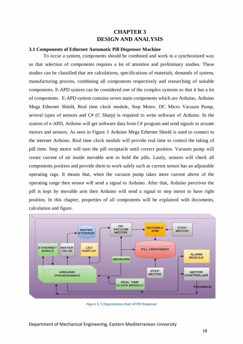
3.1 Components of Ethernet Automatic Pill Dispenser Machine
To occur a system, components should be combined and work in a synchronized way
so that selection of components requires a lot of attention and preliminary studies. These
studies can be classified that are calculations, specifications of materials, demands of system,
manufacturing process, combining all components respectively and researching of suitable
components. E-APD system can be considered one of the complex systems so that it has a lot
of components. E-APD system contains seven main components which are Arduino, Arduino
Mega Ethernet Shield, Real time clock module, Step Motor, DC Micro Vacuum Pump,
several types of sensors and C# (C Sharp) is required to write software of Arduino. In the
system of e-APD, Arduino will get software data from C# program and send signals to actuate
motors and sensors. As seen in Figure 3 Arduino Mega Ethernet Shield is used to connect to
the internet Arduino. Real time clock module will provide real time to control the taking of
pill time. Step motor will turn the pill receptacle until correct position. Vacuum pump will
create current of air inside movable arm to hold the pills. Lastly, sensors will check all
components position and provide them to work safely such as current sensor has an adjustable
operating rage. It means that, when the vacuum pump takes more current above of the
operating range then sensor will send a signal to Arduino. After that, Arduino perceives the
pill is kept by movable arm then Arduino will send a signal to step motor to have right
position. In this chapter, properties of all components will be explained with documents,
calculation and figure.
Figure 3. 1 Organization chart of Pill Dispenser

Department of Mechanical Engineering, Eastern Mediterranean University
19
3.1.1 Arduino Mega R3 Board
Arduino is an open source microcontroller board and it’s based on easy to use software
and hardware. Arduino boards can used to read sensors and control anything like motors and
lights. It has a big advantage which it is possible to upload programs to the Arduino board as
shown in Figure 3.2 which communicate between real world and computers. In our project, it
will be useful board because of it will connect computer to machine by sending a set of
instructions to the Arduino (See Appendix D). Essentially, Arduino can deal with something
that is controlled with electricity. An easy way to interface with does not controlled by the
electricity, by using actuators.
Figure 3. 2 An Arduino Mega R3 Board
3.1.2 Arduino Ethernet Shield
The Arduino Ethernet Shield connects your Arduino to the internet which is based on
the Wiznet W5100 (datasheet) Ethernet chip. Just plug Ethernet module onto Arduino board
and connect it to network with RJ45 cable. The Wiznet W5100 Ethernet chip serves a
network (IP) stack capable of TCP and UDP. It’s simple to using the datasheet, by sending a
set of instructions to start controlling to the Arduino from the internet. The Ethernet shield
provides its power from the Arduino and there is a micro SD card slot on the shield as shown
in Figure 3.3 which can be used to store files. Also the shield contains some
informational LEDs as follow;

Department of Mechanical Engineering, Eastern Mediterranean University
20
PWR: indicates that the board and shield are powered
LINK: indicates the presence of a network link and flashes when the shield transmits or
receives data”
FULLD: indicates that the network connection is full duplex
100M: indicates the presence of a 100 Mb/s network connection (as opposed to 10 Mb/s)
RX: flashes when the shield receives data
TX: flashes when the shield sends data
COLL: flashes when network collisions are detected
Figure 3. 3 An Ethernet shield for Arduino Mega
3.1.3 DS3231 Real Time Clock Module
DS3231 is a minimal effort, highly accurate I2C Real-Time Clock (RTC), with a
combined temperature-compensated crystal oscillator (TCXO) and crystal in seen Figure 6.
The module has a battery on it which is used for when the main power failure, the device can
continue to provide accurate timing. So performance is not affected. That’s why we will use
the RTC because of it is only solution for e-APD machine to prevents to power supply failure
and improves accuracy of timing. Crystal oscillator is used for long-term accuracy of the
device and reduces the number of components. RTC contains seconds, minutes, hours, day,
date, month, and year information. If month is less than 31 days, the end date will be
automatically adjusted, including corrections for leap year. It is possible to use the device as
24 hours or 12-hour format. Some important module parameters are given below.

Department of Mechanical Engineering, Eastern Mediterranean University
21
Module parameters:
Operating voltage :3.3 - 5 .5 V
Clock Accuracy: 0-40 ℃ range, the accuracy 2ppm, the error was about 1 minute calendar
alarm clock with two programmable square-wave output
Real time clock generator seconds, minutes, hours, day, date, month and year timing and
provide valid until the year 2100 leap year compensation
with rechargeable battery LIR2032, to ensure the system after power failure, the clock
move any natural normal
Arduino connection information:
SCL → Arduino
SDA → Arduino
VCC → 5V
GND → GND
Figure 3. 4 Real time Clock Module

Department of Mechanical Engineering, Eastern Mediterranean University
22
3.1.4 Step Motors
A stepper motor system (See Appendix D) consists of three basic elements, often
combined with some type of user interface (host computer, PLC or dumb terminal):
Controller: (Indexer) is a microprocessor capable of generating step pulses and direction
signals for the driver [9].
Drivers: The driver (or amplifier) converts the indexer command signals into the power
necessary to energize the motor windings. There are numerous types of drivers, with
different voltage and current ratings and construction technology. Not all drivers are
suitable to run all motors, so when designing a motion control system the driver selection
process is critical [9].
Stepper motors: The stepper motor is an electromagnetic device that converts digital
pulses into mechanical shaft rotation in shown Figure 3.5 . Advantages of step motors are
low cost, high reliability, high torque at low speeds and a simple, rugged construction that
operates in almost any environment. The main disadvantages in using a stepper motor is
the Resonance effect often exhibited at low speeds and decreasing torque with increasing
speed [9].
Table 2: Step Motor Properties [10]
Rated Voltage 12VDC
Number of Pole 4
Stride Angle 7.5°
Drive Mode 2-2 Single Pole
DC Resistance 4Ω/phase±10%(25℃)
Current 400mA
Max Start Frequency ≥650PPS
Max Idle Out-traction Frequency ≥1600PPS
In-traction Torque ≥100gf.cm(200PPS)
Self-positioning Torque ≤100gf.cmREF
Induction Resistance 3.5H/Phase±10%(1KHz 1Vrms)
Insulation Grade A
Department of Mechanical Engineering, Eastern Mediterranean University
23
Figure 3. 5 Step Motor [10]
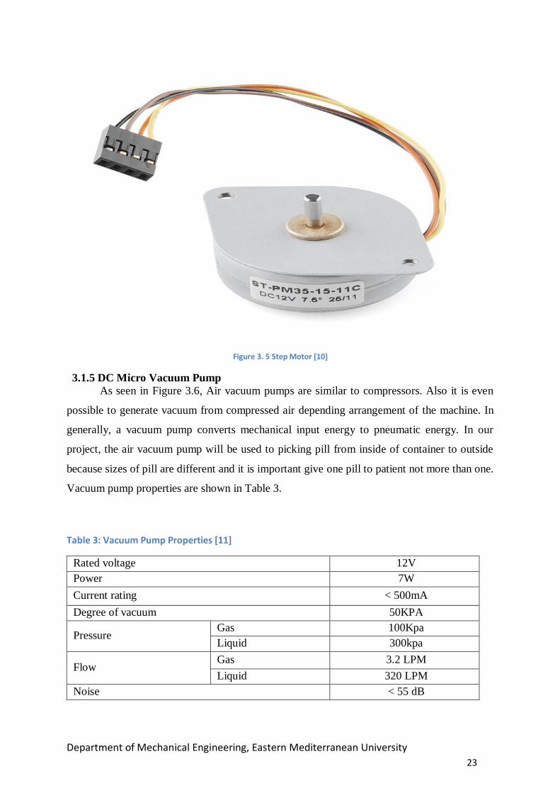
3.1.5 DC Micro Vacuum Pump
As seen in Figure 3.6, Air vacuum pumps are similar to compressors. Also it is even
possible to generate vacuum from compressed air depending arrangement of the machine. In
generally, a vacuum pump converts mechanical input energy to pneumatic energy. In our
project, the air vacuum pump will be used to picking pill from inside of container to outside
because sizes of pill are different and it is important give one pill to patient not more than one.
Vacuum pump properties are shown in Table 3.
Table 3: Vacuum Pump Properties [11]
Rated voltage 12V
Power 7W
Current rating < 500mA
Degree of vacuum 50KPA
Pressure Gas 100Kpa
Liquid 300kpa
Flow Gas 3.2 LPM
Liquid 320 LPM
Noise < 55 dB

Department of Mechanical Engineering, Eastern Mediterranean University
24
Figure 3. 6 A DC Micro Vacuum Pump [11]
3.1.6 C# Programming to Connect Arduino
Ethernet Shield is used for communication between the e- APD machine (Arduino
board) and a computer. Also all Arduino boards have one serial port (also known as a UART
or USART). It communicates on digital pins 0 (RX) and 1 (TX) as well as with the computer
via USB. Thus, Ethernet shield use these RX and TX, also it is not allowed to use pins 0 and 1
for digital input or output. In this Project, C# (C Sharp) will be used to communicate with an
Arduino board as an interface program between Arduino and computer as shown in Figure 3.7
Figure 3. 7 Interface of C# Programming

Department of Mechanical Engineering, Eastern Mediterranean University
25
3.2 Apply Engineering and Science to Select Suitable Materials
3.2.1 Material Selection for Material Design
In any project is designed by engineer, selection of materials must be impeccable so
that selection principles should be consider. The selections principles can be classified such as
machinability, cost of material, weight of material in unit cube, durability and mechanical
performance data is also most significant which is obtainable with observation of other
designed project. Also, these principles can help designer to increase efficiency of machine,
decrease weight and cost of project and provide long life under the environmental effects.
Environmental effects are different all over the world and under working condition so that it
also must be investigated from the designer. In addition, designer also has to consider material
properties under two principles which are general properties of the mechanical and electrical
to prevent oxidation and check suitability each other. These properties are listed below.
Density
Strength
Elasticity
Ductility
Hardness
Conductivity
Insulation
Designers should take into account the characteristics of the material while selection
of materials. For example, each material has different density from each other so that
materials light and stiff are different. Also composite and alloy material can be more useful
instead of pure material because composite and alloy material are designed based on request.
In addition, electrical properties should be considered by the designer because if the designer
uses conductive material instead of insulator material there will be electrical risk and shock
for project and machine user.
3.2.2 Material Criteria and Goals
All materials have a durability limit under working condition therefore the designer
have to consider the limitation of materials. The limitation of material depends on material
criteria such as vibration, strength and heat resistance. Another criterion is cost limitation that

Department of Mechanical Engineering, Eastern Mediterranean University
26
is most significant for designer. Therefore designer should select suitable and correct material
to control cost of project. In addition, design principles can be categorized as goals and
restrictions. For instance, designed project must be suitable mass and size and not waste
energy. Restriction can be about cost of material so that before the design project cost of
materials should research by designer.
3.2.3 Some Factors for Material Selection
Material selection is also depended some factors. These are during the manufacturing
period material must take appropriated form and can be designed. Sometimes very nice design
is not enough itself so that an engineer should focus on product colour, aesthetic appearance
and decoration to sell the many products. Therefore when the engineer chooses the materials,
should be careful, see all possibilities and have an open mind. In the selection of material, to
analyse factors some method can be used by engineer to selection that these are shown below.
Examination of the necessary properties of materials.
The selection of appropriate materials and apply some experiment and research
than select suitable one.
Developments of appropriate materials.
3.2.4 Main factors for material selection
Strength: The strength of a material is its ability to withstand an applied load
without failure or plastic deformation.
Ductility: It is ability of a material to deform easily over the application of
tensile force and ability of a material to withstand plastic deformation without rupture.
Design: In engineering design process, design depends on systematic steps that
engineers use convenient materials in processes. Engineering design process describes the
following stages: research, applicability assessment, establishing design requirements,
preliminary design, detailed design, production planning and tool design, and production.
Stability: It is a property of system. It means existence at rest, not responsible
to change. In mechanics and dynamics, a system has stability if it will not change motion of
its own accord, and will resist small efforts to change its direction or position.

Department of Mechanical Engineering, Eastern Mediterranean University
27
Availability: Availability is a characteristic of a system, which aims to provide
a decided level of operating performance. Also, availability has three main principles
of system design in availability engineering:
1. Elimination of single points of failure.
2. Reliable crossover.
3. Detection of failures as they occur.
Production Compliance: An engineer cannot apply some method into
materials to produce and give shape. Because of these reasons, Producer has to select suitable
method to get accurate shape from material. Examples of applicable methods are forming,
joining, turning, casting, bending, thermal processing etc.
Corrosion Resistance: Environmental conditions always effects material and
this effect decrease material working life thus to have long and enough working life from
material engineer should research corrosion resistance of material. Other ways to increase
corrosion resistance of materials, lubrication, painting and protection from sunlight.
Cost: Cost must be analysed by designer but price of material is not enough to
select material because after selection, material will to be processed by producer. The process
type can be increase cost of project.
3.3 Materials Used in the System
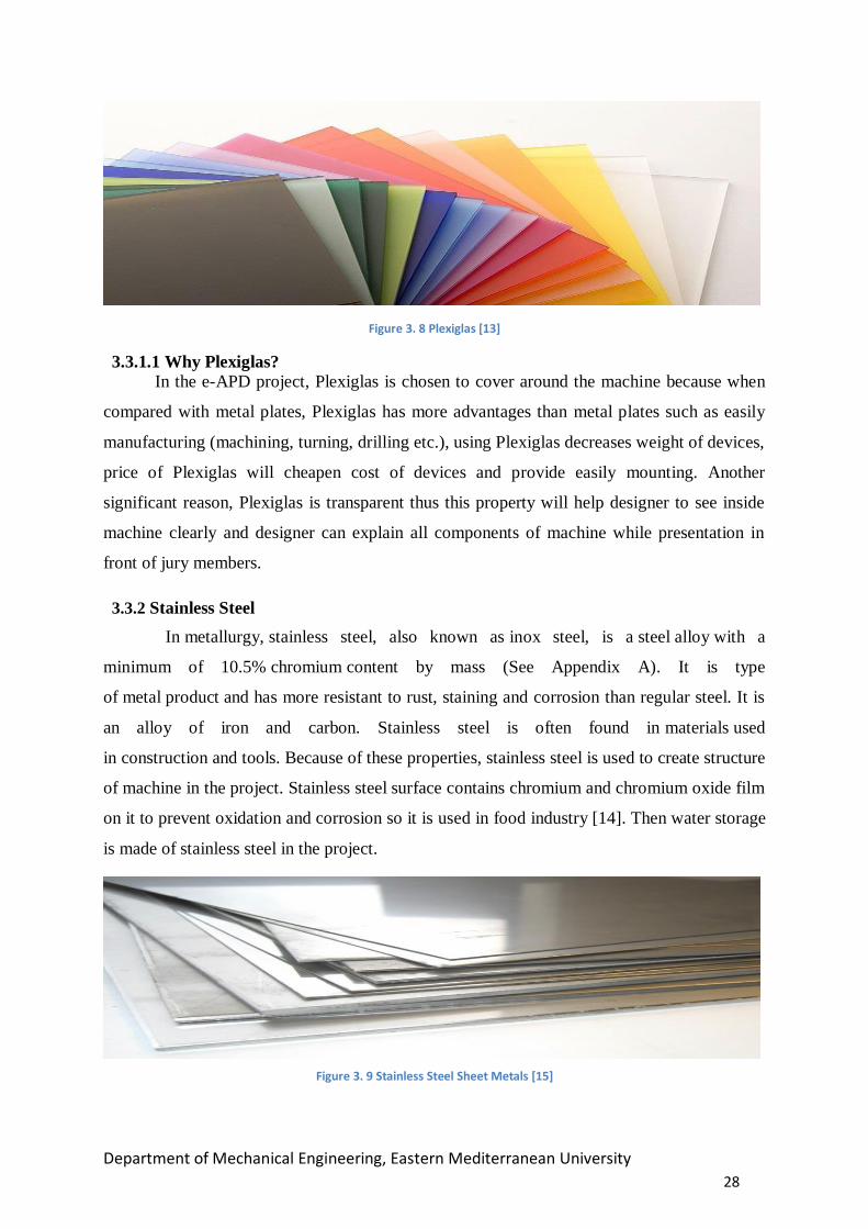
3.3.1 Plexiglas (Polymathic Methacrylate)
Plexiglas is a plastic glass which has coloured and colourless varieties. It can be
transparent and semi-transparent. It is easily processed and has a light plastic structure so can
be cut and drill easily. It is generally sold as 1.5-2 mm flat sheets on the market. It can be
softened by heating between 90°C – 115°C in the oven and it safe its shape after cooling thus;
it can be given the desired shape by moulding. It is more durable and lighter than glass. The
only disadvantage is it is a thermodynamic structure so it has low resistance to heat. Plexiglas
does not leave users in the lurch during manufacturing and does not create problem like sheet
extruders in the process of blow moulding and shaping. Its technical characteristics
(expansion coefficient, density, softening point in see appendix A) are appropriate in standard
and the number of polymer is high. Also it has high corrosion resistance under environmental
condition [12].
Department of Mechanical Engineering, Eastern Mediterranean University
28
Figure 3. 8 Plexiglas [13]
3.3.1.1 Why Plexiglas?
In the e-APD project, Plexiglas is chosen to cover around the machine because when
compared with metal plates, Plexiglas has more advantages than metal plates such as easily
manufacturing (machining, turning, drilling etc.), using Plexiglas decreases weight of devices,
price of Plexiglas will cheapen cost of devices and provide easily mounting. Another
significant reason, Plexiglas is transparent thus this property will help designer to see inside
machine clearly and designer can explain all components of machine while presentation in
front of jury members.
3.3.2 Stainless Steel
In metallurgy, stainless steel, also known as inox steel, is a steel alloy with a
minimum of 10.5% chromium content by mass (See Appendix A). It is type
of metal product and has more resistant to rust, staining and corrosion than regular steel. It is
an alloy of iron and carbon. Stainless steel is often found in materials used
in construction and tools. Because of these properties, stainless steel is used to create structure
of machine in the project. Stainless steel surface contains chromium and chromium oxide film
on it to prevent oxidation and corrosion so it is used in food industry [14]. Then water storage
is made of stainless steel in the project.
Figure 3. 9 Stainless Steel Sheet Metals [15]

Department of Mechanical Engineering, Eastern Mediterranean University
29
3.3.3 Thermoplastic
Thermoplastics are in plastic group that when heated thermoplastic it become soft,
again when cooled thermoplastic it become hard (See Appendix D). Thermoplastics have a
high molecular weight. Thus, thermoplastics may be reshaped by heating and are typically
used to produce parts by various polymer processing techniques such as injection moulding,
compression moulding, easy machining, and extrusion. In e-APD project, there are two
complex shapes which are pill containers and receptacle to carry pill containers [16-17].
Figure 3. 10 Thermoplastic [18]
3.3.4 Pneumatic Hose
It is usually used pneumatic system to propel cylindrical containers through networks
of tubes by compressed air or by partial vacuum. It is very durable to water, mineral oil,
grease, fuel, chemicals and various fluids, including solvents. In e-APD project, it will used to
vacuum and water transform.
Figure 3. 11 Pneumatic Hose [19]

Department of Mechanical Engineering, Eastern Mediterranean University
30
3.4 Design Calculation
3.4.1 Calculation of Stepper Motor Step Angle
The angle through which the motor shaft rotates for each command pulse is called the
step angle β. Smaller step angle, greater the number of step per revolution and higher the
resolution or accuracy of positioning obtained.
The number of step angle can be expressed in two equations.
𝛽 =(𝑁𝑠−𝑁𝑟)
𝑁𝑠∗𝑁𝑟∗ 360° (1)
𝛽: Step angle.
𝑁𝑟: Number of poles (teeth) on rotor.
𝑁𝑠: Number of poles (teeth) on stator.
𝑚: Number of stator phases.
𝛽 =360°
𝑚∗𝑁𝑟 (2)
Resolution is given by the number of steps needed to complete one revolution of the
rotor shaft. Higher the resolution, greater the accuracy of position of object by the motor
∴ 𝑅𝑒𝑠𝑜𝑙𝑢𝑡𝑖𝑜𝑛 =𝑁𝑢𝑚𝑏𝑒𝑟 𝑜𝑓 𝑠𝑡𝑒𝑝𝑠
𝑅𝑒𝑣𝑜𝑙𝑢𝑡𝑖𝑜𝑛=
360°
𝛽 [𝑠𝑡𝑒𝑝𝑠 𝑟𝑒𝑣𝑜𝑙𝑢𝑡𝑖𝑜𝑛]⁄ (3)
The actual speed of a stepper motor is dependent on the step angle and step rate and is
found using the following equations:
𝑛 =𝛽∗ 𝑆𝑆
6 [rpm] (4)
n: motor speed
𝑆𝑆: 𝑛𝑢𝑚𝑏𝑒𝑟 𝑜𝑓 𝑠𝑝𝑒𝑒𝑑 𝑝𝑒𝑟 𝑠𝑒𝑐𝑜𝑛𝑑
rpm: revolutions per minute
𝑛 =𝛽∗𝑓
360° [rps] (5)
f: stepping frequency

Department of Mechanical Engineering, Eastern Mediterranean University
31
rps: revolutions per second
3.4.2 Calculation of Vacuum Holding Force in Carrying System
For all subsequent calculations, it is important to know the mass of the workpiece to
be handled. This can be calculated with the following formula:
𝑚 = 𝐿 ∗ 𝐵 ∗ 𝐻 ∗ 𝜌 (6)
m= mass [kg]
L = length [m]
B = width [m]
H = height [m]
ρ = density [kg/m3]
In order to determine the necessary holding forces, the above mass calculation is
needed. In addition, the suction pads must be capable of handling the acceleration forces
which, in a fully automatic system, are by no means negligible. In order to simplify the
calculation, the three most important and most frequent load cases are shown graphically and
described below.
1. The suction pads are placed on a horizontal workpiece which is to be moved
sideways.
(7)
Figure 3. 12 Vertical Force -1
𝐹𝑇𝐻 = 𝑚 ∗ (𝑔 + 𝑎) ∗ 𝑆
𝐹𝑇𝐻 = theoretical holding force [N]
𝑚 = mass [kg]
𝑔 = acceleration due to gravity [9, 81𝑚/𝑠2]
𝑎 = system acceleration [𝑚/𝑠2]
𝑆 = safety factor (minimum value 1.5; for critical inhomogeneous or porous materials or rough surfaces 2.0 or higher)

Department of Mechanical Engineering, Eastern Mediterranean University
32
2. The suction pads are placed on a horizontal workpiece which is to be moved
sideways.
(8)
S = safety factor (minimum value 1.5; for critical inhomogeneous or porous materials or
rough surfaces 2.0 or higher)
* Attention! The coefficients of friction shown above are average values. The actual values for the workpiece to be handled must be determined by testing.
3. The suction pads are placed on a vertical or horizontal workpiece which is to be
moved vertically or turned to the other orientation.
(9)
FTH = m ∗ (g + a μ⁄ ) ∗ S 𝐹𝑇𝐻 = theoretical holding force [N]
Fa = acceleration = m ∗ a
𝑚 = mass [kg]
𝑔 = acceleration due to gravity [9, 81𝑚/𝑠2]
𝑎 = system acceleration [𝑚/𝑠2]
μ = coefficient of friction*
= 0.1 for oily surfaces
= 0.2 ...0.3 for wet surfaces
= 0.5 for wood, metal, glass, stones…
= 0.6 for rough surfaces
FTH = (𝑚 𝜇)⁄ ∗ (g + a) ∗ S
𝐹𝑇𝐻 = theoretical holding force [N]
𝑚 = mass [kg] 𝑔 = acceleration due to gravity [9, 81𝑚/𝑠2] 𝑎 = system acceleration [𝑚/𝑠2] μ = coefficient of friction* = 0.1 for oily surfaces = 0.2 ...0.3 for wet surfaces = 0.5 for wood, metal, glass, stones… = 0.6 for rough surfaces S = safety factor (minimum value 2; higher for critical, inhomogeneous or porous materials or rough surfaces
Figure 3. 13 Vertical and Horizontal Force
Figure 3. 14 Vertical Force -2

Department of Mechanical Engineering, Eastern Mediterranean University
33
3.4.3 Water Discharge from Water Storage
Figure 3. 15 Water Tank
Then the Bernoulli equation simplifies to
≅ 0 0
𝑃1
𝜌∗𝑔+
𝑉12
2𝑔+ 𝑧1 =
𝑃2
𝜌∗𝑔+
𝑉22
2𝑔+ 𝑧2 𝑧1 =
𝑉22
2𝑔 (11)
V2 = √2𝑔𝑧1 [𝑚 𝑠⁄ ] (12)
(10)
To determine the water velocity at the outlet using Bernoulli
equation:
𝑃1
𝜌∗𝑔+
𝑉12
2𝑔+ 𝑧1 =
𝑃2
𝜌∗𝑔+
𝑉22
2𝑔+ 𝑧2
𝑃1=𝑃𝑎𝑡𝑚 (open to the atmosphere) [kPa]
𝑃2=𝑃𝑎𝑡𝑚 (Water discharge into the atmosphere) [kPa]
Velocities are 𝑉12 ≪ 𝑉2
2 𝑎𝑛𝑑 𝑡ℎ𝑢𝑠 𝑉1 ≅ 0 [𝑚 𝑠⁄ ]
Heights:
𝑧1 𝑖𝑠 𝑑𝑖𝑠𝑡𝑎𝑛𝑐𝑒 𝑓𝑟𝑜𝑚 𝑡ℎ𝑒 𝑜𝑢𝑡𝑙𝑒𝑡 𝑡𝑎𝑝 [𝑚] 𝑧2 = 0 ( 𝑡ℎ𝑒 𝑟𝑒𝑓𝑒𝑟𝑒𝑛𝑐𝑒 𝑙𝑒𝑣𝑒𝑙 𝑎𝑡 𝑡ℎ𝑒 𝑐𝑒𝑛𝑡𝑒𝑟 𝑜𝑓 𝑡ℎ𝑒 𝑜𝑢𝑡𝑙𝑒𝑡)
𝑔 = gravity [9, 81𝑚/𝑠2]
𝜌 = density of water [1 g/cm3]

Department of Mechanical Engineering, Eastern Mediterranean University
34
3.5 Cost Analysis of Project
Table 4: Cost Analysis of Project
# of
products Quantity Company Product Name Price
1 1 ebay.com Arduino ATmega2560-16AU
CH340G MEGA R3 Board 30,92 ₺
2 1 ebay.com Arduino Mega Ethernet Shield 16,42 ₺
3 1 gittigidiyor.com/ DS3231 AT24C32 IIC module 24,98 ₺
4 2 ebay.com Step Motors 35,00 ₺
5 1 aliexpress.com 12V 50Kpa DC Micro Vacuum
Pump 32,11 ₺
6 1 ebay.com 30A range Current Sensor
Module ACS712 5,38 ₺
7 2 Alkaya
Elektronik L293d step motor driver 9,67 ₺
8 1 ebay.com 40pcs 20cm Male to Male
Jumper Cable Wire 4,67 ₺
9 1 ebay.com
1-Channel 12V H/L Level
Triger Optocoupler Relay
Module
4,38 ₺
10 1 gittigidiyor.com/ power supply (24V 1.1A) 12,39 ₺
11 1 Lukas mobilya wood 50,00 ₺
12 36 Sennaroğlu M6 nut 50,00 ₺
13 4 Alkaya
Elektronik bearing 20,00 ₺
14 1 Alkaya
Elektronik belt 10,00 ₺
15 1 Alkaya
Elektronik gear 15,00 ₺
16 1 Alkaya
Elektronik M10 nut 0,50 ₺
17 2 Sennaroğlu 1m M6 threaded rod 30,00 ₺
18 1 Sennaroğlu Motor joınt 20,00 ₺
19 1 Industrial
Kitchen Thermoplastıc material 50,00 ₺
20 1 Sennaroğlu aluminium (0.5 mm^2) 10,00 ₺
21 1 Sennaroğlu 15cm M8 Threaded rod 15,00 ₺
21 36 Sennaroğlu M6 washer 10,00 ₺
TOTAL 456,42 ₺

Department of Mechanical Engineering, Eastern Mediterranean University
35
CHAPTER 4
MANUFACTURING, ASSEMBLY AND TESTING
Ethernet Automatic Pill Dispenser (e-APD) consists of two main mechanical parts.
First part is The Pill Holder Mechanism (PHM) to hold pill from the pill container and second
part is The Pill Container Mechanism (PCM) to carry pill to reach correct position for the pill
holder. (Figure 4.1). In this chapter, it will explain and give details about manufacturing,
assembly and testing. General technical drawing of all parts of project is in appendix-C and
technical drawing number of PHM is one, PCM is two and main construction is three.
Figure 4. 1 General View of Ethernet Automatic Pill Dispenser (e-APD)

Department of Mechanical Engineering, Eastern Mediterranean University
36
4.1 The Pill Holder Mechanism (PHM)
The PHM works like screw system which is can be explained briefly as a connection
point. PHM system has two ball-bearings to fix two end points of gear shaft, two bearing beds
and other mechanical parts. (Figure 4.2). Manufacturing and assembly procedure will explain
under of this title.
Figure 4. 2 General View of the Pill Holder Mechanism
4.1.1 Manufacturing of the PHM
After selection of materials which are thermoplastic plate and aluminium plate.
Thermoplastic material is selected for bearing bed and all thermoplastic parts of the PHM
drawings are drawn on simulated thermoplastic plate by using SolidWorks drawing
programme (Figure 4.3) and this drawing is loaded on computer which is connected CNC
(Computer Numerical Control) machine to get G codes (Appendix -C). Then this G codes are
loaded on CNC to manufacture of all thermoplastic parts of PHM. (Fig.16).
In addition, thickness of thermoplastic material was 20 mm so that shaping machine is
used to decrease thickness of material until the desired measurement (Appendix –C, No:1).
After this processing, all parts (thermoplastic parts of PHM) were taken from machine.
(Figure 4.4-4.5-.4.6). The aim of this operation is to have very good surface and correct outer
dimension for ball-bearings.

Department of Mechanical Engineering, Eastern Mediterranean University
37
Figure 4. 3 SolidWorks Drawing for CNC Machine-1.
Figure 4. 4 Processing of Thermoplastic Material with Using CNC Machine.
Figure 4. 5 Vacuum Aluminium Pie Holder Parts

Department of Mechanical Engineering, Eastern Mediterranean University
38
Figure 4. 6 Bearing Beds Parts (upper and lower)
Figure 4. 7 Connection Part between Vacuum Aluminium Pie Holder and Gear Shaft.
Aluminium material is selected to support bearing bed and fix stepper motor. After
that all aluminium parts of the PHM drawings are drawn on simulated aluminium plate by
using SolidWorks drawing programme (Figure 4.8). This drawing is loaded on computer
which is connected CNC machine to get G codes (Appendix-C). Then this G codes are loaded
on CNC to manufacture of all aluminium parts of PHM. After this processing, all parts
(aluminium parts of PHM) were taken from machine. (Figure 4.8-4.9). The aim of this
operation is to have correct dimension of slot canal which is seen on the Figure 4.7.

Department of Mechanical Engineering, Eastern Mediterranean University
39
Figure 4. 8 SolidWorks Drawing for CNC Machine-2.
Figure 4. 9 Bearing Beds Support Parts (upper and lower)
Figure 4. 10 Stepper Motor Support Part and T Part to fix Vacuum Pie Holder Part.
Other steps of PHM are preparing of gear shaft and support rods. For gear shaft, M8
rod is used and shaped by using turning machine to reach correct inner diameter of ball-
bearings. (Figure 4.10) Then M6 rod is cut by using hacksaw and it is divided there pieces.
(Figure 4.11)

Department of Mechanical Engineering, Eastern Mediterranean University
40
Figure 4. 11 M8 Gear Shaft
Figure 4. 12 M6 Support Rods
The last step of manufacturing PHM is to make a small part to connect Pneumatic
Hose and aluminium pipe. Thermoplastic rod material is used to prevent any air leak and
manufactured by using turning machine (Figure 4.13). Then the part is taped for air hose
connection part.
Figure 4. 13 Turning Machine is machining

Department of Mechanical Engineering, Eastern Mediterranean University
41
4.1.2 Assembly of the PHM
The PHM has got two main part linear gear shaft and two ball bearing beds, all parts
are connected each other by three stable rods and nuts, bolt, screw, washer, setsquare bolt are
used to fix all parts each other. These connection parts of dimensions are given and assembly
steps of the PHM are explained in drawing appendix-C and its drawing number is one.
Working principle of PHM is to get data from Arduino Mega R3 Board then the
stepper motor is started rotation clockwise to reach deep of pill container and in this time DC
vacuum motor is run so it created a vacuum inside Pneumatic Hose. When aluminium pipe
reach inside the pill container the vacuum pulls the pill so that pill closes air inlet hole then
DC vacuum motor takes more current from sources. Therefore overcurrent sensor which is
connected to DC vacuum motor in this way overcurrent sensor sends a signal to Arduino.
Arduino sends a data to PHM stepper motor thus it is started rotation anticlockwise to reach
beginning position with taken pill and when the stepper motor reach the beginning position,
the switch closes current source of DC vacuum motor and the pill fall inside patient pill cup.
4.2 The Pill Container Mechanism (PCM)
The PCM is a simple rotation system which has two ball-bearings with beds, a stepper
motor and a strap – pulley system to transfer rotation from stepper motor to cup container.
(Figure 4.14). Manufacturing and assembly procedure will explain under of this title.
Figure 4. 14 General view of the Pill Container Mechanism

Department of Mechanical Engineering, Eastern Mediterranean University
42
4.2.1 Manufacturing of the PCM
After selection of materials which are thermoplastic plate and aluminium plate.
Thermoplastic material is selected to manufacture bearing beds. The bearing beds parts
drawing are drawn on simulated thermoplastic plate by using SolidWorks drawing
programme and this drawing is loaded on computer which is connected CNC machine to get
G codes (Appendix -C). Then this G codes are loaded on CNC to manufacture of bearing beds
parts of PCM. In addition, thickness of thermoplastic material was 20 mm so that shaping
machine is used to decrease thickness of material until the desired measurement (Appendix –
C, No:2). After this processing, bearing beds parts of PCM were taken from CNC machine.
(Figure 4.15). The aim of this operation is to have very good surface and correct outer
dimension for ball-bearings.
Figure 4. 15 Bearing Bed Part Lower
Aluminium material is selected to connect and fix stepper motor into PCM. Guillotine
is used for cutting of aluminium material and drilling machine is also used to drill the holes.
Steel rod used in the PCM and shaped by turning machine. (Figure 4.16)
Figure 4. 16 Steel Rod Machining in Lathe

Department of Mechanical Engineering, Eastern Mediterranean University
43
The last operation of PCM is cutting of pill container holder. Plexiglas material is
selected for pill container and drawing of pill container holder is drawn by using AutoCAD
drawing programme. This drawing is load on Laser cutting machine to cut Plexiglas easily
and to get exact dimensions. (Figure 4.17)
Figure 4. 17 Laser cutting machine
4.2.2 Assembly of the PCM
The PCM has got two ball bearing beds and a pill container all parts are connected
each other by four stable rods and nuts, bolt, screw, washer, setsquare bolt are used to fix all
parts each other. These connection parts of dimensions are given and assembly steps of the
PCM are explained in drawing appendix-C and its drawing number is two.
Working principle of PCM is to get data from Arduino Mega R3 Board then the
stepper motor is started rotation clockwise to put correct pill cup under the PHM thus PHM
starts to hold a pill from pill cup after that Arduino sends a data to PCM stepper motor then it
is started rotation anticlockwise to bring pill container in unloading position.
Department of Mechanical Engineering, Eastern Mediterranean University
44
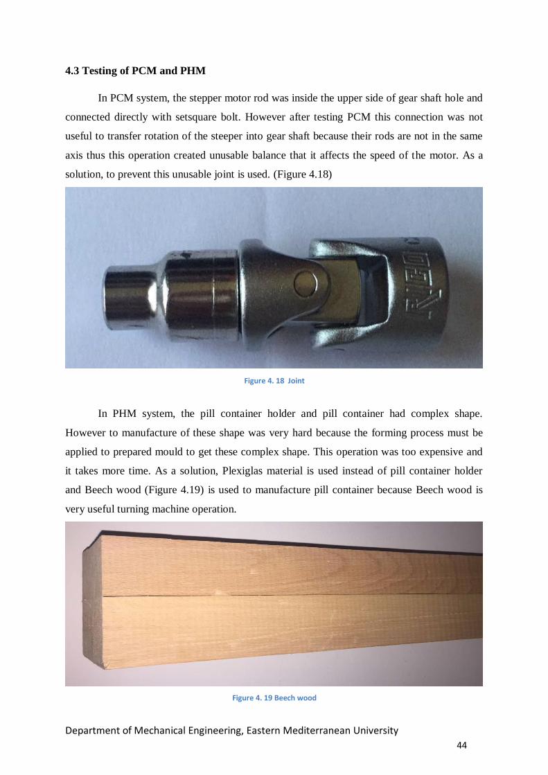
4.3 Testing of PCM and PHM
In PCM system, the stepper motor rod was inside the upper side of gear shaft hole and
connected directly with setsquare bolt. However after testing PCM this connection was not
useful to transfer rotation of the steeper into gear shaft because their rods are not in the same
axis thus this operation created unusable balance that it affects the speed of the motor. As a
solution, to prevent this unusable joint is used. (Figure 4.18)
Figure 4. 18 Joint
In PHM system, the pill container holder and pill container had complex shape.
However to manufacture of these shape was very hard because the forming process must be
applied to prepared mould to get these complex shape. This operation was too expensive and
it takes more time. As a solution, Plexiglas material is used instead of pill container holder
and Beech wood (Figure 4.19) is used to manufacture pill container because Beech wood is
very useful turning machine operation.
Figure 4. 19 Beech wood

Department of Mechanical Engineering, Eastern Mediterranean University
45
4.4 Ironmongery Engineering Standard for Assembly
In assembly of Ethernet Automatic Pill Dispenser (e-APD), much kind of
ironmongeries are used to fix and support all part of machine and also a nut is used to convert
rotation movement into linear movement. Engineering Standard of these ironmongeries is
described below.
4.4.1 Nut-Bolt Nut and bolt are part of a machine element that makes the task of tightening the
connection. Nuts are made according to bolt measurements. They are usually made of steel
and nut is a type of fastener with a threaded hole. Nuts are almost always used opposite a
mating bolt to fasten a stack of parts together as seen in Figure 4.20.Standarts of the nut
shown in the Appendix D.
Figure 4. 20 Part of Name Nut and Bolt [20]
4.4.2 Steel Threaded Rod
Standard threaded rods are pre-threaded bars used with standard nuts, couplers and
washers. It is very useful to connect machine part each other whatever the distance between
them. In PHM and PCM system, M8 steel threaded rod is used to convert rotation movement
into linear movement with M8 nut and M6 steel threaded rod is used to connect and fix all
parts each other.(See in Appendix D.) [24]. Some steel threaded rods are shown in Figure
4.21.
Figure 4. 21 Steel Threaded Rod [22]
4.4.3 Setsquare Bolt

Department of Mechanical Engineering, Eastern Mediterranean University
46
A Setsquare Bolt is a type of screw or bolt generally used to safe an object within or
against another object,(see in Figure 4.22) normally not using like a nut. The most common
examples are connecting a pulley or gear to a shaft. In the project, each motor rod and pulley
and joint are fixed each other by using setsquare bolt. There are many types of setsquare bolt
in the market.(See in the Appendix D).[25]
Figure 4. 22 Setsquare Bolt [23]

Department of Mechanical Engineering, Eastern Mediterranean University
47
CHAPTER 5
RESULT AND DISCUSSION
Ethernet Automatic Pill Dispenser e-APD is very useful machine in daily life for elderly
people and people who have Alzheimer disease. It has specific software which communicates
with the Arduino via Internet. This software provides facility for a doctor to determine the
pills which will be taken by the patient on the time.
Although the linear mill was connected to the stepper motor in the system, balance
problem was occurred at the top of e-APD then the mill was tried to fix but problem was
continued. After some research on the Internet, specific joint was used to overcome this
problem. Another problem was occurred in the different motor which rotates the middle
mechanism. In order to solve this problem belt was used to transmit the rotation of the stepper
motor.
Beginning of the project, it was decided to use plastic container which contains the pills.
Because of the disadvantages of plastic such as low melting temperature during process,
decided to use wood for containers. Being organic and low decomposition are some of several
advantages of the wood. Another issue was some measurement that had to be changed during
manufacturing.
Considerable innovation is in the software part. Before start the mechanical part, software
part was done but the problem was on the design. Interface was redesigned. Another problem
was in the Arduino programing. After mechanical part became palpable, problem was
occurred. After research on the Internet some specific codes were used and problem was
solved.

Department of Mechanical Engineering, Eastern Mediterranean University
48
CHAPTER 6
CONCLUSION AND FUTURE WORK
6.1 Conclusion
Basic pill dispenser is widely used in medicine. However it has been tried to develop
as much as possible using today’s technology. For example, some mechanical parts and
electronic kits which are Arduino and sensors. This project was undertaken with an objective
learn how to program an Arduino and design mechanical parts and the importance of proper
selection of materials for the project.
During the procedure of the project, we have gained knowledge about design,
calculation, theories, production some material and Arduino programming. For example
Plexiglas was used in the project. It was used because it is inexpensive, lightweight and easy
machinable. And some materials that used in the Capstone Project were brought from Turkey
and China such as current sensor, Arduino etc.
On the other hand, software for the Automatic Pill Dispenser was designed and
developed with members of capstone team. During this period, some specific software’s were
used such as C# (C Sharp), Photoshop (for editing logos and images), Microsoft Access (for
database). And software design is described below step by step. The purpose of using
software design in the project to provide ease of use and controlling the machine in this way
the software design helps us to reach our main aim which is to help elderly people who forget
to take their pill on time and will make life of patients and their relatives easier.
6.1.1 Software Design
6.1.1.1 Username and Password Control
Automated Pill Dispenser (APD) is occurring from forms or windows. Firstly to use
Automated Pill Dispenser (APD), user has to enter own username and password as shown in
Figure 6.1. After this dialog, main menu will be open. If user enters wrong password and
username, one warning dialog gives warning as shown in Figure 6.2 and if enters more than 3
times, program close itself because of security as shown in Figure 6.3. Microsoft Access
Database is used to hide Login information as shown in Figure 6.4 . It is possible to change
username and password after the login dialog.

Department of Mechanical Engineering, Eastern Mediterranean University
49
Figure 6. 1 Username and Password Control
Figure 6. 2 Wrong Username and Password Control

Department of Mechanical Engineering, Eastern Mediterranean University
50
Figure 6. 3 Warning When More than Three Times Entering Wrong Information
.
Figure 6. 4 Saving LOGIN Information to Database

Department of Mechanical Engineering, Eastern Mediterranean University
51
After the successfully entering login information, main menu will be open as shown in
Figure 6.5 and main menu has a two option
a- Shows existing patient
b- Add new patient
Figure 6. 5 Main Menu
a- Shows Existing Patient
In this window, it is requires to search patient ID. If patient ID exists on the Database
then shows on the list view as shown in Figure 6.6. In here, there are three options. One of the
options is deleting the patient information as permanently from the database. Second option is
updating patient information as shown in Figure 6.7 . And third option is connection and
settings with machine.
Figure 6. 6 Searching Existing Patient by ID
Option 1
Option 2

Department of Mechanical Engineering, Eastern Mediterranean University
52
In here Muammer is selected and updating patient information option clicked and then
new form shows all information of Muammer. This information is hiding in the Database. In
here only ID can’t change because of the security and every person has a unique ID number.
Figure 6. 7 Update Patient Information
If user double clicks selected patient information thus machine connection page will
be open. In here, it’s necessary to enter machine IP address and port name according to the
machine. In this project, IP address is 192.168.2.17 and port number is 23. (Figure 6.8)
Figure 6. 8 Machine Connection

Department of Mechanical Engineering, Eastern Mediterranean University
53
After connecting to the machine there will be open new form which contains 3 different
settings. It is necessary to choose medicine taking hours and need to send to the machine. If
there is no medicine, selecting to taking medicine hours is not possible as shown in Figure
6.9. Also data will be saved on the database and when data transfer complete, bottom of the
form there will be message to show data transfer situation which is shown in bottom of Figure
6.8 and Figure 6.10.
Figure 6. 9 Machine Settings
Figure 6. 10 Selecting to the Taking to Medicine Time

Department of Mechanical Engineering, Eastern Mediterranean University
54
b- Add new patient
This option is for add new patient. The form is shown as an option 2 in Figure 6.5. In
here it’s necessary to fill all empty space. Otherwise adding new patient is not possible. It is
also saving the registration date and time automatically.
6.1.1.2 File Option
Under the file there is an option which is exit. It is used for closing the program as shown
in Figure 6.11.
Figure 6. 11 File Menu and Exiting from the Program
6.1.1.3 Edit Option
Under the edit option, Doctor Information can be open and edit the information as shown
in Figure 6.12 and Figure 6.13.
Figure 6. 12 Edit Doctor Information

Department of Mechanical Engineering, Eastern Mediterranean University
55
Figure 6. 13 Edit Doctor Information
6.1.1.4 Tools Option
Under the tools option, username and password can be change as shown in Figure 6.14
and Figure 6.15.
Figure 6. 14 Changing the password 1
Figure 6. 15 Changing the password 2

Department of Mechanical Engineering, Eastern Mediterranean University
56
6.1.1.5 Help Option
There are two options under the help option as shown in Figure 6.16 and Figure 6.17.
a- Support
Figure 6. 16 Contact us
b- About Automated Pill Dispenser
Figure 6. 17 About Automated Pill Dispenser
6.2 Future Works
Ethernet Automatic Pill Dispenser (e-APD) is compound of mechanical structure,
electronic materials and Arduino. e-APD communicates with Arduino using interface that on
the doctors’ computer. APD has 3 different containers which contain 3 different pills.
Applicability of pill dispenser is promising for future works. In addition, it can be developed
easily.

Department of Mechanical Engineering, Eastern Mediterranean University
57
As known that, e-APD has software in the PC. One of these developments is using it
in the mobile application for android or iOS. Another development can be feedback. For
example using some specific sensors in the e-APD, program can detect whether patient takes
the pills or not and patient relatives or the doctor can be informed via SMS or e-mail.
Another way of developing of e-APD is that using smart clock that can be used for blood
pressure measurement and heart beat changes and inform the relatives of patient and doctor.
Also there can be an emergency button on the machine. When press it, doctors may be
informed and ambulance can be called. For interface, a button can be added which reset the
password. These innovations or developments are limited by human imagination.

Department of Mechanical Engineering, Eastern Mediterranean University
58
REFERENCES [1] Retrieved 6 December, 2015 from
http://liveimageserver.dlf.org.uk/mee//products/full/0040079-0044049-29778.jpg
[2] Dynamic Advertising Group (2015) Unused prescription medicines cost the NHS in the
UK an estimated £300million every year. Retrieved from 25 December 2015
http://www.medicinewaste.com/didyouknow
[3] ROSIE M. The Colorful History of Pills Can Fill Many a Tablet. Retrieved 25 October
2015 from
http://articles.latimes.com/2002/mar/25/health/he-booster25
[4] AUGUST H. W. Making-Pill machines, Patent No. 69,379 (1867)
http://www.google.com/patents/US69379?hl=tr
[5] Stuart A, (2005). Making-Medicine. London, UK: Pharmaceutical Press
[6] Justin Caba , Generic Pill Size and Shape Could Determine Whether The Patient Will Adhere To
Medication Regimen. Retrieved 14 November 2015 from http://www.medicaldaily.com/generic-
pill-size-and-shape-could-determine-whether-patient-will-adhere-medication-regimen-
292958
[7] W Kistner, The Pill; Facts and rallacies About Todays Oral Contraceptil Jes (New York,
1968).
http://www.artefactsconsortium.org/Publications/PDFfiles/Vol1Med/1.05.Medicine-
Gossel,PackagingThePillGrBlank3AWEBF.pdf
[8] Murray MD. Information technology: the infrastructure for improvements to the
medication-use process. Am J Health Syst Pharm 2000; 57:565-571. Retrieved 16 November
2015 from http://archive.ahrq.gov/clinic/ptsafety/chap11.htm.
[9] Stepper motor. (February 9,2015). Retrieved on 14 November 2015 from
http://en.wikipedia.org/wiki/Stepper_motor
[10] Dfr, Alex. (May 06, 2013). Retrieved on 14 November 2015 from
http://tr.scribd.com/doc/139717811/ST-PM35-15-11C#scribd
[11] Lu, Chuanzhi. (n.d). Retrieved on 14 November 2015 from
http://www.aliexpress.com/item/Top-Selling-DC-12V-50Kpa-DC-Micro-Vacuum-Pump-
Pumping-Air-pump-Air-sampling-Liquid-Pump/32475635660.html

Department of Mechanical Engineering, Eastern Mediterranean University
59
[12 ]Retrieved 19 December, 2015 from
http://www.plexiglas.com/export/sites/plexiglas/.content/medias/downloads/sheet-
docs/plexiglas-general-information-and-physical-properties.pdf
[13] Zo-Mont (2014). Plexiglas Retrieved 12 December, 2015 from
http://www.zomont.rs/materijali/plexiglas/
[14] Retrieved 19 December, 2015 from
http://www.csidesigns.com/PDFs/SSSguide.pdf
[15] Retrieved 12 December, 2015 from
http://www.onlinemetals.com/graphics/Group_StainlessSpecialtySheet_620.jpg.
[16] Retrieved 19 December, 2015 from
http://www.plasticsintl.com/thermoplastic_selection_guide.html
[17] Chris Red (2014), The Outlook for Thermoplastics in Aerospace Composites. Retrieved
19 December, 2015 from
http://www.compositesworld.com/articles/the-outlook-for-thermoplastics-in-aerospace-
composites-2014-2023
[18]Retrieved 12 December, 2015 from
http://www.bronzreklamcilik.com/d27/pvc_foam_levha
[19] Retrieved 12 December, 2015 from
http://www.automationdirect.com/images/overviews/nitra_poly_tubing_200.jpg
[20] Retrieved 12 May, 2016 from
https://www.google.com.tr/search?q=nut+and+bolt&espv=2&biw=1517&bih=714&source=l
[21] Retrieved 12 May, 2016 from
http://image.slidesharecdn.com/dimensionsofmetrichexnuts-121221090634-
phpapp01/95/dimensions-of-metric-hex-nuts-1-638.jpg?cb=1356080846
[22] Retrieved 12 May, 2016 from
http://www.discountsteel.com/files/image/oms_product/medium/stainlesssteel-
threadedrods.jpg
[23] Retrieved 12 May, 2016 from
http://www.misirlicivata.com/misirlicivata/civatalar/7.jpg
[24] Retrieved 21 June, 2016 from
http://www.aaatech.com/hardware/pipe-rods/images/403_pipe_rodsxz.png
[25] Retrieved 21 June,, 2016 from
http://www.metalartspress.com/sites/default/files/chapter-images/mse-chapter9-image007.gif

Department of Mechanical Engineering, Eastern Mediterranean University
60
APPENDICES

Department of Mechanical Engineering, Eastern Mediterranean University
61
APPENDIX A
LOGBOOKS Hakan’s Logbook
12.10.2015 First of all, we search the some Project and
we discuss together with our friends.
19.10.2015
This week we decided to Pill Dispenser
Project with our friends and our advisor
Assist. Prof. Dr. Davut SOLYALI
26.10.2015
I find the some information about the Project
and also I start to prepare the Gantt chart.
02.11.2015
We start to research of our project that
Automated Pill Dispenser Systems we
collect the general information
09.11.2015 We visit the our advisor and we give the
information what we are doing for the project
16.11.2015
We visited our advisor to get information
about the Project and we distribute the duty
in our group.
23.11.2015
I search the information about the Project
what we use in this Project, how we can
develop this project.

Department of Mechanical Engineering, Eastern Mediterranean University
62
24.11.2015
I learn lots of thinks about the e-APD
system like working principle
30.11.2015
I prepared appendix, Gantt chart and my
logbooks for the final report. Also I did
some calculation
02.12.2015
I did some calculation about the Project. I
discuss with my friend how we can fix the
part. Also I collect the information for the
final report.
07.12.2015
I continue the collect the information and I
prepare the proposal with my friends. Also
I start to write Chapter 2.
14.12.2015
I finished the proposal with my friends and
I continue the write the Chapter 2 and I
help to somewhere in chapter 1 to my
friends.
21.12.2015
I finished the Chapter 2 and also we finished
the writing formula and calculation.
28.12.2015 I prepared appendix, Gantt chart and my
logbooks for the final report.
10.02.2016 Plexiglas design and measurements are
discussed with team members.
11.02.2016 Plexiglas was machined according to the
design in Turkey.

Department of Mechanical Engineering, Eastern Mediterranean University
63
23.02.2016 New design assembled on the SolidWorks.
01.03.2016 Project raw materials were bought.
02.03.2016
C# interface was discussed with Assist.
Prof. Dr. Davut SOLYALI and new ideas
and new design were found out.
08.03.2016
Assembly was discussed with Hamed
POURASL for the machine on CNC
machine.
15.03.2016 Step motor drivers problem solved with
Ayhan ÖZGÜR.
29.03.2016
Step motor connection mil machined and
mil ball bearing bed machined according the
drawings
01.04.2016 Ball bearing bed machined and tested.
25.04.2016 Some parts machined on the CNC machine
with Hamed POURASL
04.05.2016 After the CNC machine, parts machined on
the workshop and tested.
11.05.2016 Mill, bearing and step motor were
assembled.

Department of Mechanical Engineering, Eastern Mediterranean University
64
18.05.2016 Step motor was tested on the assembled and
requires adjustment (balance) was made
20.05.2016
Step motor platform was failed and new
ideas was found with technician Servet
UYANIK
21.05.2016 Middle platform was assembled and step
motor mechanics were machined
27.05.2016 Middle platform assembled is finished and
tested.

Department of Mechanical Engineering, Eastern Mediterranean University
65
Muammer’s Logbook
12.10.2015 First of all, we search the some Project and
we discuss together with our friends.
19.10.2015
This week we decided to Pill Dispenser
Project with our friends and our advisor
Assist. Prof. Dr. Davut SOLYALI
26.10.2015 I start to prepare the Gantt chart.
02.11.2015
We start to research of our project that
Automated Pill Dispenser Systems we
collect the general information
09.11.2015
I continue the collect the information about
the ASRS and I try to learn Automated Pill
Dispenser systems. Also we visit our advisor
and we give the information what we are
doing.
16.11.2015
We visited our advisor to get information
about the Project and we distribute the duty
in our group.
23.11.2015
We search the information about the Project
what we use in this Project like sensors,
design, etc.
24.11.2015
I prepared appendix, Gantt chart and my
logbooks for the final report.
30.11.2015
I draw the design of ASRS system
with my Project member from
SolidWorks.

Department of Mechanical Engineering, Eastern Mediterranean University
66
02.12.2015
I did some calculation about the Project. I
discuss with my friend How we can fix
the part. Also I collect the information for
the final report.
07.12.2015
I continue the collect the information and
I prepare the proposal with my friends.
Also I start to write Chapter 3.
14.12.2015
I finished the proposal with my friends
and I continue the write the Abstract.
21.12.2015
I finished the Chapter 3 and also we
finished the writing formula and
calculation.
28.12.2015 I prepared appendix, Gantt chart and my
logbooks for the final report.
10.02.2016 Plexiglass design and measurements are
discussed with team members.
11.02.2016 Electronic material was bought.
23.02.2016 New design assembled on the SolidWorks.
01.03.2016 C sharp and Arduino connection was
tested.
02.03.2016
C# interface was discussed with Assist. Prof.
Dr. Davut SOLYALI and new ideas and new
design were found out.

Department of Mechanical Engineering, Eastern Mediterranean University
67
08.03.2016 Real time clock module was tested.
15.03.16 Step motor drivers were chanced and
tested.
29.03.2016 Step motors were assembled on the
machine and tested.
01.04.2016 Arduino sensors were tested.
04.04.2016 Ethernet module problem was solved.
11.05.2016 Step motors adjustment was done on the
mechanical part
20.05.2016
Step motor platform was failed and new ideas
was found with technician Servet UYANIK
27.05.2016
Middle platform assembled is finished and
tested.

Department of Mechanical Engineering, Eastern Mediterranean University
68
Abdullah’s Logbook
12.10.2015 First of all, we search the some Project
and we discuss together with our friends.
19.10.2015
This week we decided to Pill Dispenser
Project with our friends and our advisor
Assist. Prof. Dr. Davut SOLYALI
26.10.2015 I start to prepare the Gantt chart.
02.11.2015
We start to research of our project that
Automated Pill Dispenser Systems we
collect the general information
09.11.2015
We visit our advisor and we give the
information what we are doing. Also I
search the information about the Project
material.
16.11.2015
We visited our advisor to get information
about the Project and we distribute the
duty in our group.
23.11.2015 I search the information about the Project
what we use in this Project like sensors,
design, etc.
12.10.2015
I learn lots of thinks about the e-APD
system like working principle. I draw the
concept design.
19.10.2015
I prepared appendix, Gantt chart and
my logbooks for the final report.

Department of Mechanical Engineering, Eastern Mediterranean University
69
24.11.2015
I draw the design of e-APD system with
my Project member from SolidWorks.
30.11.2015
I did some calculation about the Project. I
discuss with my friend what we will use
for the design. Also I collect the
information for the final report.
02.12.2015
I continue the collect the information and
I prepare the proposal with my friends.
Also I start to write Chapter 1.
07.12.2015 I finished the proposal with my friends and
I continue the write the Chapter 1.
14.12.2015
I finished the Chapter 1 and also I
finished the writing formula and
calculation.
21.12.2015 I prepared appendix, Gantt chart and
my logbooks for the final report.
28.12.2015 Working on assembling and resulting the
final report for the submission,
10.02.2016
Plexiglas design and measurements are
discussed with team members.
20.02.2016 C sharp menu designed was searched.

Department of Mechanical Engineering, Eastern Mediterranean University
70
21.02.2016 Electronic material was bought
23.02.2016 New design assembled on the SolidWorks
01.03.2016 C sharp and Arduino connection was tested.
02.03.2016
C# interface was discussed with Assist. Prof.
Dr. Davut SOLYALI and new ideas and new
design were found out.
05.03.2016 New c sharp menu designed.
08.03.2016 Arduino Ethernet module tested and data
transfer successfully done.
17.03.2016 C sharp menu discussed with team members
01.04.2016 C sharp database was created
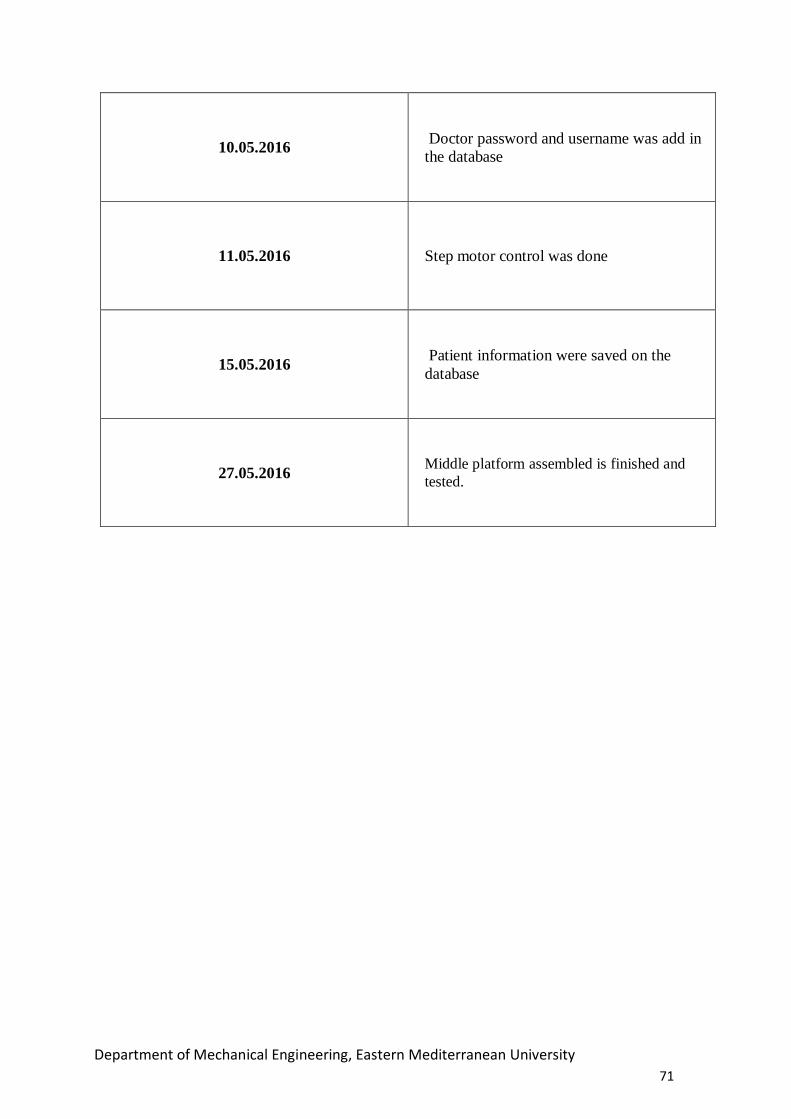
Department of Mechanical Engineering, Eastern Mediterranean University
71
10.05.2016 Doctor password and username was add in
the database
11.05.2016 Step motor control was done
15.05.2016 Patient information were saved on the
database
27.05.2016 Middle platform assembled is finished and
tested.

Department of Mechanical Engineering, Eastern Mediterranean University
72
APPENDIX B
GANTT CHART
1
2.0
9.2
01
5
19
.09
.20
15
26
.09
.20
15
02
.11
.20
15
09
.11
.20
15
16
.11
.20
15
23
.11
.20
15
30
.11
.20
15
07
.12
.20
15
14
.12
.20
15
21
.12
.20
15
28
.12
.20
15
Selecting project
Start to preparing Gantt chart
Searching information about the project
Learning to Pill dispenser system
Distribution of duty
Design and calculation
Collecting information
Preparing to proposal
Preparing to report writing
Writing chapter 1, 2 and 3
Writing formula and calculation
Resulting the final report

Department of Mechanical Engineering, Eastern Mediterranean University
73
10
.02
.20
16
17
.02
.20
16
24
.02
.20
16
02
.03
.20
16
09
.03
.20
16
16
.03
.20
16
23
.03
.20
16
30
.03
.20
16
06
.04
.20
16
13
.04
.20
16
20
.04
.20
16
27
.04
.20
16
04
.05
.20
16
11
.05
.20
16
18
.05
.20
16
25
.05
.20
16
Design of Plexiglas and
cutting
Electronic material search
Searching information about the vacuum
Searching Arduino and C sharp connection
Step Motor driver and sensor delivery
Designing main structure
Adding stepper motor and testing
Bearing beds machined
material cutting on the CNC machine
Program writing in Arduino and C sharp
Preparing control box
Table 5: Distribution of Tasks

Department of Mechanical Engineering, Eastern Mediterranean University
74
DISTRIBUTION OF TASKS HAKAN MUAMMER ABDULLAH
PLEXIGLASS DECISION PLEXIGLASS PURCHASING
X X X
X
MATERIAL SELECTION X X X
MOTOR SELECTION X X X
MILL SELECTION AND PURCHASING X X
PLEXIGLASS ASSEMBLY X X X
C SHARP MENU IDEA X X
PILL HOLDER MECHANISM IDEA X
MIDDLE MECHANISM IDEA X X
MIDDLE SYSTEM DESIGN X X X
CUTTING PLASTIC MATERIAL ON CNC X
VACUUM PUMP IDEA X X X
SOLIDWORK DESIGN X
STEPPER MOTOR ASSEMBLY X X X
STEPPER MOTOR ASSEMBLY X X
MIDDLE MECHANISM ASSEMBLY X X
CHAIN AND MOTOR MIL IDEA X
ELECTRONICS AND CABLE CONNECTIONS X
ARDUINO X
C SHARP X
REPORT WRITING X X X
SOLIDWORKS DESIGN X X X
SOLVING MECHANICAL PROBLEMS X X X
CONTROLLER BOX X X X

Department of Mechanical Engineering, Eastern Mediterranean University
75
APPENDIX C
DRAWING

1
3
4
2
5
SCALE1:4
DRAWING NO
EMU22/06/1622/06/16
D. SOLYALI121776
CHK. BY
NAMEDATE SIGN
PILL DISPENSER ASSEMBLY 1
NO NAME AMOUNT DESCRIPTION12345
BODY OF MACHINEPILL CONTAINER MECHANISMPILL HOLDER MECHANISMWATER TANKM3 NUTS AND BOLTS
111152
PLEXIGLASSPLEXIGLASS
PLASTICSTS 1026-1
PLEXIGLASS
DRW. BY

5
1
7
3
4
26
SCALE1:5
DRAWING NO
EMU22/06/16D. SOLYALI121776
CHK. BY
NAMEDATE SIGN
1-1
NO NAME AMOUNT DESCRIPTION1234
6
DOORTOP OF THE MACHINEUPPER SUPPORT OF THE PLEXIGLASS
11444
PLEXIGLASSPLEXIGLASS
PLEXIGLASSALUMINUM
ALUMINUM
DRW. BY
5
FRONT SIDE OF THE MACHINE23
PLEXIGLASS
BODY OF MACHINE
BOTTOM SUPPORT OF THE PLEXIGLASSLOWER SUPPORT OF THE PLEXIGLASS
7 PLEXIGLASSCOVER OF THE WATER AND PILL TANK
22/06/16

800
400
DRW. BYCHK. BYSCALE1:5
121776D. SOLYALI
22/06/16SIGNDATENAME
EMU
DRAWING NO1-1-1DOOR
NOTESREMOVE ALL SHARP EDGES1.TICKNESS IS 5MM2.MATERIAL IS PLEXIGLASS3.
22/06/16
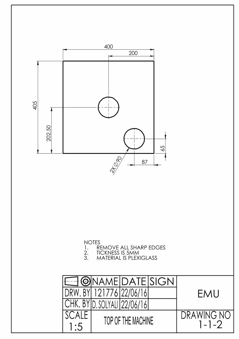
405
400
65
87
200 2
02,5
0
2X
90
DRW. BYCHK. BYSCALE1:5
121776D. SOLYALI
22/06/16SIGNDATENAME
EMU
DRAWING NO1-1-2TOP OF THE MACHINE
NOTESREMOVE ALL SHARP EDGES1.TICKNESS IS 5MM2.MATERIAL IS PLEXIGLASS3.
22/06/16

800
DRW. BYCHK. BYSCALE1:5
121776D. SOLYALI
22/06/16SIGNDATENAME
EMU
DRAWING NO1-1-3
NOTESREMOVE ALL SHARP EDGES1.25X25 SQUARE PROFILE2.
22/06/16UPPER SUPPORT OF THE PLEXIGLASS

405
400
DRW. BYCHK. BYSCALE1:5
121776D. SOLYALI
22/06/16SIGNDATENAME
EMU
DRAWING NO1-1-4LOWER SUPPORT OF THE MACHINE
NOTESREMOVE ALL SHARP EDGES1.TICKNESS IS 5MM2.
22/06/16

350
DRW. BYCHK. BYSCALE1:5
121776D. SOLYALI
22/06/16SIGNDATENAME
EMU
DRAWING NO1-1-5
NOTESREMOVE ALL SHARP EDGES1.25X25 SQUARE PROFILE2.
BOTTOM SUPPORT OF THE PLEXIGLASS22/06/16

2,50
95
10
0
DRW. BYCHK. BYSCALE1:5
121776D. SOLYALI
22/06/16SIGNDATENAME
EMU
DRAWING NO1-1-6
COVER OF THE WATER AND PILL TANK
NOTESREMOVE ALL SHARP EDGES1.TICKNESS IS 5MM2.MATERIAL IS PLEXIGLASS3.
22/06/16

800
400
150
100
85
70 60
DRW. BYCHK. BYSCALE1:5
121776D. SOLYALI
22/06/16SIGNDATENAME
EMU
DRAWING NO1-1-7FRONT SIDE OF THE MACHINE
NOTESREMOVE ALL SHARP EDGES1.TICKNESS IS 5MM2.MATERIAL IS PLEXIGLASS3.
22/06/16

1
2
4 5
6
7
3
8
9
SCALE1:2
DRAWING NO
EMU22/06201622/06/2016D. SOLYALI
121776DRW. BYCHK. BY
NAME DATE SIGN
PILL CONTAINER ASSEMBLY 1-2
NO NAME AMOUNT DESCRIPTION123456
BEARING BED LOWER PARTBEARING BED UPPER PARTTHREADED RODSTEPPER MOTOR HOLDERM6 THREADED ROD
1
4PLEXIGLASS HOLDER
78
ALUMINUM SHEET PLATEPLEXIGLASS
2PLEXIGLASSALUMINUM
PLASTIC
STAINLESS STEEL LOW CARBON STEEL
9 PILL CUP 3 HORNBEAM WOOD
PLASTIC
LOW CARBON STEELLOW CARBON STEEL
111
1
1

150
80
10
10
4x7
22 11 25.80 8
15
DRW. BYCHK. BYSCALE1:1
121776D. SOLYALI
22/06/201622/06/2016
SIGNDATENAMEEMU
DRAWING NO1-2-1BEARING BED LOWER PART
NOTESREMOVE ALL SHARP EDGES1.DO NOT MEASURE2.

150 8
0
10
10
60
130
65
40
4X
7
10 15 22 11 25.80 8
15
DRW. BYCHK. BYSCALE1:1
121776D. SOLYALI
22/06/201622/06/2016
SIGNDATENAMEEMU
DRAWING NO1-2-2BEARING BED UPPER PART
NOTESREMOVE ALL SHARP EDGES1.DO NOT MEASURE2.

9,60
M10X1.25
140
1
20
290
12
DRW. BYCHK. BYSCALE1:2
121776D. SOLYALI
22/06/201622/06/2016
SIGNDATENAMEEMU
DRAWING NO1-2-3TREATED ROD
NOTES1. REMOVE ALL SHARP EDGES

80,
50
160
6
4,25
10,
25
4X3
32
60
10,25 10,
25
2XR3,50
139,50
16 2x
7
39,75
30
DRW. BYCHK. BYSCALE1:1
121776D. SOLYALI
22/06/201622/06/2016
SIGNDATENAMEEMU
DRAWING NO1-2-4STEPPER MOTOR HOLDER
NOTESREMOVE ALL SHARP EDGES1.THICKNESS IS 2 MM2.DO NOT MEASURE3.

200
D M6X1
DETAIL D SCALE 2 : 1
DRW. BYCHK. BYSCALE1:1
121776D. SOLYALI
22/06/201622/06/2016
SIGNDATENAMEEMU
DRAWING NO1-2-5M6 THREATED ROD
NOTESREMOVE ALL SHARP EDGES1.DO NOT MEASURE2.

25
45
20
30
10
35
4X5
17,50 35
DRW. BYCHK. BYSCALE1:1
121776D. SOLYALI
22/06/201622/06/2016
SIGNDATENAMEEMU
DRAWING NO1-2-6PLEXIGLASS HOLDER
NOTESREMOVE ALL SHARP EDGES1.DO NOT MEASURE2.
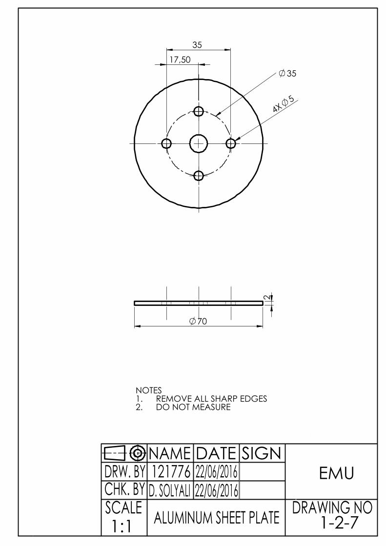
4X5
17,50
35
35
70
2
DRW. BYCHK. BYSCALE1:1
121776D. SOLYALI
22/06/201622/06/2016
SIGNDATENAMEEMU
DRAWING NO1-2-7ALUMINUM SHEET PLATE
NOTESREMOVE ALL SHARP EDGES1.DO NOT MEASURE2.

4X 5
17,50
70
9,60
127,28
180
300
5
DRW. BYCHK. BYSCALE1:2
121776D. SOLYALI
22/06/201622/06/2016
SIGNDATENAMEEMU
DRAWING NO1-2-8PLEXISIGLASS
NOTES1. REMOVE ALL SHARP EDGES

60
9.5
5
74
80 67
80 5
DRW. BYCHK. BYSCALE1:1
121776D. SOLYALI
22/06/201622/06/2016
SIGNDATENAMEEMU
DRAWING NO1-2-9PILL CUP
NOTESREMOVE ALL SHARP EDGES1.DO NOT MEASURE2.

1
2
3
5
6
7
8
4
910
11
12
SCALE1:0.75
DRAWING NO
EMU22/06/201622/06/2016D. SOLYALI
121776DRW. BYCHK. BY
NAME DATE SIGN
PILL HOLDER MECHANSIM 1-3
NO NAME AMOUNT DESCRIPTION123456
BEARING BED LOWER SUPPORT PARTBEARING BED LOWER PARTBEARING BED UPPER PARTBEARING BED UPPER SUPPORT PARTCONNECTION PART
11
3M6 THREADED ROD78
SUPPORT RODSTEPPER MOTOR SUPPORT PART
LOW CARBON STEELPLASTIC
91011
T PART
PIE HOLDERALUMINIUM PIPE
PLASTICLOW CARBON STEELPLASTICLOW CARBON STEEL
ALUMINIUM
12
LOW CARBON STEELLOW CARBON STEEL
PLASTICPLASTICALUMINIUM
111
111111
VACUUM AL. PIE HOLDER

67
100
3X6
R3,75
10
10
23
21
60
40
25
35
R53
DRW. BYCHK. BYSCALE1:1
121776D. SOLYALI
22/06/201622/06/2016
SIGNDATENAMEEMU
DRAWING NO1-3-1BEARING BED LOWER SUPPORT PART
NOTESREMOVE ALL SHARP EDGES1.THICKNESS IS 2MM2.DO NOT MEASURE3.

50
70
3X
6
10
10 2
5
35 60
40
13 7 16 5
8
DRW. BYCHK. BYSCALE1:1
121776D. SOLYALI
22/06/201622/06/2016
SIGNDATENAMEEMU
DRAWING NO1-3-2BEARING BED LOWER PART
NOTESREMOVE ALL SHARP EDGES1.DO NOT MEASURE2.

50
70
10
10
3X
6
25
35 60
40
5,5 3 16 5
8
DRW. BYCHK. BYSCALE1:1
121776D. SOLYALI
22/06/201622/06/2016
SIGNDATENAMEEMU
DRAWING NO1-3-3BEARING BED UPPER PART
NOTESREMOVE ALL SHARP EDGES1.DO NOT MEASURE2.

67
100
3X6
10
10
5,50
R3,75
23 2
1
35
25
60
40
R53
DRW. BYCHK. BYSCALE1:1
121776D. SOLYALI
22/06/201622/06/2016
SIGNDATENAMEEMU
DRAWING NO1-3-4BEARING BED UPPER SUPPORT PART
NOTESREMOVE ALL SHARP EDGES1.THICKNESS IS 2MM2.DO NOT MEASURE3.

19
7,45
8,90 20
12
1,2
4
8,90
DRW. BYCHK. BYSCALE1:1
121776D. SOLYALI
22/06/201622/06/2016
SIGNDATENAMEEMU
DRAWING NO1-3-5CONNECTION PART
NOTESREMOVE ALL SHARP EDGES1.DO NOT MEASURE2.

299
A M6X1
DETAIL A SCALE 5 : 1
DRW. BYCHK. BYSCALE2:1
121776D. SOLYALI
22/06/201622/06/2016
SIGNDATENAMEEMU
DRAWING NO1-3-6M6 TREADED ROD
NOTES1. REMOVE ALL SHARP EDGES

2XM6X1
16
157
14
SLOT 1 WIDE X 1,46 DEEP
7
DRW. BYCHK. BYSCALE1:1
121776D. SOLYALI
22/06/201622/06/2016
SIGNDATENAMEEMU
DRAWING NO1-3-7BEARING BED UPPER PART
NOTESREMOVE ALL SHARP EDGES1.DO NOT MEASURE2.
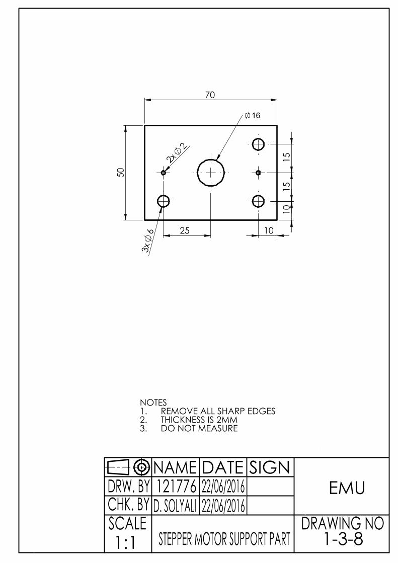
50
70
3x
6 2x
2
10
10
25
15
15
16
DRW. BYCHK. BYSCALE1:1
121776D. SOLYALI
22/06/201622/06/2016
SIGNDATENAMEEMU
DRAWING NO1-3-8STEPPER MOTOR SUPPORT PART
NOTESREMOVE ALL SHARP EDGES1.THICKNESS IS 2MM2.DO NOT MEASURE3.

8
12
22
5 39,
50
DRW. BYCHK. BYSCALE2:1
121776D. SOLYALI
22/06/201622/06/2016
SIGNDATENAMEEMU
DRAWING NO1-3-9T-PART
NOTES1. REMOVE ALL SHARP EDGES2. THICKNESS IS 1MM

20
10 1
0
20 100
5
19
DRW. BYCHK. BYSCALE1:1
121776D. SOLYALI
22/06/201622/06/2016
SIGNDATENAMEEMU
DRAWING NO1-3-10VACUUM ALUMINIUM PIE HOLDER
NOTESREMOVE ALL SHARP EDGES1.DO NOT MEASURE2.

30
19
20 5,50
26
50
19
8 10
5
DRW. BYCHK. BYSCALE2:1
121776D. SOLYALI
22/06/201622/06/2016
SIGNDATENAMEEMU
DRAWING NO1-3-11PIE HOLDER
NOTES1. REMOVE ALL SHARP EDGES

95
3/4 (inch)
DRW. BYCHK. BYSCALE1:1
121776D. SOLYALI
22/06/201622/06/2016
SIGNDATENAMEEMU
DRAWING NO1-3-12ALUMINIUM PIPE
NOTESREMOVE ALL SHARP EDGES1.MATERIAL IS ALUMINIUM2.DO NOT MEASURE3.

PWM COMUNICATION
DIGITA
L
ANALOG IN
ATMEGA256016AU 1126
microcontrolandos.blogspot.com
TX0
TX3
TX2
TX1 SD
ASC
L
RX0
RX3
RX2
RX1
PD0/S
CL/IN
T021
PD1/S
DA/IN
T120
PD2/R
XD1/IN
T219
PD3/T
XD1/IN
T318
PH0/R
XD2
17PH
1/TXD
216
PJ0/R
XD3/P
CINT9
15PJ
1/TXD
3/PCIN
T10
14PE
0/RXD
0/PCIN
T80
PE1/T
XD0/P
DO1
PE4/O
C3B/I
NT4
2PE
5/OC3
C/INT
53
PG5/O
C0B
4PE
3/OC3
A/AIN1
5PH
3/OC4
A6
PH4/O
C4B
7PH
5/OC4
C8
PH6/O
C2B
9PB
4/OC2
A/PCIN
T410
PB5/O
C1A/P
CINT5
11PB
6/OC1
B/PCIN
T612
PB7/O
C0A/O
C1C/P
CINT7
13AR
EFPA0/AD0 22PA1/AD1 23PA2/AD2 24PA3/AD3 25PA4/AD4 26PA5/AD5 27PA6/AD6 28PA7/AD7 29
PC6/A14 31PC5/A13 32PC4/A12 33PC3/A11 34PC2/A10 35
PC1/A9 36PC0/A8 37PD7/T0 38
PG2/ALE 39PG1/RD 40PG0/WR 41
PL7 42PL6 43
PL5/OC5C 44PL4/OC5B 45PL3/OC5A 46
PL2/T5 47PL1/ICP5 48PL0/ICP4 49
PB3/MISO/PCINT3 50PB2/MOSI/PCINT2 51PB1/SCK/PCINT1 52
PB0/SS/PCINT0 53
PK7/A
DC15/
PCINT
23A1
5PK
6/ADC
14/PC
INT22
A14
PK5/A
DC13/
PCINT
21A1
3PK
4/ADC
12/PC
INT20
A12
PK3/A
DC11/
PCINT
19A11
PK2/A
DC10/
PCINT
18A1
0PK
1/ADC
9/PCIN
T17
A9PK
0/ADC
8/PCIN
T16
A8
PF7/A
DC7/T
DIA7
PF6/A
DC6/T
DOA6
PF5/A
DC5/T
MSA5
PF4/A
DC4/T
CKA4
PF3/A
DC3
A3PF
2/ADC
2A2
PF1/A
DC1
A1PF
0/ADC
0A0
RESE
T
PC7/A15 30
IN12 OUT1 3OUT2 6
OUT3 11OUT4 14
IN27
IN310IN415
EN11
EN29
VS
8
VSS
16
GND GND
13
13
+88.8
19
3VALUE=12
5VALUE=5V
IN15IN27
ENA6
OUT1 2
OUT2 3
ENB11 OUT3 13
OUT4 14
IN310IN412
SENSA1SENSB15 GND
8
VS
4
VCC
9 9
L298
+88.8
21
1VALUE=24V
252525 R1
1kR21kR31k
R41k
16
R510k
17
55V
5
5V
2
12V12
22
Water Valve
12
23
DC VACUUM
1 2 3 4 5 6
20OUT S3 S2 S1 S0 VCC
6
BUZZER
12345
8
CURRENT SENSOR
Ethernet Shield
123456
12
Gnd Vcc Sda Scl
7
12V
12
J5
LED
123
15
OUT G
ND VC
C
10
Shematic of The Machine

Department of Mechanical Engineering, Eastern Mediterranean University
109

Department of Mechanical Engineering, Eastern Mediterranean University
110

Department of Mechanical Engineering, Eastern Mediterranean University
111
Electronic components
1. 24V DC Power supply. It is used to feed step motor (21) and water valve (22).
2. 24V DC relay. It used to control water valve (23).
3. 12V DC Power supply. It is used to feed step motor (19), Arduino DC Vacuum pump
(23).
4. 5V DC relay. It is used to control vacuum pump (23).
5. 5V DC relay. It is used to control 24V DC relay.
6. Buzzer. It is controlled by Arduino
7. 5V DC relay. It is used to control LED (24).
8. Current Sensor. It is used to measure current of DC vacuum pump (23).
9. Easy driver. It is used drive step motor (21).
10. Arduino Ethernet shield and Arduino Mega. Shield mounted it on top of an Arduino
board.
11. Power switch. It is for the cutting power.
12. Real Time Clock Module. It is used for the keep real time.
13. L293D. It is used to drive step motor (19).
14. 5C DC power supply. It is coming from Arduino. Red is shows + and blue is -.
15. IR Sensor. It used to control step motor (19) speed.
16. Limit switch. It is used to control pill container mechanism.
17. Limit switch. It is used to set home position of pill container mechanism.
18. Limit switch. It is used to control pill holder mechanism.
19. Step motor. It is used to rotate to pill holder mechanism.
20. Color sensor. It is detecting glass and controlling buzzer (6).
21. Step motor. It is used to rotate pill container mechanism.
22. Water valve. It is used to control water.
23. DC Vacuum Pump. It is used to take pill.
24. LED. It ıs used for the light.
25. Push buttons. These are 3 push button is used to control pill container mechanism.
26. Push buttons. These are 3 push button is used to control pill container mechanism
27. Push buttons. These are 3 push button is used to control pill container mechanism

Department of Mechanical Engineering, Eastern Mediterranean University
111
Electronic components
1. 24V DC Power supply. It is used to feed step motor (21) and water valve (22).
2. 24V DC relay. It used to control water valve (23).
3. 12V DC Power supply. It is used to feed step motor (19), Arduino DC Vacuum pump
(23).
4. 5V DC relay. It is used to control vacuum pump (23).
5. 5V DC relay. It is used to control 24V DC relay.
6. Buzzer. It is controlled by Arduino
7. 5V DC relay. It is used to control LED (24).
8. Current Sensor. It is used to measure current of DC vacuum pump (23).
9. Easy driver. It is used drive step motor (21).
10. Arduino Ethernet shield and Arduino Mega. Shield mounted it on top of an Arduino
board.
11. Power switch. It is for the cutting power.
12. Real Time Clock Module. It is used for the keep real time.
13. L293D. It is used to drive step motor (19).
14. 5C DC power supply. It is coming from Arduino. Red is shows + and blue is -.
15. IR Sensor. It used to control step motor (19) speed.
16. Limit switch. It is used to control pill container mechanism.
17. Limit switch. It is used to set home position of pill container mechanism.
18. Limit switch. It is used to control pill holder mechanism.
19. Step motor. It is used to rotate to pill holder mechanism.
20. Color sensor. It is detecting glass and controlling buzzer (6).
21. Step motor. It is used to rotate pill container mechanism.
22. Water valve. It is used to control water.
23. DC Vacuum Pump. It is used to take pill.
24. LED. It ıs used for the light.
25. Push buttons. These are 3 push button is used to control pill container mechanism.

Department of Mechanical Engineering, Eastern Mediterranean University
112
G-Codes of PHM Parts
%
G90
T1
S1500M3
Toolpath Name: 1
Output:
Units: MM
Tool Coordinates: Tip
Tool Number: 1
Tool Id: 1
Coolant: Standard
Gauge Length: 30.000
Block:
MIN X: 0.000
MIN Y: -0.000
MIN Z: -2.000
MAX X: 500.000
MAX Y: 121.000
MAX Z: 0.000
COORDINATE SYSTEM:
Workplane
Datum - Tool Tip:
X: 250.000
Y: 60.500
Z: 10.000
Number of Flutes: 1
Tool: End Mill
DIAMETER: 6.000
Safety:
Tool Cutting Moves: Safe No
Gouges
Tool Leads: Safe No Gouges
Tool Links: Safe No Gouges
Holder Cutting Moves: Collisions
Not Checked
Holder Leads: Collisions Not
Checked
Holder Links: Collisions Not
Checked
Toolpath: Profile Area Clearance
STEPOVER: 3.000
TOLERANCE:0.100
THICKNESS:0.000
Toolpath Stats:
LENGTH: 503.098
TIME: 0/00/15
LIFTS: 2
G0X75.Y40.Z10.
X67.109Y34.096
Z5.
G1Z-2.642F500.
X82.891F500.
X83.587Y35.11
X84.228Y36.482
X84.653Y38.032
X65.349
X65.258Y38.369
X65.159Y40.541
X65.258Y41.627
X65.35Y41.969
X84.652
X84.228Y43.52
X83.582Y44.886
X82.89Y45.905
X67.11
G0Z10.
X67.109Y34.096
Z5.
G1Z-2.642F500.
X67.159Y34.023F500.
X67.934Y33.135
X69.02Y32.161
X70.106Y31.422
X71.496Y30.765
X73.365Y30.259
X74.451Y30.159
X76.624Y30.253
X78.501Y30.765
X79.883Y31.407
X80.969Y32.154
X81.869Y32.937
X82.841Y34.023
X83.587Y35.11
X84.228Y36.482
X84.746Y38.369
X84.841Y39.455
X84.745Y41.627
X84.228Y43.52
X83.582Y44.886
X82.844Y45.972
X82.055Y46.876
X80.969Y47.846
X79.883Y48.592
X78.512Y49.231
X76.624Y49.747
X75.538Y49.841
X73.365Y49.741
X71.487Y49.231
X70.106Y48.578
X69.02Y47.838
X68.127Y47.059
X67.156Y45.972
X66.409Y44.886
X65.761Y43.496
X65.258Y41.627
X65.159Y40.541
X65.258Y38.369
X65.761Y36.503
X66.412Y35.11
X67.109Y34.096
G0Z10.
Z5.
G1Z-5.283F500.
X82.891F500.
X83.586Y35.11
X84.228Y36.482
X84.653Y38.032
X65.349
X65.259Y38.369
X65.159Y40.541
X65.258Y41.627
X65.35Y41.969
X84.652
X84.228Y43.52
X83.582Y44.886
X82.89Y45.905
X67.11
G0Z10.
X67.109Y34.096
Z5.
G1Z-5.283F500.
X67.159Y34.023F500.
X67.934Y33.135
X69.02Y32.161
X70.106Y31.422
X71.496Y30.765
X73.365Y30.259
X74.451Y30.16
X76.624Y30.253
X78.501Y30.765
X79.883Y31.408
X80.969Y32.154
X81.868Y32.937
X82.841Y34.023
X83.586Y35.11
X84.228Y36.482
X84.746Y38.369
X84.841Y39.455
X84.745Y41.627
X84.228Y43.52
X83.582Y44.886
X82.844Y45.972
X82.055Y46.876
X80.969Y47.846
X79.883Y48.592
X78.512Y49.231
X76.624Y49.747
X75.538Y49.841
X73.365Y49.741
X71.487Y49.231
X70.106Y48.577
X69.02Y47.838
X68.127Y47.059
X67.156Y45.972
X66.409Y44.886
X65.761Y43.496
X65.258Y41.627
X65.159Y40.541
X65.259Y38.369
X65.761Y36.503
X66.412Y35.11
X67.109Y34.096
G0Z10.
Z5.
G1Z-7.925F500.
X82.891F500.
X83.586Y35.11
X84.228Y36.483
X84.653Y38.032
X65.349
X65.259Y38.369
X65.159Y40.541
X65.258Y41.627
X65.35Y41.968
X84.651
X84.228Y43.52
X83.582Y44.886
X82.89Y45.905
X67.11
G0Z10.
X67.109Y34.096
Z5.
G1Z-7.925F500.
X67.159Y34.023F500.
X67.934Y33.135
X69.02Y32.162
X70.106Y31.423
X71.496Y30.765
X73.365Y30.259
X74.451Y30.16
X76.624Y30.254
X78.501Y30.765
X79.883Y31.408
X80.969Y32.154
X81.868Y32.937
X82.841Y34.023
X83.586Y35.11
X84.228Y36.483
X84.746Y38.369
X84.841Y39.455
X84.745Y41.627
X84.228Y43.52
X83.582Y44.886
X82.844Y45.972
X82.055Y46.876
X80.969Y47.846
X79.883Y48.592
X78.512Y49.231
X76.624Y49.746
X75.538Y49.841
X73.365Y49.74
X71.487Y49.231
X70.106Y48.577
X70.091Y48.567
X69.392Y48.092
X68.127Y47.059
X67.157Y45.972
X66.41Y44.886
X65.761Y43.496
X65.258Y41.627
X65.159Y40.541
X65.259Y38.369
X65.761Y36.504
X66.412Y35.11
X67.109Y34.096
G0Z10.
X68.128Y36.024
Z5.
G1Z-10.925F500.
X81.872F500.
X81.99Y36.196
X82.495Y37.282
X82.804Y38.369
X82.937Y39.455
Y40.
X67.063
Y40.541
X67.194Y41.627
X67.504Y42.714
X68.008Y43.8
X68.129Y43.977
X81.871
G0Z10.
X68.128Y36.024
Z5.
G1Z-10.925F500.
X69.02Y34.722F500.
X70.106Y33.7
X71.299Y32.937
X72.279Y32.525
X73.365Y32.215
X74.451Y32.047
X75.538
X76.624Y32.213
X77.71Y32.521
X78.7Y32.937
X79.883Y33.693
X80.969Y34.707
X81.99Y36.196
X82.495Y37.282
X82.804Y38.369
X82.937Y39.455
Y40.541
X82.805Y41.627
X82.496Y42.714
X81.992Y43.8
X80.969Y45.29
X79.883Y46.311
X78.707Y47.059
X77.71Y47.479
X76.624Y47.787
X75.538Y47.953
X74.451
X73.365Y47.785
X72.279Y47.475
X71.293Y47.059
X70.106Y46.301
X69.02Y45.278
X68.008Y43.8
X67.504Y42.714
X67.194Y41.627
X67.063Y40.541
X67.064Y39.455
X67.196Y38.369
X67.505Y37.282
X68.01Y36.196
X68.128Y36.024
G0Z10.
M2

Department of Mechanical Engineering, Eastern Mediterranean University
113
G-Codes of PCM Parts
%
G90
T1
S1500M3
Toolpath Name: 1
Output:
Units: MM
Tool Coordinates: Tip
Tool Number: 1
Tool Id: 1
Coolant: Standard
Gauge Length: 30.000
Block:
MIN X: 0.000
MIN Y: -0.000
MIN Z: -2.000
MAX X: 500.000
MAX Y: 121.000
MAX Z: 0.000
COORDINATE SYSTEM:
Workplane
Datum - Tool Tip:
X: 250.000
Y: 60.500
Z: 10.000
Number of Flutes: 1
Tool: End Mill
DIAMETER: 6.000
Safety:
Tool Cutting Moves: Safe No
Gouges
Tool Leads: Safe No Gouges
Tool Links: Safe No Gouges
Holder Cutting Moves: Collisions
Not Checked
Holder Leads: Collisions Not
Checked
Holder Links: Collisions Not
Checked
Toolpath: Profile Area Clearance
STEPOVER: 3.000
TOLERANCE:0.100
THICKNESS:0.000
Toolpath Stats:
LENGTH: 503.098
TIME: 0/00/15
LIFTS: 2
G0X75.Y40.Z10
X67.109Y34.096
Z5.
G1Z-3.962F500.
X82.891F1000.
X83.586Y35.11
X84.228Y36.482
X84.653Y38.032
X65.349
X65.259Y38.369
X65.159Y40.541
X65.258Y41.627
X65.35Y41.969
X84.652
X84.228Y43.52
X83.582Y44.886
X82.89Y45.905
X67.11
G0Z10.
X67.109Y34.096
Z5.
G1Z-3.962F500.
X67.159Y34.023F1000.
X67.934Y33.135
X69.02Y32.161
X70.106Y31.422
X71.496Y30.765
X73.365Y30.259
X74.451Y30.159
X76.624Y30.253
X78.501Y30.765
X79.883Y31.407
X80.969Y32.154
X81.868Y32.937
X82.841Y34.023
X83.586Y35.11
X84.228Y36.482
X84.746Y38.369
X84.841Y39.455
X84.745Y41.627
X84.228Y43.52
X83.582Y44.886
X82.844Y45.972
X82.055Y46.876
X80.969Y47.846
X79.883Y48.592
X78.512Y49.231
X76.624Y49.747
X75.538Y49.841
X73.365Y49.741
X71.487Y49.231
X70.106Y48.577
X69.02Y47.838
X68.127Y47.059
X67.156Y45.972
X66.409Y44.886
X65.761Y43.496
X65.258Y41.627
X65.159Y40.541
X65.259Y38.369
X65.761Y36.503
X66.412Y35.11
X67.109Y34.096
G0Z10.
Z5.
G1Z-7.925F500.
X82.891F1000.
X83.586Y35.11
X84.228Y36.483
X84.653Y38.032
X65.349
X65.259Y38.369
X65.159Y40.541
X65.258Y41.627
X65.35Y41.968
X84.651
X84.228Y43.52
X83.582Y44.886
X82.89Y45.905
X67.11
G0Z10.
X67.109Y34.096
Z5.
G1Z-7.925F500.
X67.159Y34.023F1000.
X67.934Y33.135
X69.02Y32.162
X70.106Y31.423
X71.496Y30.765
X73.365Y30.259
X74.451Y30.16
X76.624Y30.254
X78.501Y30.765
X79.883Y31.408
X80.969Y32.154
X81.868Y32.937
X82.841Y34.023
X83.586Y35.11
X84.228Y36.483
X84.746Y38.369
X84.841Y39.455
X84.745Y41.627
X84.228Y43.52
X83.582Y44.886
X82.844Y45.972
X82.055Y46.876
X80.969Y47.846
X79.883Y48.592
X78.512Y49.231
X76.624Y49.746
X75.538Y49.841
X73.365Y49.74
X71.487Y49.231
X70.106Y48.577
X70.085Y48.563
X69.393Y48.092
X68.127Y47.059
X67.157Y45.972
X66.41Y44.886
X65.761Y36.504
X66.412Y35.11
X65.761Y43.496
X65.258Y41.627
X65.159Y40.541
X65.259Y38.369
X67.109Y34.096
G0Z10.
X68.128Y36.024
Z5.
G1Z-10.925F500.
X81.872F1000.
X81.99Y36.196
X82.495Y37.282
X82.804Y38.369
X82.937Y39.455
Y40.
X67.063
Y40.541
X67.194Y41.627
X67.504Y42.714
X68.008Y43.8
X68.129Y43.977
X81.871
G0Z10.
X68.128Y36.024
Z5.
G1Z-10.925F500.
X69.02Y34.722F1000.
X70.106Y33.7
X71.299Y32.937
X72.279Y32.525
X73.365Y32.215
X74.451Y32.047
X75.538
X76.624Y32.213
X77.71Y32.521
X78.7Y32.937
X79.883Y33.693
X80.969Y34.707
X81.99Y36.196
X82.495Y37.282
X82.804Y38.369
X82.937Y39.455
Y40.541
X82.805Y41.627
X82.496Y42.714
X81.992Y43.8
X80.969Y45.29
X79.883Y46.311
X78.707Y47.059
X77.71Y47.479
X76.624Y47.787
X75.538Y47.953
X74.451
X73.365Y47.785
X72.279Y47.475
X71.293Y47.059
X70.106Y46.301
X69.02Y45.278
X68.008Y43.8
X67.504Y42.714
X67.194Y41.627
X67.063Y40.541
X67.064Y39.455
X67.196Y38.369
X67.505Y37.282
X68.01Y36.196
X68.128Y36.024
G0Z10.
X73.638Y38.642
Z5.
G1Z-12.962F500.
X73.911Y38.369F1000.
X74.451Y38.109
X74.994Y38.027
X75.538Y38.104
X76.089Y38.369
X76.624Y38.901
X76.893Y39.455
X76.974Y39.998
X76.894Y40.541
X76.624Y41.099
X76.094Y41.627
X75.538Y41.896
X74.994Y41.973
X74.451Y41.891
X73.906Y41.627
X73.365Y41.084
X73.106Y40.541
X73.026Y39.998
X73.108Y39.455
X73.365Y38.916
X73.638Y38.642
G0Z10.
Z5.
G1Z-18.F500.
X73.911Y38.369F1000.
X74.451Y38.109
X74.994Y38.027
X75.538Y38.105
X76.089Y38.369
X76.624Y38.901
X76.893Y39.455
X76.974Y39.998
X76.894Y40.541
X76.624Y41.099
X76.094Y41.627
X75.538Y41.896
X74.994Y41.973
X74.451Y41.891
X73.906Y41.627
X73.365Y41.084
X73.106Y40.541
X73.026Y39.998
X73.108Y39.455
X73.365Y38.916
X73.638Y38.642
G0Z10.
M2

Department of Mechanical Engineering, Eastern Mediterranean University
114
APPENDIX D
ENGINEERING STANDARDS
1. Kinds of pill dispensers in the market
1.1 The Philips Medication Dispensing Service
1.2 MD3 e-Pill Automatic Pill disperser Tamperproof
1.3 MD1 MedTime XL
Properties
Independent living possible by automating the pill-
taking process
Load the machine with single-dose cups of medication
Sound a reminder and dispense the right medication at
the right time
Enrolled with the 24-hr. monitoring service, subscribers
dispensed their medications
Price is $895.00
Properties
Tamper Proof Pill Dispenser
Automatic e-pill Medication Dispenser
Locked Pill Box with Strong Alarm and Robust Lock
(2 keys are included)
Load Medicine Weekly. Dispense up to 4 times per
Day
Used for Pain Medications and Class II Narcotics
Price is $844.95.
Properties
Automatic Pill Dispenser - Dispense up to 28
times/day
Never Forget or Double Dose again!
Simple to Use - great for Early Alzheimer's
patients
Locked medication dispenser - 2 KEYS, 2 MED
Tray, and Pill Sorting and Filling Tray to help
organize and fill your e-pill automatic pill
dispenser.
Most Popular e-pill Medication Reminder
Price is $289.95.

Department of Mechanical Engineering, Eastern Mediterranean University
115
2. Fisrt Pill Making Machine Disgn by August H. Wiez

Department of Mechanical Engineering, Eastern Mediterranean University
116
3. The First Patent Pill Dispenser by David P. Wagner

Department of Mechanical Engineering, Eastern Mediterranean University
117
4. Arduino Wiring Diagram

Department of Mechanical Engineering, Eastern Mediterranean University
118
5. Step Motors

Department of Mechanical Engineering, Eastern Mediterranean University
119
6.Average Physical Properties of PLEXIGLAS Sheet
Property
ASTM
Method (2)
Unit
s
Type of Acrylic sheet
PLEXIGLAS G PLEXIGLAS
MC Thickness, nominal in 0.236 0.236
Specific gravity D792 N.A. 1.19 1.19
OPTICAL
Refractive index D542 N.A. 1.49 1.49
Light transmittance and D1003 haze “as received”
Parallel % 91* 91*
Total % 92* 92*
Haze % 1* 2*
After 5 years’ outdoor exposure, Bristol, Pa., 45º angle, facing south
Parallel % 90* 90*
Total % 92* 92*
Haze % 2* 3*
After 240 hours’ artificial exposure, Carbon Arc Type, per ASTM G-23
Parallel % 90* —
Haze % 2* —
Artificial weathering, fluorescent sunlamp with dew, 10 cycles, D1501 240 hours’ exposure or Crazing Fed.
Test
none none
Std.
406
Warping 6024 none none
Instrumental
measurement change in
Yellowness Index after
artificial weathering
D1925
N.A.
1.0
0.8
Ultraviolet transmission, 320 nm Beckm
an DU-
792
%
0
0
MECHANICAL
Tensile strength (0.25" specimen- 0.2"/ min) D638
Maximum psi 10,500 10,200
Rupture psi 10,500 10,200
Elongation, maximum % 4.9 4.5
Elongation, rupture % 4.9 4.5
Modulus of elasticity psi 450,00
0
450,000
Poisson’s ratio 0.35 —
Flexural strength (span depth ratio 16, 0.1"/ min) D790
Maximum psi 16,000 15,000
Rupture psi 16,000 15,000
Deflection, maximum in 0.6 0.5
Deflection, rupture in 0.6 0.5
Modulus of elasticity psi 450,00
0
450,000

Department of Mechanical Engineering, Eastern Mediterranean University
120
Property
ASTM
Method (2)
Units
Type of acrylic sheet
PLEXIGLAS G PLEXIGLAS MC
Thickness, nominal in 0.236 0.236
Compressive strength (0.05"/ min) D695 Maximum psi 18,000 16,000
Modulus of elasticity psi 450,000 430,000
Compressive deformation under load D621 2,000 psi at 122º F, 24 hrs Method A % 0.2 0.3
4,000 psi at 122º F, 24 hrs % 0.5 0.9
(Conditioned 48 hrs at 122ºF) Shear strength D732 psi 9,000* —
Shear modulus psi 167,000 —
Impact strength Charpy unnotched @ 73ºF D256 ft-lb/ 7.0 7.0
1/2" X 1" sect. Izod milled notch @ 73ºF ft-lb/ 0.3 0.3
in. of notch Rockwell hardness D785 — M-100* M-90*
Barcol number D2583 — 49 —
Resistance to stress
Critical crazing stress
Isopropyl alcohol
Toluene
ARTC Mod.
of psi 2,100(3) 1,300
MIL-P-6997 psi 1,700(3) 1,200
THERMAL Hot forming temperature ºF 290-360 275-350
Deflection temperature under (flexural) load D648 3.6º F/ min-264 psi ºF 205* 200*
Maximum recommended continuous service temperature ºF 180-200 170-190
Coefficient of thermal expansion
-40ºF
-20
0
20
40
60
80
100
E831 in/ in/ ºF X10-5
2.8 2.7
2.9 2.9
3.1 3.1
3.3 3.2
3.6 3.4
3.9 3.6
4.2 3.9
4.6 4.3
Coefficient of thermal conductivity Cenco-
Fitch
BTU /
(hr)/(sq ft)/(ºF/ in)
1.3 1.3
Specific heat at 77ºF BTU /
(lb)(ºF)
0.35 0.35
ELECTRICAL Dielectric strength, short time test D149 volts/ mil 500 500
Dielectric constant D150 3.7 3.7
60 Hz 3.7 3.7
1,000 Hz 3.3 3.3
1,000,000 Hz 2.5 2.2

Department of Mechanical Engineering, Eastern Mediterranean University
121
Property
ASTM
Method (2)
Units
Type of acrylic sheet
PLEXIGLAS G PLEXIGLAS MC
Thickness, nominal in 0.236 0.236
Power factor
60 Hz
1,000 Hz
1,000,000 Hz
D150 0.05
0.04
0.03
0.05
0.04
0.03
Loss factor
60 Hz
1,000 Hz
1,000,000 Hz
D150 0.19
0.13
0.08
0.19
0.13
0.07
Arc resistance D495 No Tracking No Tracking
Volume resistivity D257 ohm-cm 6 X 10¹⁷ 1 X 10¹⁸
Surface resistivity D257 ohm/sq cm 2 X 10¹⁸ 1 X 10¹⁷
MISCELLANEOUS
Horizontal burning test avg.
Burning rate
D635 cm/ min
(in / min)
2.8
(1.1*)
2.5
(1.0*)
Smoke density D2843 % 4-10 4-10
Flammability classification UL 94 94HB 94HB
Water absorption, 24 hrs at 73º F
Weight loss on drying
Weight gain on immersion
Soluble matter lost
Water absorbed
Dimensional changes on immersion
D570 %
%
%
%
%
0.1*
0.2*
0.0*
0.2*
0.0*
0.1*
0.3*
0.0
0.3*
0.0*
Water absorption (weight gain)
after immersion for:
1 day
2 days
7 days
28 days
56 days
84 days
D229
and
D570
%
%
%
%
%
%
0.2*
0.3*
0.4*
0.8*
1.1*
1.3*
—
—
—
—
—
—
Humidity expansion, change in
length on going from 20% to 90%
relative humidity at equilibrium, 74ºF
mils/ in
3
—
Odor None None
Taste None None
* This value will change with thickness. The value given is for the thickness indicated in the
column heading.
(1) Values reported are averages and should not be used for specification purposes.
(2) Samples conditioned per ASTM D618, Procedure B, except where noted.
(3) The values are after the material has been heated for forming.
N.A. = Not Applicable.

Department of Mechanical Engineering, Eastern Mediterranean University
122
7. Properties of Stainless Steel Alloys Stated
Alloy UNS
number
Ultimate
strength, psi
Yield
strength, psi
Elongation,
% minimum
Modulus of
elasticity
Hardness
typical
Austenitic Stainless Steels
Type 304 S30400 75,000 30,000 35 29,000,000 80 RB
Type 304L S30403 70,000 25,000 35 29,000,000 75 RB
Type 316 S31600 75,000 30,000 30 28,000,000 80 RB
Type 316L S31603 70,000 25,000 35 28,000,000 80RB
AL-6XN N08367 112,000 53,000 50 27,000,000 90 RB
Ferritic Stainless Steels
Type 430 S43000 60,000 30,000 20 29,000,000 85 RB
Type 439 S43035 60,000 30,000 20 29,000,000 90 RB
Type 409 S40900 55,000 30,000 20 29,000,000 85 RB
SEA-CURE S44660 90,000 75,000 25 31,500,000 95 RB
Duplex Stainless Steels
Alloy 2205 S31803 90,000 65,000 25 29,000,000 30 RC
7Mo PLUS S32950 90,000 70,000 20 29,000,000 30 RC
Alloy 255 S32550 110,000 80,000 15 30,500,000 32 RC
Martensitic Stainless Steels, Maximum Strength
Type 410 S41000 190,000 150,000 15 29,000,000 41 RC
Type 420 S42000 240,000 200,000 5 29,000,000 55 RC
Type 440C S44050 280,000 270,000 2 29,000,000 60 RC
Precipitation Stainless Steels
17-7 PH S17700 210,000 190,000 5 32,500,000 48 RC
17-4 PH S17400 190,000 170,000 8 28,500,000 45 RC
Custom 455 S45500 230,000 220,000 10 29,000,000 48 RC

Department of Mechanical Engineering, Eastern Mediterranean University
123
8. Thermoplastic Selection Guide

Department of Mechanical Engineering, Eastern Mediterranean University
124
Fig. 1: Change in Composite Manufacturing Process vs. Airframe Content. Source: Composites Forecasts &
Consulting LLC

Department of Mechanical Engineering, Eastern Mediterranean University
125
Table: Comparison of Selected Aerospace Thermoset and Thermoplastic Resin Matrices. Source: Composites
Forecasts & Consulting LLC
Fig. 2: Normalized Tensile Strength vs. Raw Material Price for Aerospace Thermoset and Thermoplastic
Polymers. Source: Composites Forecasts & Consulting LLC

Department of Mechanical Engineering, Eastern Mediterranean University
126
9. Dimensions of Metric Nuts

Department of Mechanical Engineering, Eastern Mediterranean University
127
10. Rod Sizes

Department of Mechanical Engineering, Eastern Mediterranean University
128
11. Types of Setsquare

Department of Mechanical Engineering, Eastern Mediterranean University
129
APPENDIX E
Website of the Project: http://students.emu.edu.tr/142327/
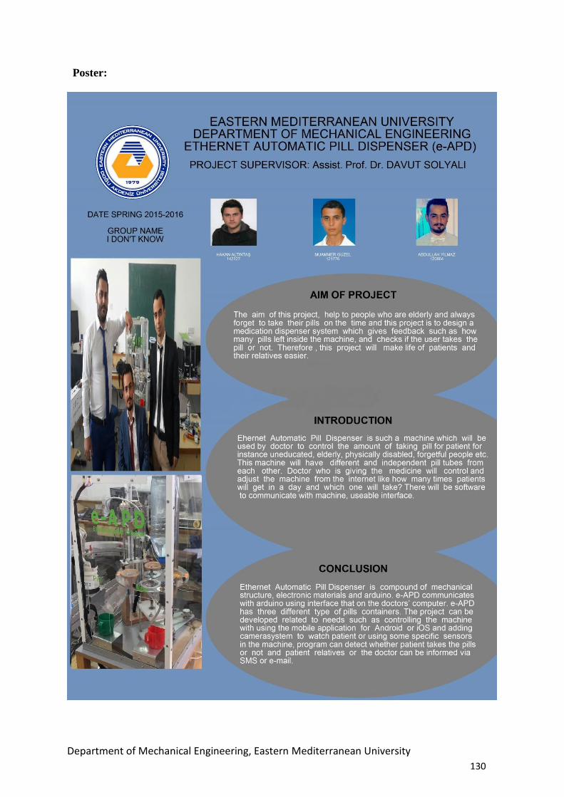
Department of Mechanical Engineering, Eastern Mediterranean University
130
Poster: