MECHANISMS AND MODES FOR IGNITION OF LOW-VOLTAGE PVC · PDF fileMECHANISMS AND MODES FOR...
19
Citation: Babrauskas, V., Mechanisms and Modes for Ignition of Low-Voltage PVC Wires, Cables, and Cords, pp. 291-309 in Fire & Materials 2005, Interscience Communications Ltd., London (2005). 291 MECHANISMS AND MODES FOR IGNITION OF LOW-VOLTAGE PVC WIRES, CABLES, AND CORDS Vytenis Babrauskas, Ph.D. Fire Science and Technology Inc., 9000 – 300 th Place SE, Issaquah WA 98027 ABSTRACT PVC is the most common insulation material used for wiring in low-voltage (LV) service. “Low-voltage,” in the context of this paper, is taken to be 120 – 240 VAC. “Wiring” is taken to include not only insulated wires, cables, or cords, but also the appurtenant termination devices, e.g., male plugs or female taps. Well-known factors leading to the ignition of PVC wiring include: (a) manufacturing defects; (b) grossly excessive current; (c) over-insulation, sometimes augmented by overcurrent; (d) localized heating due to strand breakage; (e) localized heating due to mechani- cal strand severing by staples or nails; and (f) localized heating due to failed terminations. Other failure modes are known but have received only limited study. These include (i) excessive force and creep; (ii) chemical interaction effects; and (iii) breakdown under voltage surge conditions. Additional research is needed in these areas. The proximate cause of ignition involved with many of the above mechanisms is arc tracking (arcing across a carbonized path). In turn, it is shown that PVC is especially susceptible to becoming charred, it requiring only approximately 160ºC for the material to become semiconducting during short-term exposure (around 10 h), while longer-term exposure (around 1 month) may cause failures at temperatures as low as 110ºC. Some limited data exist which suggest that standard UL and IEC temperature classifications are unduly optimistic, as applied to PVC. Mains-connected electrical appliances need to be designed to resist 6000 V surge voltages, even though this is not mandated in most of the current UL standards. Data are presented showing that the IEC 60112 wet-tracking test gives especially misleading results for PVC and should be improved or abrogated. Keywords: arc tracking, dielectric strength, electric cords, electric wires and cables, electrical fires, ignition, PVC, voltage surges. INTRODUCTION PVC and polyethylene are the two main polymer types used for wire and cable insulation, with PVC comprising about 2/3 of the insulation used for building wiring in the US 1 . Apart from wires and cables, PVC is also commonly used as the insulator in other electrotechnical products, such as plugs and connectors. PVC insulation in electrical cables for use in 120 VAC applications typically comes in thicknesses of 0.4 – 1.2 mm. For a typical formulation of PVC, test results sug- gest that such thicknesses could withstand voltages of 3 – 14 kV. Since the peak voltage corre- sponding to 120 volts rms (root-mean-square) is 170 V, it would at first seem that a huge safety factor is built in and that failure is most unlikely. As was earlier pointed out by this author 2 , the reliability of any one electrical device is extraordinarily good, but large numbers of fires of electri- cal origin occur each year in the US because an immense number of electrical devices are in use. The electrical engineering community has studied in detail, for roughly a century, failures of elec- tric insulation and devices containing electric insulation. But the vast majority of this effort has been devoted solely to high-voltage (HV) applications. Thus, these results are only indirectly—if at all—applicable to 120 – 240VAC installations. Furthermore, PVC is a polymer which is not par-
Transcript of MECHANISMS AND MODES FOR IGNITION OF LOW-VOLTAGE PVC · PDF fileMECHANISMS AND MODES FOR...

Citation: Babrauskas, V., Mechanisms and Modes for Ignition of Low-Voltage PVC Wires, Cables, and Cords, pp. 291-309 in Fire & Materials 2005, Interscience Communications Ltd., London (2005).
291
MECHANISMS AND MODES FOR IGNITION OF LOW-VOLTAGE PVC WIRES, CABLES, AND
CORDS
Vytenis Babrauskas, Ph.D. Fire Science and Technology Inc., 9000 – 300th Place SE, Issaquah WA 98027
ABSTRACT PVC is the most common insulation material used for wiring in low-voltage (LV) service.
“Low-voltage,” in the context of this paper, is taken to be 120 – 240 VAC. “Wiring” is taken to include not only insulated wires, cables, or cords, but also the appurtenant termination devices, e.g., male plugs or female taps. Well-known factors leading to the ignition of PVC wiring include: (a) manufacturing defects; (b) grossly excessive current; (c) over-insulation, sometimes augmented by overcurrent; (d) localized heating due to strand breakage; (e) localized heating due to mechani-cal strand severing by staples or nails; and (f) localized heating due to failed terminations. Other failure modes are known but have received only limited study. These include (i) excessive force and creep; (ii) chemical interaction effects; and (iii) breakdown under voltage surge conditions. Additional research is needed in these areas. The proximate cause of ignition involved with many of the above mechanisms is arc tracking (arcing across a carbonized path). In turn, it is shown that PVC is especially susceptible to becoming charred, it requiring only approximately 160ºC for the material to become semiconducting during short-term exposure (around 10 h), while longer-term exposure (around 1 month) may cause failures at temperatures as low as 110ºC. Some limited data exist which suggest that standard UL and IEC temperature classifications are unduly optimistic, as applied to PVC. Mains-connected electrical appliances need to be designed to resist 6000 V surge voltages, even though this is not mandated in most of the current UL standards. Data are presented showing that the IEC 60112 wet-tracking test gives especially misleading results for PVC and should be improved or abrogated. Keywords: arc tracking, dielectric strength, electric cords, electric wires and cables, electrical fires, ignition, PVC, voltage surges.
INTRODUCTION PVC and polyethylene are the two main polymer types used for wire and cable insulation,
with PVC comprising about 2/3 of the insulation used for building wiring in the US1. Apart from wires and cables, PVC is also commonly used as the insulator in other electrotechnical products, such as plugs and connectors. PVC insulation in electrical cables for use in 120 VAC applications typically comes in thicknesses of 0.4 – 1.2 mm. For a typical formulation of PVC, test results sug-gest that such thicknesses could withstand voltages of 3 – 14 kV. Since the peak voltage corre-sponding to 120 volts rms (root-mean-square) is 170 V, it would at first seem that a huge safety factor is built in and that failure is most unlikely. As was earlier pointed out by this author2, the reliability of any one electrical device is extraordinarily good, but large numbers of fires of electri-cal origin occur each year in the US because an immense number of electrical devices are in use. The electrical engineering community has studied in detail, for roughly a century, failures of elec-tric insulation and devices containing electric insulation. But the vast majority of this effort has been devoted solely to high-voltage (HV) applications. Thus, these results are only indirectly—if at all—applicable to 120 – 240VAC installations. Furthermore, PVC is a polymer which is not par-

292
ticularly common in HV applications, so even HV data for failures and ignitions with PVC is rare. Nonetheless, by examining worldwide efforts in this subject, especially work in Japan, it is possi-ble to formulate some principles governing the causes of fires originating from PVC-insulated wir-ing or devices. It is the purpose of this paper to provide such an initial effort.
PVC IN ELECTROTECHNICAL PRODUCTS When PVC is used for wire/cable insulation, it is not used as a pure polymer. Since intrin-
sically PVC is a rigid material and wire/cable insulation must be flexible, there has to be a signifi-cant loading of a plasticizer. Wickson3 indicates that typical wire/cable formulations contain 52 – 63% PVC resin, 25 – 29% plasticizer, around 16% filler (but occasionally as low as 5%), 2 – 4% stabilizer, 0.2 – 0.3% wax, and small amounts of lubricants and colorants; occasionally an FR agent is also included. Antioxidants are also often included in small amounts (less than 0.1%). The plasticizer is typically either a phthalate (e.g., diisodecyl phthalate, ditridecyl phthalate) or a trimellitate, e.g., tris(2-ethylhexyl) trimellitate, while CaCO3 and kaolin are common fillers. In re-cent years, formulations also commonly include a costabilizer, typically zeolite (the hydrated, so-dium Type A variety) which also functions as an HCl absorber, taking over that role from conven-tional fillers. The plasticizers are chosen according to the needed service temperature; dioctyl phthalate has been the most popular plasticizer for 60ºC-rated formulations, but US manufacturers no longer use it due to EPA reporting requirements.
CHEMISTRY OF PVC DEGRADATION PVC is one of the simpler commercially-used polymers. Thus, its basic degradation chem-
istry has been studied at some length. The problem is that most studies have been done only on pure PVC and, for PVC used in electrotechnical products, close to 50% of the mass may comprise various additives. These additives, especially stabilizers, can be expected to have an effect on the material’s degradation. Thermal degradation of PVC is a two-stage process4. As the temperature of a sample is raised above ambient, the initial mechanism is dehydrochlorination, whereby HCl molecules are released, and a polyunsaturated material is left which is sometimes referred to as polyacetylene (Figure 1). A number of studies on pure PVC5 have shown that measurable amounts of HCl are evolved by the time that 100ºC is reached; a measurable mass loss rate was found in one study6 at 78ºC in a nitrogen atmosphere. Wolter et al.56 report that, while the process can commence at a low temperature, there is an ‘induction period’ involved, in other words, that a sig-nificant interval elapses after subjecting the material to a sufficiently high temperature, before evo-lution of HCl actually begins. But other studies7 have shown that at 180ºC or higher, the induction period for unstabilized PVC is nil. More important is the performance of PVC wire/cable insula-tion, not PVC as a pure polymer. Van Luik8 studied the production of sub-micron particles and found that PVC wire insulation produced “large numbers” of these by the time that 143ºC was at-tained. Hirschler9 tested in air a flexible-PVC compound used for wire/cable making and found essentially no HCl emission at 90ºC, with measurable emissions occurring at 105ºC, which is broadly similar to the temperature range found for pure PVC. Other investigators examining simi-lar PVC wire/cable materials reported higher degradation temperatures, presumably due to use of experimental techniques not well-suited to lower temperature regimes. Chandler et al.10 found 260ºC, while Armstrong et al.11 found 240ºC for an already-aged NM cable. For pure PVC, one study12 showed that dehydrochlorination was essentially completed by the time that 250ºC was reached; another study5 showed a peak at 250ºC, while two other studies13,14 found that a peak value at about 285ºC, thus, the exact temperature range is clearly test-condition de-pendent. But for flexible wire/cable compounds, dehydrochlorination extends into higher tempera-tures, with one study10 showing the reac-tion is not completed until 360ºC is reached. The second-stage of the pyroly-sis process takes place over about 350 – 500ºC and is considered to involve sev-eral parallel reactions4. These include13 polyenyl macroradical production, dehy-
... CH CH CH CH CH
H ClClH
CH CH CH ...
H ClClH
... CH CH CH CH CH CH CH CH ... + 4HCl
Figure 1 Dehydrochlorination—the initial step in the thermal degradation of PVC

293
drocyclization, aromatization, and chain scission. At the end of the process, a cross-linked, charred residue remains. Even for pure PVC, understanding and modeling its thermal degradation is com-plicated by the fact that initiation sites for dehydrochlorination are dominated by structural abnor-malities and cannot be predicted from a representation of an ideal polymer15. The dehydrochlorina-tion is autocatalytic16, i.e., the presence of HCl gas promotes the reaction. Consequently, PVC formulations for wire/cable insulation use CaCO3 or a similar filler to act as an HCl ‘scrubber.’ Pure PVC could not be formed into useful products, since its thermal degradation generally starts below the temperature at which molding or extruding would be performed. Consequently, in commercial PVC formulations, stabilizers are added to counteract thermal degradation, to inacti-vate the HCl that is produced, and thus to reduce the autocatalytic reaction acceleration. Yet, their chemical mechanisms of action are only poorly known21. Montaudo and Puglisi17 showed that sta-bilizers raise the temperature at which significant HCl evolution commences. Mizuno et al.18 found that, compared to a (non-commercial) formulation of PVC that was not stabilized, a lead-based stabilizer raised the degradation onset temperature by roughly 30ºC. But Alvares et al.19 ran some tests where samples were tested in air, not nitrogen, and actual wire insulation was tested and compared to pure PVC. In their studies, pure PVC showed the onset of dehydrochlorination at 220ºC, but some PVC materials taken from actual electrical cords and cables showed an onset at very low temperatures, e.g., 60ºC for an appliance cord, 60ºC for a high-voltage cable, and 80ºC for a signal cable. In all cases studied, the onset of dehydrochlorination in PVC from actual cords and cables was either similar to that in pure PVC, or substantially lower. Plasticizers generally have an adverse effect on PVC stability20 and perhaps in actual wire/cable products this contribu-tion dominates. A number of studies on the effect of temperature on mechanical properties of PVC are available; typical results39 are that detectable degradation is observable if about 120ºC is reached, but such results are hard to relate to ignition or electrical failure. In many cases, loss of plasticizer is likely to occur at only moderate temperatures. Excessive loss of plasticizer will cause embrittlement, which can lead to cracking, but no study appears to have been done to examine electrical failure in this context. For a PVC plasticized with DOP, one study21 showed that a 30-h exposure at 100ºC resulted in a loss of 30% of the plasticizer, demon-strating that DOP is usable as a plasticizer only in 60ºC-rated cables and not in ones of higher rat-ings. Mann22 ran experiments on wire insulation and found that significant amounts of plasticizer were volatilized already at 85ºC. On the basis of this, he concluded that a special hazard exists when the PVC-insulated product is in an environment where the degradation products cannot be readily dissipated—in such cases, rapid burning may be anticipated that is not envisaged in the open-air test geometry of the UL 9423 test. Anandakumaran and Stonkus24 studied plasticizer loss in commercial PVC cables and found that about 25% was lost by heating at 120ºC for 70 days, or at 130º for 24 days. By contrast, a field study on 18-year old HV PVC cables showed that these had sustained only around 2% plasticizer loss25. These were outdoor cables but evidently had not suffered significant overheating or other stresses during their lifetime. The study also found that only about 20% of the lead stearate/lead phthalate stabilizer had been reacted (chlorinated). Zaikov et al.26 pointed out that loss of plasticizer causes formation of voids in the material and, as dis-cussed above, formation of voids will reduce the breakdown strength of the insulation. Both UL and IEC assign electrical insulation materials into temperature classes on the basis of 50-year old research27, and PVC can be rated up to 105ºC. But Stricker28 noted that “although cable life has not been defined, a life expectancy of 20 to 50 years is reasonable” and then ran short-term aging tests on 90ºC and 105ºC rated PVC-insulated cables. The specific products tested were heat-ing cables, thus, adequate lifetime under elevated temperature conditions was presumably a design objective. Eight different types were tested, some without jackets, others with PVC or nylon jack-ets. Significant plasticizer loss occurred for all types when held at 71 – 77ºC for approximately 1 month. Stricker interpreted the plasticizer loss as the end of useful life for the cables, although fur-ther electrical or chemical testing was not done. He concluded that none of the 90 or 105ºC-rated specimens should be operated at over 71ºC.

294
IGNITION TEMPERATURE OF PVC Ignition temperature is a concept which is primarily useful for considering ignition from
external heating sources, not due to effects of electricity. But for completeness, this will be consid-ered here briefly. The ignition temperature of pure PVC is very high, but this is not relevant to wire/cable formulations. The AIT of commercial, flexible PVC formulations reported by several authors44 spans the range of 263 – 454ºC. This is a huge range and sufficient details have not been published so that variations could be tied to specific aspects of the polymer composition. Similarly, the piloted ignition temperatures reported span the range 240 – 422ºC. The author has encountered a recent case where an exemplar of a PVC-insulated extension cord that was at the origin of a fire was found to show a very low AIT of 250ºC. This low AIT value was due to the use of a secon-dary plasticizer in the formulation. Secondary plasticizers are simple organic substances (e.g., or-dinary mineral oil, chlorinated paraffins, etc.), and are added as a cost-saving measure since they are cheaper than phthalates. Mitsuhashi et al.29 noted that ignition of wire insulation may occur from the heated metallic surface of the electrical conductor. Thus, they conducted tests according to this arrangement and obtained a hot-surface ignition temperature of 550ºC. In general, ignition of PVC wires/cables will occur due to electrical mechanisms at much lower temperatures than those needed to ignite the polymer in the absence of electric current and these studies are consid-ered below.
CAUSES OF FAILURE OR IGNITION OF PVC-INSULATED ELECTRICAL DEVICES The major causes leading to failure and possible ignition of PVC-insulated, current-
carrying products are shown in Table 1. Many of these have been examined in the Ignition Hand-book44, but the present paper extends that work by examining additional factors and mechanisms. Table 1 also indicates which failure modes are likely to be the outcome of manufacturing defects, versus poor installation or utilization practices. For a number of failure types, both may need to be considered, before ruling one of them out. Extrusion faults The most common extrusion fault is operating at an incorrect temperature. There is only a narrow range of temperatures at which a particular PVC formulation can be successfully extruded; too low a temperature will result in a non-homogeneous mixture, while too high a temperature will lead to micropores being formed35. PVC cable is subjected by the manufacturer to high-voltage break-down testing as part of the production process. For example, UL 6230 and UL 158131 require that a ‘spark’ test be part of the manufacturing process. But manufacturing defects may fail to be de-tected and emerge as a cause of fire. There has been little published on this topic and the author is aware of only a single statistical study. In that study, Hirschler32 tested a number of products pur-chased from retail channels which were manufactured in Asia, but containing listing labels claim-ing compliance to UL standards. Of 6 sets of Christmas tree lights, he found that 50% did not meet the 105ºC requirement, while 33% of 9 appliance cords tested also failed to comply. The simplest way of producing power cords and extension cords is by means of a single extrusion step, whereby the final product is formed directly. But in recent years, some manufacturers have found that more reliable cords can be produced by non-integral extrusion33. With the latter scheme (e.g., UL types NIPST-1 or NIPST-2), the insulation on the individual conductors is extruded first. Then, as a second step, an outer layer of polymer is extruded on top of the already-insulated con-ductors. This technique reduces the failure rate because, at any particular location, any manufactur-ing defects (e.g., voids) are likely to be confined to only a single conductor and not span from con-ductor to conductor. This principle, of course, is always used in non-metallic cables for building wiring (e.g., NM-B), where a separate jacket (and possibly an intermediate sheath layer) surround the wire insulation. Dielectric breakdown of PVC Dielectric breakdown causes a high-temperature arc to propagate through a dielectric medium and this can lead to ignition of the medium (if it is combustible) or of surrounding objects. Arc tem-peratures44 are in excess of 6500 K, which is higher than any combustible material’s ignition tem-perature, but arcing does not necessarily guarantee an ignition. In many cases, however, the mate-

295
rial may be ablated without ignition. In such cases, as discussed below, dielectric breakdown may initially only form a carbonized path, with ignition occurring later due to an arc-tracking process. Dielectric strength values of PVC. Under idealized circumstances, polymeric insulations can with-stand exceptionally high voltages impressed across them. The voltage required for an insulator to
Table 1 Causes leading to failure or ignition of PVC-insulated electrotechnical products
Cause Manu-facturing
defect
Poor installation or
utilization practice
Reference
Errors in formulation. Excessive filler, incompatible plasti-cizer, improper stabilizer, etc.
Refs. 3,34,35
Extrusion faults. Wire not in center of insulation, thin spots, agglomeration of ingredients, polymer improperly fused, voids, air bubbles.
Refs. 3,34,35 and here
Contamination. Refs. 3,34 and here
Entrapment of moisture. PVC itself is not hygroscopic but some additives, especially ones to create black-color PVC, are hygroscopic and trapped moisture can lead to porosity forma-tion.
Refs. 3,34 and here
Grossly excessive current. All indications are that this is a rare cause of electrical fires, since it requires both a gross overload and an improperly-sized or malfunctioning circuit-interruption device. Generally, sustained current of 3 – 7 times the rated capacity is required.
Ref. 44 p. 779
Over-insulation, possibly exacerbated by overcurrent. The ampacity rating of cables and cords is based upon certain as-sumptions of available convective cooling. This can be de-feated by the user, e.g., by burying the cable in thermal insula-tion or by using a cord reel without unspooling.
Ref. 44 p. 780
Localized heating due to severing of conductors by staples or nails. If the current has to flow through a nail or staple, a poor connection (copper to fastener) will be involved and this has been demonstrated to be a competent source of ignition.
Ref. 44 p. 790
Localized heating due to strand breakage. The so-called “last strand” problem has been studied extensively, both experi-mentally and theoretically. Laboratory studies suggest that ignition typically requires the last strand to break and that ignition is unlikely if multiple unbroken strands still remain. However, ignition is also possible if the last strand breaks, but then (poor) contact is made between the broken ends. Strand breakage normally occurs due to mechanical abuse.
Ref. 44 p. 788
Failed terminations. This is a common cause of electrical fires. Each conductor must necessarily terminate at each end. If any of these connections are poor (high resistance), a fire can result due to excessive heating at the connection. A poor connection may be a manufacturing defect, e.g., a bad crimp connection. It may also occur due to abuse or faulty installa-tion, e.g., improperly tightened screw connections, or male plugs damaged due to excessive hot-plugging.
Ref. 44 p. 549
Dielectric breakdown of PVC. Here Arcing across a carbonized path. Here Creep of insulation. Here Chemical interaction effects. Here Voltage surges. Here

296
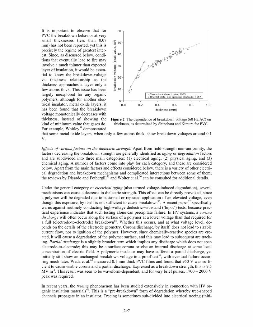
break down is a function of its thickness. In many cases, there are regimes where the breakdown voltage increases linearly with the insulator’s thickness, in such cases, results are usually reported as a breakdown strength, or dielectric strength, which has the units of volts per meter. Using test-ing devices36 with specially-shaped electrodes that minimize electric field non-uniformities and corona-provoked arc initiation, a handbook value of “intrinsic breakdown strength” can be ob-tained, which for PVC at room temperature37, is around 350 MV m-1. Such values represent an ideal-case upper limit, not an actual breakdown voltage that might be expected under in-use condi-tions. Actual breakdown, even for short-term conditions, is vastly lower than values obtained in such idealized measurements. This is both because real service conditions entail a non-uniform electrical field and because very carefully prepared specimens are used for this testing that are free of voids and other defects. Much lower values of “actual dielectric strength” are reported when commercial materials are tested with electrodes more representative of end-use conditions. ASTM D 14938 is the most commonly used test standard under AC conditions. The standard does not con-stitute a unique protocol for testing but contains three methods, a short-term test and two tests of longer duration. In addition, a wide variety of electrodes may be used, but these do not include the specialized electrode shapes used to obtain ‘intrinsic’ strength values. For wire-insulation PVC formulations, values reported by this test18,39,40 are typically 600 – 900 V/mil (24 – 36 MV m-1). Test results also depend on the details of the waveform applied. For example, in one set of experi-ments41, an 0.05 mm thick PVC film required 11.5 kV for partial-discharge breakdown using a 1 kHz sinusoidal waveform, but only 4 kV at 60 kHz. Shinohara and Kimura47 found that the break-down strength of PVC under DC conditions was almost exactly 2× times that at 60 Hz. In addition, it must be taken into account that PVC, as used in electrical insulation, contains numerous addi-tives and that these affect the breakdown strength. The effect of plasticizer concentration was studied by Shinohara and Kimura46, who found, for three different plasticizers, that if the loading was raised from 60 pphr to 100 pphr, the breakdown strength decreased by 20 – 40%. The normal fillers used in PVC have an adverse effect42. For example, tests with ASTM D 149 using 0.5 – 0.75 mm thick specimens showed a dielectric strength of 12 – 50 MV m-1 (300 – 1000 V/mil) for un-filled, flexible PVC38, but this is reduced to 8 – 12 MV m-1 (200 – 300 V/mil) when a CaCO3 filler was used3. The reduction in dielectric strength is basically because the filler is not dispersed on a molecular scale and consequently acts to disrupt the dielectric. Stabilizers also affect the break-down strength, although systematic studies are not available. Though lower than ‘intrinsic’ values, such test results may still not describe actual field performance—Whitehead43 considers that a use-ful “working stress” for PVC is only 3 – 4 MV m-1. Handbook values cited above would imply that the dielectric strength is independent of thickness. For gaseous dielectrics, Paschen’s Law shows that there is a near-constant dielectric strength (ex-pressed as MV m-1) for sizable thicknesses, but as the electrode separation is made very small, the dielectric strength rises, so that actual breakdown voltage shows a minimum at some small, but finite gap size44. Surprisingly, the thickness effect has not been well explored for solid insulators, including plastics of any type. Bartnikas36 claimed that plastics show a relation where the break-down voltage scales with the square root of thickness, but his paper provides no data on this; on the other hand, Oakes45 found that polyethylene follows a linear law for DC, but a square-root law for AC. Only two sets of data could be found for PVC. The results of Shinohara et al.46,47 are shown in Figure 2. Their 1955 tests used two spherical electrodes and show a square-root depend-ence. Their 1957 experiments were done using one flat-plate electrode and one spherical electrode; these tests encompassed a narrower range of thicknesses and the results show a linear dependence. While electrode shape is the obvious experimental difference between the two sets of results, ex-amination of data in the literature on other solid insulation materials39,48-52 does not support the hy-pothesis that electrode shape is the experimental variable which determines if the relation is linear or square-root. The other study is by Abed53, but he only studied samples of ≥ 0.5 mm thickness. At the extreme, if the thickness is made very large, eventually failure of a solid insulator will occur due to thermal breakdown, and the latter is thickness-independent. This is not relevant to the pre-sent topic because for PVC the voltage necessary for thermal breakdown is around 100 kV.
297
It is important to observe that for PVC the breakdown behavior at very small thicknesses (less than 0.07 mm) has not been reported, yet this is precisely the regime of greatest inter-est. Since, as discussed below, condi-tions that eventually lead to fire may involve a much thinner than expected layer of insulation, it would be essen-tial to know the breakdown-voltage vs. thickness relationship as the thickness approaches a layer only a few atoms thick. This issue has been largely unexplored for any organic polymers, although for another elec-trical insulator, metal oxide layers, it has been found that the breakdown voltage monotonically decreases with thickness, instead of showing the kind of minimum value that gases do. For example, Whitley54 demonstrated that some metal oxide layers, when only a few atoms thick, show breakdown voltages around 0.1 V. Effects of various factors on the dielectric strength. Apart from field-strength non-uniformity, the factors decreasing the breakdown strength are generally identified as aging or degradation factors and are subdivided into three main categories: (1) electrical aging, (2) physical aging, and (3) chemical aging. A number of factors come into play for each category, and these are considered below. Apart from the main factors and effects considered below, there is a variety of other electri-cal degradation and breakdown mechanisms and complicated interactions between some of them; the reviews by Dissado and Fothergill55 and Wolter et al.56 can be consulted for additional details. Under the general category of electrical aging (also termed voltage-induced degradation), several mechanisms can cause a decrease in dielectric strength. This effect can be directly provoked, since a polymer will be degraded due to sustained or repeated application of an elevated voltage, even though this exposure, by itself is not sufficient to cause breakdown36. A recent paper57 specifically warns against routinely conducting high-voltage dielectric-withstand (‘hipot’) tests, because prac-tical experience indicates that such testing alone can precipitate failure. In HV systems, a corona discharge will often occur along the surface of a polymer at a lower voltage than that required for a full (electrode-to-electrode) breakdown58. Whether this occurs, and at what voltage level, de-pends on the details of the electrode geometry. Corona discharge, by itself, does not lead to sizable current flow, nor to ignition of the polymer. However, since chemically-reactive species are cre-ated, it will cause a degradation of the polymer surface, and this may lead to subsequent arc track-ing. Partial discharge is a slightly broader term which implies any discharge which does not span electrode-to-electrode; this may be a surface corona or else an internal discharge at some local concentration of electric field. A polymeric insulator may have suffered a partial discharge, yet initially still show an unchanged breakdown voltage in a proof test59, with eventual failure occur-ring much later. Wada et al.60 measured 0.1 mm thick PVC films and found that 950 V was suffi-cient to cause visible corona and a partial discharge. Expressed as a breakdown strength, this is 9.5 MV m-1. This result was seen to be waveform-dependent, and for very brief pulses, 1700 – 2000 V peak was required. In recent years, the treeing phenomenon has been studied extensively in connection with HV or-ganic insulation materials61. This is a “pre-breakdown” form of degradation whereby tree-shaped channels propagate in an insulator. Treeing is sometimes sub-divided into electrical treeing (initi-
0
10
20
30
40
50
60
0.0 0.2 0.4 0.6 0.8 1.0
Thickness (mm)
Bre
akdow
n v
oltag
e (p
eak
valu
e, k
V)
Two spherical electrodes: 1955One flat plate, one spherical electrode: 1957
Figure 2 The dependence of breakdown voltage (60 Hz AC) on
thickness, as determined by Shinohara and Kimura for PVC

298
ated by partial discharges), water treeing, or chemical treeing (due to reactions with other contami-nants). The growth of trees requires an electrical field to be impressed across the insulators, but various factors affect the process, including manufacturing defects, and contamination. Mechanical stress also affects treeing, but only tensile stresses promote treeing—compressive stresses retard it62. The diminution of resistance to treeing is particularly notable if a polymer contains initial stresses, due to the molding or extruding process63. A partial discharge will, of course, create a tree. Additives and fillers also affect treeing; plasticizers reduce the resistance to treeing, while inert ‘barriers,’ such as grains of filler, increase it64. Some stabilizers are specifically used to im-prove resistance to treeing65. Treeing has generally attracted interest only of the HV engineering community, although Kawawata and Ogura66 conducted a study after an incident where a 600 V underground cable failed which had polyethylene wire insulation, but a PVC outer jacket. They found that the conductors contained a “rust” comprised of cupric sulfide (CuS) along with smaller amounts of other contaminants. Even though lead-based stabilizers have a low solubility in water, the authors concluded that the reaction started with aqueous contaminants reacting with the stabi-lizer, traveling through the polyethylene wire insulation, and leaching out as lead sulfide; hydrogen sulfide was also involved in this sequence. Experiments using a 100 V power supply were able to elicit very substantial development of insulation treeing due to chemical attack. Once chemically initiated, despite the low supply voltage, pervasive treeing was able to occur because, locally, the electric field was very high due to the irregularity represented by the tree. The authors calculated that, at the tip of the tree, the local field was 2600 MV m-1. Treeing due to presence of water is called water treeing and generally requires65 that the polymer be in an atmosphere over 70% RH. Real-life insulating materials are likely to contain voids. In such case, breakdown will normally occur at a defect site and under lower voltage than would have been required for a defect-free specimen36. This is due to a combination of two factors: (a) air has a lower breakdown strength than polymers; and (b) presence of a void creates local electric field strength irregularities, with the lower permittivity of air causing an intensification of the electric field at the solid/void interface. Consequently, breakdown will preferentially occur first at a solid/void interface. An initial break-down (a partial discharge) has the consequence of disrupting the polymer structure and increasing the void size; thus the process can lead to runaway breakdown. There are some data to suggest that voids, by themselves, will not rapidly lead to catastrophic breakdown67 unless their size is at least 0.1 mm; for larger voids, the discharge changes its character from a Townsend discharge to a streamer discharge, with the latter being much more damaging to the polymer. Partial discharges will occur at a lower voltage when there is a void or damage within the insulator, but only limited data are available for PVC. Apart from manufacturing defects, oxidative embrittlement can lead to formation of voids as an aspect of polymer degradation and aging67, but data on PVC are lacking. Conductor irregularities will lower the measured dielectric strength in testing36; again, data on PVC are absent. A mechanical stress that is applied for a prolonged period of time leads to physi-cal aging of a polymer. This aging is manifested in two ways: (1) by causing formation of polymer radicals56; and (2) as an increase in the number and size of microvoids in the material55. Both of these consequences lower the dielectric strength of the materials, although quantitative data on PVC are lacking. There is sometimes considered to be a synergistic interaction between mechani-cal stress and applied voltage as factors promoting polymer degradation or failure. Chemical degradation is caused by formation of free radicals which leads to bond-breaking or un-zipping of the polymer structure. The process can be initiated by thermal or mechanical means, by oxidizing reactions, by hydrolysis, or by UV or ionizing radiation. Polluted environments may cause a direct attack upon a polymer. This has been studied in the context of atmospheric pollution and strong industrial acids/alkalis, but studies applicable to PVC have been limited. For many plas-tics used in electrical insulation, oxidative pyrolysis is accelerated by metals68. Minute metallic contaminant inclusions can cause “extreme oxidative degradation”69, and such metallic contami-nants can act to produce initiation sites for electrical treeing55. Wolter et al.56 specifically point out the deleterious impact of zinc dust on PVC. Even quite small amounts of moisture introduced in processing PVC can cause mechanical failure and this can lead to electrical failure69. One might anticipate that antioxidants could improve the breakdown strength of a polymer, but studies on

299
polyethylene45 showed that, in fact, they act as an impurity and reduce the strength—a 1% add-on caused a 16% drop in breakdown strength; similar studies for PVC are not known. Elevated temperatures reduce the breakdown strength of PVC. This relation is controlled by the amount (and type) of plasticizer used. Without a plasticizer, PVC shows a slightly rising break-down strength up to 70ºC, then drops precipitously46. Using 30 pphr dioctyl phthalate (DOP), the peak is reached at 20ºC, while at 100 pphr DOP, decline starts below room temperature. For the composition using 30 pphr DOP, the breakdown strength at 80ºC (the highest temperature studied) dropped to 40% of that at 20ºC. If failure is primarily caused by corona discharges on the surface, raising the humidity decreases the propensity to failure, since high humidity interferes with the co-rona discharge process. But the effect of high humidity is more likely to be an adverse effect on arc tracking, as indicated below. Arcing across a carbonized path Energized devices can ignite if a carbonized path (arc tracking) spanning between conductors comes to exist. A carbonized path may be caused by many means, including failed terminations and inappropriate external heating. The conditions where the carbonized path is created by electric current activity (as opposed to external heating) are described as dry tracking or wet tracking44. If moisture is not involved, then inducing arc tracking normally requires that the polymer be sub-jected to an elevated temperature. The temperature required to establish carbonization of PVC is low: Japanese studies showed44 that about 160ºC suffices during short-term tests, and specimens were able to reach ignition under those conditions. For long-term exposures, Stricker’s study, dis-cussed above, implies that failure might be expected at temperatures as low as 71ºC, although his experiments were not carried to the point of ignition. Alumina trihydrate (Al2O3·3H2O) is a filler/FR agent which would improve the tracking resistance80, however, only specialty PVC for-mulations (flame retardant, low-smoke) use this filler. Wet tracking can take place if a path between two conductors is established which contains a water film. This can readily happen if connections are exposed to a wet environment, but bulk cable normally requires that insulation be stripped off a section, exposing both conductors. Since con-duction of an electric current along the surface of a polymer is the way in which wet tracking is initiated, high-RH environments may thus lead to failure that otherwise would not occur. If the RH increases to 100% and liquid water begins to condense on the surface, conditions favorable to arc tracking are even further enhanced. Published ratings on PVC imply that it is good at resisting wet-tracking, although it is in the worst category for resistance to dry-tracking. But unfortunately, research studies have shown that the good wet-tracking results are an artifact of the IEC 60112 test, and not an indicator of actual per-formance. For dry-tracking, Wilkins and Billings70 found in their pioneering study that PVC was the worst polymer for dry tracking, of all the polymers they studied. Similarly, Sommerman71 ran the standard ASTM D 495 test for dry-tracking and found PVC to be tied for last place, among 14 plastics studied. When tested under the standard IEC 60112 test for wet-tracking, however, it is easy for PVC to achieve the highest rating, CTI ≥ 600 V, as documented by Suhr72. The standard does not use volt-ages over 600 V, but one study found73 that values of 900 – 950 V would be reported using the IEC 60112 method, were it to use higher test voltages. The problem is that the IEC test is not run on cables at all, but on flat plaques, with the voltage being supplied to two oblique electrodes placed against the surface. Several studies examined the more realistic situation of an actual cable where a section of insulation was scraped away to expose the two conductors, with voltage being supplied through the conductors themselves (Figure 3). Kawamura et al.74 conducted tests on Japa-nese 600-V rated PVC cables (VVF type) using a 100 V power source and were readily able to elicit scintillation and subsequent arcing. Similarly, Oba75 ran tests on VVF cables using a similar test geometry and was able to obtain tracking down to about 24 V, although the extent of tracking was limited for voltages below 50 V. Even the test electrode material in the IEC 60112 test is in-

300
appropriate. Platinum is specified, al-though copper is by far more likely to be the conductor in real-life situations. Suhr72 found that running the test using copper electrodes gives significantly lower CTI values than using the man-dated platinum ones. Simply changing the electrode in the IEC 60112 test would not make it adequate, however. A recent UL study76 found that PVC was still in-appropriately ranked in the ‘best’ cate-gory using a modified test with copper electrodes. Many PVC compositions contain CaCO3 as a filler. In such cases, under initially-dry conditions, but modestly elevated temperatures, this filler actually induces a surface wetting which, in turn, can lead
to wet tracking. In one study77, it was found that this effect did not take place at 120ºC, but did oc-cur at 165ºC; intermediate temperatures were not studied. But Ohtani and Kawamura78 heated commercially-available PVC plugs in an oven at 110 – 120ºC for 10 days. The plugs contained 20 mass% CaCO3. After this heating, the plugs were returned to a room-temperature atmosphere and the resistance between the blades monitored. Figure 4 shows that failure did not occur during the heating, since 24 h after this treatment, the resistance still averaged 6 MΩ. But over subsequent days, the resistance dropped monotonically until it fell to 850 Ω at 15 days. The latter value is low enough that ignition due to current flow over the insulation would result. The authors conducted additional tests and showed that failures would not have occurred, had CaCO3 not been present in the formulation. Taken together, these two studies indicate that normal commercial PVC formula-tions are likely to fail rapidly by self-induced, wet arc tracking if 165ºC is reached, and after a sub-stantial delay if 110 – 120ºC is attained. The ability of HCl to promote corrosion may be an additional factor in the arc-tracking failure of PVC-insulated wiring. Kawamura et al.79 conducted experiments showing that an NH4Cl solution applied between copper or brass electrodes created products which included Cu(OH)Cl, Cu(OH·Cl)2·2H20, and Cu2(OH)3Cl. These reaction products served to actively promote arc-tracking failure. These or similar products might also well be produced by HCl interacting with copper, as it is evolved from PVC. Fungal growth on PVC insulation can also lead to arc tracking80. Voltage surges Despite the nominally low voltage of 120 – 240 V in branch-circuit wiring, higher voltages must be expected due to surges. A surge of suf-ficiently high voltage will cause a direct break-down of the insulation. But lesser magnitudes can occur as partial discharges, which will de-grade the polymer and make it more readily prone to delayed failure. In either case, the ini-tial outcome can be that arc tracking is initi-ated, but ignition does not occur until a signifi-cant time interval has elapsed during which arc tracking damage has progressed. Investigators have long observed that some fires originating
Figure 3 Wet-tracking occurring in a PVC-insulated cable
(Japanese VVF) under realistic test conditions (Courtesy Yasuaki Hagimoto)
Time after removal from oven (h)
0 50 100 150 200 250 300 350 400
Res
ista
nce
()
102
103
104
105
106
107
108
Figure 4 Gradual failure of a PVC plug at room temperature, after being heated in an oven for 10
days at 110 – 120ºC

301
at a PVC-insulated electrotechnical product do not have an obvious explanation. It is this author’s thesis that a portion of such occurrences should be attributed to arc tracking induced by surges. In one case encountered by the author, for example, a fire originated at the female tap portion of a PVC-insulated extension cord. The cord was located in a protected area and was not normally plugged/unplugged. Investigation of exemplars revealed a manufacturing defect, in that the strain-relief portion of the tap made an especially deep indentation into the cord. This alone would not cause an electrical failure in 120 VAC service, because even a much reduced thickness of PVC insulation will withstand 120 VAC. But what must be considered is that this portion of compro-mised insulation would be prone to fail first under sufficiently severe surge conditions, with the surge causing an electrical breakdown and carbonizing the insulation. Actual ignition, however, might not occur until a substantial period of arc-track development had taken place. In a similar vein, sometimes houses have been ignited due to a lightning strike, but after a sizable delay. For example, in one case in Sweden81, fire occurred four months after lightning struck a house. Imme-diately preceding the fire, the occupants noticed various electrical anomalies in the house. The ex-planation is that the lightning strike initiated arc tracking, but overt ignition did not take place until the arc tracking had well progressed. A time lapse of two years was also reported in a similar inci-dent that occurred in Maryland82. Surges on powerlines occur from two primary sources83,84: lightning, and electrical utility equip-ment operations or failures. Into the latter category fall such events as switching of power-factor capacitors, operation of reclosers, and outright failures, e.g., a high-voltage transmission line fal-ling and hitting a lower-voltage conductor. In addition, surges can be generated by equipment or devices in any building itself. This is very common—and sometimes highly problematic—in in-dustrial premises, but is also a factor in residences. One study85 estimated that about 2.5% of US households generate surges of 1200 V or higher on a 1/day or more frequent recurrence basis. A series of experimental results on surge voltages in 120 VAC branch circuits were reported in two papers by Martzloff et al.86-88. Figure 5 shows that a reasonable representation of the data is: 7.28 /101.2 VE ×= where E = events per year and V = surge voltage (peak). Also, since a large fraction of surges are lightning-related, the frequency of severe surges shows distinct regional variations89, since the fre-quency of lightning strikes is not uniformly distributed within the US. IEEE recommends84 that locales be evaluated as low-, medium-, or high-exposure, with the high-exposure locales receiving 0.5 – 100 surges of 6000 V per year. Mansoor et al.105 point that more recent surveys indicate lower surge voltages, because many houses are now extensively protected both by dedicated surge protective devices (SPDs) and by adventitious ones. Devices such as computers or amplifiers con-taining switch-mode power sup-plies are an example of the latter, since these effectively place large surge-absorbing capacitors across the power line90. Beyond about 6500 V(rms), or 9200 V(peak), theory would indicate that flashover is expected across normal air clearances in a branch circuit. In practice, experience is that voltages in excess of 6000 V(peak) will cause numerous instances of ‘sparkover of clear-ances,’ e.g., arcing inside most of the building’s electrical outlets87. Consequently, it has been noted
0.001
0.01
0.1
1
10
100
100 1,000 10,000Peak voltage (V)
Occ
urr
ence
s per
yea
r
Breakdown over normal clearance distances
Figure 5 Surge voltages experienced in branch-circuit wiring

302
that clusters of house fires often occur after a thunderstorm91. In 1953, General Electric, which was manufacturing electric clocks, noticed that there was a large number of returns of non-working clocks. They investigated and found that this was due to the clocks’ windings getting burned out by surge voltages. They raised their manufacturing standard to go from a 2000 V withstand voltage to 6000 V. When they did this, the failure rate83,92 was re-duced by a factor of 100:1. This information that consumer electrical goods should be designed to withstand 6000 V surges without damage was already documented in an IEEE paper93 in 1970. In 1984, Bernstein89 wrote in another IEEE journal that properly designed appliances “must be able to withstand at least 3-kV voltage spikes and preferably 6-kV voltage spikes.” Despite this, a variety of electric and electronic consumer goods is manufactured with inadequate surge-voltage resis-tance. Most UL standards contain a dielectric-withstand test. As an example, the UL test for electric coffeemakers (UL 108294) requires that a sinusoidal, 1000 V(rms) overvoltage be imposed for a 60 s test time. Many UL tests, such as those for thermal cutouts (UL 102095) and electric blankets (UL 96496), impose a voltage comprising 2×120+1000 V(rms) for 60 s. For some standards (e.g., UL 58897), the requirement is nearly identical at 1250 V(rms). In all of the tests, the overvoltage is not applied as a voltage surge across the powerline. Rather, the test overvoltage is applied between each side of the line and the “dead metal” parts of the device or user-accessible external metal parts. In case the device is all-plastic, for some devices, UL’s practice is to wrap it in aluminum foil and then apply the test overvoltage between each side of the line and the wrapping foil. For electric blankets, the product is immersed in a saline solution and the overvoltage is applied be-tween line and this liquid bath. Such testing procedures may elicit some hazardous conditions of the product being tested, but obviously do not substitute for a surge voltage applied directly across the line. The newer UL standards which are IEC-derived take a slightly different approach. The standard for computer and communications equipment (UL 6095098) specifies a basic 1000 V(rms) with-stand voltage requirement for electrical insulation. Audio and video equipment (UL 6006599) are required to withstand 1410 V(peak), which is essentially identical to 1000 V(rms). These IEC-derived standards also prescribe a separate mains-overvoltage transient test, comprising four dif-ferent “levels” at which the test may be conducted. For 120 VAC-rated equipment, these levels are 800, 1500, 2500, and 4000 V(peak), but for most equipment only the 1500 V level is applied. A few UL standards (e.g., UL 217100, UL 943101, and UL 1699102) have higher requirements. For example, the UL standard for smoke detectors (UL 217) has two separate requirements for tran-sients. The basic requirement is that 120 VAC-powered units show a withstand voltage of 1414 V(peak). But this is supplemented by a 6000 V(peak) “supply line (high-voltage) transients” test. The test waveform is a decaying envelope, with a rise time < 0.5 µs and a duration of 20 µs. A to-tal of 500 pulses are to be presented, one every 10 s; the amplitude of each succeeding pulse is ½ that of the previous one. In addition, a separate test presents a series of transients encompassing 100 – 2400 V “low-voltage” range. Unfortunately, the actual loss experience is troubling. CPSC files contain a number of documented cases103 where UL-217-Listed smoke detectors spontane-ously caught fire and investigation ascribed these to voltage-surge conditions. But since none of the incidents involved whole-house sparkover of clearances, it appears most likely that the prod-ucts actually catching fire would not have complied with the required test. Different withstand-voltage requirements are prescribed by UL for wires, cords, and cables. For example, UL 6230 requires a withstand voltage of 1500 V(rms) for the SPT family of flexible cords and 2000 V(rms) for the SJ family. For other classes of wiring within the same standard, require-ments tend to increase with conductor size, going from 1000 V(rms) for 27 AWG type TPT cords, up to 4000 V(rms) for 8 AWG type E cables; in most cases, however, values around 1500 – 2000 V(rms) are mandated. For non-metallic NM cables used for building purposes, however, UL 719104 requires 5000 V(rms). The actual test conditions for NM testing are rather mild, since a sinusoidal

303
voltage is ramped up slowly at a rate of 10 to 60 V s-1 and then held for 60 s. For flexible cords, a somewhat tougher regimen is prescribed whereby the entire required withstand voltage is ramped up during a 10 – 60 s interval. For appliances, however, the slew rate is essentially uncontrolled in the standards, although it appears that in practice it is applied very slowly. Apart from the sus-tained-voltage testing regimen of the dielectric-withstand test, the UL standards for wires and ca-bles require a production-line ‘spark’ test31. The latter is typically mandated at the 6000 V(rms) level, but no scientific studies on its performance appear to have been published. A study105 has been published showing that light bulbs rated for 120 VAC service generally fail when subjected to surges of 1200 to 1500 V(peak), although if the surge occurs at the least-favorable portion of the power cycle (the peak of the sine wave), as little as 800 V suffices*. The failure voltages are directly proportional to the service voltage, with bulbs rated for a 230 VAC service voltage requiring double the surge voltage for failure106. Interestingly, the failure normally occurs not due to direct overheating of the filament from excessive current, but rather it is precipi-tated by sparkover across the still-intact filament. This arc can be on the order of 100 A and it comprises the mechanism by which the filament gets melted. Curiously, even though the separa-tion between electrodes is smaller at the support wires than at the filament itself, sparkover nor-mally does not occur at the support wires (due to the much lower temperatures in the region of the support wires). In a follow-on study by the same authors106, under some conditions of test wave-form and circuit parameters, ‘threshold’ values of 2600 V were found, with mean values not being reported. In actual practice, it is very rare to encounter situations where a building sustains simul-taneous destruction of numerous light bulbs, even though Figure 5 indicates that, in the absence of widespread use of SPDs, a household will be subjected to a 1500 V surge on a more frequent than once-yearly recurrence basis. This is because it has been found107 that once an initial bulb fails (or a few), this tends to effectively clamp the surge, preventing a massive failure. In 1990, Smith and Standler108 bought and tested a variety of mains-powered electrical consumer appliances and subjected them to surge testing. The primary waveform was one which showed a 6000 V peak, then a progressive damped decay. Their results are shown in Table 2. The micro-wave ovens contained internal surge suppression devices and these functioned properly. The linear power supplies were evidently robust enough to directly withstand the test surge. In this limited testing, there were no overt, sustained ignitions but the authors noted that in the case of the second switching power supply, an orange glow was seen and a burning odor was smelled. The documen-tation on the failures was not detailed, but it can be presumed that the failures fell into two types: overcurrent, or overvoltage. Failures of transformer windings and of AC filter capacitors are most likely due to an insufficiently high voltage rating. Conversely, opening of fuses, burning out of resistors, and disintegration of chokes is presumably due to excessive current and the situation would not have been altered had these been provided to a higher voltage rating. The statistical im-plications of the Smith and Standler study appear to be unduly optimistic, according to the experi-
* Some types of light bulbs can resist much higher voltages, for reasons not documented in the literature84.
Table 2 Performance of appliances subjected to a 6000 V test surge voltage, as tested by Smith and Standler
Appliance No. tested
No. failed
Failure mode
clock radio, or clock w/o radio 5 1 primary winding of transformer shorted out television receiver 2 2 fuse opened in one; fuse opened and ferrite core of a sup-
pressor choke broke apart microwave oven 2 0 power supply, switching 2 2 primary winding of transformer shorted out and fuse
opened in one; primary winding of transformer shorted out, filter capacitor across AC line exploded, several resis-tors burned up, and fuse opened in second*
power supply, linear 4 0 * this unit was tested with 4 kV, not 6 kV peak voltage

304
ence of the present author. Prior to the installation of a whole-house SPD, despite widespread use of local SPDs throughout the house, the author’s residence suffered roughly one incident per year where after a surge/power outage it was found that some electric or electronic device had been de-stroyed (although none led to external fire). Creep of insulation Creep is the progressive deformation of a material due to a sustained load. In plastics, it manifests as a physical aging process, common to all amorphous polymers, which consists of an ongoing vitrification process. Numerous electrical properties are affected by this, but it has been studied only to a very limited extent109. Several studies on creep of PVC have been published110,111 but none directly address electric failures. Subjecting a cord or cable to a sizable, sustained pinching force is known to be a cause of fires and the general nature of failure due to creep has briefly been reviewed44. There have not been laboratory studies, however, to examine the details of such fail-ures. The initial mechanism may involve actual strand-to-strand contact between two conductors, or simply voltage breakdown due to extreme thinness. This initial failure can cause either a self-clearing fault, or one that trips the circuit-interruption device. Upon restoration of power, the cir-cuit is likely to function, but there will now be a carbonized path that has been formed between the conductors. A fire may occur at that place after some delay. Chemical interaction effects Contact of PVC with various other plastics has been known to cause plasticizers to exude out from the PVC69; this can lead to mechanical failure of the insulation, with the potential of progressing to electrical failure. Plasticized PVC in contact with rigid plastics has also been known to lead to en-vironmental stress cracking of the stressed rigid plastic by migration of plasticizer112. Conversely, Bennett113 noted that, at elevated temperatures, if a PVC-insulated cable is in contact with polysty-rene foam insulation, phthalate-ester PVC plasticizers will dissolve the polystyrene. PVC also has been found114 to be deleterious to polyethylene—a cable construction using cross-linked polyeth-ylene (XLPE) wire insulation and a PVC jacket showed more severe thermal degradation of the XLPE than in the absence of PVC.
SUMMARY AND CONCLUSIONS PVC is a plastic which is very widely used for LV insulation. Most of the failure mecha-
nisms involving PVC are ones which are common to all polymer families. But its poor perform-ance at elevated temperatures and poor tracking performance must be taken into account when evaluating the actual field performance. The study by Stricker suggests that standard temperature classifications for electrical insulation are unduly optimistic, as applied to PVC. Commercial PVC wire/cable insulation is generally calcium-carbonate-filled, and this has a unique failure mode, in that modestly elevated temperatures (around 110ºC) can induce wet tracking, under initially-dry conditions. The wet-tracking results obtained for PVC using the IEC 60112 test are misleading and this test method should be improved or abrogated. The same applies to the nearly-identical ASTM D 3638115 and the wet-tracking provisions within UL 746A116. The breakdown strength of PVC has not been measured for very thin layers, and it would be essential to obtain this knowledge in order to better understand some of the failure mechanisms. There are essentially no studies where the time element (i.e., how long does it take for a certain condition to lead to ignition) has been quanti-fied. Several failure modes exist where knowledge of conditions leading to failure is very limited: (1) contaminants or mechanical defects introduced in the manufacturing process; (2) sustained force/creep; (3) chemical interaction effects; and (4) voltage surges. Research should be pursued in these areas. Current UL standards typically require mains-connected electric appliances to with-stand only around 1500 V surge voltages and some of these standards involve only surge testing between one side of the power line and dead-metal appliance parts. In accordance to what was learned by General Electric several decades ago, these standards should be upgraded to require resistance to 6000 V surges, and this testing should be done using a surge voltage applied directly across the powerline. A number of smoke detectors Listed under UL 217 have ignited from voltage surges, despite the 6000-V requirement present in that UL standard. Investigation should be made to determine why the UL 217 procedures do not ensure adequate surge performance. The bulk of research on fires originating from LV electrical installations has been done in Japan; it should be a

305
priority to establish competent research groups in the United States to work in this field. Finally, it should be noted that no studies could be found comparing the failure rate of LV electrotechnical products insulated with PVC, versus other types of polymers. If the latter comparison is made, it will also be necessary to compare the post-ignition, flame-spread behavior of the polymers, since the effect on fire risk cannot be properly quantified without also taking into account the post-ignition fire behavior. Acknowledgements: The review of the manuscript by John L. Allen (BATF), Günter Beyer (Kabelwerk Eu-pen AG), Anthony Bur (NIST), David A. Dini (UL), Richard Grossman, Yasuaki Hagimoto (NRIPS, Japan), Herman J. Hall, Marcelo Hirschler, François D. Martzloff, John J. Shea (Eaton Electrical Inc.), James W. Summers, Inder Wadehra, Ed Weil (Polytechnic University), and Noboru Yoshimura (Akita University) is gratefully acknowledged.
REFERENCES
1. Harriman, L., Environmental, Health and Safety Issues in the Coated Wire and Cable Industry (Tech. Report No. 51), The Massachusetts Toxic Use Reduction Institute, Lowell MA (2002).
2. Babrauskas, V., How Do Electrical Wiring Faults Lead to Structure Ignitions? pp. 39-51 in Proc. Fire and Materials 2001 Conf., Interscience Communications Ltd., London (2001).
3. Wickson, E. J., Handbook of Polyvinyl Chloride Formulating, Wiley, New York (1993). 4. Wu, C.-H., et al., Two-Stage Pyrolysis Model of PVC, Canadian J. Chem. Eng. 72, 644-650 (1994). 5. David, C., Polyvinylchloride, pp. 78-98; 169-170 in Comprehensive Chemical Kinetics, vol. 14:
Degradation of Polymers, C.H. Bamford and C.F.H. Tipper, eds., Elsevier, Amsterdam (1974). 6. Salovey, R., and Bair, H. E., Degradation of Poly(vinyl Chloride), J. Applied Polymer Science 14,
713-721 (1970). 7. Varma, I. K., and Sharma, K. K., Thermal Degradation of Poly(vinyl chloride) in the Presence of Ad-
ditives. Part I. Die Angewandte makromolekulare Chemie 71, 157-166 (1978). 8. Van Luik, F. W. jr., Characteristics of Invisible Particles Generated by Precombustion and Combus-
tion, Fire Technology 10, 129-139 (1974). 9. Hirschler, M. M., Hydrogen Chloride Evolution from the Heating of Poly(vinyl Chloride) Com-
pounds, Fire & Materials, to be published. 10. Chandler, L. A., Hirschler, M. M., and Smith, G. F., A Heated Tube Furnace Test for the Emission of
Acid Gas from PVC Wire Coating Materials: Effects of Experimental Procedures and Mechanistic Considerations, European Polymer J. 23, 51-61 (1987).
11. Armstrong, R. W., Mason, J., Kumar, A., and Hall, J. E., Thermally Induced Failure of Low-Voltage Electrical Nonmetallic-Sheathed Cable Insulation, Fire Technology 35, 263-275 (1999).
12. Gilbert, J. B., Kipling, J. J., McEnaney, B., and Sherwood, J. N., Carbonization of Polymers. I. Thermogravimetric Analysis, Polymer 3, 1-10 (1962).
13. Liebman, S. A., Ahlstrom, D. H., and Foltz, C. R., Thermal Degradation Studies of PVC with Time-Resolved Pyrolysis GC and Derivative TGA, J. Polymer Science—Polymer Chemistry Edition 16, 3139-3150 (1978).
14. Ohrbach, K.-H., Radhoff, G., and Kettrup, A., Investigations of the Thermal Decomposition of PVC Cable Material by Means of Simultaneous TG-DTG-DTA-MS Analysis, Thermochimica Acta 85, 403-406 (1985).
15. Kumar, N. N., Ageing and Stabilization of PVC Electrical Insulation – A Review, Popular Plastics (India) 27:5, 3-9 (1982).
16. Hjertberg, T., and Sörvik, E. M., On the Influence of HCl on the Thermal Degradation of Poly(Vinyl Chloride), J. Applied Polymer Science 22, 2415-2426 (1978).
17. Montaudo, G., and Puglisi, C., Evolution of Aromatics in the Thermal Degradation of Poly(vinyl chloride): A Mechanistic Study, Polymer Degradation and Stability 33, 229-262 (1991).
18. Mizuno, K., Hirukawa, H., Kawasaki, O., Noguchi, H., and Suzuki, O., Development of Non-Lead Stabilized PVC Compounds for Insulated Wires and Cables, Furukawa Review No. 18, 111-118 (1999).
19. Alvares, N. J., Lipska-Quinn, A. E., and Hasegawa, H. K., Thermal Degradation of Cable and Wire Insulations, pp. 42-66 in Behavior of Polymeric Materials in Fire (ASTM STP 816), ASTM, Phila-delphia (1983).
20. Zaikov, G. E., Gumargalieva, K. Z., Pokholok, T. V., and Moiseev, Yu. V., PVC Wire Coatings. Part 1. Ageing Process Dynamics, Intl. J. Polymeric. Materials 39, 79-125 (1998).
21. Titow, W. V., PVC Plastics: Properties, Processing, and Applications, Elsevier, London (1990).

306
22. Mann, D., private communication (2004). 23. Tests for Flammability of Plastic Materials for Parts in Devices and Appliances (UL 94). Underwrit-
ers Laboratories, Northbrook, IL. 24. Anandakumaran, K., and Stonkus, D. J., Determination of PVC Cable Insulation Degradation, J. Vi-
nyl Technology 14, 24-28 (1992). 25. Brebu, M., et al., Study of the Natural Ageing of PVC Insulation for Electrical Cables, Polymer Deg-
radation and Stability 67, 209-221 (2000). 26. Zaikov, G. E., Gumargalieva, K. Z., Pokholok, T. V., and Moiseev, Yu. V., PVC Wire Coatings. Part
II. Characterizations and Performance Predictions, Intl. J. Polymeric Materials 39, 261-288 (1998). 27. Dakin, T. W., Electrical Insulation Breakdown Treated as a Chemical Rate Phenomenon, Trans.
AIEE 67, 113-122 (1948). 28. Stricker, S., Thermal Design of PVC-Insulated Heating Cable (Report 74-26-K), Ontario Hydro, To-
ronto (1974). 29. Mitsuhashi, N., Yokoi, Y., Nagata, M., and Isaka, K., Ignition Experiments and Thermodynamic
Analysis of Model Cord with Disconnected Element Wires (in Japanese), J. Japanese Assn. for Fire Science & Engrg. 31, No. 1, 11-19 (1981).
30. Flexible Cord and Fixture Wire (UL 62), Underwriters Laboratories Inc., Northbrook IL. 31. Reference Standard for Electrical Wires, Cables, and Flexible Cords (UL 1581), Underwriters Labo-
ratories Inc., Northbrook IL. 32. Hirschler, M. M., GBH International, Decorative Lights Failing US Safety Checks, submission to
CPSC (2003). 33. Goodson, M. E., private communication (2004) 34. Godwin, A., ExxonMobil, private communication (2004). 35. Wadehra, I., private communication (2004). 36. Bartnikas, R., High Voltage Measurements, pp. 157-220 in Engineering Dielectrics, Vol. IIB. Electri-
cal Properties of Solid Insulating Materials: Measurement Techniques (ASTM STP 926), ASTM, Philadelphia (1987).
37. Ieda, M., Dielectric Breakdown Process of Polymers, IEEE Trans. on Electrical Insulation IE-15, 206-224 (1980).
38. Standard Test Method for Dielectric Breakdown Voltage and Dielectric Strength of Solid Electrical Insulating Materials at Commercial Power Frequencies (ASTM D 149), ASTM, West Conshohocken.
39. Clark, F. M., Insulating Materials for Design and Engineering Practice, Wiley, New York (1962). 40. Miscellaneous PVC data sheets, PolyOne Corp., Avon Lake OH. 41. Ahmed, F.S., and Ahmed, A.S. Breakdown of Solid Insulating Films by Partial Discharge Using Si-
nusoidal and Pulse Voltages, IEEE Trans. on Electrical Insulation EI-13, 337-342 (1978). 42. Noto, F., and Kawamura, K., Tracking and Ignition Phenomena of Polyvinyl Chloride Resin under
Wet Polluted Conditions, IEEE Trans. on Electrical Insulation EI-13, 418-425 (1978). 43. Whitehead, S., Dielectric Breakdown of Solids, Oxford Univ. Press, Oxford (1951). 44. Babrauskas, V., Ignition Handbook, Fire Science Publishers/Society of Fire Protection Engineers,
Issaquah WA (2003). 45. Oakes, W. G., The Intrinsic Electric Strength of Polythene and Its Variation with Temperature, J. IEE
95 Part I, 36 (1948). 46. Shinohara, U., and Kimura, M., Study of the Mechanism of Dielectric Breakdown of High Polymers.
Part I. On the Breakdown of Plasticized Polyvinyl-chloride due to Alternating Current Voltage (in Japanese), J. IEE of Japan 75:800, 476-480 (1955).
47. Shinohara, U., and Kimura, M., Effects of Various Additives on Dielectric Breakdown of Plasticized Polyvinyl-Chloride Resin (in Japanese), J. IEE of Japan 77:829, 1300-1306 (1957).
48. Oakes, W. G., The Electric Strength of Some Synthetic Polymers, Proc. IEE 96, 37-43 (1949). 49. Riechert, U., Eberhardt, M., Kindersberger, J., and Speck, J., Breakdown Behaviour of Polyethylene
at DC Voltage Stress, pp. 510-513 in ICSD'98. Proc. 1998 IEEE 6th Intl. Conf. on Conduction and Breakdown in Solid Dielectrics, IEEE, New York (1998).
50. Mason, J. H., Breakdown of Solid Dielectrics in Divergent Fields, IEE Proc. 102C, 254-263 (1955). 51. Lewis, A. B., Hall, E. L., and Caldwell, F. R., Some Electrical Properties of Micas, J. Research NBS
7, 403-418 (1931). 52. Austen, A. E. W., and Whitehead, S., The Electric Strength of Some Solid Dielectrics, Proc. Royal
Society A 176, 33-49 (1940). 53. Abed, Y., Experimental and Digital Determination of Breakdown Voltage of Different Synthetic In-
sulating Materials, pp. 123-126 in Conf. Record of the 1982 IEEE Intl. Symp. on Electrical Insula-tion, IEEE, New York (1982).

307
54. Whitley, J. H., Reflections on Contacts and Connector Engineering, pp. 1-7 in Proc. 33rd IEEE Holm
Conf. on Electrical Contacts, IEEE, New York (1987). 55. Dissado, L. A., and Fothergill, J.C., Electrical Degradation and Breakdown in Polymers, Peter
Peregrinus, London (1992). 56. Wolter, K. D., Johnson, J. F., and Tanaka, J., Polymer Degradation and Its Measurement, pp. 313-439
in Engineering Dielectrics, Vol. IIB. Electrical Properties of Solid Insulating Materials: Measurement Techniques (ASTM STP 926), ASTM, Philadelphia (1987).
57. Valhlstrom, W., Putting Hipot out to Pasture, EC&M 102: 10, 20-24 (Oct. 2003). 58. Dakin, T. W., Philofsky, H. M., and Divens, W. C., Effect of Electrical Discharges on the Breakdown
of Solid Insulation, AIEE Trans. 73, Part I, 155-162 (1954). 59. Boggs, S. A., Partial Discharge: Overview and Signal Generation, IEEE Insulation Magazine 6:4, 33-
39 (1990). 60. Wada, K., Tsuji, K., and Muto, H., Partial Discharge Inception Voltage for Two Insulating Materials
(PVC and PE) under Inverter Surge Voltage, pp. 847-850 in Proc. 7th Intl. Conf. on Properties and Applications of Dielectric Materials, Nagoya, Japan (2003).
61. Eichhorn, R. M., Treeing in Solid Organic Dielectric Materials, pp. 355-444 in Engineering Dielec-trics, Vol. 2A (ASTM STP 783), R. Bartnikas, and E. J. McMahon, eds, ASTM, Philadelphia (1983).
62. Al-Ghamdi, S. A., and Varlow, B. R., Treeing in Mechanically Pre-stressed Electrical Insulation, IEEE Trans. on Dielectrics & Electrical Insulation 11, 130-135 (2004).
63. Auckland, D. W., and Varlow, B. R., Dependence of Electrical Treeing Inception and Growth on Mechanical Properties, Proc. IEE 138, 51-54 (1991).
64. Varlow, B. R., and Auckland, D. W., The Influence of Mechanical Factors on Electrical Treeing, IEEE Trans. on Dielectrics & Electrical Insulation 5, 761-766 (1998).
65. Patsch, R., Electrical and Water Treeing—A Chairman’s View, IEEE Trans. on Electrical Insulation IE-27, 532-542 (1992).
66. Kawawata, S., and Ogura, J., Chemical Tree Deterioration in the Insulation of Plastics-insulated Wires and Cables, Hitachi Review 20:2, 55-63 (1971).
67. Devins, J. C., The Physics of Partial Discharges in Solid Dielectrics, IEEE Trans. on Electrical Insu-lation IE-19, 475-495 (1984).
68. Kresta, J., and Majer, J., Effect of Titanium Compounds on Thermooxidative Properties of Stabilized Polypropylene, J. Applied Polymer Science 13, 1859-1871 (1969).
69. Ezrin, M., Plastics Failure Guide: Cause and Prevention, Hanser, Munich (1996). 70. Wilkins, R., and Billings, M. J., Effect of Discharges between Electrodes on the Surface of Organic
Insulation, Proc. IEE 116, 1777-1784 (1969). 71. Sommerman, G. M. L., Electrical Tracking Resistance of Polymers, Trans. AIEE 79-III, 69-74
(1960). 72. Suhr, H., Probleme der Kriechstromfestigkeitsprüfung: Brennen der Probe, Streuung, Elektroden-
werkstoffe, Materialprüfung 19:6, 208-211 (1977). 73. Paciorek, K. J. L., Kratzer, R. H., Lee, F. F. C., Nakahara, J. H., Harris, D. H., and Perzak, F. J.,
Moist Tracking Investigation of Organic Insulating Materials, IEEE Trans. on Electrical Insulation IE-17, 423-428 (1982).
74. Kawamura, K., Noto, F., and Sakamoto, S., Electric Ignition Phenomena Caused by Tracking Failure in Distribution Cable and Development of Electric Fire Protection Equipment (in Japanese), Bull. Ja-pan Assn. Fire Science and Engrg. 31, No. 1, 23-30 (1981).
75. Oba, K., Identification of Melting Marks of Electric Wires (in Japanese; unpublished report), Yama-gata Prefecture Police Headquarters, Criminal Scientific Laboratory, Japan (1980).
76. Wagner, R., Properties of Plastic Materials for Use in Automotive Applications, UL, [n.p.] (2003). 77. Ashizawa, K., and Omata, K., Property of Ignition Mechanism Caused by Thermal Degradation on
Plug (in Japanese), Abstracts of Annual Meeting of JAFSE, Paper C-22, 386-389 (1997). 78. Ohtani, H. and Kawamura, K., An Experimental Study on thermal Deterioration of Electric Insulation
of a PVC Attachment Plug, J. Japan Society for Safety Engineering 42:4, 216-221 (2003). 79. Kawamura, K., and Sakamoto, S., Processes Contributing to Low DC Tracking Failure, IEEE Trans.
on Electrical Insulation IE-17, 241-247 (1982). 80. Mathes, K. N., Surface Failure Measurements, pp. 221-312 in Engineering Dielectrics, Vol. IIB.
Electrical Properties of Solid Insulating Materials: Measurement Techniques (ASTM STP 926), ASTM, Philadelphia (1987).
81. Erlandsson, U., private communication (2004). 82. Martzloff, F. D., private communication (2004).

308
83. Martzloff, F., The Development of a Guideline on Surge Voltages in Low-Voltage AC Power Cir-
cuits, Power Engineering Society Summer Meeting, IEEE, New York (1979). 84. IEEE Recommended Practice on Surge Voltages (ANSI/IEEE C62.41-1991), ANSI, New York
(1991). 85. Martzloff, F., Transient Overvoltages in Secondary Systems (GE Report 81CRD121), reprinted in
Surge Protection Anthology. All Papers. Part 3. Nat. Inst. Stand. and Technol., Gaithersburg MD (2002).
86. Fisher, F. A., and Martzloff, F., Transient Control Levels: A Proposal for Insulation Coordination in Low-Voltage Systems, IEEE Trans. on Power Apparatus and Systems PAS-95, 120-129 (1976).
87. Martzloff, F. D., A Guideline on Surge Voltages in AC Power Circuits Rated up to 600 V, pp. 449-454 in Proc. 3rd Intl. Symp. on Electromagnetic Compatibility, Rotterdam (1979).
88. Martzloff, F., Transient Overvoltages in Secondary Systems (GE Report 81CRD121), reprinted in Surge Protection Anthology. All Papers. Part 3. Nat. Inst. Stand. and Technol., Gaithersburg MD (2002).
89. Bernstein, T., Lightning and Power Surge Damage to Appliances, IEEE Trans. on Industry Applica-tions IA-20, 1507-1512 (1984).
90. Mansoor, A., Phipps, K., and Martzloff, F., The Fallacy of Monitoring Surge Voltages: SPDs and PCs Galore! Proc. PQA ’99 Conf. (1999).
91. Calder, K. D., private communication (2004). 92. Martzloff, F. D., Surge Protection Anthology. All Papers. Part 3. National Institute of Standards and
Technology, Gaithersburg MD (2002). 93. Martzloff, F. D., and Hahn, G. J., Surge Voltages in Residential and Industrial Power Circuits, IEEE
Trans. on Power Apparatus Systems PAS-89, 1049-1056 (1970). 94. Household Electric Coffeemakers and Brewing Type Appliances (UL 1082), Underwriters Laborato-
ries Inc., Northbrook IL. 95. Standard for Safety for Thermal Cutoffs for Use in Electrical Appliances and Components (UL
1082), Underwriters Laboratories Inc., Northbrook IL. 96. Standard for Safety for Electrically Heated Bedding (UL 964), Underwriters Laboratories Inc.,
Northbrook IL. 97. Standard for Seasonal and Holiday Decorative Products (UL 588), Underwriters Laboratories Inc.,
Northbrook IL. 98. Safety of Information Technology Equipment (UL 60950, 3rd ed.), Underwriters Laboratories Inc.,
Northbrook IL (2000). 99. Audio, Video and Similar Electronic Apparatus – Safety Requirements (UL 60065, 7th ed.), Under-
writers Laboratories Inc., Northbrook IL (2003). 100. Single and Multiple Station Smoke Alarms (UL 217, 5th ed.), Underwriters Laboratories Inc.,
Northbrook IL (1999). 101. Standard for Ground-Fault Circuit-Interrupters (UL 943), Underwriters Laboratories Inc., Northbrook
IL 102. Standard for Arc-Fault Circuit-Interrupters (UL 1699), Underwriters Laboratories, Inc., Northbrook
IL. 103. CPSC investigation files obtained under FOIA request. 104. Nonmetallic-Sheathed Cables (UL 719), Underwriters Laboratories, Inc., Northbrook IL. 105. Mansoor, A., Nastasi, D., and Martzloff, F., Applying Reality Checks to Standards on the Surge En-
vironment, pp. 749-754 in Proc. 23rd Intl. Conf. on Lightning Protection, Florence (1996). 106. Bachl, H., Martzloff, F., and Nastasi, D., Using Incandescent Lamp Failure Levels for Assessment of
the Surge Environment, pp. 579-584 in Proc. 12th Intl. Zürich Symp. on Electromagnetic Compatibil-ity, Zurich (1997).
107. Martzloff, F., private communication (2004). 108. Smith, S. B., and Standler, R. B., The Effects of Surges on Electronic Appliances, IEEE Trans. on
Power Delivery 7, 1275-1281 (1992). 109. Van Turnhout, J., Klaase, P. Th. A., Ong, P. H., and Struik, L. C. E., Physical Aging and Electrical
Properties of Polymers, J. Electrostatics 3, 171-179 (1977). 110. Pichugina, S. V., et al., Deformability of Polyvinyl Chloride in Creep Conditions, Polymer Science
USSR 24, 1261-1268 (1983). 111. Dean, G. D., Read, B. E., Lesniarek-Hamid, J. L., and Tomlins, P.E., Creep and Physical Ageing in
PVC at High Stresses, Plastics, Rubber and Composites Processing and Applications 17, 225-235 (1992).
112. Summers, J. W., private communication (2004).

309
113. Bennett, A., Electrical Cable in Polystyrene Insulation, Build (New Zealand) 26 (Jul./Aug. 2001). 114. Ezrin, M., Seymour, D., Katz, C., Dima, A., and Bernstein, B., Thermal Response of Cable Insula-
tion, Shield and Jacket Materials Aged at 130ºC and Above, pp. 46-49 in Conf. Record of the 1986 IEEE Intl. Symp. on Electrical Insulation, IEEE, New York (1986).
115. Standard Test Method for Comparative Tracking Index of Electrical Insulating Materials (ASTM D 3638), ASTM.
116. Polymeric Materials—Short Term Property Evaluations (UL 746A), UL.