MECHANICS OF MATERIALS - civil.iitb.ac.innaresh/teaching/ce221/L4_BM_SF_v1.pdfMECHANICS OF MATERIALS...
17
MECHANICS OF MATERIALS Bending Moment and Shear Force Diagrams
Transcript of MECHANICS OF MATERIALS - civil.iitb.ac.innaresh/teaching/ce221/L4_BM_SF_v1.pdfMECHANICS OF MATERIALS...

MECHANICS OF MATERIALS
Bending Moment and Shear Force Diagrams

MECHANICS OF MATERIALSIntroduction
Beams - structural members supporting loads at various points along the member
Transverse loadings of beams are classified as concentrated loads or distributed loads
Applied loads result in internal forces consisting of a shear force (from the shear stress distribution) and a bending couple (from the normal stress distribution)

MECHANICS OF MATERIALSTypes of Beam supports

MECHANICS OF MATERIALSShear and Bending Moment Diagrams
• We need maximum internal shear force and bending couple in order to find maximum normal and shear stresses in beams.
• Shear force and bending couple at a point are determined by passing a section through the beam and applying an equilibrium analysis on the beam portions on either side of the section.
• Sign conventions for shear forces V and V’and bending couples M and M’
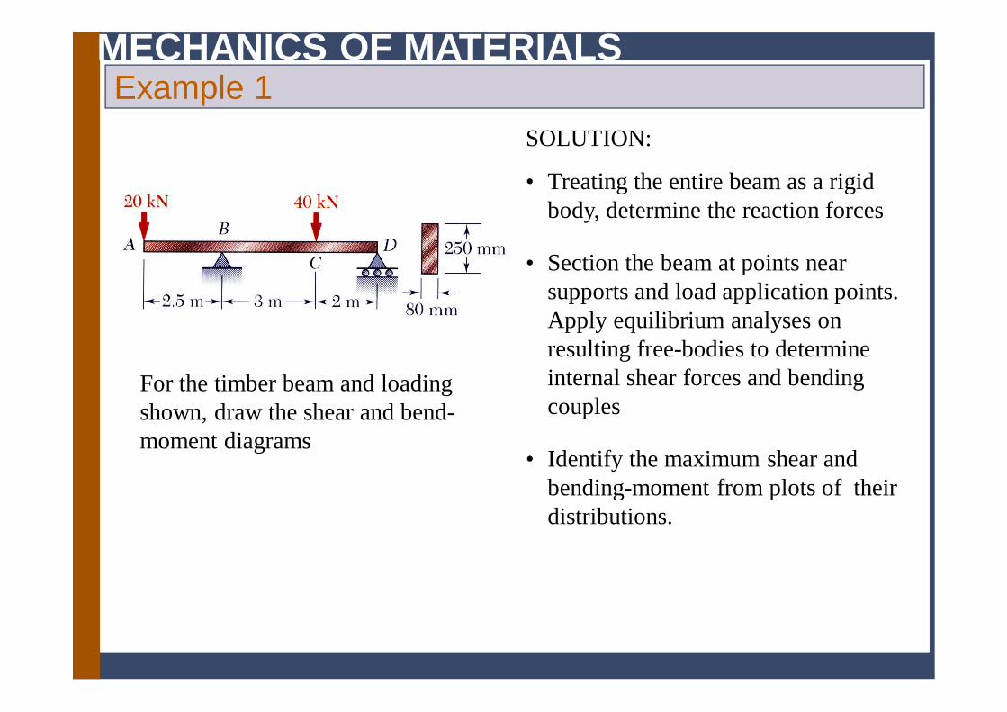
MECHANICS OF MATERIALSExample 1
For the timber beam and loading shown, draw the shear and bend-moment diagrams
SOLUTION:
• Treating the entire beam as a rigid body, determine the reaction forces
• Identify the maximum shear and bending-moment from plots of their distributions.
• Section the beam at points near supports and load application points. Apply equilibrium analyses on resulting free-bodies to determine internal shear forces and bending couples

MECHANICS OF MATERIALSExample 1
SOLUTION:
• Treating the entire beam as a rigid body, determine the reaction forces
kN14kN40:0 from DBBy RRMF
• Section the beam and apply equilibrium analyses on resulting free-bodies
00m0kN200
kN200kN200
111
11
MMM
VVFy
mkN500m5.2kN200
kN200kN200
222
22
MMM
VVFy
0kN14
mkN28kN14
mkN28kN26
mkN50kN26
66
55
44
33
MV
MV
MV
MV

MECHANICS OF MATERIALSExample 1
• Identify the maximum shear and bending-moment from plots of their distributions.
mkN50kN26 Bmm MMV

MECHANICS OF MATERIALSExample 2
5- 8
The structure shown is constructed of a W 250x167 rolled-steel beam. Draw the shear and bending-moment diagrams for the beam and the given loading.
SOLUTION:
Replace the 45 kN load with an equivalent force-couple system at D. Find the reactions at B by considering the beam as a rigid body.
Section the beam at points near the support and load application points. Apply equilibrium analyses on resulting free-bodies to determine internal shear forces and bending couples.

MECHANICS OF MATERIALSExample 2
5- 9
SOLUTION:
Replace the 45 kN load with equivalent force-couple system at D. Find reactions at B.
Section the beam and apply equilibrium analyses on resulting free-bodies.
kNm5.220450kN450450
:
221
1 xMMxxMxVVxF
CtoAFrom
y
kNm1086.12902.11080kN10801080
:
2 xMMxMVVF
DtoCFrom
y
kNm1531.305kN153:
xMVBtoDFrom

MECHANICS OF MATERIALSExample 2

MECHANICS OF MATERIALSRelations Among Load, Shear, and Bending Moment
xwV
xwVVVFy
0:0
D
C
x
xCD dxwVV
wdxdV
• Relationship between load and shear:
221
02
:0
xwxVM
xxwxVMMMMC
D
C
x
D Cx
dM Vdx
M M V dx
• Relationship between shear and bending moment:

MECHANICS OF MATERIALSExample 3
Draw the shear and bending moment diagrams for the beam and loading shown.
SOLUTION:
• Taking the entire beam as a free body, determine the reactions at A and D.
• Apply the relationship between shear and load to develop the shear diagram.
• Apply the relationship between bending moment and shear to develop the bending moment diagram.

MECHANICS OF MATERIALSExample 3
5- 13
SOLUTION:
Taking the entire beam as a free body, determine the reactions at A and D.
kN2.81
kN8.52kN6.115kN54kN900
0FkN6.115
m4.8kN8.52m2.4kN54m8.1kN90m2.70
0
y
y
y
A
AA
DD
M
Apply the relationship between shear and load to develop the shear diagram.
dxwdVwdxdV
- zero slope between concentrated loads
- linear variation over uniform load segment

MECHANICS OF MATERIALSExample 3
- bending moment at A and E is zero
- total of all bending moment changes across the beam should be zero
- net change in bending moment is equal to areas under shear distribution segments
- bending moment variation between D and E is quadratic
- bending moment variation between A, B, C and D is linear
dxVdMVdx
dM
Apply the relationship between bending moment and shear to develop the bending moment diagram.

MECHANICS OF MATERIALSExample 4
Draw the shear and bending moment diagrams for the beam and loading shown.
SOLUTION:
• Taking the entire beam as a free body, determine the reactions at C.
• Apply the relationship between shear and load to develop the shear diagram.
• Apply the relationship between bending moment and shear to develop the bending moment diagram.

MECHANICS OF MATERIALSExample 4
SOLUTION:
• Taking the entire beam as a free body, determine the reactions at C.
330
0
021
021
021
021
aLawMMaLawM
awRRawF
CCC
CCy
Results from integration of the load and shear distributions should be equivalent.
• Apply the relationship between shear and load to develop the shear diagram.
curveloadunderareaawV
axxwdx
axwVV
B
aa
AB
021
0
20
00 2
1
- No change in shear between B and C.- Compatible with free body analysis

MECHANICS OF MATERIALSExample 4
• Apply the relationship between bending moment and shear to develop the bending moment diagram.
203
10
320
0
20 622
awM
axxwdx
axxwMM
B
aa
AB
323 0
061
021
021
aLwaaLawM
aLawdxawMM
C
L
aCB
Results at C are compatible with free-body analysis