MECHANICS OF BENDING OF FIBER ASSEMBLIES by PETER ...
215
MECHANICS OF BENDING OF FIBER ASSEMBLIES by PETER POPPER B.S., Lowell Technological Institute (1957) S.M., Massachusetts Institute of Technology (1959) Mech.E., Massachusetts Institute of Technology (1964) Submitted in partial fulfillment of the requirements for the degree of Doctor of Science at the Massachusetts Institute of Technology February, 1966 Signature Certified l ~ Accepted by 0 ••• 0 •••• 0 0 •••• , ••••••••••••••• Chairman, Departmental Committee on Graduate Students Department of Mechanical Engineering -1""'
Transcript of MECHANICS OF BENDING OF FIBER ASSEMBLIES by PETER ...

MECHANICS OF BENDING OF FIBER ASSEMBLIES
byPETER POPPER
B.S., Lowell Technological Institute(1957)
S.M., Massachusetts Institute of Technology(1959)
Mech.E., Massachusetts Institute of Technology(1964)
Submitted in partial fulfillmentof the requirements for the degree of
Doctor of Science
at theMassachusetts Institute of Technology
February, 1966
Signature
Certified
l ~Accepted by 0 ••• 0 •••• 0 0 •••• , •••••••••••••••
Chairman, Departmental Committee on Graduate StudentsDepartment of Mechanical Engineering
-1""'

038MECHANICS OF BENDING OF FIBER ASSEMBLIES
byPeter Popper
Submitted to the Department of Mechanical Engineering onMarch 11, 1966 in partial fulfillment of the requirement forthe Degree of Doctor of Science in Mechanical Engineering.
This investigation is directed towards a determination ofhow fiber-to-fiber friction and fiber mobility in a fibrousstructure affect bending and unbending behavior. The classicaltheories for predicting this behavior involve the assumption ofeither a negligible or infinite interfiber frictional interaction,and the results based on these limiting assumptions cover a widerange of possible behavior. Experimental and analytical investi-gations of the intermediate cases of frictional interaction haveshown that the way in which fibers move relative to each otherduring bending can have a strong effect on the manner in whichthe properties of the individual fibers develop the propertiesof the fibrous structure. Moreover, it was shown that the actualbending "behavior and bending recovery obtained for the cases ofintermediate frictional interaction differ both quantitativelyand qualitatively from that of the limiting cases.
In order to evaluate the bending behavior of textile materials,a special instrument was designed and constructed to measurebending moment as a function of imposed curvature. Data obtainedon this equipment were used to establish the bending parametersof the various materials under investigation.
As a complement to the £u~damental considerations oftextile structures, a study was undertaken on the mechanics ofmulti-layer beams with interLayer friction. This was doneanalytically and the results were verified experimentally.
Thesis Supervisor: Professor Stanley BackerTitle: Professor, Mechanical Engineering
Head, Fibers and Polymers Division
-2-

ACKNOWLEDGEMENTSI would like to acknowledge the valuable assistance and
advice that I have received during the course of this investi-gation. Most of all, I am deeply grateful for the manystimulating suggestions, technical advice, and constantencouragement given to me by Professor Stanley Backer, theChairman of my Thesis Committee.
I would also like to thank three organizations for theirfinancial support during my studies and research: the ChemstrandResearch Center for their research grant covering the initialstages of this investigation; the Camille Dreyfus Foundationfor their fellowship during my graduate studies; and the u. S.Department of Agriculture for their research grant under whichthe major portion of this work was done.
Thanks also go to the staff and students of the Fibersand Polymers Division and to the members of my Thesis Committeefor the advice and assistance given. In particular, I acknowledgethe advice of Dr. Aly El-Shiekh and Mr. Pierfranco Marzoli givenin connection with the design of the test equipment; the assistanceof Mr. Abdel Sid-Ahmed in the experimental work and the prepara-tion of fabric cross sections; and the untiring labors ofMiss Dorothy Eastman in the typing of this thesis.
I also thank my wife, Rosalie, for her encouragement andfor the personal sacrifices which she has made during the periodof my doctoral studies. Finally, I thank my three beautifuldaughters, Lisa, Linda, and Laura (who was born during the earlystages of the thesis) for just being around, and brightening thesometimes gloomy days. The thesis is dedicated to them--Rosalie,Lisa, Linda, and Laura.
-3-

INTRODUCTION
TABLE OF CONTENTS
7
CHAPTER I. THE BENDING OF MULTI-LAYER BEAMS WITH FRICTIONBETWEEN THE LAYERS 13
General AnalysisLoad-Geometry Relation 15Strain Distribution 21Slip Distribution 22Longitudinal Shear 23
Longitudinal Shear Stress due to Shear Force 24Longitudinal Shear Stress due to Discontinuous
Distribution 27Application of the Theory
Simply Supported Beam with Constant Normal Force--Theoretical 29
Simply Supported Beam with Constant Normal Force--Experimental 35
Propagation of Slip in Simply Supported Beam 40Beam Loaded with Constant Bending Moment 48Propagation of Slip in Beam with Constant Bending
Moment 52Recovery from Constant Curvature Bend 55
Discussion of Chapter I 60
CHAPTER II. THE EFFECT OF FRICTION ON THE BENDING OFTEXTILE STRUCTURES 63
Limiting Analyses for the Prediction of Bending Behavior ofCertain Textile Structures 63
-4-

Zero Twist Yarn 65Twisted Yarn 68Bonded Fabric 69
Qualitative Effects of Friction on Bending Behavior 70
Fiber Motions During Bending 75Continuity Equation for Fiber in a Deforming Structure 75Effect of Friction on One-Dimensional Slip and Strain 85
Frictional Effects in .Yarns 92Zero Twist Yarn 92Twisted Yarn 95
Friction Moment for Constant Pressure 101Friction Moment for Constant Tension 103
Frictional Effects in Woven Fabrics 104Friction Moment due to Relative Fiber Motion 105Parallel Yarn Rubbing 114Structural Effect on Elastic Rigidity 118Relation Between Friction and Extent of Slip
Propagation 127
CHAPTER 1110 BENDING RECOVERY OF TEXTILE STRUCTURES 140Representation of Bending Recovery 141Bending Recovery of a Single Fiber 142Limiting Cases of Frictional Interaction 143Effect of Friction on Recovery 147
Friction Elastic Effect 147Frictionally Induced Strains 148
Combined Effects of Friction and Permanent Fiber 151Deformation
Evaluation of Cross-Sections of Bent Fabrics 164
-5-

CHAPTER IV 0 EXPERIMENTAL TECHNIQUESInstrument for Measuring Moment-Curvature Relation
Drive MechanismMethod of Sample GrippingMeasurement of Bending MomentCalibration
Measurement of Bending RecoveryLow Curvature RecoveryHigh Curvature Recovery
Measurement of Frictional ForceFrictional Force in Multi-Layer BeamsFrictional Force in Woven Fabrics
Measurement of Bending Behavior of Multi-Layer BeamsTechnique for Embedding Bent Fabric Samples
CONCLUSIONSSUGGESTIONS FOR CONTINUING RESEARCH
APPENDIX AAPPENDIX BAPPENDIX CAPPENDIX DAPPENDIX E
APPENDIX F
BIBLIOGRAPHY
-6-
170173179180180181181182185185186187187
190194
201203204205207210
212

INTRODUCTION
One of the fundamental differences between textilematerials and other types of sheet structures is that textilesgenerally exhibit unusually high flexibility. Because of this,they can be used satisfactorily in a wide variety of applica-tions requiring extremely low bending rigidity, the mostsignificant, of course, being clothing. Textile fabrics aremade of large numbers of fine fibers that may have considerablefreedom of motion relative to each other. When this mobilityexists, the fiber strains which develop during bending orcreasing of the fabric are considerably lower than thosewhich develop in bending of corresponding solid sheetmaterials 0 With this mobility the potential flexibility ofthe fibers can be realized and the fabric structure will, inturn, have a low bending rigidity. If, on the other hand,fiber mobility is restricted, the strains which develop duringbending will be of considerable magnitude and the fabricwill be correspondingly more rigid.
Another important attribute of textile materials istheir ability to recover from imposed bending deformations.This recoverability, like flexibility, also depends on thefineness of the fibers and their ability to move relative toeach other. When the fiber diameters are much less than thefabric thickness, and when interfiber mobility exists, thestrains which develop during bending or creasing will bemoderate 0 The permanent fiber deformation will be small andthe recovery of the structure will be good. If the fibersdo not have mobility in the structuret the strains whichdevelop during bending will be considerably greater and causemore permanent fiber deformation and poorer recovery of thestructure.
-7-

Since both the bending and bending recovery behavior oftextiles are of prime importance in their end use, it isimportant to understand the factors which determine thisbehavior. The most important factor is, of course, the indiv-ual fiber properties. Fabrics made of flexible fibers aregenerally flexible and fabrics made of fibers with a highdegree of tensile recovery generally have a high bendingrecovery. However, this holds true only if the fibers havemobility in the structure. If relative fiber motion isrestricted, then a structural interaction develops which canhave a strong affect on the translation of fiber to fabricproperties. This interaction generally increases the fabricrigidity and decreases bending recoverability. In the limit-ing case of an interfiber interaction that prevents allrelative fiber motion, the fabric will behave almost as asolid sheet structure. For this reason, it is of fundamentalsignificance to develop an understanding of the factors whichgovern the motion of fibers in textile structures. Thesemotions depend on the geometric arrangement of fibers, thefiber properties, and the interfiber frictional interactions.Determination of this dependence and of the effect of fibermobility on fabric behavior is the fundamental objective ofthis investigation.
In the most general sense, what is required for a fullunderstanding of the mechanics of bending of textile structuresis a relation between bending behavior, fiber properties, andstructural geometry. This involves an understanding of howthe properties of the individual fibers develop theproperties of the structure for any given geometric configura-tion. The complete answer to this question is not availableat present, nor will it be for some time. Nevertheless, itis hoped that the information reported-here will contribute
-8-

significantly to our understanding of this phenomena and thatit will stimulate continuing research in this area.
There are a number of important reasons for understandingthe bending mechanics of textiles that should be of importanceto both fiber and textile manufacturers. For the fibermanufacturer it is important to know the relative importanceof the various fiber properties on bending behavior. Thisfacilitates the modification of existing fibers or thedevelopment of new ones to meet specific needs. The textilemanufacturer, on the other hand, would be interested inselecting the proper fiber for a particular use anddetermining how to best convert 'it into a fabric. He wouldalso like to be able to predict the effect of any particularfinishing treatment and then be able to characterize accuratelythe bending and recovery of the materials produced.
The problem of pre dicting bending behavior in textilesis classically dealt with in the literature by means of oneof two limiting assumptions v. The fibers are either assumedto have complete freedom of motion, or no freedom of motion.In the first case, the frictional effects are neglected; andin the second, they are assumed to be of sufficient magnitudeto prevent any relative fiber motion. The differences in thepredictions for the two cases are considerable as would beexpected 0 A loosely made fabric with complete freedom ofmotion is much more, flexible than one that has been treatedwith starch, for example, and has no freedom of fiber motion.
Since the difference between the predictions for theselimiting conditions is very large, it is important to have ameans of understanding the mechanics of the intermediatecases of frictional interaction. That is the specific problemdealt with in this research. It will be shown that the
-9-

behavior for these cases need not be the same qualitativelyas that found in the limiting cases. In particular, theenergy losses that occur when fibers slide against a frictionalrestraint produce a non-linear behavior that is qualitativelydifferent. This affects both bending and recovery as willbe discussed in detail in the text.
A number of previous investigations have dealt withthe intermediate effects of friction. Platt et al 8 assumedthat one way friction can act is to cause the fibers to formclusters in the structure. On this basis they developedcertain predictions of bending behavior. Abbott et a19
proposed that the intermediate effect was to cause lengthwisesegments of yarn in a fabric to bend alternatingly withcomplete and no freedom of motion. Later, Zorowski and Chen 10found that a ply yarn could be considered to bend with a coreof non-moving fibers surrounded by fibers acting under completefreedom of motion. In the mathematical treatments to bepresented it will be shown that some of these proposedmechanisms can be explained in terms of the mechanics of slippropagation during bending.
Non-linear effects of bending were also found by some.11 12. 7investigators. Issh~ ,Eeg-010fsson ,and L~vesey and Owens
10found them in constant moment tests; and Zorowski ,andGroSberg13 found them in cantilever and buckling tests. Thesewill also be considered in the treatments to be presented.
Frictional effects on bending recovery were considered14in a number of investigations. Bostwick et al demonstratedthat low amplitude mechanical vibrations during recoverycould improve the ability of fabrics to straighten; andDanielsl5showed that friction can have a strong effect onrecovery, especially for low curvature bends. In addition,
-10-
16others have shown that fiber surface treatments often havestrong effects on bending recovery.
During the course of this work it was found that somemeans for carefully measuring the bending behavior of fabricswas needed. Since there was no commercialinstrument available and since previous desi&ns of instrumentsof£his kind were not considered optimal, a special testinstrument was designed and constructed. On this piece ofequipment it is possible to measure continuously the moment-curvature relation of textile materials. From this measure-ment, two parameters we~e found to be capable of describingbending behavior for low curvature bends.
The thesis is divided into four chapters. In the first,the mechanical behavior of multi-layer beams with frictionbetween the layers will be examined 0 This type of structurehas many aspects of mechanical behavior ana~agous to that oftextiles, and the results obtained are applied to .textilestructures whenever possible. In the second and third chapters,the bending and bending recovery respectively are discussedfor various types of textile structures. These investigationswere performed by both experimental and analytical means.Then, in the last chapter the test instrument developed willbe described in detail, together with all of the experimentalprocedures used.
There are a number of applications to which the resultsof this research may be applied. The proposed theory ofmulti-layer beams may be used to solve a number of problemsfor layered structures in which frictional effects aresignificant. In addition, the unusual effect of "reversecurvature" which was noted from the mathematics and demonstratedexperimentally may have some practical implications. Thiseffect involves unusual deflections in this type of structure
-11-

under certain types of loading.The primary significance of the work done on the bending
of textile structures is to add to the information alreadyavailable and to clarify some of the mechanisms by whichfriction acts~ The specific applications of this informa-tion relate to such factors as fabric stiffness, hand, aesthetics,comfort, drape, buckling behavior, non-linear behavior,energy absorption; and others. In addition, the approache~taken can in some cases be applied to pressurized fabricstructures where rigidity and recovery are often of primeconcern. For example, in the design of a full pressure suit27the requirements are for low rigidity, and contrary to thecase of textiles in general, poor recovery from bending.
The results of the investigation on bending recovery canbe used to aid in the improvement of this extremely importantproperty for clothing fabrics. From the results obtained, itis possible to estimate the effects which can be expected bya given frictional treatment, fiber modification, or structuralrearrangement.
The experimental techniques used in this investigationmay have applications in continuing research on this generalproblem. In particular, the instrument designed for measuringthe moment-curvature relation may be useful for other researchinvestigations or for routine measurements.
While the analyses and experimental results presented inthis thesis certainly do not answer more than a fraction' ofthe overall problems in this field, it is hoped that theyrepresent a useful contribution to the existing technologyand that they can be used to help others in continuing thiswork.
-12-

CHAPTER I THE BENDING OF MULTI-LAYER BEAMS WITHFRICTION BETWEEN THE LAYERS
In order to establish the fundamentals of mechanical behaviorof a complex structure, it is often useful to consider the mechanicsof a highly id~alized model. If the essential features of both arethe same, then an analysis of'the model 'willi,provide an understand-ing of the behavior of the structure.
If the complex structure of interest is a textile materialsubjected to bending, then a useful idealization can be found ina multi-layer beam having friction between the layers. In boththe textile and the multi-layer beam the individual elements--thefibers or the layers--slide by one another as the system bends.This sliding may be resisted by frictional interactions in bothcases and this results in an alteration of the mechanical behavioras compared to the case where no friction exists between thelayers. First, the friction system is ~tiffer than the zerofriction system; second, there may be energy lost in bending; andthird, imposed deformations are not generally completely recoverable.These three effects can occur in a friction system even if theindividual elements are completely elastico They are observed inboth textile materials and layered beams which display frictionalinteractions 0
This chapter will deal exclusively with multi-layer beamsand the results applicable to textile structures will be utilizedin the following chapters of this thesis. The general problemunder consideration here is the determination of how interlayer~riction ~ffects the mechanics of multi-layer beams. Morespecifically, such things as load-geometry relation, straindistribution, slip distribution, recovery from loading, and propa-gation of slip are to be analyzedo
As a first approach to the problem the limiting cases offrictional interaction can be considered--namely, zero and
-13-

"
infinite friction. When there is no friction between the layers,the beam will deform as a classical beam having a rigidity equalto the sum of the individual layer rigidities. There will be noenergy loss due to frictional interaction and the beam willrecover completely from an imposed load. When the frictionalinteraction is infinite (or large enough to prevent any relativemotion between the layers) the beam will clearly act as though itwere a solid rather than a multi-layer beam. In this case therigidity will be considerably higher than that of the previouslydescribed beam and again there will be no energy loss due tobending and the beam will recover completely if the material iselastico The mechanics of both limiting cases of frictional effecthave been considered in classic textbooks on strength of materialsand a number of special investigationsl,2,3.
When friction acts between the layers of a beam, there willbe an energy loss at each layer interface when the layers moverelative to each other. This will have a significant effect onthe mechanical behavior of the beam. The relation betweenload and deflection will be non-linear, it will depend on thedirection of loading, and the recovery will not be complete. Thecase of a two-layer beam with friction and constant normal pressurehas been investigated by Goodman4 for an end loaded cantilever.He found this type of behavior to hold true in his investigation.In bending measurements of textile materials, Livesey and Owens 7:found similar results for fabric samples.
From fundamental engineering considerations, a generalanalysis of a multi-layered beam will be developed. From this, anumber of special cases will be solved and experimental resultspresented 0 The information useful for the analysis of textilestructures will be extracted and used in the following chaptersof the thesiso
-14-

GENERAL ANALYSIS OF MULTI-LAYERED BEAMS WITH FRICTION
-1= curvature of centerline of beam (in )• tension on beam (lb)
fs
vM
T
k
Load-Geometry Relation. The general problem to be solved is thedeflected shape of a multi-layered beam subjected to arbitrarytransverse loading. More specifically, consider the beam shownin figure l-:l.There are N layers indexed with the subscript "iltstarting at a value of one for the bottom layer. Furthermore, let:
E = tensile modulus (lb/in2)w = layer width (in)h = layer height (in)
(~e = layer moment of inertia (in4)N = number of layersVi = shear force on i-th layer (lb)Mi = bending moment on i-th layer (in/lb)Ti = tension on i-th layer (lb)f. = shear stress per unit width on bottom of i-th
1-
layer (lb/in)fk = shear stress per unit width corresponding to
sliding friction force (lb/in)= shear stress per unit width corresponding to
static friction force (lb/in)= shear force on beam (lb)= bending moment on beam (in/lb)
ei = tensile strain in x-direction in i-th layery = coordinate measured from center of beam to
arbitrary point (in)y. = coordinate measured from center of beam tol.
center of i-th layer (in)x,z = space coordinates of centerline of beam (in)Ci = average tensile strain on i-th layerb. = strain discontinuity term for i-th layer
1.
-15-

z
M
Fig. 1-1 MULTI-LAYER BEAM
rd V ·V · + J d x, "0 x
~~~c~Fig. 1-2 ELEMENT OF MULTI-LAYER BEAM
-16-

~ )). = integration constantsJ l
u.+l · = relative motion between layers i, i+l (in)1 ,1
s = length coordinate along beam (in)k ... 1 (. -1)= 1n1t1a curvature 1no~ = tangent angle~o = initial tangent angle
It will be assumed that:1. The radius of curvature of the beam is small
compared to the beam thicknesso2. The material is linearly elastic.3. The loading consists only of transverse loads.4. The displacements are small.
The procedure used in formulating this analysis will firstbe to establish the types of strain distributions which arepossible for a multi-layer beam and then to insure that eachelement of the beam is in equilibrium with the imposed loadso
The strain distribution in each layer consists of two parts,one related to the curvature of the layer in question and theother to the average tensile strain c .. Expressed mathematically,
1
this is,(1-1)
Under assumption 1, i.e. y.k is small, this becomes,1
, 'e. = yk + b.1 J.
(1-2)
where b. is Ci - y.k. Note that the result of the strain analysis1 1
indicates that the strain on any layer consists of two terms, onlyone of which (b.) depends on the layer index 0
1Since the value of b. may be different for each layer the
1
resulting strain distribution may be discontinuous. Althoughthis is not possible for a conventional beam, it is certainly thecase for multi-layered beams. The difference between the valuesof b. for two adjacent layers is, of course, a measure of this
J.
strain discontinuity; and, as will be demonstrated later, ameasure of the relative layer motiono
-17-

In the extreme case of no relative motion between the layers,all the bits are zero and the strain distribution is the same asthe classical case. (ei a yk)o When there is no frictionalinteraction and the layers act independently, th~ equation reducesto ei = k (y - Yi). The intermediate cases of friction, which areof interest here, follow the form of equation 2 and the particularvalues of b. will depend on the loading and the frictional inter-
1
actionoIt should be noted that the values of k and bi vary with
position along the beam and k is a function of x only, and bvaries with both x and io
The equilibrium conditions will be established by assuringthat each element of each layer and the beam as a whole is inequilibrium with the imposed forces and moments. Taking firstthe force equilibrium in the x-direction of an element h dx ofone layer and referring to figure 1-2 gives,
(1-3)
(1-4)
(1-5)
(1-7)
(1-6)
The force balance on the beam as a whole under the assumption ofsmall deflections and transverse loads results in the requirementthat the total beam tension be zeroo In terms of the variablesof interest, this becomes,
N!T '" i. T .... 0
,._ 1N 1=-'1
L::; (ky. + b.) :I 0~ 1 1
i=sl--18-

The moment equilibrium requirement of an element of one layer canbe found by again referring to figure 1-20 Summing moments aboutthe centerline of an arbitrary layer gives,
(1-8)
(1-9)Note that the sign convention established for the f. terms is
~shown on figure 1-20 Summing the individual shear forces givesthe overall shear force 0
(1=10)
(I-II)
This equation may be written in terms of the moment on the beamoFo~ this purpose, the classical relation between shear forceand bending moment may be used. This relation is independent ofthe frictional effects within the beam 0
dM = Vdx
Alternatively, an equation for bending moment on the beam maybe obtained by integrating ~he individual components of stressacross the beamo The result of this operation gives the sameeffective result as equation 10, but in different form 0
b. y.~ ~
(1-12)
One other relation required is the equation for determiningthe location of the center of the i-th layero This can be shownto be,
(1=13)Algebraic manipulation of the above equations gives the
relation between loading and geometry for a fixed frictionalinteraction. In this relation, load is expressed by the shearforce and the geometry is given in.terms of the curvature 0
...19=

dk N.V a NE~ dx + h?2 fi1.::1
(1-14)
The shear stress terms,:fi, in equation 14 must be ev~luatedin o~der to solve the equationo This can be done immediately fortwo special cases~ one in which there is no strain discontinuity; ,and one in ~hich the shear stress is constant from layer to layer.
When there is no motion between the layers of the beam, thestrain discontinuity (hence b.) is zero and the load geometry
1.
relation can be obtained from equations 11 and 120
v = N3 EI. dk1. dx (no slip) (1-15)
When all the layers move relative to each other (the conditionof complete slip), and when the normal force (between layers) andthe coefficient of friction at any location along the beam areconstant, the frictional forces, f., will also be constant at any
1.
location 0 This type of behavior corresponds to a complete sl:i:ppagebetween the layers against frictional restraint 0 For a region ofthe beam where the direction of slip is such that the frictionforces are positive according to the established sign convention,the result is,
v ~ NEI. ok + h (N-l) f1. dx 'k (complete slip) ','.'(1-16)
This equation gives the load~geometry relation for loadssufficiently high to produce complete slipo The applicable rangeof equation 15 and of equation 16 will depend on the nature ofthe propagation of slip through the bearno This will be consideredin greater detail latero
An interesting consequence of equation 16 can be found byexamining the effect of the friction termo If the equation isintegrated, it shows that the curvature of the multilayer beammay be different from zero eyen in a region having zero moment.Furthermore, this equation shows that in the region of non-zeromoment it is possible to have a point of zero curvatureo Bothof these effects are not found in conventional beams. They willbe explored in greater detail in the applications section of
<=>20-

this chapter.For the case of no frictional interaction, the behavior of
the multilayer beam is governed by equation 16 without the secondterm. This is the same as an equivalent ~eam having a rigidityequal to the sum of the individual rigidities of the layers. Thedifference in rigidity between this case and the case of infinitefrictional effect is obtained by comparing this result with thatof equation 15. The solid beam will be stiffer than the zero
2friction multilayer beam by a factor of N 0
Strain Distribution. The strain distribution in the beam can bewritten from the equations already derived. The general formis,
e. == yk + b.1. 1.
For the case of no relative motion this becomes,e. :B yk1. (no slip) (1-17)
e. ==1.
For the case of complete slippage against a constant frictionalrestraint the strain may be computed by establishing the valuesof k and bi from equations 5 and 16 in integrated formo Theresults are,
(V-h(N-l)fk,
NEI. 1x (Y-Yi) +Cy +4, i + 1, N. 1.
'.~.V-h(N-l)fk~', Pr'" fkxl- (Y-Yi) +~ +~- --- igl (1-18)\NEIi y 1. Ewh, (1 1.)'" comp ete s 1.p
~-h(N-1)fk I . I"r fkx ..\:: NEl
ilX (Y-Yi) +Cy +oUi + Ewh, J. .... N
The quantities C and JJ are integration. constants determinedfrom the nature of the loading. The sUbscript'on~indicatesthat the value of this constant depends on the layer in questionoNote that during the case of complete slip, the interior laye~shave identical strain distributions differing only in theintegration constant; and this constant is zero for many situationso
-21-
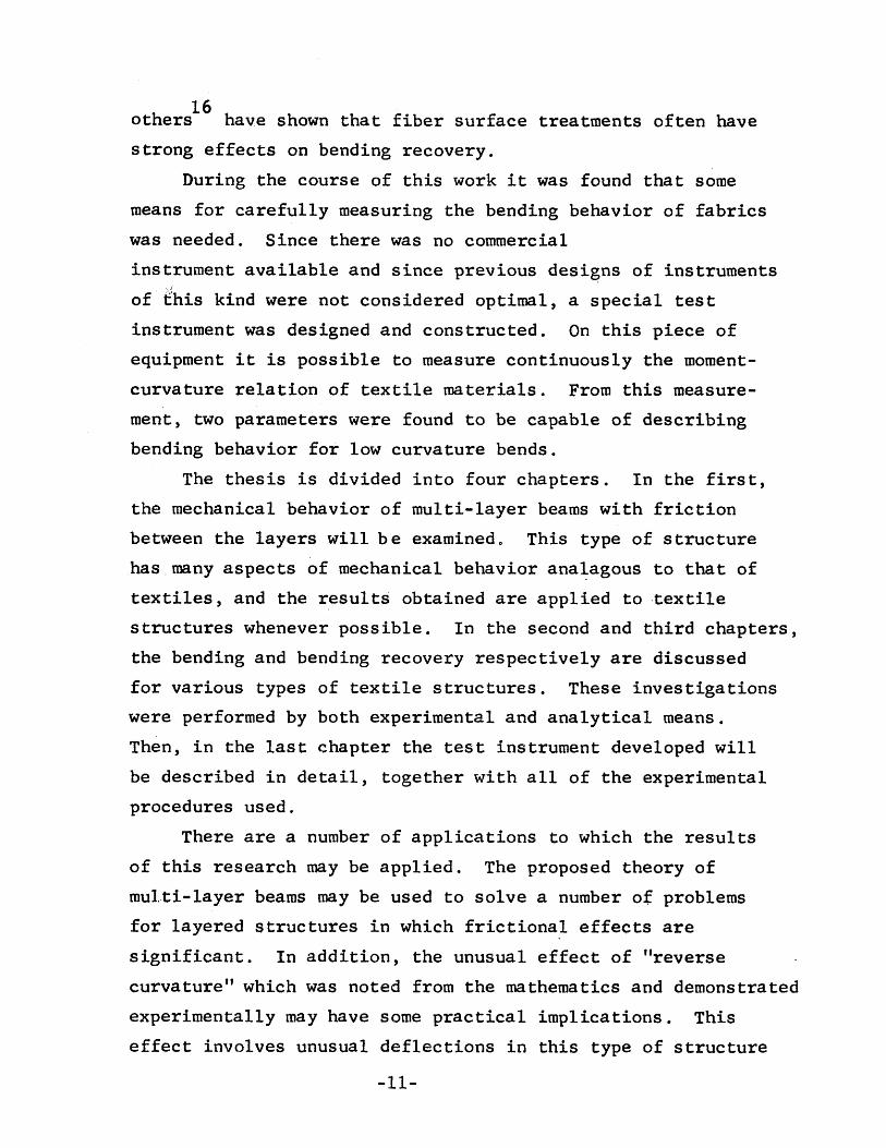
Slip Distribution 0 The relative motion between two layers can befound by taking the difference between the absolute motion ofpoints at the interface of two adjacent layers. The displacementof a point at the top of layer i can be shown to be,
du .top, 1.dx = etop,i (1-19)
Similar1y~ the displacement of a point at the bottom of layeri + 1 is,
dUboto,i+1 = e (1-20)dx bot.,i+lCombining these two equations and substituting for the straindiscontinuity between the two layers gives the relative motion.The direction of positive relative motion has been chosen tocorrespond to a positive frictional force and the result is,
dU.+1 .__ 1. ,1. ~ b _ b (1-21)dx i+1 i
The slip distribution may be formulated in an alternate wayto provide a result that is useful for certain calculations.Consider a multilayer beam having an initial curved shape that isdeformed to a new geometryo Assume that the layers remain incontact and that the relative slip may be approximated by that ofa beam ~Aving no frictiooo Let s be a coordinate running alongthe interface between the i + 1 and i-th 1ayerso The relativemotion of the layeX"B can be found in teX'ms of the strain distribu~tions as before 0
dU ...a.,l •1. ij ,l. ( 22ds ~ eboto,i+l - etoP9i 1- )
In this case, however, the strains may be evaluated in termsof the changes of curvature to give the relative slipo
heboto,i+l = - 2 (k = ko) (1-23)h~top,i ~ 2 (k = ko) (1-24)
dU'-obl •__ 1.. ,~~ ~h (k - k )d~ 0
=22=
(1-25)

This analysis is not restricted to small deflections and themost useful result is obtained by replacing the curvature with thederivative of tangent angle with respect to arc length.
du 0+1 01. ,~
ds
k :=! ~
ds
= -h rM _ d ce 0)
\dS ds:';
(1-26)
(1-27)Integrating gives,
uO+l 0 (s) = -h [~(s) - cp (S)] + uO+1 0(0)~ ,1. 0 - ~,1.
(1-28)This equation shows the interesting result that the displace-
ment at any point depends only on the change of tangent angle ata given location and an additive constanto It means that therelative motion an element feels is not dependent on the changein shape of the beam, but only dependent on that particularelement's change of tangent angle. For the case of an initiallystraight beam with the coordinate s measured from a point havingno relative slip, the relative motion will be,
ui+l,i = -h~ (1-29)
Longitudinal Shear Stress. In the previous analysis, the generalequations were reduced to the special cases of no relative motionand complete relative motion against a frictional restraint. Thequestion still remaining is to find how slip propagates throughthe beam as the load is increased.
The approach taken is to compute to local shear stressestending to separate the layers of the beam befo~e slip occurs andcompare this value to the shear stress that can be resisted bystatic friction between the layers. Clearly, if the imposedshear stress is below that which can be resisted~ thexe will beno slip and if it is greater, there will be slipo
In order to make the comparison between the imposed andallowable shear stresses, it is necessary to know the nature ofthe loadingo However, the values of imposed shear stress can be
.,,23-

calculated in a fairly general sense. That will be done in thissection; and, the results obtained will be used to compute thepropagation of slip in two of the examples given in the applicationssection of this chapter.
The longitudinal shear stress of a solid beam has been solvedby classical beam theory methods 6. In this case, the shearstress results from an imposed transverse shear force on the beam.In multilayer beams a shear force will also produce a longitudinalshear stress, but surprisingly enough it is possible to have alongitudinal shear stress even if there is no transverse shearforce. This is because discontinuous stress distributions canoccur in multilayer beams, and they can cause longitudinal shearstresses. For this reason the computation will be broken into twoparts and the two contributing factors to longitudinal shearstress will be analyzed separately 0
Longitudinal Shear Stress due to Transverse Shear Force. Tohave a measure of the shear stress tending to separate the layers,the shear stress distribution must be computed for an arbitrarynumber of layers sticking together. In addition, it is necessaryto allow any combination of surface shear forces to act on top andbottom of these layers 0 There are three such combinations ofinterest~ in ~he first, all the layers stick together and there iszero surface shear stress; in the second, a group of interiorlayers sticks together and there is a constant shear stresscorresponding to sliding friction on both sides of the group;and in the third, a group of layers has one side on the interiorof the beam where the sliding frictional stress acts and one sideat the surface of the beam where there is no shear stress.
In order to solve for the three cases mentioned above forany number of layers sticking together in a group, consider anelement h*dx of the beam shown in figure 1-3, also a subelement
* *(h /2 - y )dxo NoW let:ft ~ shear stress per unit width on top of element
(lb/in)

fb = shear stress per unit width on bottom ofelement (lb/in)
f * = shear stress per unit width at position y* (lb/in)y
*'y = coordinate measured from center of the group (in)to the bottom of the sube1ement.
Ts = tensile force on subelement of figure 1-3 (lbs)h* = height of element (in)e = strain at any point
. *et
= average stra~n on element, h dxJ = dimensionless coordinate.
--
f. dx
<
f *y '*y
+ dT s
Fig. 1-3 Force Balance on a Volume Element in a Groupof Non-Sliding Layers
..,25..,

(1-31)
An equation for the shear stress at any position within thegroup of layers may be obtained from the condition of forceequilibrium in the x-direction. For the sube1ement shown infigure 1-3 this is,
dTsdx = fy* .. ft (1-30)*A similar force balance for the h dx element of figure 1-3 yields,
deT fb - ftdx = EWh*
The tension on the subelement may be found by integrating the
stress disjtribrion, * ] [ * ]Ts" Ewedy* = ~w [k~ + kl + 2eT ~ - y*
Substituting this result into equations 30 and 31 and using a. *dimensionless coordinate ~n place of y gives the result,
(1-32)
(1-33)
(1-34)
cases mentioned before can be solved byvalues for the shear stress on top and
2Y*h*
The three specialtaking the appropriatebottom of the group of
Case 1 fb a
~ayersof = 0t
The results are:(group?f layers corresponds tototal beam)
(1-35)
Case
*2Ewh dk (1 _J2)fy* l1li 8 dx
2 fb m ft • fk (group of layers 'is on interiorof beam)
2fy* • E:h* ~ (1 - J 2) + fk
-26-
(1-36)

Case 3 fb 0, ft = fk (bottom of group of layers lieson surface of beam and top ofgroup lies in interior)
*2 ff * :I Ewh dk (l _ S 2) +.J5 (1 + 5 ) (1- 37)y 8 dx 2
Nute that the distribution of shear stress is parabolic inall cases and has the appropriate values on the boundaries. It isexpressed in terms of rate of change on curvature instead of shearforce 0 This is because the relation between shear force and rateof change of curvature depends on the particular problem inquestion and the mode of slip propagation.
In the applications section of this chapter the imposedshear stress will be computed and compared to the allowable shearstress 0 This will permit calculation of the development of slipthroughout one type of loaded beam.
Longitudinal Shear Stress due to Discontinuous StrainDistribution. The shear stress developed by a discontinuousstrain distribution exists even if there is no net shear force onthe beamo To demonstrate this point, consider a multilayer beamsubjected to a symmetrical four-point loading. In the centralregion of the beam there will be a constant moment and no shearforce 0 However, if the friction between the layers is moderate,they will slide by one another even in the region where the shearforce vanishes. The explanation for this phenomenon lies in thefact that if slip occurs in the region just outside of theconstant moment zone, the stress distribution at the boundary of
,
the zone will be discontinuous. This discontinuity will producea shear stress along the interface of two layers as shown on figure1=40'
The shear stress will be greatest at the beginning of aregion of no slip and it will decrease to zero in a relatively shortdistance 0 If it exceeds the shear stress that can be resistedby static friction, slip will start propagating into the material.As the slip propagates, the strain discontinuity will diminish
-21-

due to a reduction of curvature, and thereby reduce the imposedshear stresso The propagation will then continue until the imposedshear stress is no longer great enough to overcome friction •
.----.---f.. -''0 .-- •. - ••• _--. __ •• __ -._-- •• --.-------.-.-----------
d,i- ~ +- ...-.-.----------------- ----1~~~ -':-
........--.-------..----.- ..---------------- -------4
Fig. 1-4 Longitudinal Shear Stress in Non-Slipping RegionDeveloped by Discontinuous Strain Distribution
In order to estimate the shear stress for the case of straindiscontinuity a two-dimensional stress analysis was used. Theshear stress distribution was assumed to be the same as that in alarge solid block of material subjected to a sawtooth stressdistribution on each side. This assumption makes it possible touse the available solutions for the stress distribut.ion in amaterial loaded by sinusoidally varying loads on both sides. Thissolution can be summed by a Fourier series to obtain the resultsfor the discontinuous loads actually applied. The details ofthe calculation are given in the Appendix A and the resultingshear stress function is,
-21(x
Ew [271 x~ e hfd i :::i rr -h- -d:!J1. (bi-l - bi), 1 - e h
-28-
(1-38)

Where:fd . = shear stress per unit width on bottom of i-th,~
layer due to discontinuous strain distribution. (lbs/in)x = distance along the beam measured from beginning
of no slip region. (in).The shear stress decays rapidly and at a distance equal to
about one layer height its magnitud~ is about 1% of the originalvalue. The maximum shear stress occurs at the ~eginning of theno-slip region and its value is,
Ewfd . = ~ (b. 1 - b.) (1-39)
,~ 1/ ~- ~
max
This imposed stress will determine whether or not slip willpropagate into a multilayer beam when it is compared to the staticfriction force per length that can be generated between the layers.
APPLICATIONS OF THE THEORY OF BENDING OF MULTIlAYERED BEAMS
WITH FRICTION
Simply Supported Beam with Constant Normal Force--Theoretical. Asa first example of the proposed theory, consider a beam that issimply supported as shown on figure 1-5. From symmetry the beamcan be replaced by a cantilever of one-half the length as shown.
The problem is to estab~ish the deflected shape of the beamfor a given loading. To do this, the following assumptions willbe made:
I. The assumptions of the general analysis hold20 The normal force between layers is constant and
unaffected by the imposed bendipg loads3. The slip has propagated th~oughout the beam.
(This last assumption will be dropped later when thetransition region is examined in detail.)
Let:a = position of load applicationL ~ lengt~ of cantileverX,z = coordinate system for describing centerline deflection.
-29-

with other variables as before.The equation for relati.ng load to geometry can be obtained
from equation 16 by substituting the appropriate values of shearforce in each of the two regions of the beam. The result is,
-h(N-l)fkdk =dx NEleV-h(N-l)fk
NElea<x<L
(1-40)
v
L1J_l_LJ __LLJ_LJ,--LLJ~-LL
.................... " .......•. _ .._-_ .._..._--_._-----
....__._-.--.--.-..---------~-----_t
ShearForce
!~ x.V
z !-'
/'
.-./
a~L
V
Fig. 1-5
-_.~
o . -..._ .. '--a: _.....--- L x_;>
Simply Supported Multi-Layer Beam under ConstantTransverse Pressure
-30-

Equation 40 can be integrated and the constants evaluated bysetting the curvature equal to zero at the free end and by assuringits continuity between the two regions. Then, the resultingcurva-ture function can be set equal to the second derivative ofthe displacement since the deflections are assumed small.
o<x<a(1-41)
a<x<L(V-h[N-l]fk)x Va- --NEIy.. NEIe .
An interesting observation can be made from this equation.In the region of the beam outside the point of load applicationthere is neither a shear force nor a bending moment. However,there is a curvature in this region, and its direction is oppositeto that in the region near the wall. This effect will be referredto as "reverse curvature". It has been observed experimentally(see figure 1-8) and constitutes perhaps one of the most interestingeffects of friction in a multilayered beam. When the frictionalforces are sufficiently great so that the beam behaves as a solid,there is no reverse curvature; and, when the interlayer frictionis zero, there is also no reverse curvature. Clearly then, thiseffect is limited to those intermediate cases of friction wherethere is relative motion against a frictional restraint.
Another interesting effect which is predicted by equation 41and was observed experimentally is that the curvature is zero be-tween the load and the wall.. This occurs at a point at which thebending moment exists. In classical beams that are originallystraight, inflection points occur only at points of zero moment.
The differential equation for the beam deflection can mosteasily be solved by first converting it to dimensionless form.For this purpose let,
v = z/L = dimensionless deflectionu = x/L = dimensionless coordinate along beam~= aIL = dimensionless load location
-31-

(N-l)fkhL2
R=-----NElj
L2VS ==--NE1.R
= dimensionless measure of relativeeffect of friction to elasticity
= dimensionless deflection of endloaded cantilever with no friction.
Substituting these variables into equation 41 gives the dimension-less differential equation and the boundary conditions.
d2ar"tRU
o<u<odu2 = (S-R)u - So a<.u~l (1-42)
dtt-{l) =rY'(l) == 0duThis equation can be solved with the additional requirement thatthe displacement and slope be continuous at the point of loadapplication. The resulting solution is,
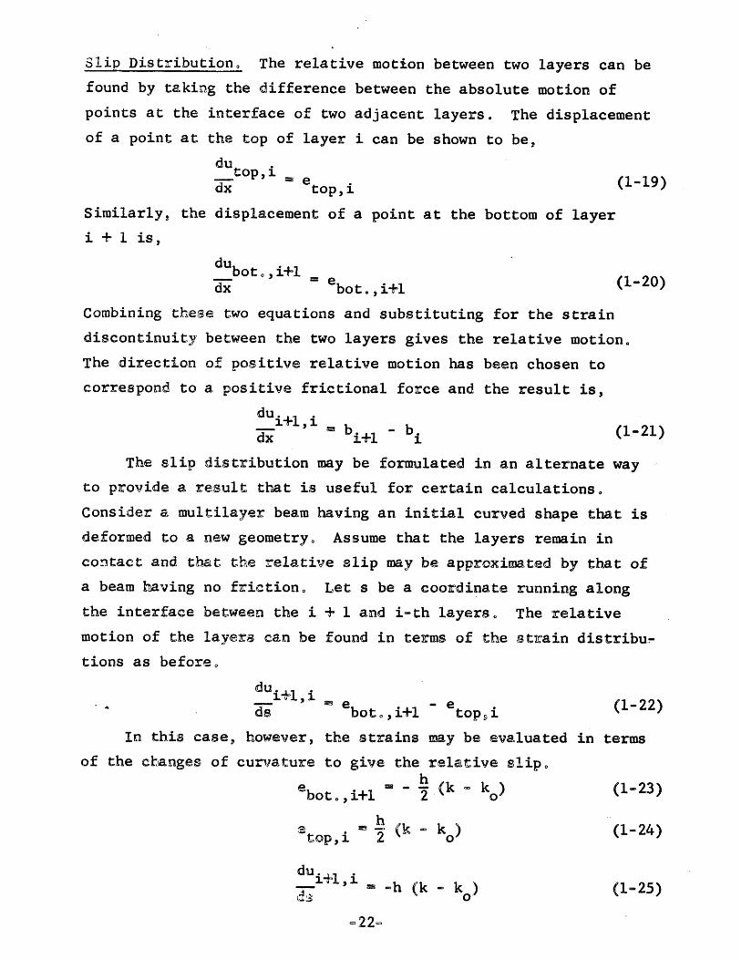
SB(1-~3 + ~(1-~)2(?f-U)J -Rg(1-u)2 - ~(1-U)3] 0<: u<~
.~~ (1-43)Sn(1-{f)(1-u)2 - ~(l-u)Jj -R[-~(1-U)2 - ~(1_U)3] 0<u<l
This equation is plotted on figure 1-6 for d = ~ and for.several values of Rls which is a measure of the relative effect offriction versus the imposed load.
As a check on the solution it is necessary to determinewhether the direction of relative slip at each point correspondsto the direction of friction force. Since the friction forcewas taken as being positive for the loading, cycle, the relativeslip must also be positive (based on the sign convention estab-lished previously). The slip distribution can be determined byfirst establishing the strain distribution from equation 18 andthen integrating this result in accordance with equation 21. Theresult is that the directions do not correspond for all pointsalong the beam and it becomes necessary to make a slight modifi-cation of the solution. This can most easily be done by usingthe method of equation 29 to determine slip direction. Applied
-32-
La>>Q
)a>
Lr-I
::l~
(/)
+-'(/)
CQ
)
nsL
U0-
L+-'
Q)
LOC
~.ns
nsa
+oJ-J
0)
(/)I
CII
C
-0)0
0+-'
(.),....-f
cd::l
0~
--ICD
't-+-'
0c
Q)
00
-a..
co.c..c.
(I)+-'
-0~
•Q
)
+J0Q)
,....-f
't-Q)
0
0<.0
0I
r-III
lOI.C
),....-f
N•
••
Ol
lL.
0LO
a,....-f
>k/)
0•
-33-

(1-45)
(1-47)
to this case the equation states that the slip will be positivewhen the slope of the deflection curve is negative. This meansthat the solution holds when all points on the beam, except at thewall, have negative slopes. This will be the case when the appliedload exceeds a certain level which depends on the frictional inter-action and geometry of the beam. This level of load can becalculated by finding the conditions under which the slope of thedeflection equation goes to zero in the interior of the beam.From equation 43 it can be shown that this slope goes to zero when,
I 2'R fl 2 J2(1-0') ....8 1"2 (l....u) ....(l""u) ~ 0 (1-44)The point of zero slope calculated from this equation must lieoutside of the beam itself for the deflection solution to hold.From equation 44 it can be shown that this is the case when,
s = V >_l_"",!",R (N-I)fkh (l_~2
At loads below the value indicated by this equation, theoriginal deflection equation does not hold and the deflection shapemust be computed by a different procedure. For positions u, whichdo not reach the point of zero slope, the beam acts as a solidbeam and the deflection curve for these positions is horizontal.For values of u greater than this, the original equation can beused with revised boundary conditions. Nevertheless, the originalequation still holds when the condition of equation 45 is satisfied.
A useful relation for experimental investigations of theproposed theory can be obtained by finding how the load varieswith the displacement at the point of load. This can be founddirectly from equation 43 by setting u =~.
V(y) => s[~(1-.n3] - R01-.1"t<2+?!1] (1-46)
In terms of force versus displacement this equation becomes,- [NEI~Q 3 ~ , 0 (2+?2JV - ---3- 3 f+ (N-1)fkh 2(1-0)L (1-0)
=34...

Where,s= displacement under the loado
This predicted force-displacement equation consists of twoterms. _The first represents the linear relation between forceand displacement which is obtained for a multilayer beam withoutfriction. The second represents the additional amount of forcewhich has to be added to overcome the frictional restraint. Duringunloading, the direction of slip reverses and the sign of thesecond term changes.
In accordance with the assumptions made in the analysis,equation 47 is valid only after the slip has propagated throughoutthe beam. The behavior preceding this condition consists of aninitial region in which the beam acts as a solid unit and atransition region in which the slip developso This will beconsidered in greater detail later.
Simply Supported Beam with Constant Normal Force--Experimental. Anexperiment was performed to determine the validity of the theoreticalrelations developed for the simply supported multilayer beam. Thiswas done by taking a number of strips of polyvinyl-chloride andsubjecting them to a normal force created by an arrangement ofrods and elastic strips as shown on figure 1-7.
Prior to the bending tests, measurements were made to determinethe quantities required for the theoretical expressions. Theresults were:
0.37 lb~in 2EIJ =N = 15L ::3 6 in.h = 0.028:-.' in.w == 0.50 ino
The one remaining value which was required--the friction forceper length--was measured separately for each normal force whichwas applied. The procedure used in making all the measurementsis described in detail in Chapter IVo This includes the preliminary
-35-
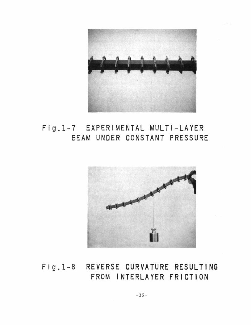
Fig.1-7 EXPERIMENTAL MULTI-LAYERBEAM UNDER CONSTANT PRESSURE
Fig.1-8 REVERSE CURVATURE RESULTINGFROM INTERLAYER FRICTION
-36-

measurements and the bending tests.Measurements were made of the force-displacement curve at
the point of loading. This was done for three different pressuresand for loads applied at varying positions along the beam. Athree-point loading as shown on figure 4-8 was used. The effectivecantilever length was half the total length, and the force-displacement curve was measured for the outside loads. Theloads were applied by means of an rnstron Tensile Testing Machinewhich imposed a constant rate of displacement.
The results showed that the relation between force anddisplacement was as shown on figure 9.
Friction ~Force Vf//
v
Force
~ DisplacementFig. 1-9 Typical Force-Displacement Curve Measured for
Simple Supported Multi-Layer Beam
The slope and friction force of each curve was measured forcomparison with the values predicted by equation 47. Thisequation can be rewritten in the following form.
-37-

Fig. 1-10 MUlti-Layer Beam Stiffnessvs Position of Load
EB
....... THEO RY
EXPERIMENTAL
E9 fk = 0
E8 fk = 0.398 Ibs/ in.& fk = 0.258Ibs/in.
4
3
O-------'-- ---L ...I-.- -.Io 0.2 0.4 0.6 0.8
1
dV 2en(lb/in)
-38-
1.0
0.8 EXPERIMENTt.L
£ fk = 0.398 Ibs/ in
EEl fk = O.258Ibs/in
0.4
0.2
THEORY
O':------:;:::--L..;:;-------,.~---__:__l~--__._Jo 0.2 0.6.8
Fig. 1-11 FRICTION FORCE vs POSITIONOF LOAD
-39-

Slope dV=- =def (1-48)
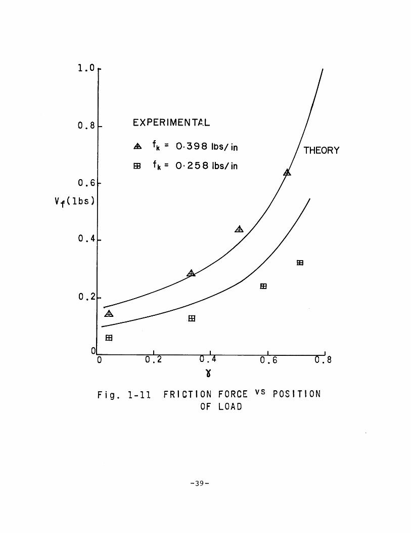
Friction Force = VF = 2(i~~fk(N-1)h (1-49)These quantities are plotted on figures 10 and 11 as functions
of o using the measured values of N, EI~, L, fk, and ho Themeasured values are plotted on the same graphso
Agreement between theory and experiment appears to be good.On the basis of the properties of the individual layers of thebeam, the interaction between layers, and the geometry of systemit was possible to predict the bending behavior. Note, however,that the predicted slope was independent of the amount of frictionalinteraction, whereas there was a difference between the measuredvalues. This indicates that the assumption that slip haspropagated through the beam and continues to do so as loadingproceeds is not entirely Justified. For this reason the propagationof slip was investigated in greater detail and will be discussedlatero
During the bending tests, some of the loaded beams werephotographed to measure the deflection curves. These measuredshapes were compared to the predicted shapes and the results areshown on figure 1-12. Here the parameters input to the deflectiontheory were the measured slope and friction force. Again, theresults indicate agreement between measurement and prediction 0 Note,however, that the measured reverse curvature was greater than thatpredicted. This may be due to the approximation made in settingthe curvature equal to the second derivative of displacement. Itmay also be due to a lengthwise variation in friction force causedby the applied loads.
propagation of Slip in Simply Supported Beamo The previousanalysis of the simply supported beam was limited to beams inwhich slip had propagated throughout the structure 0 In thisanalysis the nature of the slip propagation phenomenon will be
-40-

. 3
.2• 10
. 3c: . 20
....., . 10Q) 0
r-f't- • 3 0Q)
Cl .2CI)
. 1CI)
Q)
0r-fc:0 .3CI) .2 0 0c:Q)
E .1Cl 0> .3
.2
.10
. 3
.2
.10
Fig. 1-12 Theoretical and MeasuredDeflection Curves
u-41-

(1-50)
considered in detail in an attempt to determine the shape of theforce-displacement curve in the initial region 0 The basic principleto be used is that two layers will slide relative to each other whenthe shear stress tending to cause this movement exceeds the shearstress which can be resisted by static friction.
The analysis will be limited to the simply supported beamwhich has no overhang. (0= 0)0 This is, of course, the sameproblem as a cantilever with a point load at the end. The assump-tions which will be used are the same as those of the previousanalysis with the additional assumption that the static and kineticcoefficients are equal. The results for this assumption will beanalyzed qualitatively to determine the effect of differencesbetween the coefficientso It will also be assumed that slip willcontinue once it has occurred at an interface.
When the beam of figure 1-5 with ~= 0 iSlloaded, the initialshear stress distribution can be obtained from equation 35 by
..*letting.h = Nh. The maximum value occurs at the center. For aneven number of layers there will be an interface at this point andslippage will occur when the imposed stress equals the amountwhich can be resisted.
dk 8f=-~~dX1st EWh2N2
slipThe subscript has been dropped from the friction force term
because of the assumptions of equal coefficients of friction. Asthe load exceeds the point of first slip, the beam will behave astwo halves slipping at the center. Because of the slippage, thesurface force on each of these two halves will remain fixed at alevel corresponding to the friction force. The shear stressdistribution in each half will follow the form of equation 36
*with h = Nh/2.. This distribution increases in magnitude as theload increases and will continue to do so until a second interfaceattains a shear stress great enough to produce slip. This secondslip will be at the layers above and below the center of the beam
-42-

since the shear stress will reach the critical value first atthose locations. At this second point of slip,
(1-51)dk 8fdXind = Ewh1N(N-2)
slipFollowing this second slip the beam will consist of two slidinglayers in the center surrounded by two groups of layers that havenot yet slipped. As the load increases further, the slip propa-gation will proceed outward from the center until each layerslips. A general formulation can be made to define the point ofeach slip, using the same procedure as above. The result is,
dk- =dXj_thslip
j=l
[N-20-2)J 1[N-20_2) -2] j=2,3,4, ... ~
(1-52)
Alternatively, this equation can be written in terms of thenumber of layers sliding in the interior of the beam. Letting
S = number of layers sliding in center of b~am,
(1-53)
S-0,2,4, •..N-4
1st Slip1
N2
dkldXend of S=
layerssliding 8f 1
Ewh2 (N-S)(N-S-2)As the load increases and the slip propagates, the shear stressdistribution changes from the parabolic shape which exists at thepoint of first slip to one which levels out to a distribution ofsmall parabolic sections for each of the sliding layers. This isillustrated in figure 1-12.
-43-

y yy
a. At 1st Slip bo At Intermediate c. After CompleteStage Slip
Figo 1-13 Shear Stress Distribution Transition in Beam withConstant Shear Force
For the assumptions made here, it was possible to determinethe mode of slip propagation. Now it is necessary to compute theload-deflection behavior that the beam undergoes during each ofthe intermediate modes. This can be done by applying the equationsderived in the general analysis to the case of layers of varyingthickness sliding against a frictional restraint. The result is,
(1-54)
before 1st slipdk N3dx
v Ele :~ E+!<N-S)3J+ fhfNi']. S=0,2,4,6, ... N-4EIe :~ N + fh [N-l] after last slip
Each mode has a behavior indicated by the above equation.The relation between V and dk/dx is linear for each stage ofdeformation; and the slope gets progressively smaller while theV-intercept increases. This is shown qualitatively on figure 1-13.
-44-

Mode 1
v
dkdx
Fig. 1-14 Relation Between Load and Geometry for Each Mode.of Slip
In order to obtain the final behavior, the force-geometryrelation at each mode (equation 54) must be combined with therelation which gives the points of slip (equation 53). The resultof this computation shows that for the assumption of equal staticand kinetic coefficients of friction the points of slip corres-pond to the intersection of the load-geometry curves of equation 54and figure 1-13. This fact considerably simplifies the calculationssince the entire transition behavior can be defined by equation 54.Each individual equation holds until it intersects with the nextequation.
The transition can be written in terms of force versusdeflection by converting the derivative of curvature to thedisplacement under the load.
. .,
d3z dk--- = -- = constantdx3 dx
:~(L)= 0 = z(L)z(O) 3' ff = 1- dk
3 dx-45-
(1-55)

(1-56)c =
Before writing the final equation it is convenient to definetwo variables: the spring constant of a solid cantilever (c);and the total thickness of the beam (H).
3N3EI~
L3
H = Nh (1-57)Combining equations 54 and 55 and putting the variables in
dimensionless form gives the solution for the transition regionand the final behavior
(1-58)
before 1st slip
S=O,2,4, .•. ,N-4
after last slip
f~ ~
t 1 3JV "'.-£ S + li(N-S) J N+SHf fH N3 + 2N
--£... rLJ J + N-lfH lN2 N
Each line segment holds until its intersection with thenext segment, to give a single valued function V( J").
Equation 58 is plotted on figure 1-15 for various values ofNo This plot represents the force deflection behavior of a beamof constant total thickness and constant pressure that has beendivided into various numbers of layers. The intersection of eachline segment on this plot indicates a change from one slip modeto another. When the slip is complete, the beam follows thebasic equation used in the preceding analysis.
As the deflection of the end of the beam is increased, thepropagation of slip proceeds rapidly at first and then getsprogressively slower. This may be seen on figure 1-15 by observ-ing that the distance between intersection points increases withdeflection. At large deflections the slip propagation may not becomplete and yet the relation between load and deflection stillretains the same general form as found for complete slip. Inthis case, the friction force would be close to the final result,but the slope of the force deflection curve could be considera~ly
=46<=

oa
0Z<.0
LlJC
O~
0==~
Wa
a:>
N
LLW-J
za.-z
.-<
<0
-JllJ~Q
::llJ
to
.->-
r-f
Z<
W-J
~I
W0.-
<-J
-J:::l
0-
:;E:c
(I)0
0\t-
oW
~..........
I0
0
w«
vo
00
~-J
0LLLOr-fI~
LO
0>
LL
-47-

different. This may explain the deviations between measured andtheoretical results of figure 1-10.
In materials having differences between the static and kineticcoefficients of friction the mode of slippage may be differentfrom that computed here. Each time the maximum allowable shearstress is reached, and slippage starts between two layers, theshear stress on the surface of the layers will drop below thelevel required to initiate slip. Then the mode of slip propagationmay not be exactly the same as for the case which was considered.The second slip, for example, may be more than one layer distantfrom the center of the beam, depending on the current shear stressdistribution relative to the locations of the interfaces. Thenthe modes of slip propagation will be considerably more complicatedthan for the case considered here.
Another effect of differences in the coefficients of frictionis that the points of slip will not correspond to the inter-sections of the load deflection curves of each mode. The beamwill follow the curve for a particular mode and change to the nextmode beyond the intersection of the line segments. This will causea rapid drop in load at .the points of mode change and will givethe load deflection behavior a sawtooth appearance. In addition,the beam will remain in one deformation mode for greater changesof end deflection.
The analysis presented here defines the transition region fora constant shear force in the beam and slip was found to propagatethrough the thickness of the beam. In a later case, the questionof lengthwise propagation will be discussed in detail.Beam Loaded with Constant Bending Moment. Another example of theapplication of the proposed theory is the case of a beam subjectedto a constant bending moment. This type of loading can be producedin the center of a beam by four points of loading as shown onfigure 1-15. For the purpose of this analysis the central regionwill be taken as being under a constant pressure and the regions
-48-

in which the point loads are applied will be taken as being underzero pressure.
Using the same symmetry condition as before the beam willbe replaced by a cantilever-having a two-point couple ~t the end.This is shown on figure 1-16 together with the definition of thevariables to be used in the analysis.
v
v v
v
Figo 1=16 Four Point Loaded Multi~Layer Beam UnderConstant Pressure in Central Region
The assumptions made in this analysis will be the same asthose made for the simply supported beam. In this case the shearforce maintains a constant value in the initial region of the beamand falls to zero in the central region. The friction force, onthe other hand, is zero in the initial region and constant forvalues of x', between a and L. Substituting this information intoequation 16 gives the differential equation for the curvature
-49-

distributiono
dkdx
=h(N-l)fkNEI~
O<x<a(1-59)
Solving this equation gives,
(;-xk ~1::::-1)fkX + h~N-l)fa + Va
( NEI9 NEI9 NEI9
O<x<a
a<x<L(1-60)
(1-61)
Note that the curvature varies in the region of constant moment.This is in sharp contrast to a classic beam where the curvaturewould be constant 0
The average curvature (k) in the constant moment region canbe determined from equation 600 The result is,
k ~ ~ _ h(N-l)fk(L-a)NElr 2NEl9.
Solving the equation for the imposed bending moment (va)and writing the result in terms of the length of the centralregion gives,
(1-62)
This equation expresses the moment~curvature relation forthe multilayer beam under considerationo It ~educes to theclassical result of a zero friction beam when the second termvanishes 0 However, when the second term exists, the beh~viorfollows the same pattern as in the simply supported beam.Elasticity produces a linear relation between load and deforma-tion to which is added or subtracted a constant term that dependson the frictional effect 0 This term is added during the loadingcycle and subtracted during unloadingo
In both types of loading situations considered, the frictional
=50=

-t-JCQ.)
Eo
~
0>C
-0CQ.)
m
Curvature
/
Fig. 1-17 Effect of Sliding Frictionon Moment Curvature Relation
-51-

effect is dependent onthe beam length; and for this reason thereis no constituative relation which exists at every point of thebeam. In a textile structure, however, which under certain casesmay be considered as a number of multilayer beams in series,there is a constituative relation that exists when the size ofeach element of the structure is much smaller than the length ofthe sample under test.
The slope of the moment-curvature relation will be referredto as the "elastic rigidity" and the additive amount of momentwhich must be applied to overcome frictional effects will bereferred to as the "frictional moment"" For this case the elasticrigidity is merely the sum of the individual layer rigidities andthe frictional moment is a term related to the friction force,the number of layers, and the geometryo During unloading thedirection of slip changes and the sign of the friction momentbecomes negative. The hysteresis curve produced is shown onfigure 1-17.
The type of behavior predicted here corresponds to thatobserved for textile materialso7 There is a stiffening effectdue to friction, an energy loss due to relative motion and anon-recoverability from bending due to friction 0
Propagation of Slip in Beam with Constant Bending Moment. Thesolution of this loading situation was made with the assumptionthat the individual layers are free to slideo This limits theresults to the behavior beyond the transition region during whichthe slip is propagating through the structure 0 The transitionregion can be investigated in greater detail by determining themagnitude of imposed shear stress at every point of the beam andcomparing it to the stress that can be resisted by static friction.
In performing this computation an apparent paradox arises.On the basis of classica.l considerations of beams there is noshear stress in the central region of a four-point loaded beambecause the shear force is zeroo This is true for most of the

(1-64)O<x<a
a(x<L sMh
+ NEl~
2-h (N-l)f (x-a),k
hM xaNEl.Q
b. 1 - b.=1- 1
length of the beamo However, in a small region near the ends, ashear stress develops because of the discontinuous strain dis-tribution imposed on the beam section. This was discussedpreviously and it was shown that the maximum shear force per unitwidth imposed is given by equation 39. To use this equation thestrain discontinuity must be computed at the beginning of theconstant moment region. This can be done by integrating equation 18with the boundary condition of zero strain at the free end and theappropriate values of friction force in each region. The resultfor an interior layer within the range of slip propagation is,
b. 1 - b. = kh (1-63)1.- 1.
From the curvature function of equation 60 this can beevaluated in terms of position along the beam.
Where:L = extent of slips
This equation is valid for any length of slip propagationinto the beam. From equation 39 the imposed shear stress perunit width at the end of slip (x a L ) can be computed. At thisspoint the imposed shear stress Just equals the shear stress thatcan be resisted by the static frictional forces. The extent ofslip can then be calculated from equations 39 and 64.
at x = Lsfd . = f
)1 s
Mh - Nf 71h3. s
--1~2-L - a =------
s h2(N-l) fk
(1-65)
-53-

The extent of slip into the region of constant momentincreases with the imposed moment as expected. The slip region willstart propagating when sufficient moment is applied to cause initialinterlayer motion and will grow linearly with imposed moment untilthe slip has propagated throughout the beam. To characterizethis transitional region, the point of initial slip and the pointat which slip has propagated throughout will be computed. This isdone by evaluating the bending moment at the appropriate valuesof L - aos
(lc66)MIst = 12
slip
Point of Slip Initiation:L - a = 0s
Nf rfh2s
Point of Complete Slip Propagation:LBL - a =-s 2
(1-67)
Mendof slip
It is convenient to put these computed values in terms ofthe friction moment that has been determined for the constantmoment beam in equation 62.
1MF = 4 (N-l)fkhLB (1-68)
(1-69)
(1-70)
This transition region is shown on figure 1-17. For thestatic and kinetic coefficient of frictions about equal and forbeam lengths much greater than the layer thickness the slippage
-54-

begins propagating at very low levels of moments. When theimposed moment equals about twice the value of the friction moment,the slip will have propagated throughout the beam. Before thefirst slip, the beam behaves as a solid and after the completionof slip, the behavior follows equation 62.
The important difference between the transition region ofthe constant moment beam and that of the constant shear forcebeam is that in this case the slip propagates along the lengthof the beam, whereas in the other case it propagates through thesection of the beam. Furthermore, the development of shear stressin this case is a result of a discontinuous strain distributionwhile in the other case it is the result of the imposed shearforce 0
Recovery from Constant Curvature Band--Theoretical and Experimental.the previo~s applications of the multilayer beam theory the
emphasis was placed on the loading cycle. The unloading behaviorin each case could be predicted by reversing the direction of thefriction force. In this section bending recovery will be consideredin greater detail and the specific case in question will be a multi-layer beam under constant pressure bent to a constant curvature andthen allowed to recover .
.During bending it will be assumed that the slip has beencomplete. Then, when the load is released, the layers will reslipan amount dependent on the relative effects of friction andelasticity. The extent of the reslipping will determine the bend-ing recoveryo
Let:k . d (" -1)i = 1mpose curvature 1nk = residual curvature (in-I)r
Lb = total length of beam (in)ub ~ slippage during bending (in)ur := slippage after recovery (in)
-55-

e. = strain during bendingl.
e = strain during recoveryrx = coordinate along beam measured from left
edge (in)xr = point where final slip equals original slip (in).
From the assumption of complete slip during bending, theinitial strain distribution on the interior layers can be foundfrom equation 18 to be,
ei = ky - kYi (1-71)The relative slippage can be computed from equation 21 and
the symmetry condition which states that the slip is zero at thecenter of the beam.
ub '" kht~ - 0 (1-72)
Upon release of the load, the layers will reslip from edgesinward. This will continue until the res1ip is zero. At thispoint (denoted by x ) the relative layer motion will be equal torthat originally imposed. Within the region of the beam where noreslippage occurs, the residual curvature will be equal to thatimposed. Considering only the left side of the beam, this may bewritten as,
(1-73)
Within the res lip region the relation between geometry andload may be expressed by equation 16. The friction force will benegative due to the reverse direction of slip and the shear forcezero because there are no externally applied loads.
h(N-l)fkNEI,Q (1-74)
Since the residual curvature is zero at x = 0, equation 74 canbe integrated and combined with equation 73 to give the result,
h(N-l)fk xO<x<xRNEI,Q
~= Lb (1-75)xR<x<.r
-56-

is,
The remaining portion of the strain distribution can be cal-culated for an interior layer from equations 5 and 74. The result
-h(N-l)fkyixbi = NEI~ 0 <x <: xR (1- 76)
From this equation the slip distribution after recovery can becomputed using the results of equations 76 and 21.
u =R
- x )R
(1-17)
Plotting equations 72 and 77 on figure 1-18 for the full beamlength shows the distributions of slip before and after releaseof load,o
u
--bent-""""'''':>''..--- released
x
Fig. 1-18 Slip Distribution Before and After Releaseof Load
-57-

(1-78)
The point at which the final slip'equals the original slipcan be obtained from the strain distributions. At this point thestrains will be equal and it can be shown that,
NEI.9. kIxR =h(N-I)fk
This equation can be used to determine the residual curvaturedistribution by substituting into equation 75. Then, averagingthe residual curvature over the length of the beam gives,
(1-79)
(1-80)
occur in a solid beam bent the same amount.k*I(1 - 4F )
This can be written in dimensionless form by multiplying each ofthe curvatures by the .half-thickness of the beam. The resultingdimensionless curvature represents the maximum strain that would
The result is,
Where,(1-81)
(1-83)
(1-82)* - Nh~= ~2= L(N-1)fkLb (Nh)
F - 4NEI 2~
Equation 80 is plotted on figure 1-19 for several values ofthe dimensionless parameter F. This quantity represents ameasure of the relative amount of friction to elasticity in thebearno Note that it is composed of terms previously introduced in
-58-

Q)
L.
:J~
.q-a
C'CSa
(Y)
Nr-I
,......>
a0
0•
L.
a•
•:Jc...lE
IIC'CS
La..""O
m0
mal
UJOL
.0-0)
00
E~-ro--J
UJI
>.-+-'D
0Q
)...-fL
.:J(0
:J~+-'c
oL
.D
0>0
*L
.'t-:J
~(.)
0
r-feu~
:J'"tJ
0CJ)
>0-Q
)L
.n:
0..--4
co(Y
)m
euN
..--4.c.
00
>+-'
aa
t-N
r-fC
••
aI
Q)
aa
•r-4
EII
II•
L.
C)
Q)
LLlJ...
0-
IL><
00
wCD~
Na
aa
*a
••
L.
•~
-59-
the analysis: the friction moment; the elastic rigidity for completeslip; and the half thickness of the beam.
The results of the recovery prediction show quantitativelyhow a multilayer beam with friction displays a non-recoverabilityfrom bending even though none of the individual components havebeen permanently deformed. This structural non-recoverability isalso found in textile structures as will be shown in Chapter III.
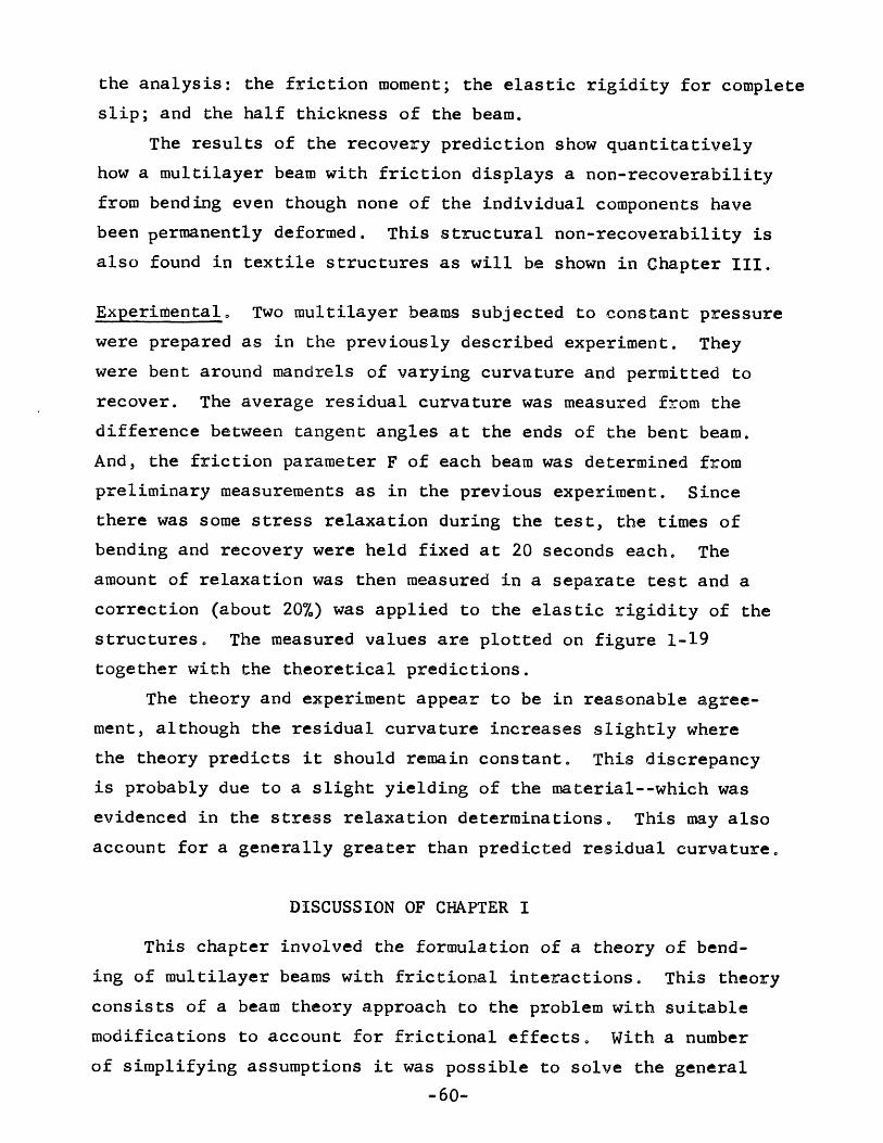
Experimental 0 Two multilayer beams subjected to constant pressurewere prepared as in the previously described experiment. Theywere bent around mandrels of varying curvature and permitted torecover. The average residual curvature was measured from thedifference between tangent angles at the ends of the bent beam.And, the friction parameter F of each beam was determined frompreliminary measurements as in the previous experiment. Sincethere was some stress relaxation during the test, the times ofbending and recovery were held fixed at 20 seconds each. Theamount of relaxation was then measured in a separate test and acorrection (about 20%) was applied to the elastic rigidity of thestructures. The measured values are plotted on figure 1-19together with the theoretical predictions.
The theory and experiment appear to be in reasonable agree-ment, although the residual curvature increases slightly wherethe theory predicts it should remain constant. This discrepancyis probably due to a slight yielding of the material--which wasevidenced in the stress relaxation determinations. This may alsoaccount for a generally greater than predicted residual curvature.
DISCUSSION OF CHAPTER IThis chapter involved the formulation of a theory of bend-
ing of multilayer beams with frictional interactions. This theoryconsists of a beam theory approach to the problem with suitablemodifications to account for frictional effectso With a numberof simplifying assumptions it was possible to solve the general
-60-

equations for several special cases. Then, a number of experimentswere conducted to establish the validity of the proposed theory andtreasonable\8.g:lreementwas obtained with the measured values.
The important qualitative conclusions that were reached arethat the effect of friction in a multilayer beam is to requireadditional loads to be applied to achieve a certain deformation.This occurs because friction either prevents the relative motionof the layers or else provides a restraint against this motionfor which additional input energy must be supplied. When the layersslide against a restraint, the load deflection behavior is non-linear, energy is lost in the structure, and recovery is notcomplete even when the individual layers behave elastically.
A number of interesting effects were observed theoreticallyand experimentally 0 The most striking of these is the reversecurvature that occurs in a cantilever which is under a normalpressure and loaded by a point load between the wall and itsfree edge. In this effect the region of the beam between theload and the free edge curves in a direction opposite to that
'.
of the main portion of the beam. ~ beam without relative motionagainst a frictional restraint would be straight in this region.
Another interesting effect is that the behavior of a beamwith friction may be dependent on the length of the beam. Thismeans that a constituative relation cannot be established betweenmoment and curvature at each point such as is done in classicalbeam theoryo For example, in the case of a beam bent with aconstant bending moment, the curvature will vary along the lengthof the beam and the extent of this variation will depend on thebeam length as well as the frictional force.
The applications of the work presented here may be appliedto a number of situations that arise in engineering technology.Examples of this would be such things as laminated structures,devices for generating unusual motions, structures for dampingvibrations, and combination spring-dampers.
As mentioned in the introduction, there are a number of-61-

aspects of the mechanical behavior of multi-layer beams thatcorrespond to observable phenomena in textile materia1so Inboth cases friction between the elements causes a stiffening ofthe structure; a non-linearity in the bending behavior energy lossdue to structural interactions; an increased level of strain; anda non-recoverabi1ity of the structure.
In textile materials, it is possible, under certain circumstances~to consider the structure to be composed of series of mu1ti~layerbeams. Then, even though no constituative relation may be establishedfor a point on the elemental beam~ one can be established for thetextile structure provided there are a large number of elemental beamsin the length of bend. This is in effect a continuum approachto the bending mechanics of texti1eso
When considering a textile to be composed of a series ofbeams, the curvature of the textile depends on the angulardeflection of each sub-unit. Since average curvature provides ameasure of angular deflection between the ends o~ a beam, thisquantity was utilized in the analysis, even though it is not usuallyof interest in engineering problems.
The analyses presented in this chapter represent one of thefirst approaches to the problem of the mechanics of mu1ti~layerbeams with frictional interactions. Additional research in thisarea with fewer simplifying assumptions would undoubtedly befruitful in the development of a complete understanding of thistype of structure 0 It is hoped that the material presented herewill provide a useful starting point for such investigations.
-62-

CHAPTER IITH~ EFFECT OF FRICTION ON THE BENDING OF TEXTILE STRUCTURES
In this chapter the effects of friction on multi-layer~dstructures will be extend~d to include textile materials. Thegeneralizations established for multi-layered beams will beutilized wherever possible and new approaches will be developedwhen they are needed.
In the first section several classical methods ofanalyzing the bending behavior of textiles will be discussed.These analyses consider only the limiting cases of frictionalinteractions. The next section contains a mostly qualitativediscussion on the intermediate frictional effects that areactually found in many textiles. In this section a conceptualmathematical model is developed from which the bending behaviorof textiles can be described by two parameters.
In the sections that follow, computations and experimentalresults are presented to establish these parameters for anumber of different types of textile structures. In addition,some general formulations are presented which pertain to therelative motion of fibers and yarns in textiles that may beuseful for areas of textile technology not related to bending.
LIMITING ANALYSES FOR THE PREDICTION OFBENDING BEHAVIOR OF TEXTILE STRUCTURES.
A number of investigations have been conducted withthe aim of predicting the bending behavior of textilestructures7,8,l7,l8 The goal was to relate the bendingbehavior of a particular structure to the properties of thecomponent fibers and their geometric arrangement.
As a first approach to the problem, the classical methodhas been to compute the limiting situations that can exist.These limiting cases can be established by considering two
-63-

possible forms of fiber interactions: complete freedom of fibermotion, and no freedom of fiber motion. In both cases it isgenerally assumed that the fibers deform as linear elasticelements. Then, for small deflections, the moment=curvaturebehavior will be linear and can be described by the slopeof the curve which is, of course, the rigidity.
For the case of complete freedom of fiber motion, theoverall behavior of a structure is determined by assuming thatthere is no interaction between the fibers which will causethem to develop axial stresses. Then, the total moment actingon a structure can be computed by vectorially summing theindividual bending and twisting moments on each of the fibers.If all the fibers are aligned perpendicular to the axis ofbending, the total rigidity for this case will merely be thesum of the individual fiber rigidities.
In the case of no freedom of fiber motion, it is assumedthat the interactions between the fibers are of sufficientmagnitude to prevent any relative fiber motion or fiber buckling.Then, the structure will deform as a solid material and havea linear strain distribution across the section perpendicularto the axis of bend. These strains will develop stresses inthe fibers which can be computed by considering the orienta-tion of the fibers relative to the axis of bend, and assumingthat each fiber carries. only axial loadso This was done forthe case of a twisted yarn by Backerl~ The rigidity of thestructure can then be determined by integrating the stressdistribution at a fixed curvature. If all the fibers areperpendicular to the axis of bend, the rigidity will beapproximately that of a solid material having the same modulusas the fibers.
Clearly, the rigidity computed by each of the two limit-ing analyses depends on the number of fibers in a section of
-64~

Df = fiber diameter (in)D = yarn diameter (in)y
(lb/in2)E = tensile modulusI. = moment of inertia of fiber (in4)
~(in4)I = moment of inertia of yarny
N = number of.fibers in yarnf~y = packing factorM = bending moment on yarn (in/lb)k = yarn curvature (in-I)
For the case of complete freedom of motion, the
the structure, the rigidity of each fiber, and the geometryof the system. The result for the assumption of no freedomof fiber motion will be considerably greater than that forthe assumption of complete freedom of motion and this isillustrated qualitatively on Figo 2-10 The magnitude ofrigidity will be computed for the limiting cases of certainstructures in this sectioDo Then, in later sections, theintermediate cases of frictional interaction will be consideredto determine the actual moment-curvature relation for certainstructures.Limiting Rigidities for Zero Twist Yarn. The rigidity of azero twist yarn can be computed for the two cases of freedomof fiber motion using the above methods. It is assumed thatthe yarn cross section is round and that the packing offibers is constant. Let,
bendingmoment on the yarn will be the sum of the individual fiberbending moments. If the radius of curvature is small relativeto the diameter of the yarn, then all of the fibers will bebent approximately the same amount and they will each haveapproximately the same bending moment. The moment-curvaturefor this case can be written as,
M = Nf Eli k (complete freedom,-'ofmotion) (2-1)
-65-

+-'c:Q)
Eo
~
enc
"'0CQ)
m
No Freedom ofMotion~ ~ Nf2 Eli
Complete Freedomof Motionf~Nf EI i
CurvatureFig. 2-1 Limiting Conditions of Freedomof Relative Fiber Motion
-66-

Since this equation can be used to give a good estimate ofthe bending rigidity of a large number of textile materials,it is useful to rewrite it in terms of quantities commonlyused in textile terminology 0
(2-2)
(2=4)
(2=3)
Where:Eg = fiber modulus (gms/denier)UJ = fiber linear density (denier)~ = fiber density (gm/cc)M/k = yarn rigidity (lb-in2)
For the case of no freedom of motion the rigidity canbe determined from the rigidity of a solid rod corrected forthe packing of the fibers. Since all the fibers lie perpen-dicular to the axis of bend, orientation effects need not beconsidered 0 The moment-curvature relation for this case is,
M = EI kYThe yarn moment of inertiai,can be written in terms of the
yarn diameter and packing factoro The result can then berewritten in terms of the fiber diameter and packing factor 0
?f 1TD 4 N211 D4I = Y y = f
Y 64 cr 64yThis equation can be used to determine the final relation
in terms of the individual fiber rigidity,N 2
M = ~ Eli k (no freedom of motion) (2=5)From equations land 5 it is clear that the rigidity for
no freedom of motion is about Nf times as great as that forcomplete freedom of motion. Since Nf is of the order of 100for many yarns, there is considerable difference between therigidity in both cases. Note that in the multi=layered beam
-67-

analysis of Chapter I, the results indicated a factor ofNi between the rigidities of the limiting caseso Thedifference arises because in one system fibers are the individualelements and in the other, layers.
Limiting Rigidities of a Twisted Yarn. The limiting casesof rigidity of a twisted yarn can be computed by consideringan idealized yarn made of helically arranged fibers 0 Thecomplete freedom of motion rigidity can be determined byvectoria1ly summing the moment contributions on the individualfibers at one cross section. The no freedom of motionrigidity can be determined by integrating the tensile stressdistribution across the section and correcting for theinclination of each of the fibers.
Both limiting cases were solved by Platt8 in an analysiswhich was quite involved because of the complex geometry ofthe structure. Nevertheless, he was able to solve the equationsby making suitable approximations, and he obtained resultswhich are valid up to helix angles of about 30°0 Theseresults may be written in the same form as used in the previoussection~
Complete Freedom of Motion (2=6)
Where,
N 2M = ~f Elif2(Q) K No Freedom of Motion
y(2=7)
t~= OUiSide he~~ angle 4 ~~ 2 J_ ~nesec Q - 3 S1n Q + (I-cos Q) tan QcosQfI(Q) ~ 2 (1 = cos Q) 2(1 ~ cos Q) (2~8)
-68-

E~esec2Q - 2Sin2Q~~tan2QCOSQ]f2(Q) = 4 (2-9)
tan Q (1 - cosQ)It can be shown that the values of both functions
fl(Q) and f2(Q) are unity for zero helix angle and the resultsreduce to the solution of the zero twist yarn. As the helixangle increases, both functions fall slightly, and eachreaches a magnitude of about 0.75.at 30°. This means thatthe effect of the helical configuration of the fiber issmall on the.bending rigidity.of the yarn. The maximum changeof rigidity due to this effect is about 25%, whereas the changeof rigidity due to differences in freedom of motion caneasily be a factor of 100.
A similar result was found by Owens7 for the case ofcomplete freedom of motion. His approach was considerablydifferent from that of Platt, but the results are insurprisingly good agreementl9 .
In addition to a direct geometric effect on rigidity,~he twist can also influence the degree of relative fibermotion. Since the geometric effect is small, it is probablethat the major effect is the change of internal yarn pressureand relative fiber motion with change of twist.
Limiting Rigidities of a Bonded Fabric. Although bondedfabrics have a considerably different structure from the yarnsconsidered in the previous sections, it is possible to computetheir limiting rigidities by the same general procedures.This was done by platt and Freestonl8 for a bonded fabrichaving an arbitrary angular distribution of the fiberorientations. When the equations are applied to the case ofa random laid non-woven,. the results can be written in thesame form as before. The conversion of Platt's equations tothe form used here is shown in Appendix B.
-69-

Complete Freedom of Motion (2-10)
No Freedom of Motion (2-11)Where,
Nf = number of fibers in section having a width equalto the fabric thickness.
5 = factor dependent on fiber torsional properties(between about 1.2 and 1.3)
0; = approximate packing factor of bonded fabric.Note the similarities between the limiting rigidities for thebonded fabric and the yarn structure. For this material,there is an additional factor of about 0.5 in the equation andthis accounts for the fact that the fibers are not all per-pendicular to the axis of bend. The ratio of rigidity forthe limiting cases is almost the same as before.
Experimental investigations have shown18'~~at the behaviorof bonded fabrics approaches the predicted values for nofreedom of motion. This results from the bond points betweenfibers which act to restrict relative fiber motion.
Twisted yarns and most fabrics on the other hand behavevery close to the predictions of complete freedom of motion.This can be demonstrated qualitatively by applying treatmentssuch as starch and observing large increases of rigidity.
QUALITATIVE EFFECTS OF FRICTIONON BENDING BEHAVIOR
In the preceding section, predictions of bending behaviorwere made for the limiting cases of fiber interaction. Theresults indicated that there are large differences betweenthese cases and the problem at hand is the determination of
-70-

the bending behavior for intermediate values of frictionalinteraction.
This was done in Chapter I for multi-layered beams. Itwas found that inter-element friction produced: a stiffeningof the structure; a non-linearity in the moment-curvaturerelation; an energy loss in bending; and a non-recoverabilityfrom bending. Quantitative determinations of these effectswere made by an analysis of the equilibrium requirements ofthe structure. The results indicated that friction affectsthe bending of multi-layer structures in two ways; it preventsthe elements from sliding by each other as much as they wouldif there were no friction; and it requires that energy belost where sliding takes place.
In Chapter I it was also found that friction couldrestrict sliding by either preventing slip propagation through-out the cross-section of the structure, or by preventing itspropagation throughout the length of the beam. This lack ofslip produced an increase in rigidity but had no energy lossassociated with it.
It was also found that friction had an effect in theregion of the beam where sliding did occur. The slidingfriction forces required an additional moment to be appliedto the structure during bending. This is illustrated onFig. 1-16 as is the energy loss associated with this frictionaleffect.
On the basis of these results a conceptual model can beconstructed which is useful for analyzing the bending behaviorof textile structures. This model, which is shown on Fig. 2-2,consists of an elastic element in parallel with a dry-frictionalelement. The load-deflection or moment-curvature relation forthis model is shown by the straight lines on Fig. 1-16. Theelastic term increases linearly with load while the friction
-71-

ElasticElement Dry
FrictionalElement
Fig. 2-2 Conceptual Model ofFrictional Effect
-72-

(2-12)
term is constant and always acts opposite to the direction ofloading.
This conceptual or mathematical model requires two para-meters for its description: an elastic parameter which willbe called the'elastic rigidity; and a frictional parameterwhich will be called the friction moment. The magnitude ofthese quantities are functions of the geometry and propertiesof the elements of a structure. The elastic rigidity dependson the degree of freedom of fiber motion and the frictionmoment depends on the amount of energy lost due to slidingfriction. One method of computing the friction moment whichhas been found convenient for the analysis of textilestructures is shown in the following equation,
'~UIfM = -~--f 9'i<
Where,friction momentM =f
k =
~=f
average curvatureenergy loss per length of material dueto sliding friction.
This equation can be solved when both the slip distributionand the friction force distribution is known in a structurebeing bent. Upon integration, these functions determine theenergy loss per length.
Previous investigators have found the existence of afriction moment in the bending of textiles. Eeg~Olofssonl2,21found a hysteresis in the moment-curvature rela'tion whichmay have been due to frictional effects. In similar measure-'ments Isshi11 found a relation close to that shown on Fig.1-16 for cotton yarns and fabrics. owens7 talso observedfrictional moments on a n~mber of textile fabrics.
-73-

In addition to direct observations of friction momentsin textiles, Zorowski and Chen 10 found non-linearities inthe deflection behavior of gravity loaded cantilevers made ofply yarns. Their results could be explained in terms of afriction momento Similar measurements were also made by
13Swami and Grossberg ,using fabric samples 0 They determinedfriction moments by both cantilever and buckling tests andrelated the measured values to certain properties of thematerials.
Since friction can effect bending behavior by eitherpreventing complete slip or by producing a restraining forceagainst slip, it will effect both the elastic and thefrictional parameters of this madelo At low frictional effectsthere will be both low elastic rigidity and low friction momentoAt very high frictional effects,which are close to the case ofno freedom of motion, the elastic rigidity will be high, butthe frictional moment will again be lowo In the first casethe friction moment will be low because the frictional forcesare low; and, in the second case, it will ,be low because therelative fiber motion is amallo At intermediate frictioneffects, the elastic rigidity will be moderate and the frictionalmoment will reach its maximum valueo
A number of modifications can be applied to the funda-mental model of Figo 2-2. For example, combinations of thistype of element can be used to account for such effects asvariability of properties or frictional interactions. Or,it is possible to include time dependent elements in themodel to account for the visco-elastic properties of fibers.This will not be done in this investigation but wouldcertainly be of value for further research on frictionaleffects on bending.
-74-
FIBER MOTIONS DURING BENDINGIn the preceding section it was shown that the frictional
effects in textiles are directly connected with the relativefiber motions 0 The extent of these relative motions dependson the amount of frictional interaction and the amount ofmotion required to map out the bent configuration of thefiber assembly. In this section two analyses will bepresented from which it is possible to determine the relativefiber motions for a number of situations. The results willbe applied in the later sections of the thesis.
In Chapter I two methods were derived for computingrelative motion between the layers of a multi-layer beam.(Equations 21 and 28.) These methods are based on straindiscontinuities of parallel layers in intimate contact.Although the results are useful for fiber systems havinglayered arrangements, they cannot be applied to more compli-cated cases such as twisted yarns or randomly arranged fibers.Consequently, additional methods were established and will beincluded in this section.
The equations which describe the relative motions offiber have applications in fiber technology not necessarilyrelated to bending. Examples of this are drafting, fibermigration, fabric abrasion, and jaw penetration during tensiletesting. Perhaps the equations developed here can later beapplied in some of these areas of research.
Continuity Equation for Fiber in a Deforming Structure.When a textile structure deforms, the component fibers arerearranged or distorted in some manner 0 The fibers may eitherstrain, move relative to the structure, or buckle. Theseactions can occur separately or in combinations 0
-75-

As an example, consider a yarn bendingo There are anumber of possible changes of fiber configuration that cantake place. If all the fibers are cemented together, thefibers will undergo tensile deformations but will not ~lip orbuckle. If, on the other hand, the fibers are free to slide,they will not develop a net tension or compression, but willslide relative to the structure and possibly buckle. Here,the term buckling refers to a departure of the fiber from theassumed geometric configuration. For example, the fiber mayfollow a helical path before bending and then deviate into anon-helical path after bending. The particular type offiber rearrangement occurring in any situation clearly willdepend on the interactions between the fibers. However,from the condition of continuity there are only a limitednumber of possible fiber rearrangements for any situation. Andthis may be expressed mathematically in the form of a continuityequation.
The continuity equation will be written in terms of acoordinate system defined by the yarn axis. It can easily berewritten in terms of a coordinate system defined by a line inthe center of a fabric or any other convenient systemo Let,
5 = coordinate measured along yarn axisoLl = fiber length in length of yarn from 0=8 at
state 10
L2 = fiber length in length of yarn from 0=8 atstate 2.
u = fiber length moving through yarn cross~sectionyin change from state 1 to 2.
ef = fiber strain.Consider a control volume defined by two planes perpen-
dicular to the yarn axis at locations sand s + ds. As theyarn axis deforms from state 1 to state 2, the fibers will in
-76-

general move through these planes by a certain amount. Thismovement will be referred to as fiber motion relative to thestructure. The motion of two fibers relative to each othercan then be computed by taking the difference between theirmotions relative to the structure.
The relation between slip and strain of a fiber can befound by a conventional continuity approach for the controlvolume shown on Fig. 2-3. Note that a partial derivative isused to avoid confusion with the change of slippage withcurvature.
\\\
,I '--~" •.- ---+ -.I "~_
\ I." \ I
/~~I-----I ----\ .
\ I .
State 1 State 2
(2-13)
Fig. 2-3 FIBER SLIP AND STRAIN IN.'DEFORMING STRUCTURE
-77-

The continuity equation can be specialized for certaincases to obtain solutions. This is done by specifying thegeometric states of the system in terms of functional rela-tions between Ll, L2 and s. This will be demonstrated fortwo types of systems, a bent twisted yarn and a bent layeredstructure.Twisted.Yarn. In this case it is assumed that the fibergeometry is helical (with constant rate of rotation aroundyarn axis) in both the straight and bent yarn. A coordinatesystem can be defined from the yarn axis with,
s = coordinate along yarn axisr = fiber radial position8 = fiber angular position measured from inside
of bendLt = yarn length per turn of twist.
Now the fiber length functions can be written for the caseof a yarn straight in state 1 and bent to a curvature k instate 2. It will be assumed that the fibers do not buckleand that their path around the yarn axis remains helical.
dLl _ -I. Udr)2 2~e02-~ 1+- +r-ds ds ds(2-14)
d~; =-P{l _ rk cos 9)2 ~~Y+ r2 ~:r
For a yarn with no migration and a constant fiber rotationabout the axis,
r = constant (2-15)
e = Yr. s (2-16)LtFor this idealized yarn, the continuity equation is obtained
-78-

(2-19)
from equations 13 -16.
~C)Uy = (1 + £ )i +(dr)2 + r2 (de) 2' .';;s f \ds\ds
'., -'~l~rk cos e/ + (~~Y+ r2 (~:y' (2-17)
This equation relates the fiber slippage to the strain.It can be integrated directly for the two limiting cases offreedom of fiber motion. When there is no freedom of fibermotion, there will be no slippage and the equation reduces tothe following form,
2 ( ?2£ ( ) (l-rke) + ,(211r/Lt) No Freedom of Motion (2-18)f r,9
1 +~Tfr/LJ2This strain distribution has previously been established
17.42by Backer ~ for fibers at different radial positions and forvarying twist. He used a method based on differentialgeometry.
When there is-complete freedom of fiber motion, therewill be no strain and the continuity equation reduces to,
;:}U1= -y{ +(21{r\2 -~6. _ rk~)2 + (2i!r.\2 Complete
~s \Lt/ )I(J \ t) Freedom ofMotion
This equation cam be solved using the boundary conditionof no slippage at the inside of the bend, e = 0, which is apoint of symmetry. The result for radii of curvature muchgreater than the yarn radius is approximately,
,rkLtu = ---- sin e (2-20). y 211
The result re~~ces to that derived by Backer for lowvalues of twist.
-79-

The slippage is greatest at the sides of the bend andfalls to zero at the top, e ~~, which is also a point ofsymmetry 0 Since the conditions of symmetry require that slipbe zero at this point, it can be concluded that an idealizedyarn can bend with complete freedom of fiber motion and nostrains 0 Alternatively stated, an ideal yarn which bendswith no fiber strain maintains a fixed fiber length betweeninside and outside of the bendo This length of fiber movesrelative to the structure but does not have to strain orbuckle to map out the geometry of the bent yarno Thisfinding corresponds to derivations in differential geometryof the constancy of the path length of a single loop of
. 17 22a'yarn~-beforei.~andafter bend~ng ,An interesting observation can be drawn from equation 20.
From this expression it can be shown that the points of fiberslying on a plane perpendicular to the yarn axis before bend-ing will not lie on that plane after bending. In fact, thesefiber points will lie approximate1~ on a plane that hasrotated from the original plane 0 This is illustrated inFigo 2-40 Note that this situation differs consider~blyfor the case of no freedom of fiber motion where the pointson individual fibers always remain in the plane perpendicularto the yarn axis.
Another interesting observation can be drawn from thefiber motions of a bent yarn that may have some practicalsignificance. When two equally twisted yarns are side-by-side,during bending, there will be a considerable relative motionbetween the surface fibers. This effect does not occur foryarns with opposite direction twist.
In more complex cases the conditions of symmetry cannot-be satisfied without fiber strain or buckling. For example,in a yarn having fiber migration so that individual fibers
-80-

form a helix of varying radius, it can be shown that thelength of the fiber path between two symmetry points is notconstant during bending. This means that the fibers will haveto alter their path around the yarn axis during bending andbuckle; or they will have to strain at some points alongtheir length.
\
I
II
II
I
II\\
plane containing points offibers originally in ~lane
perpendicular to yarn axis.
Fig. 2-4 FIBER MOTION IN A BENT TWISTED YARN
The same situation holds true in structures of higherorder such as ply yarns and cables. In these systems thefibers may have to strain to map out the bent configurationmerely because there is no available path by which they canslide. This phenomenon represents a geometrically inducedstrain or buckling. It can also occur in simple layeredstructures under certain conditions. One such case is amulti-layer .beam that is cemented or clamped at the ends so
-81-

that no relative motion can occur at these points. Then, evenif the interlayer friction approaches zero, there will be norelative layer motion within the structure as it is bent.This results from the boundary conditions of no slip at theends which corresponds to the case of no slippage at thesymmetry points of a textile structure. The bent configura-tion of this multi-layer beam will then of necessity involvetensile strains and/or buckling of the layers; and the beamwill be much stiffer than a similar beam without an endrestraint.
From these considerations, it may be concluded that thebending behavior of a multi-element structure depends not onlyon the frictional interactions between the elements, but alsoon the geometric restrictions to relative motion between theelements.
Two-Dimensional Layered Structureo The continuity equationmay also be applied to layered structures which deform fromone state to another. The length functions can be determinedfrom a knowledge of the shapes of each state and from thedistance between the centerline of the structure and theelement in questiono Again, for the purpose of illustrationthe structure will be assumed to be a yarn, but this timecomposed of parallel layers of fibers. An example of thedeformation of this structure from one state to another wouldbe the bending of a yarn in a fabric 0 State one would corres-Hond to the original crimped path of the yarn and state twowould be the crimped and bent pa~h of the yarn in the bentfabric. Let,
kl 2(s) = curvature function describing path of yarn,axis in state 1 or 2.
= distance of fiber to yarn axis in state 1
or 20
-82-

(Z-2l)
Other variables as before.The differential relation between fiber length and yarn
length can be written as follows for the two states,dLl _
~ - 1 + rl kl (s)
dL2ds = 1 + rZ kZ (s)
Substituting into equation 13 gives the result,du~ = r1 kl - r2 k2 + ~f(l + rl kl)
(2-22)
(2-23)
(2-24) Only strain, no slip,no buckling.
This equation may be specialized as before for limiting casesof ~iber interactions. These specialized forms of thecontinuity equation illustrate how the change in geometricstates can be accomplished by fiber strains, fiber slippage,fiber buckling, or combinations of the three.
rl (k2 - kl)€ =-----f 1 + rl kl
du--.:i. = r (kl - k2) (2-25) Only slip, no strain,ds 1
no buc\<ling.
=kl (2-26) Only buckling, no strain,r2 rl k
2 no slip.Relative Fiber Motion. The slippage term of the continuityequation is based on the relative motion between individualfibers and the planes perpendicular to the yarn axis. Thismotion represents the relative motion of the fibers to the yarnstructure. For certain cases this motion will be the govern-ing factor in the description of frictional effects. Inothers, the relative motion between two adjacent fibers will
-83-

be of importance. The solution for the first case can beobtained by a direct application of the derived equation andthat of the second case can be computed by taking the differencebetween the values of relative motion of tW9 adjacent fibers.
The results for the two cases will be quite differentand 'generally differ by a factor on the order of the ratio offiber to yarn diameter. This difference can have a greateffect on the overall behavior of a yarn or a textile structurein general.
When the arrangement of fibers in a yarn or fabric ishigqly disoriented, the motion of one fiber can be thought ofas occurring through a med~um composed of a rand9m fiber mass.In this case the relative fiber motion can best 'be ,calculatedby considering fiber motions with respect to the-yarn structure.This is because the adjacent fibers will be different atevery point and will not necessarily move in the same mannera~ the fiber in question. The relative fiber motionscomputed in this way will be large and will result in largefrictional effects if they occur against a frictional restraint.This probably takes place in some needled fabrics 0
If the fibers are arranged in a highly oriented manner,aswould be the case in an idealized twisted or layered yarn,the relative fiber motion is much less than in the previouscase for a given amount of change of curvatureo This isbecause the relative fiber motion involves the movements oftwo adjacent fibers. Although the individual fibers maymove considerable amounts relative to the yarn axis, they willmove only small amounts relative to each other. For thisreason, the frictional effects for this type of system aremuch smaller than those of the previous effects when theinternal pressures are the same. On the other hand, highlydisoriented fiber systems often have a greater opportunity
-84-

v =x =sx =rfk =
for fiber buckling and in those cases there may be smallamounts of relative motion.
Effect of Friction on One-Dimensional Slip and Strain.In addition to the continuity equation developed in theprevious section, another fundamental relation may be obtainedby considering the propagation of slip into an infinite medium.This will be done for the case of a fiber which is held in sucha medium by frictional forces and displaced a fixed amountat the point of entry into the medium. To compute the slippageand strains that take place in this case, it will be necessaryto go beyond the point of using the conditions of continuityand utilize the equations of force equilibrium.
Consider a rectangular fiber extending into a semi-infinite medium as shown on Fig. 2-5. Using the coordinatesystem shown, let,
u = relative fiber motion during loadingrelative fiber motion during unloadingextent of slip into medium during loadingextent of reslip during unloadingsliding frictional force per length oneach side of fiber
f = static frictional force per length that cansbe exerted on each side of fiber
u = imposed displacement on end of fiber0v = residual,displacement at end of fiber0
after unloadingE = fiber tensile modulusw = fiber widthh = fiber thickness.
-85-

u
Fig. 2-5 ONE-DIMENSIONAL SLIP AND STRAIN PROPAGATIONINTO SEMI-INFINITE MEDIUM.
The problem in this case is to determine the nature andextent of slip and strain propagation into the infinite mediumwhen a force or displacement is applied to the fiber end.Qualitatively, it can be reasoned that the fiber will bothstrain and slip only a finite distance into the medium. Then,when the load is released, the fiber will slip back into themedium, but it will not do so completely and thereby leave aresidual deformation. This deformation will depend on thecounterbalancing of elastic and frictional forces and will beanalagous to the residual bending deformation computed for themulti-layer beam in Chapter I.
During the loadi~g cycle, a differential equation may bewritten for the displacement at a point of the fiber. Thisequation is obtained from the continuity equation for thiscase, the stress-strain relation, and the force balance foran infinitesmal element,
-86-

E, = _ duf dx
T = Ewh ef
2f +dT=O O<x<xk dx s
The boundary equations for this equation are,u(o) = u
o
u(x) = 0s
(2-27)
(2-28)
(2-29)
(2-31)
(2-32)
du _- (x ) -dx s.
'Tffs---Ew (2-33)
Note that one extra boundary cond;Lt:ion',islgiven and]:this permitscalculation of the extent of slip propagation. The boundarycondition which gives the strain at the point x is obtainedsby computing how much shear stress is developed in a solidwall of material subjected to a step distribution of strain.When this shear stress equals that which the material canjust withstand by static friction, the step distribution ofstrain will correspond to the strain used in the boundarycondition. The intermediate steps leading to this con-clusion are not shown, but they follow the same generalprocedure used in Appendix A.
During unloading, a similar differential equation canbe written for the region in which reslippage occurs. Inthis case, the sliding frictional force will act in the oppositedirection. The boundary' conditions for this equation arebased on zero tension at the fiber end and no res lip beyond the
-87-

point x. At this point the tension drop due to reslidingrwill produce shear stresses which can just be maintained by
the static friction forces. The magnitude of the strain atthe point is computed by a superposition of strain distribu-tions and a method similar to that used for loading.
d2v -2£k
dx2 =--Ewh
dV(o) = 0dx
v(x ) = u(x )r r
dv du 17£+ V )dx(xr) = -(x) + __ s(1
dx r Ew
(2-34)
(2-35)
(2-36)
(2-37)The solutions to the differential equations can be
obtained by considerable algebraic manipulation. They are,
Where,
u = (u - x F)(X )2 - (2u - x F) Ex )+ uo s x o. s x 0s s
f.;~ (x F)2(2V+V2)v = -(u -x F) x + Uo + ~s~ ~_o s x 2 8(u ...x F)s 0 s
-88-
(2-38)
(2-39)
(2-40)
(2-41)
(2-42)
(2-43)

The results are plotted on Fig. 2~~ for slip and reslip asfunctions of position.
u,v
uo
vo
~~---recoverable displacement
____ --~~- non-recoverable displacement
xrx s X ---:):fP-
Fig. 2-6 SLIP AND RESLIP IN ONE-DIMENSIONAL PROPAGATION
Two variables are of particular interest in this result:the length of slip propagation and the residual displacement.The length of slip propagation can be represented in terms ofthe parameters of the system and the imposed displacement.The result is plotted on Fig. 2-i for ~ = 1. This resultshows that the greater the friction is relative to the elasticforces, the less propagation. It also illustrates the natureof the dependence of imposed displacement on the propagationlength. Another relation of importance is the residual
-89-

Fig.2-7 SLIP PROPAGATION LENGTH vs ENDDISPLACEMENT
.001
x~....
100
80
60
40
20
10
-90-
fk/fs = 1F =1ffs/Ew
F = 1.0
20 30

II
,,,,,,,,,~
,....-f
oa
o;---------:o
=------..L
----~~
(Y)
Na ,........
-91-
-0IDenooa
E(Y
)
en>+JC-t-J
IDCEIDIDEOIDC\1
.r::.O
,....-f
a...........
C\10..
NO
,........en
::J0...-
enD
CJenQ)
~ex:>IN
•

displacement that remains after the load has been removed.This variable is plotted on Fig. 2-8 in terms of the samevariables as before and for v1= 1. Note that the residualdisplacements equal the imposed displacement when the elasticrestoring force is not great enough to cause reslipping intothe matrix. Beyond this point the residual displacement isclose to one-half the imposed displacement.
The analysis presented here was done in conjunction withMr. Harvey Plonsker, who is using the results in connectionwith a research project on fiber drafting. In addition tobeing of interest in connection with that problem, these resultsmay have application in the problem of slip and stretchingthat takes place in a stretch fabric garment during wearermotion. They could also be used to predict the degree towhich materials will slip into the jaws of a tensile testingmachine. Or alternatively how much pressure must be appliedto confine the propagation length to a fixed space.
Although the results do not give any direct informationon rending behavior, they do give a better insight into thequestion of slip during bending and reslip during recovery.Moreover, the results may be applied directly to the problemof bending by considering the infinitesmal element at the topand bottom of a layer in a multi~layer system. This infinitesmalstrip will behave as the fiber in this analysis if the curva-ture changes are small. The strain variable can then bereplaced by the local change of curvature if the layer bendswith no tension.
FRICTIONAL EFFECTS IN YARNSZero Twist Yarn. In most uses of textiles the yarns usedhave at least some twist inserted for either strength orgeometry requirements. However, the length of one tu~n oftwist is usually considerably greater than the length of the
~92-

repeating unit of the fabric. For this reason, it is oftenpossible to assume that the yarns have a negligible twistand that fabrics behave as though the fibers were arranged ina simple layered form.
For a yarn of this type the frictional behavior issimilar to that of the multi-layered beam discussed inChapter I. There it was shown that once the slip hadpropagated throughout the structure, the bending behaviorcould be characterized by an elastic rigidity and a frictionmoment. This can be done readily for a zero twist yarn ifit is assumed that the structure is under a constant normalpressure. This pressure can develop from such things ascross yarn interlacings in a woven fabric or fiber tensionsin a bent yarn.
Assuming that the yarn is bent by a pure moment andthat slip has propagated throughout the yarn length, theelastic rigidity will be the sum of the individual fiberrigidities and the friction moment can be computed fromequation 12. Let,
n = normal force per length at each fiberinterface
Df = fiber diameterk = curvature of the yarn centerlineu = relative fiber motionw. = frictional energy loss at each interface1
in yarn length LWt = total frictional energy loss in yarn length LL = yarn lengths = position coordinate measured along fiber from
center of bendN. = total number of fiber interfaces between1
layers
-93~

Nf = total number of fibersr = yarn height to width ratio.
The relative displacement between two fibers stacked ontop of one another can be determined from the strain discon-tinuity between the fibers and the condition of symmetry at thecenter of the bend as in Chapter I, equation 25. (Note thata correction may be applied to account for close packingeffects.)
(2-44)Since the fibers move relative to each other against
an assumed constant frictional restraint, the work lost ateach element of fiber interface can be computed by
dW. = J.J. n u ds1 . I (2-45)
After integrating, this becomes,Lj~
~~nDfkL2Wi = 2J.J<- n Dfk s ds = 4 (2-46)
oNote that the integration was broken into two parts
because of the change in direction of the frictional force oneither side of the bent yarn. This same procedure will beused in subsequent calculations. Summing the frictional workloss over all the fibers gives,
This equation can be differentiated as in equation 12,1
Mf = 4 Nifln Df L
(2-47)
(2-48)
If the fibers are arranged in an open packed rectangularsection, the number of fiber interfaces will be equal to thenumber of fibers less the number of fibers in one layer.
-94-

This can be expressed in terms of the height to width ratioof the yarn
(2-49)
(2-50)
This equation relates the frictional effect in zero twistyarns to the parameters of the system. Note that the resultis identical to that of equation 62 in Chapter I. In this casethe number of fibers is used in place of the number of layers;and, the force per length on each fiber is used in place ofthe force per length on each layer. Note also that thecomputation made here utilized the energy equation rather thanthe method of Chapter I which involved the equa~ions of forceequilibrium.
In the section on the bending of woven fabrics, theimposed pressure will be evaluated in terms of the structureand properties of the system and it will no longer be necessaryto include this unknown quantity in the equations.Twisted Yarn.. The frictional effect in twisted yarns canbe determined for situations in which the fibers are free toslide, but do so against a frictional restraint. In this casethe elastic rigidity will be given by equation 6 and thefrictional moment can be computed by the energy method ofequation 12.
In order to establish this frictional bending moment, itwill first be necessary to determine the relative fibermotions that occur as the yarn bends. If the yarn isassumed to consist of cylindrical layers of twisted fibers,there will be relative motion both between fibers of different
-95-

layers and fibers of the same layer as bending takes place.These relative motions can be computed from the geometry of thebent twisted yarn.
Relat~ve motion~ of fibers in adjacent layers can becomputed by first determining the relative motion of theindividual fibers to the yarn matrix and then computing therelative motions of these fibers to each other. Using theresults of equation 20 and considering two fibers at radialpositions differing by one fiber diameter, the result is foundto be,
(2-51)where,
Us = relative motion between fiber of the samelayer
ur = relative motion between fibers in adjacentlayers
Df = fiber diameterk = yarn curvatureT = yarn twistr = fiber radial position8 = position angle of point on fiber measured
from inside of bendQo = helix angle before bendingQ = helix angle after bendingLt = yarn length in one turn of twistw. = frictional energy loss per length at one
l.
fiber interface.or
The pattern of relative motion of equation 51 indicatesthat there will be a sinusoidal distribution of slip whichis zero at both the inside and outside of the bendo Theamplitude of this distribution depends on the yarn twist, fiber
-96-

diameter, and yarn curvature as shown. It is independent onthe radial position of the fiber.
Relative motion between fibers of the ~ layer resultsfrom a change in the local helix angle as bending progresses.The magnitude of this change has been computed by Backerand found to vary with fiber position as follows,
11
cot Q = (1 - rk cos 8) 211rT (2-52)
This equation has been rewritten in terms of the variablesused in this treatment. (See Appendix C). It indicates thatall fibers except those at the sides of the bend change theirhelix angle; and that the maximum increase is at the insideof the bend while the maximum decrease is at the outside.When two adjacent fibers of the same layer experience thischange in helix angle, they will slide by each other as shownin Fig. 2- .
Unbent Bent
Q
Fig. 2-9 RELATIVE FIBER MOTION DUE TO CHANGE IN LOCALHELIX ANGLE
-97-

The magnitude of this relative motion can be shown to berelated to the change in helix angle as follows,
Us = Df (cot Qo - cot Q) (2-53)Combining equations 52 and 53 gives the slippage distri-
bution for this effect.
(2-54)This relative motion is quite similar to that of equation
20. In this case, however, the relative motion is zero at thesides of the bend and reaches a maximum at the inside andoutside positions.
Since the relative motion of fibers is readily observable,an experiment was conducted to determine the validity ofequation 54. This was done with a large scale model of aseven-ply yarn (each model fiber being about 1/8 inch indiameter). In order to facilitate the interpretation ofthe variables in the slippage equation, it was rewritten indimensionless form.
(2-55)
In this notation the slippage is measured in units offiber diameters. The curvature is given in a dimensionlessform which corresponds to the maximum amount of strain thatwould occur in a solid elastic rod of equal size bent the sameamount. This dimensionless curvature was used in Chapter Iand will again be used in Chapter III.
Measurements were made to determine the relationshipbetween slip and curvature, and slip and fiber position.The results for both theoretical and measured values are givenon Figs. 2-9 and 2-10. Note that there is generally goodagreement for low curvatures. The deviations at the higher
-98-

0.1 0.2 0.3 0.4Ryk
Fig.2-10 RELATIVE MOTION BETWEEN FIBERSOF ONE LAYER OF A BENT YARN
THEORY
~I
II
I/
I/
EXPERIMENTAL /1/
/(f)//
////
/
/?f
//
/'
///
/ffl/
e = 180000 = 27°
o
1.5
1.0
0.5
-99-

.8 Rk = .20Qo = 27°
.6UsOf • 4
.2
-.2
-.4
-.6
-.8
3600 eTHEORY
Fig. 2-11 RELATIVE MOTION vs FiBERPOSITION
-100-

curvatures probably occur because of the mathematicalsimplifications made in the analyses.
The relative fiber motions that take place in a benttwisted yarn are given by equations 51 and 54. When theinterfiber friction resisting these motions is known, then itis possible to compute the friction moment by applying equation12. This will be done for two cases: in the first the internalpressure distribution will be assumed constant; and in thesecond it will be assumed to be the distribution resultingfrom a constant tension. In both cases the analyses willassume that the fibers are able to slip to the full extentand that frictional forces act against the motions ratherthan act to prevent them. In this case the elastic rigiditywill be as given by the result of the complete freedom of motioncase. If the frictional forces are sufficiently high toprevent.complete slip, then the continuity equation must beused to determine the effects of partial slip on elasticrigidity and friction moment. The case of partial slip willbe considered later for the woven fabric and those resultscan be applied hereo
Friction Moment in Twisted Yarn under Constant Pressure.Under the assumption of constant pressure the normal forceper length at each fiber interface will be constant. Thenthe frictional energy loss per length of yarn at one interface,'~.", can be computed. This is done by integrating the force-
~displacement behavior over one-half turn of twisto A halfturn is used because this length represents a repeating unitof the structure. ~~-
wi = 2T~niUdS (2-56)o
Note that the yarn length of one-half turn of twist is1/(2T) and the length of fiber in this amount of yarn is taken
-101-

(2-57)
(2-58)
to be approximately L /2. Since the normal force is assumedt
constant, equation 56 may be rewritten as:Lt
w. = 2!,t<.ni -2 u1 avg
L%,u a ~(S) dsavg J
(jSince the slippage distributions between and within
layers differ only in phase, the average values will be thesame. It should be noted that the integration of equation 58must be performed in such a way as to average the slippageover a region in which the frictional force remains the same.This must be done because the direction of this force changesso that it always opposes motion. The result may be substitutedinto equation 57 to give:
2 LtWi = 1l00iDf T k (2-59)
Summing over all the fiber interfaces N. and differentiating1
with respect to curvature gives the friction" moment,
2 LtMf = 1T2A 0i Ni Df (2") (2-60)
This equation corresponds ~10se1y to the friction momentpredicted for a zero twist yarn by equation 50. In this casethe characteristic length of the system corresponds to theaverage length of fiber in one-half turn of twist, whereasin the other it corresponds to the sample length.
If it is assumed that each fiber contacts two fibers inits layer, two fibers in adjacent layers, and the number offibers in the yarn is large, then:
4 LtMf =< 112 N~oi Df T (2-61)
-102-

Equation 61 gives the functional relation predictedwithin the assumptions of this analysis. The normal forcebetween fibers has been left in general terms. It will dependon the equilibrium configuration of the fibers, the yarn tension,any lateral loading which may exist, and the yarn twist.
It should be noted that this equation assumes that thelength of yarn being bent is much greater than the twistlength. If the test length is smaller than the twist length,then the yarn will behave as predicted by the zero twist analysispreviously presented. In that case the effect of twist willbe to change the normal force. If the test length is greaterthan the twist length, then equation 61 holds and the twistwill serve to reduce the required relative fiber motion. Thisindicates that twist not only reduces rigidity because of thefiber inclinations to the yarn axis, but also because itreduces the required relative fiber motion.
Friction Moment in a Twisted Yarn under Constant Tension.The friction moment developed in a twisted yarn under tensioncan be computed by a method similar to that used in the constantpressure case. In this case, the pressure will vary radiallyand its magnitude will depend on the tension and geometry ofthe system. For the purpose of this analysis it will be assumedthat the assumptions of the previous case hold and that the
23pressure distribution is as computed by Machida2 2PA = 271FT (1 - r 2) (2-62). R
YWhere,
r = fiber radial position= yarn radius= packing factor= coefficient of friction
1. ... -103-j1 ..~>•.

T = twist (turns/length)F = yarn tensionPA = internal pressure (force/area)
This pressure distribution can be translated into anormal force per length on each fiber interface and this canbe combined with the relative fibers motions to give theenergy loss. The essential difference between this analysisand that of the previous section is that in this case theenergy loss varies with radial position. For this reason, thetotal energy loss involves summing, or integrating, the energylosses throughout the structure after correcting for thedifferences in number of interfaces at each radial position.
The details of the calculation are shown in Appendix Dand the resulting friction moment is approximately,
Mf = 4 R2 ?ryAFT (2-63)
The results of this analysis can be applied to twistedmaterials that are bent while under tension. Examples ofthis are found in yarns running over guides and twisted structuresbeing wound on drums or packages.
FRICTIONAL EFFECTS IN WOVEN FABRICSAs in the case of multi-layer beams and yarns, the
elements of a woven fabric slide by one another as the structurebends. The extent to which sliding occurs will determine theelastic rigidity of the material and the energy lost duringthe process will determine the frictional moment 0 These twoquantities, which describe the bending-behavior, wereinvestigated analytically and experimentally. The resultswill be given in terms of the fabric geometry and the proper-ties of the component fiberso
-104-

The frictional moment will be investigated for two differenttypes of energy losses that can occur--~one due to relativefiber motion and one due to relative yarn motions. Followingthis, the elastic rigidity of the fabric will be related tot~e geometry of the system and the extent of slip propagation 0
Frictional Moment due to Relative Fiber Motion. As a fabricbends, the fibers slide by each other as do the individuallayers of a multi-layer beam. This relative motion is resistedby frictional forces which develop as a result of the internalpressure of the fabric. From a knowledge of the distributionof fiber slip and internal pressure, it is possible to computethe energy lost during bending and this can be used to computethe frictional moment by means of equation 12.
In the analysis it will be assumed that: the fibers arenot restricted from sliding by friction in a fixed region ofthe structure; the fibers are linearly elastic; the fibers arearranged in layers and have no twist; and, the pressuredistribution does not change during bending. Furthermore,the analysis will be restricted to cases of low curvaturebends where the radius of curvature is much greater than thethickness of the fabric and to fabrics having moderate~rimp.Let,
s = coordinate along fiberTs = length coordinate fiber at start of slip
regionDf = fiber diameterk = fabric curvaturen. = normal force per length acting between fibersJ
in layer j-l and jnd = net downward force on fiberNf = number of fibers per yarn
-105-

NP
r
= number of fibers per layer= height to width ratio of yarn= number of layers of fibers= fiber rigidity= rectangular coordinates= wave height of bent yarns= spacing of cross yarns= coefficient of friction between fibers= crimp of bent yarns= frictional work 10s8 per length of fabric at
fiber interface j-1, j= total frictional work loss per length of
fabricu = relative fiber motion at each point.
The slippage distribution can be estimated from thestrain discontinuity in the fibers using the method ofChapter I equation 25 just as in the case of the zero twistyarn considered earlier. Referring to Fig. 2-12, if relativefiber motion starts at the point 8 = T, and if every elementof fiber between s ~ T and s ~ p , changes its curvature by ancamount equal to the curvature of the fabric, then the slippagedistribution can be shown to be,
u = Df k (T - s) (2-64)
The fibers located at the inside crowns of the fabricwill experience some buckling and lateral motion to satisfythe continuity requirements of bending. This effect will beneglected in the present discussion.
The internal pressure distribution can be computed froma knowledge of the geometry of each of the fibers in the fabricand their equilibrium geometry. For a first approximationit will be assumed that the fibers are originally straightand that their geometry in the fabric is sinusoidal 0 Further-more, it will be assumed that the fiber deflections in the
-106-

\ /Fig. 2-12 Relative Fiber Motion
in Woven Fabric
Fig. 2-13 Pressure Distributionin a Woven Fabric
-107-

fabric are small and that the conventional beam theoryformulations can be used. Referring to Fig. 2-13 the fibershape can be represented as,
11y = -hb cos p- x (2-65)c
The net normal force per length acting downwards oneach fiber can be determined from the classical relation ofbeam theory which relates deflected shape to loading.
d4nd = Elf ~
dxSolving equations 65 and 66 gives,
~.Jl)4 ,1Ixn = El h cos---d f b p Pc c
(2-66)
(2-67)
The net downward force on each fiber element representsa difference between the normal forces on either side of thefiber. Since the normal force on the outside of the fiber onthe exposed side of the yarn is zero, it is possible to solvefor the normal force at each fiber interface by a differenceequation type approach. The result for the j-th fiber,counting from the bottom, on Fig. 2-13 becomes;
n. = j El h (ffJ4 cos 1Tx (2-68)J f b Pc PcFrom symmetry arguments the same reasoning holds for
fibers in the next crown. However, in the coordinate systembeing used, a correction must be made for the fact that the nextelement is inverted and out of phase by ninety degrees.After performing this manipulation, the pressure distributioncan be found to be,
-108-

n. =J
(2-69)
- (L- j) El h (1f y. cos 1fx_ 1[(1/x < 1(f b "-PC) Pc ~ 2 Pc
This equation gives the pressure at any location alongthe fiber length for a fiber in any layer.
Since the pressure distribution is assumed constant,the frictional work lost at each fiber element is merely thefriction force times the relative fiber displacement. Thisenergy loss is obtained by integrating over the length of fiberin a length of fabric and dividing by the length of fabricconsidered.
w. = L[Cu(s)J Pc
s=Tn. (s) ds
J(2-70)
(2-71)
This integral may be evaluated by using equations 64 and69, and assuming that x = sand T is small. (The secondassumption will be dropped in a later section.) The result is,
wj =A.Elf hb (£) Df [-}j + (~ - }r)L] k
(2-72)
In order to find the total work per length done on thefabric, it is necessary to sum over all the fiber interfacesin a cross-section. This can be done by assuming a rectangularyarn cross section with Nf fibers per yarn and~ layers offibers.
Wt =:A. Elf hb ({)3 DfNf (~ +;)-109-
(2-73)

This result can now be differentiated with respect tocurvature to obtain the frictional moment per yarn. Writtenin terms of the number of fibers per yarn and the height towidth ratio, the result is,
(2-74)
(2-75)
(2-76)
The relation between wave height, spacing and crimpestablished by Pierce24 can be used to express the result inmore convenient terms.
hb = 4 I!C'Pc 3 V vb
4rr2 , r;;-: ~Mf = 3 7 (Nf Elf) V Nfr DfY- 2p c
The frictional moment predicted by this equation can beseen to depend on geometric structure of the fabric as wellas the fiber properties. Since this moment can have an importanteffect on the bending, and, as will be shown later, the recovery,it is felt that this analysis will be useful, although notcompletely rigorous.
Experiments were conducted on two series of fabrics todetermine the validity of the predicted relation betweenfrictional moment and fabric structure. Both series involvedfabrics constructed of yarns with varying spacings and crimps.One set was made of cotton and the other of nylon. Thespecifications of these fabrics are given in Appendix E.
The moment-curvature relation of each fabric sample wasmeasured on a specially designed instrument which is describedin detail in Chapter IV. From this test it was'.possible todetermine a friction moment and an elastic rigidity for eachsample. The measured friction moments are plotted on
=110=

Figs. 2-14 and 15 as functions of the structural variable~/pc2 which is a measure of the fabric tightness in thedirection of bending. Equation 76 predicts a linear relationbetween friction moment and this variable which passes throughthe origin. The measured values of friction did increasewith the structural parameter~/pc2 but the agreementbetween experiment and theory is not good. In both the cottonand nylon fabrics, the extrapolated value of friction momentfor zero structural parameter is greater than zero. This isprobably due to additional friction losses that occur due toyarn twist or adjacent yarn rubbing (discussed in the nextsection) 0
In the theory which was developed it was assumed thatthe equilibrium configurations of the fibers is straight. How-ever, in both sets of fabrics a major portion of the residualstresses had relaxed between the time of weaving and measure-mento The fiber equilibrium configurations were changed fromstraight to crimped and the actual internal pressures werefar less than those predicted on the basis of no stressrelaxation. For this reason it was expected that the measuredvalue of slope of the friction moment VSo structural parameterrelation would be considerably smaller than that predictedon the basis of no stress relaxation 0 This was found to bethe case. The ratios of theoretical to measured slope for thecotton and unset nylon fabrics were approximately 100 and 6respectively. These values are in line with estimates ofstress relaxation which were determined from comparisons ofthe crimp spacing of yarns withdrawn from the fabrics toyarns in the fabrics 0
An additional consequence of fiber stress relaxation wasfound in the difference in measured values of the unset andheat set nylon samples. As expected, the heat setting altered
-111-

No
~a...........
~ Nl()
Ic:
oX
Lro
I"-.0
Ucd
lJ..VJQ
)
c:.-
oL
+-'Q
)+-'
(/)ou
<DIa,..-4
o""" ,,"" ,"'0•
//0-_----0//
oIIII0__n
._____
L_
ro-O,=C..............................'u
• (/)
>zaI-u~r-IIN
x(Y')
N(ql
-u,)
J.~a
a
-112-
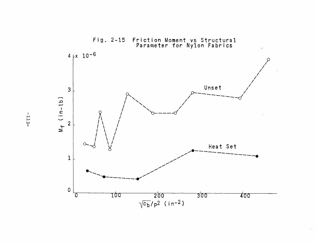
a.,"-"-"-•
"-,I
"-I
"-"-I
'?I
~+
JI
etSUJ
I0)
ILO
Ien
I::Jo-
II
+JL+
JI
+J ,
0.0
0)
roI
::JetSU
)I
0)
Ll1..C
I::I:
I+
J::>
II
encI
0I
(/)r-4~
I>~
•Z
"\
+J
"\\
,.......CL
"\
{'J(1
)09
\I
E't-
\C
0I
~L\
I\
~0)
aC+J
I\
aN
00)
P\
N0...
.-E
\~
+J
ro/
\
~OL
/\
.-etS
/
"LO-
/LL
/I
cf__I
LO--.....
I..........
r-4..........
II
.....--I
----N
.....::::0I
----~
----O
l--
()c-~_I
lI..C.D
----y/
IJ
a6
r-4Xa
~('f)
Na
(ql-u,)
J.~
-113-

the equilibrium configuration of the fibers, lowered theinternal pressure distribution, and resulted in fabrics withconsiderably reduced friction moments7
It is probable that a more rigorous mathematical treat-ment which includes the effects of stress relaxation andpartial slip propagation would be useful in obtaining a moreprecise prediction of the effects of fabric structure on thefriction moment. Nevertheless, it is felt that the analysisand experimental results presented here do indicate thegeneral trend of the important interrelations between fiberproperties, fabric geometry, and friction moment. In a latersection the question of partial slip propagation will be discussedin detail.
Parallel Yarn Rubbing in a Woven Fabric. The previous sectiondealt with the frictional moment that develops in a wovenfabric due to energy losses between the fibers. This type offrictional effect appears to be the most significant in mostmaterials at low curvature bends. However, experimentalinvestigations of a number of large scale fabric models haveshown that another mode of frictional behavior is possiblein some asymmetric fabrics. This mode of frictional effect,which does not appear to have been observed previously, involvesa rubbing together of two adjacent yarns as the fabric bends.When the rubbing is done against a frictional force, energy islost and a frictional moment will develop.
This yarn rubbing is illustrated in Fig. 2-16. There itcan be seen that as the fabric bends, the yarns will moverelative to the structure (as shown by the arrows) andconsequently relative to each other. If these yarns are incontact (as they are in some fabrics), energy will be lostto friction as the material bends. An illustration of
-114-

Centerline
'---' ~Motion
Ya rn~
'/ '
14~rn
Fig. 2-16 Yarn Motion DuringBending Fabric
Points
Fig. 2-17 Illustration of AdjacentYarn Rubbing-115-

adjacent yarns in contact is given in Fig. 2-1~.An approximate analysis will now be presented with the
aim of computing the frictional moment for this effect.Let:
u = relative motion between yarns and fabricmatrix at crossing point
~ = relative motion between adjacent yarns atcrossing point
~ = wave height of bent yarnscb = crimp of bent yarnsp = spacing of cross yarnsck = fabric curvaturem = number of bent yarns weaving togetherF = force between adjacent yarns at crossing
pointMf = frictional moment per yarn of fabricw = energy loss per length of fabric per yarn
.,......t.c = ;31iding coefficient of friction between ya:t'ns.If it is assumed that the shape of each yarn axis is
sinusoidal relative to the fabric centerline before and duringbending, it is possible to compute the relative motion betweenthe yarns and the body of the fabric, using the previouslyderived continuity equationo This relative motion can beshown to be zero at the top and bottom of each crown and amaximum at the crossing point between adjacent parallel yarns.At this point it has a magnitude equal to,
u =(;r)~ t.:b+~ + t~~2)Jk (2-77)
The relative motions between the yarns can be computedvectoria11y from this equation and the yarn geometry. It is
-116-

(2-78)
If a constant force acts between the adjacent yarns ateach crossing point, then the work done against friction caneasily be computed from the above equation. Assuming thatthere are m yarns weaving together, the frictional work perlength that must be done per yarn in order to achieve a givencurvature may be written as,
~F uRw = (2-79)m PcThe frictional moment can be found by combining equations
78 and 79 and differentiating with respect to curvature.Furthermore, it is possible to make a simplification byintrodu~ing the relation between crimp and wave height tospacing ratio as in equation 75. The frictional moment canthen be found in terms of the cross spacing, the crimp, thenumber of yarns weaving together and the frictional force.
(2-80)
(2-81)Fabrics in which adjacent yarns do not touch have a zero
value of F and, clearly, there is no frictional loss due tothis mechanism. However, in some fabrics this effect can beconsiderable. This is especially true in certain elastictype fabrics where stretch yarns are left in the material withhigh residual stresses. These stresses pull the cross yarnstogether and thereby develop a normal force F. In more
-117-

conventional fabrics that have internal yarn rubbing withoutresidual stresses,a normal force develops as the yarns compresseach other laterally. The magnitude of these forces dependson the amount of this compression and the lateral propertiesof the yarns.
Since the relative yarn motions that occur in this situa-tion are of considerable magnitude, large losses can be obtainedby this mode of frictional behavior. This may be desirablefor certain types of industrial applications such as dampingdevices or schrapnel protective materials.
Although the effect of internal yarn rubbing was developedin connection with fabric bending and recovery, it should bepointed out that this action may be important in internalfabric abrasion and fiber migration.
Structural Effect on Elastic Rigidity. The bending behaviorof woven fabrics was studied by both microscopic examinationand by means of large scale models. It was found that as thefabric bends there is a change of curvature produced in theyarns perpendicular to the axis of bending. However, thesections of these yarns that form the outer crowns of thebend are restricted from bending by the cross yarns and theyretain their original curvature 0 This is illustrated inFigs. 2-18 and 2-19~ This means that the lengths of yarn inthe unrestricted regions will have to undergo larger changesof curvature to conform to the curvature of the fab ric. Fromthis consideration the rigidity of a yarn in a fabric will begreater than that of the yarn before it was woven. On theother.hand, the yarn in a fabric follows a crimped path andthis would tend to reduce the rigidity of a yarn in a fabricover what it was originally. Both of these factors will beconsidered in the following analysis in an attempt to predict
-118-

Fig 2-18 CROSS SECTIONS OF FABRIC BENT TOVARIOUS CURVATURES
-119-

Fixed Curvature Region
Changing CurvatureRegion
Fig. 2-19 Effect of Fabric Structureon Rigidity
Fig. 2-20 Idealized Geometry ofWoven Fabric
-120-

f/Jo =
f/JB =S =rSt =
Pc =
M =
the elastic rigidity of a woven fabric.Let,
Ryf = rigidity of a yarn in a fabricR = rigidity of a yarn before weavingys = coordinate along yarn axis measured from
center of outside crowntangent angle of yarn axis--originaltangent angle of yarn axis--bentlength of restricted regiontotal yarn length between crownsspacing of cross threadsmoment per yarn applied to fabric
cb = crimp of bent yarns = St/L - 1q = Sr/StD = yarn diameterykf = fabric curvature8b = inclination angle of bent yarns.
If a pure moment is applied to the fabric, then it canbe shown that each element of yarn length not touching a crossyarn is also under a pure moment. These elements of yarn lengthwill then change their curvature (df/J/ds) by an amountM/R. On the other hand, each element of yarn in theyrestricted region will retain its original curvature.
Referring to Fig. 2-18 this can be expressed mathematicallyas,
d,~ b _--~:=ds
d 00 M--+-ds RY
(2-82)
Integrating this equation and assuring that f/J is continuous,
-121-

gives,
MrA +--!ro R
y
MSR---RY
(2-83)
This equation makes it possible to compute the fabriccurvature. If it is assumed that the yarn spacing remainsfixed, then the fabric curvature becomes,
,~ b (ST)
kf =Pc
With the aid of equation 83 this may be written as
(2-84)
M _ R = Pc Rykf - ~f ST - SR (2-85)
This result can be written in terms of the crimp and
(2-86)
(2-87)- 2 sin eb
2 sin
fractional length of the restricted region.R~ = --l~~_--Ry (1 + Cb)(l - q)
Equations 85 or 86 can be used directly, or else theycan be converted to a more useful form. This conversioncan be made in terms of the usual idealized model of a plainweave as shown on Fig. 2-20. From this model it is possibleto evaluate the quantities in equation 86. The result is,
PcR f D': cos eb-I!. • -.r.y ;;..-. _
Ry Pc9b cos 9b + D
y
Pc < 29b<j) sin e
b
The limits placed on the cross spacing result fromconsiderations of yarn jamming. Equation 87 is plotted on
-122-

Fig. 2-21. It illustrates the relation between fabric rigidityper yarn and looseness of the fabric. As tighter fabrics areconsidered (lower p ID ), the rigidity predicted will remainc yapproximately equal to the original yarn rigidity for a rangeof p ID and then the rigidity will increase sharply. Thisc yeffect was found by Chadwick25in his research on a varietyof fabrics. It was also found to be the case in experimentsconducted in this research. The cotton and nylon fabricseries described in Appendix E were evaluated on themoment-curvature instrument and the results of elastic rigidi~are plotted on Figs. 2-22, 23 and 24~ The measured relationbetween elastic rigidity and cross yarn spacing follows thetrend predicted by equation 87 for both series. The levelingoff of this relation at high spacings is more apparent in thenylon series since those fabrics cover a considerably widerrange of constructions.
The increase of elastic rigidity with decreasing spacingwas more pronounced in the unset than in the heat set nylonfabrics. This occurred because of the higher internalpressures present in the unset fabrics which apparently causeda reduction in the extent of slip propagation. Superimposedon this effect was the cross yarn restriction which occurredin both sets of fabrics. As a result both sets had higherelastic rigidities for the tighter constructions due to thegeometric effect considered in this section, and the unsetfabrics had additional increases in rigidity due to incompleteslip propagation. (The degree of slip propagation will bediscussed in a later section.) The measured results alsoindicate that the asymptotic complete freedom of motionrigidity is the same for both sets of nylon fabrics as expected.
An additional relation regarding the effect of geometric
-123-

ex:>
0L.ansl.L.
CQ)
W>a3=ns
LO\f-a~
~+
JC
l..q-""'"
-000-
0)
0:::
0+J(J)
ans
a,..-.f
wN
W,..-.f
N0
Ia
N('f')
•0
0)
a,..-.fl.L.
aa
LOa
LOa
••
Fl.
•N
,.......~r-f
a~
-124-

,ILO
<"''J0
I0
0z
IU
/<C
/0-
J(/)
/z
/~
/~
<C/
00
>-
/(J)
o/
>/
0
/>
-/
f-0
//
(Y)
0/0
0
Co'J/
>.
o//0
Cl
0::/
"'-.../
00
U./
a.
./f-
./-0
0./
(/)"..
CN
<CC1>
0...J
mW
(J)(J)
(J)OC
C1>C1>
.-0
Ns....-
s...s...
N..a
of-'C1>
C1>I
mO(/)
V)
Nl.L.C1>
r-fs...
m0
0C.-
UU
Cl
00
00
<.0of-'
LL
Iof-'
C-
OOs...
r-fUm
3=><
0
-..:t(Y
)N
0
(q1-ZUI)
~
-125-

ar-4•
0
t!)1
-Z
.0Z
ro(.)
lLU
)
~Q
.)
Iex>
0-
t:a
(I)0
1-
~•
r-'Q
.)I
z~
en0'::
zI
~I
>-II
0<.0
(/)
I~>
a
~
•>-
...-.-.I--
e;#-
00/1
~
<.!l/
Iu
/0•I
C-
o::/
~~
/a
(.)/0
•
I--./C
),/ef'
(/)0
----,.,-
c:(-0
-----------
-Jl-
I--W
WW
(I)U
)N
Z0
(Y)
:::>I--
N«
Iw
N<.0
:I:•
I0>
0,....-4
LLa
N0
co(0
N0
,....-4~
~.a,....-4
0::I
NC'-"
-126-
restrictions was observed for the cotton fabric series bentin the filling direction. In this experiment the cross yarnspacing of each sample was approximately constant, but thecrimp of the bent yarns varied cons iderab1y 0 The measuredvalues of elastic rigidity of these samples showed a definiteincrease with crimp. This is shown on Fig. 2-24 , togetherwith an extrapolation to the complete freedom of motion rigidityat zero crimp.
The measured effect of crimp on elastic rigidity is aspredicted by the theory. As originally stated, crimp tendsto reduce rigidity by providing excess yarn length for bending;and, it also tends to increase the rigidity by increasing therelative size of the regions of fixed curvature of the yarns.According to the results of the analysis which are shown onFig. 2-21 the latter effect of crimp predominates andrigidity increases with crimp at a fixed value of cross yarnspacing. (Note that the parameter used on this figure isthe yarn inclination angle) which is a measure of crimp.)This effect of crimp on rigidity is independent on the abilityof the fibers to slide by one another and is caused by ageometric interaction between the yarns in a fabric.
When structures, either of a non-plain weave, or else. 21,26plain weave with highly flattened yarns are cons1dered ,
then this analysis must be modified. This is due to the factthat in these cases geometric changes occurring in the crossyarns will not hold the bent yarn at a fixed curvature .. Therewill be a region of slightly changing curvature rather thanone of fixed curvature. This can be seen in some of theopen fabric sections on Fig. 3-11.
Relation Between Friction and Extent of Slip Propagation. Theprevious sections dealt with the relations between friction
-127-

<l'\C
\ctS
0
\u
\+
'en
0\
Q)
Q)
a\
L~
\L
\Q
)0
c..\
<J(J
)E
rn\
cC
L..\
o.-
u+
'~
\+
'~
coc
\0
aL..
<1\0
l.LctS>-
\en
\>
<l<\\>
.\
w+
'\
a'U
~..a
Ol
\u
\~
\0
\\~
+'
\a
en<1
ctS~
r-4W
\\~
\N
\N
Ia
N\
w\
Ol
I\
aLL
r-t\
xa
,...,LO
~..0
(Y')
Na
~'iNc"I""f
"""
_128_

moment, elastic rigidity, and fabric structure. It wasassumed t~at slip had propagated throughout the structure andthat the effect of friction was to provide a restraint againstslip rather than to prevent it from occurring. Under thisassumption, the elastic rigidity corresponds to the completefreedom of motion case corrected for geometric restrictions.
In this section, partial slip propagation will be consideredand it will be shown that the assumptions made previously holdonly for low levels of friction. It will be assumed that slippropagates lengthwise through each yarn element and that theextent of this propagation depends linearly on the frictionalinteraction. If the friction is low, the propagation iscomplete and if the friction is above a critical value, therewill be no slip at all.
In the case of bending under a pure moment, it was shownin Chapter I that slip propagated lengthwise through thestructure. The extent of the propagation was shown to dependon both the frictional interaction and the level of appliedload. Here, it is assumed that the extent of propagationdepends only on the frictional restraint and not on the load.The justification for this assumption is found in the factthat the internal fabric pressure changes as the material isbent. This means that while the slip is propagating into thestructure, the tendency for increased propagation due toincreased level of load will be offset by the increasedresistance to propagation caused by the pressure. In this waythe extent of propagation will be fixed even though theload increases.
The effect of the extent of slip on elastic rigidity canbe predicted by considering the yarns in the fabric to becomposed of sections of fibers having no freedom of motionand sections having complete freedom of motion against a
-129-

frictional restraint9 . The fractional length of each ofthese sections can be expressed in terms of the properties andgeometry of the fabric using the indicated assumption.
fL = L (1 - -)s g (2-88)
Where,Ls = length of yarn within propagation regionL = total length of yarn in one elementf = frictional force per length at one fiber
interfaceg = frictional force per length at one fiber
interface required to prevent all relativemotion
R = elastic rigidityWhen a fabric composed of a series arrangement of the twotypes of elements is subjected to a pure bending moment, thenet change of curvature can be found by computing the changein each section and then averaging. Assuming that the fibersare in an idealized square layered form, the section havingno freedom of motion will bend with a rigidity of Nf
2 Elfand the section having complete slip against friction will bendas the zero twist yarn previously analyzed (equations 1 and 50).Note that this involves the further assumption that thepressure distribution is constant in the latter region andthat the number of fibers is large. On this basis, themoment curvature relation can be shown to be,
2NEI. (1 - f) f ~f Nf gL/4
M = f ~ 11k + gf g 1 1 (2-89)(1 - g)(l - N) + N (1 - g)(l - N) + N
From this equation, the friction moment and the elasticrigidity can be related to the friction force and to eachother. This has been done for the case of fabric with a
-130-

large number of fibers in each yarn with the following results,Df Nfg L f f
M = -_. - (-) (1 - -) (2-90)f 4 g g
(2-92)
(2-91)1=RNEI.
l. 1 - f (1 1)g N
Df N# L ( NEI.\ / NEI.)M = - f 1 l.), \ __ l.f 4 \ R R
"-
These equations are plotted on Fig. 2-25 in dimensionlessterms. Note that the length term corresponds to twice thecross yarn spacing for the case of a plain weave fabric.
These equations show that the elastic rigidity increaseswith friction from the case of complete freedom of motion tothe case of no freedom of motion as the friction force variesfrom zero to g. If the value of fIg is small, the change ofelastic rigidity will be small for low values of friction forceand the result reduces to that found in the previous sectionswhere the elastic rigidity was assumed to be the sum of theindividual fiber rigidities independent of friction.
Equation 90 indicates the relationship between frictionmoment and interfiber friction force. This quantity variesapproximately parabolically with friction force. It firstincreases, goes through a maximum, and then falls to zero.The physical interpretation of this effect is that the frictionmoment increases with friction force until the reduction of sliplength becomes significant. Then, when the slip length approacheszero the friction moment falls to zero. For the case ofsmall values of fIg, the results of the analysis reduce tothose of the zero twist.yarn. In that analysis the effect ofpartial slip propagation was neglected.
The relation between friction moment and elastic rigidityis given by equation 92 and Fig. 2-25b. It is useful for the
-131-

.25
M .20fNf1JfL
.15
.10
.05
o 0.2 0.4
5.0
4.0
3.0
2.0
1.0
.25
.20
.15
.10
.05
oL..--_---L __ --L-_---.J __ -L- __ ..l.-_--L __ --'-- __
o 1.0 2.0 3.0 4.0 5.0 7.0R /(N f E I ~
Fig. 2-25 Relation Between Friction Moment,Elastic Rigidity, and FrictionForce
-132-

evaluation of fabriGs in which it is difficult to measure theinterfiber friction force. The functional relation exists forvalues of elastic rigidity between the limiting cases. Itincreases rapidly at first, goes through a maximum and thendrops to zero gradually.
Although equation 89 has been written for the bending ofa fabric, it can also be applied to other situations. In atwisted yarn, for example, the effect of changing the frictionforce will also effect the length of slip propagation and there-by cause changes in both the elastic rigidity and the frictionalmoment. In that case, the nature of the extent of propaga-tion will be more complex. Fibers will begin slipping on thesides of the bend and the slip will propagate towards theoutside and inside of the bend. Again, the elastic rigiditywill increase with friction from the case of complete freedomof motion to that of no freedom of motion and the frictionmoment will increase, go through a maximum, and then fall tozero.
An experiment was conducted to determine the effect offrictional changes on the elastic rigidity, the frictionmoment, and the bending recovery behavior. One cotton and onenylon fabric was used and treatments were applied to each forthe purpose of both increasing and decreasing the interfiber
t
friction. For each fabric seven samples were scoured andthen three samples were treated with softening agent (commer-cially available type) of varying concentration and threewere treated with a "frictionizerrr (MonsantoWs Syton) of,varying concentration. The seventh sample was used as acontrol. (See Appendix E for the sample descriptions.)
The bending parameters were measured on the moment-curvature instrument described in Chapter IV and the resultsare plotted on Figs. 2-26 to 2-29. For the nylon series,
-133-
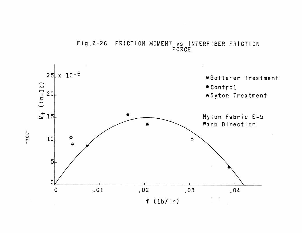
-f-JC(1)
E~
-f-JC
lOZ
ctSQ
)I
0Q
)E
LJ.JC
L.
~0
I--I--
ces0
'-.)(1)
of-JL
.L
.L
.0
~fr:
Q)
,........-..0
Q)
0l.L
C0
ctSL
.•
OJl.-
elL
.~
~-f.J
00
lJ.J'+-
C-f-J
Cm
00
~0
a.en
'-.)(/)
~L
.l.L
()•
()~ces
0':Z
==W.-Z
(Y)
-w0
0w
O':
>0
........lL
.C
.-Z"""""
lJ.j..0
~,.....
0~
~()
N'to-
Z0
a•
I-0•
~l.LtoN,...-4
I0
N•
0>
LLtoI
()()
a,...-4
xa
alO
alO
aN
,...-4,...-4
(Ql- u
I)J.~
-134-

+JeQ)
E+
J+
JC
euQ
)
Q)
EL
.+
JZ
....eu
0Q
)
L.
L.
~....
Q)
r--4....
0(.)
()C
0
"Q
)L
.e
0::::
"+
J+
J0
l.L.,
't-e
+J
,0
0~
~\
(/)u
(/)w
\()
•()
OJ
\LL
\~
\1)(Y
)w
~0
....\
z\
~\
e(J)
\"""-
>\
..a\
r--4>-
\......,
....~
't-0
N0t!l
~
•c..l
....(/)
<--JW
r--40
r-NI
NC.DI
Cl
0r--4LL
><~
aa
ar-f
-135-

both the elastic rigidity and the friction moment are plottedagainst the interfiber friction force. This quantity wasdetermined by means of the pullout test described inChapter IV. The bending parameters of the nylon series arealso given in crossplotted form. For the cotton series, itwas found unfeasible to measure the fiber pullout force andthe bending parameters are given only in cross plotted form.
The results of the nylon series show good qualitativeagreement with the theory. The elastic rigidity increasesmonotonically with interfiber friction while the frictionmoment increases and then falls. In order to compare thetheoretical relations with those measured, it was necessaryto graphically determine the parameter "g" from the frictionmoment plot. Then, the value of Df Nf L/4 was determinedfrom the fabric specifications and also from the maximum ofthe friction moment plot. The two values thus obtaineddiffered by a factor ot two, and the value obtained from thesecond method was used to plot the theoretical curve onFig. 2-26-.. On this basis, the a greement between theory andexperiment was good. The discrepancy between the two valuesof Df Nf L/4 obtained is probably due to the effect of avarying pressure distribution within the fabric which was notconsidered in this section.
The measured relation between elastic rigidity and frictionforce for the nylon series also showed good qualitative agree-ment with the proposed theory (Fig. 2-27,). The extrapolationof rigidity to a zero value of friction force on this plotrepresents the complete freedom of motion rigidity of thematerial and the value~' thus obtained was.~ within 5% of that ~determined from the tensile properties of the yarns. Thisvalue was used in conjunction with the previously determined
-136-

toIar-f
l{)
Cx
~I
0
r:tll.1J
a~
~+-'
VE-t
CJCJ
c::x:~
r:tlQ
)
>-0::
E-tL
LE-t
c::x:I--
ffir:tl
.nH
~co
0:z;
0C
lril
0:::z;
LLt
~0
(!J0
0r;:
ce-
el)0
0)
0L
a0::
()•()
r-'co
(Y')
~~u
Zl-
I-Z
(/)W
'"""<
~..0
-.J/
r-fW
0::/
w/()
UJ0-
/>
></
aN
w/N
c:t-
/Z
/.......,
/W
/:2:
~0::
0~/'
,/,/
z/
at-o
Ur-f
0::LL
<.Dex>
IN
aI
r-fN
•x
0)
0a
10
ato
0l.L
Nr-f
1'"""4~.c1'"""4
....I
~C'-'
-137-

COTTON FABRIC T-3
5 x 10⁻⁶ e
4 e
Mf(in-1b) 3 •
2 F We e Syton Treatment
1 • • Control~ ~ Softener Treatment
o 3R (in2
Fig.2-29 FRICTION MOMENT vs ELASTiCRIGIDITY
o
-138-

value.of "g" to establish the theoretical relation for thismeasurement. The comparison between theory and experimentis quite good for moderate :values of friction. " At the higherlevels the predicted elastic rigidity is considerably higherthan that measured. This discrepancy is probably due to theeffect of yarn flattening which was not included in thisanalysis and which has the effect of changing the ratio ofthe complete freedom of motion rigidity to the no freedomof motion rigidity. This ratio was taken to be llNf inequation 91.
The relation between friction moment and elastic rigidityis plotted on Fig. 2-28 for the nylon series. The measuredvalues on this graph have been corrected from the originalones by adjusting each point to the value lying on the bestsmooth curve through the original data. Then the theoreticalrelation was plotted based on the parameters used previously.The agreement between theory and experiment is excellent forthe lower values of elastic rigidity, then at the higher valuesthe agreement becomes poor because of the previously discusseddiscrepancy between theoretical and measured elastic rigidityat high friction levels. Note that the samples treated withthe friction reducing treatments fall in the initial regionof the curve and they are followed by the control sample andthe samples treated with the frictionizer.
The measured results of the cotton series are shown.onFig. 2-29. The qualitative relation between the variablesis as expected although it appears that the levels of inter-fiber friction force was insufficient to extend the measuredvalues beyond the point of maximum friction moment. As inthe case of the nylon serie~, the data points are identifiedby the type of friction treatment applied. Again, the lowfriction fabrics lie in the initial region of the curve whilethose with high friction lie"at the end.
-139-

CHAPTER IIIBENDING RECOVERY OF TEXTILE STRUCTURES
Since the bending recovery behavior of fabrics plays anextremely important role in the performance of textile materialsfor clothing purposes, a great deal of research has been donein this area28,~9 It has been shown that the individual fiberproperties determine recovery behavior to a great extent andthat fibers with good recovery from tensile strains generallyhave good recovery from bendin~~ A number of investigations
14,15,31have demonstrated however tHat the bending recovery alsodepends on the frictional interactions of the fibers. Althoughthis effect is generally of secondary importance, it certainlywarrants careful investigation because of the great importanceof bending recovery in user acceptance of new materials andfinishes.
In the first section of this chapter a bending recoveryrelation will be established which can be used to characterizethe performance of any material or structure. This relationinvolves the use of dimensionless variables and permits theevaluation of materials independent of their size.
In the sections to follow, the recovery behavior will begiven for the limiting cases of fiber motion. Then, followingthe procedure of Chapter I, the intermediate cases of fibermotion will be considered. It will be shown that frictionnot only produces an intermediate behavior, but also introducesan entirely different type of behavior in certain cases.
-140-

REPRESENTATION OF BENDING RECOVERY
Bending recovery is defined as the fractional amount ofcurvature recovered to that imposed on a specimen. In standard
32tests the imposed curvature is usually determined by thecurvature a fabric experiences when it is bent around a slabapproximately 10 mils thick. Since the thickness of fabricsvaries, the imposed curvature of such a test will varyfor different materials. Also, the severity of a given imposedcurvature will depend on the thickness of the fabric. Forthese reasons a standard test which involves bending a materialaround a slab of fixed thickness is not always satisfactory.This was demonstrated by Bostwick in an investigation of a
33number of test procedures A better measure of bendingrecovery is to bend a fabric to a radius of curvature that isa fixed fraction of the fabric thickness. The magnitude ofthe imposed curvature in this case can be expressed indimensionless form by multiplying it by the half thickness ofthe material as is done in Chapter I. The physical significanceof this dimensionless curvature is that it is the same as themaximum strain that would exist in a solid material of equalthickness bent to the same curvature. For example, thedimensionless curvature of a fabric bent around a thicknessequal to itself is one-half.
For a complete representation of bending recovery, therecovery at every possible value of imposed curvature mustbe known. This functional relation has been used in a number
14 15of previous investigations 'and will be used here andreferred to as the recovery curve. Both variables on thiscurve range from zero to one; and, on this representation itis possible to plot the recovery of anyone or two dimensionalstructures such as fibers, wires, ropes, films, fabrics, andother materials.
-141-
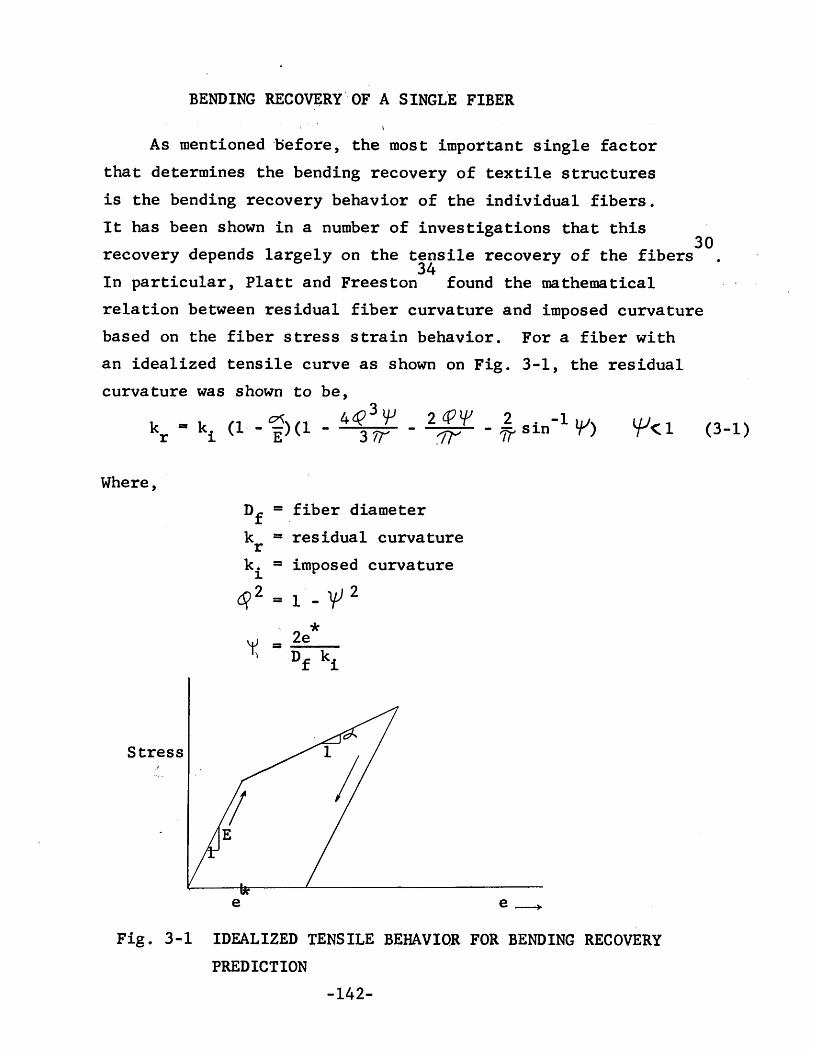
BENDING RECOVERY'.OF A SINGL'E FIBER
(3-1)lfl<l2c{Jl{J 2 -1)1.1:rr - 11' sin T ).I
As mentioned uefore, the most important single factorthat determines the bending recovery of textile structuresis the bending recovery behavior of the individual fibers.It has been shown in a number of investigations that this
30recovery depends largely on the tensile recovery of the fibers34In particular, Platt and Freeston found the mathematical
relation between residual fiber curvature and imposed curvaturebased on the fiber stress strain behavior. For a fiber with
3-1, the residualan idealized tensile curve as shown on Fig.curvature was shown to be,
_ ~ 4t{J3lfkr - ki (1 - E)(1 - 311
Where,Df = fiber diameterk = residual curvaturerk. = imposed curvature1
~2 = 1 - vJ 2
'K2e*
= Df ki
Stress
e e~
Fig. 3-1 IDEALIZED TENSILE BEHAVIOR FOR BENDING RECOVERYPREDICTION
-142-

t =2D fN?f fY~ y
Where,tf = fabric thicknessNf = number of fibers in yarnr = height to width ratio of yarn section
2Y = yarn packing factory
k* = dimensionless curvature of fabriciB = bending recovery
From the definition of dimensionless curvature,
ki* = ki Df --Ii:
(3-2)
(3-3)
This equation can be used in conjunction with equation 1
which defines the recovery of individual fibers. For fiberswhich do not follow the assumptions on which equation 1 isbased, it is possible to use any other formulation whichdescribes the recovery of individual fibers. For example,
· lIb d h. · 35 · h.exper1menta resu ts can e use at t 1S p01nt . to g1ve t 1Sinformation 0 If, however, equation 1 is assumed to hold,then the result for the recovery behavior of a fabric withcomplete freedom of fiber motion can be obtained byrewriting the equation in terms of bending recovery andsubstituting equation 3.
B =
-144-
(3-4)

The recovery behavior predicted by equation I has beenmeasured by Platt and Freeston for a number of metallic fibersand for viscose rayon with good agreement between theory andexperiment.
In the following sections this formulation will be usedto predict the recovery of fiber assemblies. Then frictionaleffects will be included to determine how this factor affectsrecovery. It should be noted that the residual curvaturepredicted by equation 1 applies to fibers whose stress-strainand recovery behavior can be characterized by the idealizationof Fig. 3-1. For other materials, the individual fiberrecovery must either be recomputed or measured directly.
LIMITING CASES OF FRICTIONAL INTERACTIONJust as in the case of the bending of textile structures,
it is possible to estimate the recovery from bending by consider-ing the limiting cases of frictional interaction. This canbe done for the case of a woven fabric bent by assuming thatthe change of curvature of the centerline of the fabric isthe same as that of the individual fibers. This assumptioncan be applied most satisfactorily for yarns with moderatecrimp and for moderate imposed curvatures.
For the case of complete freedom of motion, the fiberswill bend independently and on the basis of the statedassumption)equation I can be applied directly. However, toexpress the result in terms of the dimensionless curvatureimposed on fabric, it is necessary to express the fabricthickness in terms of the fiber diameter. This can be donefor a yarn of elliptical cross section in a fabric with athickness of two yarns. The result is,
-143-

p
*k.1.
~2=l_r2
p = 2 e*f:y
r(Complete Freedom of Motion) (3-5)
*p = 2 e
For the case of no freedom of fiber motion, the fiberswill not slip and the fabric will be assumed to be made ofyarns which behave as monofilaments. In that case, thediameter term of equation 1 must be replaced by the yarndiameter. The resulting recovery equation is the same asequation 4, but the parameter "p" is replaced by,
(no freedom of motion) (3-6)This means that the recovery behavior for the case of
complete and no freedom of motion follow the same form buthave different values of a parameter which is a measure of thenon-recoverability of the fibers. This recovery relation isplotted for several values of this parameter on Fig. 3-2.These curves are given for ~/E = 0, and can easily beadjusted for non-zero values of this variable by realizingthat its effect is to shift the curve upwards to completerecovery by a fractional amount equal to its magnitude.
The results given here for the limiting cases of freedomof motion can directly be applied to situations in which thefibers form clusters in the yarn. In that case it is merelynecessary to modify the values of the parameter in terms ofthe number of fibers in a cluster.
The recovery behavior predicted by this analysis isgenerally observed for textile materials where the effects of
34sliding against frictional forces can be ignored Note
-145- .

~al..L.
lOW
•0:::
a::JI-<t:::::>~:::>0
I-a
~0
•U
)W
IIa
U)
l..L.L.J.J
l..L.W
-.JW
"""-Z
1)
a0
U)
I-Z
U)
(Y")
W<t:
•~
-Ja
w0
I
*0
(J)
~>
I-U)
•>-
«N
~--I
•W
a..a
::::>a0w
•n
:(!)
MZ
•a
0:2:
Wm•
NII
I(Y
)a..
•0)
alO
al..L.
••
Ma
m
-146-

that the recovery is not strongly affected by the magnitudeof imposed curvature for values of dimensionless curvatureapproximately equal to 0.5. Since the standard bending testgenerally operates at this level, the results can be used forconstant thickness slabs even though the imposed curvaturemay be different for samples of different thicknesses.
EFFECT OF FRICTION ON RECOVERYIn Chapters I and II it has been shown that the effect
of friction on bending of textiles or multi-layer beams iseither to impose restraints on relative fiber motion or elseto prevent the complete propagation of slip. Both of theseeffects will affect the bending recovery.
In the first case, recovery will be affected since thefibers will not reslip to the same extent that they did duringbending. This type of non-recoverability due to friction wasdiscussed analytically and experimentally in Chapter I formulti-layer beams and analytically in Chapter II for the one-dimensional case of slip and strain. Since this type of non-recoverability arises from a structural effect rather thanfrom permanent fiber deformation, it will be referred to asthe "friction-elastic" type of non-recoverability.
In the second effect, friction will prevent relative fibermotion in parts of the structure and cause larger strains todevelop. This will clearly reduce the recovery.
Friction-Elastic Effect. In Chapter I, an analysis was presentedto determine the recoverability of a multi-layer beam underconstant pressure that is bent to a fixed curvature. Theresidual curvature due to the balance between the elasticand frictional forces in the system are given by equation 80.When this result is applied to a textile structure and
-147-

rewritten in terms of bending recovery, the result is,
B =
F1",,-'*ko
~
*2F<ke1.
(3-7)
Where,B = bending recoveryMf = friction momentR = elastic rigiditytf = fabric thickness.
This equation relates bending recovery to imposed curvaturefor various values of a dimensionless parameter which expressesthe friction relative to the elasticity of the system. Bendingrecovery for this effect is plotted on Fig. 3-3. It isinteresting to note the difference between the recovery result-ing from this effect to that from purely plastic deformationshown on Fig. 3-2? In this case the recovery increases withimposed curvature while in the other it decreases with curvature.
Effect of Frictionally Induced Strains on Recovery (P1astic-Elastic Effect) 0 When frictional forces prevent completeslip propagation the effect on recovery can be estimated byassuming that part of the structure bends with no freedom ofmotion and part with complete against a frictional restraint.This is the same assumption made and discussed in the caseof frictional effects in bending in Chapter II. Again, thelength of propagation of slip will be assumed to dependlinearly on the frictional force as given by equation 88. If
-148-

10
0•
WI--
aU
)(.)
0w
a..LL
~lLLJJ
(I)(.)
0llI::I-(I)
•W
I--0
-1(I)
Z<C
0....Jw
U)
I:z
zlJ.J
a~
(Y)
I--0
c..J0
(f)~
>lL
*>-
~0:=:
Ck:W
0N
>lL
•0
0c..J
Wl.JJ
0::0.-:
::>I--c..!J
<CZ
>0::C
l::>
~z
0•
w0
m(Y')I
(Y')
II
0)
0lL
0LO
0•
•r-f
0
-149-

each element of yarn changes its curvature by the same amountand this change is equal to the curvature of the fabric center-line, the frictional effect can be determined from the recoveryequations for complete and no freedom of motion given byequations 4, 5, and 6~ The length of yarn through whichslip has propagated will have the residual curvature corres-ponding to the complete freedom of motion case and theremainder will have a residual curvature ,~correspondingto no freedom of motion. The fractional amount of each caseis given by equation 88. This permits calculation of theaverage residual curvature of the fabric and this can be usedto determine the bending recovery in terms of the limitingvalues.
f fB = (1 - g) BCFM + (g) BNFM (3-9)
The result indicates that on the basis of the statedassumptions, the recovery for this effect of friction will bethe weighted average of the recovery curves for the limitingcases of freedom of motion. The weighting factor isdependent on the friction of the system as indicated.
It is interesting to note that the two frictionaleffects on recovery discussed in this section are quite differentin the way they act. The first produces a non-recoverabilityby not allowing the fibers to return to their original relativepositions. The fibers need not be permanently deformed forthis mechanism to act. The non-recoverability is purelystructural and arises from a balance of the friction forceswith the elastic restoring forces. A good example of thistype of deformation is found in fiberglass fabrics. In thistype of material the recovery is often extremely poor, eventhough the fibers are not at all permanently. deformed. This
-150-

is especially pronounced at low curvature bends when therecovery predicted by this effect is lowest.
The second effect of friction is not purely structural.It acts to reduce recovery by increasing the effect of thepermanent fiber deformations by preventing relative fibermotion in parts of the fabric. In this way the recovery goesfrom the complete freedom of motion case to that of no freedomof motion as friction increases. This effect is greatest inlarge curvature bends.
Combined Effect of Friction and Permanent Fiber Deformation.The results of the previous sections can be utilized to obtaina prediction for the combined effects of friction and permanentfiber deformation on bending recovery. This combined effectwill give the recovery behavior for the levels of frictionalinteraction between the limiting cases.
When a material is bent to a certain level of curvatureand released, it will maintain some amount of residual curva-ture. This residual curvature was shown to arise from twodifferent effects; permanent fiber deformations, and frictionallyheld deformations. In the first of these effects, referredto as the plastic-elastic case, it has been shown that theresidual curvature varies with the imposed curvature in amanner that depends on the fiber properties, the structuralgeometry, and the interfiber frictional interaction 0 Thefrictional interaction in this case determines the level ofresidual curvature relative to the limiting cases of freedomof fiber motion as illustrated on Fig. 3-4. Here, it can beseen that the residual curvature due to this effect is smallfor low imposed curvature and increases to considerablelevels at high imposed curvatures.
-151-

The second effect which produces a residual curvatureresults from frictionally held deformation. This friction-elastic effect arises from an inability of the fibers toreverse the relative motions which they experienced duringbending. The relation between residual and imposed curvaturefor this effect was computed in Chapter I and is plotted onFig. 3-4. On this graph it can be seen that this residualcurvature is approximately constant for all levels of imposedcurvature.
A comparison of the residual curvature relations resultingfrom the two effects shows that the friction-elastic effectpredominates at low curvatures, while the plastic-elasticeffect predominates at high curvatures. This means that theway in which interfiber friction affects bending recoverydepends on the level of imposed curvature. For low curvatures,friction is important since it prevents fibers from retracingthe motions which they experienced during bending. Then, athigh curvatures, friction prevents the complete propagation ofslip during bending and thereby increases the level of fiberstrain and of the corresponding permanent deformation.
In order to evaluate quantitatively the combined effectsof the two types of residual curvature, it will be assumedthat the net residual curvature equals the sum of the residualcurvatures due to fiber deformation and frictionally helddeformation 0 This is shown on Fig~ 3-4. The justificationfor this assumption is obtained from a consideration of theequilibrium configuration of the fibers. For fibers that donot undergo permanent deformations, the residual curvaturecorresponds to that of the friction-elastic case. This residualcurvature represents a point of balance between the frictionalforces, which tend to hold the material bent, and the elastic
-152-

restoring forces, which tend to return the material to theoriginal equilibrium configuration. When the fibers do under-go permanent deformations, the elastic restoring forces willtend to return the material to the state that corresponds tothe altered fiber equilibrium configurations. Since theresidual curvature due to the friction-elastic effect acts toproduce a fixed change in curvature from whatever equilibriumconfiguration exists, the assumption made appears reasonablyjustified. There is one difficulty however that does arisewhen making this assumption. The recovery behavior of theindividual fibers, and therefore the plastic-elastic para-meters, depends to some extent on the state of fiber strainl5
When this effect is significant, a coupling term must beintroduced between the residual curvatures and the simplesuperposition assumption will not hold. This effect wasneglected for the purposes of this investigation.
= dimensionless imposed curvature= dimensionless residual curvature
Let:*k r
*k i
F
G
f
g
= friction force per length between fibers= friction force per length between fibers required
for prevention of all slipsubscripts:
p refers to plastic-elastic effect,f refers to friction-elastic effectnfm refers to no freedom of motioncfm refers to complete freedom of motion.
-153-

*k .-1.
Fig. 3-4 RESIDUAL vs IMPOSED CURVATURE FOR COMBINED PLASTIC-ELASTIC"AND FRICTION-ELASTIC EFFECTS
-154-

The residual curvature due to the plastic-elastic effectdepends on the amount of interfiber friction and the recoveryof the limiting cases as in equation 9.
k* = f k* + (1 _ f) k*r,p g r,nfm g r,cfm (3-10)The residual curvature due to the friction-elastic effect
can be obtained from equation 7. It can be ~ewritten in termsof the relative amount of friction by applying the results ~fequations
G (f Ig) (1 - fIg) 2
From the indicated assumption,
(3-11)k*i» 2(f/g)(l-f/g)2G
(3-13)
k* = k* + k* (3-12)r r,p r,fThese equations can be combined and written in terms ofbending recovery rather than residual curvature,
*B = f B + (1 _ !) B _ k ..r•f
g Nfm g cfm *k .1.
The individual terms of this equation can be evaluated fromequations 4, 5, 6, and 11. Then, the bending recovery can beseen to depend. on five parameters,
B = B(P f Nf, ~/E, G, fIg) (3-14)c m,This bending recovery relation has been plotted on
Figs. 3-5 and 6 for several values of the parameters. Themost striking result that can be seen is the reduction ofrecovery at low levels of imposed curvature and a recoverycurve that goes through a maximum. This type of behavior has
-155-

been previously observed by Daniels15and was also observed inthis investigation. Note that the recovery curves for thecombined effects reflect a combination of the recovery curvesfor the plastic-elastic and friction-elastic effects shownon Figs. 3-2 and 3.
On Fig. 3-5 the recovery relation is plotted forP f = 0.1, 0/E = 0, and for the case of complete slipc mpropagation (fig = 1). The amount of friction acting in thesystem is given by the dimensionless parameter F. As thisvalue increases, the recovery gets progressively worse at thelower levels of imposed curvature .. At the higher levels, theeffect of friction is less and the recovery curves areasymptotic to the zero friction case. This occurs becausethese recovery curves are restricted to the case of completeslip propagation.
On Fig. 3-6 the recovery curves are shown for a materialin which the effect of propagation of slip is included. Thecurves are plotted for Pcfm = 0.1, Nf = 100, ~/E = 0.5,G = 0.1, and for various values of fIg. The limiting cases ofrecovery occur at fIg equal to 0 and 1. For the intermediatecases the friction-elastic effect increases and then decreaseswith fIg, while the plastic-elastic effect continuously shiftsthe recovery curve closer to the no freedom of motion limit.
The important conclusion to be drawn here is that therecovery behavior for the intermediate cases of friction differsqualitatively from that found for the limiting cases. Thiswas also shown to be the case for the bending behavior asdescribed by the moment-curvature relation. For the highimposed curvatures, friction acts to give a recovery which isbetween that of the limiting cases. At these curvatures, therecovery performance relates to the ability of a fabric torecover from imposed wrinkles or creases. At low curvatures,
-156-

0LO
W(/)0
a0..
~~
•0
a(/)
IIII
(/)W
~W
0-
................J
'6a
za(/)zw~0
LJJ0:=
aen
=>>
~*
«>-
:>~
0:=~
W::>
:>u
Na(.)
aw~(!l
Zr-f
r-f0
a•
z•
awm
0
LOII
I(Y
)
C)
l.L.a
LOa
••
r--4a
-157-

,-4
0In
,.......0
••
~O
r-f0
0•
IIII
IIII
't-W
(!Ja..Z
--.........(5
(Y)•
*.:Yo
0lLJU
)0a..~U
)(/)
W--Jz0U
)Z
lJ.JW
~~
::>.....C
l<:>
U)
~>
=>U>-~w:>0uW0::
(!)ZC
lZWO
J
(!)I(Y
)•0>
lL..
aII
••
•-158-
••
a
•
N••
a

friction reduces the recovery below that of both limitingcases. At these curvatures the recovery gives only a smallindication of how a fabric will recover from imposed wrinkles,but it does give a strong indication of the "hand" of thematerial. Fabrics with low recovery from low curvature bendsdiffer noticeably in their aesthetic appeal from fabrics withhigh recovery.
A number of experiments were conducted to establish thevalidity of the proposed theory of frictional effect onbending recovery. The procedure used is described in ChapterIV. To illustrate the qualitative nature of the frictionaleffect, a cotton canvas fabric having a rather strong inter-fiber frictional interaction was first evaluated. The resultsof this experiment are plotted on Fig. 3-7. The recovery ofthis material very definitely follows the predicted trendand has very poor recovery at low imposed curvatures followedby a maximum in the curve and then a gradual decrease.
Two additional series of experiments were conducted todetermine the effect of friction on the recovery behavior ofa nylon and a cotton fabric. These samples were treated withvarying concentrations of a softening agent and with varyingconcentrations of a frictionizer. The detailed sampledescriptions are given in Appendix E and the results of therecovery measurements are given on Figse 3-8 to 3-10, and onTable I in Appendix F.
The recovery of the nylon samples shown on Fig. 3-8represents the results of a treatment with a softening agent,a frictionizer, and a control sample. The amount of frictionalinteraction of each of these samples is specified in terms ofthe fiber pull-out force, which was measured by the proceduredescribed in Chapter IV. A similar plot for three of thecotton samples is given on Fig. 3-9. In this case the amount
-159-

0uJ
IC
J)
0a
,0
-L
~
I.n
<.DctS
•I
l.L.U
)
IC
/)
I(J)
LLJ
Ico
--.J>
l()
2I
ca
Ico
LrJ,
UU
)0
::Z
=:JI
CLJJ
l-I
0~
~<t
I+
J•
:>
I+
"0
~0
:::>I
0(/)
0I
>I
(Y)
/•
>-I
~
•w
/:>
/a
/N
0/
•W
/0=:
"(!J
/Z
/I
0('.
zw'"
m........--"'--e--
-----.-...---
f-
aco
CD~
Na
I•
••
••
(Y)
r-4•
rnlL.
CD
-160-

*
a
c.o
a~~
'"-rI
~I
I"
II
I",~
,I
,~~
II
I~~
,I
I~
~I'61
I~~
I1:J,
JB
~I
3.t&
~l<t
JI
IJ
J
IJI
IJ
Jf
JJ
II
JI
JI
II
II
IJ
II
JI
J41<If
II
II
I'//I
//
'<t;e/
,II
III
\I(
a()""
.~~-~.L
~JI!4)"'J.......~
0"'---'l.
------~tr-=tJ=.()--=:=.....
a-<t_____
N
~
..;t......ooco
Cl
ZWQ)
(/)(IlW...JZocoI(Y
)
Ol
(/)Z
WW
0::~=>-
t-O
«:>(/)0::>
:::>U
oLJJ(/)o0-
:;E>-0::W:>ouW0::
m-161-

o
••• •*N
••
•
•f
II
II~
II
~I
I~
II
t~,
~1-4
Ig
~I
I~
isI
I00
II
II
II
ttII
II
II
IJ
II
II
II
II
iJ/I
/I
/I
II
•t)
I/
\I
,.•ex:>
•o
(J
~I
~I
~I
~I
~I
~I
~I
CI)IIII()IIIIIIIIII(J
IIIII~()'<t
_-L
-_
_-L-_-=-......
~-~~~__
...........--..-....J0
o
•
U)
U)
LJJ-...JZoU
)z
WLLJ
~~:J.....o
ex:>(/J~>
:JU
owU)
o0-
~0'>I(Y
")
ozwm >-~w::-oc...JW~
m
-162-

Fig.3-10 BENDING RECOVERY vs ELASTICRIGIDITY
• 9
. 8
,.7 *k.I.6 .148
B .262. 5
.620.4
1.00.3
.2
.1
Warp DirectionCotton Fabric T-3
~ Softener Treatment
• Control
o oR
e Syton Treatment
5
- Ib)
-163-

of interfiber friction is given in terms of the elasticrigidity of the sample. This quantity was shown to be amonotonically increasing function of friction in Chapter II.
The results show that friction affects the shape of therecovery curve as predicted. At both the low and high imposedcurvatures the samples with the higher friction levels showedpoorer recovery. In the low curvature region this was due toincreased resistance to relative fiber motion, and in thehigh curvature region it results from a reduction in theextent of slip propagation 0
For an additional representation of the recovery results,the bending recovery is plotted as a function of friction,measured in terms of elastic rigidity, for various levels ofimposed curvature on Fig. 3-10. This curve illustrates thestrong effect that friction has on bending. By changing thefrictional interaction between the fibers it was possible toobtain changes in recovery amo~nting to almost a factor oftwo.
EVALUATION OF CROSS-SECTIONS OF BENT FABRICSIn order to obtain a better understanding of the structural
geometry that develops during fabric bending, a number offabric samples were bent, embedded, cross-sectioned, andexamined microscopically. The technique employed is describedin detail in Chapter IV. Several of these samples werephotographed and are shown in Figs. 2-18., 3-11, and 3-12.These photographs include three series of samples which illus-trate the effects of frictional changes, structural changes,and curvature changes. The following observations can bemade from these cross-sections:
1 .. There are two fundamental modes in which a fabric
-164-

can bend at high curvatures36 The first is a "square" modeand it is characterized by a yarn path which is asymmetricto the plane of bending. Cross-sections taken of adjacentyarns in this mode are mirror images of each other. Thesecond mode is a "round" mode and it is characterized by asymmetrical yarn path. In this case, sections taken atadjacent yarns are different since the bent yarns willalternatingly pass over and under the cross yarn at the centerof the bend. Both of these modes occur in each of the fabricseries photographed. Because of the similarity of adjacentyarn sections in .the square mode, only one cross-section isrequired to describe this geometry, whereas two are requiredfor the round mode. It is interesting to note that thefrequency of occurrence of the square mode is considerablygreater than that of the round mode. This was not only found.tobe the case in the sections shown, but also in a number ofadditional samples which were sectioned.
2. During bending the yarns experience only smallcurvature changes in the regions where they form outsidecrowns. This observation corresponds to the assumption madein the analysis for predicting the effect of cross yarnrestriction on elastic rigidity. This effect is most pronouncedin fabrics having round cross yarns, since only a small amountof yarn compaction takes place in these materials.
3. In order to satisfy the continuity requirementsof bending, the fibers at the inside crowns buckle towardsthe inside of the bend. The extent of this buckling is smallbut it can be seen by careful examination of the cross~sections on Fig. 3-11. Another form of buckling can alsobe seen in the loosely woven fabrics in this figure. Thisbuckling involves a lateral movement of the yarns out oftheir original plane.
-165-

a b c
d e
Fig 3-11a CROSS SECTIONS OF BENT FABRICS(NYLON SERIES N)
-166-

f g h
j
Fig 3-11b CROSS SECTIONS OF BENT FABRICS(NYLON SERIES N)
-167-

4. Perhaps the most pronounced effect that can beobserved from the fabric cross-sections is the compaction ofthe cross yarns. The effect of this compaction is to changethe original cross-sectional shape of these yarns to a circularform. This effect is, of course, less noticeable when thecross yarns are originally round. Since the extent ofcompaction can be considerable in some fabrics, it appearsthat this factor may have some influence on their bendingrecovery. If the yarns are able to recover elastically totheir original cross-sectional shape, they will assist inreturning the bent yarns to their original configuration.This suggests that it would be advantageous to design yarnswhich compact readily during bending and then rapidly springback to their original shape during recovery.
5. The fabric series shown on Fig. 3-12 is composedof seven samples each having a different interfiber frictionalinteraction, but an identical geometric structure. Thesesamples were prepared by treating a nylon fabric with variousconcentrations of both softening agent and frictionizer(Syton). The bending and recovery behavior of these samples,reported previously, demonstrates that friction played asignificant role in establishing the fabric properties.However, the cross-sections on Fig. 3-12 show that there is noapparent difference between the bent geometries of thesamples. This indicates that alth.ough friction may effectthe extent of slip propagation and the~resistance againstrelative fiber motion, it does not significantly affect thegeometry of bending at high levels of curvature.
-168-

a
b
c
d
e
f
9
h
Fig 3-12 CROSS SECTIONS OF BENT FABRiCWITH VARYING FRICTION TREATMENTS
-169-

CHAPTER IV. EXPERIMENTAL. TECHNIQUES
INSTRUMENT FOR MEASURING MOMENT-CURVATURE RELATIONThe fundamental characterization of the bending behavior of
a material is given by the moment-curvature relation .. This curvecan be used to determine such quantities as stiffness, non-linearity of bending, energy loss in bending,and non-recoverabilityin bending. An instrument for making this measurement was designedand constructed. This instrument imposes a constantly increasingor decreasing curvature while measuring bending moment continuously.
In an ideal, linearly elastic material there is no need forany elaborate equipment for measuring the moment-curvaturerelation. In that case this relation will be linear and can bedescribed by only one number. There will be no rate dependenceand the behavior will be independent on the direction of loading.Because of this, very simple evaluation techniques can be used tomeasure the bending behavior of ideal materials. For relativelyrigid materials a beam or strip can be loaded as a simply supportedbeam or a cantilever and the loads required to produce a certaindeflection can be used to compute bending rigidity. This type oftest37 is used for many applications, such as the evaluation ofreinforced plastics and stiff fabrics.
For relatively flexible materials that can be considered asideal, it is possible to measure the rigidity by a number ofgravity loading techniqu~s. A sample is placed in a configurationin which gravity forces will cause deflections. The extent ofdeflection or the amount of material length necessary to producea certain deflection can then be used to determine the rigidityrelative to the weight per length of the test stripe The mostcommonly used of these techniques for textiles are the cantileverand heart100p tests38. In both of these tests the relationbetween gravity deflected geometry and rigidity has been deter-mined by rather sophisticated mathematical techniques. However,
-170-

since the assumption of ideal bending behavior was made in themathematics, the rigidity calculations are not valid for non-ideal materials. This means that accurate quantitative measure-ments of many textile materials are not possible by these methods.And, it has been shown that sometimes even qualitative measurementsare not possible. This was shown by Shwartz39 in an experiment inwhich fabrics were evaluated by a number of techniques and therelative rankings of rigidity were not found to be fully consistent.
Because of the general non-ideal bending behavior of textilematerials, it is not always possible to use an experimentaltechnique which can only properly be used for ideal materials.To do so would be equivalent to measuring tensile modulus of amaterial by merely applying a constant weight and measuringdeflection. This may be satisfactory fo~ certain cases, but it isnot so for research investigations in which fundamental mechanismsof deformation are under consideration.
A number of attempts have been made in the past to measurethe complete moment-curvature relation rather than just measure asingle number to describe bending. Eeg-OlofssoJ2,~lIsShi 11, andLivesey and Owens 7 have constructed instruments for this purpose.Although each of these instruments operates on a different principle,the general procedure involves subjecting a fabric or yarn sampleto progressively increasing curvatures and then measuring theapplied bending moment.
In Eeg-Olofsson's instrument the curvature is imposed by therotation of one end of the sample while the other end is fixed.A clamp connected to the rotating end floats on a pool of mercuryso that the ends of the sample can c9me together during bending.The bending moment is measured from the current flow in a coilwhich transmits to;que to the rotating end. This method seems tohave been used with reasonable success. However, there appear tobe several difficulties in sample mounting and maintenance ofthe pool of mercury.
Isshi's device imposes a progressively increasing curvatureto the sample by moving and rotating one end of the sample in a
~171-

prescribed manner. This involves a complicated arrangement ofgears, cams, slots and sliders. The other end of the sample isfixed to a shaft which is mounted on jewel bearings and whichis prevented from rotating by a torsion spring. As the sampleis bent, the fixed end will cause a slight rotation of thetorsion spring. This rotation is reversed by another spring untilthe original rotation is nullified. The deflection of the secondspring for nulling can be related directly to the bending momenton the sample. The major disadvantage of this method is that thetest is performed in a series of steps and during each such step
I
the load is changed slightly by the measurement procedure.The method of Livesey and Owens is an approximation to a pure
moment-curvature measurement. A sample is mounted on a clampwhich can be rotated about a horizontal axis. A small tab with aprotruding pointer is connected to the free end of the sample.The gravity acting on the pointer will produce a moment an~ a forceon the sample. But, according to Owens, the force will benegligible under certain conditions. The curvature can beincreased by rotating the clamped end of the sample and the bend-ing moment can be obtained by measuring the angle of the pointer.The difficulty with this procedure lies in the fact that thereadings are taken stepwise, tabs must be cemented to the endsof the samples, and the loading is not accomplished by a purebending moment. Nonetheless, this method of measurement is relativelysimple and has already been used by Owens to obtain interestingresults.
The~e are, several other methods of obtaining the moment-curvature curve that operate on an indirect principle. Theseinvolve measurement of two parameters which from other considera-tions have been shown to be capable of describing bending--thefriction moment and the elastic rigidity. 'The methods use eithermodified cantilever or buckling tests13• The difficulty inthese methods lies in the fact that they do not actually measurea moment-curvature relation, but just fit parameters to an assumed
-172-

form. Furthermore, imposed curvatures vary along the lengths ofthe samples and they are not imposed at constant rates.
During the course of this investigation a moment-curvaturemeasuring instrument was developed 0 Although certainly not withoutfaults, it has eliminated many of the disadvantages of the previousdesigns. The instrument, shown on figure 4-1 and 4-2, operates byimposing a constantly increasing curvature to one end of a sample.The other end is instrumented with a cantilever spring, a differ-ential capacitor, and suitable circuitry to give a continuousoutput signal which is proportional to the applied bending moment.This signal is fed to a recorder to give the final moment-curvatureplot.
The design has been made for maximum versatility. Provisionsare included for changing the rate of change of imposed curvature,the sensitivity, the sample length, and the sample grips. Inaddition, the imposed curvature change can be reversed or stoppedto measure load-unload, cyclical, or relaxation behavior. Thefollowing sections will include detailed descriptions of thecomponent parts of the instrument.
Drive mechanism. Since one end of the sample is held fixed,the moving end must execute a translation and rotation so that thesample ,is always in a circular arc of constant lengtho Thecurvature of this arc must increase linearly with time.
iThe moving end of the sample is mounted on a carriage, andin order to meet the stated requirements this carriage must movein a certain way. The equations of motion can readily be
11derived using the method of Iashi 0 Referring to figure 4-3,let
r, e = polar coordinates of point on carriage relativeto fixed end of sample and original straight lineof fabric.
G = gage length of sample.9c = rotation angle of carriage.k = sample curvature.
~173-

Fig.4-1 MOMENT-CURVATUREINSTRUMENT
Fig.4-2 TOP VIEW OF MOMENT-CURVATURE INSTRUMENT
-174-

8
I~.. --- G -,....-------...1
Fig. 4-3 Required Carriage Motionon Bending Instrument
-175-

To maintain a constant length of circular arc of the sample,the required translation of the carriage can be shown to be,
r = G sin 99 (4-1)
To insure that the tangent angle of the bent sample endscorresponds to that of a circular arc of appropriate radius, therequired rotation of the carriage can be shown to be,
9 = 29c (4-2)
The curvature of the sample at any position of the carriage is,k 29=-
G(4-3)
This means that if the angular position of the carriage isincreased linearly with time, the curvature will increase linearlywith time, and the boundary conditions of position and slope willcorrespond to that of a circular arc.
The mechanisms employed to generate the required motions ofequations 1, 2, and 3 follow a modification of tnat developed byIsshill• Referring to Fig. 4-4, the power comes into the systemat shaft 51 from a synchronous motor. The rotation is transmittedto 52 through gears and a slip clutch. This clutch is used as asafety device and as a means for providing a break in the geartrain so that the carriage may be rotated by hand. The nextshaft, 53' is rotated by gears M and N which may be changed tovary the rate of imposed curvature. The motion then rotates
..shaft 54 and gear A. This is the input point of motion to thecarriage drive unit.
Figure 4-5 shows the carriage drive unit in greater detail.Rotation of gear A causes a circular motion of the bearing ofshaft 55. In addition, this causes a rotation of 55 because gearB rolls around st~tionary gear segment H. This rotation is trans-mitted through gears C, D, E, F, and G to shaft 89 which carriesthe carr.iage. Linkages Ll and L2 hold the shafts parallel, andthe slot in gear A holds 55' 54' and 59 in one plane. As a resultof this, and the fact that gears H, B, C, E, and G have the samenumber of teeth, the rotation of shaft 59 is twice the rotation of
-176-

h
D. 1I d. t .r---- n lea Ing laI I I ..JI - I f""<
l I I~) I I)
I S4 II I
II I A I JI IL-- ______..J
S3 S2
I N 1 MJ
Slip CluteI J
I J JSl
~ Base Plate--
Motor
Fig. 4-4 Drive Mechanism for Moment-Curvature Instrument
-177-

Slot_It
CarriageI J
'""'"S4 [LCam
II I f H II B I /S 10~A
II C I 0 I E I F -I G
T f---,-...-
L, J[ L2- I---
-- '- .... ""-"......
S5Fig. 4-5
56 57 S 8 S9Carriage Drive Assembly
-178-

84 independent of the distance between the two shafts. This thensatisfies the required carriage rotation given by equation 2. Theproof that So rotates twice as fast as S4 can be obtained byapplying the theory of epicyclic gears.
Having satisfied the rotational requirement of the carriage,it only remains to produce the translational motion dictated byequation 10 This was done by using a slot cam which wasmachined to meet this requirement 0 Shaft S9 rides in this cam;and, since the rotational motion of this shaft is independent ofits distance from 54' the final required motion is obtained.
Two cam slots were cut, each corresponding to equation 1 withdifferent values of "G"o This permits the testing of samples ofdifferent gage lengths.
In an attempt to minimize backlash of the system, a numberof springs were installed to insure that S9 remains on the sameside of both the slot in gear A and the camo
Method of Gripping Sample. preliminary tests on thisinstrument have shown that the method of gripping the samplerequires careful controlo The best method found was to use a four-point loading system whereby the sample is fixed between two setsof pins (actually fine drill bits) and bent by the couple set upby each such seto The pins in each set may be separated by either1/8" or 1/4" and they can be individually adjusted to permittesting of samples of different thickness. As the pips are vertical,some provision must be made to keep samples from sliding down inthe initial portions of the test. This is accomplished by the useof small beads of modelling clayo
One pair of pins is mounted on the moving carriage with ascrew thread arrangement for adjusting the individual positions.The other pinsar~ supported ind~viduallyo One is fixed to theinstrument frame through an adjusting screw aqd the other ismounted on a stiff cantilever springo The deflection of thisspring is measured by the transducer to determine the momentexerted on the sampleo
-179=

Measurement of Bending Moment. T~e bending moment is measuredby determining the force on one of the pins holding the fixed endof the sample. This' is done by mounting the pin on a cantileverspring, and measuring the small deflections of this rather stiffmember. One section of the cantilever forms the central plate ofa differential capacitor which is used to measure the deflections.
The differential capacitor is used in conjunction with suitable40circuitry (a non-linear twin-T circuit ) to obtain an output signal
which is proportional to the displacement of the central plate.The input to this circuit is a 40 volt, 2 megacycle signal, andthe output is a D. C. voltage which can be fed directly into arecording unit. The required oscillator and capacitance circuitused was a commercially available unit sold by Lion's Research
. 41CorporatLon •Since the voltage output is proportional to the displacement
of the cantilever, and this displacement is proportional to thebending moment, the output is a direct measure of the bendingmoment.
The balancing of the capacitor circuit is accomplished intwo ways. A coarse adjustment can be made by varying the positionsof the fixed plates of the differential capacitor relative to thecentral plate. Then a fine adjustment is made by setting apotentiometer included in the capacitor circuit.
Calibration. Both the curvature and bending moments must becalibrated to set' the scales of the output curve. The rate ofchange of curvature is determined by determining the speed ofthe instrument relative'to the chart and applying equation 3. Themoment calibration requires more care. This was done by preparinga sensitive calibrated spring capable of applying a known hori-zontal force on the pin of the cantilever. The relation betweenforce and output voltage was recorded. From this relation andthe spacing between the pins of each pair, the moment-voltagerelation was computed. This relation was found to be linear,in
-180-

the operating range.To ~heck on the validity of the calibration, a strip of rubber
having a rigidity close to that of the fabrics to be measuredwas tested on the instrument using the calibration performed bythe spring. Then the rigidity of the rubber was measured by twoother means: a tensile test; and a cantilever bending test. Thesemeasured rigidities were then compared to the linear moment-curva-ture plot which was obtained on the instrument and excellentagreement was achieved.
MEASUREMENT OF BENDING RECOVERYIn Chapter III the variables of importance in describing the
recovery behavior of a material were defined. It was found thatthis behavior could be characterized by the relation betweendimensionless imposed curvature and bending recovery (ordimensionless residual curvature). This relation could be obtainedby two series of measurements covering both the low and highrange of imposed curvature. This was done by using a standardtechnique for the high curvature'Lraqge:tand,,:.a;~~pecial~y,;devisedtechnique for the low range.
Previous measurements of bending recovery were made by a. . 15,21 .number of ~nvest~gators • They used a number of techn~ques
ranging from floating bent samples on pools of mercury to usingspecially desigped equipment for the purpose. Some of theseexperiments may have been more sophisticated than those used inthis investigation; however, the methods used were simple and foundto give consistent, useful results.
Measurement of Low Curvature Recovery. The method used formeasuring low curvature bending recovery was merely to bendsamples around mandrels of varying curvatures and opticallymeasure the residual curvature. ALthough this measurement couldalso be made on the moment-curvature instrument, it was found tobe more convenient to use this direct method.
-181-

In order to hold time effects constant in all of the bendingtests, the length of time for bending and recovery were each heldconstant at two minutes.
The effects of gravity were minimized in this measurement byusing samples of sufficiently short length 0 This made deflectionsdue to gravity much less than those due to residual curvature frombending 0 This was ch~cked by bending around mandrels having avertical axis. The optical measurement of residual curvature wasmade with a telescope mounted in a specially prepared rotatingstand as shown on figure 4-7. The angle between the tangents atthe ends of a sample were measured. This measurement in radiansdivided by the length of the sample gave a direct measure ofresidual curvature 0 This could be converted to bending recoveryby dividing the recovered curvature by that imposed 0
Measurement of High Curvature Recoveryo For the purpose of32this measurement a standard Monsanto Recovery Tester was used
with some modifi~ation. This test involved bending a sample to a180° bend over a slab of predetermined thickness. The recoveryis made in an apparatus designed to minimize the effects of gravity.And, as in the previous case, the times of bending and recoverywere both held fixed at two minutes each.
The geometry of this test is shown in figure 4-60 From theassumption that only a fixed length of the sample bends andrecovers, the bending recovery can easily be computed as follows:
Let,Rk.1
krtstf
ffiH*k.
~
= bending recovery-1= imposed curvature (in )
= residual curvature (in-I)= thickness of the spacer slab (in.)= thickness of the fabric (in.)= recovery angle (0)
= dimensionless imposed curvature.
-182~

a •
b .Fig. 4-6 Geometry of BendingRecovery Test
-183-

Fig.4-7 ROTATING TELESCOPE USED.FORMEASURING LOW CURVATURE RECOVERY
Fig.4-8 METHOD OF MEASURING BENDINGBEHAVIOR OF MULTI-LAYER BEAMS
-184-

(4-4)
k HTIR - 1 - k: - 1800 (4-S)
Varying curvatures were imposed by changing the thickness ofthe spacer slab •. The lowest curvature used in this measurementoverlapped the highest curvature tests of the preceding method andthe measured bending recoveries were found to produce continuouscurves.
MEASUREMENT OF FRICTIONAL FORCEIn both the textile materials and the multi-layer beams
tested, the frictional force between the elements was measured bya pull-out test. The frictional force determined by this techniqueis a combined measure of normal pressure and coefficient offriction~ Since this quantity is the variable of interest,additional measurements were not generally made to isolate thepressure and the coefficient of friction.
The principle of this measurement is based on the well-knownstick-slip phenomenon. When a system consisting of a mass with~ry frictional constraint and a spring in series is subjected toa constant rate of displacement, the force will follow a saw-tooth shaped curve. The upper peaks of this curve will correspondto the static friction force and the average between the upperand lower peaks will correspond to the sliding friction force.This can be demonstrated by either force or energy considerations.
Friction Force Measurements in Multi-Layer Beams. The frictionforce between the layers of a multi-layer beam was measured on anInstron Tensile Testing Machine. One layer was partially with-drawn a known amount from the interior of the beam. Then theforce-time curve required to move this layer through the beam ata constant rate was recorded. A stick-slip behavior was found,but in contrast to the case of the mass-spring-friction system
-185-

described above, the level of force fell as the layer was withdrawn.This resulted from a reduction of layer length subjected to thefriction force.
The static force was found from the upper peaks of theforce-time curve and the sliding force was found from the mid-point between the upper and lower peaks. This friction forcewas divided by the length of layer in the beam and this value washalved to determine the friction force per length of each side ofa layer.
Friction Force Measurements in a Woven Fabric. Fibers werewithdrawn from fabrics made of continuous filament materials todetermine the friction force at their interface;. The procedurewas very similar to that used in multi-layer beams.
A fabric strip approximately l" x 2" was used. One yarnwas cut a known distance from one of the: edges; and then asingle fiber from this yarn was partially extracted to enablegripping it for withdrawal. The fabric was gripped by one clampof an Instron Tensile Tester and the single protruding fiber wasgripped by the other. The fiber was then withdrawn at a constantrate and the force-time behavior was measured.
The original length of fiber in the fabric was reco~ded andused to compute the friction force per length. As in.the case ofmulti-layer beams, the total friction force per.'length washalved to give the force on each side of the fiber. This in effectassumed that the friction force developed from the pressure of thefibers in adjacent layers only. It was further assumed for thismeasurement that fiber rigidity effects are negligible. That is,it was assumed that the friction forces resisting fiber withdrawalwere independent on the fiber rigidity.
As in the previous case, the static and kinetic frictionforces were determined from the peaks of the pull-out force trace.The results were found to be relatively insensitive to theoriginal fiber length and the rate of testing.
<=>186 ..

MEASUREMENT OF BENDING BEHAVIOR', OF MULTI-LAYER BEAMS
The results presented in Chapter I were those taken frombending tests of simply supported multi-layer beamso The procedureused required a three-point loading of one of these beams withmeasurements of force vs. deflection taken at one of the loads.This was done on an Ins~ron Tensile Testing Machineo
As illustrated in figure 4-8, a 1/2" rod was fastened to theupper jaw of the machine. From this were suspended two "trapezes"made of strain-hardened copper wire and steel rods. These rodswere used to suspend the sample and to apply point loads at therequired locations. Another "trapeze" was inverted and used toapply the central point load. This unit was connected to thelower jaw of the testing machine. During a test, the lower jawmoved down at a constant rate while loads on the upper jaw weremeasured continuously.
The deflected multi-layer beams were photographedwith a polaroid camera to determine the deflected shape forvarious' conditions of loading, ge~metry and pressure.
The rigidity of each la,yer of the beam was determined by aseparate bending test on the lristron Machine. Specimens weresupported as cantilevers and force displacement measurementswere taken to determine' rigidity.
The sliding friction force between the layers was measuredby a pull-out test similar to that described in Section IV ofthis chapter"
TECHNIQUE FOR EMBEDDING BENT FABRIC SAMPLESIn order to obtain a better understanding of the nature of
bending deformation in fabric samples, a technique was developedby which fabrics could be bent to various curvatures, embedded,sectioned, and then observed microscopically. Previous work of
lb!
this sort was done by investigators such as Coplan4 andEeg-Olofsson21. However, in their work there was no provisionmade for imposing controlled amounts of curvature. Otherwise,
=187..

the technique used in this work follows similar lines of approach.Prior to embedding the sample~, the following items were
prepared:1. Strips of steel approximately 0.15 x 0.5 x 1.7
inches covered by aluminum foil.2. Strips of aluminum .006 x 1/2 x 1 inch to be used
as spacer slabs.3 . A box made of heavy aluminum foil 1.5 x 5 x 2 inches
to contain the embedding medium.4. Butyl methacrylate monomer (Rohm and Haas) with a
catalyst of benzoyl peroxide.5. A mixture of parafin wax and polymer (for example,
Fisher Scientific, paraplast, M. P. 56-57°C).6. Gelatin capsules about 1/2 in. diameter x 1-1/2 ':in..
long, with the ends cut off.7. Microtome specimen holders.
The procedure involved the following steps:1. A fabric sample (1/2 x 2-1/2 inches) is bent
around a fixed number of spacer slabs and sandwiched between thesteel strips. The geometry is similar to that shown on figure 4-7a.The imposed curvature is controlled by the number~of spacer slabsused and the fabric thickness.
2. The steel strips are clamped using conventional"bulldog" type fasteners.
3 • Apout five samples are inserted in an embedding boxand supported from the top by the clamps. Butyl methacrylate isadded.
4. The embedding box is heated gradually on a hot platefor about several hours and then permitted to cool. If the polymerhas not hardened to a sufficient extent, the box is reheat~d in anoven.
5. The polymer block is removed from the box and theindividual specimens are cut and trimmed by hand with a razor blade.
6. The clamps and steel strips are removed carefully.t
-188-

Then the embedded bent section of the fabric is cut from thepolymer containing the spacer slabs.
7. The small piece of polymer containing the bentfabric section is placed in a microtome holder and oriented asdesired.
80 A gelatin capsule is placed over this holder and isfilled with melted parafin. This forms a cylinder of parafinaround the small block of polymer containing the bent fabric.
9. Thin sections are cut with a microtome and theparafin is removed. These sections are then mounted on glassslides. A drop of solvent is placed on each section to insureadhesion to the slide and to clear the cutting marks made by themicrotome blade.
Fabric sections prepared by this technique were studiedmicroscopically under conditions of both normal and polarizedlight. Photomicrographs were made using a polaroid back camera.
It should be noted that it was not possible to determinedirectly whether. the geometry of the bent fabrics was substantiallyaffected by the embedding process. However, since there wasrelatively little opportunity for fiber rearrangement in thisembedding technique and since the bent geometries observedcorresponded to those of large scale models, distortions due toembedding were neglected.
-189-

CONCLUSIONS
1. Friction has two effects on the bending behavior oftextile materials. It provides a resistance against therelative motions of the fibers and it prevents the completepropagation of slip throughout the structure. This results ina moment-curvature plot as shown in Fig. 1-16. The firsteffect causes an energy loss and requires that a frictionmoment be applied during bending. The second effect causesthe material to have an elastic rigidity that is greater thanit would have if no interfiber friction existed.
As friction increases from zero to the level requiredfor the complete prevention of slip, the friction momentincreases from zero to a maximum and then falls to zero.At both limiting cases of frictional interaction the frictionmoment is zero. At the lower limit of friction it is zerobecause no force opposes the relative fiber motion; and at theupper limit it is zero because no relative fiber motion takesplace. The elastic rigidity increases monotonically withfriction from the value corresponding to the complete freedomof motion case to that corresponding to no freedom of motion.
2. Bending recovery is also affected by the two frictionaleffects. The frictional restraint that acts against therelative fiber motions prevents the fibers from completelyreversing the relative motions that occurred during bending.This results in a structurally held deformation that actseven if the fibers are not permanently deformed. The secondeffect of friction acts to prevent the complete propagationof slip and in so doing increases the level of fiber strainand permanent fiber deformation.
The resulting relation between recovery and imposedcurvature is shown on Fig. 3-6 for both the limiting and
-190-

intermediate cases of frictional interaction. For theintermediate cases the recovery curves differ qualitativelyfrom those obtained for either of the limiting cases. Therecovery is very low at low imposed curvatures, goes througha maximum, and then follows the trend of the limiting cases.At all levels of imposed curvature, friction reduces the amountof recovery. At low imposed curvatures the reduction in recoveryis large and is caused by frictional forces preventing thefibers from reslipping after bending. At high imposed curvaturesthe reduction in recovery results from the incomplete slippropagation caused by friction.
30 The mechanical behavior of multi-layer beams withfriction between the layers differs considerably from that of
,conventional beams. The proposed theory which describesthis behavior appears to be in reasonable agreement withexperimental observations. As predicted, interlayer frictionresults in an increased resistance to deformation, energy lossduring bending, and non-recoverability from imposed deformations.It also causes the multi-layer beams to have an unusual mechanicalbehavior that differs qualitatively from the behavior ofbeams with either zero or infinite friction. One example ofthis behavior is the "reverse curvature" that develops as adirect result of friction. This effect involves beam deflec-tions in which the curvature is in a direction'opposite tothat which would develop if no friction were presento (SeeFig. 1~8o)
D~ring the first stage of loading, multi-layer beams actas solid ,beams. Then, as the load is increased, slip beginsto propagate throughout the structure 0 It was found thatthis propagation could proceed either across the section ofthe beam or along its length.
-191-

4. The geometric arrangement of twisted yarns providesthe fibers with a convenient path along which slippage canoccur. In a zero twisted arrangement of fibers there is nosuch path, and in order for the structure to bend, it isnecessary for the individual fibers to strain or buckle. Thisis a consequence of the fact that the required amount of slipbetween fibers in this case is proportional to the length ofthe yarn. In the twisted yarn, the amount of slip required isproportional to the length of one turn of twist, and isindependent on the sample length. For this reason, themagnitude of the slip required in twisted yarn can be muchless than that required in an untwisted yarn.
Two types of relative fiber motion occur during thebending of a twisted yarn. The fibers in adjacent layersslide relative to each other with a sinusoidal distribution ofslip. This slip is zero at the outside and inside of the bendand reaches a maximum value at the sides. The second type ofslip occurs between fibers of the same layer. This slip is aresult of local changes of the fiber helix angle. It is alsodistributed sinusoidally with the same amplitude, but ismaximum at the inside and outside of the bend and zero at thesides. Since these relative motions may occur against africtional restraint, energy will be lost in the process ofbending and a frictional moment will develop. The magnitudeof this moment will depend on the pressure distribution withinthe yarn.
5. During bending, a woven fabric loses energy due torelative fiber motions and thereby-develops a friction moment.The magnitude of this moment depends on the slip distributionand the local pressure distribution between the fibers. Toa first approximation this moment is given by equation 2-76which is a relation between fiber properties, structural
-192-

geometry and friction moment. The structural variable in thisequation is a factor involving the crimp of the bent yarnsand the spacingr of the cross yarns.
In addition to losing energy due to relative fiber motions,it is possible for certain types of fabrics to lose energydue to relative motions of adjacent yarns. The amount ofenergy lost by this effect depends on the structural geometryand interyarn forces as given by equation 2-80.
6. The elastic rigidity of a woven fabric is greater thanthat of the component yarns before weaving. This is due tothe restrictions to curvature changes imposed by the crossyarns of the fabric. As a result, the rigidity of a fabricremains approximately constant, and equal to the sum of theyarn rigidities, for large cross yarn spacings. Then, asthis spacing gets small, the rigidity increases sharply.
Yarn crimp has two effects on elastic rigidity. Itreduces yarn rigidity by providing excess length and it increasesfabric rigidity by increasing the effect of cross yarn rigidity.It was shown that the latter effect predominates and crimpincreases fabric rigidity.
-193-

SUGGESTIONS FOR CONTINUING RESEARCH
The following suggestions for continuing research arebased on the various research problems encountered in thisinvestigation. In most cases, the experimental results ormathematical analyses presented here would form a starting pointfor this continuing research.
1. Experimental Investigations of MUl~i-Layer Beams.Since the theoretical work presente~ on this type ofstructure is of a rather general nature, there are manymore areas to which it can be applied and evaluatedexperimentally than were investigated in this study.It would also be of importance to investigate thestrain distributions that develop in this type ofstructure and this could probably be done by suitablephotoelastic techniques. On the basis of thisextension of experimental work, it may be possible toimprove or extend the proposed theory.
2. Experimental Investigation of Twisted and PlyYarns. A useful extension of the work presented inthis area would be the evaluation of this type ofstructure for varying twists and frictional effects.This would enable the determination of such thingsas friction moment, elastic rigidity, and extent ofslip propagation. The moment-curvature instrumentdeveloped in this research could be used for thesemeasurements.
3. Evaluation of the Degree of Slip propagation.Since the degree of slip propagation plays an important'role in establishing the friction moment, the elastic
-194-

rigidity, and the recovery, it would be importantto extend the work done on this factor. Thiscould be done by direct experimental observations onlarge scale models or by careful examinations ofphotomicrographs of actual samples that are markedalong their length.
4. Time Dependence of Bending Behavior. Using themoment-curvature instrument developed it is possibleto study the effects of loading rate on bendingbehavior. This effect would be particularlypronounced for samples treated with "wet" type lubricants.Another important time dependent effect that can easilybe evaluated is the relaxation of bending moment whena sample is held at a constant curvature bend. Therelaxation behavior of bending can then be comparedto that of tension to obtain a measure of the degreeof strain which the individual fibers experience.
45One investigation of this sort conducted by Suzukishowed that the distribution of relaxation times forthe two types of loading differ considerably.
5. Effect of Temperature and Humidity on BendingBehavior. Since textiles are used under a wide varietyof conditions of temperature and humidity, it isimportant to characterize their bending performance interms of these variables. As temperature and humiditychange, the fibers will experience a change in modulusand tensile recovery. These changes will affect thefabric properties since they involve alterations ofboth fiber properties and fiber to fiber interactious.To measure these affects on bending it is proposed
",,195=

that the moment-curvature instrument be outfittedwith a variable temperature and humidity chamber.The recovery experiments can also be run in such achamber 0
60 Effect of Fiber Blends on Bending Behavior. Asblends of fibers involve both changes of fiber proper-ties and their interactions, experiments involving thisvariable would be of both practical and fundamentalimportance in this field. This type of investigationhas, of course, been done in the past in connectionwith bending recovery. However, the emphasis hasusually been placed on the effect of fiber properties.When fibers of high recovery are added to fibers oflow recovery, the bending recovery generally improves.The question still remaining is the determination ofhow much improvement can be attained by adjusting theinteractions between fibers or the geometry of thestructure 0 For example, would a significant improve-ment in properties be attained by adding fibers ofextremely low friction to a blend? Or, would it bepossible to make a good fabric by blending a largenumber of very fine fibers (for good recovery) with asmall number of stiff, recoverable fibers (foradequate fabric stiffness).
70 Instrumentation for Measuring Recovery Behavior.Since the relation between bending recovery and imposedcurvature was found to be of fundamental importance,it would be desirable to have an instrument for makingthis determination automatically. ,This could be doneby constructing a device which automatically bends
=196~

yarns or fabrics to varying curvatures and measuresrecovery or residual curvature by an optical orelectrical system. Such an instrument should havethe capability of varying such factors as pressure,time of bend and recovery, temperature, and humidity.
8. Fundamental Studies on the Geometric Structure ofBent Fabrics. Using the technique developed forembedding fabric specimens at varying curvatures, itis possible to analyze the geometric structure inthe bent state in detail. For example, the geometryof a yarn in a bent fabric can be compared to thatin the flat form by measuring the local curvature asa function of position for both situations. Thiswould make it possible to determine the local changesof curvature that occur; and this can be used in con-junction with the continuity equation which wasdeveloped to determine the relation between fiberslippage, straining, and buckling. In addition, anumber of important factors can be studied from thistype of test: relative yarn motions at sharp bends;effects of yarn compaction during bending; andpossible variations of fabric geometry duringbending. The last item involves the probability thatthe fabric will form a square, round, or intermediatetype bend.
9. Effect of Distribution of Imposed Fiber Curvatures.In the analyses presented, it was generally assumedthat the fibers of a yarn all bend to the samecurvature. This approximation may not be valid incertain situations, particularly if one set of yarnshas a smaller diameter than the other, or if certainfibers have the opportunity to buckle laterally. The
-197-

recovery of the structure will then be based on abalance of the restoring forces of fibers which havebeen deformed different amounts. The analysis of thissituation would be quite involved, bu~ may yielduseful results.
10. Effect of Lateral Fiber Motion During Bending.During bending, the fibers of both the bent yarn systemand the cross yarn system may move laterally relativeto one another. This effect is particularly apparentin the cross sections of bent fabrics where large motionsoccur between the fibers of the cross yarns. Thismotion will cause an energy loss during bending and anon-recoverability due to entanglement. These effectswould probably be most pronounced in materials havinghighly disordered arrangements of fibers.
110 Frictional Effects of Fabrics Bent on the Bias.The work presented here for woven fabrics is restrictedto bends directly across one set of yarns. In otherinvestigations it has been shown that fabric propertiescan vary considerably when bends are imposed at inter-mediate angles. For this type of bend a frictionaleffect occurs that was not considered in thisinvestigation--namely that of yarn rotation at thecrossing points. This rotation occurs because of anangular change between warp and filling along theline of bend. This angular change may not be recoverableand cause permanent deformation. This effect wasobserved qualitatively for fiberglas fabrics which hadrelatively high interyarn pressures. Since fabricsare frequently bent on the bias in actual use, it
-198-
would be of considerable importance to study thiseffect in greater detail.
120 Extension of Application of Fundamental Relations.A number of fundamental relations were derived whichrelate to fiber motions. As mentioned previously,some of these relations may be applied to problems intextile technology that are not restricted to bendingmechanics. For example, the one-dimensional slip-stretch theory could be applied to stretch garmentextensions and sliding relative to the skin or to themechanics of fiber drafting. The continuity equationwhich was derived could be used for characterizingtorsional or tensile behavior.
13. Geometric Restrictions to Fiber Motion. InChapter II it was shown that under certain circum-stances there is a restriction to relative fiber motioneven if there is no friction. This occurs when thegeometry of the structure fails to provide a pathalong which the fibers can slideo This effect isparticularly important in tightly twisted yarns withfiber migration or in ply or cabled structures. Aninvestigation of available slip paths for these andother types ~f structures would probably provideuseful results.
14. Determination of Friction Moment for Braid andPressurized Structure. Using the energy approach,the friction moment can be determined for thesetypes of textile structures. In the braid, theenergy loss arises from a local change in helix angleduring bending 0 Its magnitude can be determined in a
-199-

manner similar to that used for the twisted yarn.For pressurized structures, the mode of relativeyarn motion must be established and combined with theforces resisting it to give the frictional energyloss and the friction moment. This type of computa-tion is particularly important for such applicationsas full pressure suits where a non-recoverability frombending due to friction is actually desirable.
15. Relation Between Frictional Effects and FabricHand 0 Fabrics having a high friction moment relativeto the elasticity of the structure have a noticeablypoor "hand"o Correlation experiments between thesemeasurable quantities and hand would be useful inproviding further insight into how the aesthetic pro-perties can be evaluated in a quantitative manner.
= 200aD

APPENDIX A
The shear stress distribution in a rectangular slab subjectedto a sinusoidal pressure on two opposite sides as in Fig. A-Ican be obtained by the use of stress functions 0 This is doneb d. 43 . h h Iy Goo ~er w~t t e resu t,r __(A+B)~c coshO(c ~inhc<y -o{y coshO<y sinhcXc coseXx
xy s~nh 20< c - 20< c
- (A-B)0< c sinho\:c coshO<y - cA Y sinho(y cosho<.c ,....Jsinh 20< c - 2o(c cosv\x
c
,- .•(x,c) = -B sin c:l\ x
x
Y
--t-l----l!ll'.P'-.-.-.- ...-.- ....-.-.--.-.-.-.-.-.-.c
~ (x,=c) = -A siny x
Fig. A-I BOUNDARY CONDITIONS FOR SHEAR STRESS PROBLEM
For equal amplitude sin waves, and values of c approachinginfinity, the'shear stress can be written in terms of the
-201-

coordina te v.= -
Using the principle of superposition, this result can be usedto determine the shear stress distribution for a saw tooth surface
This is done by expanding the saw tooth function in aseries.
2a- 00£i::!l n+1 . n1fx(J'-' = max
1/ Sl.n---1 n Ln-
the shear stresses for the individual sin functionsSummingin this series requires the indexing of both the amplitude andfrequency as follows,
An = 2;x (~)(-l)n+1
= EJrL
stress.Fburier
The
Txy
resulting shear stress is,00
=Z -~v1 -A 0( \,-"/1 cos ~ xn= n nv~ n
can be shown to be,-y-'1/
L
( ) -n1Tv"CDS n;:x n{v e L
of the saw tooth function (x - L),
=J: _2~ax i::!ln+ln=1 7r Ii
At the point of discontinuitythe shear stress distribution
- eThis equation is rewritten in equation 38 in terms of thevariables used in Chapter I.
-202-

(EI)cell
APPENDIX B
From reference 18 equations 32 and 44 (authors ° equations)Complete Freedom of Motion
(EI)cell = ~ NcEli G + 3 <iw) [32]
Nc = number fibers in unit cellA = poissons ratioNf = number fibers passing through square
cross...,section= N tct = fabric thicknessDf = fiber diameterAf = fiber area!B = packing factor
Taking a cell having a width equal to the fabric thicknessgives,
(2-10)
No Freedom of Motion-. 1 2= 32 Nf Ef Af t
2A :=l 1/Df 4
1 2If =: 41/ Af
..., 2 yNAf => t 0 B
Substituting in equation 44 gives the result
=203=
(2-11)

APPENDIX C
From reference 17 equation 33, using the author'snotation,
tan o(B =
Converting this notation to the form used in Chapter IIgives,
c;( = QB
aB = r
eB = s k
~B = 8
~4JB 271
= GB = Lt k
Substituting gives,
cot Q = (1 - r k cos 8)Lt2T(r
-204-

APPENDIX D
Using variables defined in the text,2
PA(r) = 211FT2 (1 - .E-)R2
ur
f.1.
w.1.
uavg
Df k= 21fT sin 9
Df k= 271T cos 9
Lt= 2T f. - u1. 2 avg
Combining these equations gives,
From geometry,
To find the total energy loss requires a summation overall the interfaces. To do this requires a correction forthe fact that there are different numbers of fibers in eachlayer. Let,
~ = number of fibers in lay~r at rNi = number of interfaces for fibers at r
contributing to energy loss
-205-

~ = number of layersFrom the geometry of an idealized yarn,
8ro y
N =i
Summing over all layers each subscrip~ed by i gives,~
wT = Z N. w.~ ~
i = I
This equation can be solved by approximating the summation byan integral. The result is then differentiated to obtain thefriction moment,
-206-
(2-63)

APPENDIX ESAMPLE DESCRIPTIONS
Cotton Series Ca and CcSample No. Ends/Inch Picks/Inch % Warp Crimp % Filling CrimpCa 1 45.1 46.1 4.20 11.13Ca 2 45.4 40.5 3.99 9.28Ca 3 44.3 36.0 5.32 7.70Ca 3A 43.2 33.9 5.85 6.88Ca 4 43.1 31.2 5.05 6.78Ca 4A 42.9 2'7.0 5.49 5.51Ca 5 42.6 25.0 5.50 3.67Ca 6 41.5 20.0 4.90 3.61
<Cc 1 41.8 20.0 3.20 2.69Cc 2 42.1 27.7 2.96 5.69Cc 3 43.2 33.6 4.33 5.67
All samples are unfinishedWarp Yarn: Ca Series 2/22's
Cc Series 2/22'sFilling Yarn: Ca Series .2/22's
Cc Series 2/40's
Nylon Series N-l Picks/Inch % Warp Crimp Position on Fig.3-11N-S 1 34 .16N-S 2 32.5 14 a
N-S 3 29 12 b
N-S 4 27 .11 c
N-S 5 25 .9 d, e
N-S 6 22 7 f
N-S 7 20 6 gN-S 8 18 4 hN-S 9 15.5 3.5 iN-S 10 13 3 j
-207-

Nylon Series N-l. (continued)Sample No. Picks/InchN-H 1 33N-H 2 31N-H 3 28.5N-H 4 27N-H 5 25N-H 6 22N-H 7 20.5N-H 8 18N-H 9 15.5N-H 10 13
Sley: 44 epi
% Warp Crimp16
13
10
5.5
4.5
Warp Yarns: T-lOO Nylon 400/68/.75 ZFilling Yarns: T-lOO Nylon 400/136/4 Z 3 plied at 48All fabrics scoured after weaving and the "H" numbered samples were
also heat set.
Cotton Fabric T-3Yarns:Fabric:
Nylon Fabric E-5Yarns:Fabric:
Warp: 2/20's, Filling 2/20's53 ends/inch, 38 picks/inch, plain weavewarp crimp 8.5%, filling crimp 12.5%, fabricweight 6.7 oz/yd2. Commercially finished material.
Warp 933 de, Filling 924 de.48 ends/inch, 48 picks/inchweave 2 x 2 basketwarp crimp 4%, filling crimp 10%fabric weight 12.2 oz/yd2.
Friction Treatments Applied to T-3 and E-5All samples were scoured before treatment in a warm solution of
-208-

soap ~nd caustic soda, and then rinsed several times anddried. Then the samples were treate~ with various concentra-tions of softener or Syton and subsequently rinsed, dried,and conditioned for testing.Concentration of Treatments (by volume)
Softener ( commercially available type) 2~%, 5%, 10%Syton 2~%, 5%, 10%Control 0%
.Position on Fig.3-12 Interfiber Friction Force (lb/in) Treatment
a .0066 5% Softener
b .0060 10% Softener
c .0122 2~% Softener
d .0353 Control
e .0303 2~% Syton
f .0424 10% Syton
g .0347 5% Syton
h .0347 5% Syton
-209-

APPENDIX FBending Recovery vs. Imposed Curvature for Cotton FabricT-3 Treated with Various Concentrations of Softener and
Frictionizer
Warp Direction Bend
* 2084 3.36 3.46 3.68k. 1081 2.15 2075 Rl.
5 6 7 4 2 1 3 T.00483 .386 .477 .309 .370 .353 .509 .462.0133 .570 .688 0626 .397 .514 .526 .470.0237 .828 .770 .732 .660 .651 0705 .615.0329 .902 0820 .775 .658 .665 .690 .644.0343 .900 .834 .734 .690 .695 .660 .662.0543 .917 .862 .800 .683 .695 0682 .671.148 .889 .845 .817 .734 .684 .632 .606.262 .844 .800 .770 .623 .612 .592 .550.620 .712 0672 .645 .500 .512 .478 .439
1.00 .628 .584 .538 .434 .406 .428 .350
-210-

. -Iek. = Dimensionless imposed curvature~
R = Elastic rigidity per yarn (in2 - Ib x 10-6)T = Treatment numberQ
-211-

BIBLIOGRAPHY1. Timoshenko, S., "Strength of Materials", McGraw-Hill,
New York, 1955.
2. Sonntag, G., '~ie in Schichten gleich Dicke rebungsfreigeschichtete Halbebene mit periodis~h verteilterRandbelastung", Forsch. Inge-Wes. 23, 1957, p.S3.
3. Bufter, H., "State of Stress in a Laminated Slab", ZAMM41, 1961, p. 158 (in German).
4. Goodman, L. E., Klumpp, J. H., '~nalysis of Slip Dampingwith Reference to Turbine-Blade Vibration", J. AppliedMechanics' 78, 1956, p.42l.
5. Platt, M. M., Klein, W. G., Hamburger, W. J., "FactorsAffecting the'Translation of Certain Mechanical Propertiesof Cordage Fibers into Cordage Yarnsm, TRJ 22, 1952,p. 641.
6. Sloan, A., Mechanics of Materials, Macmillan, New York,1952, p.14l.
7 . Livesey, R. G., Owen, J. D., "Cloth Stiffness andHysteresis in Bending", JTI 55, 1964, p. T5l6.
8. platt, M. M., Klein, W. G., Hamburger, W. J., "SomeAspects of Bending Rigidity of Singles Yarns", TRJ' 29,1959, p.6Il.
9. Abbott, N. J., Coplan, M. J., Platt, M. M., "TheoreticalConsiderations of Bending and Creasing in a Fabric", JTI51, 1960, p. T1384.
10. Zorowski, c. F., Chen, C. S., "Cantilever Bending Behaviorof Continuous Filament Cords", TRJ 35, 1965, P. 529.
-212-

11. Isshi, To, "Bending Tester for Fiber, Yarns, and Fabrics':Textile Machinery Society of Japan Journal 1, 1957.
12. Eeg-Olofsson, T.~ "Some Mechanical properties of ViscoseRayon Fabrics:, JTI 50~ 1959, po Tl12.
13. Grosberg, Po, Private Communication 014. Bostwick, Co, Behre, B., Karrholm, M., "Some Fundamental
Theoretical and Experimental Aspects of Fabric Creasing",JTI 53,1962, p. P1l6.
15. Daniels, W. W., '~elationship Between Fiber Propertiesand Wrinkle Recovery", TRJ 30, 1960~ p.6560
160 Matsuo~ To, "Crease and Elastic Recovery of Fabrics",Textile Machinery Society of Japan Journal 16, .1963,P. 354 (Japanese Edition); 10, 1964, P.o37 (English Edition).
17 • Backer, S., "The Mechanics of Bent Yarns", TRJ 22,1952, po 668.
18. Frees ton ~ W 0 D 0 ~ PIa tt, M. M., "Bending Rigidi ty ofNonwoven Fabrics~ TRJ 35~ 1965~ p. 480
19. Platt~ Mo Mas> "Yarn Bending Rigi<dity"~ letter to theEditor, JTI 56~ 1965, p ..T5090
20. Backer~ So, Petterson, Do R., '~ome Principles of Non-Woven FabricsSl" TRJ 30, 1960, po 704.
210 Eeg~Olofsson, To, '~ Contribution to the ExperimentalStudy of the Bending Properties of Fabrics", DoctoralThesis, Co To Ho, Gotherburg, 19510
220 Czitary, Eo, "On the Bending Strains of Wire Cables",Osterreichische Ingenieur-Archiv 1, 1941, po 342.
230 Machida, K 0Sl ''Mechanics of Rupture in Blended Yarns",Masters Thesis, MoloTo, 1963.
-213-

24. Pierce, F. T., "Geometry of Cloth Structure", JTI 28,1937, p. T45.
25. Chadwick, G. E., Pollitt, J .., Taylor, Ho M., "RelationsBetween Cloth~ Yarn, and Fibre Properties with ParticularReference to Blended Cloths", JTI 54, 1963, P. P126.
26. Ma tsuo, T., "Bending Rigidity of Fabrics", Journal ofthe Textile Machinery Society of Japan 11, 1965, P. 58.
27. Popper, P., "The Design of Materials for Use in FullPressure Suits", Masters Thesis, M. I.T., 1959.
28. Tovey, H., '~rink1e Resistance and Recovery fromDeformation", TRJ 31, 1961, P. 185.
29. Marsh, J. T .., "Crease Resisting Fabrics", Rheingo1d,New York, 1962.
30. Beste, L. F., Hoffman, R. M., '~ Quantitative Study ofResilience", TRU 20, 1950, P. 441.
31. Steele, R., "Some Fabric Properties and Their Relationto Crease-Proofing Effects", JTI 53, 1962, P. P70
32. ASTM D1295-60T33. Bostwick, C. 0., "Comparison of Some Methods for ,Testing
Wrinkle Recovery", American Dyestuff Reporter 51, 1962,p. 21.
34. Frees ton, W. D., PIa tt, M. M., "Filament Bend ingRecovery", TRJ 34, 1964, P. 308.
35. Skelton, J., "The Measurement of the Bending ElasticRecovery of Filaments", JTI 56, 1965, P. T454.
36. Hamburger, W ..J., Platt, M. M., Morgan, H. M., "SomeAspects of Elastic Behavior at Low Strai~s", TRJ 22,1952, p. 6950
-214-

37. Hynek, W. J., Winston, G., "A Comparative Study of theTinius Olsen and Peirce Stiffness Testers", TRJ 23,1953, Po 743.
38. ASTM D1388-55T39. Winn, Lo J., Schwarz, E. R., "Technical Evaluation of
Textile Finishing Treatments: III Flexibility and Drapeas Measurable Properties of a Fabric", TRJ 10, 1939, p. 5.
40. Lion ,"K'., ''Nonlinear Twin-T Network for CapacitiveTransduc,ers", Review of Sci'entific Instruments 35,1964, P. 353.
41. Lion Research Corporation, Cambridge, Massachusetts,Bulletin #0100, ftC-Line Transducer System".
42. Backer, S., '~n Analysis of Deformation Mechanisms ofTextile Structures under Varying Conditions of Stress",Doctoral Thesis, M.I.T., 1953.
43. Timoshenko, S., Goodier, J. No, "Theory of Elas ticity",2nd Edition, McGraw-Hill, New York, 1951, Po 46.
44. Coplan, M. J", Golub, S. J., "Some Observations onDistortions 'at a Wrinkle", TRJ 29, 1959, p. 500.
45. Suzuki, M., '~echanics of the Crease of Fabrics: TheRelaxation of Bending Moment of Bent Yarn", Hogh PolymerChemistrY,11J 1960, p. 289 (in Japanese)"
-215-


![Bending Behaviour of Recycled PET Fiber Reinforced Cement ...ijetch.org/vol7/805-CE045.pdf · industry [2]- [11]. The ... Bending Behaviour of Recycled PET Fiber Reinforced Cement-Based](https://static.fdocuments.us/doc/165x107/5b0bf1f47f8b9a952f8b4652/bending-behaviour-of-recycled-pet-fiber-reinforced-cement-2-11-the-.jpg)