
Mechanical Properties: Programing Performance of Silk...
9
www.afm-journal.de Vol. 27 • No. 1 • January 5 • 2017
Transcript of Mechanical Properties: Programing Performance of Silk...
www.afm-journal.de
Vol. 27 • No. 1 • January 5 • 2017
ADFM_27_1_cover.indd 5 20/12/16 10:11 PM
full p
aper
© 2016 WILEY-VCH Verlag GmbH & Co. KGaA, Weinheim wileyonlinelibrary.com (1 of 8) 1604373
Miniaturized Battery-Free Wireless Systems for Wearable Pulse Oximetry
Jeonghyun Kim, Philipp Gutruf, Antonio M. Chiarelli, Seung Yun Heo, Kyoungyeon Cho, Zhaoqian Xie, Anthony Banks, Seungyoung Han, Kyung-In Jang, Jung Woo Lee, Kyu-Tae Lee, Xue Feng, Yonggang Huang, Monica Fabiani, Gabriele Gratton, Ungyu Paik, and John A. Rogers*
Development of unconventional technologies for wireless collection and analysis of quantitative, clinically relevant information on physiological status is of growing interest. Soft, biocompatible systems are widely regarded as important because they facilitate mounting on external (e.g., skin) and internal (e.g., heart and brain) surfaces of the body. Ultraminiaturized, lightweight, and battery-free devices have the potential to establish comple-mentary options in biointegration, where chronic interfaces (i.e., months) are possible on hard surfaces such as the fingernails and the teeth, with negligible risk for irritation or discomfort. Here, the authors report materials and device concepts for flexible platforms that incorporate advanced opto-electronic functionality for applications in wireless capture and transmis-sion of photoplethysmograms, including quantitative information on blood oxygenation, heart rate, and heart rate variability. Specifically, reflectance pulse oximetry in conjunction with near-field communication capabilities enables operation in thin, miniaturized flexible devices. Studies of the mate-rial aspects associated with the body interface, together with investigations of the radio frequency characteristics, the optoelectronic data acquisition approaches, and the analysis methods capture all of the relevant engineering considerations. Demonstrations of operation on various locations of the body and quantitative comparisons to clinical gold standards establish the versa-tility and the measurement accuracy of these systems, respectively.
DOI: 10.1002/adfm.201604373
Dr. J. Kim, Dr. P. Gutruf, S. Y. Heo, A. Banks, Dr. S. Han, Prof. K.-I. Jang, Dr. J. W. Lee, Dr. K.-T. Lee, Prof. J. A. RogersDepartment of Materials Science and EngineeringFrederick Seitz Materials Research LaboratoryUniversity of Illinois at Urbana-ChampaignUrbana, IL 61801, USAE-mail: [email protected]. P. Gutruf, Dr. K.-T. LeeDepartments of Materials Science and EngineeringNorthwestern UniversityEvanston, IL 60208, USADr. A. M. Chiarelli, Prof. M. Fabiani, Prof. G. GrattonBeckman InstituteUniversity of Illinois at Urbana-ChampaignUrbana, IL 61801, USAS. Y. HeoDepartments of Biomedical EngineeringNorthwestern UniversityEvanston, IL 60208, USA
K. ChoDepartment of Electrical and Computer EngineeringFrederick Seitz Materials Research LaboratoryUniversity of Illinois at Urbana-ChampaignUrbana, IL 61801, USADr. Z. XieDepartment of Civil and Environmental EngineeringNorthwestern UniversityEvanston, IL 60208, USADr. Z. Xie, Prof. X. FengAML, Department of Engineering MechanicsCenter for Mechanics and MaterialsTsinghua UniversityBeijing 100084, ChinaProf. K.-I. JangDepartment of Robotics EngineeringDaegu Gyeongbuk Institute of Science and Technology (DGIST)Daegu 42988, South Korea
1. Introduction
The growing interest in advanced body-worn electronic/optoelectronic systems for health monitoring applications is evidenced both by the rapid prolifera-tion of research articles in the scien-tific literature and by the expanding collection of devices available on the consumer and clinical markets.[1,2] A strong development trend involves tech-nologies that expand beyond qualita-tive measurements (e.g., activity levels or “steps”) toward quantitative sensing with direct correlates to clinical gold standards, and an emphasis on con-tinuous monitoring of all vital signs. An intimate, long-lived, comfortable, and nonirritating interface to the body is critical for this purpose. Soft, skin-like systems, sometimes referred to as “epidermal electronics,”[3] offer attrac-tive characteristics in this context, with many published examples of sensing functionality in support of recently launched commercial products.[4]
www.afm-journal.dewww.advancedsciencenews.com
Adv. Funct. Mater. 2017, 27, 1604373

full
paper
© 2016 WILEY-VCH Verlag GmbH & Co. KGaA, Weinheimwileyonlinelibrary.com1604373 (2 of 8)
A complementary strategy focuses on device miniaturization rather than soft mechanics, where surfaces such as those of the fingernails, instead of the skin, form the point of integration and the measurement interface.[5] The mechanical rigidity of the fingernails/toenails, the absence of nerve endings, and min-imal interfacial water loss make this body location attractive as a point for long-term device integration. The optical transpar-ency can be exploited as a window for capturing time-dynamic spectral information on properties of blood in the underlying capillary beds. Amongst the most popular measurements of this general type is pulse oximetry[6] and photoplethysmog-raphy, due to the clinically established relevance of these data in assessments of cardiovascular health. Here, light emitted in the red and infrared can backscatter from or transmit through the tissue for measurement of pulsatile variations in hemoglobin concentration, thereby allowing calculation of arterial oxygen saturation, heart rate (HR), heart rate variability, and other key parameters related to the cardiac pulse.[1,6,7]
Particularly for conventional reflectance based oximetry sys-tems, severe motion artifacts result from slight, unintentional variations in optical path associated with normal body move-ments.[8] Such phenomena, together with the need for bulky hardware, often with wired approaches to data transfer and/or batteries for power supply, represent significant disadvantages for even the most advanced wearable oximeters that are cur-rently available. An attractive alternative approach exploits thin, conformal skin-mounted measurement platforms that exploit near-field communication (NFC) technology to supply suffi-cient power to operate light emitting diodes, photodetectors, and signal conditioning electronics[2] and to wirelessly transmit data with sufficient bandwidth.[4] Motion artifacts can, however, still be significant and long-term integration on the skin can, in some cases, disrupt natural patterns of transepidermal water loss, cause irritation at the skin interface and involve time-dependent degradations in adhesion due to the gradual accu-mulation of exfoliated dead cells at the surface of the stratum corneum.
In this work we introduce an alternative approach that focuses on device miniaturization, in thin flexible forms that can be mounted on nearly any location of the body, including the fingernails/toenails. The key advances over previously reported skin-mounted systems with related functionality are in a millimeter-scale bilayer loop antenna design for improved inductance and an electronic system built around a microcon-troller, instead of an astable multivibrator circuit, for precise control over the operation of the optoelectronic components and the relative timing accuracy. The result is a complete functional
system at a size scale of ≈10 mm in diameter, with a thickness of ≈0.9 mm, a flexural rigidity of 8.7 × 10⁻² N m, and a degree of bendability to a radius of 3 mm in curvature. Overall weight and areal size of these millimeter-scale wireless systems are sig-nificantly (10× and 13×) smaller than previous, skin-mounted devices. The result is an unusual optical measurement platform that can be directly interfaced to the body and, for the case of the fingernail, can support operation continuously for up to 3 months without risk for irritation, discomfort or device degra-dation, limited only by the growth rate of the fingernails.
2. Results and Discussion
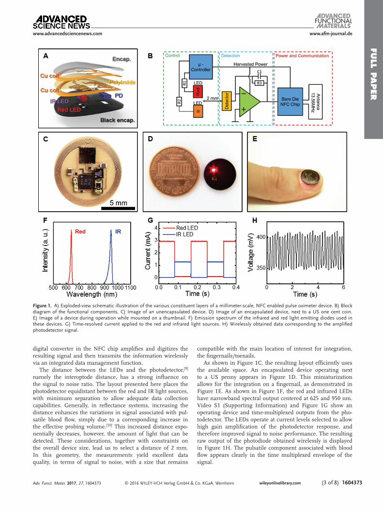
The technology builds on NFC electronic systems recently reported in epidermal formats for data storage, UV sensing, and optical characterization of the skin.[2] Levels of miniaturi-zation needed for fingernail embodiments require rigorous size reduction of the antenna structures (by 13×), decreases in the number of active and passive components (from 22 to 12) and increases in the density of integration (from 32% to 63% in area coverage of active and passive components). The latter aspect is particularly powerful because considerations in lay-outs for soft, biocompatible mechanics are relaxed in minia-turized platforms such as those introduced here, which largely bypass requirements in designs for stretchability. Specifically, the architecture exploits a multilayer layout with a bilayer loop antenna configured to maximize the efficiency for energy har-vesting and the distance for wireless data communication, as in Figure 1A. A dual layer interconnect matrix on a thin substrate affords compact electrical routing between closely spaced com-ponents. A soft opaque material, namely a silicone elastomer (Q1-4010, Dow Corning) with a black dye (5 wt%), with open-ings for the optical components coats the surface of this thin, flexible system (Figure S1, Supporting Information), to facili-tate conformal contact with the target probing area (i.e., finger-nail, toenail, or various skin locations) and to provide protection against mechanical damage.
Integrated functions available in an NFC bare die chip (SL13A, AMS AG) allow significant reductions in the number of components, compared to previously reported systems. As in the simplified schematic illustration of Figure 1B, this chip harvests wirelessly delivered power for operation of a micro-controller and an operational amplifier. The microcontroller drives infrared and red light emitting diodes (LEDs) in a time sequenced manner. A photodetector positioned in between these two LEDs captures the backscattered light. An analog to
Prof. Y. HuangDepartments of Civil and Environmental EngineeringMechanical EngineeringMaterials Science and EngineeringCenter for Engineering and HealthSkin Disease Research CenterNorthwestern UniversityEvanston, IL 60208, USAProf. U. PaikDepartment of Energy EngineeringHanyang UniversitySeoul 133-791, Republic of Korea
Prof. J. A. RogersDepartments of Materials Science and EngineeringBiomedical Engineering, ChemistryNeurological SurgeryMechanical EngineeringElectrical Engineering and Computer ScienceSimpson Querrey Institute & Feinberg Medical SchoolCenter for Bio-Integrated ElectronicsNorthwestern UniversityEvanston, IL 60208, USA
Adv. Funct. Mater. 2017, 27, 1604373
www.afm-journal.de www.advancedsciencenews.com
full p
aper
© 2016 WILEY-VCH Verlag GmbH & Co. KGaA, Weinheim wileyonlinelibrary.com (3 of 8) 1604373
digital converter in the NFC chip amplifies and digitizes the resulting signal and then transmits the information wirelessly via an integrated data management function.
The distance between the LEDs and the photodetector,[9] namely the interoptode distance, has a strong influence on the signal to noise ratio. The layout presented here places the photodetector equidistant between the red and IR light sources, with minimum separation to allow adequate data collection capabilities. Generally, in reflectance systems, increasing the distance enhances the variations in signal associated with pul-satile blood flow, simply due to a corresponding increase in the effective probing volume.[10] This increased distance expo-nentially decreases, however, the amount of light that can be detected. These considerations, together with constraints on the overall device size, lead us to select a distance of 2 mm. In this geometry, the measurements yield excellent data quality, in terms of signal to noise, with a size that remains
compatible with the main location of interest for integration, the fingernails/toenails.
As shown in Figure 1C, the resulting layout efficiently uses the available space. An encapsulated device operating next to a US penny appears in Figure 1D. This miniaturization allows for the integration on a fingernail, as demonstrated in Figure 1E. As shown in Figure 1F, the red and infrared LEDs have narrowband spectral output centered at 625 and 950 nm. Video S1 (Supporting Information) and Figure 1G show an operating device and time-multiplexed outputs from the pho-todetector. The LEDs operate at current levels selected to allow high gain amplification of the photodetector response, and therefore improved signal to noise performance. The resulting raw output of the photodiode obtained wirelessly is displayed in Figure 1H. The pulsatile component associated with blood flow appears clearly in the time multiplexed envelope of the signal.
Adv. Funct. Mater. 2017, 27, 1604373
www.afm-journal.dewww.advancedsciencenews.com
Figure 1. A) Exploded-view schematic illustration of the various constituent layers of a millimeter-scale, NFC enabled pulse oximeter device. B) Block diagram of the functional components. C) Image of an unencapsulated device. D) Image of an encapsulated device, next to a US one cent coin. E) Image of a device during operation while mounted on a thumbnail. F) Emission spectrum of the infrared and red light emitting diodes used in these devices. G) Time-resolved current applied to the red and infrared light sources. H) Wirelessly obtained data corresponding to the amplified photodetector signal.

full
paper
© 2016 WILEY-VCH Verlag GmbH & Co. KGaA, Weinheimwileyonlinelibrary.com1604373 (4 of 8)
Such flexible, miniaturized devices provide advantages in mechanics for mounting on the skin and the nail, due directly to their small size as outlined in quantitative detail in the con-text of previously reported, simple systems with similar form factors. In particular, the small size minimizes sensory per-ception and reduces energy release rates for delamination.[5] The devices can also accommodate bending without signifi-cant change in performance. This tolerance to bending fol-lows from a design that locates the electronic components near the mechanical neutral plane, in the middle of the black encapsulation layer (Figure S2, Supporting Information). The image in Figure 2A shows a device bent to a small radius of curvature. The mechanical properties of the encapsulation layer are important because this material defines the contacting interface. Figure 2B shows the stress–strain curves of various types of encapsulation layers. The low moduli of these materials enable conformal contact with the body and can be selected, independent of the electronics, to match the properties of the target mounting location. A biocompatible adhesive (PC2723U, ScapaHealthcare, UK) bonds the device to the body. Figure 2C shows results from mechanical measurements obtained using a T-peeling tester equipped with a high-resolution force gauge (Mark-10, Copiague, NY, Resolution: ±0.25%, standard ISO 29862:2007) on devices mounted on the fingernail (black line) and the skin (red line). The measurement set-up and method are shown in Figure S3 (Supporting Information). The adhesive ensures strong adhesion to both the fingernail nail (≈9.4 kPa) and the skin (≈7.9 kPa). The low modulus (≈17 kPa) of the encapsulation layer and the strong adhesion provide stable and robust bonding, which eliminates movement artifacts
(Video S2, Supporting Information). The performance is excellent in both flat and bent geometries, as determined by operation while mounted on planar and curved substrates (Figure 2D,E), the latter of which has a 5 mm radious of cur-vature, comparable to the minimum curvature of fingernails in adults.[11] Additionally, the opaque encapsulation layer and its intimate contact provide an excellent shield against ambient light. The radio frequency (RF) properties, as evidenced by the phase response, do not depend strongly on curvature in this range, shown in Figure 2F. The transmission distances highly depend on the input power, size of the reader antenna, and size of the device antenna. Reducing the size of the antenna reduces the transmission distance. Our strategy to minimize this limi-tation involves increasing the Q factor by using a double layer coil and thick, low resistance Cu traces. The result is a Q of ≈16, to enable ≈30 mm distance with a smartphone. The transmis-sion distance can be increased with a high power, large trans-mission antenna. Commercial, long-range reader electronics (30 cm × 30 cm, 4 W input power) allowed >100 mm distance for the miniaturized devices reported here. An additional point of interest is that the devices are washable and water resistant because the copper (Cu) lines (coil, interconnects) are encap-sulated by a layer of polyimide and the entire device is coated by a black silicone elastomer. As a result, the device can even operate when fully submerged in water, as shown in Video S3 (Supporting Information).
Figure 3 displays the results of oximeter measurements per-formed on a fingertip. Figure 3A shows signals recorded for 10 s during a 30 s resting period. Figure 3A, from top to bottom, pre-sents the photodetector response associated with the infrared
Adv. Funct. Mater. 2017, 27, 1604373
www.afm-journal.de www.advancedsciencenews.com
Figure 2. A) Image of the device bent to a small radius of curvature with a pair of tweezers. B) Stress–strain curves of opaque encapsulation layers with various materials. C) Adhesion force measurements performed on encapsulation layers adhered to the nail and the skin. The shaded area indicates the period during peeling (peel rate: 50 µm s−1). Demonstrations of conformal contact with D) a flat surface and E) a curved surface. F) Phase responses and Q factors associated with the flat and curved devices.

full p
aper
© 2016 WILEY-VCH Verlag GmbH & Co. KGaA, Weinheim wileyonlinelibrary.com (5 of 8) 1604373
and red wavelengths, the extracted HR, expressed in beats per minute (BPM), the R-value and the SpO2 level. Descriptions of computational procedures are in the analysis section. Tests that involve holding of one’s breath for 70 s (shaded areas) during data collection with both a miniaturized device and a reference commercial system (IHealth, Apple inc.) on the same subject provides a dynamic SpO2 level comparison of the two systems. The results indicate a change in SpO2 level within a range of ≈87%–98%. From left to right, the graphs summarize the R-value (Figure 3B) and the SpO2 level (Figure 3C) from the miniaturized device, and the SpO2 level from the commercial system (Figure 3D). For the miniaturized device, the equation that links the R-value and SpO2 follows from the modified Lam-bert–Beer equation as outlined in the Experimental Section. The resulting SpO2 levels show behaviors that agree quantita-tively with the commercial system for breath hold tests across multiple subjects. In other words, the system is usable across subjects without the need for recalibration. Table 1 shows the average SpO2 values and standard deviations for measurements conducted continuously for ≈1 min on six different subjects, each in a state of rest. The SpO2 values are all near 99% and the
standard deviations are under 1.5 which is an excellent result for an oximetry system when compared to even more elaborate state of the art devices, which generally provide a 2%–3% toler-ance on SpO2 estimation. All other data are shown in Table S1 (Supporting Information).
Additional studies highlight the unique nature of meas-urements using this type of platform deployed on a fin-gernail/toenail. These measurements are possible, largely
Adv. Funct. Mater. 2017, 27, 1604373
www.afm-journal.dewww.advancedsciencenews.com
Figure 3. A) SpO2 calculation from raw signal obtained from the device on the fingertip. Extracted IR signal. Extracted red signal. Relative values of red and IR signals. Extracted heart rate in beats per minute (bpm). Calculated ratio of red and IR signal (R-ratio). Calculated SpO2. B) R-ratio recorded during a breath hold test. The results show the expected physiological changes. C) Calculated SpO2 during breath hold test showing a visible drop in oxygen saturation. D) Data from a commercial oximeter (IHealth, Apple inc.) simultaneously worn during breath hold test, as a reference. The shaded areas indicate periods of breath holding.
Table 1. Mean and standard deviations (STDs) of calculated SpO2 for multiple subjects.
SpO2 Mean [%] STD
Subject 1 99.9 0.1
Subject 2 98.6 0.6
Subject 3 98.9 0.6
Subject 4 99.8 0.3
Subject 5 99.1 0.2
Subject 6 99.8 0.4

full
paper
© 2016 WILEY-VCH Verlag GmbH & Co. KGaA, Weinheimwileyonlinelibrary.com1604373 (6 of 8)
independent of variations in the shape, thickness, and optical properties of the nail, due to sufficient signal to noise ratio and intimate contact. Figure 4A shows the extraction of the SpO2 from a subject during a 15 s period of no movement followed by a 30 s period of movement of the finger and 15 s period of no movement. Simultaneous recordings from an accelerometer affixed to the finger quantify the movements. The stable extraction of the SpO2 value during movement represents a key advantage. We highlighted the signal sta-bility by drawing a direct comparison to a commercially avail-able oximetry system in Figure S4 (Supporting Information). To further emphasize unique features, especially those that follow from mounting on the fingernail, we compared to results obtained with a commercial reflectance based system
mounted on the wrist, the prevalent location adapted in smart watches and fitness trackers. Data recording occurred over a period of 20 s with the arm held completely still as indi-cated in the accelerometer graphs in Figure S5 (Supporting Information). In the marked area, the fingers of the arm were moved, causing a slight change of the underling probing volume due to the activation of the extensor digitorum and extensor indicis. These changes result in significant distor-tions of the signal seen in Figure S5 (Supporting Informa-tion), making the extraction pulse and SpO2 impossible during activities such as typing on a keyboard. With the sys-tems presented here, such distortions are minimal due to the absence of relative motion between the device, the fingernail, and the underlying soft tissue.
Adv. Funct. Mater. 2017, 27, 1604373
www.afm-journal.de www.advancedsciencenews.com
Figure 4. Demonstration of device operation during movement and on various body locations. A) Calculated SpO2 during periods of 15 s of rest, 30 s of movement, and 15 s of rest. The movement is quantified by the output of a X, Y, Z-axis accelerometer. B) Demonstration of a possible applica-tion in which a computer mouse serves as the wireless interface. C) Relative values of red and IR signal obtained from mounting on the fingernail. D) Calculated SpO2 from the fingernail. E) Demonstration of mounting on the back of the earlobe. The inset shows the front of the earlobe during the device operation. F) Relative values of red and IR signal obtained from the earlobe. G) Calculated SpO2 from the earlobe.

full p
aper
© 2016 WILEY-VCH Verlag GmbH & Co. KGaA, Weinheim wileyonlinelibrary.com (7 of 8) 1604373Adv. Funct. Mater. 2017, 27, 1604373
www.afm-journal.dewww.advancedsciencenews.com
These devices can be used in a diverse range of scenarios not only on the fingernail but also on other regions of the body such as the earlobe. In the former case, a computer mouse can be equipped with NFC reader capabilities, allowing for continuous, or nearly continuous, measurements during use of the computer, as in Figure 4B. Also, smartphones and tab-lets can be potential platforms for continuous monitoring during common daily activities because of their frequent use. Figure 4C,D shows the extracted photodetector signals and the SpO2 level, respectively, captured from a device mounted on the fingernail. The full data set is in Figure S6 (Supporting Infor-mation). In the latter case, i.e., the back of an earlobe, an NFC interface in a smartphone can enable data collection during phone calls as shown in Figure 4E. Figure 4F,G shows data captured in this mode. This hard-to-reach mounting location, inaccessible to conventional systems, also provides discretion for long-term measurement as the oximeter is not easily vis-ible (Video S4, Supporting Information). The full data set is in Figure S7 (Supporting Information).
3. Conclusion
The results reported here provide the foundations for mil-limeter-scale, battery-free optoelectronic systems capable of wirelessly capturing photoplethysmograms and quantitative information on blood oxygenation, heart rate, and heart rate variability. When implemented with a soft, optically opaque encapsulation material, the systems are thin, lightweight, and mechanically compliant, thereby providing great versatility in choice of mounting location. Operation on the fingernail, in particular, is highly desirable for long-term operation, with minimized motion artifacts and risks for irritation. Extensions of this platform should allow additional modes of operation with relevance to clinical medicine and human health.
4. Experimental SectionDevice Fabrication: Fabrication of the coils involved photolithography
and wet etching to define traces on both sides of a Cu (18 µm)/polyimide (PI, 12 µm)/Cu (18 µm) foil. Via connections for the circuit and the coil were formed by electroplating through corresponding holes, defined lithographically. After removal of native oxide layers, a thinned NFC bare die (SL13A, AMS AG, 100 µm) with Au ball-bumps to enhance solderability and other electrical components was attached to the Cu traces with an In/Ag soldering paste (Ind. 290, Indium Corporation). The encapsulation layer consisted of a silicone elastomer (Q1-4010, Dow Corning) with a black dye (5 wt%).
Components: The critical components are as follows: NFC (SL13A, AMS AG, 2.36 mm × 2.36 mm × 0.1 mm), microcontroller (ATtiny10, Atmel, 2 mm × 2 mm × 0.6 mm), amplifier (ADA 4505-2, Analog Devices, Inc, 1.42 mm × 1.42 mm × 0.6 mm), IR LED (SFH 4043, 950 nm, Osram Opto Semiconductor, 1 mm × 0.5 mm × 0.45 mm), red LED (LR QH9F, 625 nm, Osram Opto Semiconductor, 1 mm × 0.5 mm × 0.35 mm), and photodetector (EMD7000 × 01, Vishay Semiconductors, 2 mm × 1.25 mm × 0.85 mm).
Programming: Programming of the microcontroller (ATTiny10) emphasized low power operation and accurate time management. The code was written in C programming language and was compiled using Atmel studio7. The microcontroller was programmed using an Atmel in-circuit emulator (ICE) joint test action group (JTAG) programming system before system assembly.
Pulse Oximeter In Vivo Measurements: The wireless pulse oximeter was tested on human subjects and compared to a commercial system (IHealth, Apple inc.). The device reported here uses reflection mode and it was placed on the middle finger tip. The commercial transmittance system was placed on the index finger tip. Both systems were placed on the subjects’ right hand. Arterial oxygen saturation was determined over a measurement period of 30 s on four subjects, each at rest. A breath holding task was performed for purposes of comparison over a range of saturation levels (85%–98%).
Additional measurements involved mounting on the fingertip, fingernail, and earlobe of one participant.
Pulse Oximeter Data Analysis: The Pulse Oximeter data analysis was performed offline using a commercial software package (MATLAB R2013b, The MathWorks Inc.). The data collection involved a sampling rate of 25 Hz, with characteristic alternating output levels corresponding to switching between the two LEDs (12 Hz, red: 640 nm, infrared: 950 nm). These levels were extracted using a local minima–maxima finding algorithm. This procedure provided a sampling rate of 6 Hz for each wavelength. Resulting time dependent variations in signal were reconstructed by spline interpolation of the sampled points.[12] Each wavelength signal was bandpass filtered (0.5–3 Hz, 10th order Butterworth digital filter) to extract the pulsating component (AC(t)) and low-pass filtered (0.2 Hz, 10th order Butterworth digital filter) to extract the slow signal component unrelated to pulsation (DC(t)). The relative pulsatile signal intensity S(t) was computed as the ratio of the two signals for both the red and the infrared wavelengths
( )AC( )DC( )
S ttt
=
(1)
The ratio R(t) between the red and infrared pulsatile components[13] was computed every second over an integration time window of 5 s as
( )In(rms( ( ) ) 1)In(rms( ( ) ) 1)
R
IRR t
S TS T
= ++
(2)
for T from t − 2.5 to t + 2.5 s, where ln is the natural logarithm operator, rms is the root mean square operator, and S(t)R and S(t)IR are the red and infrared relative pulsatile signal, respectively.
From photon-diffusion analysis and the modified Lambert–Beer equation,[14] the following equation can be derived for the relationship between the arterial blood saturation SpO2 and the R(t) value[15]
SpO ( ) =( )DPF ( ) ( )
( ) ( ) DPF ( ) ( ) ( )2
Hb R R IR IR
Hb R HbO R R IR HbO IR Hb IR
Hb
2 2
tR t
R t
ε λ λ
ε λ ε λ ε λ ε λ− + −
ε− −
− (3)
where ( )HbO R2ε λ and εHb(λR) are the extinction coefficients of oxy- and
deoxyhemoglobin for red light (wavelength of 640 nm) and ( )HbO IR2ε λ
and εHb(λIR) are the extinction coefficients of oxy- and deoxyhemoglobin for infrared light (wavelength of 950 nm). The extinction coefficients of the two forms of hemoglobin at the two wavelengths were extracted from ref. [16] ( ( )HbO R2
ε λ = 0.011 mm−1, εHb(λR) = 0.106 mm−1, ( )HbO IR2
ε λ = 0.028 mm−1, εHb(λIR) = 0.018 mm−1). The quantity DPFR−IR describes the effects of the dissimilar optical path lengths at the two wavelengths and can be expressed as the ratio of the differential path length factors[17] (DPFs) of the red and infrared lights DPF DPF /DPFR IR R IR=− . The color dependence of the optical path length depends on the scattering nature of the biological tissue and its dependence on the light wavelength. If DPFR−IR is considered equal to 1, Equation (3) is identical to the one derived using the simple Lambert–Beer law. This approximation, however, provides a poor estimate of SpO2. A practical problem when using Equation (3) for SpO2 estimation is that DPFR−IR depends on the baseline optical properties of the tissue (namely reduced scattering coefficient and absorption coefficient at the two wavelengths), and thus on tissue microstructure and, importantly, on SpO2 itself.[18] This issue is generally overcome by calibrating the oximeter empirically. If the range of saturation value is small (80%–100%), a constant DPFR−IR can be considered. Based on literature and empirical

full
paper
© 2016 WILEY-VCH Verlag GmbH & Co. KGaA, Weinheimwileyonlinelibrary.com1604373 (8 of 8) Adv. Funct. Mater. 2017, 27, 1604373
www.afm-journal.de www.advancedsciencenews.com
results from our measurements, we set the DPFR−IR to DPFR−IR = 1.4.[18,19] This value accounted for the increased optical path length of red light compared to infrared light. Equation (1) yielded arterial oxygen saturation levels close the one reported by the commercial system on different subjects and in the range of saturation investigated (85%–100%). A different calibration curve might be needed (one in which DPFR−IR is not considered constant) for measurements over an expanded range of saturation values. In this paper, an extracted BPM signal BPM(t) is reported for some data. The time dependence of BPM was estimated as
BPM( ) 60 ( )max IRt f t= − (4)
where f(t)max–IR was the frequency at which fft(S(T)IR) presented its maximum for T from t − 2.5 to t + 2.5 s. fft is the fast Fourier transform operator.
Supporting InformationSupporting Information is available from the Wiley Online Library or from the author.
AcknowledgementsJ.K. and P.G. contributed equally to this work. This work was supported by funding from the Simpson Querrey Institute (SQI) Center for Bio-Integrated Electronics, and used facilities in the Frederick Seitz Materials Research Laboratory and the Center for Microanalysis of Materials at the University of Illinois at Urbana-Champaign. Z.X. and X.F. acknowledge the support from the National Basic Research Program of China (Grant No. 2015CB351900) and National Natural Science Foundation of China (Grant Nos.11402134 and 11320101001). Y.H. acknowledges the support from National Science Foundation (Grant Nos. DMR-1121262, CMMI-1300846, CMMI-1400169, and 1534120) and the National Institutes of Health (Grant No. R01EB019337).
Received: August 23, 2016Revised: September 19, 2016
Published online: November 25, 2016
[1] a) T. Yokota, P. Zalar, M. Kaltenbrunner, H. Jinno, N. Matsuhisa, H. Kitanosako, Y. Tachibana, W. Yukita, M. Koizumi, T. Someya, Sci. Adv. 2016, 2, e1501856; b) C. M. Lochner, Y. Khan, A. Pierre, A. C. Arias, Nat. Commun. 2014, 5, 5745.
[2] J. Kim, G. A. Salvatore, H. Araki, A. M. Chiarelli, Z. Xie, A. Banks, X. Sheng, Y. Liu, J. W. Lee, K.-I. Jang, S. Y. Heo, K. Cho, H. Luo, B. Zimmerman, J. Kim, L. Yan, X. Feng, S. Xu, M. Fabiani, G. Gratton, Y. Huang, U. Paik, J. A. Rogers, Sci. Adv. 2016, 2, e1600418.
[3] D. H. Kim, N. S. Lu, R. Ma, Y. S. Kim, R. H. Kim, S. D. Wang, J. Wu, S. M. Won, H. Tao, A. Islam, K. J. Yu, T. I. Kim, R. Chowdhury, M. Ying, L. Z. Xu, M. Li, H. J. Chung, H. Keum, M. McCormick, P. Liu, Y. W. Zhang, F. G. Omenetto, Y. G. Huang, T. Coleman, J. A. Rogers, Science 2011, 333, 838.
[4] J. Kim, A. Banks, H. Cheng, Z. Xie, S. Xu, K. I. Jang, J. W. Lee, Z. Liu, P. Gutruf, X. Huang, P. Wei, F. Liu, K. Li, M. Dalal, R. Ghaffari, X. Feng, Y. Huang, S. Gupta, U. Paik, J. A. Rogers, Small 2015, 11, 906.
[5] J. Kim, A. Banks, Z. Xie, S. Y. Heo, P. Gutruf, J. W. Lee, S. Xu, K. I. Jang, F. Liu, G. Brown, J. Choi, J. H. Kim, X. Feng, Y. Huang, U. Paik, J. A. Rogers, Adv. Funct. Mater. 2015, 25, 4761.
[6] K. K. Tremper, Chest J. 1989, 95, 713.[7] J. E. Sinex, Am. J. Emerg. Med. 1999, 17, 59.[8] Y.-S. Yan, Y.-T. Zhang, IEEE Trans. Inf. Technol. Biomed. 2008, 12, 399.[9] J. L. Reuss, IEEE Trans. Biomed. Eng. 2005, 52, 153.
[10] Y. Mendelson, B. D. Ochs, IEEE Trans. Biomed. Eng. 1988, 35, 798.[11] S. Murdan, Int. J. Cosmet. Sci. 2011, 33, 509.[12] C. De Boor, C. De Boor, E.-U. Mathématicien, C. De Boor, C. De Boor,
A Practical Guide to Splines, Vol. 27, Springer-Verlag, New York 1978.[13] J. P. Dekock, L. Tarassenko, Med. Biol. Eng. Comput. 1993, 31, 291.[14] A. Sassaroli, S. Fantini, Phys. Med. Biol. 2004, 49, N255.[15] a) J. M. Schmitt, IEEE Trans. Biomed. Eng. 1991, 38, 1194; b) D. R. Tobler,
M. K. Diab, R. J. Kopotic, U.S. Patent No. 6,285,896, 2001.[16] W. Zijlstra, A. Buursma, W. Meeuwsen-Van der Roest, Clin. Chem.
1991, 37, 1633.[17] F. Fabbri, A. Sassaroli, M. E. Henry, S. Fantini, Phys. Med. Biol.
2004, 49, 1183.[18] J. Kohl, G. Noci, E. Antonucci, G. Tondello, M. Huber, S. Cranmer,
L. Strachan, A. Panasyuk, L. Gardner, M. Romoli, Astrophys. J. Lett. 1998, 501, L127.
[19] F. Scholkmann, U. Gerber, M. Wolf, U. Wolf, Neuroimage 2013, 66, 71.