Mechanical Properties of Dental Materials
96
MECHANICAL PROPERTIES OF DENTAL MATERIALS
Transcript of Mechanical Properties of Dental Materials
MECHANICAL PROPERTIES
OF DENTAL MATERIALS

1. INTRODUCTION
2. TYPES OF STRESS
3. STRAIN
4. STRESS STRAIN RELATIONSHIP
5. PROPORTIONAL LIMIT
6. ELASTIC LIMIT
7. YOUNG’S MODULUS
8. RESILIENCE
9. FLEXIBILITY
CONTENTS

10. YIELD STRESS
11. TOUGHNESS
12. DUCTILITY AND MALLEABILITY
13. FRACTURE TOUGHNESS
14. ULTIMATE STRENGTH
15. COMPRESSIVE STRENGTH
16. TENSILE STRENGTH, DIAMETRAL TENSILE STRENGTH
17. SHEAR STRENGTH
18. FLEXURAL STRENGTH
19. FATIGUE STRENGTH
CONTENTS

In the oral environment, restorations are subjected
to heavy masticatiory forces. These forces act on
teeth and/ or material producing different reactions
that lead to deformation, which can ultimately
compromise their durability over time.
It is important to introduce some concepts that are
extremely relevant to understand the performance
presented by such materials under specific test
conditions.
INTRODUCTION
Mechanical properties are subset of physical
properties that are based on the laws of mechanics
that is the physical science that deals with energy
and forces and their effects on the bodies.
These properties are expressed most often in units
of stress and strain.
DEFINITION

When an external force is applied to acts a body, an
internal force, equal in magnitude and opposite in
direction to the applied force is set up in the body.
This internal resistance to the external force is
called “STRESS”
Denoted by “S” or “σ”
Designated as force per unit area (σ=N/m²)
Commonly stress is reported in terms of mega
Pascals. Where, Pascal = 1 N / m².
STRESS
Depending on the type of force applied,
following stresses are produced
A. Axial (Tensile and Compressive )
B. Shear (sliding)
C. Flexural
TYPES OF STRESS

When a body is subjected to compressive forces (two
axial sets of force are applied to a sample directed
towards each other in a straight line, in order to
approximate the molecular structure of the material, an
internal resistance developed in the body to oppose this
force is called compressive stress.
COMPRESSIVE STRESS
Compressive force
Compressive stress

DEFINITION OF COMPRESSIVE STRESS:
Ratio of compressive force to cross-sectional area
perpendicular to the axis of applied force OR It is
the force per unit area produced in the body in
response to an externally applied force, which
tends to compress (shorten) the material.
It is accompanied by compressive strain.

Since most of masticatory forces are compressive
in nature, it is important to investigate materials
under this condition.
Tooth Average masticatory force (N)
Second molar 800
First molar 390
Bicuspids 288
Cupids 208
Incisors 155
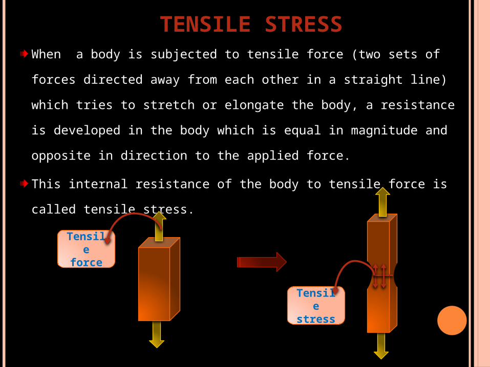
When a body is subjected to tensile force (two sets of
forces directed away from each other in a straight line)
which tries to stretch or elongate the body, a resistance
is developed in the body which is equal in magnitude and
opposite in direction to the applied force.
This internal resistance of the body to tensile force is
called tensile stress.
TENSILE STRESS
Tensile stress
Tensile force

DEFINITION OF TENSILE STRESS
It is the force per unit area produced in the body in
response to an externally applied force, which
tends to stretch(elongate ) the material.
It is accompanied by tensile strain.
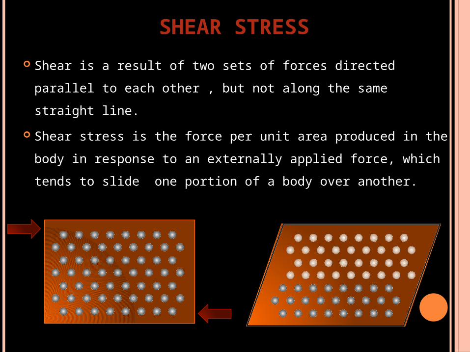
Shear is a result of two sets of forces directed parallel
to each other , but not along the same straight line.
Shear stress is the force per unit area produced in the
body in response to an externally applied force, which
tends to slide one portion of a body over another.
SHEAR STRESS

Tensile and compressive stresses along with shear,
are the three simple examples of stress which
form the basis of all other more complex stress
patterns.FLEXURAL STRESS:
Also called as bending stress.
Produced by bending forces over the dental
appliance.
COMPLEX STRESSES

STRAIN The application of an external force to a body results in
a change in dimension of that body. The magnitude of
which depends on the applied force and the properties
of the material.
The numerical value of strain is given by the
expression
Strain = Change in length/Original length.=L/L
Strain is dimensionless quantity because a unit length
is divided by unit length.

The stain may be recoverable, that is the material
will return to its original length after removal of the
applied force (elastic strain), or the material may
remain deformed, in which case the strain is non-
recoverable(plastic strain).
A third possibility is that the strain may be partially
recoverable(visco elasticity).

STRESS-STRAIN RELATIONSHIP
Each type of stress is capable of producing a
corresponding deformation in the body.
Therefore, stress and strain are not independent and
unrelated properties, but they are closely related and
may be seen as cause and effect.
The relationship of stress and strain is often used to
characterize the mechanical properties of materials.
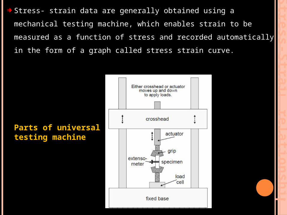
Stress- strain data are generally obtained using a mechanical
testing machine, which enables strain to be measured as a
function of stress and recorded automatically in the form of a
graph called stress strain curve.
Stre
ss-S
train
rela
tion
sh
ip
Parts of universal testing machine

Click on it to watch a video related to tensile test and stress strain graph

Stress strain curve for a hypothetical material subjected
to increased tensile stress until failure is shown in the
figure.

As the stress is increased, the strain is increased. In the initial
portion of the curve, from O to A, the strain is linearly
proportional to the stress. When a stress that is higher than the
value registered at A is achieved, the strain changes are no
longer linearly proportional to the stress changes. Hence the
value of the stress at A is known as the proportional limit.
O
Proportional limit
Ultimate tensile strength
Str
ess
dir
ectl
y pro
port
ional
to s
trai
nStr
ess
Strain
yA
PROPORTIONAL LIMIT

Proportional limit is defined as the greatest stress that a
material will sustain without deviation from the linear
proportionality of stress to strain

Defined as the maximum stress that a material can
withstand without permanent deformation.
Above elastic limit, a material undergoes irreversible
plastic deformation and below the elastic limit, it
shows reversible elastic deformation.
NOTE
Elastic deformation → Bonds stretched→ No permanent
damage
Plastic deformation → Bonds broken→ Permanent damage
ELASTIC LIMIT
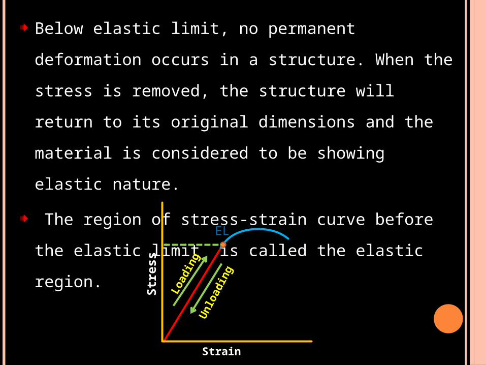
Below elastic limit, no permanent deformation
occurs in a structure. When the stress is removed,
the structure will return to its original dimensions
and the material is considered to be showing elastic
nature.
The region of stress-strain curve before the elastic
limit is called the elastic region.
Str
ess
Strain
Loadin
g
Unlo
adin
g
EL

The application of stress greater than elastic limit
results in permanent or irreversible strain in the
specimen and the region of the stress strain curve
beyond the elastic limit is called the plastic region. S
tress
Strain
EL
Elastic Deformation Plastic Deformation

For linearly elastic materials which obey Hooke’s
law(stress directly proportional to strain) the elastic limit
and proportional limit represent the same stress within
the structure and the terms are often used
interchangeably in referring to the stress involved.
Super elastic materials are exception to this.
These materials exhibit nonlinear elastic behavior,
and their relationship between stress and strain in the
elastic region does not follow a straight line, but
removal of the load results in a return to zero strain.

P
E
P- Proportional limit
E- Elastic limit
A-Yield strength
Super elastic material
NOTE :
Fundamental difference in the concept of
proportional and elastic limit is one deals with
proportionality of strain to stress in the structure,
whereas the other describes elastic behavior of the
material.

There are several important mechanical properties
measuring reversible deformation and include
1) Elastic modulus ( young’s modulus or modulus of
elasticity or Hooke’s law )
2) Dynamic young’s modulus
3) Flexibility
4) Resilience
5) Poisson’s ratio
MECHANICAL PROPERTIES BASED ON ELASTIC DEFORMATION

When a material deforms elastically, strain for a given
stress is always the same and the two are related by
Hooke´s Law (stress is directly proportional to strain):
=E
E=
where,
σ is stress [ MPa ]
E modulus of elasticity
/constant of proportionality
[MPa]
ε strain [unitless or %]
YOUNG’S MODULUS / ELASTIC MODULUS / MODULUS OF ELASTICITY

From the Hooke’s law the modulus of elasticity is
defined as the ratio of the stress to the strain in the
linear or elastic portion of stress strain curve.
E is measured by the slope of stress strain graph.
It desribes relative stiffnes or rigidity of a material.

Therefore, it follows that lesser the strain for a given
stress, greater will be the stiffness and higher the Young’s
modulus (E) and viceversa.
Str
ess
Strain
Greater E Stiffness Lesser E flexiblility Str
ess
Strain
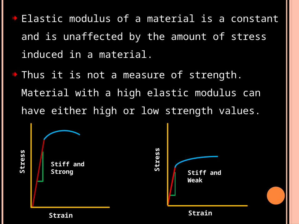
Elastic modulus of a material is a constant and is
unaffected by the amount of stress induced in a
material.
Thus it is not a measure of strength. Material with a
high elastic modulus can have either high or low
strength values.
Str
ess
Strain
Stiff andStrong Stiff and
Weak
Str
ess
Strain

APPLICATIONS
The metal frame of a metal-ceramic bridge should
have a high stiffness. If the metal flexes, the
porcelain veneer on it might crack or separate. Such
a material would possess a comparative high
modulus of elasticity.
A polyether material have greater stiffness than all
other elastomeric impression materials. Thus a
greater force is needed to remove a impression tray
from undercuts in mouth.

NOTE:
The modulus of elasticity is an inherent property of
the material and cannot be altered appreciably by
heat treatment, work hardening, or any other kind of
conditioning.
This property is called structure insensitivity.
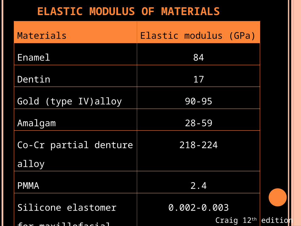
ELASTIC MODULUS OF MATERIALS
Materials Elastic modulus (GPa)
Enamel 84
Dentin 17
Gold (type IV)alloy 90-95
Amalgam 28-59
Co-Cr partial denture
alloy
218-224
PMMA 2.4
Silicone elastomer for
maxillofacial prosthesis
0.002-0.003
Feldspathic porcelain 69-70 Craig 12th edition

Can be measured by dynamic method.
Ultrasonic longitudinal and transverse wave
transducers and appropriate receivers are used.
The velocity of sound wave and density of material
are used to calculate elastic modulus.
DYNAMIC YOUNG’S MODULUS
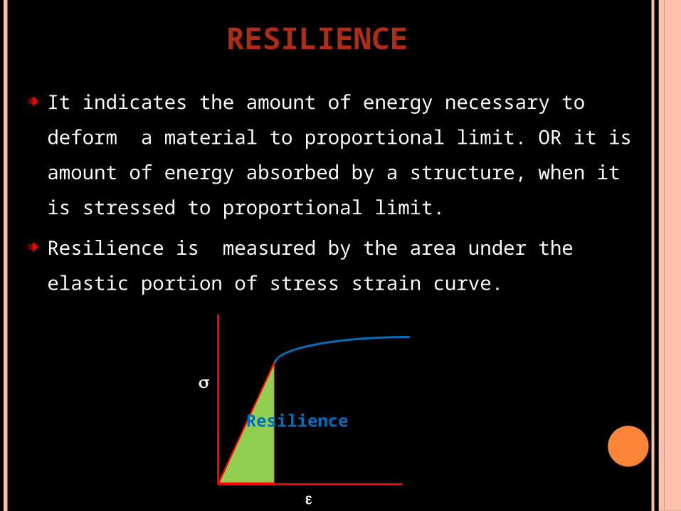
It indicates the amount of energy necessary to deform a
material to proportional limit. OR it is amount of energy
absorbed by a structure, when it is stressed to
proportional limit.
Resilience is measured by the area under the elastic
portion of stress strain curve.
Resilience
RESILIENCE

Resilience has particular importance in the evaluation
of orthodontic wires . It determines the magnitude of
the force that can be applied to the tooth and how far
the tooth can move before the spring is no longer
effective.
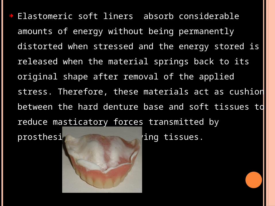
Elastomeric soft liners absorb considerable amounts of
energy without being permanently distorted when stressed
and the energy stored is released when the material springs
back to its original shape after removal of the applied
stress. Therefore, these materials act as cushion between
the hard denture base and soft tissues to reduce
masticatory forces transmitted by prosthesis to the
underlying tissues.

If large proximal strains are developed during
compressive loading, a proximal inlay might absorb
the energy and cause excessive movement of the
adjacent tooth when the absorbed energy is
released.
Hence the restorative material should exhibit a
moderately high elastic modulus and relatively low
resilience.

It is the maximum elastic (recoverable) strain that occurs
when a material is stressed to proportional limit.
Therefore, it follows that greater the strain for a given
stress in a material, greater will be it’s flexibility.
Flexibility
Proportional limit
FLEXIBILITY
APPLICATIONS:
Restorative materials should withstand high stresses
and show minimum distortion or should have
minimum flexibility.
Impression materials should have large flexibility or
elastic deformation to withdraw through severe
undercuts without permanent deformation.
Maxillofacial materials and soft denture reliners
should have high flexibility.

There are several important mechanical properties
measuring irreversible deformation and include
1) Yield strength
2) Toughness
3) Ductility and malleability
4) Fracture toughness
5) Ultimate tensile strength
6) Fracture strength
MECHANICAL PROPERTIES BASED ON PLASTIC DEFORMATION

When a tensile force is applied along one axis to
produce elongation, compressive strain is produced at
right angles, proportionately.
Within elastic range the ratio of lateral to the axial
strain is called Poisson's ratio.
Dental materials have Poisson's ratio
value in range of 0.3 to 0.5.
POISSON’S RATIO

Irregularities along the straight line region of the
stress versus-strain plot may represent minor
deviations from Hooke’s law and cause some
uncertainty in determining the precise point at
which the selected line deviates from
linearity(proportional limit).
Thus a different property, yield strength, is used in
cases where the proportional limit cannot be
determined with sufficient accuracy.
YIELD STRENGTH (PROOF STRESS)

Yield Strength
Str
ess
0.002 0.004 Strain
Yield strength is the stress required to produce a small-
specified amount of plastic deformation.
To determine the YS for a material at 0.2% offset, a line is
drawn parallel to the straight line region, starting at a value
of 0.002, or 0.2% of the plastic strain, along the strain axis
and is extended until it intersects the stress-strain curve.
The stress corresponding to this point is the yield strength.

Yield strength indicates a functional failure of a material.
Although the term strength implies that the material has
fractured, it is actually intact but has sustained a specific
amount of plastic strain (deformation)
A restoration exhibiting a permanent deformation will be
no more serving the purpose in spite of the fact that it
didn’t fracture.
Yield stress is more important than the ultimate stress,
because yield stress represents the clinical failure.
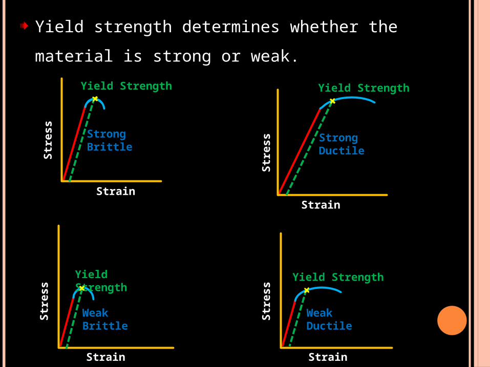
Yield strength determines whether the material is
strong or weak.S
tress
Strain
Yield Strength
Strong Brittle
Str
ess
Strain
Yield Strength
Strong Ductile
Str
ess
Strain
Yield Strength
WeakBrittle
Str
ess
Strain
Yield Strength
Weak Ductile
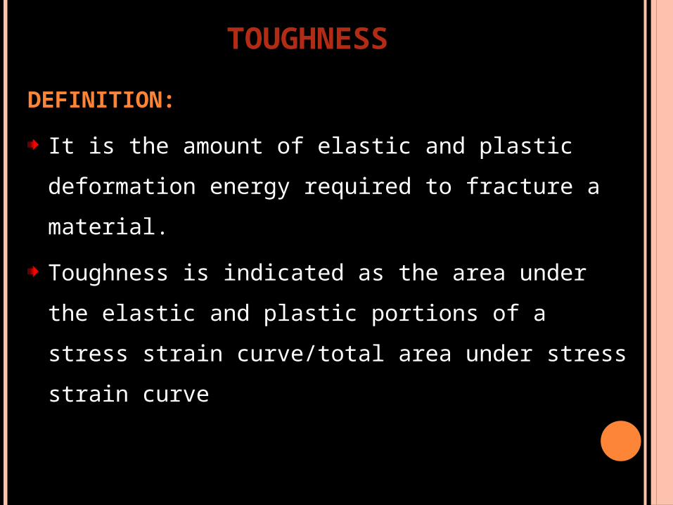
DEFINITION:
It is the amount of elastic and plastic deformation
energy required to fracture a material.
Toughness is indicated as the area under the elastic
and plastic portions of a stress strain curve/total
area under stress strain curve
TOUGHNESS

Difference between resilience and toughness
TOUGHNESSStr
ess
Strain
Proportional limit
Toughness is the total amount of energy a material can
absorb up to the point of fracture.
Whereas resilience represents the energy required to stress
a material to it’s proportional limit OR The maximum amount
of energy a material can absorb without undergoing
permanent deformation.
Str
ess
Strain
RESILIENCE
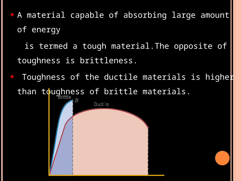
A material capable of absorbing large amount of
energy
is termed a tough material.The opposite of toughness
is brittleness.
Toughness of the ductile materials is higher than
toughness of brittle materials.

Toughness is not as easy to calculate as resilience,
and the integration is done numerically.
If a sample is being tested with an automated rig
attached to data logging equipment then the
toughness can be reported at the end of the run.
In case of a complex curve however there is little
choice but to count the squares under the curve.

Each large square is 50 MPa x 0.1% (0.001) = 50,000 J m-3.
Each small square is 1/100th of this (500 J m-3).
Sample A: large squares = 0, small squares = 195 => 97.5
kJ m-3.
Sample B: large squares = 26, small squares = 816
=> 1.71 MJ m-3.

DEFINITION
Relative ability of a material to deform physically under
a tensile stress before it fractures.
Ductility represents the ability of a material to sustain
large permanent deformation under tensile load before
it fractures. For example, a metal that can be drawn
readily into a long, thin wire is considered to be ductile.
A material that undergoes very little plastic deformation
is brittle.
DUCTILITY

Ductility(elongation) can measured with an extensometer
while the material is being tested or calculated from the stress
strain curve by drawing a line from the point of fracture, that
is parallel to the elastic region of the stress- strain
curve.Where this line meets the strain axis is the measure of
the ductility of the material, and is frequently presented in
terms of percentage elongation.
DUCTILITY
Ela
stic
regio
n
Str
ess
Strain
Yield Strength
Fracture

Percent elongation gives an indication of the
workability of an alloy and is calculated as follows
% elongation=(Increase in length/Original
length)X100
Alloys Percentage elongation
Ni-Cr 2.4
Co-Cr 1.5
Co-Ni-Cr 8-10

Ductility is otherwise measured by 3 common methods
a) Percent elongation after fracture:
The simplest and most commonly used method is to
compare the increase in length of a wire or rod after
fracture in tension to its length before fracture.
Two marks are placed on the wire as the gauge length (for
dental, materials, the standard gauge length is usually
51mm) the wire or rod is then pulled a part under a
tensile load.
The fractured ends are fitted together, and the
gauge length is again measured, the ratio of the
increase in length after fracture to the original
gauge length is called the present elongation and
represents ductility.

b) The reduction in area of tensile test specimens:
The necking or cone-shaped constriction that occurs at
the fractured end of a ductile wire after rupture under
tensile load, the percentage of decrease in cross-
sectional area of the fractured end in comparison to the
original area of the wire or rod is referred to as the
reduction in area.

c) The cold bend test:
The material is clamped in a vise and bent around a
mandrel of specified radius, the number of bends to
fracture is counted, with the grater the number, the
greater is the ductility of the material.

Materials that experience a large amount of permanent
deformation are said to be ductile.
Materials that undergo little or no plastic behavior are
said to be brittle. A brittle material fractures at or near its
proportional limit.
Str
ess
Strain
Str
ess
Strain
Brittle
Ductile

Importance of ductility in dentistry:
Clasps can be adjusted, orthodontics appliances
can be prepared, crowns or inlays can be
burnished if they are prepared from alloys of high
values of percentage elongation.
Open margin
Burnishing

DEFINITION
The ability of a material to sustain considerable
permanent deformation without rupture under
compression, as in hammering or rolling into a
sheet, is termed malleability.
Gold is most ductile and malleable and silver
stands the second.
Platinum is third most ductile and copper is third
most malleable.
MALLEABILITY

Ductility of metals in
decreasing order
Malleability metals in
decreasing order
Gold Gold
Silver Silver
Platinum Aluminum
Iron Copper
Nickel Tin
Copper Platinum
Aluminum Lead
Zinc Zinc
Tin ironCraig 12th edition

DEFINITION:
Fracture toughness is the resistance of a brittle
material to catastrophic propagation of flaws
under an applied stress.
Fracture toughness is an indication of the amount
of stress required to propagate a preexisting flaw.
FRACTURE TOUGHNESS

Flaws or cracks may arise naturally in a material or
nucleate after time in service.
In either case, any defect generally weakens a
material, and as a result, sudden fractures can arise
at stresses below the yield stress.
Sudden catastrophic fractures typically occur in
brittle maerials that do not have ability to
plastically deform and redistribute stresses.
It is imperative to realize that ceramics, in contrast
to metals, are brittle materials and are known to
undergo catastrophic failure due to inherent flaws.
For them strength is more of a “conditional” than an
inherent material property.
Therefore, strength data alone cannot be directly
extrapolated to predict structural performance.
Resistance to fracture in ceramics is determined by
fracture toughness.

DEFINITION:
It can be defined as the maximum stress a material can
withstand before failure in compression, tension , shear
or flexure loading. It is the highest point on stress strain
curve and corresponds to necking in ductile materials.
It is often different from the fracture strength which is
the stress at the point of fracture.
ULTIMATE STRENGTH
Ultimate strength
Fracture strength
Str
ess
Strain
An alloy that has been stressed to near ultimate
strength will be permanently deformed, so a
restoration receiving that amount of stress during
function would be useless.
The yield strength is often of greater importance
than ultimate tensile strength because it is a
estimate of when a material will start to deform
permanently.
For ductile materials, the tensile strength can be
measured directly using tensiometer or dumbbell
shaped cylindrical specimen, is clamped rigidly at
the ends and pulled apart to fracture.
Brittle materials may fracture at clamping points
due to stress concentrations.
TENSILE STRENGTH

MATERIALS TENSILE STRENGTH
Dental porcelain 50-100 MPa
Amalgam 27-55 MPa
Resin- Based composite 30-90MPa
Alumina ceramic 120MPa
This test is especially useful for brittle materials like
cements and ceramics.
The small size of some dental restorations has
made the preparation of large dumbbell shaped
tensile specimens impractical and also clamping
stress during testing of small tensile specimens of
plastics and ceramics frequently cause premature
fracture.
As a result, the tensile properties of these materials
are usually estimated by the diametral tensile test.
DIAMETRAL TENSILE STRENGTH

This test involves diametric compression of a disc
with a thickness one-half its diameter between two
plates until fracture occurs. The compressive force
introduces tensile stresses normal to the diameter
under load, and failure is tensile in character.
The tensile strength is calculated
as =2P / DT
Where,
P load
D Diameter of the disc
T Thickness of the disc
Tension
P
P
Fracture plane T

It is the ability of a material to withstand axial
forces.
The sample of the material to be tested is
constructed in the shape of a cylinder of known
dimensions, usually 6x4 mm in diameter. It is then
conditioned for up to 24hrs at mouth temperature
and often in water to simulate intraoral conditions
after placement.
The cylinder is placed between the platens of a load
testing machine and the upper paten is driven down
at a constant speed until the specimen fractures.
COMPRESSIVE STRENGTH

The ultimate load applied over the surface area is then
calculated. To reduce the variation that may occur during
specimen preparation, a number of specimens are produced
and tested.
The mean of the values at fracture
are used to determine the
compressive strength of the material.

1. The test for compressive strength is not a good
discriminator between different material types.
The manner in which the test is carried out is
obviously not representative of what occurs in the
mouth. When masticatory load is applied to the
restoration, the tooth tissue surrounding the
restoration will act as a support and help
withstand the occlusal forces encountered.
DRAWBACKS OF THE COMPRESSIVE TEST

2. As the sample is constrained by friction at points
of contact with the platens of the tester, there is
an increase in the cross sectional area, with the
material taking up a barrel shape.
This gives rise to complex stress pattern in a
material that cannot be analyzed easily, which
makes the interpretation of compression test very
difficult.

Material Compressive strength
(MPa)
Enamel 384
Dentin 297
Amalgam 189
Feldspathic porcelain 149
Resin composite 225
Conventional GIC 180-200
Resin modified GIC 170-200

It is the maximum
shearing stress at shear
failure. push-out or punch
test method, (i.e. applying
an axial load to push out a
sample through the other
side is used in this test.
SHEAR STRENGTH
Shear load
Resin
cement
Acrylic resin
Lithium Disilicate
The flexural strength of a material is its ability to bend
before it breaks.
Flexural stress is produced by bending forces and may
generate all three types of stress in a structure.
FLEXURAL STRENGTH/ TRANSVERSE BENDING (3- POINT BENDING)/ (MODULUS OF RUPTURE):

It can occur in fixed partial dentures or cantilever
structures.
Lower portion of the beam is in tension, upper
portion is in compression and sides reveal
shear stresses.
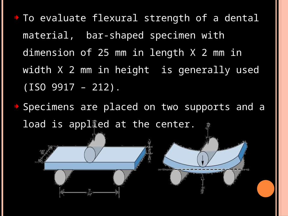
To evaluate flexural strength of a dental material,
bar-shaped specimen with dimension of 25 mm in
length X 2 mm in width X 2 mm in height is
generally used (ISO 9917 – 212).
Specimens are placed on two supports and a load
is applied at the center.

The load at yield is the sample specimen’s flexural
strength that is calculated by the following formula:
3Pl/2bd²
where,
P= the ultimate load at fracture,
l= the distance of the supports,
b= the width of the specimen,
d= the thickness of the specimen.
This test is also known as three-point bending test

It is the stress at which a material fractures.
IMPORTANT NOTE:
Ductile materials under tensile load, do not fracture
at the point at which maximum stress occurs but
fracture at a lower stress value.
FRACTURE STRENGTH
Ultimate strength
Fracture strength
Str
ess
Strain

Reason: After the maximum tensile force is applied, the
specimen begin to elongate excessively, resulting in
necking or a reduction of cross-sectional area.
In engineering stress strain graph, stress is calculated
from force and original cross sectional area and the
actual reduction in cross sectional area is not accounted.
Accordingly, the stress at the end of the curve is less
than at some intermediate point on the curve.
Therefore, in materials that exhibit necking, the ultimate
and fracture strengths are different.
For brittle material like ceramic, they are same points.

Str
ess
Strain
Stiff
Str
ess
Strain
Flexible
REVISION FOR PREDICTION OF PROPERTIES
FROM STRESS STRAIN CURVE
Predicting property - Elastic modulus
Depending on the inclination of the curve in elastic region.

Depending on the amount of plastic deformation
Str
ess
Strain
Ductile
Str
ess
Strain
Brittle
Predicting property – Plastic strain
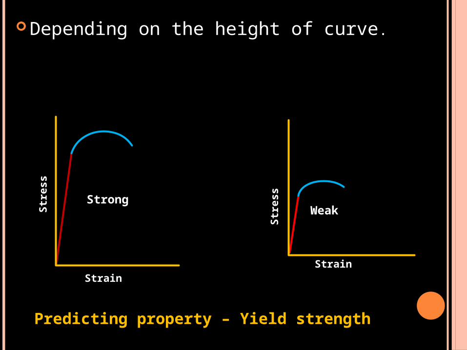
Depending on the height of curve. S
tress
StrainS
tress
Strain
Strong Weak
Predicting property – Yield strength

Stress values well below the ultimate tensile
strength can produce premature fracture of a
dental prosthesis or material because microscopic
flows grow slowly over many cycles of stress. This
phenomenon is called fatigue failure
Fatigue strength is the stress at which a material
fails under repeated loading.
Fatigue tests are performed by subjecting a
specimen to alternating stress applications below
the yield strength until fracture occurs.
FATIGUE STRENGTH
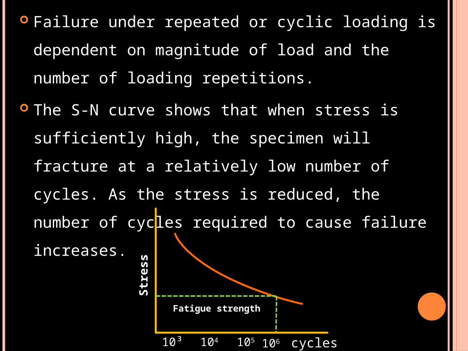
Failure under repeated or cyclic loading is
dependent on magnitude of load and the number
of loading repetitions.
The S-N curve shows that when stress is
sufficiently high, the specimen will fracture at a
relatively low number of cycles. As the stress is
reduced, the number of cycles required to cause
failure increases.
Fatigue strength
10³ 104 105 106 cycles
Str
ess
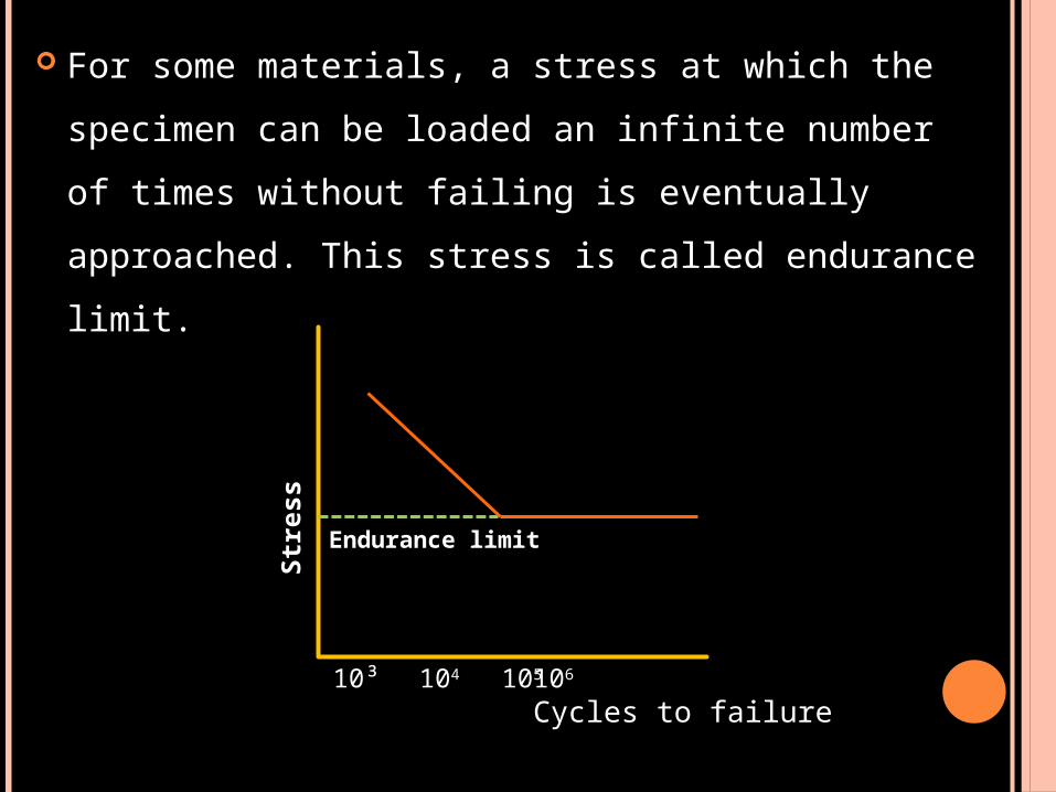
For some materials, a stress at which the specimen
can be loaded an infinite number of times without
failing is eventually approached. This stress is
called endurance limit.
Endurance limit
10³ 104 105 106 Cycles to failure
Str
ess

IMPORTANCE OF FATIGUE STRENGTH
Stress applications during mastication may
approach 3,00,000 flexures per year, whereas the
greater stress generated by removing and
inserting clasp retained RPD from the mouth
amounts to less than 1500 per year.
Restorations should be designed so the clinical
cyclic stresses are below the fatigue limit.
Phillips 11th edition.
Craig 12th edition.
Anderson’s applied dental materials 6th edition.
Introduction to dental materials. By Richard Van
Noort 6th edition.
A clinical guide to applied dental materials.
REFERENCES

THANK YOU