MECHANICAL ENGINEERING FORMULAE - Jeamar
10
Due to our policy of continuing development, all specifications are subject to change without notice. Users of these products are responsible for ensuring their suitability for the application in which they are being used. P: + 1 (877) 884-8118 E: [email protected] JEAMARWINCHES Power & Torque Imperial Standards Horsepower (HP) Common unit of mechanical power, one HP is the rate of work required to raise 33,000 pounds one foot in one minute. One Imperial Horsepower Equals: 33,000 foot pounds per minute 36 inch pounds torque at 1750 RPM .746 Kilowatts 1.014 Metric Horsepower (PS) 42.4 BTU per Minute Torque (T) Torque is a twisting force. Torque causes rotation of a shaft, or it will set up a twist in a stationary shaft. It is generally expressed in foot pounds or in inch pounds. Torque is measured by the load or pull and by the distance of the pull from the center of a shaft. Calculation Examples A cable wrapped around a 6” dia. drum must lift a 2500 pound weight. The drum rotates at 30 RPM. Metric (SI) Standards Power (P) The basic unit power measurement in the metric (SI) system is the Watt. 1000 Watts = 1 Kilowatt (kW) Torque (M) Torque is a twisting force. Torque causes rotation of a shaft, or it will set up a twist in a stationary shaft. It is generally expressed in Newton-Meters. SI Symbols M = Torque P = Power in Kilowatts N = Newton Kfgm = Kilogram force meter m = Meter N-m = Torque in Newton-Meters x = Multiplication Symbol Calculation Examples A cable wrapped around a .5 meter dia. drum must lift 5000 kilograms of weight. The drum rotates 50 RPM. MECHANICAL ENGINEERING FORMULAE Constant g = acceleration of free fall 9.81 m/s 2
Transcript of MECHANICAL ENGINEERING FORMULAE - Jeamar

Due to our policy of continuing development, all specifications are subject to change without notice. Users of these products are responsible for ensuring their suitability for the application in which they are being used.
P: + 1 (877) 884-8118 E: [email protected]
Power & Torque Imperial StandardsHorsepower (HP)
Common unit of mechanical power, one HP is the rate of work required to raise 33,000 pounds one foot in one minute.
One Imperial Horsepower Equals:33,000 foot pounds per minute36 inch pounds torque at 1750 RPM.746 Kilowatts1.014 Metric Horsepower (PS)42.4 BTU per Minute
Torque (T)Torque is a twisting force. Torque causes rotation of a shaft, or it will set up a twist in a stationary shaft. It is generally expressed in foot pounds or in inch pounds. Torque is measured by the load or pull and by the distance of the pull from the center of a shaft.
Calculation ExamplesA cable wrapped around a 6” dia. drum must lift a 2500 pound weight. The drum rotates at 30 RPM.
Metric (SI) StandardsPower (P)
The basic unit power measurement in the metric (SI) system is the Watt. 1000 Watts = 1 Kilowatt (kW)
Torque (M)Torque is a twisting force. Torque causes rotation of a shaft, or it will set up a twist in a stationary shaft. It is generally expressed in Newton-Meters.
SI SymbolsM = Torque P = Power in KilowattsN = Newton Kfgm = Kilogram force meterm = Meter N-m = Torque in Newton-Metersx = Multiplication Symbol
Calculation ExamplesA cable wrapped around a .5 meter dia. drum must lift 5000 kilograms of weight. The drum rotates 50 RPM.
MECHANICAL ENGINEERING FORMULAE
Constant g = acceleration of free fall 9.81 m/s2
Due to our policy of continuing development, all specifications are subject to change without notice. Users of these products are responsible for ensuring their suitability for the application in which they are being used.
P: + 1 (877) 884-8118 E: [email protected]
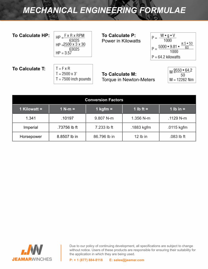
Conversion Factors
1 Kilowatt = 1 N-m = 1 kgfm = 1 lb ft = 1 lb in =
1.341 .10197 9.807 N-m 1.356 N-m .1129 N-m
Imperial .73756 lb ft 7.233 lb ft .1883 kgfm .0115 kgfm
Horsepower 8.8507 lb in 86.796 lb in 12 lb in .083 lb ft
MECHANICAL ENGINEERING FORMULAE
To Calculate HP:
To Calculate T:
To Calculate P:Power in Kilowatts
To Calculate M:Torque in Newton-Meters

Due to our policy of continuing development, all specifications are subject to change without notice. Users of these products are responsible for ensuring their suitability for the application in which they are being used.
P: + 1 (877) 884-8118 E: [email protected]
How To Calculate Line Parts
Number of Partsof Line
Ratio for BronzeBushed Sheaves
Ratio for Anti- Friction Bearing
Sheaves1 .96 .98
2 1.87 1.94
3 2.75 2.88
4 3.59 3.81
5 4.39 4.71
6 5.16 5.60
7 5.90 6.47
8 6.60 7.32
9 7.27 8.16
10 7.91 8.98
11 8.52 9.79
12 9.11 10.6
13 9.68 11.4
14 10.2 12.1
15 10.7 12.9
16 11.2 13.6
17 11.7 14.3
18 12.2 15.0
19 12.6 15.7
20 13.0 16.4
21 13.4 17.0
22 13.8 17.7
23 14.2 18.3
24 14.5 18.9
LIFTING WITH MULTI-PART LINE

Due to our policy of continuing development, all specifications are subject to change without notice. Users of these products are responsible for ensuring their suitability for the application in which they are being used.
P: + 1 (877) 884-8118 E: [email protected]
Winch SizingAs a General Guide to Sizing the Right Winch for the Job, the Following Detail May Be of Help:
LoadCalculate the total weight of all the loaded railcars to be moved simultaneously. For example, if four loaded railcars, each weighing 85 tons are to be moved together, the total load will be four times 85 tons, for a combined weight of 340 tons.
Rolling Resistance Under Ideal ConditionsResistance to rolling is influenced by the wheel journals, type of lubrication used and the ambient temperature. Assuming the railcars are to be moved along a straight, level and well-maintained track, select the running line pull for the lowest anticipated temperature, using Table 1.
Example: If the lowest anticipated temperature is 32°F, the required running line pull from Table 1 will be 15 lbs/ton. Multiply the total weight of the railcars 340 tons by 15 lbs/ton and the total running line pull becomes 5100 lbs.
Temperature More Than 32° F Less Than 32° F More Than 0° F Less Than -20° F
Running Line Pull (lbs/ton) 12 15 20 25
Track GradientFor each one percent gradient a rise of one foot for every 100 feet of track the running line pull must be increased by 20 lbs/ton.
Example: If the track has a 1.5% grade, the additional running line pull is 20, multiplied by 1.5, or 30 lbs/ton. The new running line pull is the original 15 lbs/ton plus the 30 lbs/ton adjustment for grade or 45 lbs/ton. The new running line pull is now calculated by multiplying 45 lbs/ton by the 350 tons of railcars for a total of 15,300 lbs.
Track CurvatureTo overcome the effects of wheels binding against rails on curved sections of track, running line pull must be increased.
Track curvature is expressed in terms of radius or degree of curvature. When this information is not available, the chordal factor can be easily measured. Simply stretch a 50-foot tape along the inside of the curve and measure the distance 'A' in Diagram 1.
RAILCAR PULLING DETAIL

Due to our policy of continuing development, all specifications are subject to change without notice. Users of these products are responsible for ensuring their suitability for the application in which they are being used.
P: + 1 (877) 884-8118 E: [email protected]
Example: Chordal factor A was found to be 6.5 inches. The additional running line pull from Table 2 is 7.50 lbs/ton. Now the running line pull has increased from 45 lbs/ton to 52.5 lbs/ton. Again, multiplied by the 340 tons of railcars, the total running line pull is 17,850 lbs.
Track ConditionsIf track conditions are substandard soft ballast, uneven or deteriorating ties or debris on the track additional running line pull will be needed. Since the condition of substandard track can vary considerably, Jeamar recommends that line pull be measured with a dynamometer.
Radius (ft)
Degree of Curvature (degree)
Chordal Factor A (in)
Additional Running Line Pull (lbs/ton)
1146 5 3.50 3.75
573 10 6.50 7.50
383 15 9.75 11.25
288 20 13.00 15.00
231 25 16.50 18.75
193 30 20.00 22.50
166 35 23/50 26.25
146 40 27.00 30.00
Select the appropriate additional running line pull from Table 2 using either radius, degrees of curvature or chordal factor. (Interpolation for a measure of curvature is not shown.)
RAILCAR PULLING DETAIL

Due to our policy of continuing development, all specifications are subject to change without notice. Users of these products are responsible for ensuring their suitability for the application in which they are being used.
P: + 1 (877) 884-8118 E: [email protected]
Determining The Stress On A HookMultiply the Pull on the Lead Line By a Suitable Factor From the Following Table. All Loads Shown Ignore Frictional Losses in the System.
Angle Factor0° 2.005° 1.998
10° 1.9915° 1.9820° 1.9725° 1.9530° 1.9335° 1.9040° 1.8745° 1.8450° 1.8155° 1.7760° 1.7365° 1.6970° 1.6475° 1.5880° 1.5385° 1.4790° 1.4195° 1.35
100° 1.29105° 1.22110° 1.15115° 1.07120° 1.00125° 0.92130° 0.84135° 0.76140° 0.68145° 0.60150° 0.52155° 0.43160° 0.35165° 0.26170° 0.17175° 0.08180° 0.00
LOADS ON SHEAVES & BLOCKS
The stress on a sheave or block varies with the degree of angle between the lead and load lines. When the two lines are parallel, 1000 pounds on the lead line results in a load of 2000 pounds on the hook. As the angle between the lines increases, the stress on the hook is reduced as illustrated below.

Due to our policy of continuing development, all specifications are subject to change without notice. Users of these products are responsible for ensuring their suitability for the application in which they are being used.
P: + 1 (877) 884-8118 E: [email protected]
Note:Note: Since the rope is continuous, from the winch drum to the attachment point, the load is always 1 ton, no matter where measured. The head load is the number of line attachments at the head sheave x 1 ton. All loads shown ignore frictional losses in the system.
CALCULATING HEAD LOADS

Due to our policy of continuing development, all specifications are subject to change without notice. Users of these products are responsible for ensuring their suitability for the application in which they are being used.
P: + 1 (877) 884-8118 E: [email protected]
CALCULATING FLEET ANGLE

Due to our policy of continuing development, all specifications are subject to change without notice. Users of these products are responsible for ensuring their suitability for the application in which they are being used.
P: + 1 (877) 884-8118 E: [email protected]
Wire Rope Specifications Grades - Slope & Grade Resistance
REFERENCE CHARTS
Preformed Galvanized Aircraft Cable 7x19
Size Diameter (in)
Weight per 100’ (lbs)
Breaking Strength (lbs)
1/8” 2.9 lbs. 2,000 lbs.
3/16” 6.5 lbs. 4,200 lbs.
1/4” 11.0 lbs. 7,000 lbs.
5/16” 17.3 lbs. 9,800 lbs.
3/8” 24.3 lbs. 14,400 lbs.
Grade (% per 100 Horizontal ft)
Slope (Degrees & Minutes
per 100 Horizontal ft
Grade Resistance (lbs. Pull per
Ton to Overcome Grade Resistance)
1 0-34 202 1-9 403 1-43 604 2-17 805 2-52 1006 3-26 1207 4-0 1408 4-34 1609 5-9 180
10 5-43 19911 6-17 21912 6-51 23813 7-24 25814 7-58 27715 8-32 29616 9-39 31517 9-5 33418 10-12 35319 10-45 37320 11-19 39225 14-2 48530 15-17 57535 16-42 66040 21-48 74345 24-14 82250 26-34 89555 28-49 96560 30-58 102565 33-1 108570 34-59 114575 36-52 119680 38-40 124885 40-22 129590 41-59 133895 43-32 1376
100 45-0 1402
Steel I.W.R.C. 6x37
Size Diameter (in)
Weight per 100’ (lbs)
Breaking Strength (lbs)
7/16” 33 lbs. 20,400 lbs.
1/2” 43 lbs. 26,600 lbs
9/16” 54 lbs. 33,600 lbs.
5/8” 67 lbs. 41,200 lbs.
3/4” 96 lbs. 58,800 lbs.
7/8” 131 lbs. 79,600 lbs.
1” 170 lbs. 103,400 lbs.
1-1/8” 216 lbs. 130,000 lbs.
1-1/4” 266 lbs. 159,800 lbs.
1-3/8” 322 lbs. 192,000 lbs.
1-1/2” 384 lbs. 228,000 lbs
1-5/8” 450 lbs. 264,000 lbs.
1-3/4” 522 lbs. 306,000 lbs.
1-7/8” 600 lbs. 384,000 lbs.
2” 682 lbs. 396,000 lbs.

Due to our policy of continuing development, all specifications are subject to change without notice. Users of these products are responsible for ensuring their suitability for the application in which they are being used.
P: + 1 (877) 884-8118 E: [email protected]
Equivalent of Common Fractions of an Inch
DECIMAL & METRIC