MECHANICAL ENGINEERING Fluids of Mechanics Hydraulic ...smec.ac.in/sites/default/files/lab1/Fluid...
156
MECHANICAL ENGINEERING Fluids of Mechanics & Hydraulic Machines Lab Manual EXPERIMENT-1 IMPACT OF JETS ON VANES 1.1OBJECTIVE: To find the coefficient of impact of jet on a flat circular and hemispherical vane. 1.2RESOURCES: S.NO Name of the equipment QTY 1 Impact of jet apparatus 2 Stop watch. 3 4 1.3 PRECAUTIONS: 1. Water flow should be steady and uniform 2. The reading on the scale should be taken without anerror 3. The weight should be put slowly & one by one. 4. After changing the vane the flask should be closed tightly 1.4: Graph: Draw the graph F a vs V 2 . From this compute the value of the co-efficient of impact MODEL GRAPH V 2 F a 1.5 Procedure: 1) Fix the required diameter jet, and the vane of required shape in position and zero the force indicator 2) Keep the delivery valve closed and switch on the pump 3) Close the front transparent cover tightly 4) Open the delivery valve and adjust the flow rate of water as read on the Rota meter 5) Observe the force as indicated on force indicator 6) Note down the diameter of the jet, shape of vane, flow rate and force and tabulate the results 7) Switch off the pump after the experiment is over and close the delivery valve.
Transcript of MECHANICAL ENGINEERING Fluids of Mechanics Hydraulic ...smec.ac.in/sites/default/files/lab1/Fluid...
MECHANICAL ENGINEERING
Fluids of Mechanics & Hydraulic Machines Lab Manual
EXPERIMENT-1 IMPACT OF JETS ON VANES 1.1OBJECTIVE: To find the coefficient of impact of jet on a flat circular and hemispherical vane.
1.2RESOURCES:
S.NO Name of the equipment QTY
1 Impact of jet apparatus
2 Stop watch.
3
4
1.3 PRECAUTIONS:
1. Water flow should be steady and uniform
2. The reading on the scale should be taken without anerror
3. The weight should be put slowly & one by one.
4. After changing the vane the flask should be closed tightly
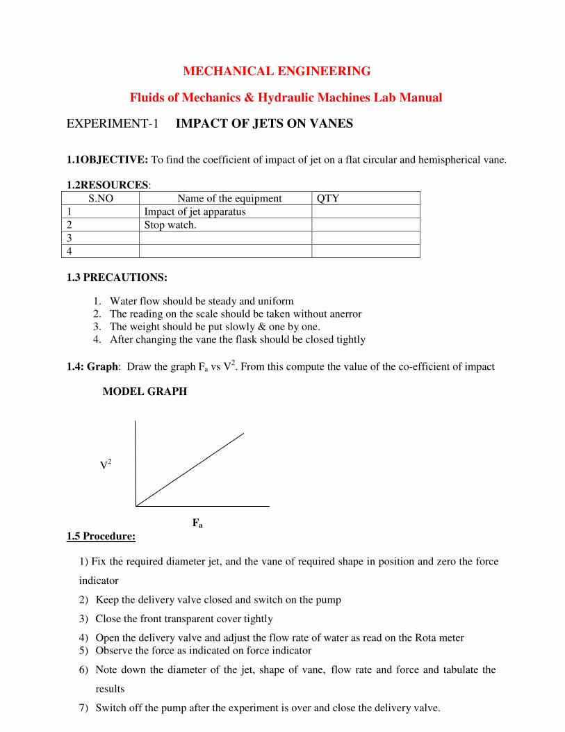
1.4: Graph: Draw the graph Fa vs V2. From this compute the value of the co-efficient of impact
MODEL GRAPH
V2
Fa
1.5 Procedure:
1) Fix the required diameter jet, and the vane of required shape in position and zero the force
indicator
2) Keep the delivery valve closed and switch on the pump
3) Close the front transparent cover tightly
4) Open the delivery valve and adjust the flow rate of water as read on the Rota meter
5) Observe the force as indicated on force indicator
6) Note down the diameter of the jet, shape of vane, flow rate and force and tabulate the
results
7) Switch off the pump after the experiment is over and close the delivery valve.
1.6 Theory:
A jet of water issuing from a nozzle has some velocity and hence it possesses a certain
amount of kinetic energy. If this jet strikes an obstruction (plate) plated in its path, it will exert a
force on the obstruction. This impressed force is known as impact of the jet and it is designated
as hydrodynamic force. This force is due to the change in the momentum of the jet as a
consequence of the impact. This force is equal to the rate of change of momentum i.e.; the force
is equal to (mass striking the plate per second) x (change in velocity)
The amount of force exerted depends on the diameter of jet, shape of vane, fluid density,
and flow rate of water. More importantly, it also depends on whether the vane is moving or
stationary. In our case, we are concerned about the force exerted on the stationary vanes.
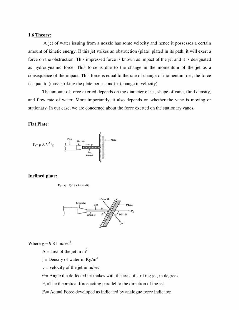
Flat Plate:
Inclined plate:
Where g = 9.81 m/sec2
A = area of the jet in m2
∫ = Density of water in Kg/m3
v = velocity of the jet in m/sec
Ө= Angle the deflected jet makes with the axis of striking jet, in degrees
Ft =The theoretical force acting parallel to the direction of the jet
Fa= Actual Force developed as indicated by analogue force indicator
1.7 Description:
It is a closed circuit water re- circulation system consisting of sump tank, mono block
centrifugal pump set, jet/vane chamber, Rota meter for flow rate measurement, direct reading
analog force indicator. The water is drawn from the sump tank by mono block centrifugal pump
and delivers it vertically to the nozzle through rotameter. The rotameter is a direct indicating
flow rate instrument which gives the discharge in litters per minute (LPM) which is determined
by the top position of the float. The flow control valve is also provided for controlling the water
into the nozzle. The water is issued out of nozzle as jet. The jet is made to strike the vane, the
force of which is transferred directly to the force indicator. The force is read in Kgf or N. The
provision is made to change the size of nozzle / jet and the vane of different shapes.
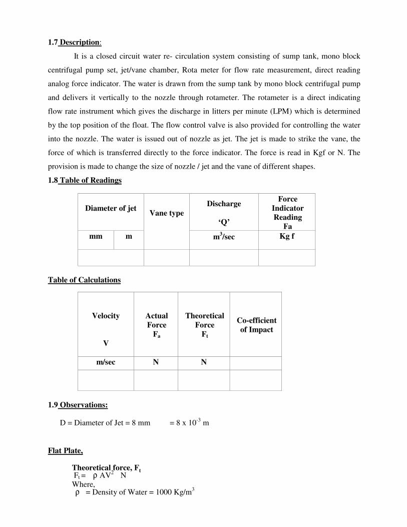
1.8 Table of Readings
Diameter of jet
Vane type
Discharge
‘Q’
Force
Indicator
Reading
Fa
mm
m
m
3/sec
Kg f
Table of Calculations
Velocity
V
Actual
Force
Fa
Theoretical
Force
Ft
Co-efficient
of Impact
m/sec
N
N
1.9 Observations:
D = Diameter of Jet = 8 mm = 8 x 10⁻³
m
Flat Plate,
Theoretical force, F Ft = ρ AV
2 N
Where, ρ = Density of Water = 1000 Kg/m
3
t
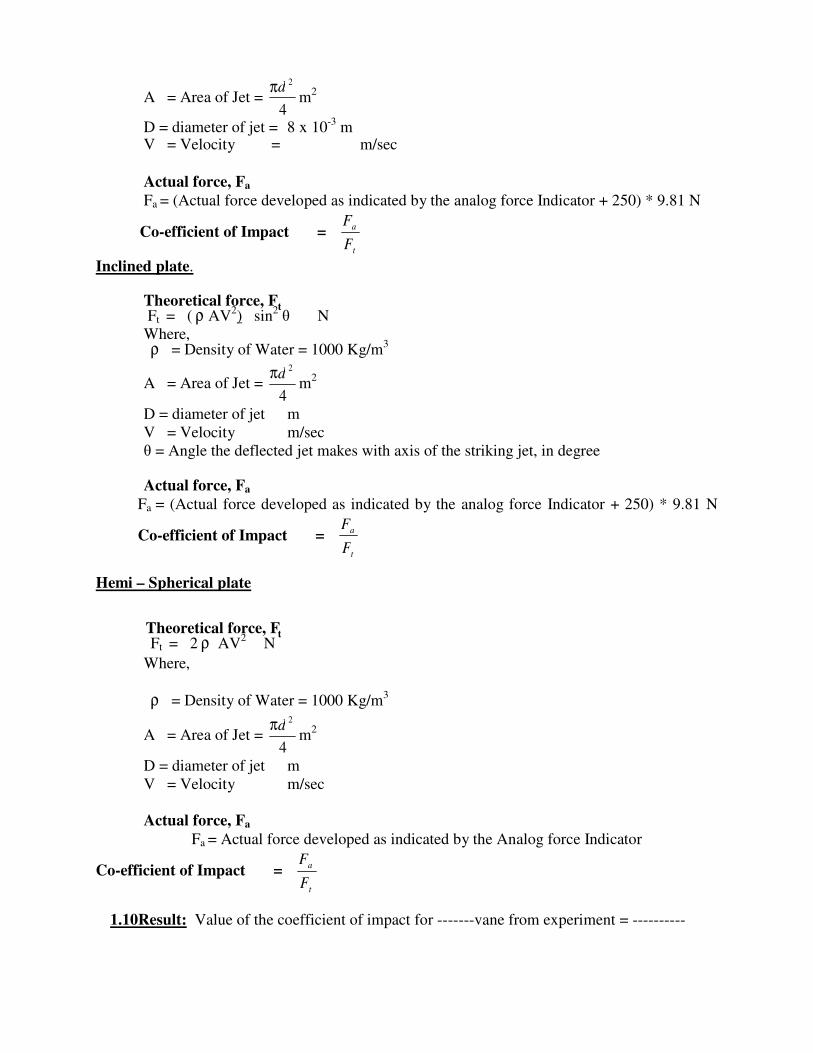
A = Area of Jet = π
4
2
m2
D = diameter of jet = 8 x 10⁻³
m V = Velocity = m/sec
Actual force, Fa
Fa = (Actual force developed as indicated by the analog force Indicator + 250) * 9.81 N
Co-efficient of Impact = Fa
t
Inclined plate.
Theoretical force, F Ft = ( ρ AV
2) sin
2 θ N
Where, ρ = Density of Water = 1000 Kg/m
3
A = Area of Jet = π
4
2
m2
D = diameter of jet m
V = Velocity m/sec
θ = Angle the deflected jet makes with axis of the striking jet, in degree Actual force, Fa
Fa = (Actual force developed as indicated by the analog force Indicator + 250) * 9.81 N
Co-efficient of Impact = Fa
t
Hemi – Spherical plate
Theoretical force, F Ft = 2 ρ AV
2 N
Where,
ρ = Density of Water = 1000 Kg/m3
A = Area of Jet = π
4
2
m2
D = diameter of jet m
V = Velocity m/sec
Actual force, Fa
Fa = Actual force developed as indicated by the Analog force Indicator
Co-efficient of Impact = Fa
t
1.10Result: Value of the coefficient of impact for -------vane from experiment = ----------
d
F
t
d
F
t
d
F
1.11Viva Questions:
1. Define the term Impact of Jet?
Ans. The liquid comes out in the form of a jet from the outlet of a nozzle, which is fitted
to a pipe through which the liquid is flowing under pressure. If some plate, which may be
fixed or moving, is placed in the path of the jet, a force.
2. Write the formula for force exerted by a jet of water on a stationary & moving
plate? Ans. Fx= ρaV2
---- for a stationary vertical plate
=ρaV2
sin θ--- for an inclined stationary plate
= ρa (V-u)2
---- for a moving vertical plate
=ρa(V-u)2
sin2θ--- for an inclined moving
plate Where V=Velocity of the jet
u= Velocity of the plate in the direction of
jet a =Area of cross section of the jet θ =Angle between the jet & the plate for inclined plate
3. Write the formula for force exerted by a jet of water on a curved plate at center & at one
of the tips of the jet?
Ans. Fx=ρaV2
(1+cosθ) ---- for curved plate & jet strikes at the centre
=ρaV2
(1+cosθ) ---- for curved plate & jet strikes at one of the tips of the
jet Where V=Velocity of the jet
a =Area of cross section of the jet
θ =Angle between the jet & the plate for inclined plate
4. What is an impulse momentum equation?
Ans. The liquid comes out in the form of a jet from the outlet of a nozzle, which is fitted
to a pipe through which the liquid is flowing under pressure. If some plate, which may be
fixed or moving, is placed in the path of the jet, a force is exerted by the jet on the plate.
This force is obtained from Newton’s second law of motion or from impulse-momentum
equation.
1.11LAB ASSIGNMENT:
1. Define the terms momentum, moment & impulse?
Ans. When a force (Push or pull) is applied on the bodies it tries to change the state of
rest or state of motion of those bodies. The amount of force applied is equal to the
rate of change of momentum, where momentum is the product of mass and velocity
2. Explain the term dynamic machines.
Ans. Dynamic machines: The term dynamic means power. Dynamic machines meaning
power machine, which receives the energy from the flowing fluid in the form of momentum
and coverts the change in momentum into useful work.
3. What is an impulse turbine?
Ans. In impulse turbine a high velocity jet issued. From nozzle strikes a series of suitably
shaped buckets fixed on the periphery of a wheel. The wheel get resulting momentum and it
gets rotated and thus we get the mechanical energy from the turbine.
EXPERIMENT-2 PERFORMANCE TEST ON PELTON WHEEL TURBINE
2.1OBJECTIVE: To conduct performance test on the given Pelton wheel turbine
2.2RESOURCES:
S.NO Name of the Equipment Qty
1 A Pelton Turbine
2 A Supply pump unit to
supply water
3 Flow Measuring unit
consisting of a Venturimeter
and Pressure Gauges
4 Piping system
5 Sump
2.3 Precautions:
1) After taking one set of reading release the tension of the belt and run the turbine at no
load condition for at least five minutes.
2) By pass valve should always fully open at the time of starting the
pump. 3) Before starting the pump check the manometer tapings.
4) Tachometer should not touch with any moving part at the time of r.p.m.
measurement. 5) After experiment drain off the water from the tank
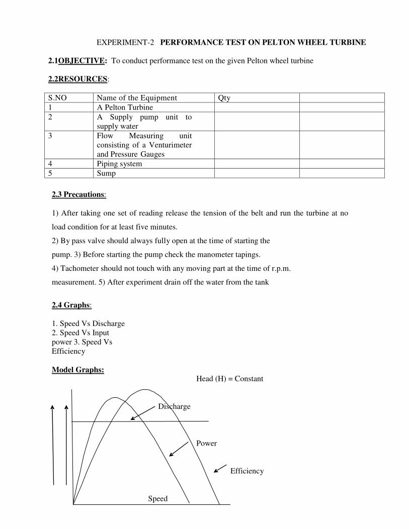
2.4 Graphs:
1. Speed Vs Discharge
2. Speed Vs Input
power 3. Speed Vs
Efficiency
Model Graphs: Head (H) = Constant
Discharge
Power
Efficiency
Speed
2.5 Procedure:
1) Connect the supply water pump-water unit to 3 ph, 440V, 30A, electrical supply, with
neutral and earth connections and ensure the correct direction of the pump motor unit.
2) Keep the Gate Valve and Sphere valve closed.
3) Keep the Brake Drum loading at zero
4) Press the green button of the supply pump starter. Now the pump picks- up the full speed
and becomes operational.
5) Slowly open the Sphere Valve so that the turbine rotor picks the speed and
conduct Experiment on constant speed.
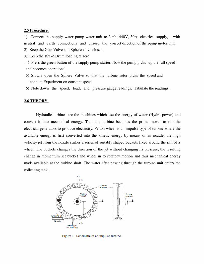
6) Note down the speed, load, and pressure gauge readings. Tabulate the readings. 2.6 THEORY:
Hydraulic turbines are the machines which use the energy of water (Hydro power) and
convert it into mechanical energy. Thus the turbine becomes the prime mover to run the
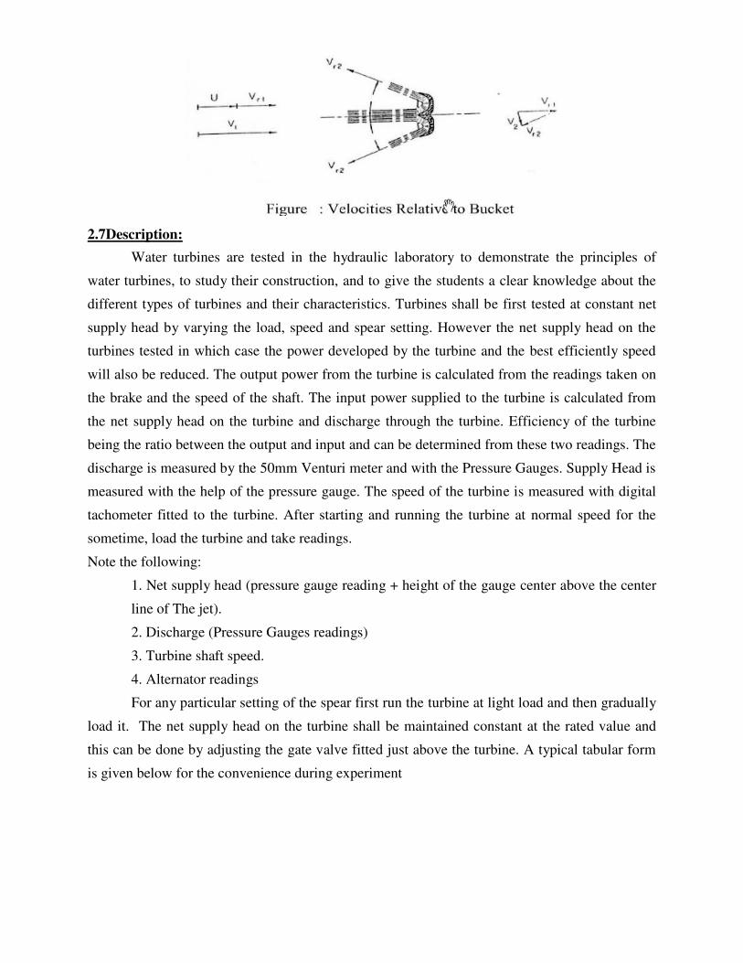
electrical generators to produce electricity. Pelton wheel is an impulse type of turbine where the
available energy is first converted into the kinetic energy by means of an nozzle, the high
velocity jet from the nozzle strikes a series of suitably shaped buckets fixed around the rim of a
wheel. The buckets changes the direction of the jet without changing its pressure, the resulting
change in momentum set bucket and wheel in to rotatory motion and thus mechanical energy
made available at the turbine shaft. The water after passing through the turbine unit enters the
collecting tank.
2.7Description:
Water turbines are tested in the hydraulic laboratory to demonstrate the principles of
water turbines, to study their construction, and to give the students a clear knowledge about the
different types of turbines and their characteristics. Turbines shall be first tested at constant net
supply head by varying the load, speed and spear setting. However the net supply head on the
turbines tested in which case the power developed by the turbine and the best efficiently speed
will also be reduced. The output power from the turbine is calculated from the readings taken on
the brake and the speed of the shaft. The input power supplied to the turbine is calculated from
the net supply head on the turbine and discharge through the turbine. Efficiency of the turbine
being the ratio between the output and input and can be determined from these two readings. The
discharge is measured by the 50mm Venturi meter and with the Pressure Gauges. Supply Head is
measured with the help of the pressure gauge. The speed of the turbine is measured with digital
tachometer fitted to the turbine. After starting and running the turbine at normal speed for the
sometime, load the turbine and take readings.
Note the following:
1. Net supply head (pressure gauge reading + height of the gauge center above the center
line of The jet).
2. Discharge (Pressure Gauges readings)
3. Turbine shaft speed.
4. Alternator readings
For any particular setting of the spear first run the turbine at light load and then gradually
load it. The net supply head on the turbine shall be maintained constant at the rated value and
this can be done by adjusting the gate valve fitted just above the turbine. A typical tabular form
is given below for the convenience during experiment
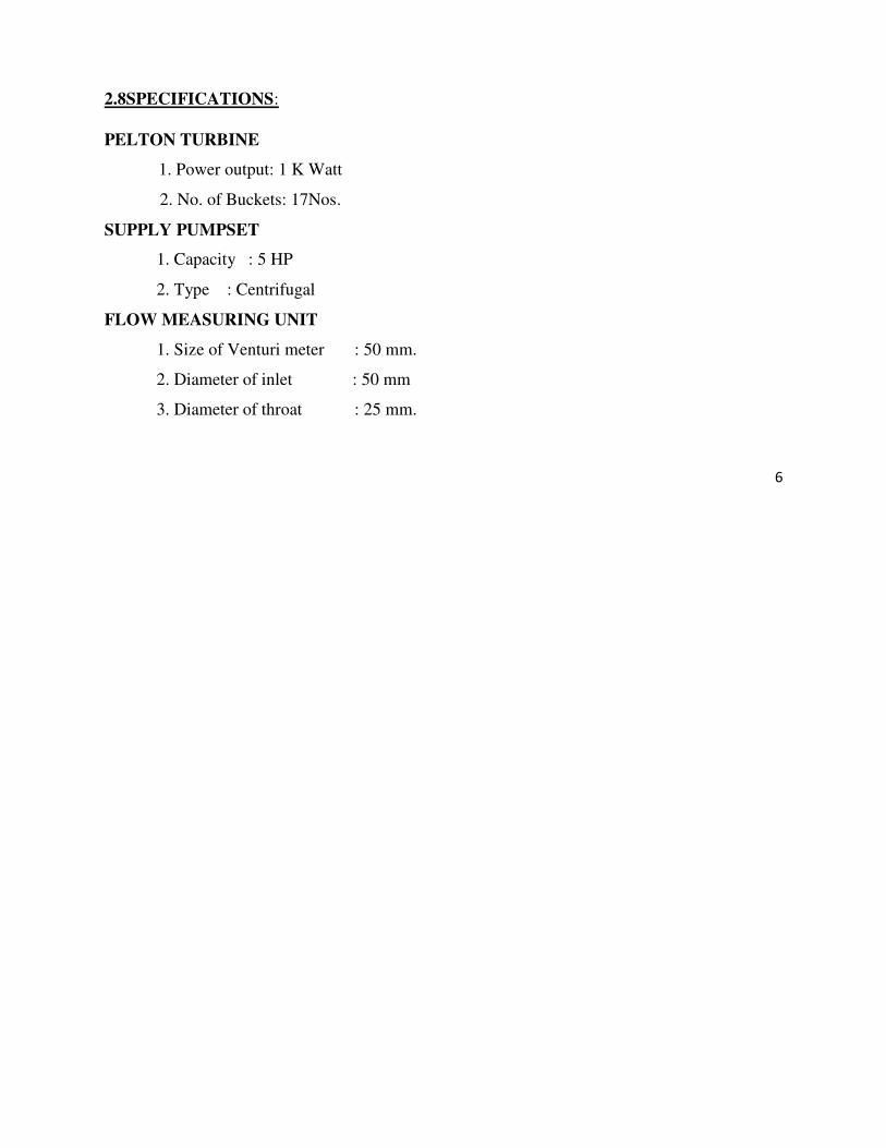
2.8SPECIFICATIONS:
PELTON TURBINE
1. Power output: 1 K Watt
2. No. of Buckets: 17Nos.
SUPPLY PUMPSET
1. Capacity : 5 HP
2. Type : Centrifugal
FLOW MEASURING UNIT
1. Size of Venturi meter : 50 mm.
2. Diameter of inlet : 50 mm
3. Diameter of throat : 25 mm.
6

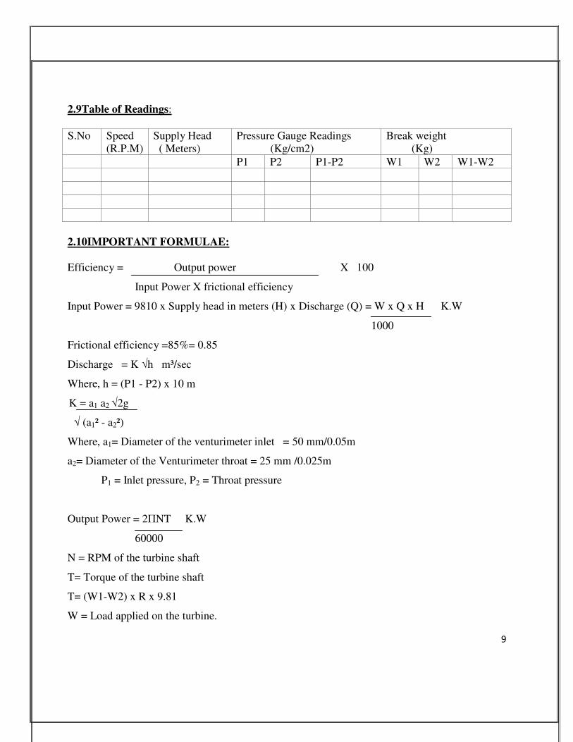
2.9Table of Readings:
S.No
Speed
(R.P.M)
Supply Head
( Meters)
Pressure Gauge Readings
(Kg/cm2)
Break weight
(Kg)
P1 P2 P1-P2 W1 W2 W1-W2
2.10IMPORTANT FORMULAE:
Efficiency = Output power X 100
Input Power X frictional efficiency
Input Power = 9810 x Supply head in meters (H) x Discharge (Q) = W x Q x H K.W
1000
Frictional efficiency =85%= 0.85
Discharge = K √h m³/sec
Where, h = (P1 - P2) x 10 m
K = a1 a2 √2g
√ (a1² - a2²)
Where, a1= Diameter of the venturimeter inlet = 50 mm/0.05m
a2= Diameter of the Venturimeter throat = 25 mm /0.025m
P1 = Inlet pressure, P2 = Throat pressure
Output Power = 2ΠNT K.W
60000
N = RPM of the turbine shaft
T= Torque of the turbine shaft
T= (W1-W2) x R x 9.81
W = Load applied on the turbine.
9
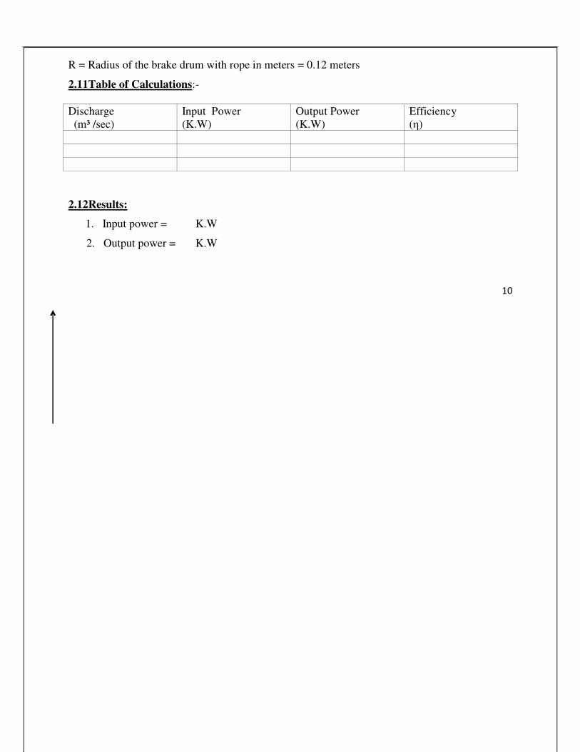
R = Radius of the brake drum with rope in meters = 0.12 meters
2.11Table of Calculations:-
Discharge
(m³ /sec)
Input Power
(K.W)
Output Power
(K.W)
Efficiency
(η)
2.12Results:
1. Input power = K.W
2. Output power = K.W
10
3. Efficiency =
2.13Viva Voce Questions: -
1. What is the basic difference between an impulse & reaction turbine?
Ans. If at the inlet of the turbine, the energy available is only kinetic energy, the turbine is
known as impulse turbine. If at the inlet of the turbine, the water possesses kinetic energy as
well as pressure energy, the turbine is known as reaction turbine
2. What is the basic difference between a tangential flow & radial flow turbine?
Ans. If the water flows along the tangent of the runner, the turbine is known at tangential flow
turbine. If the water flows in the radial direction through the runner, the turbine is called radial
flow turbine
3. What is basic difference between axial flow & mixed flow turbine?
Ans. If the water flows through the runner along the direction parallel to the axis of the runner,
the turbine is called axial flow turbine. If the water flows through the runner in the radial
direction but leaves in the direction parallel to the axis of rotation of the runner, the turbine is
called mixed flow turbine
4. What do you mean specific speed of a turbine?
Ans. It is defined as the speed of a turbine which is identical in shape, geometrical dimensions,
blade angles, gate opening etc., with the actual turbine but of such a size that it will develop
unit power when working under unit head. (Ns)
5. Define unit speed, unit power & unit discharge?
Ans. Unit speed is defined as the speed of a turbine working under a unit head
(i.e., under a head of 1m). (Nu)
o Unit discharge is defined as the discharge passing through a turbine, which is working
under unit head (Qu)
o Unit power is defined as the power developed by a turbine, working under a unit head
(Pu)
6. Define hydraulic machines?
Ans. Hydraulic machines are defined as those machines which convert either hydraulic
energy (energy possessed by water) into mechanical (which is further converted into
electrical energy) or mechanical energy into hydraulic energy.
11
7. Define turbines?
Ans. The hydraulic machines, which convert the hydraulic energy into mechanical
energy, are called turbine.
8. The study of hydraulic machines consists of what?
Ans. It consists of study of turbines and pumps.
9. Define the term Gross head.
Ans. The Gross head or Total head is the difference between the water level at the reservoir
(also known as head race) and the level at the tail race. (Hg)
10. Define net head?
Ans. It is also called effective head and is defined as the head available at the inlet of
the turbine. H=Hg-hf.
11. Define Hydraulic efficiency?
Ans. It is defined as the ratio of power given by water to the runner of a turbine to the
power supplied by the water at the inlet of the turbine.
12. Define Mechanical efficiency?
Ans. It is defined as the ratio of power available at the shaft of the turbine to the power
delivered to the runner.
13. Define Volumetric efficiency?
Ans. It is defined as the ratio of the volume of the water actually striking the runner to
the volume of water supplied to the turbine.
14. Define Overall efficiency?
Ans. It is defined as the ratio of power available at the shaft of the turbine to the power
supplied by the water at the inlet of the turbine.
15. The pelton wheel (or) pelton turbine is ---- a tangential flow impulse turbine
16. Write the classification of hydraulic turbines according to the type of energy at inlet?
Ans. i) impulse turbine, and ii) reaction turbine
17. Write the classification of hydraulic turbines according to the direction of flow through
runner?
Ans. i) tangential flow turbine, ii) radial flow turbine, iii) axial flow turbine, and iv)
mixed flow turbine.
18. Write the classification of hydraulic turbines according to the head at the inlet of turbine?
Ans. i) high head turbine, ii) medium head turbine, and iii) low head turbine.
19. Write the classification of hydraulic turbines according to the specific speed of the turbine?
Ans. i) low specific speed turbine, ii) medium specific speed turbine, and iii) high specific
speed turbine,
20. Why the draft tube is not used for Pelton turbine?

12
Ans. In case of pelton turbine all the K. E. is lost and draft tube is not used because the
pressure value is just the atmospheric so there is no requirement of draft tube.
21. What is the function of the casting?
Ans. The function of the casting is to prevent the splashing of the water & to discharge
water to tail race. It also acts as a safeguard against accidents.
EXPERIMENT-3
PERFORMANCE TEST ON FRANCIS TURBINE
3.1 OBJECTIVE: To conduct performance test on the given
Francis turbine
3.2 RESOURCES:
S.NO Name of the equipment QTY
1 Francis turbine experiment setup
2 Stop watch.
3
4
3.3THEORY:
The model Francis Turbine is an inward mixed flow reaction turbine i.e. the water under
pressure enters the runner from the guide vanes towards the center in radial direction and
discharge out of the runner axially. The Francis Turbine operates under medium head and also
requires medium quality of water. A part of the head acting on the turbine is transformed into
kinetic energy and rest remains as pressure head. There is a difference of pressure between the
guide vanes and the runner, which is called the reaction pressure and is responsible for the
motion of the runner. That is why a Francis Turbine is also known as reaction turbine. In this
turbine the pressure at the inlet is more then that at the outlet. This means that the water in the
turbine must flow in a closed conduit, unlike the Pelton type where the water strikes only a few
of the runner buckets at a time. In the Francis turbine the runner is always full of water. The
movement of runner is affected by the change of both the Kinetic and potential energies of water.
After doing work the water is discharged to the tailrace through a closed tube of gradually
enlarging section. This tube is known as draft tube. The free end of the draft tube is submerged
deep in the tailrace water. Thus the entire water passage, right from the headrace up to the
tailrace, totally enclosed.
3.4Experimental setup:
The turbine is placed on a substantial concreted base. The supply pump set draws water
from the main tank and supplies it to turbine. A venturimeter is mounted to measure the flow. A
13
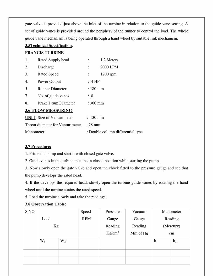
gate valve is provided just above the inlet of the turbine in relation to the guide vane setting. A
set of guide vanes is provided around the periphery of the runner to control the load. The whole
guide vane mechanism is being operated through a hand wheel by suitable link mechanism.
3.5Technical Specification:
FRANCIS TURBINE
1. Rated Supply head
2. Discharge
3. Rated Speed
: 1.2 Meters
: 2000 LPM
: 1200 rpm
4. Power Output : 4 HP
5. Runner Diameter : 180 mm
7. No. of guide vanes : 8
8. Brake Drum Diameter : 300 mm
3.6 FLOW MEASURING
UNIT: Size of Venturimeter
Throat diameter for Venturimeter
Manometer
: 130 mm
: 78 mm
: Double column differential type
3.7 Procedure:
1. Prime the pump and start it with closed gate valve.
2. Guide vanes in the turbine must be in closed position while starting the pump.
3. Now slowly open the gate valve and open the chock fitted to the pressure gauge and see that
the pump develops the rated head.
4. If the develops the required head, slowly open the turbine guide vanes by rotating the hand
wheel until the turbine attains the rated speed.
5. Load the turbine slowly and take the readings.
3.8 Observation Table:
S.NO
Load
Kg
Speed
RPM
Pressure
Gauge
Reading
Kg/cm2
Vacuum
Gauge
Reading
Mm of Hg
Manometer
Reading
(Mercury)
cm
W1
W2
h1
h2

14
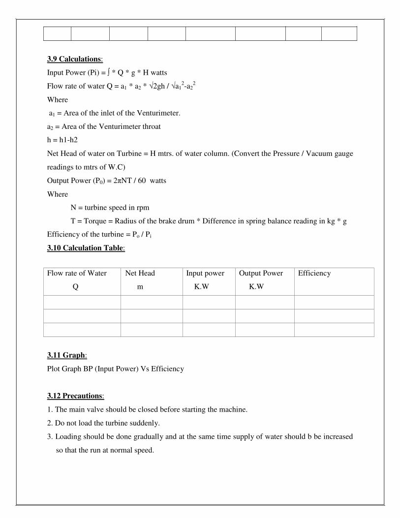
3.9 Calculations:
Input Power (Pi) = ∫ * Q * g * H watts
Flow rate of water Q = a1 * a2 * √2gh / √a12-a2
2
Where
a1 = Area of the inlet of the Venturimeter.
a2 = Area of the Venturimeter throat
h = h1-h2
Net Head of water on Turbine = H mtrs. of water column. (Convert the Pressure / Vacuum gauge
readings to mtrs of W.C)
Output Power (P0) = 2πNT / 60 watts
Where
N = turbine speed in rpm
T = Torque = Radius of the brake drum * Difference in spring balance reading in kg * g
Efficiency of the turbine = Po / Pi
3.10 Calculation Table:
Flow rate of Water
Q
Net Head
m
Input power
K.W
Output Power
K.W
Efficiency
3.11 Graph:
Plot Graph BP (Input Power) Vs Efficiency
3.12 Precautions:
1. The main valve should be closed before starting the machine.
2. Do not load the turbine suddenly.
3. Loading should be done gradually and at the same time supply of water should b be increased
so that the run at normal speed.

15
3.13Viva Voce Questions: -
1 What means reaction turbine?
Ans. It means that the water at the inlet of the turbine possesses kinetic energy as well as
pressure energy. As the water flows through the runner, a part of pressure energy goes on
changing into kinetic energy.
2 What is the function of draft tube in a reaction turbine?
Ans. The pressure at the exit of the runner of a reaction turbine is generally less than
atmospheric pressure. The water exit cannot be directly discharge to the tail race. A tube or
pipe of gradually increasing area is used for discharging water from the exit of the turbine to
the tail race. This tube increasing area is called draft tube.
3 Define specific speed of a turbine?
Ans. It is defined as the speed of a turbine which is identical in shape, geometric dimensions,
blade angles, gate opening etc., with the actual turbine but of such a size that it will develop
unit power when working under unit head. (Ns). It is used in comparing the different types of
turbines as every type of turbine has different specific speed.
4 List the various functions of surge tanks.
Ans. Surge tanks have the following functions:
1. To control the pressure variations, due to rapid changes in the pipeline flow, thus
eliminating water hammer possibilities.
2. To regulate the flow of water to the turbines.
3. To reduce the distance between the free water surface and turbine, thereby reducing the
water hammer effect on penstock.
4. It protects up stream tuner from high pressure rises.
5 Define degree of reaction and Euler’s Head.
Ans. The degree of reaction (R) is defined as a ratio of change of pressure energy in the runner
to the change of total energy in the runner per kg of water.
Euler’s Head: It is defined as energy transfer per unit weight.
6 Define governing of turbine?
16
Ans. It is defined as the operation by which the speed of the turbine is kept constant under all
conditions of working. It is done automatically by means of a governor, which regulates the
rate of flow through the turbines according to the changing load condition on the turbine.
,
EXPERIMENT-4
KAPLAN TURBINE
4.1 OBJECTIVE: To study the characteristic curves of a Kaplan turbine at constant head condition.
4.2 RESOURCES:
S.NO Name of the equipment QTY
1 stop clock
2 meter scale
3 Kaplan turbine setup
4 3-phase power supply.
4.3 Theory: Kaplan turbine is a reaction turbine operated at low head. It consists of guide
vanes, runner, scroll casing and draft tube at the exit. Water turns through right angles and
guided through the wing graphs runner and 'thus rotating the runner shaft. The runner has
four blades, which can be turned about their own axis so that the angle of inclination may
be adjusted while the turbine is in operation. By varying the guide vane angles, high
efficiency can be maintained over a wide range of operating conditions. After passing
through the turbine, water enters into the collecting tank through draft tube. Loading of
the turbine can be done by electrical switches arrangement. (Electrical loading)
4.4 Formulae for Calculations: -
1). Head on Turbine in meters of water, H
H = 10[P + (Pv / 760)]
Where P = pressure gauge reading in kg/cm2
Pv =Vacuum pressure gauge reading in mm of Hg
2). Flow rate of water through Turbine
Q=2.95 xLxh3/2
Where, L = Crest width in meters (L= 0.5m)
h= Head over the notch in meters
17
4-*
3).Hydraulic input to the Turbine
H.P yd =wQH/75
Where, w=1000kg/m3;
Q = Flow rate of water, in m3/s
H = Head over the Turbine in meters of water.
4). Electric power as indicated by the energy meter
H.P lec= (5/1500) x (1000/736) x (60x60)/t = 16,3 / t
Where, t= it is the time taken for 5 revolutions of the energy meter in sec.
5). Brake Horse Power (BHP) of Turbine
B.H.P = H.Pelec/ηgenerator
Where, ηgenerator =Generator Efficiency (ηgenerator =75%)
6). Turbine Efficiency
ηtur = (B.H.P / H.Phyd) x 100
Unit quantities
(a).Un i t S peed ; N u = N/ �
(b).Unit Power; Pu = P / H312
(c).Unit discharge; Qu = Q / �
4.5 Procedure:-
1. Keep the butterfly valve and gate valve closed,
2. Keep the brake drum loading at minimum (zero),
3. Press the green button of the supply pump starter. The pump picks up full speed and become
operational.
4. Now keep the butterfly valve opening at minimum,
5. Slowly open the gate valve so that the Turbine runner picks up the speed and attains the
maximum at full opening of the valve.
h
e

18
6. At one particular head on the Turbine note down the speed, head over notch, wattage of
electrical load bulbs in action, load on generator, energy meter reading and tabulate the
readings
7. Repeat the step no. 6 at different electrical bulb loads and note down the readings.
8. After the experiment is over keep sphere valve and butterfly valve closed, and switch-OFF the
pump.
Sample Calculation: -
4.6 Table for observation:
Sl. No.
Runner
speed ‘N’
in RPM
Head over the
Turbine
Head
over
the
notch,
`h' in
Load on
generator
Wattage
of bulbs
in action
Time taken
for 5rev
of Energy
meter
reading’s
sec
‘P’ in
kgf/cm2
Pv in
mm of
Hg
V in
volts
I in
Amps
4.7 Table for Calculations:
Sl.
No.
Net
Head,
H in
Flowrate Q
in kg/m3
H. hyd
BHP
ηturbine
Unit
speed,
Nu
Unit
Power,
Pu
Unit
Discharge,Qu
P

19

meters

20


21
4.8 Precautions: -
1. The water in the sump tank should be clean. 2. To start and stop supply pump, keep gate valve closed. 3. It is recommended to close guide vanes before starting.
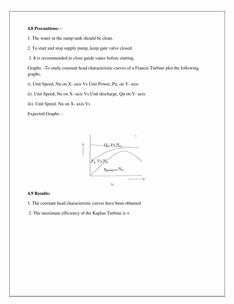
Graphs: -To study constant head characteristic curves of a Francis Turbine plot the following
graphs,
i). Unit Speed, Nu on X- axis Vs Unit Power, Pu, on Y- axis ii). Unit Speed, Nu on X- axis Vs Unit discharge, Qu on Y- axis iii). Unit Speed, Nu on X- axis Vs Expected Graphs: -
4.9 Results:
1. The constant head characteristic curves have been obtained 2. The maximum efficiency of the Kaplan Turbine is =

22
EXPERIMENT-5
PERFORMANCE TEST ON SINGLE STAGE CENTRIFUGAL PUMP
5.1Objective: To conduct a test at various heads of given single stage centrifugal pump and
to find its efficiency.
5.2RESOURCES:
S.NO Name of the equipment QTY
1 Single stage centrifugal pump
2 stop watch
3 collecting tank
4
5.3 Introduction:-
Closed Circuit Self sufficient portable package system Experimental Single stage
Centrifugal pump Test Rig is designed to study the performance of the Single stage Centrifugal
pump. In this equipment one can study the relationship between
1. Discharge Vs Head
2. Discharge Vs Input power
3. Discharge Vs Efficiency
The apparatus is designed to study the performance of a single stage Centrifugal Pump.
The readings to be taken on the single stage centrifugal pump are (1) Total Head (2) Discharge
(3) Power input and (4) Efficiency. Provision has been made to measure all these and hence the
complete characteristics of the single stage Centrifugal pump in question can be studied.
First prime the pump and start the motor. While starting closing and delivery valve and
the gauge cocks. Then slowly open the delivery valve and adjust to the required total head. The
total head is measured with the help of the pressure gauge. Total head is the sum of the pressure
head, Velocity head and the datum head.
Discharge is the amount of liquid the pump delivers over a definite period of time. It is
usually expressed in liter per minute. The actual discharge is measured with the help of the
measuring tank. In this case the power input into the pump cannot be measured directly. Hence
the power input into the AC motor is measured with the help of the energy meter connected in
the line.
Efficiency is the relation between the power input into the pump and the power output
from the pump. The power output from the pump is directly proportional to the total head and
discharge. As the power input into the pump cannot be measured the power input into the motor
only is taken into account and the overall efficiency of the pump is calculated.
If the total head (H) is measured in meters and the discharge (Q) in liter per minute, the
HQ/6120 gives the output in kW. The kilowatt input to the motor is measured with the help of
the meter constant stamped on the energy meter. The efficiency is calculated by dividing the
output by input.

For a particular desired speed of the pump, the entire above variable can be studied
individually, thus the complete characteristics can be studied.
23
5.4 Theory:
Centrifugal pump consisting of one impeller the pump is called the single stage
centrifugal pump. The impeller may be mounted on the same shaft. In this pump the liquid is
made to rotate in a closed chamber (volute casing) thus creating the centrifugal action which
gradually builds the pressure gradient towards outlet thus resulting in the continuous flow, the
pressure gradually.
5.5 Description:-
The Test Rig mainly consists of (1) single stage centrifugal pump set (2) Panel Board, (3)
Pressure and vacuum gauges to measure the head (4) SS Measuring Tank to measure the
discharge (5) Energy meter to measure the input to the motor and .(6) SS Sump.
MULTI STAGE CENTRIFUGAL PUMPSET: The pump set is of special design, horizontal spindle, and vertical split case. The pump is
of such a size, type & design that 1) The total head 2) Discharge and 3) Power requirements at
normal speed is well suited for the experimental purposes in technical institutions.
A.C. MOTOR: The electric motor suitable for operation on 50 HZ A.C. Supply is provided.
GAUGES: Suitable range of pressure and vacuum gauges to measure the total head on the pump
with reasonable accuracy
SS MEASURING TANK: It is provided to measure the discharge of the pump. The tank is complete with piezo
meter and scale arrangement.
PIPING SYSTEM: Suitable piping system with pipes, bends and valves are provided. A Simple strainer
valve is provided on the suction side to prevent any foreign matter entering into the pump. The
gate valve is provided in the delivery side to control the head on the pump. While starting the
motor always keep the valve in close position.
PANEL BOARD: The Panel Board houses all the necessary electrical items, like switch for the above pump
set and an energy meter to read the power input and it is fitted with the unit on a strong iron base
with sufficient height and with provisions for foundation.
INPUT POWER MEASUREMENT: A Kilowatt-hour meter is provided to measure the power input to the motor. The energy
meter constant (The Number of Revolutions per minute of the energy meter Disc) is stamped on
the meter from this the input power can be easily calculated.
SS SUMP: Is provided to store sufficient water for independent circulation through the unit for
experimentation and arranged within the floor space of the main unit.

24
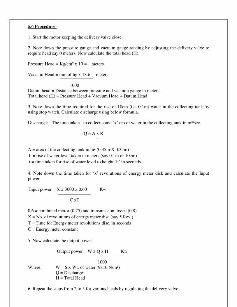
5.6 Procedure:-
1. Start the motor keeping the delivery valve close.
2. Note down the pressure gauge and vacuum gauge reading by adjusting the delivery valve to
require head say 0 meters. Now calculate the total head (H).
Pressure Head = Kg/cm² x 10 = meters.
Vaccum Head = mm of hg x 13.6 meters
1000
Datum head = Distance between pressure and vacuum gauge in meters
Total head (H) = Pressure Head + Vacuum Head + Datum Head
3. Note down the time required for the rise of 10cm (i.e. 0.1m) water in the collecting tank by
using stop watch. Calculate discharge using below formula.
Discharge: - The time taken to collect some ‘x’ cm of water in the collecting tank in m³/sec.
Q = A x R
t
A = area of the collecting tank in m² (0.35m X 0.35m)
h = rise of water level taken in meters (say 0.1m or 10cm)
t = time taken for rise of water level to height ‘h’ in seconds.
4. Note down the time taken for ‘x’ revolutions of energy meter disk and calculate the Input
power
Input power = X x 3600 x 0.60 Kw
C xT
0.6 = combined motor (0.75) and transmission losses (0.8).
X = No. of revolutions of energy meter disc (say 5 Rev.)
T = Time for Energy meter revolutions disc. in seconds
C = Energy meter constant
5. Now calculate the output power
Output power = W x Q x H Kw
1000
Where: W = Sp. Wt. of water (9810 N/m³)
Q = Discharge
H = Total Head
6. Repeat the steps from 2 to 5 for various heads by regulating the delivery valve.

25
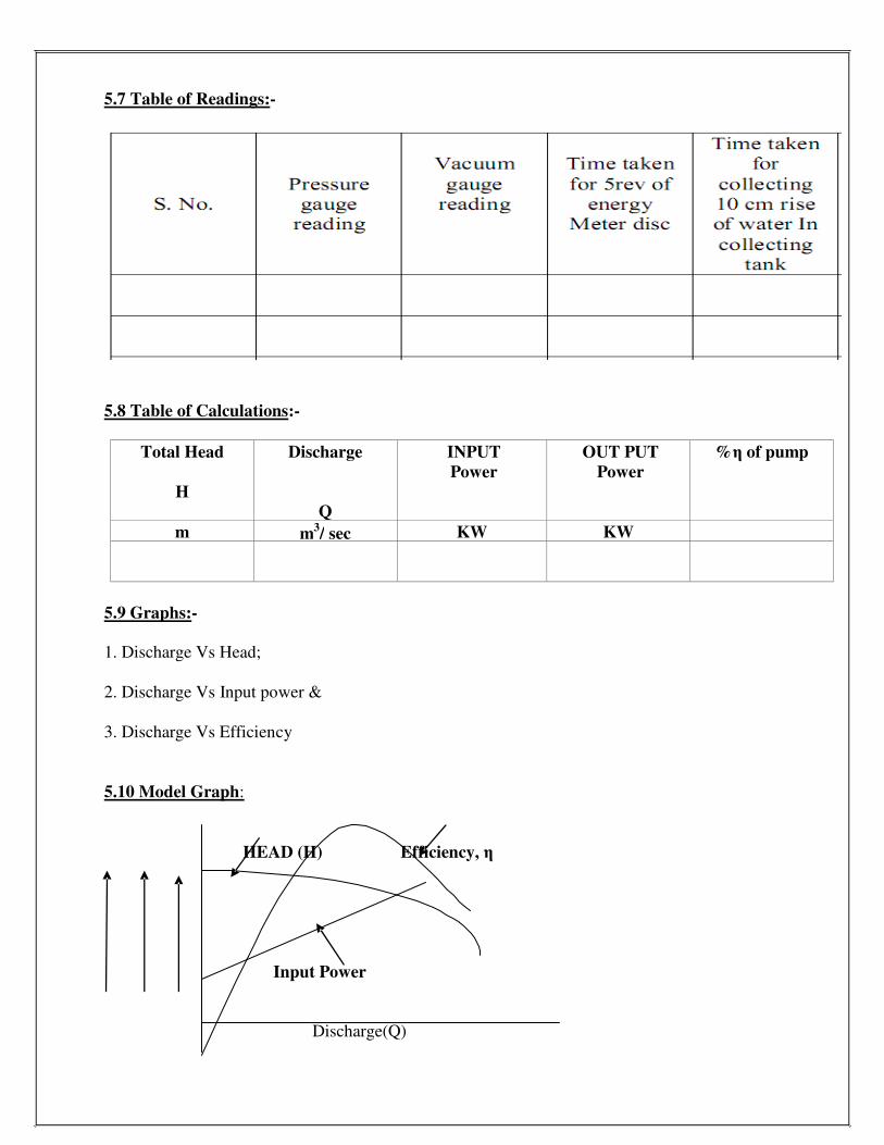
5.7 Table of Readings:-
5.8 Table of Calculations:-
Total Head
H
Discharge
Q
INPUT
Power
OUT PUT
Power
%η of pump
m m3/ sec KW KW
5.9 Graphs:-
1. Discharge Vs Head;
2. Discharge Vs Input power &
3. Discharge Vs Efficiency
5.10 Model Graph:
HEAD (H) Efficiency, η
Input Power
Discharge(Q)

26
5.11 Precautions:-
1. Priming is must before starting the pump.
2. Pump should never be run empty.
3. Use clean water in the sump tank.
5.12 RESULTS:-
1. Input power = k.w
2. Output Power = k.w
3. %η of pump =

27
EXPERIMENT-6
PERFORMANCE TEST ON MULTISTAGE CENTRIFUGAL PUMP
6.1OBJECTIVE: To conduct a test at various heads of given multistage centrifugal pump
and to find its efficiency.
6.2 RESOURCES :
S.NO Name of the equipment QTY
1 Multistage centrifugal pump
2 stop watch
3 collecting tank
4
6.3 Introduction:-
Closed Circuit Self sufficient portable package system Experimental Multi stage
Centrifugal pump Test Rig is designed to study the performance of the Multi stage Centrifugal
pump. In this equipment one can study the relationship between
1. Discharge Vs Head
2. Discharge Vs Input power
3. Discharge Vs Efficiency
The apparatus is designed to study the performance of a multi stage Centrifugal Pump.
The readings to be taken on the single stage centrifugal pump are (1) Total Head (2) Discharge
(3) Power input and (4) Efficiency. Provision has been made to measure all these and hence the
complete characteristics of the single stage Centrifugal pump in question can be studied.
First prime the pump and start the motor. While starting closing and delivery valve and
the gauge cocks. Then slowly open the delivery valve and adjust to the required total head. The
total head is measured with the help of the pressure gauge. Total head is the sum of the pressure
head, Velocity head and the datum head.
Discharge is the amount of liquid the pump delivers over a definite period of time. It is
usually expressed in liter per minute. The actual discharge is measured with the help of the
measuring tank. In this case the power input into the pump cannot be measured directly. Hence
the power input into the AC motor is measured with the help of the energy meter connected in
the line.
Efficiency is the relation between the power input into the pump and the power output
from the pump. The power output from the pump is directly proportional to the total head and
discharge. As the power input into the pump cannot be measured the power input into the motor
only is taken into account and the overall efficiency of the pump is calculated.
If the total head (H) is measured in meters and the discharge (Q) in liter per minute, the
HQ/6120 gives the output in kW. The kilowatt input to the motor is measured with the help of
the meter constant stamped on the energy meter. The efficiency is calculated by dividing the
output by input.
For a particular desired speed of the pump, the entire above variable can be studied
individually, thus the complete characteristics can be studied.
28
6.4 Theory:
Centrifugal pump consisting of two or more impellers the pump is called the multistage
centrifugal pump. The impeller may be mounted on the same shaft or on different shafts. In this
pump the liquid is made to rotate in a closed chamber (volute casing) thus creating the
centrifugal action which gradually builds the pressure gradient towards outlet thus resulting in
the continuous flow, the pressure gradually builds up in successive stages. The multistage
centrifugal pumps have the following functions;
1. To produce high heads.
2. To produce large quantities of liquids.
If a high head is required the impellers are connected in series (on the same Shaft) while
the discharge is required to be large the impellers are connected in parallel. These pumps are
more suitable for handling viscous, turbid (muddy) liquids.
6.5 Description:-
The Test Rig mainly consists of (1) Multi stage centrifugal pump set (2) Panel Board, (3)
Pressure and vacuum gauges to measure the head (4) SS Measuring Tank to measure the
discharge (5) Energy meter to measure the input to the motor and .(6) SS Sump.
MULTI STAGE CENTRIFUGAL PUMPSET: The pump set is of special design, horizontal spindle, and vertical split case. The pump is
of such a size, type & design that 1) The total head 2) Discharge and 3) Power requirements at
normal speed is well suited for the experimental purposes in technical institutions.
A.C. MOTOR: The electric motor suitable for operation on 50 HZ A.C. Supply is provided.
GAUGES: Suitable range of pressure and vacuum gauges to measure the total head on the pump
with reasonable accuracy
SS MEASURING TANK: It is provided to measure the discharge of the pump. The tank is complete with piezo
meter and scale arrangement.
PIPING SYSTEM: Suitable piping system with pipes, bends and valves are provided. A Simple strainer
valve is provided on the suction side to prevent any foreign matter entering into the pump. The
gate valve is provided in the delivery side to control the head on the pump. While starting the
motor always keep the valve in close position.
PANEL BOARD: The Panel Board houses all the necessary electrical items, like switch for the above pump
set and an energy meter to read the power input and it is fitted with the unit on a strong iron base
with sufficient height and with provisions for foundation.

29
INPUT POWER MEASUREMENT: A Kilowatt-hour meter is provided to measure the power input to the motor. The energy
meter constant (The Number of Revolutions per minute of the energy meter Disc) is stamped on
the meter from this the input power can be easily calculated.
SS SUMP: Is provided to store sufficient water for independent circulation through the unit for
experimentation and arranged within the floor space of the main unit.
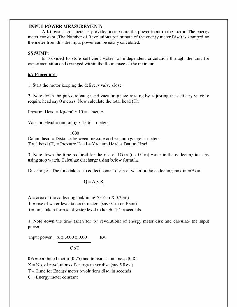
6.7 Procedure:-
1. Start the motor keeping the delivery valve close.
2. Note down the pressure gauge and vacuum gauge reading by adjusting the delivery valve to
require head say 0 meters. Now calculate the total head (H).
Pressure Head = Kg/cm² x 10 = meters.
Vaccum Head = mm of hg x 13.6 meters
1000
Datum head = Distance between pressure and vacuum gauge in meters
Total head (H) = Pressure Head + Vacuum Head + Datum Head
3. Note down the time required for the rise of 10cm (i.e. 0.1m) water in the collecting tank by
using stop watch. Calculate discharge using below formula.
Discharge: - The time taken to collect some ‘x’ cm of water in the collecting tank in m³/sec.
Q = A x R
t
A = area of the collecting tank in m² (0.35m X 0.35m)
h = rise of water level taken in meters (say 0.1m or 10cm)
t = time taken for rise of water level to height ‘h’ in seconds.
4. Note down the time taken for ‘x’ revolutions of energy meter disk and calculate the Input
power
Input power = X x 3600 x 0.60 Kw
C xT
0.6 = combined motor (0.75) and transmission losses (0.8).
X = No. of revolutions of energy meter disc (say 5 Rev.)
T = Time for Energy meter revolutions disc. in seconds
C = Energy meter constant

30
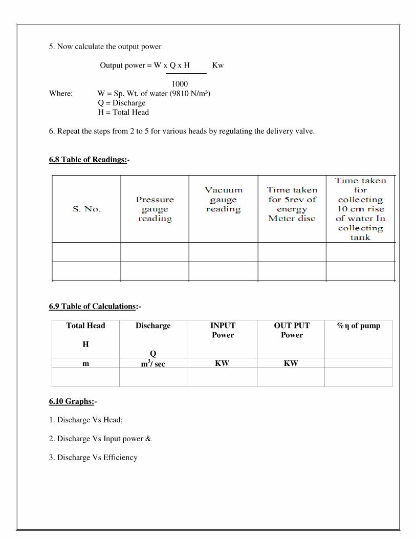
5. Now calculate the output power
Output power = W x Q x H Kw
1000
Where: W = Sp. Wt. of water (9810 N/m³)
Q = Discharge
H = Total Head
6. Repeat the steps from 2 to 5 for various heads by regulating the delivery valve.
6.8 Table of Readings:-
6.9 Table of Calculations:-
Total Head
H
Discharge
Q
INPUT
Power
OUT PUT
Power
%η of pump
m m3/ sec KW KW
6.10 Graphs:-
1. Discharge Vs Head;
2. Discharge Vs Input power &
3. Discharge Vs Efficiency

31
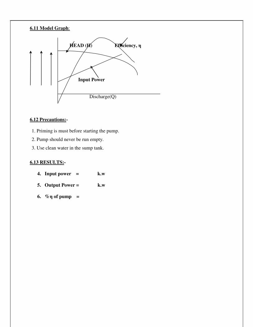
6.11 Model Graph:
HEAD (H) Efficiency, η
Input Power
Discharge(Q)
6.12 Precautions:-
1. Priming is must before starting the pump.
2. Pump should never be run empty.
3. Use clean water in the sump tank.
6.13 RESULTS:-
4. Input power = k.w
5. Output Power = k.w
6. %η of pump =

32
6.14 Viva Voce Questions:
1 What is priming of a pump?
Ans. Priming of a centrifugal pump is defined as the operation in which the suction pipe, casing
of the pump and a portion of the delivery pipe up to the delivery valve is completely filled from
outside source with the liquid to be raised by the pump before starting the pump. Thus the air
from these parts of the pump is removed and these parts are filled with liquid to be pumped.
2 Why it is necessary to prime a pump?
Ans. The density of air is very low, the generated head of air in terms of equivalent metre of
water head is negligible and hence the water may not be sucked from the pump. To avoid this
difficulty, priming is necessary.
3 What is cavitation? Where does it occur in a centrifugal pump?
Ans. Cavitation is defined as the phenomenon of formation of vapour bubbles of a flowing
liquid in a region where the pressure of the liquid falls below its vapour pressure and sudden
collapsing of these vapour bubbles in a region of higher pressure.
4 Write the effects of cavitation?
Ans. The following are the effects of cavitations:
1. The metallic surfaces are damaged and cavities are formed on the surfaces.
2. Due to the sudden collapse of vapour bubble, considerable noise and vibrations are
produced.
3. The efficiency of a turbine decreases.
5 What are the main parts of a centrifugal pump?
Ans. Impeller, Casting, Suction pipe with a foot valve & a strainer and Delivery pipe
6 Distinguish between the positive and non-positive displacement pumps.
Ans. Positive displacement pump: It causes a fluid to move by trapping a fixed amount of it
then forcing (displacing) that trapped volume into the discharge pipe.
E.g. Lobe, gear, screw, vage pump etc.
Non-positive displacement pump (rotodynamic pump): It is pump in which the dynamic motion
of a fluid is increased by pump action.
E.g. centrifugal, turbine, propeller etc.
7 The centrifugal pump acts as a ---- reverse of an inward radial flow reaction turbine
8 Define pumps?
Ans. The hydraulic machines which convert the mechanical energy into hydraulic energy are
called pumps.

33
9 Define a centrifugal pump?
Ans. The hydraulic energy is in the form of pressure energy. If the mechanical energy is
converted, into pressure energy by means of centrifugal force acting on the fluid, the hydraulic
machine is called centrifugal pump.
10 Write the working principle of a centrifugal pump?
Ans. It works on the principle of forced vortex flow which means that when a certain mass of
liquid is rotated by an external torque, the rise in pressure head of the rotating liquid takes
place.
11 Define the following terms:
(i)Suction head (ii) Delivery head (iii) Static head (iv) Manometric head
Ans. 1.Suction head— It is the vertical height of the centre line of the centrifugal pump above
the water surface in the tank or pump from which water is to be lifted. This height is also called
suction lift. It is denoted by ‘hs’.
2. Delivery head -The vertical distance between the centre line of the pump and the water
surface in the tank to which water is delivered is known as delivery head. It is denoted by
‘hd’.
3. Static head-The sum of suction head and delivery head is known as static head. This is
represented by ‘Hs’
4. Manometric Head -The manometric head is defined as the head against which a
centrifugal pump has to work. It is denoted by ‘Hm’.
12 Write the Efficiencies of a centrifugal pump?
Ans. 1. Manometric efficiency -The ratio of the manometric head to the head
imparted by the impeller to the water is known as manometric efficiency.
2. Mechanical efficiency- The ratio of the power available at the impeller to the power
at the shaft of the centrifugal pump is known as mechanical efficiency.
3. Overall efficiency- The ratio of power output of the pump to the power input to the
pump
13 Define a multistage centrifugal pump?
Ans. If a centrifugal pump consists of two or more impellers, the pump is called a
multistage centrifugal pump. The impellers may be mounted on the same shaft or on
different shafts.
14 Write two important functions of a multistage centrifugal pump
Ans. A multistage pump is having the following two important functions:
1. To produce a high head 2. To discharge a large quantity of liquid
15 Define specific speed of a centrifugal pump?
Ans. It is defined as the speed of a geometrically similar pump which would deliver one
cubic metre of liquid per second against a head of one metre. It is denoted by ‘Ns’.

34
16 Define the characteristic curves and why these curves are necessary?
Ans. Characteristic curves of centrifugal pumps are defined those curves which are plotted
from the results of a number of tests on the centrifugal pump. These curves are necessary to
predict the behavior and performance of the pump when the pump is working under different
floe rate, head and speed.
17 Write the types of the characteristic curves?
Ans. 1. Main characteristic curves or Constant head curve, 2. Operating characteristic curves or
Constant speed curve, and 3. Constant efficiency or Muschel curves.
18 What is priming of centrifugal pump?
Ans. The filling of suction pipe, impeller casing and delivery pipe upto delivery valve by the
liquid from outside source before starting the pump is known as priming.
The air is removed and that portion is filled with the liquid to be pumped.
19 What is the principle of working of a Centrifugal Pump?
Ans. It is very clear that the principle used for centrifugal pump is the centrifugal force in the
form of dynamic pressure which is generated by rotary motion of one or more rotating wheels
called the impellers.
20 Classify hydraulic pumps.
Ans. Pumps may be placed in one of the two general categories.
(i) Dynamic pressure pumps: centrifugal pump, jet pump, propeller, and turbine.
(ii) Positive, displacement pump: Piston plunger, gear, lab, vane, screw etc.

35
EXPERIMENT-7
PERFORMANCE TEST ON RECIPROCATING PUMP 7.1OBJECTIVE: To conduct a test at various heads of given reciprocating pump finds its efficiency.
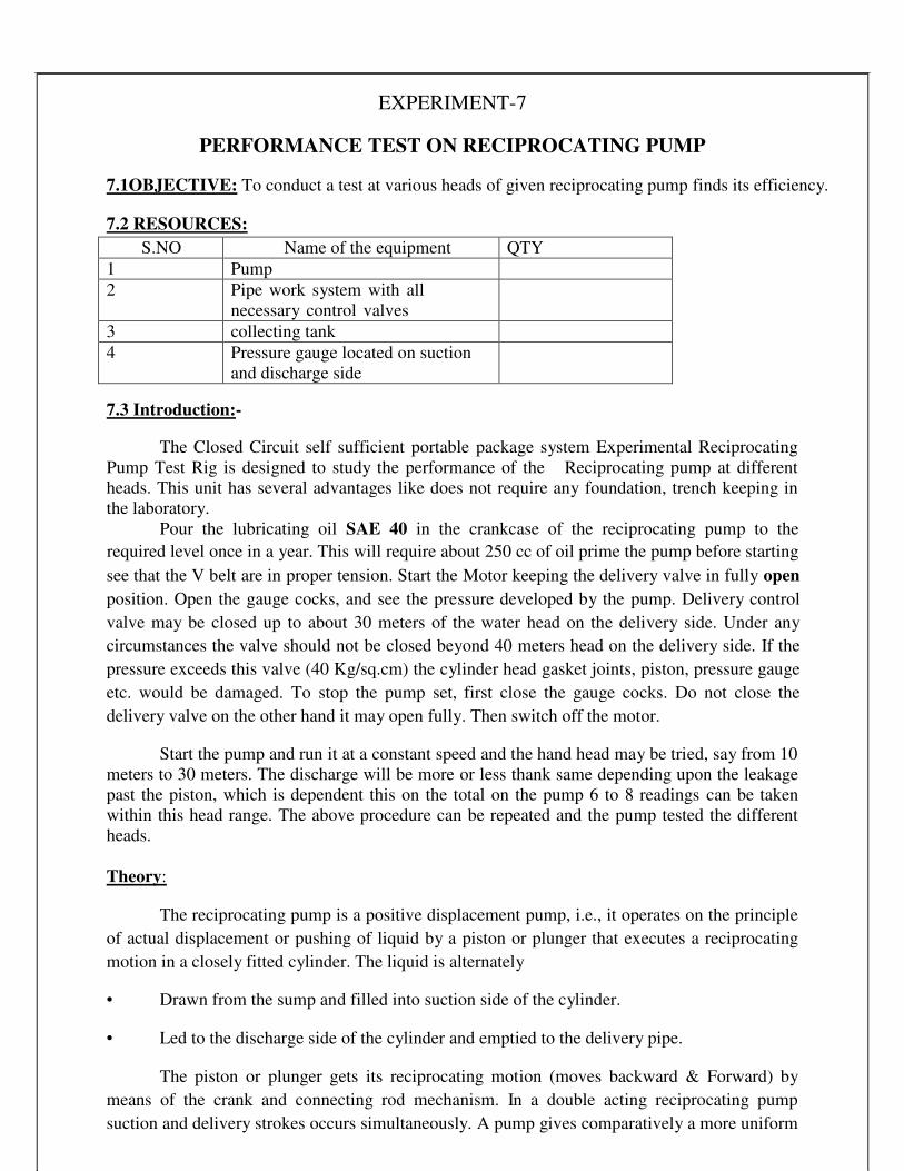
7.2 RESOURCES:
S.NO Name of the equipment QTY
1 Pump
2 Pipe work system with all
necessary control valves
3 collecting tank
4 Pressure gauge located on suction
and discharge side
7.3 Introduction:-
The Closed Circuit self sufficient portable package system Experimental Reciprocating
Pump Test Rig is designed to study the performance of the Reciprocating pump at different
heads. This unit has several advantages like does not require any foundation, trench keeping in
the laboratory.
Pour the lubricating oil SAE 40 in the crankcase of the reciprocating pump to the
required level once in a year. This will require about 250 cc of oil prime the pump before starting
see that the V belt are in proper tension. Start the Motor keeping the delivery valve in fully open
position. Open the gauge cocks, and see the pressure developed by the pump. Delivery control
valve may be closed up to about 30 meters of the water head on the delivery side. Under any
circumstances the valve should not be closed beyond 40 meters head on the delivery side. If the
pressure exceeds this valve (40 Kg/sq.cm) the cylinder head gasket joints, piston, pressure gauge
etc. would be damaged. To stop the pump set, first close the gauge cocks. Do not close the
delivery valve on the other hand it may open fully. Then switch off the motor.
Start the pump and run it at a constant speed and the hand head may be tried, say from 10
meters to 30 meters. The discharge will be more or less thank same depending upon the leakage
past the piston, which is dependent this on the total on the pump 6 to 8 readings can be taken
within this head range. The above procedure can be repeated and the pump tested the different
heads.
Theory:
The reciprocating pump is a positive displacement pump, i.e., it operates on the principle
of actual displacement or pushing of liquid by a piston or plunger that executes a reciprocating
motion in a closely fitted cylinder. The liquid is alternately
• Drawn from the sump and filled into suction side of the cylinder. • Led to the discharge side of the cylinder and emptied to the delivery pipe.
The piston or plunger gets its reciprocating motion (moves backward & Forward) by
means of the crank and connecting rod mechanism. In a double acting reciprocating pump
suction and delivery strokes occurs simultaneously. A pump gives comparatively a more uniform

discharge than the single acting pump, because of the continuity of suction and delivery strokes.
36
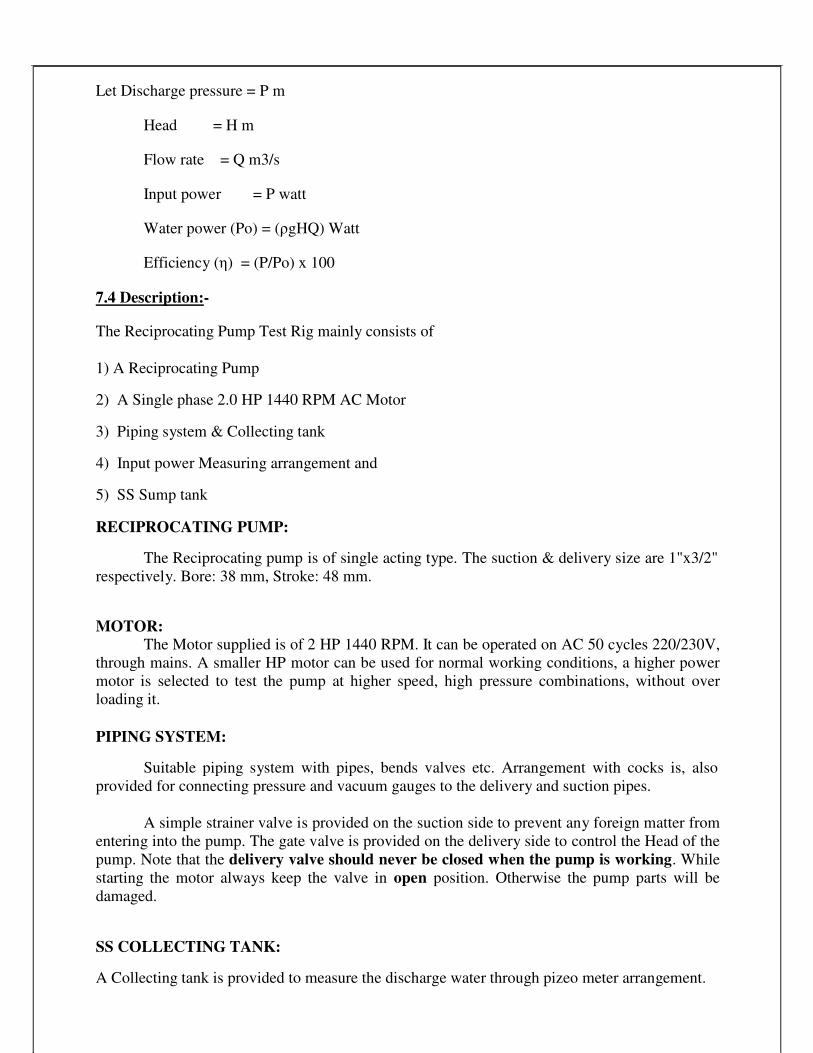
Let Discharge pressure = P m
Head = H m
Flow rate = Q m3/s
Input power = P watt
Water power (Po) = (ρgHQ) Watt
Efficiency (η) = (P/Po) x 100
7.4 Description:-
The Reciprocating Pump Test Rig mainly consists of
1) A Reciprocating Pump
2) A Single phase 2.0 HP 1440 RPM AC Motor
3) Piping system & Collecting tank
4) Input power Measuring arrangement and
5) SS Sump tank
RECIPROCATING PUMP:
The Reciprocating pump is of single acting type. The suction & delivery size are 1"x3/2"
respectively. Bore: 38 mm, Stroke: 48 mm.
MOTOR: The Motor supplied is of 2 HP 1440 RPM. It can be operated on AC 50 cycles 220/230V,
through mains. A smaller HP motor can be used for normal working conditions, a higher power
motor is selected to test the pump at higher speed, high pressure combinations, without over
loading it.
PIPING SYSTEM:
Suitable piping system with pipes, bends valves etc. Arrangement with cocks is, also
provided for connecting pressure and vacuum gauges to the delivery and suction pipes.
A simple strainer valve is provided on the suction side to prevent any foreign matter from
entering into the pump. The gate valve is provided on the delivery side to control the Head of the
pump. Note that the delivery valve should never be closed when the pump is working. While
starting the motor always keep the valve in open position. Otherwise the pump parts will be
damaged.
SS COLLECTING TANK:
A Collecting tank is provided to measure the discharge water through pizeo meter arrangement.

37
INPUT POWER MEASUREMENT: A Kilowatt-hour meter is provided to measure the power input to the motor. The energy
meter constant (The Number of Revolutions per minute of the energy meter Disc) is stamped on
the meter. From this the input power can be easily calculated.
SS SUMP: A Sump is provided compactly with in the (Floor space of the main unit to store adequate
water for circulation through the unit for experimentation)
7.5 Principle:-
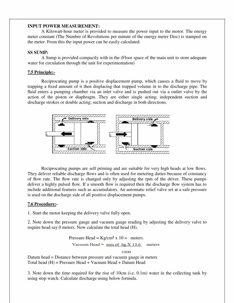
Reciprocating pump is a positive displacement pump, which causes a fluid to move by
trapping a fixed amount of it then displacing that trapped volume in to the discharge pipe. The
fluid enters a pumping chamber via an inlet valve and is pushed out via a outlet valve by the
action of the piston or diaphragm. They are either single acting; independent suction and
discharge strokes or double acting; suction and discharge in both directions.
Reciprocating pumps are self priming and are suitable for very high heads at low flows.
They deliver reliable discharge flows and is often used for metering duties because of constancy
of flow rate. The flow rate is changed only by adjusting the rpm of the driver. These pumps
deliver a highly pulsed flow. If a smooth flow is required then the discharge flow system has to
include additional features such as accumulators. An automatic relief valve set at a safe pressure
is used on the discharge side of all positive displacement pumps.
7.6 Procedure:-
1. Start the motor keeping the delivery valve fully open.
2. Note down the pressure gauge and vacuum gauge reading by adjusting the delivery valve to
require head say 0 meters. Now calculate the total head (H).
Pressure Head = Kg/cm² x 10 = meters.
Datum head = Distance between pressure and vacuum gauge in meters
Total head (H) = Pressure Head + Vacuum Head + Datum Head
3. Note down the time required for the rise of 10cm (i.e. 0.1m) water in the collecting tank by
using stop watch. Calculate discharge using below formula.

38
Discharge:- The time taken to collect some ‘x’ cm of water in the collecting tank in m³/sec.
A = area of the collecting tank in m² (0.3m X 0.3m)
h = rise of water level taken in meters (say 0.1m or 10cm)
t = time taken for rise of water level to height ‘h’ in seconds.
4. Note down the time taken for ‘x’ revolutions of energy meter disk and calculate the
Input power
Where, 0.70= Combined motor losses.
0.80 = Belt (or) transmission losses.
X = No. of revolutions of energy meter disc (say 5 Rev.)
T = Time for Energy meter revolutions disc. in seconds
C = Energy meter constant
5. Now calculate the output power
Where: W = Sp. Wt. of water (9810 N/m³)
Q = Discharge
H = Total Head
6. Repeat the steps from 2 to 5 for various heads by regulating the delivery valve.
Note: -- Maximum head should not exceed 2.5m (i.e. 2.5kg/sq. cm)
Check the lubricating oil SAE 40 in the crankcase of the reciprocating pump to the required level
i.e. 400ml.

39
7.7 Table of Readings:-
7.8 Table of Calculations:-
Total Head
H
Discharge
Q
INPUT
Power
OUT PUT
Power
%η of pump
m m3/ sec KW KW
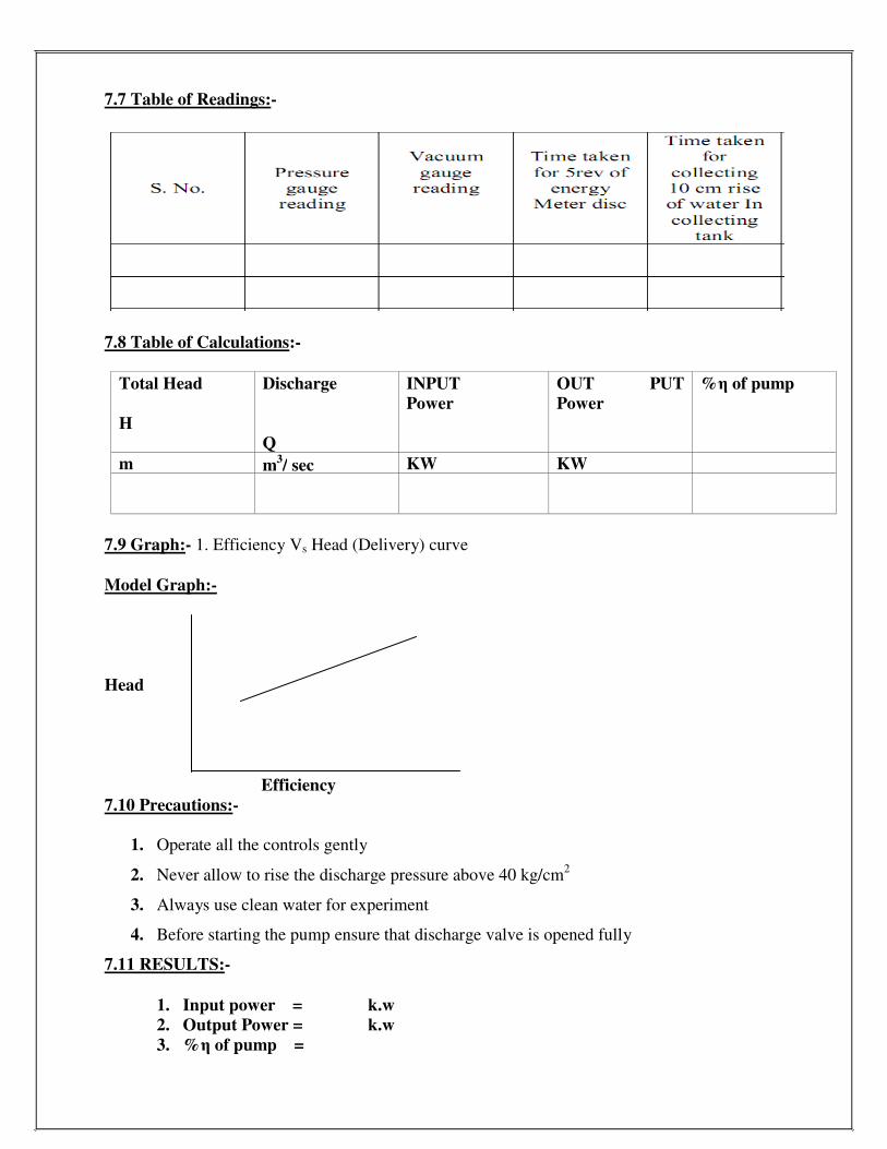
7.9 Graph:- 1. Efficiency Vs Head (Delivery) curve
Model Graph:-
Head
Efficiency
7.10 Precautions:-
1. Operate all the controls gently
2. Never allow to rise the discharge pressure above 40 kg/cm2
3. Always use clean water for experiment
4. Before starting the pump ensure that discharge valve is opened fully
7.11 RESULTS:-
1. Input power = k.w
2. Output Power = k.w
3. %η of pump =

40
7.12 Viva Voce Questions:
1 What is an air vessel?
Ans. An air vessel is a closed chamber containing compressed air in the top portion and liquid
at the bottom of the chamber.
2 What is negative slip in case of reciprocating pump?
Ans. If actual discharge is more than the theoretical discharge, the slip of the pump will become
–ve. In that case, the slip of the pump is known as negative slip.
It occurs when delivery pipe is short, suction pipe is long and pump is running at high speed.
3 What do you understand by single acting & double acting pump?
Ans. According to the water being in contact with one side or both sides of the piston:
If the water is in contact with one side of the piston, the pump is known as single acting. On
the other hand, if the water is in contact with both sides of the piston, the pump is called double
acting.
4 What is the function of air vessel in a reciprocating pump?
Ans. An air vessel is fitted to the suction pipe and to the delivery pipe at a point close to the
cylinder of a single-acting reciprocating pump:
i)to obtain a continuous supply of liquid at a uniform rate,
ii)to save a considerable amount of work in overcoming the frictional resistance in the
suction and delivery pipes, and
iii)to run the pump at a high speed without separation.
5 Define slip of a pump?
Ans. Slip of a pump is defined as the difference between the theoretical discharge and actual
discharge of the pump.
6 Define a reciprocating pump?
Ans. The mechanical energy is converted into hydraulic energy (or pressure energy) by sucking
the liquid into a cylinder in which a piston is reciprocating (moving backwards and forwards),
which exerts the thrust on the liquid and increases its hydraulic energy (pressure energy), the
pump is known as reciprocating pump.
7 What are the main parts of the reciprocating pump?
Ans. 1. A cylinder with a piston, piston rod, connecting rod and a crank, 2. Suction pipe, 3.
Delivery pipe, 4. Suction valve, and 5. Delivery valve.
8 Define slip of reciprocating pump?
Ans. The difference of theoretical discharge and actual discharge is known as slip of the pump

41
9 How do you classify the reciprocating pumps?
Ans. 1. According to the water being in contact with one side or both sides of the piston,
(i)Single acting pump (ii) Double acting pump
2. According to the number of cylinders provided.
(i)Single cylinder pump (ii) Double cylinder pump (iii) Triple cylinder pump
10 What is the principle of working of a reciprocating pump?
Ans. In reciprocating pumps the mechanical action causes the fluid to move using one or
more oscillating pistons, plungers etc. It requires a system of suction and discharge valves
to ensure that the fluid moves in a positive direction.
11 Define indicator diagram?
Ans. The indicator diagram for a reciprocating pump is defined as the graph between the
pressure head in the cylinder and the distance travelled by piston from inner dead centre for
one complete revolution of the cranck.
12 Write the formula for discharge through a pump per second for a single & double acting
reciprocating pumps?
Ans. (i) Discharge through a pump per second for a single acting reciprocating pump
Q=ALN/60
(ii) Discharge through a pump per second for a double acting reciprocating pump
Q=2ALN/60
Where A= Cross-sectional area of the piston
L=Length of the stroke
N=No. of revolution per second
13 What are the factors which influence the speed of reciprocating pump?
Ans. Speed of reciprocating pump is influenced by:
1. Absolute pressure inside the cylinder..
2. Cavitation produced.
3. It also affected with acceleration of piston
4. Friction in the pipes.

42
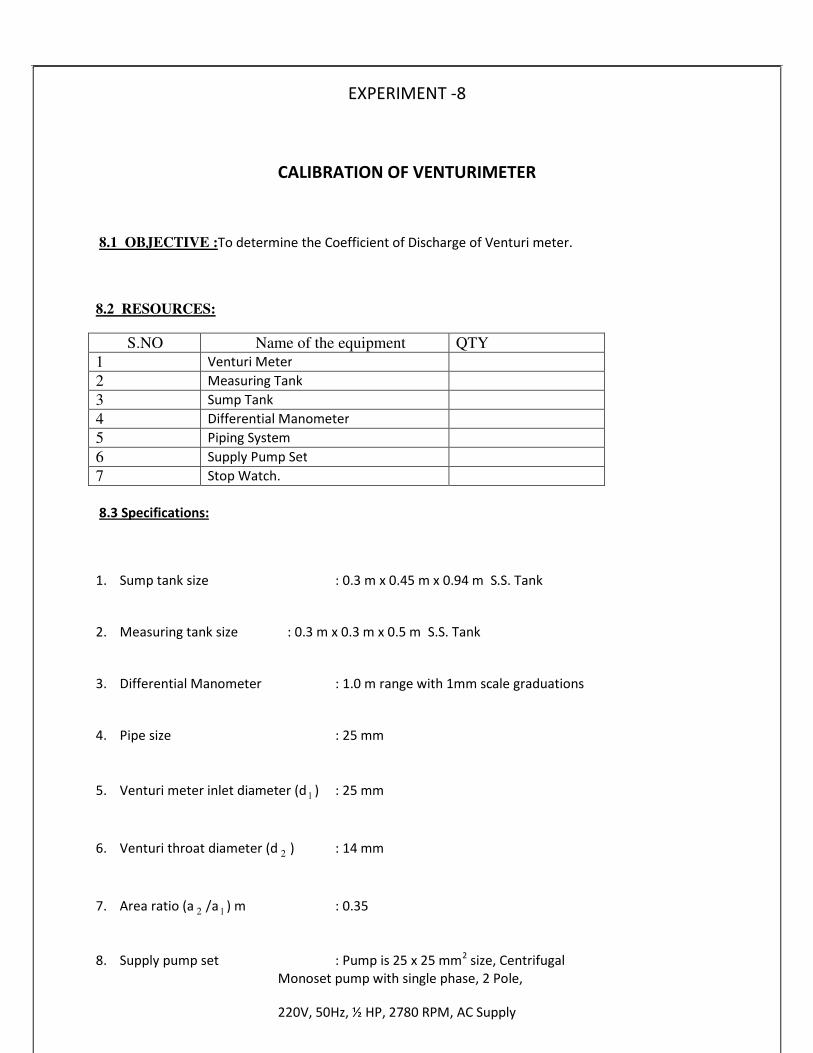
EXPERIMENT -8
CALIBRATION OF VENTURIMETER
8.1 OBJECTIVE :To determine the Coefficient of Discharge of Venturi meter.
8.2 RESOURCES:
S.NO Name of the equipment QTY
1 Venturi Meter
2 Measuring Tank
3 Sump Tank
4 Differential Manometer
5 Piping System
6 Supply Pump Set
7 Stop Watch.
8.3 Specifications:
1. Sump tank size
2. Measuring tank size
3. Differential Manometer
4. Pipe size
: 0.3 m x 0.45 m x 0.94 m S.S. Tank
: 0.3 m x 0.3 m x 0.5 m S.S. Tank
: 1.0 m range with 1mm scale graduations
: 25 mm
5. Venturi meter inlet diameter (d 1 ) : 25 mm
6. Venturi throat diameter (d 2 ) : 14 mm
7. Area ratio (a 2 /a 1 ) m : 0.35
8. Supply pump set : Pump is 25 x 25 mm2
size, Centrifugal
Monoset pump with single phase, 2 Pole,
220V, 50Hz, ½ HP, 2780 RPM, AC Supply

43
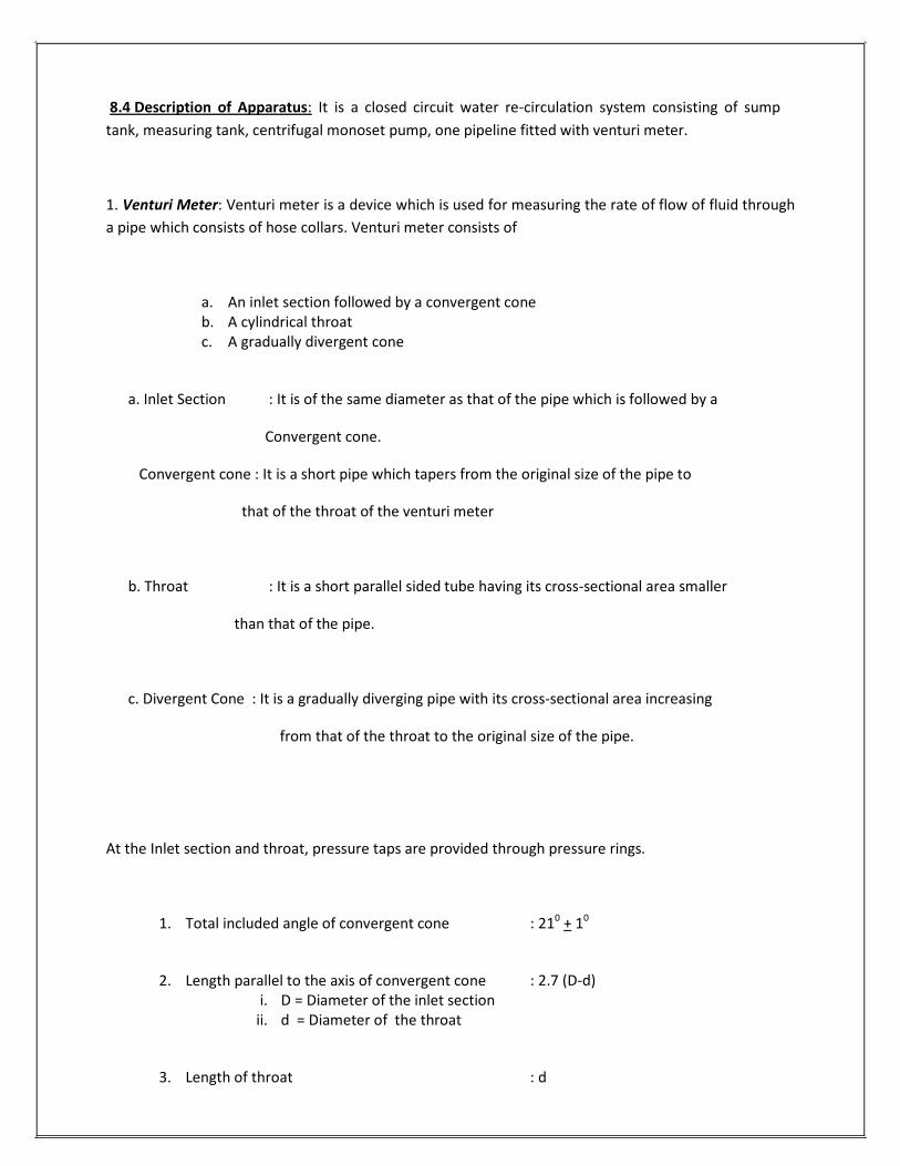
8.4 Description of Apparatus: It is a closed circuit water re-circulation system consisting of sump
tank, measuring tank, centrifugal monoset pump, one pipeline fitted with venturi meter.
1. Venturi Meter: Venturi meter is a device which is used for measuring the rate of flow of fluid through
a pipe which consists of hose collars. Venturi meter consists of
a. An inlet section followed by a convergent cone
b. A cylindrical throat c. A gradually divergent cone
a. Inlet Section : It is of the same diameter as that of the pipe which is followed by a
Convergent cone.
Convergent cone : It is a short pipe which tapers from the original size of the pipe to
that of the throat of the venturi meter
b. Throat : It is a short parallel sided tube having its cross-sectional area smaller
than that of the pipe.
c. Divergent Cone : It is a gradually diverging pipe with its cross-sectional area increasing
from that of the throat to the original size of the pipe.
At the Inlet section and throat, pressure taps are provided through pressure rings.
1. Total included angle of convergent cone
2. Length parallel to the axis of convergent cone
i. D = Diameter of the inlet section ii. d = Diameter of the throat
3. Length of throat
: 210
+ 10
: 2.7 (D-d)
: d

44
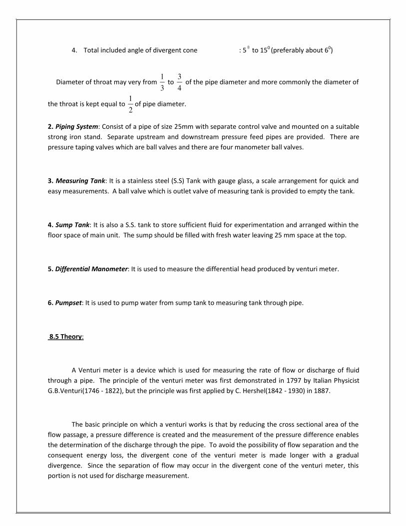
4. Total included angle of divergent cone : 50
to 150
(preferably about 60)
Diameter of throat may very from 3
to 4
of the pipe diameter and more commonly the diameter of
the throat is kept equal to 2
of pipe diameter.
2. Piping System: Consist of a pipe of size 25mm with separate control valve and mounted on a suitable
strong iron stand. Separate upstream and downstream pressure feed pipes are provided. There are
pressure taping valves which are ball valves and there are four manometer ball valves.
3. Measuring Tank: It is a stainless steel (S.S) Tank with gauge glass, a scale arrangement for quick and
easy measurements. A ball valve which is outlet valve of measuring tank is provided to empty the tank.
4. Sump Tank: It is also a S.S. tank to store sufficient fluid for experimentation and arranged within the
floor space of main unit. The sump should be filled with fresh water leaving 25 mm space at the top.
5. Differential Manometer: It is used to measure the differential head produced by venturi meter.
6. Pumpset: It is used to pump water from sump tank to measuring tank through pipe.
8.5 Theory:
A Venturi meter is a device which is used for measuring the rate of flow or discharge of fluid
through a pipe. The principle of the venturi meter was first demonstrated in 1797 by Italian Physicist
G.B.Venturi(1746 - 1822), but the principle was first applied by C. Hershel(1842 - 1930) in 1887.
The basic principle on which a venturi works is that by reducing the cross sectional area of the
flow passage, a pressure difference is created and the measurement of the pressure difference enables
the determination of the discharge through the pipe. To avoid the possibility of flow separation and the
consequent energy loss, the divergent cone of the venturi meter is made longer with a gradual
divergence. Since the separation of flow may occur in the divergent cone of the venturi meter, this
portion is not used for discharge measurement.
1 3
1

45
Since the cross sectional area of the throat is smaller than the cross-sectional area of the inlet
section, the velocity of flow at the throat will become greater than that at the inlet section, according to
continuity equation. The increase in the velocity of flow at the throat results in the decrease in the
pressure at this section. As such a pressure difference is developed between the inlet section and the
throat of the venturi meter. The pressure difference between these sections can be determined by
connecting a differential manometer. The formation of vapour and air pockets in the liquid results in a
phenomenon called cavitation which is not desirable. In order to avoid cavitation to occur, the diameter
of the throat can be reduced only up to a certain limited value.
8.6 Procedure:
1. Before starting the experiment, do priming of pump to remove air bubbles by pouring water in
the priming device. 2. Then open the inlet valve of the piping system of pump and Venturi meter pipe outlet valve and
close orifice meter pipe outlet valve. 3. Start the motor and open the pressure feed pipes valves to remove the air bubbles if any. 4. Close all the valves, except upstream and downstream ball valves of pipes connected with
Venturi meter.
5. Note the readings in differential manometer
6. Close the outlet valve of measuring tank and note the 10 cm raise of water using stop watch
7. Repeat the process 3 to 4 times and note the values for different flow rates of water. 8. After conducting experiment close all the pressure feed pipe valves and switch off the power
supply.
8.7 Formulae:
Actual discharge:
Actual discharge (Q act ) = A.R
m3/s
A = Area of measuring (or) collecting tank = 0.3 x 0.3 m2
R = Rise of water level taken in meters (say 0.1 m or 10 cm)
t = time taken for rise of water level to rise ‘R’ in ‘t’ seconds
The actual discharge is measured with the help of measuring tank and by noting the time for definite
raise of water level in the tank
t

46
Theoretical discharge:
Theoretical discharge (Q th ) = a1a2 2gh
m3/s
a1 − a2
Where
h = (h − h )
(S1 − S2 ) / 100 m of water
2
h 1 -h 2 = Difference in Manometric liquid in cm
S 1 = Specific gravity of Manometric liquid
S 2 = Specific gravity of flowing liquid
g = Acceleration due to gravity (9.81 m/s 2
)
a 1 = Inlet area of Venturi meter in m 2
a 2 = Area of throat in m 2
Coefficient of discharge:
Coefficient of discharge(C d ) = Qact
th
ActualDisch arg e
TheoriticalDisch arg e
2 2
Q=
1 2S

8.8 Table of Readings:
47

S.NO
Manometer reading
cm of hg
Manometer head h
cm
Time for (10 cm) rise
of water level t
in Sec.
h 1
h 2
h m
8.9 Sample Calculations:
Area of inlet (a 1 ) = (
4
1 ) in m 2
=
Where
d1 = Venturi inlet diameter = 25 mm = 25x10-3
m
Area of throat (a 2 ) = (
4
2 ) in m 2
=
Where
d2 = Throat diameter = 14 mm = 14x10-3
m
Manometer head h in m =
3
Theoretical discharge of Venturi meter (Q th ) in s
=
Time for 100 mm rise in sec (t) =
2dπ
2dπ
m

48
3
Actual discharge of Venturi meter (Q act ) in s
=
Coefficient of discharge of Venturi meter (C d ) = Q
act
Qth
=
8.10 Table of Calculations:
S.NO
Actual Discharge
Qact
m3/sec
Theoretical Discharge
Qth
m3/sec
Coefficient of
Discharge
Cd = Qact / Qth
8.11 Precautions:
1. All the joints should be leak proof and water tight
2. Manometer should be filled to about half the height with mercury
3. All valves on the pressure feed pipes and manometer should be closed to prevent damage and
over loading of the manometer before starting the motor.
4. Ensure that gauge glass and meter scale assembly of the measuring tank is fixed vertically and
water tight
5. Ensure that the pump is primed before starting the motor
6. Remove the air bubbles in differential manometer by opening air release valves
7. Take the differential manometer readings without parallax error
8. Ensure that the electric switch does not come in contact with water
9. The water filled in the sump tank should be 2 inches below the upper end.
m

49
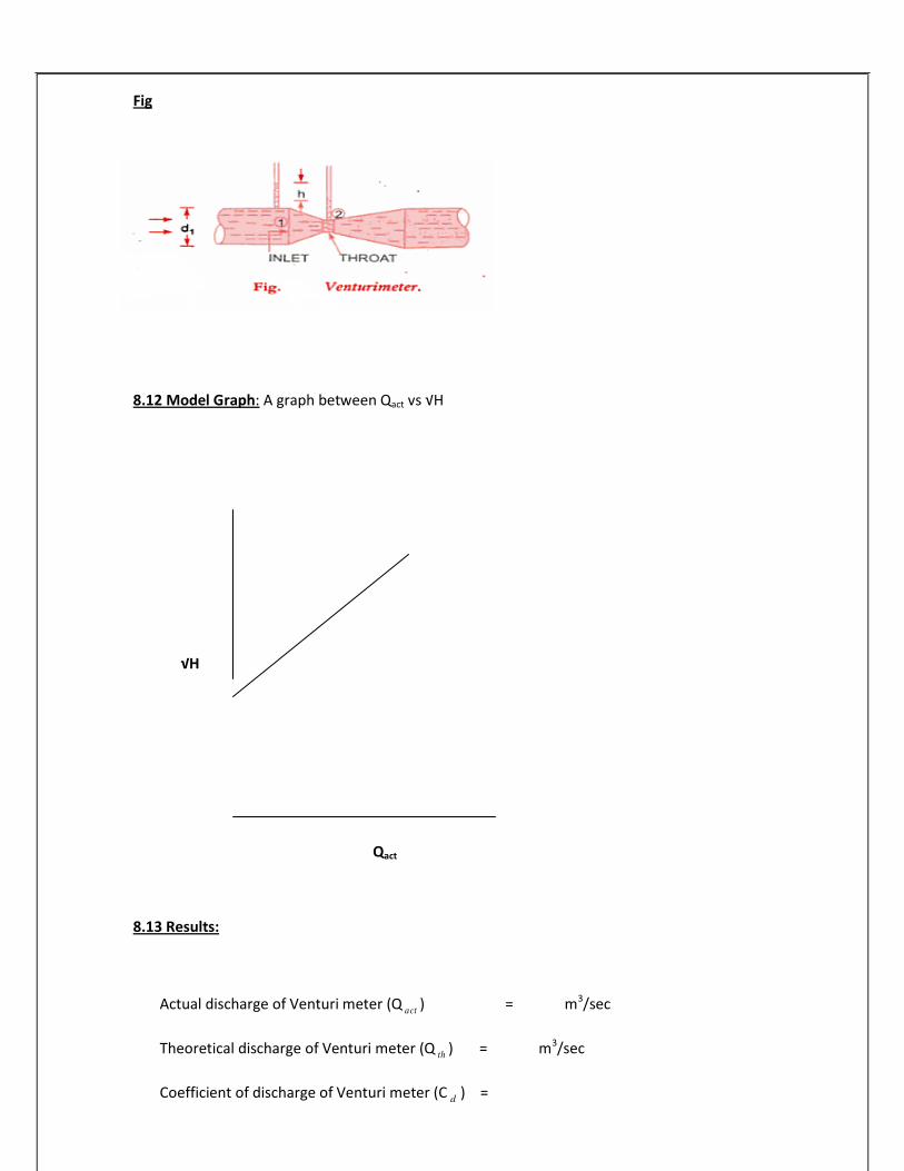
Fig
8.12 Model Graph: A graph between Qact vs √H
√H
Qact
8.13 Results:
Actual discharge of Venturi meter (Q act ) = m3/sec
Theoretical discharge of Venturi meter (Q th ) = m3/sec
Coefficient of discharge of Venturi meter (C d ) =

50
8.14 Viva Questions:
1. Who demonstrated the principle of Venturi meter first? A. The Principle of Venturi meter was first demonstrated in 1797 by Italian Physicist G.B. Venturi (1746
- 1822).
2. Who applied Venturi meter principle? A. C. Herschel (1842-1930) applied Venturi meter principle in 1887.
3. What is the basic principle of venturi meter? A. The basic principle on which a venturi meter works is that by reducing the cross-sectional area of the
flow passage, a pressure difference is created and the measurement of the pressure difference
enables the determination of the discharge through the pipe.
4. What are the parts of Venturi meter? A. a. An inlet section followed by a convergent cone
b. A Cylindrical throat
c. A gradually divergent cone
5. What is convergent cone? A. It is a short pipe which tapers from the original size of the pipe to that of the throat of the venturi
meter
6. What is throat of Venturi meter? A. The throat of the Venturi meter is a short parallel sided tube having its cross-sectional area smaller
than that of the pipe.
7. What is divergent cone? A. It is a gradually diverging pipe with its cross-sectional area increasing from that of the throat to the
original size of the pipe.
8. Where pressure taps are provided?
A. At the inlet section and throat.
9. What is the total included angle of convergent cone of Venturi meter?
A. 210
+ 10

51
10. What is the length of the convergent cone?
A. 2.7 (D-d)
D = Diameter of the inlet section
d = Diameter of the throat
11. What is the included angle of divergent cone?
A. 50
to 150
(preferably about 60)
12. Which part is smaller, convergent cone or divergent cone? Why? A. Convergent cone is smaller. To avoid the possibility of flow separation and the consequent energy
loss, the divergent cone of the venturi meter is made longer with a gradual divergence.
13. Where separation of flow occurs?
A. In Divergent cone of Venturi meter
14. Which portion is not used for discharge measurement?
A. Divergent cone
15. Which cross-sectional area is smaller than cross sectional area of inlet section?
A. Throat
16. Where velocity of flow greater?
A. Throat
17. Where pressure is low in Venturi meter?
A. Throat
18. How pressure difference is determined?
A. By connecting a differential manometer
19. Between which sections the pressure difference can be determined?
A. Inlet section and Throat
20. What we should do for getting greater accuracy in the measurement of the pressure difference?

52
A. The cross sectional area of the throat should be reduced so that the pressure at throat is very much
reduced.
21. What is cavitation? A. The formation of the vapour and air pockets in the liquid ultimately results in a phenomenon called
Cavitation.
22. What is value of diameter of throat? A. The diameter of throat may very from 1/3 to ¾ of the pipe diameter and more commonly the
diameter of the throat is kept equal to ½ of the pipe diameter.
23. What should be done to avoid cavitation?
A. The diameter of throat should be reduced only up to a certain limited value
24. Write the formula for actual discharge.
A. Q act = AR
25. Write the formula for theoretical discharge.
A. Q th = a1a2 2gh
a1 − a2
26. Write the co-efficient discharge
A. Coefficient of discharge (C d ) =
Qact
Qth
27. Venturi meter based on which principles?
A. Bemoulli’s equation.
28. What is the value of C d for Venturi meter?
A. It is less than 1 and it may be between 0.95 and 0.99.
29. What are the applications of Bernoulli’s equation?
A. Venturi meter, Orifice meter, Pitot tube, Nozzle meter
30. What is Venturi meter? And what is its use?
A. Venturi meter is a device which is used for measuring the rate of flow of fluid through a pipe
t
2 2

53
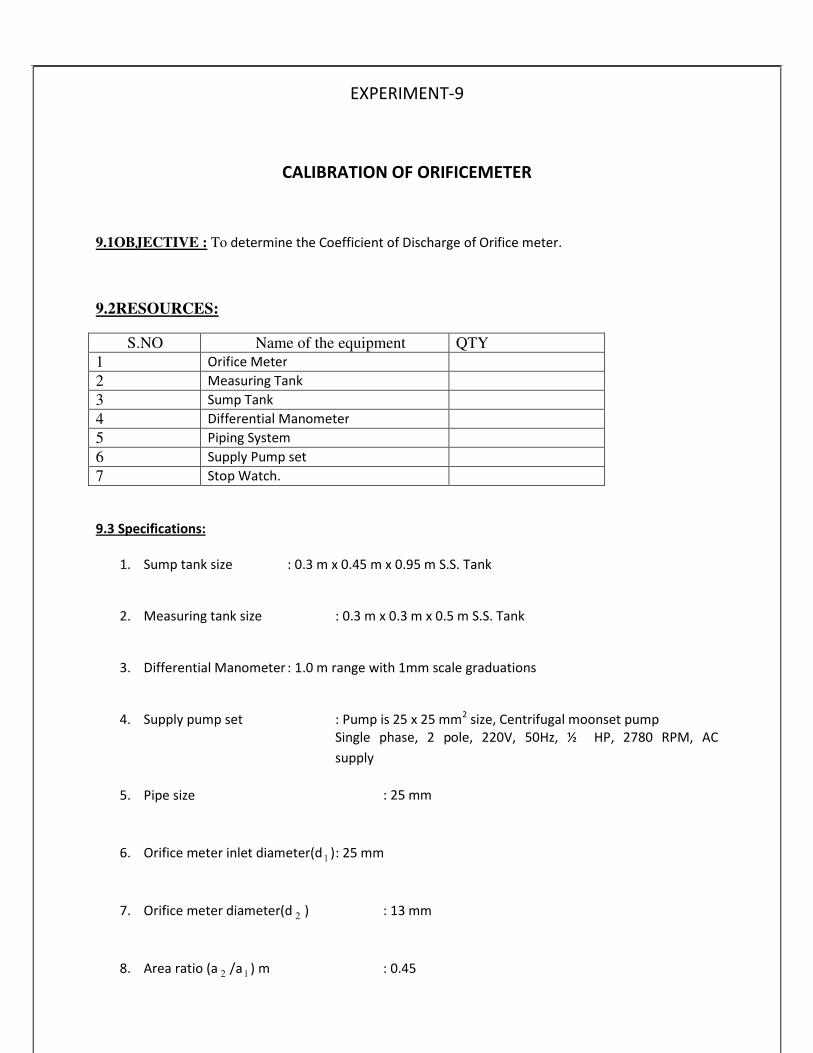
EXPERIMENT-9
CALIBRATION OF ORIFICEMETER
9.1OBJECTIVE : To determine the Coefficient of Discharge of Orifice meter.
9.2RESOURCES:
S.NO Name of the equipment QTY
1 Orifice Meter
2 Measuring Tank
3 Sump Tank
4 Differential Manometer
5 Piping System
6 Supply Pump set
7 Stop Watch.
9.3 Specifications:
1. Sump tank size
2. Measuring tank size
: 0.3 m x 0.45 m x 0.95 m S.S. Tank
: 0.3 m x 0.3 m x 0.5 m S.S. Tank
3. Differential Manometer : 1.0 m range with 1mm scale graduations
4. Supply pump set
5. Pipe size
: Pump is 25 x 25 mm2
size, Centrifugal moonset pump Single phase, 2 pole, 220V, 50Hz, ½ HP, 2780 RPM, AC
supply
: 25 mm
6. Orifice meter inlet diameter(d 1 ): 25 mm
7. Orifice meter diameter(d 2 ) : 13 mm
8. Area ratio (a 2 /a 1 ) m : 0.45

54
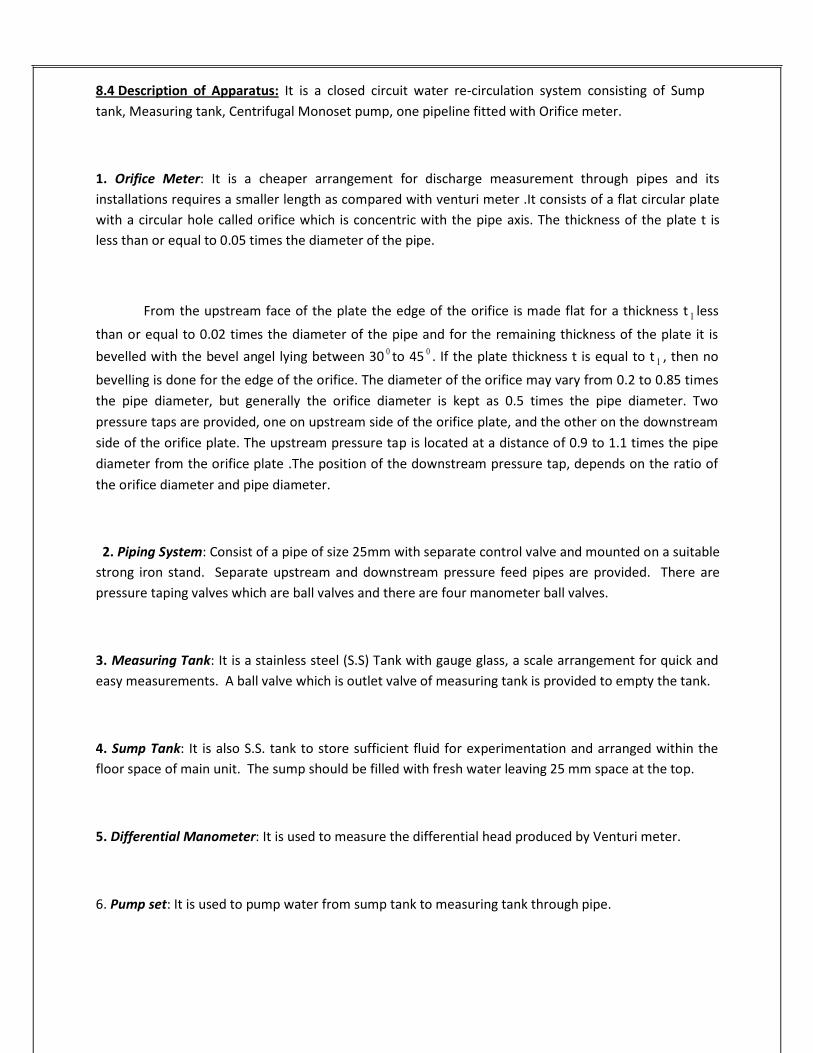
8.4 Description of Apparatus: It is a closed circuit water re-circulation system consisting of Sump
tank, Measuring tank, Centrifugal Monoset pump, one pipeline fitted with Orifice meter.
1. Orifice Meter: It is a cheaper arrangement for discharge measurement through pipes and its
installations requires a smaller length as compared with venturi meter .It consists of a flat circular plate
with a circular hole called orifice which is concentric with the pipe axis. The thickness of the plate t is
less than or equal to 0.05 times the diameter of the pipe.
From the upstream face of the plate the edge of the orifice is made flat for a thickness t 1 less
than or equal to 0.02 times the diameter of the pipe and for the remaining thickness of the plate it is
bevelled with the bevel angel lying between 300 to 45
0 . If the plate thickness t is equal to t 1 , then no
bevelling is done for the edge of the orifice. The diameter of the orifice may vary from 0.2 to 0.85 times
the pipe diameter, but generally the orifice diameter is kept as 0.5 times the pipe diameter. Two
pressure taps are provided, one on upstream side of the orifice plate, and the other on the downstream
side of the orifice plate. The upstream pressure tap is located at a distance of 0.9 to 1.1 times the pipe
diameter from the orifice plate .The position of the downstream pressure tap, depends on the ratio of
the orifice diameter and pipe diameter.
2. Piping System: Consist of a pipe of size 25mm with separate control valve and mounted on a suitable
strong iron stand. Separate upstream and downstream pressure feed pipes are provided. There are
pressure taping valves which are ball valves and there are four manometer ball valves.
3. Measuring Tank: It is a stainless steel (S.S) Tank with gauge glass, a scale arrangement for quick and
easy measurements. A ball valve which is outlet valve of measuring tank is provided to empty the tank.
4. Sump Tank: It is also S.S. tank to store sufficient fluid for experimentation and arranged within the
floor space of main unit. The sump should be filled with fresh water leaving 25 mm space at the top.
5. Differential Manometer: It is used to measure the differential head produced by Venturi meter.
6. Pump set: It is used to pump water from sump tank to measuring tank through pipe.

55
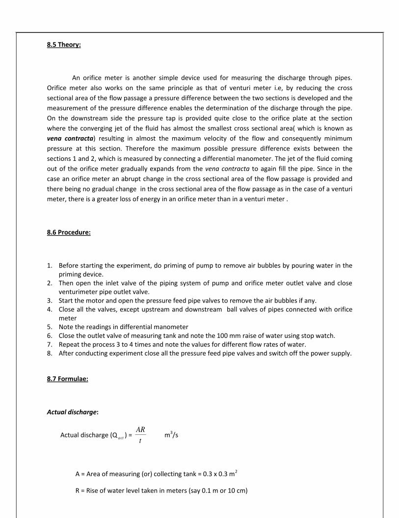
8.5 Theory:
An orifice meter is another simple device used for measuring the discharge through pipes.
Orifice meter also works on the same principle as that of venturi meter i.e, by reducing the cross
sectional area of the flow passage a pressure difference between the two sections is developed and the
measurement of the pressure difference enables the determination of the discharge through the pipe.
On the downstream side the pressure tap is provided quite close to the orifice plate at the section
where the converging jet of the fluid has almost the smallest cross sectional area( which is known as
vena contracta) resulting in almost the maximum velocity of the flow and consequently minimum
pressure at this section. Therefore the maximum possible pressure difference exists between the
sections 1 and 2, which is measured by connecting a differential manometer. The jet of the fluid coming
out of the orifice meter gradually expands from the vena contracta to again fill the pipe. Since in the
case an orifice meter an abrupt change in the cross sectional area of the flow passage is provided and
there being no gradual change in the cross sectional area of the flow passage as in the case of a venturi
meter, there is a greater loss of energy in an orifice meter than in a venturi meter .
8.6 Procedure:
1. Before starting the experiment, do priming of pump to remove air bubbles by pouring water in the
priming device. 2. Then open the inlet valve of the piping system of pump and orifice meter outlet valve and close
venturimeter pipe outlet valve. 3. Start the motor and open the pressure feed pipe valves to remove the air bubbles if any. 4. Close all the valves, except upstream and downstream ball valves of pipes connected with orifice
meter 5. Note the readings in differential manometer 6. Close the outlet valve of measuring tank and note the 100 mm raise of water using stop watch.
7. Repeat the process 3 to 4 times and note the values for different flow rates of water. 8. After conducting experiment close all the pressure feed pipe valves and switch off the power supply.
8.7 Formulae:
Actual discharge:
Actual discharge (Q act ) = AR
m3/s
A = Area of measuring (or) collecting tank = 0.3 x 0.3 m2
R = Rise of water level taken in meters (say 0.1 m or 10 cm)
t

56
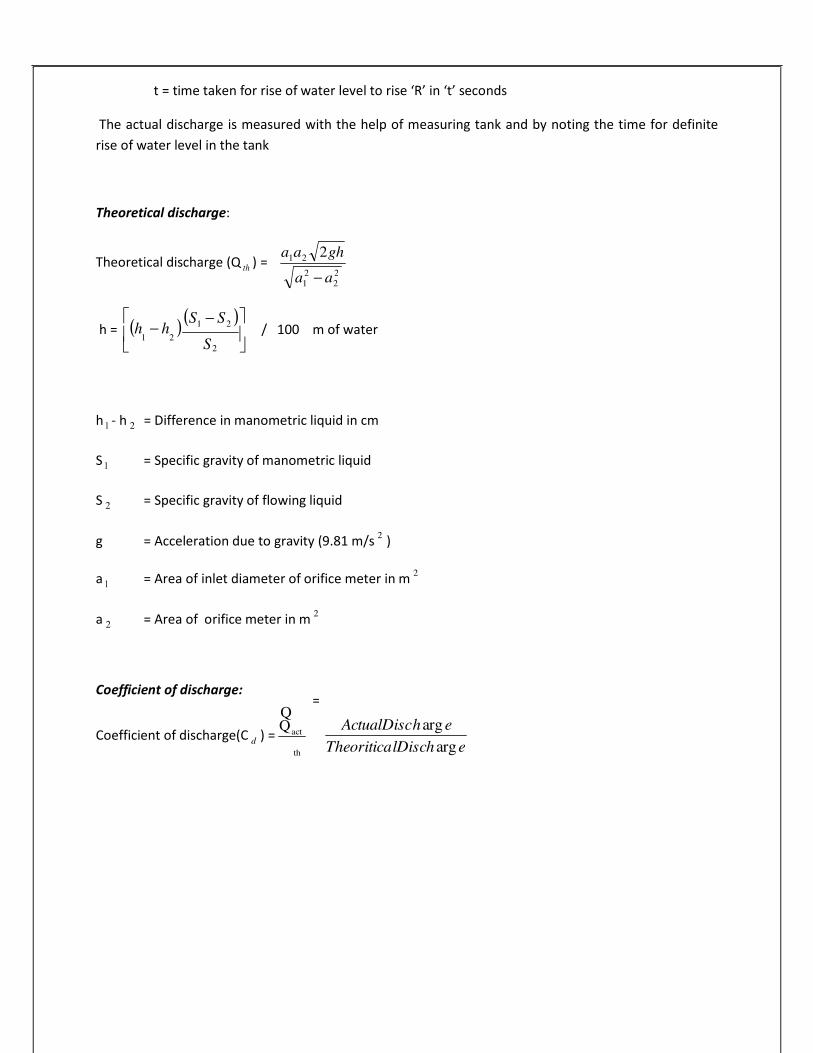
t = time taken for rise of water level to rise ‘R’ in ‘t’ seconds
The actual discharge is measured with the help of measuring tank and by noting the time for definite
rise of water level in the tank
Theoretical discharge:
Theoretical discharge (Q th ) = a1a2 2gh
a1 − a2
h = (h − h )
(S1 − S2 ) / 100 m of water
2
h 1 - h 2 = Difference in manometric liquid in cm
S 1 = Specific gravity of manometric liquid
S 2 = Specific gravity of flowing liquid
g = Acceleration due to gravity (9.81 m/s 2
)
a 1 = Area of inlet diameter of orifice meter in m 2
a 2 = Area of orifice meter in m 2
Coefficient of discharge:
Coefficient of discharge(C d ) = Q
act
th
ActualDischarg e
TheoriticalDischarge
Q=
2 2
1 2S

57
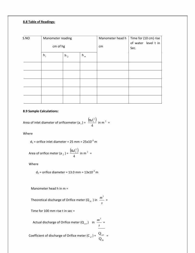
8.8 Table of Readings:
S.NO Manometer reading Manometer head h Time for (10 cm) rise
cm of hg cm
h 1 h 2 h m
of water level t in
Sec.
8.9 Sample Calculations:
Area of inlet diameter of orificemeter (a 1 ) = (
4
1 ) in m 2
=
Where
d1 = orifice inlet diameter = 25 mm = 25x10-3
m
Area of orifice meter (a 2 ) = (
4
2 ) in m 2
=
Where
d2 = orifice diameter = 13.0 mm = 13x10-3
m
Manometer head h in m =
3
Theoretical discharge of Orifice meter (Q th ) in s
=
Time for 100 mm rise t in sec =
3
Actual discharge of Orifice meter (Q act ) in s
=
Coefficient of discharge of Orifice meter (C d ) = Q
act
Qth
=
2dπ
2dπ
m
m

58
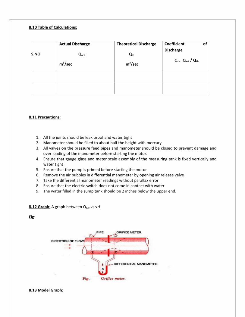
8.10 Table of Calculations:
Actual Discharge
S.NO Qact
m3/sec
Theoretical Discharge
Qth
m3/sec
Coefficient of
Discharge
Cd = Qact / Qth
8.11 Precautions:
1. All the joints should be leak proof and water tight 2. Manometer should be filled to about half the height with mercury 3. All valves on the pressure feed pipes and manometer should be closed to prevent damage and
over loading of the manometer before starting the motor. 4. Ensure that gauge glass and meter scale assembly of the measuring tank is fixed vertically and
water tight 5. Ensure that the pump is primed before starting the motor 6. Remove the air bubbles in differential manometer by opening air release valve
7. Take the differential manometer readings without parallax error 8. Ensure that the electric switch does not come in contact with water 9. The water filled in the sump tank should be 2 inches below the upper end.
8.12 Graph: A graph between Qact vs √H
Fig:
8.13 Model Graph:

59
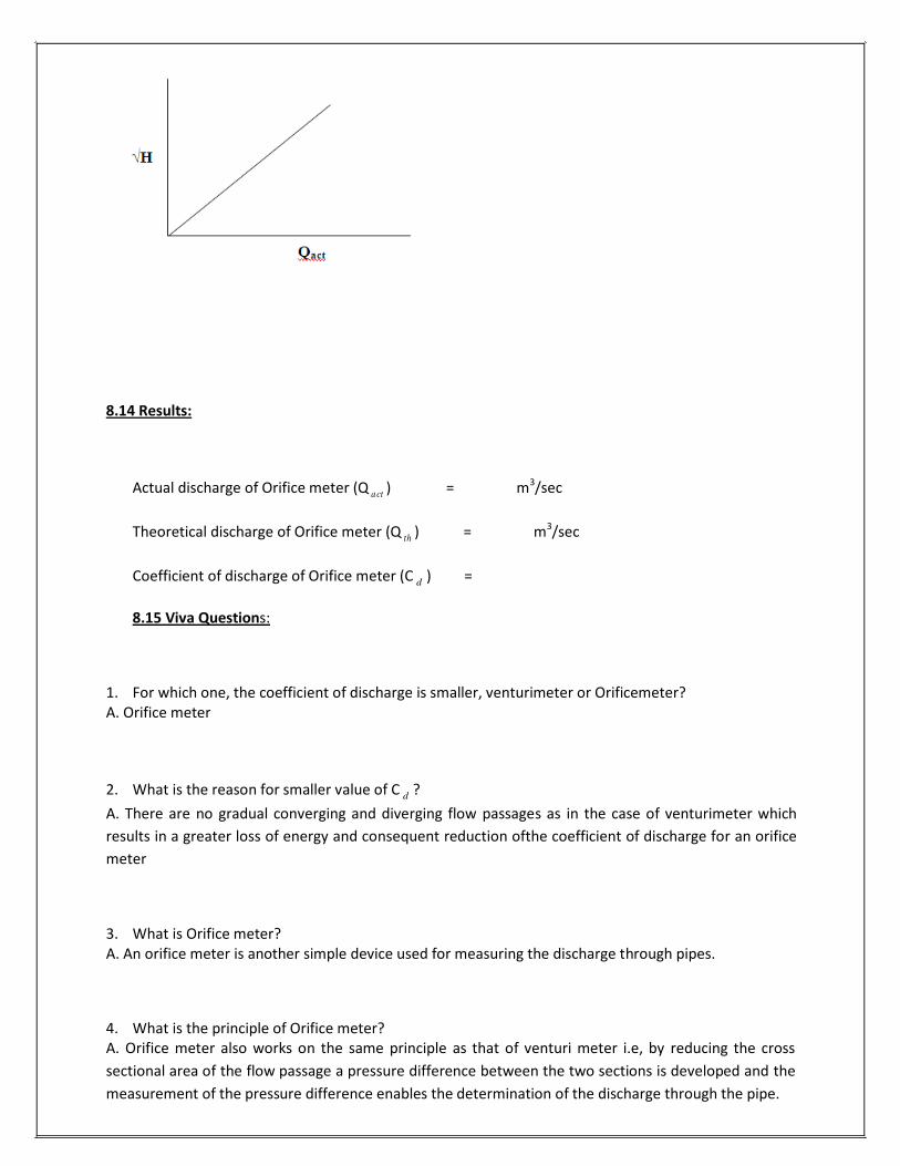
8.14 Results:
Actual discharge of Orifice meter (Q act ) = m3/sec
Theoretical discharge of Orifice meter (Q th ) = m3/sec
Coefficient of discharge of Orifice meter (C d ) =
8.15 Viva Questions:
1. For which one, the coefficient of discharge is smaller, venturimeter or Orificemeter?
A. Orifice meter
2. What is the reason for smaller value of C d ?
A. There are no gradual converging and diverging flow passages as in the case of venturimeter which
results in a greater loss of energy and consequent reduction ofthe coefficient of discharge for an orifice
meter
3. What is Orifice meter?
A. An orifice meter is another simple device used for measuring the discharge through pipes.
4. What is the principle of Orifice meter? A. Orifice meter also works on the same principle as that of venturi meter i.e, by reducing the cross
sectional area of the flow passage a pressure difference between the two sections is developed and the
measurement of the pressure difference enables the determination of the discharge through the pipe.

60
5. For discharge measurement through pipes which is having cheaper arrangement and whose
installation requires a smaller length? A. Orifice meter
6. What are the parts of Orifice meter?
A. Flat circular plate with a circular hole
7. What is the thickness of the plate t? A. t ≤ 0.05d where d= diameter of the pipe
8. What is the range of bevel angle in orifice meter?
A. 300
to 450
(preferably 450
)
9. What is the diameter of the orifice? A. It may vary from 0.2 to 0.85 times the pipe diameter, but generally the orifice diameter is kept as 0.5
times pipe diameter
10. Where two pressure taps are provided?
A. One on upstream side of the orifice plate and the other on downstream side of the orifice plate.
11. Where upstream pressure tap is located?
A. It is located at a distance of 0.9 to 1.1 times the pipe diameter from the orifice plate.
12. Which diameter is less, orifice or pipe?
A. Orifice meter
13. What is vena contracta?
A. Smallest cross sectional area
14. At which section on the downstream side the pressure tap is provided quite close to orifice plate? A. At the section where the converging jet of fluid has almost the smallest cross sectional area (which is
known as vena contracta)

61
15. Where the velocity of flow is maximum and pressure is minimum?
A. At vena contracta
16. Maximum possible pressure difference that exists between upstream side of the orifice plate and
downstream side of the orifice plate is measured by means of what? A. Differential manometer
17. Where there is a greater loss of energy, whether in venturi meter or in orifice meter?
A. In orifice meter
18. Why there is a greater loss of energy in orifice meter?
A. Because there is an abrupt change in the cross-sectional area of flow passage
19. What is value of c d ?
A. It is the range of 0.6 to 0.68
20. What is the manometer liquid?
A. Mercury
21. When an orifice is called large orifice? A. When head of liquid from the center of the orifice is less than 5 times the depth of orifice
22. On what the position of downstream pressure tap depends? A. It depends on the ratio of the orifice diameter and the pipe diameter.

62
EXPERIMENT-10
DETERMINATION OF FRICTION FACTOR FOR A GIVEN PIPE LINE 10.1 OBJECTIVE: To measure the frictional losses in pipes of different sizes.
10.2RESOURCES:
S.NO Name of the equipment QTY
1 Piping system
2 Sump Tank
3 Measuring Tank
4 Differential Manometer
5 Pump Set
6 Stop Watch
10.3 Specifications:
1. Sump tank size
2. Measuring Tank Size
: 0.95 m x 0.45 m x 0.3 m S.S. tank
: 0.3 m x 0.3m x 0.5 m S.S. Tank
3. Differential Manometer
4. No. of pipes
5. Piping system sizes
6. Pressure taping distance
7. Pump set
: 1 m range with 1mm scale of graduation
: 1S.S, 2 Galvanized Iron(GI) pipes
: 20 mm, 20mm, 12.7mm
: 0.1 m
: Pump is 25x25mm2
size, centrifugal, moonset
pump with single phase, 2pole, 220V, 1/2HP, 50
Hz, 2880 rpm, AC supply.

63
10.4 Description of apparatus:
1. Piping system: Consists of a set of 2G.I pipes and 1 S.S pipes of size 20mm, 12.7mm and 20mm and
length 1 m between pressure tapings with separate flow control valves. Separate upstream and
downstream pressure feed pipes are provided for the measurement of pressure heads with control
situated at common place for easy operation.
2. Sump tank: It is S.S. tank to store sufficient fluid for experimentation and arranged within the floor
space of main unit. The sump should be filled with fresh water having 25 mm space at the top.
3. Measuring tank: It is also a S.S tank with gauge glass, a scale arrangement for quick and easy
measurements. A ball valve which is outlet valve of measuring tank is provided to empty the tank.
4. Differential manometer: It is used to measure the differential head produced by piping system.
5. Pump set: It is used to pump water from sump tank to measuring tank through pipe. 10.5 Theory:
A pipe is a closed conduit which is used for carrying fluids under pressure. Pipes are commonly
circular section. As the pipes carry fluids under pressure, the pipes always run full.
The fluid flowing in a pipe is always subjected to resistance due to shear forces between fluid
particles and the boundary walls of the pipe and between the fluid particles themselves resulting from
the viscosity of the fluid. The resistance to the flow of fluid is, in general known as frictional resistance.
Since certain amount of energy possessed by the flowing fluid will be consumed in overcoming this
resistance to the flow, there will always be some loss of energy in the direction of flow, which however
depends on the type of flow, W.froude conducted a series of experiments to investigate frictional
resistance offered to the flowing water by different surfaces h f
= fLV
2
2gD
is Darcy Weisbach equation
Which is commonly used for computing the loss of head due to friction of pies. Here is f friction factor.
In order to determine the loss of head due to friction correctly, it is essential to estimate the value of the
factor f correctly when a fluid flows through a pipe, certain resistance is offered to the flowing fluid,
which results in causing a loss of energy. The various energy losses in pies may be classified as

64
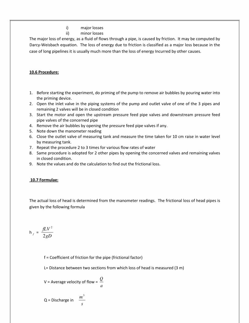
i) major losses
ii) minor losses The major loss of energy, as a fluid of flows through a pipe, is caused by friction. It may be computed by
Darcy-Weisbach equation. The loss of energy due to friction is classified as a major loss because in the
case of long pipelines it is usually much more than the loss of energy Incurred by other causes.
10.6 Procedure:
1. Before starting the experiment, do priming of the pump to remove air bubbles by pouring water into
the priming device. 2. Open the inlet valve in the piping systems of the pump and outlet valve of one of the 3 pipes and
remaining 2 valves will be in closed condition 3. Start the motor and open the upstream pressure feed pipe valves and downstream pressure feed
pipe valves of the concerned pipe 4. Remove the air bubbles by opening the pressure feed pipe valves if any.
5. Note down the manometer reading 6. Close the outlet valve of measuring tank and measure the time taken for 10 cm raise in water level
by measuring tank. 7. Repeat the procedure 2 to 3 times for various flow rates of water 8. Same procedure is adopted for 2 other pipes by opening the concerned valves and remaining valves
in closed condition. 9. Note the values and do the calculation to find out the frictional loss.
10.7 Formulae:
The actual loss of head is determined from the manometer readings. The frictional loss of head pipes is
given by the following formula
h f
= fLV
2
2gD
f = Coefficient of friction for the pipe (frictional factor)
L= Distance between two sections from which loss of head is measured (3 m)
V = Average velocity of flow = a
Q = Discharge in m
3
s
Q

65
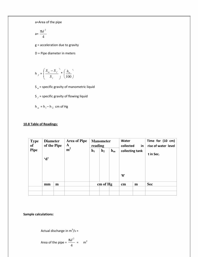
a=Area of the pipe
a= π
4
2
g = acceleration due to gravity
D = Pipe diameter in meters
h f
=
Sm
− Sf
* 100
S m = specific gravity of manometric liquid
S f
= specific gravity of flowing liquid
h m = h 1 – h 2 cm of Hg
10.8 Table of Readings:
Type
of
Pipe
Diameter
of the Pipe
‘d’
Area of Pipe A
m2
Manometer
reading
Water
collected in
collecting tank
‘R’
Time for (10 cm)
rise of water level
t in Sec.
h1
h2
hm
mm m cm of Hg cm m Sec
Sample calculations:
Actual discharge in m3/s =
Area of the pipe = π
4
2
= m2
d
fS
mh
d

66
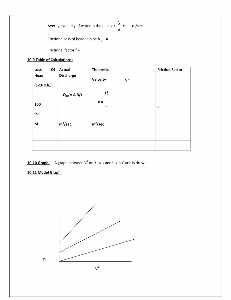
Average velocity of water in the pipe v = a
= m/sec
Frictional loss of head in pipe h
f =
Frictional factor f = 10.9 Table of Calculations:
Loss Of
Head
(12.6 x hm)
100
‘hf’
Actual
Discharge
Qact = A R/t
Theoretical
Velocity
V = a
V 2
Friction Factor
f
M
m
3/sec
m3/sec
10.10 Graph: A graph between V2
on X-axis and hf on Y-axis is drawn
10.11 Model Graph:
hf
V2
Q
Q

67
10.12 Precautions:
1. Ensure that the pump is primed before starting the motor
2. While doing the experiment on a particular pipe keep the other pipe line closed
3. Take the differential manometer readings without parallax error
4. Ensure that the electric switch does not come in contact with water
5. Remove air bubbles in differential manometer by opening air release valve
6. Ensure that opening and closing of manometer valves should be done carefully to avoid
leakage of mercury
7. Check that gauge glass and meter scale assembly of the measuring tank is fixed vertically
and water tight
8. Manometer should be filled to about half the height with mercury
9. Ensure that all valves on the pressure feed pipes and manometer should be closed to
prevent damage and over loading of the manometer
10. All the joints should be leak proof and water tight.
11. The water filled in the sump tank should be 2” below the upper end
10.13 Results:
Coefficient of loss of head h f
=
Friction factor f =
10.14 Viva Questions:
1. What is pipe?
A. A pipe is a closed circuit which is used for carrying fluids under pressure
2. The fluid flowing by a pie is always subjected to what? A. It is subjected to resistance due to shear forces between fluid particles and the boundary walls of the
pipe and between the fluid articles themselves resulting from the viscosity of the fluid
3. What is frictional resistance?
A. The resistance to the flow of fluid is frictional resistance.

68
4. In overcoming the frictional resistance what is consumed?
A. Certain amount of energy possessed by the flowing fluid will be consumed
5. What will be there in the direction of flow and it depends on what?
A. There will be some loss of energy in the direction of flow and depends on the type of flow.
6. What are the types of flow of fluid in a pipe?
A. Laminar, turbulent
7. On what the frictional resistance offered to the flow depends on?
A. Type of flow
8. What is Darcy-Weisbach equation?
A. h f
= fLV
2
2gD
9. What is the use of Darcy-Weisbach equation?
A. It is used for computing the loss of head due to friction in pipes
10. On what friction factor f depends upon? A. f is not a constant, but its value depends on the roughness condition of the pipe surface and the
Reynolds number of flow
11. Which is essential to determine the loss of head due to friction correctly?
A. Correct estimation of the value of the factor
12. In addition to Darcy-Weisbach equation what are the other formulae for head loss due to friction in
pipes? A. Chezy’s formula, Manning’s formula, Hazen-Williams formula

69
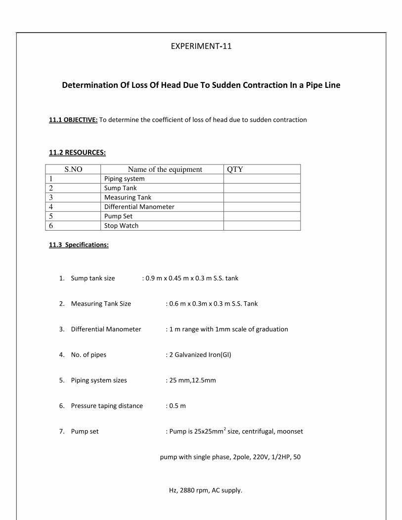
EXPERIMENT-11
Determination Of Loss Of Head Due To Sudden Contraction In a Pipe Line
11.1 OBJECTIVE: To determine the coefficient of loss of head due to sudden contraction
11.2 RESOURCES:
S.NO Name of the equipment QTY
1 Piping system
2 Sump Tank
3 Measuring Tank
4 Differential Manometer
5 Pump Set
6 Stop Watch
11.3 Specifications:
1. Sump tank size
2. Measuring Tank Size
: 0.9 m x 0.45 m x 0.3 m S.S. tank
: 0.6 m x 0.3m x 0.3 m S.S. Tank
3. Differential Manometer
4. No. of pipes
5. Piping system sizes
6. Pressure taping distance
7. Pump set
: 1 m range with 1mm scale of graduation
: 2 Galvanized Iron(GI)
: 25 mm,12.5mm
: 0.5 m
: Pump is 25x25mm2
size, centrifugal, moonset
pump with single phase, 2pole, 220V, 1/2HP, 50
Hz, 2880 rpm, AC supply.

70
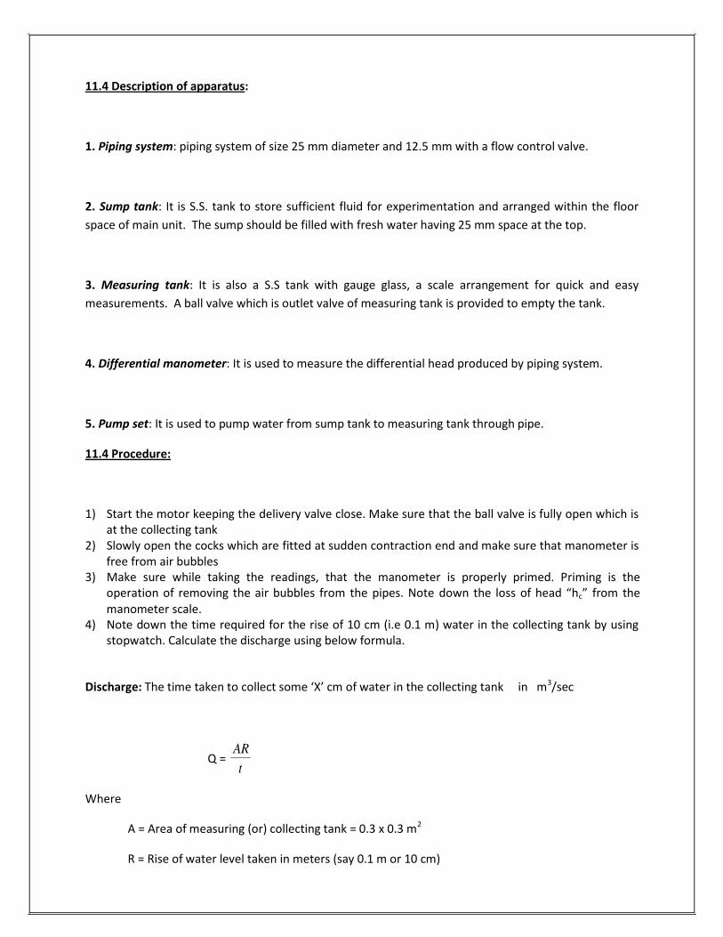
11.4 Description of apparatus:
1. Piping system: piping system of size 25 mm diameter and 12.5 mm with a flow control valve.
2. Sump tank: It is S.S. tank to store sufficient fluid for experimentation and arranged within the floor
space of main unit. The sump should be filled with fresh water having 25 mm space at the top.
3. Measuring tank: It is also a S.S tank with gauge glass, a scale arrangement for quick and easy
measurements. A ball valve which is outlet valve of measuring tank is provided to empty the tank.
4. Differential manometer: It is used to measure the differential head produced by piping system.
5. Pump set: It is used to pump water from sump tank to measuring tank through pipe. 11.4 Procedure:
1) Start the motor keeping the delivery valve close. Make sure that the ball valve is fully open which is
at the collecting tank 2) Slowly open the cocks which are fitted at sudden contraction end and make sure that manometer is
free from air bubbles 3) Make sure while taking the readings, that the manometer is properly primed. Priming is the
operation of removing the air bubbles from the pipes. Note down the loss of head “hc” from the
manometer scale. 4) Note down the time required for the rise of 10 cm (i.e 0.1 m) water in the collecting tank by using
stopwatch. Calculate the discharge using below formula.
Discharge: The time taken to collect some ‘X’ cm of water in the collecting tank in m3/sec
Q = AR
Where
A = Area of measuring (or) collecting tank = 0.3 x 0.3 m2
R = Rise of water level taken in meters (say 0.1 m or 10 cm)
t

71
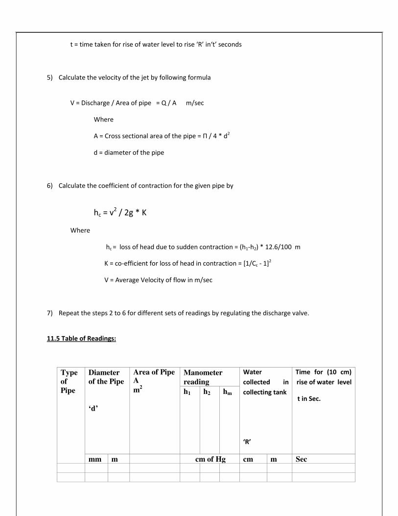
t = time taken for rise of water level to rise ‘R’ in‘t’ seconds
5) Calculate the velocity of the jet by following formula
V = Discharge / Area of pipe = Q / A m/sec
Where
A = Cross sectional area of the pipe = Π / 4 * d2
d = diameter of the pipe
6) Calculate the coefficient of contraction for the given pipe by
hc = v2
/ 2g * K
Where
hc = loss of head due to sudden contraction = (h1-h2) * 12.6/100 m
K = co-efficient for loss of head in contraction = [1/Cc - 1]2
V = Average Velocity of flow in m/sec
7) Repeat the steps 2 to 6 for different sets of readings by regulating the discharge valve.
11.5 Table of Readings:
Type
of
Pipe
Diameter
of the Pipe
‘d’
Area of Pipe A
m2
Manometer
reading
Water
collected in
collecting tank
‘R’
Time for (10 cm)
rise of water level
t in Sec.
h1
h2
hm
mm m cm of Hg cm m Sec

72
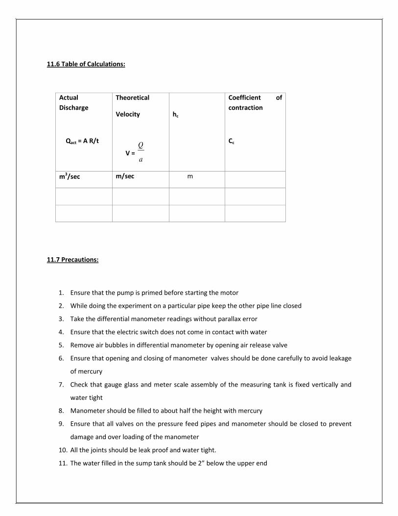
11.6 Table of Calculations:
Actual
Discharge
Qact = A R/t
Theoretical
Velocity
V = a
hc
Coefficient of
contraction
Cc
m3/sec
m/sec
m
11.7 Precautions:
1. Ensure that the pump is primed before starting the motor
2. While doing the experiment on a particular pipe keep the other pipe line closed
3. Take the differential manometer readings without parallax error
4. Ensure that the electric switch does not come in contact with water
5. Remove air bubbles in differential manometer by opening air release valve
6. Ensure that opening and closing of manometer valves should be done carefully to avoid leakage
of mercury
7. Check that gauge glass and meter scale assembly of the measuring tank is fixed vertically and
water tight
8. Manometer should be filled to about half the height with mercury
9. Ensure that all valves on the pressure feed pipes and manometer should be closed to prevent
damage and over loading of the manometer
10. All the joints should be leak proof and water tight.
11. The water filled in the sump tank should be 2” below the upper end
Q

73
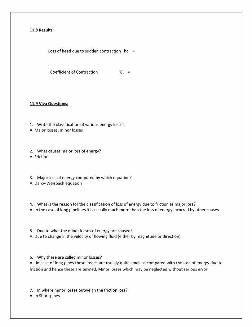
11.8 Results:
Loss of head due to sudden contraction hc =
Coefficient of Contraction Cc =
11.9 Viva Questions:
1. Write the classification of various energy losses.
A. Major losses, minor losses
2. What causes major loss of energy?
A. Friction
3. Major loss of energy computed by which equation?
A. Darcy-Weisbach equation
4. What is the reason for the classification of loss of energy due to friction as major loss?
A. In the case of long pipelines it is usually much more than the loss of energy incurred by other causes.
5. Due to what the minor losses of energy are caused?
A. Due to change in the velocity of flowing fluid (either by magnitude or direction)
6. Why these are called minor losses? A. In case of long pipes these losses are usually quite small as compared with the loss of energy due to
friction and hence these are termed. Minor losses which may be neglected without serious error.
7. In where minor losses outweigh the friction loss?
A. In Short pipes

74
8. Write some minor losses which may be caused due to the change of velocity.
A. Loss of energy due to sudden enlargement Loss of energy due to sudden contraction
Loss of energy at entrance to a pipe
Loss of energy at the exit from a pipe
Loss of energy due to gradual contraction or enlargement
Loss of energy in bends
Loss of energy in various pipe fit

75
EXPERIMENT-12
VERIFICATION OF BERNOULLI’S EQUATION
12.1 OBJECTIVE: To prove that the total head at any point along the flow is same i.e, datum head +
pressure head + velocity head is constant along the flow
Or
2 2
w +
2g +z1 =
w +
2g +z2
12.2RESOURCES:
S.NO Name of the equipment QTY
1 Bernoulli’s apparatus which consists
of supply and receiving chambers
with scales and glass tubes
2 Piezometer glass tubes
3 Measuring tank (collecting tank)
4 Differential Manometer
5 Supply pump set
6 Stop Watch
12.3 Specifications:
1. Sump tank size : 1.25 m x 0.3m x 0.3m S.S. tank
2. Measuring Tank size
3. Pump size
4. Supply pump set
: 0.3 m x 0.5 m
: 25mm x 25 mm
: Pump is centrifugal manometer pump with single phase, 2
pole, 220V, 50 Hz, ½ Hp, 2880 RPM, AC supply
12.4 Description of apparatus:
There are supply and receiving chambers and interlinking experimental sides made out of perspex
sheets for the purpose of observing the flow. The interlinking duct is smoothly varying in cross section
so that the velocity of flow changes gradually for the purpose of experiments with minimum friction loss
76
p pv v1 21 2
and loss due to turbulence. Piezometer glass tubes are provided at suitable intervals along the duct for
the measurement of pressure head at various points. A flow control valve is provided at the exit of the
receiving chamber for adjusting and keeping different flow rates through the apparatus. A collecting
tank (receiving chamber) is provided for the measurement of rate of flow. The apparatus is kept in the
spirit level position horizontally by means of adjusting the screw arrangement provided at the bottom of
the sump.
Measuring Tank: It is a stainless steel (S.S) Tank with gauge glass, a scale arrangement for quick and easy
measurements. A ball valve which is outlet valve of measuring tank is provided to empty the tank.
Sump Tank: It is also S.S. tank to store sufficient fluid for experimentation and arranged within the floor
space of main unit. The sump should be filled with fresh water leaving 25 mm space at the top.
Pump set: It is used to pump water from sump tank to measuring tank through pipe. 12.5 Theory:
The Bernoullis equation is
2
w +
2g +z = c
Which is applicable for steady, irrotational flow of incompressible fluids
P= pressure
W= ρ g=specificweight
V= velocity at any point
g=gravitational acceleration
ρ = mass density
w = pressure head or static head
p v
p

77
2
2g = velocity head or kinetic head
Z = potential head or datum head
C= arbitrary constant
The sum of pressure head, velocity head and the potential head is known as the total head or the total
energy per unit weight of the fluid. Bernoullis equation states that in a steady irrotational flow of an
incompressible fluid the total energy at any point is constant.
If Bernoulli’s equation is applied between any two points in a steady irrotational flow of an
incompressible fluid, then we get
2 2
w +
2g +z1 =
w +
2g +z2
Where the different terms with subscripts and 2 correspond to the two points considered.
The sum of the pressure head and the potential head ( w
+ z ) is termed as piezometric head.
Each term represent the energy permit weight of the flowing fluid. The energy per unit weight of the
fluid is expressed as N.m/N that is, it has a dimension of length and therefore it is known as head.
v
p pv v1 21 2
p

78
12.6 Procedure:
1. Before starting the experiment, do priming of the pump to remove the air bubbles.
2. Open the inlet valve of the piping system of the pump. 3. Open the outlet valve of the piezometer tube. 4. Start the motor and keep the water level constant in the supply tank by operating various
valves. 5. Then note down the pressure head from the piezometer scale directly 6. Close the outlet valve of the mercury tank and note down the time for 100 mm raise of water
level note down the valves for pressure head, velocity head for different areas of piezometer
and calculate the total head.
12.7 Formulae:
Actual discharge:
Actual discharge (m3 /s) = Q act =
AR m
3/S
A= Area of measuring tank = 0.3 x 0.3m2
R = Difference in levels of water in measuring tank in m
T = time in seconds
Velocity = Q/a
a= cross sectional area of duct at various intervals
Total Head:
2
w +
2g +z = c
p
w
= Piezometer reading pressure head
2
2g = velocity head
Z = datum head
t
p v
v

79
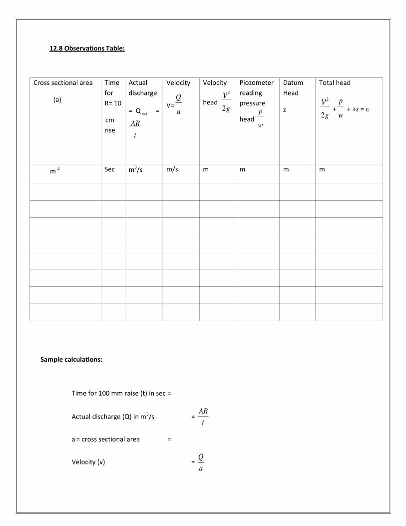
12.8 Observations Table:
Cross sectional area
(a)
Time
for
R= 10
cm
rise
Actual
discharge
= Q act =
AR
t
Velocity
V= a
Velocity
2
head 2g
Piozometer
reading
pressure
head w
Datum
Head
z
Total head
2
2g +
w + +z = c
m 2
Sec
m3/s
m/s
m
m
m
m
Sample calculations:
Time for 100 mm raise (t) in sec =
Actual discharge (Q) in m3/s =
AR
a = cross sectional area =
Velocity (v) = a
Q v
pv p
t
Q

80
2
Velocity head = 2g
=
Piezometer reading pressure head w
=
Datum head (z) =
2
Total head = w
+ 2g
+ z = c
12.9 Precautions:
1. Be careful to avoid leakage of the piezometer tubes
2. The water filled in the sump tank should be 2 inches below the upper end
3. Ensure that the electric switch does not come in contact with water
4. Ensure that the water level is constant in the supply tank during the experiment
5. Check that the gauge glass and meter scale assembly of the measuring tank is fixed vertically
and water tight.
6. Ensure that the pump is primed before starting the motor.
7. All joints should be leak proof and water tight
12.10 Result:
The total head at any point along the flow is same.
V
p
p v

81
12.11 Viva Questions:
1. What is Bernoulli’s equation? 2
A. w
+ 2g
+z = Constant
2. What is w
?
A. Pressure energy per unit weight of fluid or pressure head or static head.
2
3. What is 2g
?
A. Kinetic energy per unit weight or kinetic head or velocity head
4. What is z?
A. Potential energy per unit weight or potential head or datum head
5. What are the assumptions of Bernoulli’s equation?
A. 1) The fluid is ideal (i.e, viscosity is zero) 2) The flow is steady
3) The flow is incompressible
4) The flow is irrotational
6. What Bernoulli’s equation states? A. It states that in a steady, ideal, irrotational flow of an incompressible fluid, the total energy at any
point of the fluid in constant
7. For which type of fluids Bernoulli’s equation is applicable?
A. For steady, irrotational flow of incompressible fluids
8. What is total head?
A. Sum of pressure head, velocity head, and potential head is known as total head
p v
p
v

82
9. If Bernoulli’s equation is applicable between two points what is the equation of Bernoulli? 2 2
A. w
+ 2g
+z1 = w
+ 2g
+z2
10. What is Piezometric head?
A. Sum of pressure head and potential head
11. In Bernoulli’s equation each term represents what? A. The energy per unit weight of the flowing fluid.
12. Why each term is called head?
A. The energy per unit weight of the fluid is expressed as Nm/N that is it has a dimension of length and
therefore it is known as head
13. What is viscosity?
A. It is the property of fluid which offers resistance to the movement of one layer of fluid over another
adjacent layer of fluid.
p1p2
v v1 2

83