Mechanical Engineering Design II
41
Mechanical Engineering Design II Ninth & Tenth Lectures Decision Making
Transcript of Mechanical Engineering Design II

Mechanical Engineering Design II
Ninth & Tenth Lectures
Decision Making

Portable Chair
Problems of Existing Design:
Bending of holding frame

Broken small table

Paper is used to eliminate the shaking of the small table

We used brainstorming method to generate as much idea as possible. It is the most common method used for generating ideas.
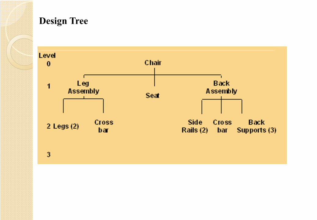
Design Tree
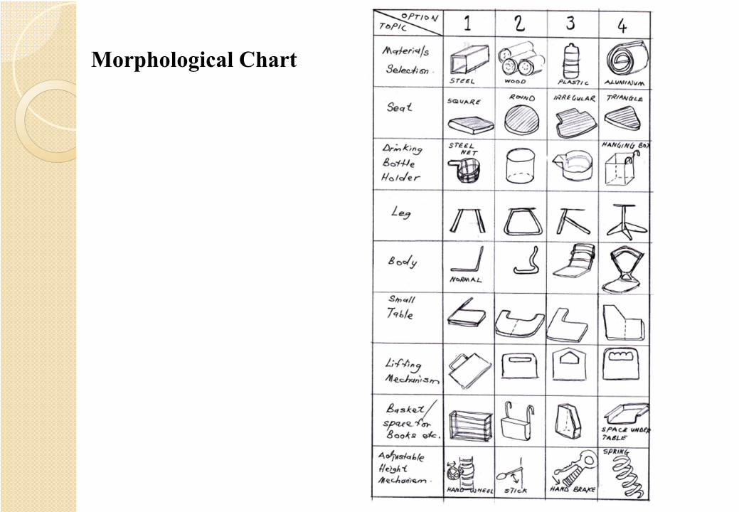
Morphological Chart

Example1. Vibration Motor

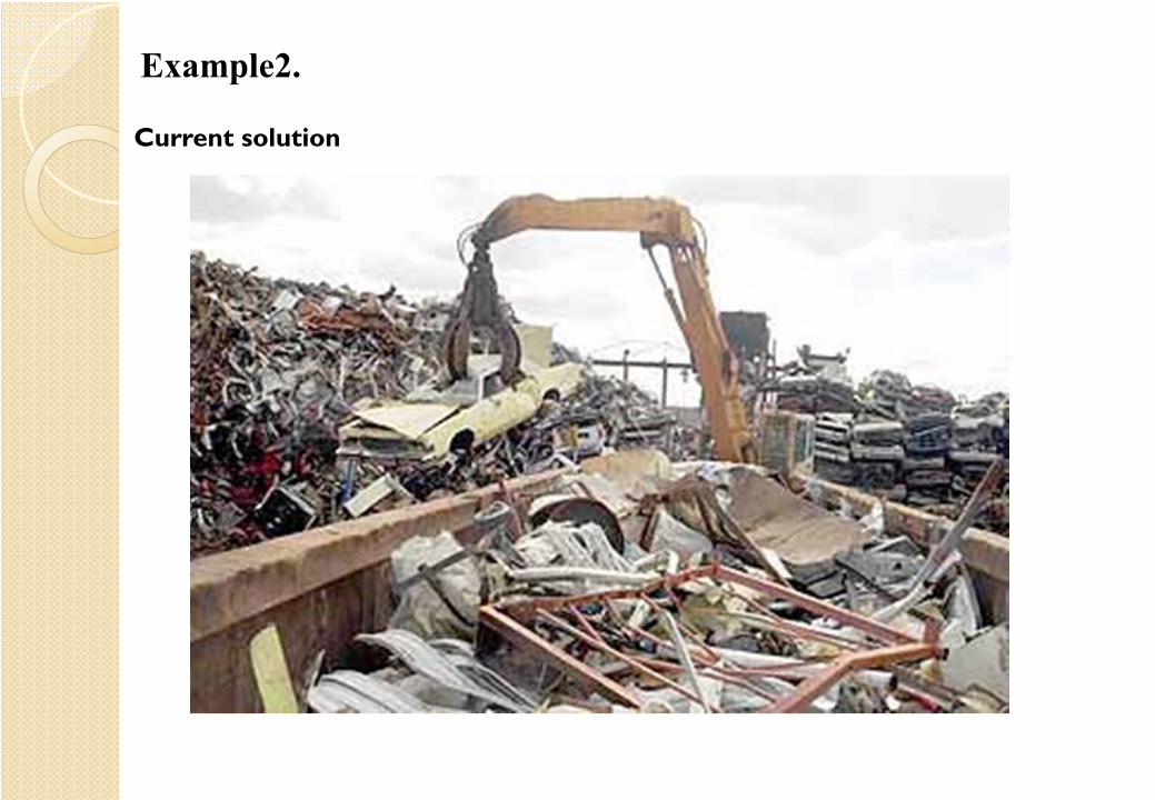
Example2.
Current solution
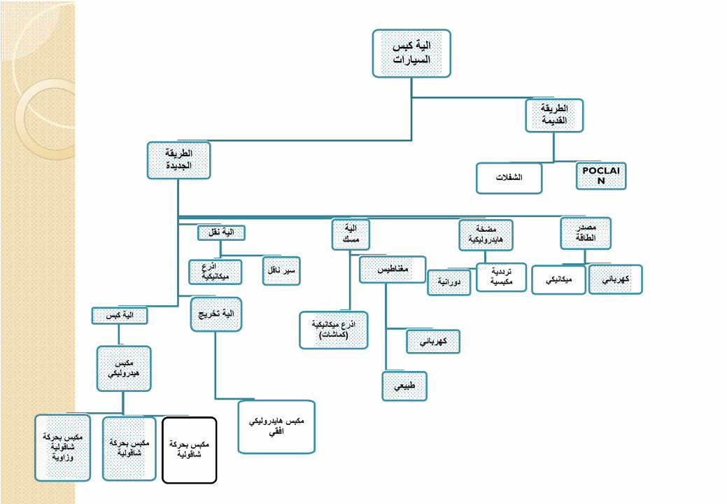
الية كبس السيارات
الطريقة الجديدة
الية تخريج
مكبس ھايدروليكي افقي
الية كبس
مكبس ھيدروليكي
مكبس بحركة شاقولية وزاوية
مكبس بحركة شاقولية
مكبس بحركة شاقولية
الية نقل
اذرع ميكانيكية سير ناقل
الية مسك
اذرع ميكانيكية )كماشات(
مغناطيس
كھربائي
طبيعي
مضخة ھايدروليكية
دورانيةترددية مكبسية
مصدر الطاقة
ميكانيكيكھربائي
الطريقة القديمة
الشفلاتPOCLAI
N

Final Design


Example3.
Current solutions

إلية المسك(A1)
نظام السيطرة
نظام التحريك
الھيكل نظام الرفع
الحاملة الية المسك
إلية المسك(A2)
إلية المسك(A3)
إلية المسك(A4)
ھيدروليكية
الحاملة(B4)
الحاملة(B3)
الحاملة(B2)
الحاملة(B1)
يدوية
الھواء المضغوط
الھيكل(D3)
الھيكل(D2)
الھيكل(D1)
التروسلاسلكي كھربائي
يدوي
نقل القدرة
الحزام سلكي
السلاسل
الكھربائي


Decision Making
Simple comparison By weightingBy mathematical
analysis and probability
one is better orworse than theother.
put them in orderof performance .
its very rare indesign.
Weighting Chart or Emphasis Curve
Σ GW Method
The Decision Network
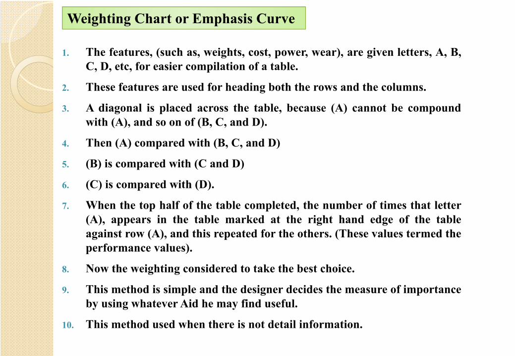
1. The features, (such as, weights, cost, power, wear), are given letters, A, B,C, D, etc, for easier compilation of a table.
2. These features are used for heading both the rows and the columns.
3. A diagonal is placed across the table, because (A) cannot be compoundwith (A), and so on of (B, C, and D).
4. Then (A) compared with (B, C, and D)
5. (B) is compared with (C and D)
6. (C) is compared with (D).
7. When the top half of the table completed, the number of times that letter(A), appears in the table marked at the right hand edge of the tableagainst row (A), and this repeated for the others. (These values termed theperformance values).
8. Now the weighting considered to take the best choice.
9. This method is simple and the designer decides the measure of importanceby using whatever Aid he may find useful.
10. This method used when there is not detail information.
Weighting Chart or Emphasis Curve

Order of preference
Alternatives
B D C
BDC
D CD
Alternatives

1. At the bottom of the table, we now have a measure of performance
of the different designs when considered in relation to the chosen
feature.
2. When the values at the bottom of the table differs by about 10%,
then they should be considered to be equal at this stage, that’s
mean, the accurate of this method is about 90%.
3. The disadvantages of this method lie in difficulty in making the
initial weighting decisions.
4. The other difficulty lies in the choice of features that will be
considered in order to obtain a measure of performance.
Σ GW Method
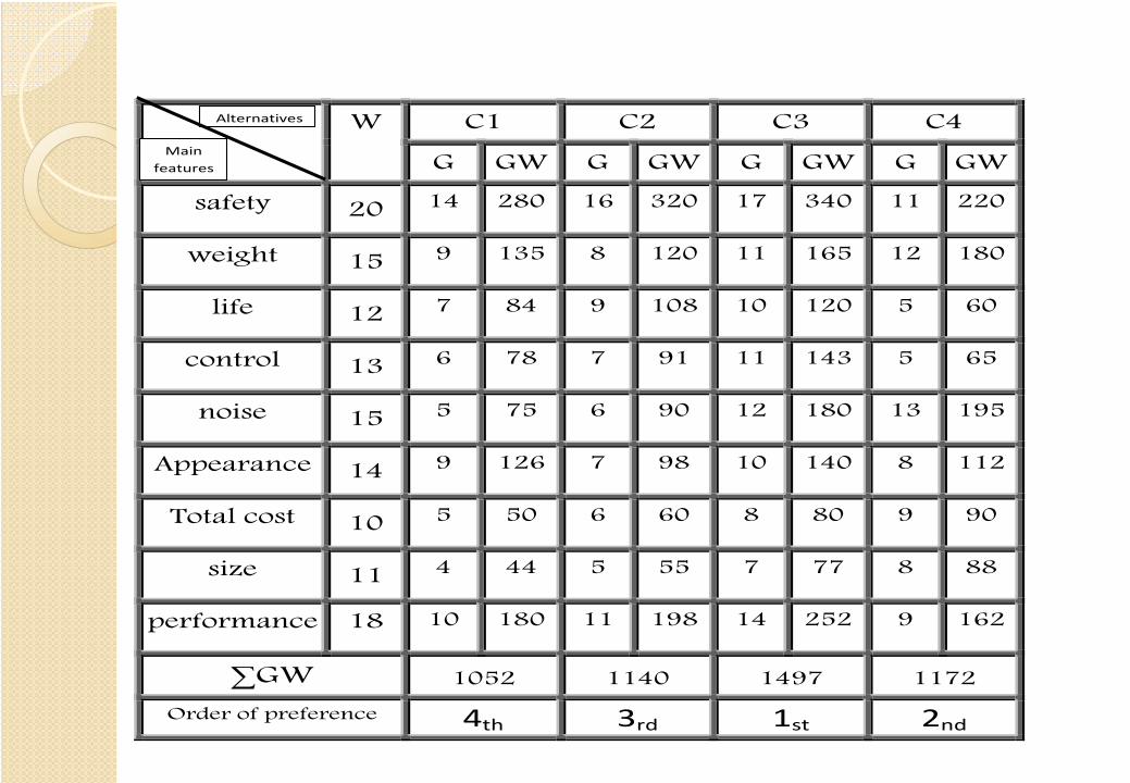
W C1 C2 C3 C4
G GW G GW G GW G GW
safety 20 14 280 16 320 17 340 11 220
weight 15 9 135 8 120 11 165 12 180
life 12 7 84 9 108 10 120 5 60
control 13 6 78 7 91 11 143 5 65
noise 15 5 75 6 90 12 180 13 195
Appearance 14 9 126 7 98 10 140 8 112
Total cost 10 5 50 6 60 8 80 9 90
size 11 4 44 5 55 7 77 8 88
performance 18 10 180 11 198 14 252 9 162
∑GW 1052 1140 1497 1172
Order of preference 4th 3rd 1st 2nd
Alternatives
Main features

1. This method involves a little from each of the methods above.
2. It is difficult to use, but it worth the effort.
3. The example below clarifies this method.
4. After doing the example, trace the parts from top to the bottom of the
decision network.
5. Find the measure of performance.
The Decision Network


Mechanical Engineering Design II
Eleventh & Twelfth Lectures
• Production of system specification• Production of system scheme• Feasibility Study


Power Transmission Problem
Alte
rnat
ive
solu
tions
?

Analysis
Analysis
Analysis
Analysis
Decision making according to
criteria
Best solution
General Layout

Pro
duct
ion
of s
yste
m s
peci
ficat
ion
Pro
duct
ion
of s
yste
m s
chem
e
Det
ail D
raw
ing
Ass
embl
y D
raw
ing
Final design

Assembly Drawing

Sub-Assembly Drawing

Detail Drawing

The Feasibility Study
(Design Acceptance or Design Practicality)
• The words “the feasibility study” are used to describe the analysis of the design which
attempts to take into account all relevant facts. The outcome of the feasibility study is
a major factor in the decision to continue with the design.
• It is not suggested that feasibility checking cannot begin until the system scheme and
system specification are produced however, since this is the first point in the design
process where the indicate the final form of the system, it is the most logical point at
which to check that the system can be made economically and will perform
reasonably well in the desired manner. (Any study carried out at an earlier stage
could be termed a Plausibility Study).

During the feasibility study, the following points should be checked:1. Is the system compatible with the basic physical laws? (Mainly conservation laws).2. Is the system compatible as whole with its environment? In those cases where compatibility is
relevant, are all parts of the system compatible with each other, and with adjacent parts of theenvironment?
3. Is the system economically feasible from the manufacturer’s points of view?4. Is the system feasible as regards its market?5. Are all the properties of the system acceptable with the terms of the original design specification?
Consider the follow-up of properties not mentioned in the design specification.6. Is this particular design no better than previous existing designs? Compare and contrast. Consider
the cost of covering features which are additional to those on existing equipment.7. will the time taken to manufacture – test – develop and transport be reasonable? Critical path
analysis can be used to highlight difficult regions.8. Does the design demand new manufacturing techniques within the manufacturer’s organization, or
does the design demand completely new manufacturing techniques to make it economicallyfeasible?
9. Is the system considered to be reliable enough for successful operation, or should special provisionsbe made to improve reliability.
10. Can the system be readily maintained, or is the design such that the minimum of maintenance isrequired?
11. Is the system legally saleable? Have any patent rights been violated?

Mechanical Engineering Design II
Thirteenth Lecture
Design-Reliability and Failure
Design-Reliability and Failure
Failure of a design when in service costs money for replacement, and often the failure
itself causes other financial looses. On the other hand, to design so that the chance of
failure is very remote also costs money.
It can therefore be seen that the designer should consider failure of the design. The
optimum design should be a compromise, that is, it is optimum only for the particular
criteria relevant to that design.
It is known that a considerable amount of mechanical design is associated with very
small quantities, and in a number of cases only one system is manufactured. In most
designs the only items of equipment in frequent use are nuts and bolts. For this reason
statistical methods which are often used to analyze failure and improve reliability are
only of use in specialized mechanical engineering design, such as mass-produced car
design.

The mechanical engineer has devised a number of methods to overcome the problem of lackof numbers, some of which will be mentioned here. These methods are also used by otherdesigners, often in addition to statistical methods.
1. To make systems more reliable, use accurate methods of design analysis coupled withrealistic assessment of loads.
e.g. (a) Use adequate checking procedures.(b) Use more accurate thick cylinder theory rather than the simpler and quicker theory in
relevant cases.(c) Use fatigue theory rather than arbitrary factors when considering cyclic loads.(d) Assess loads realistically by dynamic analysis and careful thought rather than by
arbitrary load factors.2. If difficulty is encountered in putting note.1 into practice, then use generous reserve factors
to take account of ignorance. Make use of rerating, (i.e. working at much reduced stresslevels).
3. Remember that evolutionary design is in general more reliable than revolutionary design.4. Make the design as simple as possible. The less parts there are in a piece of equipment, then
the less chances of failure there are.

5. Use standard parts and materials of known and proven reliability.6. Use British Standards. Also, use any other engineering standards and Codes of Practice
which are known to improve reliability.7. Build in redundancy (here interpreted in the same way as redundancy in beam analysis) and
analyze as though the redundancy were missing. This is very similar to note.2 above, but itcan be dangerous to use this method without considerable experience.
8. Design so that if one very important part should fail and give a catastrophic result, thenanother part or system takes over temporarily. It is better if the second system operates on adifferent principle to the first. Repair is executed as soon as possible.
9. Design to take overloads on the system by designing so that they cause visible distortion, butnot catastrophic failure. Repair is executed as soon as possible.
10. If further functioning would be likely to cause damage to the system or its surroundings,incorporate devices or design features into the system so that failure causes the system tostop functioning. Take care that the sudden cessation of functioning does not itself causetroubles. Repair is executed as soon as possible.
11. Use composite structures so that failure of any one part, or a few parts, does not causecomplete failure. Repair is executed as soon as possible.
12. Include devices that relieve the overload, but allow normal use to continue.

13. Incorporate devices or design features so that incorrect assembly and use is preferablyimpossible. If incorrect assembly is possible, then there should be features which preventnormal operation.
14. Incorporate warning devices so that malfunctioning is obvious. Make warning devices sothat the malfunctioning of the warning device itself is obvious.
15. Prepare adequate test specifications to ensure desired reliability.16. Although it is included under the heading of note.6, ensure that electrochemical corrosion
possibilities are adequately studied.17. Consider special features relating to human safety if failure should occur.18. Supply adequate information to all persons directly or remotely concerned with the
equipment.19. Set up adequate lines of communications and records to record and collate all information
relating to failures.
Certain of the notes above also relate to (failsafe design), that is the design of equipmentthat will revert to a safe condition if a failure should occur.