MECHANICAL Catalog 2013 - Grinnell.hu - Grinnell hornyos ... · 125 139.7 51.7 79.26 4.8 178.3...
22
GROOVED COUPLINGS 17
Transcript of MECHANICAL Catalog 2013 - Grinnell.hu - Grinnell hornyos ... · 125 139.7 51.7 79.26 4.8 178.3...

GROOVED
COUPLINGS
17

www.grinnell.com
GROOVED COUPLINGS
Grooved
Couplings
GRINNELL reserves the right to change the contents without notice.18
GRINNELL Couplings are designed for grooved end pipe and are available in nominal sizes of 25 to 600mm (1" to 24") including BS, ISO, and JIS outside diameters.
The GRINNELL Coupling Design provides economical advantages when compared to welded or flanged systems. GRINNELL Couplings provide a universal method for connecting pipe, fittings, and pipe system components.
GRINNELL Couplings and Gaskets permit a wide selection of combinations for specific applications.
Field modifications are easily accommodated with GRINNELL Mechanical Products as the couplings can be easily rotated, eliminated and/or added to facilitate necessary modifications.
Grooved Couplings Table of Contents
General notes: Additional information is included in our data sheets and is available upon request. It is the Designer’s responsibility to select products suitable for the intended service and to ensure that pressure ratings and performance data is not exceeded. Always read and understand the installation constructions. Never remove any piping components nor correct or modify any piping deficiencies without first depressurizing and draining the system. Material and gasket selection should be verified with the gasket recommendation listing for the specific application.
Figure 772
Rigid Couplings
Pages 20 - 21
Figure 740
Rapid Installation Pivot-Bolt (GRIP) Rigid Couplings
Page 22
Figure 774
Rigid Couplings
Page 23
Figure 705
Flexible Couplings
Page 24
Figure 770
High Pressure Rigid Couplings
Page 25
Figure 707
Heavy Duty Flexible Couplings
Pages 26 - 27
Figure 707L
Large Diameter Couplings
Page 28
Figure 7707 N
Large Diameter Flexible Couplings
Page 29
Figure 909
Plain End Couplings
Page 30
Figure 780
Grooved Snap Couplings
Page 31
Figure XH-70EP
Extra Heavy Rigid Couplings With End Protection (EP) Gasket
Pages 32 & 171
Figure 716
Flexible Reducing Couplings
Page 33
Figure 702
Mechanical Outlet Couplings
Pages 34 - 35
Figure 7706-T
Transition Couplings
Page 36
Electrical Continuity
Page 37

Refer to back cover for country-specific contact information
GROOVED COUPLINGS
Grooved
Couplings
19
Full contact between Figure 772 Coupling key and groove diameter
Ductile Iron Housing Specifications
castings, Grade 65-45-12
(65,000 psi)
(45,000 psi)
galvanizing
Bolt/Nut Specifications
Metric: Carbon steel oval neck track head bolts (Gold colour coded) are heat treated and conform to the physical properties of ASTM F 568M with a minimum tensile strength of 760 MPa. Carbon Steel heavy hex nuts conform to the physical properties of ASTM A 563 M Class 9. Bolts and nuts are zinc-electroplated conforming to ASTM B 633.
ANSI: Carbon steel oval neck bolts and nuts are heat-treated and conform to the physical properties of ASTM A 183 Grade 2 and SAE J429 Grade 5 with a minimum tensile strength of 7584 Bar (110,000 psi). Carbon Steel heavy hex nuts conform to the physical properties of ASTM A 183 Grade 2 and SAE J995 Grade 5. Bolts and nuts are zinc-electroplated conforming to ASTM B 633.
request.
Coatings
GRINNELL Coupling Gasket Specifications
gaskets have a Green colour code stripe identification and conform to ASTM D 2000 for service temperatures from -34°C to 110°C ( -30°F to 230°F). They are recommended for hot water not to exceed 110°C (230°F), plus a variety of dilute acids, oil free air, and many chemical services. They are not recommended for petroleum services. For low temperature and vacuum systems, a Tri-Seal Grade “E” EPDM gasket with a rigid coupling is recommended.
gaskets have an Orange colour code stripe identification and conform to ASTM D 2000 for service temperatures from -29°C to 82°C ( -20°F to 180°F). They are recommended for petroleum products, vegetable oils, mineral oils, and air with oil vapors.
gaskets are Red colour code stripe and conform to ASTM D 2000 for service temperatures from -34°C to 177°C ( -30°F to 350°F). They are recommended for air without hydrocarbons, or dry heat.
gaskets have a Blue colour code stripe and conform to ASTM D 2000 for service temperatures from -7°C to 149°C (+20°F to 300°F). They are recommended for oxidizing acids, petroleum products, hydraulic fluids, lubricants, and halogenated hyrdrocarbons.
gaskets have a Yellow and Green colour code stripe and are for potable water systems up to 82°C (180°F). They are not recommended for petroleum service.
NSF-61 Certified centre-stop, push-on style gaskets have a Green and Red colour code stripe. For closed-loop heating systems from -34°C to 120°C (-30°F to 250°F) and potable water systems up to 82°C (up to 180°F). Recommended for use in low temperature and vacuum systems. They are not recommended for petroleum service.
MATERIAL SPECIFICATIONS
Additional Features:
special tools.
Limited Warranty, except for G-MINE which is 6 months. Review terms and conditions of sale on www.grinnell.com.
* Shurjoint product specifications can be found at www.shurjoint.com

www.grinnell.com
GROOVED COUPLINGS
Grooved
Couplings
GRINNELL reserves the right to change the contents without notice.20
Figure 772 Rigid Couplings(Page 1 of 2)
Tech Data Sheet: G141The GRINNELL Figure 772 Rigid Coupling provides a rigid joint by firmly gripping along the full 360° circumference of the pipe grooves. This coupling offers a dependable method of joining pipe and is an economical alternative to welding, threading, or using flanges. The GRINNELL Figure 772 Rigid Coupling is UL Listed for grounding and bonding, and is suitable for bonding systems with a maximum service entrance capacity of 200 amps. Sizes 32 – 200mm (1 1⁄4" – 8") feature a clamshell design that makes installation easier and faster.
��� � � � � � �� � � � � � � � � � � � � � � � � � � � � � � � � � � � � � � � � � � � � � � � � � � � � � �
Part Number Pipe SizeMax.†
PressureBar� � � Max.†
End LoadkNLbs.
Max.*‡ End Gap mmInches
Dimensions Coupling BoltsApprox.WeightKg.Lbs.
Grade “E” Gasket
Grade “E” Tri-Seal Gasket
Nominal mmInches
O.D.mmInches
AmmInches
BmmInches
CmmInches
Qty.SizemmInches
772ME0042 772MT004232 42.4 51.7 7.22 1.5 69.9 111.3 46.0
2M10 x 57 0.5� � � � � � � � ! � � " � # $ � � � � # � ! % � $ & � � & � ' ( ) # � � � � �
772ME0048 772MT004840 48.3 51.7 9.46 2.0 76.2 117.3 46.0
2M10 x 57 0.5� � * � � + � � ! � # " � # � � � & $ � � � % � � # � � & � ' ( ) # � � � � �
772ME0060 772MT006050 60.3 51.7 14.78 4.8 86.6 145.0 48
2M12 x 76 1.3# # � $ ! ! � $ " $ # $ � � � & & $ � % � ! � � � � + � * ) $ # � +
772ME0073 772MT007365 73.0 51.7 21.66 4.8 100.8 160.0 48
2M12 x 76 1.5# � * # � & ! ! � % " & � + � � � & & $ � + � � $ � � � + � * ) $ $ � $
772ME0076 772MT007665 76.1 51.7 23.58 4.8 104.1 163.0 48
2M12 x 76 1.6 � " � , , $ � � � � ! � ! " $ � � � � � & & % � � � � � % $ � � + - $ � �
772ME0089 772MT008980 88.9 51.7 32.10 4.8 116.8 176.0 48
2M12 x 76 1.7$ $ � ! � � ! � " # � � � � � & & % � � � � � + $ � � + � * ) $ $ �
772ME0114 772MT0114100 114.3 51.7 53.06 4.8 147.6 205.0 48
2M12 x 76 2.0% % � ! � � ! � � � " + # & � � � & & ! � & � & � � � � + � * ) $ % � $
772ME0139 772MT0139125 139.7 51.7 79.26 4.8 178.3 246.9 52.3
2M16 x 83 3.4� $ + " , , ! � ! � � ! � � " & � + � � � + � � # + � # # � � � - � !
772ME0141 772MT0141125 141.3 51.7 81.09 4.8 180.1 246.6 51.8
2M16 x 83 3.4! ! � ! � $ ! � � & " # # + � � � + � � + + � � # � � % . ( ) $ � � � !
772ME0165 772MT0165150 165.1 48.3 103.18 4.8 205.5 267.5 54.1
2M16 x 83 3.4� � ! " � , , � � ! � � � � # $ " # # & � � � + & � � + � � � ! $ # � � $ - � �
772ME0168 772MT0168150 168.3 48.3 107.34 4.8 205.5 267.5 54.1
2M16 x 83 3.4� � � � # ! � � # % " � $ � � � � + & � � + � � � ! $ # � � $ . ( ) $ � � � �
772ME0219 772MT0219200 219.1 41.4 155.94 4.8 268.2 344.4 66.5
2M20 x 121 8.2& & � � # ! � � � $ ! " � ! � � � � + � � � ! � � $ � ! � # � � # ' � ) % ' � � & � �
For detailed Listing / Approval information
contact GRINNELL Mechanical Products.
Issue 03, 04, 07
Cert No. 570, 669, 673

Refer to back cover for country-specific contact information
GROOVED COUPLINGS
Grooved
Couplings
21
Figure 772 Rigid Couplings(Page 2 of 2)
Tech Data Sheet: G141
/01 / 1 0 1/ 02 3 4 4 5 2 6 7 4 4 8 9 : ; < = 9 > < ? @ 7 7 4 4 5 @ 6 7 4 4 8 9 A < = 9 B < ? 6 7 7 4 4 5 C 7 7 4 4 8 D E < = D > < ?
Part Number Pipe SizeMax.†
PressureBar� � � Max.†
End LoadkNLbs.
Max.*‡ End Gap mmInches
Dimensions Coupling BoltsApprox.WeightKg.Lbs.
Grade “E” Gasket
Grade “E” Tri-Seal Gasket
Nominal mmInches
O.D.mmInches
AmmInches
BmmInches
CmmInches
Qty.SizemmInches
772ME0273 772MT0273250 273.0 34.5 201.87 3.3 326.1 416.8 66.5
2– 11.2� � � � � ! � ! � � % ! " $ & � � � � $ � # � & % � � � % � # � � # � ) � � * # % � �
772ME0324 772MT0324300 323.9 27.6 227.17 3.3 391.4 478.5 66.5
2– 19.1� # � # � ! � % � � ! � " � � � � � $ � ! � % � � & � & % # � � # � ) � � * % # � �
772AE0355 772AE0355350 355.6 20.7 205.43 3.3 423.7 517.6 74.4
2– 21.7� % � % � � � � $ � � % � " � & � � � � $ � � � � & # � � $ & # � + $ � ) ! � * % & � �
772AE0406 772AE0406400 406.4 20.7 268.31 3.3 469.9 575.1 74.4
3– 23.6� � � � � � � � $ � � � � " $ � + � � � $ � & � ! � # # � � % # � + $ � ) ! � * ! # � �
772AE0457 772AE0457450 457.2 20.7 339.58 6.4 541.3 638.0 77.7
3– 30.8� & � & � � � � $ � � � " $ % � � � # ! # � � $ � # ! � � # $ � � � � ) ! � * � & � �
772AE0508 772AE0508500 508.0 20.7 419.23 6.4 596.9 708.2 77.7
4– 40.4# � # � � � � � $ � � + % " # % & � � # ! # $ � ! � # � & & $ � � � � � ( ) ! ' � & + � �
772AE0610 772AE0610600 609.6 17.2 503.08 6.4 701.8 812.8 81.0
4– 43.5# % # % � � � � # ! � � � $ " � + � � # ! # � � $ $ # � � � $ � � + � � ( ) ! ' � + � � �
= 1 for red paint finish, 2 for hot dipped galvanised finish
* Maximum available gap between pipe ends. Minimum gap = 0.
† Maximum Pressure and End Load are total from all loads based on standard weight steel pipe. Pressure ratings and end loads may differ for other pipe materials and/or wall thicknesses. Contact a GRINNELL Sales Representative for details.
‡ Max End Gap is for cut grooved standard weight pipe. Values for roll grooved pipe will be half that of cut grooved.
The Fig. 772 Heavy Duty Rigid Coupling does not provide compensation for pipe system expansion and/or contraction associated with pipe system temperature changes.
For information on alternative sizes, contact a GRINNELL Sales Representative.
See page 19 for coupling specifications and pages 234 - 245 for gasket information.
For instructions on part numbers, ordering information, and availability, refer to page 15 or contact a GRINNELL Sales Representative.

www.grinnell.com
GROOVED COUPLINGS
Grooved
Couplings
GRINNELL reserves the right to change the contents without notice.22
Figure 740 Rapid Installation Pivot-Bolt (GRIP) Rigid CouplingsTech Data Sheet: G144
The Figure 740 GRINNELL Rapid Installation Pivot-Bolt (GRIP) Rigid Coupling, provides a rigid joint in one tenth the time of traditional joining methods and in half the time of standard grooved Couplings.
Figure 740 GRIP Couplings are a proven, dependable, and more efficient method of joining pipe. Simply push the EHT gasket onto the pipe, swing the coupling body over the gasket, and tighten only one bolt. In comparison with other installation-ready couplings, the Figure 740 GRIP Coupling allows clear visual confirmation that the gasket is properly seated on the gasket sealing surfaces.
Certified toNSF/ANSI 61
For detailed Listing / Approval
information contact
GRINNELL Mechanical Products
B C
A
PIVOT
BOLT
COUPLING
BOLT
Part Number
Pipe Size Max.†Pressures
Barpsi
Max.†End Load
kNLbs.
Max. End Gap mmInches
Dimensions Pivot Bolts SizeInches
Dia x Lg.
Coupling Bolts SizeInches
Dia x Lg.
Approx.WeightkgLbs.
Nominal mmInches
O.D.mmInches
AmmInches
BmmInches
CmmInches
740AE0060*50 60.3 51.7 14.78 8.3 84.5 147.8 53.8
1 ⁄ 2 x 3- 3 ⁄4 1 ⁄ 2 x 3- 5 ⁄ 81.5# # � $ ! ! � $ " $ # $ � � $ $ $ � $ $ ! � & # # � � # $ � $
740AE0073*65 73.0 51.7 21.66 8.3 97.3 160.3 53.8
1 ⁄ 2 x 3- 3 ⁄4 1 ⁄ 2 x 3- 5 ⁄ 81.6# � * # � & ! ! � % " & � + � � $ $ $ � & $ � � $ � # � � # $ � !
740ME0076*65 76.1 8.3 100.5 163.5 54.1
1 ⁄ 2 x 3- 3 ⁄4 1 ⁄ 2 x 3- 5 ⁄ 81.6 � � � , , $ � � � � � � $ $ $ � + � � � % % # � � $ $ � �
740AE0089*80 88.9 51.7 32.10 8.3 112.8 175.8 54.4
1 ⁄ 2 x 3- 3 ⁄4 1 ⁄ 2 x 3- 5 ⁄ 81.7$ $ � ! � � ! � " # � � � � $ $ % � % % � � + # # � � % $ �
740AE0114*100 114.3 51.7 53.06 9.8 145.6 205.7 56.4
1 ⁄ 2 x 3- 3 ⁄4 1 ⁄ 2 x 3- 5 ⁄ 82.3% % � ! � � ! � � � " + # & � � $ + ! � $ & � � � # � # # ! � �
740ME0139*125 139.7 9.8 169.7 244.9 58.7
5 ⁄ 8 x 4- 1 ⁄ 2 5 ⁄ 8 x 4- 1 ⁄ 23.5� $ + � , , ! � ! � � � � $ + � � � & + � � % # � $ � �
740AE0141*125 141.3 51.7 81.09 9.8 172.4 246.6 58.7
5 ⁄ 8 x 4- 1 ⁄ 2 5 ⁄ 8 x 4- 1 ⁄ 23.5! ! � ! � $ ! � � & " # # + � � $ + � � + + � � # � $ � �
740ME0165*150 165.1 9.8 198.4 270.8 58.9
5 ⁄ 8 x 4- 1 ⁄ 2 5 ⁄ 8 x 4- 1 ⁄ 23.9� � ! � � , , � � ! � � � � $ + � & � � � � � � # � $ # & � �
740AE0168*150 168.3 48.2 107.34 9.8 201.7 274.1 58.9
5 ⁄ 8 x 4- 1 ⁄ 2 5 ⁄ 8 x 4- 1 ⁄ 23.9� � � � # ! � � # % " � $ � � � $ + � + % � � � + # � $ # & � �
740AE0219*200 219.1 41.4 155.94 11.3 256.3 326.1 71.9
5 ⁄ 8 x 4- 1 ⁄ 2 5 ⁄ 8 x 4- 1 ⁄ 25.8& & � � # ! � � � $ ! " � ! � � � % ! � � � � + � # � & % # � & $ � # � &
= 1 for red paint finish,or 2 for hot dipped galvanised finish
† Maximum Pressure and End Load are total from all loads based on standard weight steel pipe. Pressure ratings and end loads may differ for other pipe materials and/or wall thickness. Contact a GRINNELL Sales Representative for details.
Contact a GRINNELL Sales Representative for more information.
For information on alternative sizes, contact a GRINNELL Sales Representative.
See page 19 for coupling specifications and pages 234 - 245 for gasket information.
For instructions on part numbers, ordering information, and availability, refer to page 15 or contact a GRINNELL Sales Representative.

Refer to back cover for country-specific contact information
GROOVED COUPLINGS
Grooved
Couplings
23
Figure 774 Rigid CouplingsTech Data Sheet: G135
Part Number Pipe SizeMax.†
PressuresBar� � � Max.†
End LoadkNF G � � Max.*‡
End Gap mmH I J K L � Dimensions Coupling
Bolts Size **(Qty 2) mmH I J K L � Approx.
WeightkgF G � �Grade “E”
Gasket
Grade “E” Tri-Seal Gasket
Nominal mmH I J K L � O.D.
mmH I J K L � AmmInches
BmmInches
CmmInches
774ME0034 774MT003425 33.7 34.5 2.11 1.5 41 100 42 M10 x 57 0.55� � � $ � ! ! � � % ! � � � � � � � $ $ � + # � � � ! ' ( ) # � � � � #
774ME0042 774MT004232 42.4 34.5 3.37 1.5 68 112 42 M10 x 57 0.59� � � � � � � � ! � � ! � � � � # � � � % � % � � � � % ' ( ) # � � � � $
774ME0048 774MT004840 48.3 34.5 4.41 1.5 74 118 42 M10 x 57 0.68� � * � � + � � ! � � + + # � � � � # � + � % � � � � � � � ' ( ) # � � � � !
774ME0060 774MT006050 60.3 34.5 6.90 1.5 86 132 43 M10 x 57 0.82# # � $ ! ! � � � " ! ! � � � � � $ � $ & ! � # � � � � ' ( ) # � � � � &
774ME0073 774MT007365 73.0 34.5 10.11 1.5 99 143 44 M10 x 57 0.91# � * # � & ! ! � � # " # # � � � � $ � & & ! � � % � � ! ' ( ) # � � # � �
774ME0076 774MT007665 76.1 34.5 11.01 1.5 102 147 44 M10 x 57 0.91 � � � , , $ � � � � ! � � # " % % � � � � % � � � ! � & � � ! - # � �
774ME0089 774MT008980 88.9 34.5 14.98 1.5 114 161 44 M10 x 57 1.50$ $ � ! � � ! � � $ " $ � � � � � % � ! � � � $ $ � � ! ' ( ) # � � $ � $
774ME0114 774MT0114100 114.3 34.5 21.22 1.5 145 191 46 M10 x 57 1.50% % � ! � � ! � � % " � � � � � ! � � � ! � � � & $ ' ( ) # � � $ � $
774ME0139 774MT0139125 139.7 34.5 31.71 3.2 173 222 49 M12 x 76 2.41� $ + � , , ! � ! � � ! � � " � # � � � # ! � � & � & � ! � � + � - ! � $
774ME0141 774MT0141125 141.3 34.5 32.43 3.2 174 224 49 M12 x 76 2.41! ! � ! � $ ! � � " # + � � � � # ! � � & � & � & # � � + � � * ) $ ! � $
774ME0165 774MT0165150 165.1 34.5 44.28 3.2 198 248 49 M12 x 76 2.59� � ! � � , , � � ! � � ! � � + " + ! ! � � � # ! � & � + � ! � � + � - ! �
774ME0168 774MT0168150 168.3 34.5 46.00 3.2 215 251 49 M12 x 76 2.69� � � � # ! ! � � � � " $ % � � � � # ! & � % + � & & � � + � � * ) $ ! � +
774ME0219 774MT0219200 219.1 27.5 77.97 3.2 260 325 61 M16 x 83 5.32& & � � # ! % � � � " ! # & � � � # ! � � � # ! � # � & # � % � . ( ) $ � � � � �
774ME0273 774MT0273250 273.0 16.0 70.7 6.4 318 419 65 M20 x 121 8.86� � � � � ! � # $ $ � ! " & & $ � � # ! � # � ! � � � � ! � # � ! � ' � ) % ' � � + � !
774ME0324 774MT0324300 323.9 12.0 99.4 6.4 368 470 65 M20 x 121 10.00� # � # � ! � � ! # # " $ % $ � � # ! � % � ! � � & � ! � # � ! � ' � ) % ' � # # � �
The 774 Coupling will be available from Sept. 2013 – For information on alternative product, contact a GRINNELL Sales Representative
= 1 for red paint finish, 2 for hot dipped galvanised finish, or 5 for painted white RAL 9010 coating
* Maximum available gap between pipe ends. Minimum gap = 0.
† Maximum Pressure and End Load are total from all loads based on on standard weight steel pipe. Pressure ratings and end loads may differ for other pipe materials and/or wall thicknesses. Contact a GRINNELL Sales Representative for details.
‡ Max End Gap is for cut grooved standard weight pipe. Values for roll grooved pipe will be half that of cut grooved.
** Gold colour coded metric bolt sizes for 25mm - 300mm couplings are available upon request.
The Fig. 774 Standard Weight Rigid Coupling does not provide compensation for pipe system expansion and/or contraction associated with pipe system temperature changes.
For information on alternative sizes, contact a GRINNELL Sales Representative.
See page 19 for coupling specifications and pages 234 - 245 for gasket information.
For instructions on part numbers, ordering information, and availability, refer to page 15 or contact a GRINNELL Sales Representative.
The GRINNELL Figure 774 Grooved Rigid Coupling provides a rigid joint by firmly gripping along the full circumference of the pipe grooves. Figure 774 Grooved Rigid Couplings are a proven dependable method of joining pipe and are an economical alternative to welding, threading, or using flanges. It is capable of pressures up to 34.5 Bar (500 psi) depending on pipe size and wall thickness when used in fire protection services.MN O
For detailed Listing / Approval information
contact GRINNELL Mechanical Products.
Issue 03, 04, 07
Cert No. 570, 669, 673
www.grinnell.com
GROOVED COUPLINGS
Grooved
Couplings
GRINNELL reserves the right to change the contents without notice.24
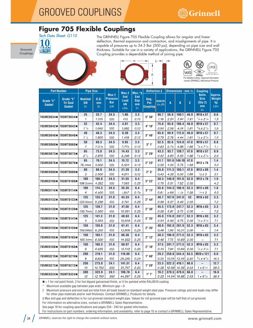
P QRFigure 705 Flexible CouplingsTech Data Sheet: G110 The GRINNELL Figure 705 Flexible Coupling allows for angular and linear
deflection, thermal expansion and contraction, and misalignments of pipe. It is capable of pressures up to 34.5 Bar (500 psi), depending on pipe size and wall thickness. Suitable for use in a variety of applications, the GRINNELL Figure 705 Coupling provides a dependable method of joining pipe.
Part Number Pipe Size
Max.†Pressure
Bar� � � Max.†End LoadkNF G � � Max.*‡
End Gap mmH I � Deflection ‡ Dimensions - mm
H I �Coupling Bolts Size(Qty 2) mmH I � Approx.
WeightkgF G � �Grade “E”
Gasket
Grade “E” Tri-Seal Gasket
Nominal DNH I � O.D.
mmH I � Deg.Per
Coupling
mm/mH I � S T U A B C
705ME0034 705MT003425 33.7 34.5 1.86 3.3
5° 30'96.7 56.9 100.1 46.0 M10 x 57 0.6� � � $ � !
500% � � � � � $ � � � � # � # % $ � + % � � & � ' ( ) # � � � � $
705ME0042 705MT004232 42.4 34.5 4.81 3.3
4° 19'75.0 65.0 106.4 46.0 M10 x 57 0.7� � � � � � � �
500� " � & # � � � $ � � + � # � ! � % � � + � � & � ' ( ) # � � � � !
705ME0048 705MT004840 48.3 34.5 6.30 3.3
3° 46'65.8 69.9 112.8 46.0 M10 x 57 0.7� � * � � + � �
500� " % � & � � � $ � � + # � ! % � % % � � & � ' ( ) # � � � � �
705ME0060 705MT006050 60.3 34.5 9.85 3.3
3° 1'52.5 82.6 124.0 47.8 M10 x 57 0.8# # � $ !
500# " # � ! � � � $ � � � $ $ � # ! % � & & � � & & ' ( ) # � � � �
705ME0073 705MT007365 73.0 34.5 14.43 3.3
2° 29'43.3 93.7 139.7 47.8 M10 x 57 0.9# � * # � & !
500$ " # % � � � � $ � � ! # $ � � + ! � ! � � � & & ' ( ) # � � # � �
705ME0076 705MT007665 76.1 34.5 15.72 3.3
2° 23'41.7 101.6 146.10 47.8
M12 x 761.4 � � � , , $ � � � �
500$ " ! $ % � � � $ � � ! � % � � � ! � ! � � & & $ � �
705ME0089 705MT008980 88.9 34.5 21.39 3.3
2° 3'35.8 111.3 165.1 47.8 M12 x 89 1.4$ $ � ! � �
500% " & � � � � � $ � � % $ % � $ & � � ! � � � & & � * ) $ $ � �
705ME0108 705MT0108100 108.0 34.5 31.55 6.4
3° 22'58.3 140.0 191.0 52.0 M12 x 76 1.9� � & � � , , % � # ! #
500 " � + $ � � # ! � � � ! � ! � � ! # # � � ! % � #
705ME0114 705MT0114100 114.3 34.5 35.35 6.4
3° 11'55.8 144.5 196.9 52.3 M12 x 89 1.8% % � ! � �
500 " + ! # � � # ! � � � ! � � + � ! # � � � � * ) $ % � �
705ME0133 705MT0133125 133.0 31.0 43.33 6.4
2° 44'46.7 167.0 241.0 52 M16 x 83 3.3� $ $ � � , , ! � # $ �
450+ " % � � � # ! � � ! � � � ! + � % + # � � ! - � #
705ME0139 705MT0139125 139.7 31.0 47.56 6.4
2° 36'45.5 173.0 247.7 52.3 M16 x 83 3.3� $ + � , , ! � ! � �
450� � " � + � � � # ! � � ! ! � � & � + � ! # � � � - � #
705ME0141 705MT0141125 141.3 31.0 48.63 6.4
2° 35'45.0 174.8 247.7 52.3 M16 x 83 3.2! ! � ! � $
450� � " + $ & � � # ! � � ! % � � & & + � ! # � � � . ( ) $ � � � �
705ME0159 705MT0159150 159.0 31.0 61.41 6.4
2° 35'40.0 192.0 261.9 52.3 M16 x 83 3.4� ! + � � , , � � # � �
450� $ " & � � � � # ! � � % & � ! � � � � $ � # � � � - � %
705ME0165 705MT0165150 165.1 31.0 66.36 6.4
2° 12'38.3 196.9 271.5 52.3 M16 x 83 3.2� � ! � � , , � � ! � �
450� % " + $ # � � # ! � � % � � ! � � � � + # � � � - � �
705ME0168 705MT0168150 168.3 31.0 68.97 6.4
2° 10'37.5 201.7 271.5 52.3 M16 x 83 3.2� � � � # !
450� ! " ! � # � � # ! � � % ! � + % � � � � + # � � � . ( ) $ � � � �
705ME0219 705MT0219200 219.1 31.0 116.89 6.4
1° 40'29.2 258.8 344.4 63.5 M20 x 121 6.6& & � � # !
450# � " # + # � � # ! � � $ ! � � � � + � $ � ! � # � ! � ' � ) % ' � � % � !
705ME0273 705MT0273250 273.0 24.1 141.31 6.4
1° 20'23.3 322.3 416.1 66.8 – 12.7� � � � � ! � $ ! � $ � " � � � # ! � � # & � # � � + � � � $ & # � � $ � ) � � * # & � �
705ME0324 705MT0324300 323.9 24.1 198.78 6.4
1° 7'19.2 379.5 479.6 66.8 – 16.6� # � # � ! � $ ! � % % " � & � � # ! � � # $ � % � + % � & � & & # � � $ � ) � � * $ � � !
= 1 for red paint finish, 2 for hot dipped galvanised finish, or 5 for painted white RAL9010 coating
* Maximum available gap between pipe ends. Minimum gap = 0.
† Maximum pressure and end load are total from all loads based on standard weight steel pipe. Pressure ratings and end loads may differ for other pipe materials and/or wall thickness. Contact GRINNELL Products for details.
‡ Max end gap and deflection is for cut grooved standard weight pipe. Values for roll grooved pipe will be half that of cut grooved.
For information on alternative sizes, contact a GRINNELL Sales Representative.
See page 19 for coupling specifications and pages 234 - 245 for gasket information.
For instructions on part numbers, ordering information, and availability, refer to page 15 or contact a GRINNELL Sales Representative.
For detailed Listing / Approval information
contact GRINNELL Mechanical Products.
Issue 03, 04, 07
Cert No. 570, 669, 673
Refer to back cover for country-specific contact information
GROOVED COUPLINGS
Grooved
Couplings
25
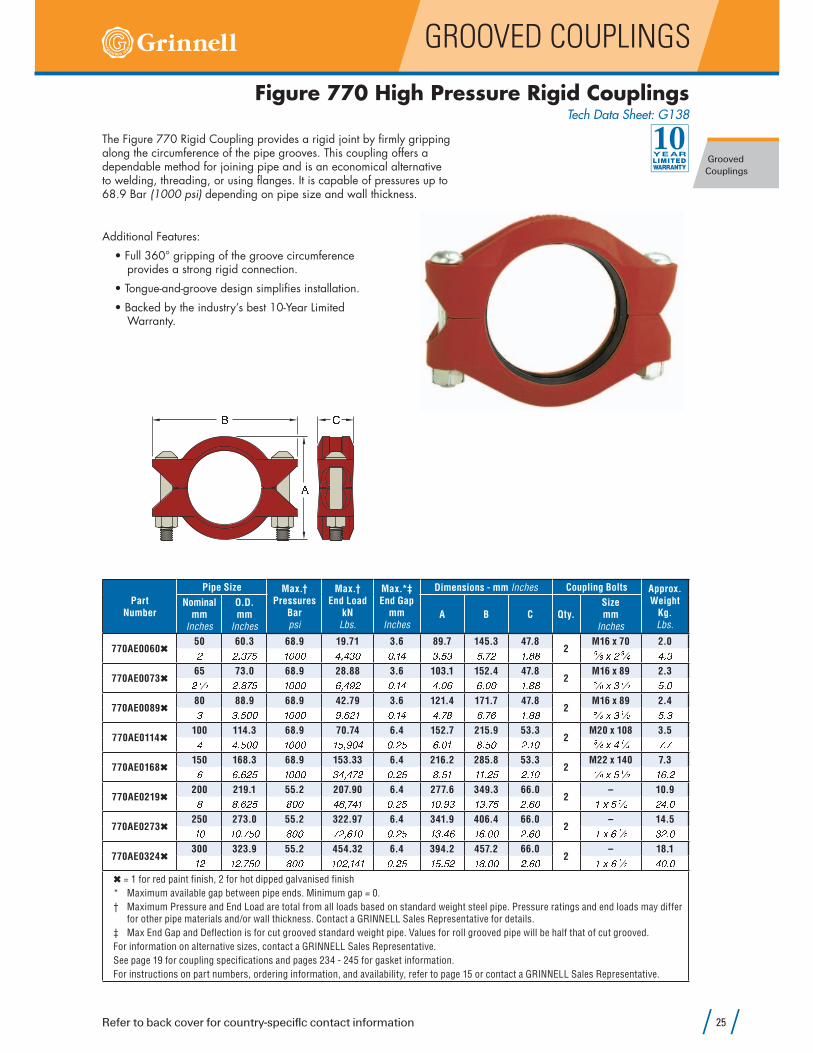
Figure 770 High Pressure Rigid CouplingsTech Data Sheet: G138
The Figure 770 Rigid Coupling provides a rigid joint by firmly gripping along the circumference of the pipe grooves. This coupling offers a dependable method for joining pipe and is an economical alternative to welding, threading, or using flanges. It is capable of pressures up to 68.9 Bar (1000 psi) depending on pipe size and wall thickness.
0/1Additional Features:
provides a strong rigid connection.
Warranty.
Part Number
Pipe Size Max.†Pressures
Barpsi
Max.†End Load
kNLbs.
Max.*‡ End Gap mmInches
Dimensions - mm Inches Coupling Bolts Approx.WeightKg.Lbs.
Nominal mmInches
O.D.mmInches
A B C Qty.SizemmInches
770AE006050 60.3 68.9 19.71 3.6 89.7 145.3 47.8
2M16 x 70 2.0# # � $ ! � � � � % " % $ � � � � % $ � ! $ ! � # � � & & . ( ) # ' � % � $
770AE007365 73.0 68.9 28.88 3.6 103.1 152.4 47.8
2M16 x 89 2.3# � * # � & ! � � � � � " % + # � � � % % � � � � � � � � � & & . ( ) $ � * ! � �
770AE008980 88.9 68.9 42.79 3.6 121.4 171.7 47.8
2M16 x 89 2.4$ $ � ! � � � � � � + " � # � � � � % % � & � � � � � & & . ( ) $ � * ! � $
770AE0114100 114.3 68.9 70.74 6.4 152.7 215.9 53.3
2M20 x 108 3.5% % � ! � � � � � � � ! " + � % � � # ! � � � � & � ! � # � � � ' � ) % � � �
770AE0168150 168.3 68.9 153.33 6.4 216.2 285.8 53.3
2M22 x 140 7.3� � � � # ! � � � � $ % " % # � � # ! & � ! � � � � # ! # � � � V ( ) ! � * � � � #
770AE0219200 219.1 55.2 207.90 6.4 277.6 349.3 66.0
2– 10.9& & � � # ! & � � % � " % � � � # ! � � � + $ � $ � ! # � � � � ) ! � * # % � �
770AE0273250 273.0 55.2 322.97 6.4 341.9 406.4 66.0
2– 14.5� � � � � ! � & � � # " � � � � � # ! � $ � % � � � � � � # � � � � ) � � * $ # � �
770AE0324300 323.9 55.2 454.32 6.4 394.2 457.2 66.0
2– 18.1� # � # � ! � & � � � � # " � % � � � # ! � ! � ! # � & � � � # � � � � ) � � * % � � �
= 1 for red paint finish, 2 for hot dipped galvanised finish
* Maximum available gap between pipe ends. Minimum gap = 0.
† Maximum Pressure and End Load are total from all loads based on standard weight steel pipe. Pressure ratings and end loads may differ for other pipe materials and/or wall thickness. Contact a GRINNELL Sales Representative for details.
‡ Max End Gap and Deflection is for cut grooved standard weight pipe. Values for roll grooved pipe will be half that of cut grooved.
For information on alternative sizes, contact a GRINNELL Sales Representative.
See page 19 for coupling specifications and pages 234 - 245 for gasket information.
For instructions on part numbers, ordering information, and availability, refer to page 15 or contact a GRINNELL Sales Representative.

www.grinnell.com
GROOVED COUPLINGS
Grooved
Couplings
GRINNELL reserves the right to change the contents without notice.26
Figure 707 Heavy Duty Flexible Couplings(Page 1 of 2)
Tech Data Sheet: G130
0/ 101/01 /3 6 4 4 5 2 6 7 4 4 8 9 < = 9 > < ? @ 7 7 4 4 5 @ 6 7 4 4 8 9 A < = 9 B < ? 6 7 7 4 4 5 C 7 7 4 4 8 D E < = D > < ?Part
Number
Pipe SizeMax.†
PressureBar� � � Max.†
End LoadkNLbs.
Max.*‡ End Gap mmInches
Deflection ‡ Dimensions - mm In. Coupling BoltsApprox.WeightKg.Lbs.
Nominal mmInches
O.D.mmInches
DegreesPer
Coupling
mm/mInches/Ft
A B C Qty.SizemmInches
707AE003425 33.7 68.9 6.10 3.3
5° 26'98.4 60.5 101.6 46.0
2M12 x 89 0.9� � � $ � ! � � � � � " $ � � � � � $ � � � % # � $ & % � � � � � & � � * ) $ # � �
707ME004232 42.4 68.9 9.63 3.3
4° 19'75.0 70.0 111.0 46.0
2M12 x 89 1.0� � � � � � � � � � � � # " � � ! � � � $ � � + � # � � % � $ � � & � � * ) $ # � #
707AE004840 48.3 68.9 12.61 3.3
3° 46'65.8 75.4 117.6 46.0
2M12 x 89 1.1� � * � � + � � � � � � # " & $ ! � � � $ � � + # � + % � � $ � � & � � * ) $ # � !
707AE006050 60.3 68.9 19.71 3.3
3° 1'52.5 89.9 133.4 47.8
2M12 x 89 1.4# # � $ ! � � � � % " % $ � � � � $ � � � $ $ � ! % ! � # ! � � & & � * ) $ $ � �
707AE007365 73.0 68.9 28.88 3.3
2° 29'43.3 103.1 146.1 47.8
2M12 x 89 1.6# � * # � & ! � � � � � " % + # � � � $ � � ! # % � � � ! � ! � � & & � * ) $ $ � !
707AE007665 76.1 68.9 31.44 3.3
2° 23'41.7 106.4 146.1 47.8
2M12 x 89 1.8 � " � , , $ � � � � � � � � " � � + � � � $ � � ! � % � � + ! � ! � � & & - % � �
707AE008980 88.9 68.9 42.80 3.3
2° 3'35.8 119.1 162.1 47.8
2M12 x 89 1.8$ $ � ! � � � � � � + " � # � � � � $ � � % $ % � � + � � $ & � � & & � * ) $ % � �
707AE0114100 114.3 68.9 70.75 6.4
3° 11'55.8 151.1 209.6 52.3
2M16 x 83 3.2% % � ! � � � � � � � ! " + � % � � # ! � � � ! � + ! & � # ! # � � � . ( ) $ � � � �
707AE0139125 139.7 68.9 105.6 6.4
2° 30'43.3 178.3 254.0 51.8
2M20 x 121 3.8� $ + " , , ! � ! � � � � � � # $ " ! & � � # ! � � ! # � � # � � � � � # � � % ' � ) % ' � & � $
707AE0141125 141.3 68.9 108.12 6.4
2° 35'45.1 179.8 254.0 52.3
2M20 x 121 4.5! ! � ! � $ � � � � # % " $ � � � � # ! � � ! % � � & � � � � � # � � � ' � ) % ' � � � � �
707AE0165150 165.1 68.9 147.61 6.4
2° 12'38.4 208.0 285.8 52.3
2M20 x 121 5.4� � ! " � , , � � ! � � � � � � $ $ " � & $ � � # ! � � % � & � � + � � � # ! # � � � - � # � �
707AE0168150 168.3 68.9 153.34 6.4
2° 10'37.8 210.8 285.8 52.3
2M20 x 121 5.0� � � � # ! � � � � $ % " % # � � # ! � � % ! & � $ � � � � # ! # � � � ' � ) % ' � � � � �
The GRINNELL Figure 707 Heavy Duty Flexible Coupling allows for angular and linear deflection, thermal expansion and contraction, and misalignments of the pipe. Flexible couplings can act as an “expansion joint”, allowing linear and angular movement of the pipes when properly installed. This coupling is capable of pressures up to 68.9 Bar (1,000 psi), depending on pipe size and wall thickness. Suitable for use in a variety of applications, the Figure 707 Coupling provides a dependable method of joining pipe.
For detailed Listing / Approval information
contact GRINNELL Mechanical Products.
Issue 03, 04, 07
Cert No. 570, 669, 673

Refer to back cover for country-specific contact information
GROOVED COUPLINGS
Grooved
Couplings
27
0/ 101/01 /3 6 4 4 5 2 6 7 4 4 8 9 < = 9 > < ? @ 7 7 4 4 5 @ 6 7 4 4 8 9 A < = 9 B < ? 6 7 7 4 4 5 C 7 7 4 4 8 D E < = D > < ?
Figure 707 Heavy Duty Flexible Couplings(Page 2 of 2)
Tech Data Sheet: G130
Part Number
Pipe SizeMax.†
PressureBar� � � Max.†
End LoadkNLbs.
Max.*‡ End Gap mmInches
Deflection ‡ Dimensions - mm In. Coupling BoltsApprox.WeightKg.Lbs.
Nominal mmInches
O.D.mmInches
DegreesPer
Coupling
mm/mInches/Ft
A B C Qty.SizemmInches
707AE0219200 219.1 55.2 207.91 6.4
1° 40'29.2 271.3 355.6 62.7
2M22 x 165 9.7& & � � # ! & � � % � " % � � � # ! � � $ ! � � � � & � % � � � # � % V ( ) � � * # � � %
707AE0273250 273.0 55.2 322.99 6.4
1° 20'23.3 331.7 417.6 66.8
2– 13.2� � � � � ! � & � � # " � � � � � # ! � � # & � $ � � � � � � % % # � � $ � ) � � * # + � �
707AE0324300 323.9 55.2 454.35 6.4
1° 7'19.2 390.9 478.5 66.8
2– 16.8� # � # � ! � & � � � � # " � % � � � # ! � � # $ � ! � $ + � & � & % # � � $ � ) � � * $ � �
707AE0355350 355.6 20.7 205.43 6.4
1° 2'18.3 423.4 517.7 74.7
2– 20.9� % � % � � � � $ � � % � " � & � � � # ! � � # # � � � � # � � $ & # � + % � ) ! � * % � � �
707AE0406400 406.4 20.7 268.31 6.4
0° 54'15.8 478.3 575.1 74.7
3– 26.8� � � � � � � � $ � � � � " $ � & + � � # ! � � � + � & � & $ # # � � % # � + % � ) ! � * ! + � �
707AE0457450 457.2 20.7 339.58 6.4
0° 48'14.2 541.3 638.0 77.7
3– 35.4� & � & � � � � $ � � � " $ % � � � # ! � � � # � � $ � # ! � � # $ � � � � ) ! � * & � �
707AE0508500 508.0 20.7 419.23 6.4
0° 43'12.5 596.1 708.2 77.7
4– 40.4# � # � � � � � $ � � + % " # % & � � # ! � � � ! # $ � % # � & & $ � � � � � ( ) ! ' � & + � �
707AE0610600 609.6 20.7 603.7 6.4
0° 36'10.8 700.5 812.8 81.0
4– 50.8# % # % � � � � $ � � � $ ! " � � � # ! � � � $ # � ! & $ # � � � $ � � + � � ( ) ! ' � � � # � �
= 1 for red paint finish, 2 for hot dipped galvanised finish
* Maximum available gap between pipe ends. Minimum gap = 0.
† Maximum Pressure and End Load are total from all loads based on standard weight steel pipe. Pressure ratings and end loads may differ for other pipe materials and/or wall thicknesses. Contact a GRINNELL Sales Representative for details.
‡ Max End Gap and Deflection is for cut grooved standard weight pipe. Values for roll grooved pipe will be half that of cut grooved.
For information on alternative sizes, contact a GRINNELL Sales Representative.
For coupling sizes above 300mm (12" ) bolt sizes only available in ANSI.
See page 19 for coupling specifications and pages 234 - 245 for gasket information.
For instructions on part numbers, ordering information, and availability, refer to page 15 or contact a GRINNELL Sales Representative.

www.grinnell.com
GROOVED COUPLINGS
Grooved
Couplings
GRINNELL reserves the right to change the contents without notice.28
Figure 707L Large Diameter CouplingsTech Data Sheet: G133
GRINNELL Figure 707L Large Diameter Coupling is designed for joining large diameter IPS roll grooved pipes. The coupling castings are a two to eight segment design and utilize two bolts at each segment joint to ensure proper connection and seal.
Suitable for use in a variety of applications where there is a need to move large volumes of fluids, the Figure 707L Large Diameter Coupling provides a dependable method of joining pipe.
Pipe Size Max. † Working Pressure
Barpsi
Max. † End Load
kNLbs
Max.* ‡ End Gap mminches
Dimensions BoltsApprox.WeightKg.Lbs.
Nominal mmInches
O.D.mmInches
AmmInches
BmmInches
CmmInches
No Sizein
650 660.4 20.7 708 8.6 754.0 842.0 125.64
V ( ) + W . ( 67.0# � # � � � $ � � � ! + " # + � � $ % # + � � & $ $ � � ! % � + % � % � �700 711.2 12.1 479 8.6 813 920 127
12V ( ) % 82.0# & # & � � � ! � � " ! � � $ % $ # � � $ � � $ ! � � � & � � �
750 762.0 12.1 550 8.6 864 972 12712
V ( ) % 95.0$ � $ � � � � ! � # $ " � � � � $ % $ % � � $ & � $ ! � � # � + � �800 812.8 12.1 626 8.6 914 1022 127
12V ( ) % 94.0$ # $ # � � � ! � % � " % $ � � $ % $ � � � % � � $ ! � � # � � �
900 914.4 12.1 792 8.6 1016 1124 12712
V ( ) % 96.0$ � $ � � � � ! � & " � # & � � $ % % � � � % % � $ ! � � # � # � �1000 1016.0 12.1 978 8.6 1105 1245 140
16� ) $ � * 123.0% � % � � � � ! # � + " + � � � � $ % % $ � ! % + � � ! � ! # � � �
1050 1066.8 12.1 1078 8.6 1156 1295 14016
� ) $ � * 140.0% # % # � � � ! # % # " % ! # � � $ % % ! � ! ! � � ! ! � ! $ � & � �† Maximum pressure and end load are total from all loads based on standard weight steel pipe. Pressure ratings and end loads may differ for
other pipe materials and/or wall thickness. Contact your GRINNELL Representative for details.
* Maximum available gap between pipe ends. Minimum gap = 0.
‡ Max End Gap is for rolled grooved standard weight pipe.
For information on alternative sizes, contact a GRINNELL Sales Representative.
See page 19 for coupling specifications and pages 234 - 245 for gasket information.
For instructions on part numbers, ordering information, and availability, refer to page 15 or contact a GRINNELL Sales Representative.
B
B
B
A
C
C
C
DN700 - DN900 (28" - 36") DN1000 - DN1050 (40" - 42")DN650 (26")
A
A

Refer to back cover for country-specific contact information
GROOVED COUPLINGS
Grooved
Couplings
29
Shurjoint Figure 7707N Large Diameter Flexible Couplings
Shurjoint Tech Data Sheet: C-23The Shurjoint Model 7707N is a two-segment, flexible coupling for use with standard pipe, roll or cut grooved to AWWA C606 specifications.
The Model 7707N Heavy Duty Flexible Coupling is designed for use in a variety of general piping applications of moderate or high pressure services. The Model 7707N couplings feature flexibility that can deal with misalignment, distortion, thermal stress, vibration and noise and also resist seismic tremors. With the use of Model 7707N couplings you can even design a curved layout. See Typical application – Flexible Couplings on Shurjoint Data Sheet #B-19.
The Model 7707N couplings sizes 350 – 600mm (14” – 24”) are com-prised of two identical ductile iron housing segments, an EPDM rubber gasket and one at each segment joint to ensure a positive connection and seal.
Pressure-Temperature Rating
Pipe Size Max. Working PressureAxial
DisplacementmmInches
Angular Movement Dimensions BoltsApprox.WeightKg.Lbs.
NominalmmInches
ActualO.D.mmInches
XS (0.500”)*
Barpsi
STD (0.375”)Barpsi
LW (0.312”)Barpsi
Degree Per
Coupling (°)
Per Pipemm / m in / ft
AmmInches
BmmInches
CmmInches
No.Sizein
350 355.6 20 20 17 6.41° – 02’
9.0 412 479 75 # 15.7� % � % � � � � $ � � $ � � # ! � � � # ! � � � � � � � � # $ � & � & ! # � + ! V ( ) � � * $ % � !400 406.4 20 20 17 6.4
0° – 54’8.0 463 547 75 # 18.4� � � � � � � � $ � � $ � � # ! � � � # ! � � � � � � & � # $ # � � ! $ # � + ! � ) � � * % � � !
450 457.2 20 20 17 6.40° – 48’
7.0 520 605 79 # 22.3� & � & � � � � $ � � $ � � # ! � � � # ! � � � � & # � � % ! # $ � & � $ � � � � ) � � * % � �500 508.0 20 20 17 6.4
0° – 44’6.0 571 656 79 # 24.5# � # � � � � � $ � � $ � � # ! � � � # ! � � � � & # # � % & # ! � & # $ � � � � ) � � * ! % � �
550 558.8 20 20 17 6.40° – 39’
6.0 621.4 724.6 79 # 28.6# # # # � � � � $ � � $ � � # ! � � � # ! � � � � # % � % � # & � ! # $ � � � � ( ) � � * � $ � �600 609.6 20 20 17 6.4
0° – 36’5.0 674 780 79 # 29.5# % # % � � � � $ � � $ � � # ! � � � # ! � � � � � # � � ! ! $ � � � $ � � � � ( ) � � * � ! � �
Deflection or angular movement is the maximum value that a coupling allows under no internal pressure.
* Pressure ratings are based on cut-grooved XS carbon steel pipe.
Refer to the Shurjoint technical data sheet for complete technical information and installation instructions. More information about Shurjoint Piping Products can be found on page 14 in the General Data section of this book or on www.shurjoint.com.
For information on alternative sizes, contact a GRINNELL Sales Representative.
See page 19 for coupling specifications and pages 234 - 245 for gasket information.
For instructions on part numbers, ordering information, and availability, refer to page 15 or contact a GRINNELL Sales Representative.
Nom. Rating
Working Pressure(S40S, Roll-grooved)
Max. ServiceTemperature
Class 150
20.7 Bar @38°C$ � � � � � X � � � Y T EPDM: 110°CZ [ \ ] ^ # $ � Y TNitrile: 82°C_ � U ` � a L ^ � & � Y T
*Working pressure is based on roll- or cut-grooved standard wall carbon steel pipe.
*Proof test pressure: 1.5 times the working pressure, non-shock cold water.
*Burst pressure is engineered minimum 2 times the working pressure.
1 0/
Surface Finish:
for waste water, hydrocarbons, harsh chemicals and sea water services, Drynamels #4900 for exterior (outdoor) architectural applications and others (Option).
For additional details contact Shurjoint.

www.grinnell.com
GROOVED COUPLINGS
Grooved
Couplings
GRINNELL reserves the right to change the contents without notice.30
The GRINNELL Figure 909 Plain End Coupling utilizes hardened gripping teeth to securely grip onto plain and beveled end pipe surfaces. It is capable of pressures up to 51.7 Bar (750 psi) depending on pipe size and wall thickness.
The GRINNELL Figure 909 Plain End Coupling is designed for Schedule 40 steel pipe and is not for use with steel pipe with a Brinnell hardness greater than 150 HB, plastic, cast, or ductile iron pipes. Contact a GRINNELL Sales Representative for recommendations on other materials and pipe schedules.
6 7 4 4 5 b 6 7 4 4 8 D < = A < ? c 3 1 d e f g h 3 7 7 4 4 5 @ 7 7 4 4 8 B < = 9 A < ? c @ 1 d e f g h10 01/ /
Figure 909 Plain End CouplingsTech Data Sheet: G190
Part Number
Pipe Size Max.†Pressures
Barpsi
Max.†End Load
kNLbs.
Dimensions Coupling Bolts Approx.WeightKg.Lbs.
Nominal mmInches
O.D.mmInches
AmmInches
BmmInches
CmmInches
Qty.SizemmInches
909AE006050 60.3 51.7 14.78 93.7 146.1 84.1
2M16 x 90 2.4# # � $ ! ! � $ $ # # � � $ � � + ! � ! $ � $ � . ( ) $ � * ! � %
909AE007365 73.0 41.4 17.33 105.9 158.8 84.1
2M16 x 90 2.7# � * # � & ! � � � $ & + ! � � % � � � � # ! $ � $ � . ( ) $ � * ! � +
909AE007665 76.1 41.4 23.00 111.9 181.1 98.6
2M20 x 121 2.1 � � � , , $ � � � � � � � ! " � � � � % � % � � � $ $ � & & ' � ) % ' � % � �
909AE008980 88.9 41.4 25.68 122.2 192.0 84.1
2M20 x 121 4.1$ $ � ! � � � � � ! # � % � & � � ! � $ � $ � ' � ) % ' � + � �
909AE0114100 114.3 31 31.83 150.6 219.2 98.6
2M20 x 121 6.1% % � ! � � % ! � " � ! � � + ! � + $ & � � $ $ � & & ' � ) % ' � � $ � !
909AE0165150 165.1 20.7 44.30 203.7 293.7 293.6
2– 9.8� � ! � � , , � � ! � � $ � � + " + ! + � � & � � # � � � ! � � � � ! � � ) � � * # � � �
909AE0168150 168.3 20.7 46.00 208.0 296.7 108.0
2– 10.7� � � � # ! $ � � � � " $ % � � ! & � � + � � � � & % � # ! � ) � � * # $ � !
909AE0219200 219.1 17.2 64.97 271.5 346.2 124.7
4M22 x 140 15.9& & � � # ! # ! � � % " � � � � � � � � � + � $ � � $ % � + � V ( ) ! � * $ ! � �
909AE0273250 273.0 17.2 100.93 333.5 403.4 124.7
4M22 x 140 22.0� � � � � ! � # ! � # # " � + � � � � $ � � $ � ! � & & % � + � V ( ) ! � * % & � !
= 1 for red paint finish, 2 for hot dipped galvanised finish
† Maximum Pressure and End Load are total from all loads based on standard weight steel pipe.
Pressure ratings and end loads may differ for other pipe materials and/or wall thickness. Contact a GRINNELL Sales Representative for details.
For information on alternative sizes, contact a GRINNELL Sales Representative.
See page 19 for plain end coupling specifications and pages 234 - 245 for gasket information.
For instructions on part numbers, ordering information, and availability, refer to page 15 or contact a GRINNELL Sales Representative.

Refer to back cover for country-specific contact information
GROOVED COUPLINGS
Grooved
Couplings
31
The GRINNELL Figure 780 Grooved Snap Coupling is designed for quickly connecting and disconnecting cut or rolled grooved piping systems. By utilizing a hinged lever mechanism, grooved piping segments are joined quickly and securely without nuts and bolts. Coupling housing segments are locked in place by securing the lever handle with a split pin. Additional Features:
(5" to 8") feature a cross-ribbed housing design for extra strength.
300 psi).
01 /i j e k f l k m
Figure 780 Grooved Snap CouplingsTech Data Sheet: G145
Part Number
Pipe Size Max. † *WorkingPressure
Barpsi
Max. *End Load
kNLbs.
Max. End Gap mmInches
Dimensions DeflectionApprox.WeightKg.Lbs.
Nominal mmInches
O.D.mmInches
AmmInches
BmmInches
CmmInches
DegreesPer
Coupling
mm/mInches/Ft
780AE004840 48.3 20.7 3.8 1.6 75.0 118.0 47.0
3° 48'66.4 1.0� � * � � + � � $ � � & ! � � � � � # � + ! % � � ! � � & ! � � & � # � #
780AE006050 60.3 20.7 5.9 1.6 86.0 121.0 48.0
3° 31'61.5 1.1# # � $ ! $ � � � " $ # + � � � � $ � $ + % � � � � & + � � % # � %
780AE007365 73.0 20.7 8.7 1.6 92.0 150.0 48.0
2° 30'43.7 1.4# � * # � & ! $ � � � " + % � � � � $ � � # ! � + � � � & + � � ! # $ � �
780AE007665 76.1 20.7 9.4 1.6 92.0 150.0 48.0
2° 24'41.9 1.4 � " � , , $ � � � � $ � � # " � # � � � � � $ � � # ! � + � � � & + � � ! � $ � �
780AE008980 88.9 20.7 12.8 1.6 119.0 163.0 48.0
2° 24'41.9 1.8$ $ � ! � � $ � � # " & & � � � � � % � � + � � % # � � & + � � ! � % � �
780AE0114100 114.3 20.7 21.2 3.2 165.0 205.0 52.0
3° 12'55.9 2.7% % � ! � � $ � � % " � � � � $ � � ! � & � � # � � ! � � � ! � +
780AE0139125 139.7 20.7 31.7 3.2 189.0 253.0 52.0
2° 37'45.7 4.9� $ + " , , ! � ! � � $ � � " � # � � � $ � % % + � + � # � � ! � � ! ! � � � &
780AE0141125 141.3 20.7 32.4 3.2 189.0 253.0 52.0
2° 36'45.4 4.9! ! � ! � ! $ � � " # & + � � � $ � % % + � + � # � � ! � � ! % � � � &
780AE0165150 165.1 20.7 44.3 3.2 213.0 278.0 52.0
2° 14'39.0 5.8� � ! " � , , � � ! � � $ � � + " + ! ! � � � $ & � $ + � � � + % # � � ! � � % � # � &
780AE0168150 168.3 20.7 46.0 3.2 216.0 281.0 52.0
2° 10'37.8 5.8� � � � # ! $ � � � � " $ % � � � � $ & � ! � � � � � � # � � ! � � % ! � # � &
780AE0219200 219.1 20.7 78.0 3.2 278.0 356.0 62.0
1° 40'29.1 9.3& & � � # ! $ � � � " ! # & � � � $ � � � + ! � % � � # # � % % � � $ ! # � � !
= 1 for black paint finish, 2 for hot dipped galvanised finish
† Pressure ratings listed are cold water pressure or maximum working pressure within the service temperature range of the gasket used in the coupling.
* Maximum Working Pressures and End Loads listed are total of internal and external pressures and loads based on Schedule 40 steel pipe grooved in accordance with Standard Cut Groove or Roll Groove Specifications.
For information on alternative sizes, contact a GRINNELL Sales Representative.
See page 19 for coupling specifications and pages 234 - 245 for gasket information.
For instructions on part numbers, ordering information, and availability, refer to page 15 or contact a GRINNELL Sales Representative.
Coatings
(standard)
(optional)
Toggle Links
to ANSI C1010 or C1020
Hinge Pin
conforming to ANSI C1212
Rivet
ANSI C1010
Split Pin
conforming to ASTM A 421
Gasket Specifications
gaskets have a Green colour stripe code for temperature service from -34°C to 110°C ( -30°F to 230°F).
gaskets have an Orange colour stripe code for temperature service from -29°C to 82°C ( -20°F to 180°F).
Refer to data sheet G610 for more gasket information.

www.grinnell.com
GROOVED COUPLINGS
Grooved
Couplings
GRINNELL reserves the right to change the contents without notice.32
Shurjoint Figure XH-70EP Extra Heavy Rigid Couplings
With End Protection (EP) GasketShurjoint Tech Data Sheet: C-09
Pipe Size Max. WorkingPressure
Barpsi
Max. EndLoadkNLbs.
Dimensions Bolt / NutBolt
WeightKg.Lbs.
NominalmmInches
O.D.mmInches
AmmInches
BmmInches
CmmInches
No.Sizein
50 60.3 175 50 90 150 492
. ( ) # ' � 1.5# # � $ ! # ! � � � � � � $ � ! % ! � + � � � + # $ � $65 73.0 175 73.2 103 168 49
2. ( ) # ' � 1.8# � * # � & ! # ! � � � � # # � % � � � � � � � � � + # % � �
80 88.9 175 108.6 122 188 512
. ( ) # ' � 2.2$ $ � ! � � # ! � � # % � % � % � & � � % � # � � � % � &100 114.3 175 179.5 157 222 55
2' � ) % ' � 4.0% % � ! � � # ! � � $ + % � � � � & & � % # � � & � &
150 168.3 140 311.3 218 295 572
V ( ) ! � * 8.0� � � � # ! # � � � � & + � � & � ! & � � � � � # � # ! � � �200 219.1 140 527.6 275 364 70
2� ) ! � * 10.9& & � � # ! # � � � � � � + � � � � & $ � % � $ $ # � ! # % � �
250 273.0 88 514.8 334 424 752
� ) ! � * 14.2� � � � � ! � � # ! � � � $ % � � � $ � � ! � � � � # � + ! $ � � #300 323.9 88 724.7 390 480 75
2 � ) ! � * 16.7� # � # � ! � � # ! � � ! + ! � � � ! � $ ! � & � + $ # � + ! $ � �
* Pressures quoted are based on EP cut grooved XS (Sch. 80) pipe.
CAUTION: Always fasten the bolts to the required torque.
Refer to the Shurjoint technical data sheet for complete technical information and installation instructions. More information about Shurjoint Piping Products can be found on page 14 in the General Data section of this book or on www.shurjoint.com.
For information on alternative sizes, contact a GRINNELL Sales Representative.
See page 19 for coupling specifications and pages 234 - 245 for gasket information.
For instructions on part numbers, ordering information, and availability, refer to page 15 or contact a GRINNELL Sales Representative.
EP Gasket
The Shurjoint Model XH-70EP is designed for use with plastic coated or cement lined pipe. The EP (end protection) gasket serves to form a continuous lined surface at the joint and also helps protect the pipe ends from corrosion. This coupling is rated up to 175 Bar (2500 psi) when used in conjunction with machined EP cut grooves and the applicable pipe.
MATERIAL SPECIFICATIONS
Housing:
ASTM A 395 Gr.65-45-15, min. tensile strength 4481 Bar (65,000 psi).
Surface Finish:
Rubber Gasket: “EP” gasket (Colour code: Orange
stripe) Recommended for petroleum products, air with oil vapors, vegetable and mineral oils within the specified temperature range. Also good for water services under 66°C (150°F). Temperature range: -29°C to 82°C (-20°F to 180°F). Do not use for HOT WATER above 66°C (150°F) or HOT DRY AIR above 60°C (140°F)
Bolts & Nuts:
ASTM A 449-83a (or A 183 Gr. 2), minimum tensile strength 7584 Bar (110,000 psi), Zinc electroplated, with heavy-duty hexagonal nuts to ASTM A 563
10 /

Refer to back cover for country-specific contact information
GROOVED COUPLINGS
Grooved
Couplings
33
Figure 716 Flexible Reducing CouplingsTech Data Sheet: G120
The GRINNELL Figure 716 Flexible Reducing Coupling allows for a direct transition between two different pipe sizes and replaces two couplings and a reducing fitting. It is capable of pressures up to 34.5 Bar (500 psi) depending on pipe size and wall thickness. A flexible reducing coupling is not recommended for low-temperature applications. 1 /0
Part Number
Pipe Size Max.†Pressures
Bar� � � Max.†End LoadkNF G � � Max.*‡
End GapmmH I � Deflection ‡
Dimensions mm
H I � Coupling Bolts Size(Qty 2) mmH I � Approx.
WeightkgF G � �Nominal
DNH I � O.D.mmH I � Degrees
Per Coupling
mm/mH I � S T U A B C
716AE201550 x 40 60.3 x 48.3 34.5 6.31 3.3
1° 53'32.9 88.9 128.5 47.8 M10 x 57 1.3# ) � W � * # � $ ! ) � � + � � ! � � � % � & � � � $ � � $ + $ � ! � ! � � � � � & & ' ( ) # W � � # � &
716AE252065 x 50 73.0 x 60.3 34.5 9.85 3.3
1° 33'27.1 101.6 139.7 47.8 M120 x 57 1.5# W � * ) # # � & ! ) # � $ ! ! � � # # � ! � � � $ � � $ # % � � � ! � ! � � � & & ' ( ) # W � � $ � $
716ME262065 x 50 76.1 x 60.3 34.5 9.85 3.3
1° 34'27.3 106.4 149.4 47.8 M12 x 89 1.5 � � � , , ) # $ � � � � ) # � $ ! ! � � # # � ! � � � $ � � $ $ % � � + ! � & & � � & & $ � $
716AE302080 x 50 88.9 x 60.3 34.5 9.85 3.3
1° 17'22.4 119.1 165.1 47.8 M12 x 89 2.0$ ) # $ � ! � � ) # � $ ! ! � � # # � ! � � � $ � � # % � � + � � ! � � � & & � * ) $ % � $
716AE302580 x 65 88.9 x 73.0 34.5 14.44 3.3
1° 17'22.4 119.1 165.1 47.8 M12 x 89 1.8$ ) # W � * $ � ! � � ) # � & ! ! � � $ # % � � � � $ � � # % � � + � � ! � � � & & � * ) $ $ � +
716ME302680 x 65 88.9 x 76.1 34.5 15.72 3.3
1° 17'22.4 119.1 165.1 47.8 M12 x 89 1.9$ ) � � � , , $ � ! � � ) $ � � � � ! � � $ ! $ % � � � $ � � # % � � + � � ! � � � & & % � #
716AE4220100 x 60 114.3 x 60.3 34.5 9.85 4.8
2° 38'46.0 152.4 206.5 50.8 M16 x 83 2.4% ) # % � ! � � ) # � $ ! ! � � # # � ! � � � + � � ! ! � � � � & � � $ # � � � . ( ) $ W � � ! � #
716AE4225100 x 65 114.3 x 73.0 34.5 14.44 4.8
2° 38'46.0 152.4 206.5 50.8 M16 x 83 3.0% ) # W � * % � ! � � ) # � & ! ! � � $ # % � � � � + � � ! ! � � � � & � � $ # � � � . ( ) $ W � � � �
716ME4226100 x 65 114.3 x 76.1 34.5 15.72 4.8
2° 38'46.0 152.4 206.5 50.8 M16 x 83 2.8% ) � � � , , % � ! � � ) $ � � � � ! � � $ ! $ % � � � + � � ! ! � � � � & � � $ # � � � � � #
716AE4230100 x 80 114.3 x 88.9 34.5 21.40 4.8
2° 38'46.0 152.4 206.5 50.8 M16 x 83 2.8% ) $ % � ! � � ) $ � ! � � ! � � % & � � � � � + � � ! ! � � � � & � � $ # � � � . ( ) $ W � � � � #
716ME5242125 x 100 139.7 x 114.3 34.5 35.37 6.4
2° 38'46.0 179.3 241.3 52.3 M20 x 121 4.4� $ + � , , ) % ! � ! � � ) % � ! � � ! � � + ! # � � # ! � � ! ! � � � + � ! � # � � � + � �
716AE5342125 x 100 141.3 x 114.3 34.5 35.37 6.4
2° 5'36.4 181.1 242.8 52.3 M20 x 121 4.4! ) % ! � ! � $ ) % � ! � � ! � � + ! # � � # ! � � % % � � $ + � ! � # � � � ' � ) % W ' � + � �
716ME6242150 x 100 165.1 x 114.3 27.6 28.30 6.4
1° 50'32.0 207.8 274.6 52.3 M20 x 121 5.8� � ! � � , , ) % � � ! � � ) % � ! � � % � � � $ � # � � # ! � � $ & & � � & � � � & � # � � � � # � &
716AE6342150 x 100 168.3 x 114.3 27.6 28.30 6.4
1° 44'30.0 212.9 276.4 52.3 M20 x 121 5.8� ) % � � � # ! ) % � ! � � % � � � $ � # � � # ! � � $ � & � $ & � � � & & # � � � ' � ) % W ' � � # � &
716AE6353150 x 125 168.3 x 141.3 27.6 43.25 6.4
1° 44'30.0 212.9 276.4 52.3 M20 x 121 6.3� ) ! � � � # ! ) ! � ! � $ % � � + # # � � # ! � � $ � & � $ & � � � & & # � � � ' � ) % W ' � � $ � &
716AE8063200 x 150 219.1 x 168.3 27.6 61.33 6.4
1° 15'21.0 271.5 349.3 57.2 M22 x 165 9.1& ) � & � � # ! ) � � � # ! % � � � $ & + � � # ! � � # � � � � � + � $ � ! # � # ! V ( ) � W � * # � � �
= 1 for red paint finish, 2 for hot dipped galvanised finish
* Maximum available gap between pipe ends. Minimum gap = 0.
† Maximum pressure and end load are total from all loads based on standard weight steel pipe. Pressure ratings and end loads may differ on other pipe materials and/or wall thickness. Contact GRINNELL Products for details.
‡ Max end gap and deflection is for cut grooved standard weight pipe. Values for roll grooved pipe will be half that of cut grooved.
For information on alternative sizes, contact a GRINNELL Sales Representative.
See page 19 for coupling specifications and pages 234 - 245 for gasket information.
For instructions on part numbers, ordering information, and availability, refer to page 15 or contact a GRINNELL Sales Representative.
For detailed Listing / Approval information
contact GRINNELL Mechanical Products.
Issue 03, 04, 07
Cert No. 570, 669, 673

www.grinnell.com
GROOVED COUPLINGS
Grooved
Couplings
GRINNELL reserves the right to change the contents without notice.34
Figure 702 Mechanical Outlet Couplings(Page 1 of 2)
Tech Data Sheet: G220 The GRINNELL Figure 702 Mechanical Outlet Coupling has the combined features of a coupling and a reducing outlet, eliminating the need for a mechanical tee or other associated couplings. The coupling is available in grooved, male-threaded, or female-threaded outlets. This design makes installation faster, safer, and more cost effective on the job site.
Additional features:(1 1 ⁄ 2" to 6")
(500 psi)
(10" HG)
Figure 702 Outlet Coupling with Female BSP Outlet
Figure 702 Outlet Coupling with Male BSP Outlet
Figure 702 Outlet Coupling with Grooved Outlet
01 // 0101 nRun Pipe Size Branch Size
End GapRange mmH I � Max.
Run End LoadkNF G � � Dimensions
mm H I �
Bolt Size H I � Approx.
Weight kgF G � �Nominal
DNH I � O.D.mmH I � Female n
ThreadmmH I � Male n
ThreadmmH I � Grooved
A B C TNominal mmH I � O.D.
mmH I �40� W � * 48.3� � + � � 21.3 – – – 20-22
6.3� % � & – 114.3 70.0 52.0 ' ( ) # W � ( 1.2� * - - - � � & � W � � & & - % � ! � # � ! # � � � # � �26.9 – – – 20-22 – 114.3 70.0 52.0 1.2' � - - - � � & � W � � & & - % � ! � # � ! # � � � # � �33.7 – – – 20-22 – 114.3 70.0 49.0 1.3� - - - � � & � W � � & & - % � ! � # � ! � � + % # � +
50# 60.3# � $ ! 21.3 – – – 20-22
9.9# # � ! – 127.0 70.0 59.0 ' ( ) # W � ( 1.4� * - - - � � & � W � � & & - ! � � � # � ! # � $ # $ � �26.9 – – – 20-22 – 127.0 70.0 59.0 1.4' � - - - � � & � W � � & & - ! � � � # � ! # � $ # $ � �33.7 33.7 25 33.7 20-22 89.0 127.0 70.0 56.0 1.5� � � � � $ � ! � � & � W � � & & $ � ! � ! � � � # � ! # � # � $ � $
65# W � * 73.0# � & ! 21.3 – – – 32-38
14.4$ # % � – 161.0 83.0 56.0 � * ) # W ' ( 2.2� * - - - � � # ! W � � ! � - � � $ $ $ � # ! # � # � % � &26.9 – – – 32-38 – 161.0 83.0 65.0 2.1' � - - - � � # ! W � � ! � - � � $ $ $ � # ! # � ! � % � �33.7 – – – 32-38 – 161.0 83.0 62.0 4.4� - - - � � # ! W � � ! � - � � $ $ $ � # ! # � % % # � #42.4 42.4 32 42.4 32-38 94.0 161.0 83.0 – 2.3� W � � � W � � � W � � � � � � � � � # ! W � � ! � $ � � � � $ $ $ � # ! - ! � �48.3 48.3 40 48.3 32-38 94.0 161.0 83.0 – 5.9� W � * � W � * � W � * � � + � � � � # ! W � � ! � $ � � � � $ $ $ � # ! - # � %

Refer to back cover for country-specific contact information
GROOVED COUPLINGS
Grooved
Couplings
35
Figure 702 Outlet Coupling with Female BSP Outlet
Figure 702 Outlet Coupling with Male BSP Outlet
Figure 702 Outlet Coupling with Grooved Outlet
01 // 0101 n
Figure 702 Mechanical Outlet Couplings(Page 2 of 2)
Tech Data Sheet: G220
Run Pipe Size Branch SizeEnd GapRange mmH I � Max.
Run End LoadkNF G � � Dimensions
mm H I �
Bolt Size H I � Approx.
Weight kgF G � �Nominal
DNH I � O.D.mmH I � Female n
ThreadmmH I � Male n
ThreadmmH I � Grooved
A B C TNominal mmH I � O.D.
mmH I �80$ 88.9$ � ! � � 26.9 – – – 32-38
21.4% & � � – 175.0 83.0 72.0 � * ) $ 2.7' � - - - � � # ! W � � ! � - � � & $ � # ! # � & $ ! � +33.7 33.7 25 33.7 32-38 102.0 175.0 83.0 70.0 2.8� � � � � $ � ! � � # ! W � � ! � % � � � � � & $ � # ! # � ! � � #42.4 – – – ♦ ♦ ♦ ♦ ♦ ♦� W � � - - -
♦ ♦ ♦ ♦ ♦ ♦
48.3 48.3 40 48.3 32-38 102.0 175.0 83.0 – 2.9� W � * � W � * � W � * � � + � � � � # ! W � � ! � % � � � � � & $ � # ! - � � %100% 114.3% � ! � � 26.9 – ♦ ♦ 41-46
35.4 + ! # ♦ 211.0 93.0 94.0 . ( ) $ W � * 4.2' � -♦ ♦
� � � $ W � � & �♦
& � $ � $ � � � $ � � + � #33.7 – ♦ ♦ 41-46 ♦ 211.0 93.0 91.0 4.3� -
♦ ♦
� � � $ W � � & �♦
& � $ � $ � � � $ � ! & + � !48.3 48.3 40 48.3 41-46 124.0 211.0 93.0 84.0 4.3� W � * � W � * � W � * � � + � � � � � $ W � � & � % � & & & � $ � $ � � � $ � $ � + � !60.3 60.3 50 60.3 41-46 124.0 211.0 93.0 – 4.5# # # # � $ ! � � � $ W � � & � % � & & & � $ � $ � � � - + � +
150� 168.36.625
33.7 – 25 33.7 41-46
76.7� " # $ ! – 276.0 94.0 121.0 . ( ) $ W � * 6.0� - � � � $ � ! � � � $ W � � & � - � � � & � $ � � % � � � $ � #– – 32 42.4 ♦ ♦ ♦ ♦ ♦ ♦- - � W � � � � � � �
♦ ♦ ♦ ♦ ♦ ♦
48.3 48.3 40 48.3 41-46 154.0 276.0 94.0 121.0 6.2� W � * � W � * � W � * � � + � � � � � $ W � � & � � � � � � � � & � $ � � % � � � $ � �60.3 60.3 50 60.3 41-46 154.0 276.0 94.0 – 6.5# # # # � $ ! � � � $ W � � & � � � � � � � � & � $ � � - � % � $
n Threads are BSP. Some size outlets are available with NPT threads. Contact GRINNELL Products for details.
♦ Contact GRINNELL Sales Representative for dimension details.
For information on alternative sizes, contact a GRINNELL Sales Representative.
See page 19 for coupling specifications and pages 234 - 245 for gasket information.
For instructions on part numbers, ordering information, and availability, refer to page 15 or contact a GRINNELL Sales Representative.

www.grinnell.com
GROOVED COUPLINGS
Grooved
Couplings
GRINNELL reserves the right to change the contents without notice.36
Shurjoint Figure 7706-T Transition Couplings Shurjoint Tech Data Sheet: C-07
Model 7706-T Transition Couplings allows for a direct transition from IPS pipe sizes to ISO pipe sizes.
Pipe Size Max. EndLoadkNLbs.
Axial Displacement
mmInches
Angular Movement Dimensions - mm InchesBolt / Nut Sizein
Approx.WeightKg.Lbs.
NominalmmInches
O.D.mmInches
Per CouplingDegree
Per Pipemm/min/ft.
A B C
65 x 65 73.0 x 76.1 5.90 0 ~ 3.2 # Y W # % o 21.0 102 138 48 M10 x 55 1.2# � * ) � � � , , # � & ! ) $ � � � � � $ $ � W p � � � $ � � # ! % � � # ! � % $ � � & + ' ( ) # � ( # � �150 x 150 168.3 x 165.1 44.29 0 ~ 6.4 � Y W � � o 19.0 200 270 53 M16 x 90 3.5� ) � � ! � � , , � � � # ! ) � � ! � � + + � � � p � � # ! � � # $ � & � � � � $ # � � + . ( ) $ � * �
*Deflection or angular movement is the maximum value that a coupling allows with no internal pressure.
Refer to the Shurjoint technical data sheet for complete technical information and installation instructions. More information about Shurjoint Piping Products can be found on page 14 in the General Data section of this book or on www.shurjoint.com.
For information on alternative sizes, contact a GRINNELL Sales Representative.
See page 19 for coupling specifications and pages 234 - 245 for gasket information.
For instructions on part numbers, ordering information, and availability, refer to page 15 or contact a GRINNELL Sales Representative.
Pressure-Temperature Rating
Nom. Rating
Working Pressure(S40S, Roll-grooved)
Max. ServiceTemperature
Class 15020.7 Bar @ 38°C$ � � � � � X � � � Y T EPDM: 110°CZ [ \ ] ^ # $ � Y T
Nitrile: 82°C_ � U ` � a L ^ � & � Y T*Working pressure is based on roll- or cut-grooved standard wall
carbon steel pipe.
*Proof test pressure: 1.5 times the working pressure, non-shock cold water.
*Burst pressure is engineered minimum 2 times the working pressure.
MATERIAL SPECIFICATIONSHousing:
ASTM A 395, Gr. 65-45-15, min. tensile strength 4481 Bar (65,000 psi).
Surface Finish:
red.
(Option)
Rubber Gasket:
(Colour code: Green stripe) Good for cold & hot water up to 110°C (230°F). Also good for services for water with acid, water with chlorine, deionized water, seawater and waste water, dilute acids, oil-free air and many chemicals. Not recommended for petroleum oils, minerals oils, solvents and aromatic hydrocarbons. Maximum Temperature Range: -34°C to 110°C (-30°F to 230°F)*. * EPDM gaskets for water services are not recommended for steam services unless couplings or components are accessible for frequent gasket replacement.
(Colour code: Orange stripe) Recommended for petroleum products, air with oil vapors, vegetable and mineral oils within the specified temperature range. Also good for water services under 66°C (150°F). Temperature range: -29°C to 82°C (-20°F to 180°F). Do not use for HOT WATER above 66°C (150°F) or HOT DRY AIR above 60°C (140°F)
Grade “L” - Silicone.
For additional details contact Shurjoint.
Bolts & Nuts:
ASTM A 449-83a (or A 183 Gr. 2), minimum tensile strength 7584 Bar (110,000 psi), Zinc electroplated, with heavy-duty hexagonal nuts to ASTM A 563.
1 0/q r sr q r tq s ur q r t

Refer to back cover for country-specific contact information
GROOVED COUPLINGS
Grooved
Couplings
37
Electrical Continuity
Test pipe at TÜV Rheinland®
Couplings in Galvanised FinishMost GRINNELL Grooved Couplings in galvanised finish comply to the electric conductivity according to clause 11.1.2 of EN 61537-2007. Tests were performed by TÜV Rheinland® and test reports are available upon request.
Part Number
Suitable for size Coupling
Inches
ApproxWeightkg
CLIP0103� W $ � � � � !
CLIP0406% W � � � � � !
CLIP0812& W � # � � � � !
For instructions on part numbers, ordering information, and availability, refer to page 15 or contact a GRINNELL Sales Representative.
Couplings in Painted FinishEarth bonding of the GRINNELL couplings in painted finish can be made in steel pipework systems with an electrical continuity clip. This clip, manufactured from 301-grade stainless steel, is designed to ensure electrical continuity in situations of high current loading and/or corrosive environments, providing equipotential bonding of the conductive parts. It is recommended that the pipework is assembled and installed as recommended and that
the pipework is bonded to the electrical earth and tested in accordance with the I.E.E. regulations for bonding (earthing). Installation should be regularly checked for equipotential bonding (earthing) in case of accidental damage or unauthorised pipework modifications. Following any future modification, electrical continuity clips must be used and the installation re-tested for equipotential bonding.
v w n / x y / v w n / x y /

www.grinnell.com
GROOVED COUPLINGS
Grooved
Couplings
GRINNELL reserves the right to change the contents without notice.38
These installation instructions do not take the place of nor do they eliminate the need for the installer to fully read and understand the complete GRINNELL Products Installation Handbook (refer to IH-1000M). Always review the GRINNELL Products Installation Handbook and individual product tech data sheets for the latest instructions, techniques, and care and maintenance information. This document does not supersede or replace the GRINNELL Products Installation Handbook or individual product tech data sheets. Current documentation can be obtained by contacting your GRINNELL sales Representative or visiting www.grinnell.com.
GRINNELL Coupling Installation InformationInstallation Handbook: IH-1000M
WARNING
Failure to follow these instructions may result in improper product installation, joint failure or leakage, serious per-sonal injury, and/or property damage.
The following instructions should be used as a guideline for the proper installation of GRINNELL Grooved Products.
1. Always read and understand the instructions.
2. To avoid serious personal injury always wear appro-priate personal protective equipment (ppe), such as safety glasses, hard hat and foot protection.
3. Never remove any piping component without verifying that the system is de-pressurized and drained. Failure to due so may result in serious personal injury.
4. Ensure that the supplied gasket is suitable for the in-tended application. To prevent deterioration of the gasket material, a petroleum lubricant should never be used. Use a recommended lubricant to install the gasket.
5. The pipe groove dimensions must be in accordance with Standard Roll Groove or Cut Groove Specifica-tions. Refer to Pages 221 to 232 or Tech Data Sheet G710 for additional information.
*Note: The samples that were tested contained the GRINNELL Figure 707 high pressure flexible couplings, and the GRINNELL Figure 260 end caps of the appropriate size. These were used on the assembly to test system components as related in a field environment. The rated or working pressure of these items is 68.9 bar (1,000 psi)
*Note: The material of both the fittings and couplings used in this testing is found on page nine of the GRINNELL Handbook. This material is Ductile Iron Casting Grade 65-45-12, which has an elongation in 51mm (2”) of 12%.
The Component Proof Test in ASME A17.1 – 2004, section 3.19.1.3 requires testing to section 8.2.8.5, or five times the rated pressure.
The calculation of the factor of safety located in section 8.2.8.5 would then be calculated as F = (5.04 / 12 – 2.8) + 2.7. This then, according to section 8.2.8.5, would be a requirement safety factor of 3.25. The minimum pressure requirement of these components then would be 224.1 bar (3,250 psig)
ASME Standard Note
6. Ensure that the coupling keys are engaged in the grooves.
7. Always tighten nuts evenly by alternating sides. Un-even tightening can cause the gasket to pinch or bind. If a gasket becomes pinched, replace it immediately.
8. Torque values are supplied as a guideline and may be used when setting the torque on power impact wrench-es. Always refer to the power impact wrench manufac-turer’s instructions for settings.
9. Exceeding the suggested torque values may cause damage to the coupling and/or result in pipe-joint fail-ure. Minimum bolt torque is required for coupling to meet the published performance parameters.
10. Always inspect each joint to ensure that the coupling is properly installed.
EPDM, Tri-Seal gaskets are recommended for freezer applications. Reducing Couplings are not recommended for freezer applications. For dry pipe and freezer applications, use the Tri-Seal freezer gasket with a petroleum-free silicone lubricant. Standard lube is not recommended for this application as it freezes and can cause leakage.