Mechanical braking systems for trains
43
THESIS FOR THE DEGREE OF DOCTOR OF PHILOSOPHY IN SOLID AND STRUCTURAL MECHANICS Mechanical braking systems for trains A study of temperatures, fatigue and wear by experiments and simulations MANDEEP SINGH WALIA Department of Mechanics and Maritime Sciences CHALMERS UNIVERSITY OF TECHNOLOGY Gothenburg, Sweden, 2019
Transcript of Mechanical braking systems for trains

THESIS FOR THE DEGREE OF DOCTOR OF PHILOSOPHY IN SOLID AND STRUCTURAL MECHANICS
Mechanical braking systems for trains A study of temperatures, fatigue and wear by
experiments and simulations
M A N D E E P S I N G H W A L I A
Department of Mechanics and Maritime Sciences CHALMERS UNIVERSITY OF TECHNOLOGY
Gothenburg, Sweden, 2019

Mechanical braking systems for trains A study of temperatures, fatigue and wear by experiments and simulations M A N D E E P S I N G H W A L I A ISBN 978-91-7905-195-2
Ⓒ MANDEEP SINGH WALIA, 2019
Doktorsavhandlingar vid Chalmers tekniska högskola Ny serie nr. 4662 ISSN: 0346-718X Department of Mechanics and Maritime Sciences Chalmers University of Technology SE-412 96 Gothenburg Sweden Telephone +46 (0)31 7721000
Cover: Tread temperatures measured by a thermocamera (top left) at RTRI, Japan. Experimental setup for temperature measurement (bottom left) on a postal wagon. Simulated temperatures for wheel tread (top right) and brake disc (bottom right).
Chalmers Reproservice
Gothenburg, Sweden 2019

i
Mechanical braking systems for trains A study of temperatures, fatigue and wear by experiments and simulations MANDEEP SINGH WALIA Department of Mechanics and Maritime Sciences Chalmers University of Technology
ABSTRACT
Increased demand for shorter travel times, higher axle loads, increased volumes and increased punctuality of railway traffic calls for a better design and management of the railway subsystems. The present thesis deals with aspects of mechanical friction brakes, in the form of tread brakes and disc brakes. These are critical for reliable, safe and economical operation of trains. The thesis establishes models and simulation tools for frictional braking systems that may operate in parallel with an electrodynamic braking system.
A main focus is the influence of thermal loading on rolling contact fatigue from tread brakes at stop braking. A simulation methodology for thermomechanical cracking of railway wheel treads due to rolling contact and repeated stop braking by tread brakes, is established based on full-scale brake rig experiments. Building on the same approach, plastic deformation of the tread is also investigated. The results indicate that tread damage increases drastically for frictional temperatures above some 450 ºC.
Another focus is temperatures and wear of tread brakes and disc brakes under operational loading. In two field test campaigns, detailed instrumentation and continuous measurements of relevant temperatures and braking parameters are combined with intermittent measurement of wear of friction brake components. Wear of brake blocks and wheel treads is quantified. It is found that the tread wear introduced by the block contact dominates for trailing wheelsets, whereas for powered wheelsets wear from tractive forces in the wheel–rail contact can be of equal importance. In a study on disc brakes, temperatures and wear performance are compared for two friction pairs: one new segmented disc with sintered pads and a traditional disc with an undivided friction ring combined with organic pads. It is found that the discs have similar braking temperatures, but that the wear of disc and pads is substantially lower for the segmented disc. A numerical investigation of thermomechanical fatigue damage of the two disc types indicates that the segmented disc also has a substantially longer fatigue life. Keywords: Railway braking, tread brakes, disc brakes, temperatures, fatigue, wear, experiments, simulations

ii

iii
To my parents
Amarjit Singh Walia
and
Satinder Kaur Walia

iv

v
PREFACE
The work presented in this thesis was carried out at the Division of Dynamics in the Department of Mechanics and Maritime Sciences at Chalmers University of Technology between September 2014 and October 2019. It was conducted as part of the activities within the National Centre of Excellence in Railway Mechanics CHARMEC (CHAlmers Railway MEChanics, www.charmec.chalmers.se), under the project name SD10 – “Enhanced mechanical braking systems for modern trains”. The project has been supported by CHARMEC's industrial partners. Especially the support from Bombardier Transportation, Faiveley Transport, Green Cargo and SNC-Lavalin is gratefully acknowledged.
ACKNOWLEDGEMENTS
Firstly, I would like to express my deepest gratitude to my main supervisor Docent Tore Vernersson and my co-supervisor Professor Roger Lundén for their invaluable guidance, continuous support, encouragement, commitment and generously sharing their knowledge during these years. The work in this thesis would not have been possible to accomplish without your contributions. Also, I am thankful to my examiner Professor Anders Ekberg for his valuable inputs and efforts during this time.
Also, special thanks go to the co-authors of the appended papers Dr Ali Esmaeili, Professor Magnus Ekh, Professor Johan Ahlström, Dr Kazuyuki Handa, Dr Katsuyoshi Ikeuchi, Mr Fredrik Blennow, Mr Markus Meinel, Dr Gaël Le Gigan and Mr Bjarke Raaby for the knowledge exchange and cooperation we had in preparing the papers. I also acknowledge Professor Emeritus Bengt Åkesson who assisted in improving my manuscripts.
Furthermore, I really appreciate the assistance I received from Mr Jan Möller, Mr Håkan Brandt, Mr Olof Thunberg, Mr Kent Staaf, Mr Kristoffer Mossheden and Mr Daniel Blomstrand during field experiments. Also, discussions in the project reference group with Mr Roger Deuce, Mr Anders Lönnermo and Mr Manohar Singh, including co-authors Blennow and Meinel, were very fruitful.
I would like to take the opportunity to thank all my friends and colleagues at the Division of Dynamics and the Division of Material & Computational Mechanics, for interesting discussions about everything and for their maintaining a nice and joyful working environment.
Finally, I would like to express my love and gratitude to my family for their endless support during all these years. Last but not least, I am thankful to my better half Maryam Akbari for her love, patience and understanding during this time.
Gothenburg, October 2019
Mandeep Singh Walia

vi
vii
THESIS
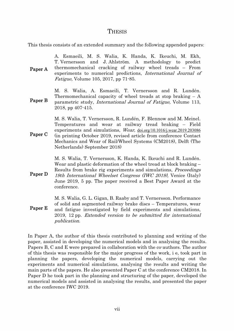
This thesis consists of an extended summary and the following appended papers:
Paper A
A. Esmaeili, M. S. Walia, K. Handa, K. Ikeuchi, M. Ekh, T. Vernersson and J. Ahlström. A methodology to predict thermomechanical cracking of railway wheel treads – From experiments to numerical predictions, International Journal of Fatigue, Volume 105, 2017, pp 71-85.
Paper B
M. S. Walia, A. Esmaeili, T. Vernersson and R. Lundén. Thermomechanical capacity of wheel treads at stop braking – A parametric study, International Journal of Fatigue, Volume 113, 2018, pp 407-415.
Paper C
M. S. Walia, T. Vernersson, R. Lundén, F. Blennow and M. Meinel. Temperatures and wear at railway tread braking – Field experiments and simulations, Wear, doi.org/10.1016/j.wear.2019.203086 (in printing October 2019, revised article from conference Contact Mechanics and Wear of Rail/Wheel Systems (CM2018), Delft (The Netherlands) September 2018)
Paper D
M. S. Walia, T. Vernersson, K. Handa, K. Ikeuchi and R. Lundén. Wear and plastic deformation of the wheel tread at block braking – Results from brake rig experiments and simulations, Proceedings 19th International Wheelset Congress (IWC 2019), Venice (Italy) June 2019, 5 pp. The paper received a Best Paper Award at the conference.
Paper E
M. S. Walia, G. L. Gigan, B. Raaby and T. Vernersson. Performance of solid and segmented railway brake discs – Temperatures, wear and fatigue investigated by field experiments and simulations, 2019, 12 pp. Extended version to be submitted for international publication.
In Paper A, the author of this thesis contributed to planning and writing of the paper, assisted in developing the numerical models and in analysing the results. Papers B, C and E were prepared in collaboration with the co-authors. The author of this thesis was responsible for the major progress of the work, i e, took part in planning the papers, developing the numerical models, carrying out the experiments and numerical simulations, analysing the results and writing the main parts of the papers. He also presented Paper C at the conference CM2018. In Paper D he took part in the planning and structuring of the paper, developed the numerical models and assisted in analysing the results, and presented the paper at the conference IWC 2019.

viii

ix
CONTENTS
Abstract i
Preface v
Acknowledgements v
Thesis vii
Contents ix
I Extended Summary 1
1 Introduction 3
1.1 Background and motivation ......................................................................... 3
2 Mechanical braking systems for trains 7
2.1 Tread brake ................................................................................................... 8
2.2 Disc brake ...................................................................................................... 8
3 Phenomena – experiments and analyses 9
3.1 Braking temperatures ................................................................................... 9
3.2 Thermomechanical fatigue ......................................................................... 13
3.3 Wear ............................................................................................................. 16
4 Summary of appended papers 20
4.1 Paper A ........................................................................................................ 20
4.2 Paper B ........................................................................................................ 20
4.3 Paper C ........................................................................................................ 21
4.4 Paper D ........................................................................................................ 22
4.5 Paper E ........................................................................................................ 22
5 Concluding remarks 24
6 Future developments 28
References 29
II Appended Papers A – E 33

x

1
Part I
Extended Summary

2

3
1 Introduction
1.1 Background and motivation
In past decades, environmental awareness and new regulations combined with demands on cost reductions and improved operational performance have led to accelerated new developments in railway operations. Together with the stride towards shorter travel times, higher axle loads and increased traffic volumes with improved safety, this imposes great challenges on the railway industry. In this context, it is highly important to understand the factors that limit the capacity of various systems and components that are in use. In particular, it is essential to be able to predict damage to avoid removal of trains from revenue traffic, operational failures or even derailments. In addition to safety, these issues are major cost drivers and disrupt operations.
Braking systems are critical for reliable and safe operation of trains. Modern trains are often equipped with a computer-controlled braking system that can flexibly distribute braking power between different braking subsystems. These subsystems can consist of electrodynamic (ED) brakes that act in combination with mechanical brakes in the form of tread brakes and/or disc brakes. Ideally, ED brakes are utilized which allows regenerated energy to be fed back to the main power supply. However, as the efficiency of the ED brake is speed-dependent, additional braking must be performed using mechanical brakes. Hence the use of the mechanical brakes has lately changed substantially, from a situation where it takes all of the braking energy and is in very frequent use, to the current situation where they are used only in certain speed ranges. Note, however, that if the ED brake does not have sufficient capacity (e g, due to malfunctioning, or in a situation of emergency), the mechanical brakes will have to take a larger part (or all) of the braking effort.
During braking in revenue traffic, mechanical brakes are exposed to thermomechanical loading that can lead to high temperatures, fatigue and wear. Damage and wear of wheel treads and brake discs and of brake blocks/pads are among the main reasons why regular inspections and maintenance of trains’ running gear are required. Figure 1a shows worn brake blocks, with two of them completely consumed during braking. Some examples of brake induced damage on wheel treads are shown in Figure 1b.
When such defects are noticed, trains have to be removed from revenue traffic and sent for maintenance. For tread brakes, removal and reinstallation of wheels on the axle involves high risk. During this maintenance process, the axle might develop scuffs or scratches, leading to replacement of the entire axle. Further, the maintenance procedure for railway brake discs is highly complicated, time-consuming and costly. Firstly, the entire wheelset is separated from the wagon and

4
then the bearings and wheels are separated from the axle followed by the brake discs.
A segmented disc (see Figure 2) instead of a regular solid disc can provide improved maintainability. In this case the brake discs can be exchanged with the wheelset still under the wagon. Thus, there is no need for dismounting the wheels from the axle. Only the external friction ring need to be replaced, effectively reusing the brake disc hub on the axle.
Figure 1 (a) Brake blocks removed from a trainset and (b) wheel damage in form of thermal cracks and wheel flat (from [1]).
Figure 2 Wheelset equipped with segmented brake discs (only partially mounted segments).
(a) (b)

5
In this thesis, the main focus has been on mechanical braking systems, i e, tread brakes and axle-mounted disc brakes. The aim of the study has been to investigate various phenomena (such as braking temperature, thermomechanical fatigue and wear) that determine the life of these systems. The study is accomplished with aid of full-scale brake rig and field experiments and also through modelling and numerical simulations. The present thesis continues the work from previous studies [2], [3] and [4] to gain a better overall understanding for braking systems. The knowledge from the thesis can be utilized as a basis for designing efficient braking systems and for enhancing the planning capability of their maintenance.
Aim of thesis
As mentioned, the main goal of the thesis is to investigate the influence of braking temperatures, thermomechanical fatigue and wear on mechanical braking systems. To reach this goal, a number of tasks are executed within this thesis. These may be summarized as follows: • Thermomechanical cracking of railway wheel treads, due to rolling contact and
repeated stop braking by tread brakes, is studied based on results from full-scale brake rig experiments. A methodology for FE analyses of the test conditions as well as criteria for prediction of crack initiation fatigue lives is developed in Paper A. Based on the developed FE models, a parametric study involving operational parameters such as axle load, maximum vehicle speed, deceleration, block material and initial wheel temperature is conducted in Paper B where the influence of these parameters on the braking temperature and resulting fatigue life of wheel treads is investigated.
• Long-term wear of both brake blocks and wheel treads is studied using results from field experiments in Paper C. A wear simulation methodology is developed for calculating braking temperatures and estimating long-term wear of brake blocks (temperature-dependent wear) and of wheel treads. The latter emerges as a combination of wear emanating from wheel–rail contact and block–wheel contact.
• Wheel tread wear and plasticity resulting from rolling contact during braking is studied by full-scale brake rig experiments and simulations. Tread surface depression due to plastification is estimated by FE analysis for constant temperature rolling and is compared to tread wear resulting from block–wheel contact in Paper D.
6
• Performance of two different types of brake discs and brake pads in terms of temperatures and wear is studied in Paper E by field experiments and simulations. In addition, the thermomechanical performance of the two disc types is investigated by FE analyses for a single stop braking cycle and finally fatigue lives up to crack initiation are evaluated.
7
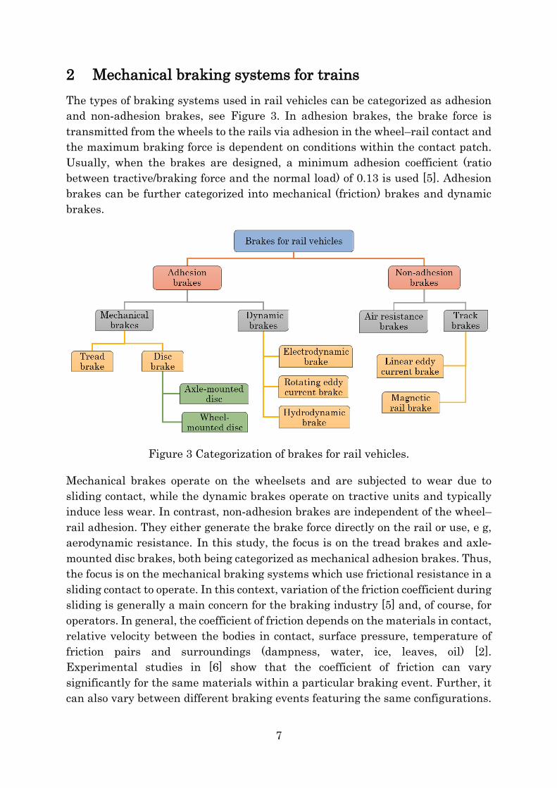
2 Mechanical braking systems for trains The types of braking systems used in rail vehicles can be categorized as adhesion and non-adhesion brakes, see Figure 3. In adhesion brakes, the brake force is transmitted from the wheels to the rails via adhesion in the wheel–rail contact and the maximum braking force is dependent on conditions within the contact patch. Usually, when the brakes are designed, a minimum adhesion coefficient (ratio between tractive/braking force and the normal load) of 0.13 is used [5]. Adhesion brakes can be further categorized into mechanical (friction) brakes and dynamic brakes.
Figure 3 Categorization of brakes for rail vehicles.
Mechanical brakes operate on the wheelsets and are subjected to wear due to sliding contact, while the dynamic brakes operate on tractive units and typically induce less wear. In contrast, non-adhesion brakes are independent of the wheel–rail adhesion. They either generate the brake force directly on the rail or use, e g, aerodynamic resistance. In this study, the focus is on the tread brakes and axle-mounted disc brakes, both being categorized as mechanical adhesion brakes. Thus, the focus is on the mechanical braking systems which use frictional resistance in a sliding contact to operate. In this context, variation of the friction coefficient during sliding is generally a main concern for the braking industry [5] and, of course, for operators. In general, the coefficient of friction depends on the materials in contact, relative velocity between the bodies in contact, surface pressure, temperature of friction pairs and surroundings (dampness, water, ice, leaves, oil) [2]. Experimental studies in [6] show that the coefficient of friction can vary significantly for the same materials within a particular braking event. Further, it can also vary between different braking events featuring the same configurations.

8
2.1 Tread brake
Tread (block) brakes are still one of the most common braking systems on railway vehicles. Tread braking is the ordinarily used system on freight wagons and is also common on passenger trains. Often, but not necessarily, tread brakes are used in combination with disc brakes and/or electrodynamic brakes. The tread braking action is carried out by pressing the brake blocks against the tread of a wheel. In addition, the tread is also in rolling contact with the rail. Tread brakes are simple, inexpensive and lightweight and are also easy to install, maintain and replace. They may also help in improving the wheel–rail adhesion by increasing the roughness of the wheel tread and removing contaminants [7]. The drawback to this is that the increased wheel tread roughness may increase rolling noise emissions. This is especially the case for wheels equipped with cast iron brake blocks [2]. The vehicle can be equipped with four different standard block configurations, as illustrated in reference [6]. The brake blocks are commonly manufactured from cast iron, organic composite, or sinter materials. The heat generated during braking is mainly taken by the wheels. In the case of severe braking, this can constitute a safety problem [3]. Moreover, damage and excessive wear of the wheel tread can occur due to severe braking [7].
2.2 Disc brake
Disc brakes are often used in passenger trains and always in high-speed trains. In disc brakes, the brake effort is created by the friction between brake lining (pads) and brake disc. Axle-mounted brake discs are employed on trailer bogies, where two or three discs (or even more) can be installed on a single axle depending on the application. On motor bogies, there is not enough space for axle-mounted discs due to the traction motor and gearbox. Instead wheel-mounted discs are utilized. Since the pad-disc friction is almost speed-independent, it is often prioritized to use disc brakes as the basic mechanical brake system for vehicles running at 160 km/h and above [9]. Commonly used materials for brake discs are grey cast iron, nodular cast iron and cast steel [5]. Friction materials used in brake pads are either organic composite or sintered. Noise levels are normally lower than for tread braking. Disc brake systems are, however, heavier and more expensive to install and maintain than block brake systems. Under severe braking conditions, brake discs may experience excessive wear and other forms of damage [4].

9
3 Phenomena – experiments and analyses This chapter covers phenomena studied in this thesis. The descriptions of the phenomena are followed by overviews of experimental and numerical analyses performed.
3.1 Braking temperatures
During mechanical braking, where two bodies are forced into sliding contact, a major part of the frictional energy is transformed into heat at the area of contact (and an insignificant part is transformed into particle removal and plastic deformation). The total heat generated will be divided between the two bodies in contact. The resulting temperatures during braking can cause deformations and build-up of stresses (both during and after braking) and are thus of main importance.
At tread braking, frictional heat generated from braking causes axial displacements of the wheel rim (change of gauge) during braking. For severe braking also residual displacements and residual deflections develop after braking. These displacements and residual tensile stresses in the wheel rim must be below specified limits if the tread-braked wheel design should be approved for revenue service. Tread-braked wheels for freight vehicles can be exposed to high braking loads for long duration at gradient braking, so-called drag braking. There are standards/guidelines available regarding the thermal capacity of wheels at drag braking, see [8, 9]. Results in an earlier study [3] highlight the importance of temperatures for tread braked wheels. In particular, factors influencing the thermal capacity of tread braked wheels in metro applications were thoroughly analysed.
Also brake discs are designed on the basis of the maximum temperature which they can safely sustain during operation [10]. Heat generated at pad–disc contact causes temperature increase in the friction surfaces resulting in build-up of compressive stresses and wear. During cooling, tensile residual stresses may develop below the friction surface. This will promote cracking.
Dissipation of heat from frictional surfaces is equally important. A tread braked railway wheel is subjected to cooling from the rolling contact with the cold rail, so-called rail chill. For discs, air flow in disc vanes is important for the cooling characteristics of the disc, see for instance [11] and [12].
Another phenomenon that is of interest when studying brakes is frictionally induced thermoelastic instabilities (TEI), which may introduce locally high temperatures between friction pairs and cause formation of thermal hot bands or hot spots. Figure 4, shows an example of thermal hot bands detected on two brake

10
disc types studied in field. TEI arises when a sliding contact area is subjected to contact pressure above average. This area is then heated to a higher temperature than its surroundings and the material expands. TEI causes changes with respect to distribution, magnitude and localization of the contact pressure and surface temperature. Studies exist where TEI have been investigated for tread brakes [13] and disc brakes [14].
Figure 4 Thermal hot bands captured by thermocamera on two brake disc types studied in Paper E.
Experiments
Temperatures can be measured by using either thermocouples or by using a thermocamera. A thermocouple measures temperatures at a point. But if installed as a sliding thermocouple it can measure along a path on the contact surface. For a better overview of temperature pattern and the thermal gradients along the contact surface, a thermocamera is more useful. A drawback is that the temperature magnitude needs to be verified, due to varying emissivity.
Measuring braking temperatures was an important task in this thesis. The measurements were used as basis to calibrate thermal simulations models and for understanding the influence of temperature on other phenomena such as fatigue and wear. Planning and execution of temperature measurement setup for field experiments in Paper C and Paper E, was part of this thesis. Three different kinds of K-type thermocouples were used in the field tests: surface thermocouples [15], sliding contact thermocouples [16] and thin wire embedded thermocouples [17]. Figure 5 shows setup of thermocouples used in field experiments in Paper E. A 3-channel and a 6-channel temperature data logger (TC-Link, see [18]) were used to record temperature data. Data were logged in the internal memory of the data loggers and collected wirelessly by a receiver at regular intervals. In addition, a thermocamera (Optris PI 160, see [19]) was used to record movies. The thermocamera was triggered when disc temperatures reached 80 °C.

11
Figure 5 Set-up of sliding thermocouples for measuring disc temperatures (left) and of thin wire embedded thermocouples for measuring pad temperatures (right) in field experiments in Paper E.
In Paper A and Paper D, thermocouples were used along with a thermocamera to measure the tread and rim temperatures on a full-scale brake rig setup (see Figure 6) situated at RTRI, Tokyo (Japan). Thermocouples were installed at a depth of 10 mm below the tread surface below the wheel–block contact. Detailed information about experimental set-up and procedure is given in [20].
Figure 6 Set-up of RTRI brake rig employed in tests. From Paper A.

12
Thermal analysis
During braking, the frictional heat generated at the area of contact is partitioned between blocks/pads and wheel/disc. The heat flux generated between blocks/pads and wheel/disc is calculated as
𝑞𝑞brake = 𝜇𝜇𝜇𝜇𝜇𝜇 (1)
where 𝜇𝜇 is the coefficient of friction, 𝜇𝜇 is the contact pressure and 𝜇𝜇 is the sliding speed. In tread brakes, heat is further conducted from the hot wheel into the cold rail. Average temperature of the wheel can be obtained by accounting for the heat partitioning between brake blocks, wheel and rail [6]. In a simplified approach, the temperature distribution on the wheel is computed presuming an evenly distributed heat flux over the wheel–block contact area using the heat partitioning model developed in [6, 21] including influence of rail chill [22]. The model, which is extensively used in Paper A, Paper B, Paper C and Paper D, is based on the third-body concept [23], and accounts for the temperature jump at the interface between two bodies in contact. For thermal analyses of disc brakes, the model is adapted accordingly in Paper E. In addition, dissipation of heat to the surroundings by convection and radiation is accounted for based on the classical formulae [24].
𝑞𝑞conv = −ℎconv𝐴𝐴s(𝑇𝑇 − 𝑇𝑇∞) (2) 𝑞𝑞rad = −𝜀𝜀𝜀𝜀𝐴𝐴s(𝑇𝑇4 − 𝑇𝑇∞4) (3)
Here 𝑇𝑇 [K] is the absolute temperature, 𝑇𝑇∞ [K] a reference temperature (ambient temperature), ℎconv the convection heat transfer coefficient, 𝜀𝜀 the Stefan–Boltzmann constant, 𝐴𝐴s the exposed surface area, and 𝜀𝜀 the emissivity. Figure 7 shows an example of thermal analysis for a wheel and a disc surface.
Figure 7 Example of calculated temperature distribution [°C] for a sector of a wheel (left) and a segmented brake disc (right) as evaluated by 3D FE analyses.

13
3.2 Thermomechanical fatigue
Both tread brakes and disc brakes are exposed to thermomechanical loads but the loads are acting in somewhat different ways. At tread braking, the wheel experiences mechanical loads from wheel–rail contact, centrifugal loads from rotation and thermal loads from braking. This means that the wheel web (and rim) must be designed for accommodating both stresses introduced by mechanical loads and stresses induced by increased temperatures from repeated braking cycles. This was investigated in the thesis [3]. A global fatigue failure of the wheel means a direct risk of derailment. Moreover, in the wheel–rail contact, the wheel tread experiences rolling contact loads, which may lead to rolling contact fatigue (RCF) damage in the wheel tread. Here, a combination of thermal and residual stresses resulting from braking, may increase RCF, see [7] and [25]. At disc braking, a brake disc experiences mechanical loads by the friction loads applied via brake callipers onto the disc surface, resulting in a mechanical torque but also in thermal stresses due to the temperature increase. For normal braking, the mechanical loads due to applied pressure and frictional forces are much lower in magnitude than the thermomechanical stresses resulting from the thermal loading. During braking, compressive stresses will build up near the friction surface of the discs and after plastification residual tensile stresses may develop during cooling. Repeated (or extreme) brake cycles may result in cracking [4].
Wheel tread damage calls for premature machining of wheels, which shortens their expected service life [26]. For railway wheels, tread damage can be removed by machining unless the minimum wheel diameter is reached, but for brake discs cracking this often requires disc replacement. In addition, the presence of TEI is important since it generates elevated temperatures on the frictional surfaces and produces additional damage [27]. Figure 8 provides illustrations of different types of damage in brake discs and on wheel treads, with indication of different types of RCF damage, see [1] and [28] for more details. In [29], a detailed description can be found on different types of tread damage.
Figure 8 Illustration of (left) different types of damage in brake discs and (right) zones for RCF on wheel tread. Left figure from [28].

14
Experiments
In Paper A, crack formation (initiation and propagation) at a wheel tread surface was measured every tenth brake cycle. Surface inspections were conducted with a liquid penetrant method and a magnetic particle method. In the field studies in Paper C and Paper E, no RCF tread damage nor disc cracks were observed for the studied wheels and discs.
Thermomechanical analysis
To simulate the impact on the wheel tread from combined thermal and mechanical loading, as imposed by braking and rolling contact, a 3D computational framework is established in Paper A. This framework was further utilized in Paper B and Paper D. The FE modelling involves sequential thermal and mechanical analyses conducted in three steps, see also Figure 9,
1. Heat partitioning between brake block, wheel and rail during stop braking is accounted for in axisymmetric thermal analyses using models developed in [4, 5].
2. Wheel–rail contact is simulated for an indentation type of loading using a detailed FE model to find local contact pressure distribution.
3. Wheel temperature histories, and mechanical rolling contact stresses, are applied as loads in a 3D structural analysis.
Further, the material response of the wheel is evaluated by studying the evolution of the total effective plastic strain at the most critical region on the wheel tread.
Figure 9 Schematic illustration of the steps followed for a sequential structural analysis of wheel tread performance. Outputs of the analyses are given in italics.
Heat partitioning
Wheel–rail contact "indentation" analysis
Thermal analysis
Structural analysis
Wheel–rail contact loading parameters Heat flux
Tread temperatures
Tread temperatures, temperature gradient
15
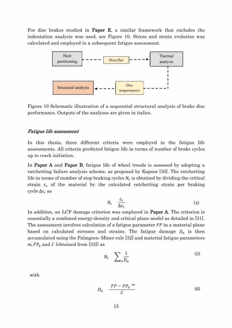
For disc brakes studied in Paper E, a similar framework that excludes the indentation analysis was used, see Figure 10. Stress and strain evolution was calculated and employed in a subsequent fatigue assessment.
Figure 10 Schematic illustration of a sequential structural analysis of brake disc performance. Outputs of the analyses are given in italics.
Fatigue life assessment
In this thesis, three different criteria were employed in the fatigue life assessments. All criteria predicted fatigue life in terms of number of brake cycles up to crack initiation.
In Paper A and Paper B, fatigue life of wheel treads is assessed by adopting a ratchetting failure analysis scheme, as proposed by Kapoor [30]. The ratchetting life in terms of number of stop braking cycles 𝑁𝑁r is obtained by dividing the critical strain 𝜀𝜀c of the material by the calculated ratchetting strain per braking cycle ∆𝜀𝜀r as
𝑁𝑁r =𝜀𝜀c∆𝜀𝜀r
(4)
In addition, an LCF damage criterion was employed in Paper A. The criterion is essentially a combined energy-density and critical plane model as detailed in [31]. The assessment involves calculation of a fatigue parameter 𝐹𝐹𝐹𝐹 in a material plane based on calculated stresses and strains. The fatigue damage 𝐷𝐷n is then accumulated using the Palmgren–Miner rule [32] and material fatigue parameters 𝑚𝑚,𝐹𝐹𝐹𝐹0 and 𝐶𝐶 (obtained from [33]) as
𝑁𝑁f = �1𝐷𝐷n𝑛𝑛
(5)
with
𝐷𝐷n =(𝐹𝐹𝐹𝐹 − 𝐹𝐹𝐹𝐹0)𝑚𝑚
𝐶𝐶 (6)
Heat partitioning
Thermal analysis
Structural analysis
Heat flux
Disc temperatures

16
For assessing fatigue life 𝑁𝑁f of brake discs in Paper E, a version of the Smith–Watson–Topper (SWT) criterion suitable for cast iron (based on [34]) is used
𝜀𝜀max∆𝜀𝜀m
2= 𝐼𝐼SWT(𝑁𝑁f)𝑆𝑆SWT (7)
Here 𝜀𝜀max is the maximum stress and ∆𝜀𝜀m is the mechanical strain range. Parameters 𝐼𝐼SWT and 𝑆𝑆SWT are constants obtained from [35], obtained from isothermal and thermomechanical fatigue experiments.
3.3 Wear
For the brakes, wear is normally defined as loss of material from a contact surface. For wheel–rail contact surfaces, displacement of material (plastification) can be perceived as wear. Wear of a material can be due to a number of different mechanisms or modes, see [36] for details. Important is that maintenance schedules for trains generally are based on wear predictions. Preferably, maintenance of different components should be performed at the same intervals. This means that unexpected variations in wear rates of a single component can cause large costs. At wear inspections, variations in wheel flange height Sh, width Sd and inclination qr, and in disc thickness are monitored.
A wheel tread wears due to the sliding contact between block and wheel and due to the rolling contact between wheel and rail. Wheel wear affects the “equivalent conicity”, which is a function of wheel and rail shapes, used to quantify the geometric interaction between wheel and rail profiles. A controlled “equivalent conicity”, is important for the safe and comfortable running of a wagon. Chapter 6 in [29] provides a detailed overview on tread wear under wheel–rail contact. Sufficiently high uniform wear rate can be beneficial as it may remove surface cracks introduced by RCF. This sufficiently high wear rate is generally referred to as the “magic wear rate” [37].
Discs wear mainly due to sliding contact between pad and disc. In addition, discs wear due to corrosion. It is usually desired that wheel treads and discs wear uniformly over the nominal frictional contact surface during braking. Sometimes variation in applied pressure and resulting temperatures might lead to non-uniform wear, also known as hollow wear. Figure 11 shows an example of a disc with non-uniform wear and Figure 12 shows hollow wear for a wheel tread.

17
Figure 11 A sector cut out from a railway disc with dashed lines indicating initial disc profile.
Figure 12 Illustration of hollow wear on wheel tread (from [38]).
Experiments
In the current thesis, wear of friction pairs (block/wheel and pad/disc) was measured in the field experiments in Paper C and Paper E, respectively. A high precision scale was used to measure wear of brake blocks and pads and wear was quantified in terms of mass loss. Wheel wear measurements (performed by the train operators) in the form of change in wheel flange height were used. In Paper D, wear of the wheel tread was monitored using a Miniprof (a device commonly used to measure exact wheel wear in experiments) in full-scale brake rig experiments to reveal the wear distribution on the tread. In Paper E, disc wear profiles were measured using the laser device CALIPRI and results were presented as volumetric wear. Figure 13 shows some measured disc profiles. There is a noticeable difference in both wear magnitude and wear distribution for the two discs, with apparent higher wear towards the inner disc radius.

18
Figure 13 Measured profiles of the reference brake discs for three intervals during field experiments in Paper E. Here the vertical axis corresponds to the radial disc coordinate, where “0 [mm]” corresponds to the outer radii of the disc. The horizontal axis corresponds to the reduction in disc thickness [mm].
Wear analysis
The commonly used method for predicting wear is Archard’s law [39]. In Paper C, a modified version described in [40] was used to calculate the wheel tread wear (due to tread braking) and block wear:
�̇�𝜔 = 𝑘𝑘w𝜇𝜇𝜇𝜇𝜇𝜇 (8) Here the wear rate �̇�𝜔 [m/s] is proportional to the contact pressure 𝜇𝜇 [N/m2], the sliding velocity 𝜇𝜇 [m/s] and the wear coefficient 𝑘𝑘w [m2/N]. In Paper C, 𝑘𝑘w for brake blocks was adopted from an earlier pin-on-disc study [41] as a temperature-dependent parameter along with a scaling factor 𝑘𝑘field introduced to match wear measured in field experiments. Wear rates from pin-on-disc studies of different brake block materials subjected to different temperatures are shown in Figure 14.
For the wheel tread, the wear coefficient 𝑘𝑘w was calibrated directly from field experiments and assumed to be temperature-independent. Wear was quantified in relation to both running distance and brake energy. In addition, wear of the wheel tread due to wheel–rail contact was assessed based on the USFD method [42]. In Paper D, tread wear due to braking was estimated (using 𝑘𝑘w calibrated in Paper C). Here also tread plastification due to wheel–rail contact was studied. Measured total wear was analysed as a product of wear coefficient and brake energy in Paper E for both brake pads and discs using data from field tests.

19
Figure 14 Measured wear rates for five brake block materials in pin-on-disc tests. The materials are organic composites OC1–OC3, cast iron and sinter. Results from [41].

20
4 Summary of appended papers 4.1 Paper A
Thermal cracking of railway wheel treads due to tread braking is studied by full-scale brake rig experiments and finite element simulations. The main goal is to develop a methodology to simulate the combined loading of the wheel tread under rolling contact and tread brake loads due to stop braking. The outcome of these simulations can be used to perform fatigue life predictions. To this end, it is noted that the wheel tread material is subjected to simultaneous mechanical and thermal loads due to rolling contact and tread braking, respectively. Full-scale tests featuring three series of repeated stop braking cases have been performed in a brake rig featuring a tread braked wheel that is in rolling contact with a so-called rail-wheel. From test rig experiments, it is observed that cracks appeared in the area on the wheel tread that is traversed by the wheel–rail-wheel contact. Further, sintered brake blocks result in shorter wheel life in comparison to organic composite brake blocks.
The brake rig experiments have been simulated numerically in a sequential thermomechanical analysis. In particular, the effect of “hot bands” on the tread as indicated by the experimental findings is accounted for. Stresses induced by heat from braking, as well as from tractive rolling contact loading on the tread, are considered. The mechanical response of the wheel material ER7 is simulated using an elastoplastic material model calibrated against data from cyclic experiments at room temperature and up to 625 °C. Finally, a methodology for predicting fatigue life with respect to ratchetting failure is established. It is found that FE simulation results of estimated accumulated plastic strains just below the tread, compared to a critical ratchetting strain for crack initiation, can successfully capture the experimental results.
4.2 Paper B
In revenue traffic, the running mode of a train varies and the operational parameters will influence the life of the wheel treads. To prevent excessive damage, it is therefore important to understand at which operational conditions wheel tread damage becomes unacceptable. The study aims to find limits for tread braking with respect to the influence on RCF of the wheel tread when subjected to repeated stop braking. A parametric study, using 3D FE simulations and involving operational parameters such as axle load, maximum vehicle speed, deceleration, brake block material and initial wheel temperature, is carried out for a new wheel (i e, having maximum wheel diameter and thick rim) with an S-shaped web.

21
Additional analyses investigate influence of wheel geometry by studying a wheel with a straight web and a wheel with a thin (worn) rim. The effects of simultaneous thermal loading from wheel–block frictional contact during braking and mechanical loading, due to the traversing wheel–rail rolling contact, are studied using the methodology developed in Paper A. Ratchetting fatigue life is evaluated in the wheel tread region for the studied brake load cases. The results show that high tread temperatures, in particular temperatures above 450 °C, have a strong detrimental influence on ratchetting strains and the RCF formation and, hence, on the thermomechanical capacity of the wheel tread. On the other hand, it is found that for braking temperatures between 300 °C and 375 °C, the fatigue resistance is increased due to strain hardening effects. In addition, the parametric study points towards actual braking load cases that can give such temperatures in terms of initial speeds, axle loads, etc. The web design (straight or S-shaped) will not affect tread fatigue life, and related crack formation, whereas a reduction in wheel rim thickness promotes wheel tread ratchetting due to increased flexural stresses from the mechanical wheel–rail contact loading.
4.3 Paper C
Field experiments were carried out for a commuter train in revenue service equipped with cast iron and organic composite brake blocks. Temperatures of wheel tread, wheel web and brake blocks were recorded together with wear of wheel treads and brake blocks. Measured temperatures were used for calibrating a thermal model (by tuning heat partitioning factors pertaining to the wheel and block interface and convection cooling parameters) used to predict wheel and block temperatures. A temperature-dependent wear model based on pin-on-disc experiments was employed to predict wear of cast iron and organic composite brake blocks. Numerically predicted temperatures were employed as input data. It is found that a wear rate adaption factor is required for producing a simulated wear that is in agreement with results from field experiments. This factor is tentatively motivated by the presence of thermoelastic instabilities at full-scale braking that cannot be found at small-scale testing, Wheel tread wear is assessed as a change in flange height for both powered and trailing wheels. For the studied train it is found that the levels of annual total wear of the two wheels are of similar magnitudes.
Modelling of the tread wear originating from block–wheel contact and wheel−rail contact, combined with a comparison towards measured wear magnitudes, makes it possible to distinguish the wear from these two tread contacts. It is found that for the powered wheels wear induced by the wheel–rail contact and the block–wheel contact have equal importance. In contrast, wear emanating from the block–wheel contact is dominating for the trailer wheels.

22
4.4 Paper D
In this study, wear and plastic deformation of a wheel tread surface at constant temperature rolling has been studied by employing a combination of brake rig experiments and simulations. The focus is on tread plasticity, specifically the surface deformations of the tread resulting from the rolling contact during braking in combination with wear due to braking. Full-scale brake rig experiments have been performed to quantify tread plasticity and tread wear during sequences of constant temperature rolling at 200 °C, 250 °C, and 300 °C, at a wheel–rail-wheel contact load of 60 kN. During the experiments, temperatures were recorded using three thermocouples fitted 10 mm below the tread surface. Measured temperature data from the thermocouples and a thermocamera point towards the presence of hot spots on the wheel tread. After the braking sequences the wheel profiles were measured using a Miniprof device. Experiments at 300 °C constant temperature rolling were simulated and the pertinent tread plastification was predicted. Finally, tread wear introduced by braking and in particular the influence of rolling contact plasticity on the tread profile evolution are predicted and compared to measured wear.
4.5 Paper E
Field experiments were carried out for a postal wagon equipped with two different friction pairs. One consists of an enhanced grey cast iron “segmented” brake disc (friction rings built from five identical sectors) with sinter material brake pads. Another consists of a standard grey cast iron “reference” disc with organic composite brake pads. During revenue service with speeds up to 160 km/h, temperatures of brake discs and brake pads were recorded along with train braking data in the form of train speed, friction forces and pneumatic brake pressures. Wear of discs and pads were measured intermittently by use of a laser scanning device and precision scales, respectively. Temperature distributions over disc friction surfaces were recorded using a thermocamera. Simulation models for predicting brake disc and pad temperatures were established. Heat partitioning factors pertaining to the disc and pad interface and convection cooling models were calibrated using data acquired for the two studied friction pairs based on an assumption of spatially uniform heat flux generation between disc and pads, although data from the thermocamera reveals presence of a single thermal hot band for the reference disc and of two thermal hot bands for the segmented disc. Thermomechanical behaviour of the two brake disc types is simulated for a simplified load case of uniform deceleration from maximum speed at maximum allowed axle load for the vehicle. From these simulations, fatigue lives are

23
estimated. For the studied stop braking cycle, the segmented brake disc has a two times longer calculated fatigue life (until initiation of cracks on the brake disc friction surfaces) than the reference brake disc. This is a consequence of the reduced build-up of residual tensile stresses (in the circumferential direction) after braking and cooling down. Wear measurements indicate that the disc wear is six times lower for the segmented disc than for the reference disc. The organic composite brake pads on the reference disc had four times higher wear than the sintered brake pads used with the segmented disc. Overall, the segmented brake disc assembly showed a better performance than the reference disc assembly in terms of temperature, fatigue life and wear.

24
5 Concluding remarks In Paper A, a methodology to simulate the conditions during full-scale brake rig experiments is presented. The brake rig experiments were performed with repeated stop braking cycles using sintered brake blocks and organic composite brake blocks. During the experiments, the wheel was subjected to thermomechanical loading caused by the combined tread braking and wheel–rail contact loads. In the experiments, the occurrence of TEI with locally higher tread temperatures was observed. The TEI are here caused by sintered brake blocks while the organic composite brake blocks usually produce an evenly distributed temperature on the wheel tread. From the test rig experiments, it is observed that cracks appeared in the area of the wheel tread that is traversed by the wheel–rail-wheel contact. It is found that braking with sintered brake blocks results in shorter time to tread crack initiation in comparison to braking with organic composite brake blocks. This is explained by the presence of local high temperatures on the wheel tread due to the TEI phenomenon. The TEI is accounted for in the thermal FE analysis by prescribing simplified thermal patterns on the wheel tread. To perform the structural FE analysis, a material model with a combination of non-linear isotropic and kinematic plastic hardening, was calibrated against data from cyclic strain-controlled experiments of ER7 steel at different temperatures. In the structural FE analysis, fatigue of the tread material was predicted by a ratchetting type of criterion and with an LCF damage criterion. The results indicated that the calculated LCF damage was lower than the ratchetting damage and that it could not predict the noticed reduction in life for more severe braking cycles. The predicted number of brake cycles to crack initiation presuming a critical ratchetting strain 𝜀𝜀c of approximately 1.6 was found to generate good correspondence with brake rig results. The results indicate that temperatures higher than about 450 °C lead to considerable increase in the ratchetting strain which causes shorter fatigue lives of the wheel for the stop braking cases considered here. On the other hand, in the temperature range 300 – 400 °C, a lower ratchetting damage is predicted due to the influence of dynamic strain ageing of the material.
In Paper B, the influence of important operational parameters such as axle load, maximum vehicle speed, deceleration, block material, wheel web design, wheel rim thickness, initial wheel temperature and friction coefficient between wheel and rail was investigated using the methodology developed in Paper A. Fatigue lives were predicted using the same ratchetting criterion. The results of the parametric study show influences of varying operational parameters on the peak braking temperatures and rolling contact loads. Also in this study, the predictions indicate that for loading conditions that result in temperatures higher than 450 °C, a substantial decrease in the ratchetting life of the wheel tread is expected. However, for temperatures in the range 300 – 375 °C the fatigue life is increased relatively.

25
The wheel web design was found not to influence the ratchetting life for identical operational conditions. In contrast, a wheel with reduced wheel rim thickness is more prone to ratchetting and crack formation than a new wheel for the same operational conditions. This is due to the higher wheel rim flexibility and a slight increase in temperatures. The results imply that a worn wheel in revenue service, which has a thin rim (resulting from consecutive machining and tread wear) and also a smaller wheel rolling diameter than a new wheel, will have an even lower fatigue life than the thin rim case considered in the present study. The reason is that the temperatures of the wheel would be even higher due to the more frequent heating resulting from the smaller wheel diameter.
In Paper C, temperatures of wheels and brake blocks and also wear of brake blocks and wheel treads were studied for a trainset by a combination of field experiments and numerical simulations. A motor car equipped with cast iron brake blocks and a driving trailer car equipped with both organic composite and cast iron brake blocks were instrumented. Measured data from the field experiments were used to calibrate a thermal model and to calculate temperature fields in the wheel treads, wheel webs and brake blocks. The calibrated thermal models were then used to predict the wheel and block temperatures during the long-term tests which were used for further wear assessment. The calibration of the wear models was made by comparison to measured wear data. A scaling factor 𝑘𝑘field for wear of brake blocks was introduced and calibrated using a temperature-dependent wear model. Wear of brake blocks was presented as mass wear in relation to both distance and brake energy. Tread wear was quantified in terms of change in flange height. The wear, assessed at the rolling circle, was separated into wear from the wheel–rail contact, assessed using the USFD method (another version of the 𝑇𝑇𝑇𝑇 method) and wear from tread braking. Wear rates from wheel–rail contact and 𝑇𝑇𝑇𝑇/𝐴𝐴 magnitudes were found to be low and corresponded well to twin disc tests in a mild wear regime. The remaining part of the wear introduced by tread braking was calculated using Archard’s law. A temperature-independent wear model for assessing the tread wear due to wheel–block contact at braking was calibrated. The annual total tread wear for both cars was similar in magnitude. The wear due to wheel–block contact was about 55% of the total measured wear for the motor car. For the driving trailer car it was found to be about 96%. In the end, the relation between braking energy and tread wear due to wheel–block contact was found to be rather similar for the two car types. This is reflected in the calibrated wear rate parameters for the tread wear due to the wheel–block contact that shows a 4% variation between the cars. Finally, wear at the rolling circle due to pure rolling on tangent track was estimated. It was found to constitute a source of error that is relatively small as compared to the calculated wheel–block wear.
Paper D investigates wear and plastic deformation of wheel tread surface at constant temperature rolling by use of a combination of brake rig experiments and

26
simulations. During the experiments, temperatures were recorded using thermocouples fitted 10 mm below the tread surface over the width of wheel–block contact. Measured temperature data from the thermocouples indicated the presence of hot spots on the wheel tread. Wheel profiles were measured using a Miniprof device. Tread wear due to braking was also predicted using a wear model calibrated in Paper C. Experiments at 300 °C constant temperature rolling were simulated using a methodology adopted from Paper A. The simulation results indicate that when temperature increases, there is a run-in with increased plastic deformations during the first wheel revolution. Further, by the last mechanical passage in each time instance the surface depression is negligible for tread temperatures below some 400 °C. For surface temperatures above 415 °C, ratchetting type of surface depression was observed for each repeated load cycle. In total, plastic deformation of the tread can be estimated in an average sense by the current simulation methodology for constant temperature rolling at 300 °C. For the experiment at 300 °C, the sum of simulated tread plastification and calculated tread wear is close to the measured surface depression.
In Paper E, field experiments are performed for a postal wagon equipped with axle-mounted brake discs operating in revenue traffic with speeds up to 160 km/h. Two different types of brake discs and brake pads are instrumented. Temperatures were recorded along with train braking data in the form of train speed, friction forces and pneumatic brake pressures. Temperature profiles for both disc types were also measured using a thermocamera. Measured train data are used as input to the thermal model and calibration is performed against measured temperatures. Temperatures predicted using the calibrated thermal model show good agreement with measured temperatures. Predicted pad temperatures are close to measured temperatures, although the cooling needs to be reduced slightly (tentatively by reducing convection scaling factor 𝑘𝑘Nu for the pads) to improve calibration. Monitoring indicates the presence of thermal hot bands; a single hot band for the reference brake disc and two hot bands for the segmented brake disc.
The calibrated thermal models for the discs are further employed in a thermomechanical analysis for a load case corresponding to the maximum load capacity of the wagon. Maximum tensile stresses in the circumferential direction of the brake discs are evaluated. Stress and strain evolutions are evaluated and employed in fatigue assessments. The fatigue analyses show that resistance against crack initiation is higher for the segmented disc than for the reference disc, with a fatigue life increase by a factor of about two. Wear of discs and pads were measured intermittently and results are presented in relation to running distance and brake energies. The results show that the friction pair on the reference disc assembly has higher wear rates (four times higher for pads, and six times higher for discs) than the segmented brake assembly. This is reflected in the calibrated values of wear coefficients 𝑘𝑘wdisc and 𝑘𝑘w
pad. The reference disc showed a higher

27
tendency for hollow wear as compared to the segmented disc, which features a more uniform wear pattern. The segmented brake disc assembly showed a better performance than the reference disc assembly in terms of temperature, build-up of residual tensile stresses, fatigue life and wear.
28
6 Future developments Paper A and Paper B focus on RCF damage originating from wheel–rail rolling contact loads during tread braking at elevated temperatures. In the analyses, the wheel treads have been considered to be in a virgin state with no prior damage at the onset of braking. In Paper A, damage due to LCF and ratchetting at high temperatures were studied separately. For future work, the possibility to account for both of these damage types could be of interest in order to obtain a total combined damage for tread braked railway wheels. Additionally, load cases pertaining to effects of drag braking can be investigated.
The wear simulation methodology developed in Paper C for estimating wear of both brake blocks and wheel tread can be further improved by considering the tangential and creep forces due to curving. This will require multibody dynamic simulations. The study could also be complemented with results for higher braking temperatures and axle loads.
Use of a thermocamera can be helpful in detecting the temperature distributions and the presence of TEI on friction surfaces. It can be used together with thermocouples that can capture the local variations in temperatures. In Paper D, a thermocamera was used from side view capturing temperature variations on the wheel rim radially. Further in Paper D, additional studies can be performed for the experiments at 200 °C and 250 °C to further investigate tread plastification during braking.
Paper E can be enhanced by further utilizing data from the thermocamera to investigate the thermal hot bands during braking and their effect on the fatigue life assessment. Temperature data from the thermocamera could be compared with measured data from sliding and embedded thermocouples. More wear data should be collected which would provide a better understanding of disc wear. Further, the material model could be better adapted to the actual disc material to get a better overview of the disc performance. In addition, fatigue life predictions based on the Coffin–Manson criterion could be studied and compared to predicted fatigue lives in the current study. A parametric study on different types of load cases can provide a better overview of initiation of thermal cracking for the two types of discs studied here. Similar methods to those used in Paper E can also be used for assessing performance of brake discs on passenger trains.
Finally, results from all the above studies can be combined and utilized together to study load cases when the brake effort is distributed between different braking systems. Based on the known limitations of each sub-system, cost effective brake partitioning between braking systems can be designed.

29
References
1. A. Ekberg, B. Åkesson, and E. Kabo, Wheel/rail rolling contact fatigue – Probe, predict, prevent. Wear, 2014, 314(1), 2-12.
2. T. Vernersson, Tread braking of railway wheels – noise-related tread roughness and dimensioning wheel temperatures: field tests, rig measurements and numerical simulations, Doctoral Dissertation, Chalmers Applied Mechanics, Gothenburg (Sweden), 2006.
3. S. Teimourimanesh, Thermal capacity of railway wheels - temperatures, residual stresses and fatigue damage with special focus on metro applications, Doctoral Dissertation, Chalmers Applied Mechanics, Gothenburg (Sweden), 2014.
4. G.L. Gigan, On improvement of cast iron brake discs for heavy vehicles-Laboratory experiments, material modelling and fatigue life assessment, Doctoral Dissertation, Chalmers Applied Mechanics, Gothenburg (Sweden), 2015.
5. K. Bill and B. Breuer, Brake technology handbook, SAE International, Warrendale PA, 2008.
6. T. Vernersson, Temperatures at railway tread braking. Part 1: Modelling. Proceedings of the Institution of Mechanical Engineers, Part F: Journal of Rail and Rapid Transit, 2007, 221(2), 167-182.
7. S. Caprioli, Thermal impact on rolling contact fatigue of railway wheels, Doctoral Dissertation, Chalmers Applied Mechanics, Gothenburg (Sweden), 2014.
8. AAR-Manual-of-Standards, Manual of standards and recommended practices - Wheels and Axles. The Association of American Railroads, Washington DC, USA, 2004.
9. Technical approval of monobloc wheels – Application document for standard EN 13979-1. International Union of Railways (UIC), Paris, France, 67 pp.
10. P. Dufrenoy, Two-/three-dimensional hybrid model of the thermomechanical behaviour of disc brakes. Proceedings of the Institution of Mechanical Engineers, Part F: Journal of Rail and Rapid Transit, 2004, 218(1), 17-30.
11. M. Tirović and C. Galindo-Lopez, Convective heat dissipation from a wheel-hub-mounted railway brake disc. Proceedings of the Institution of Mechanical Engineers, Part F: Journal of Rail and Rapid Transit, 2008, 222(4), 355-365.
12. M. Tirović, Energy thrift and improved performance achieved through novel railway brake discs. Applied Energy, 2009, 86(3), 317-324.
13. D. Thuresson, Thermomechanics of block brakes, Doctoral Dissertation, Chalmers Applied Mechanics, Gothenburg (Sweden), 2006.
14. S. Panier, P. Dufrénoy, and D. Weichert, An experimental investigation of hot spots in railway disc brakes. Wear, 2004, 256(7–8), 764-773.

30
15. Omega Engineering Limited, Surface Thermocouple probe (SA1XL-KI-2M), Manchester, UK, 2018, https://www.omega.co.uk/.
16. Thermosense Limited, Type K Brake Disc Rubbing Style Thermocouple Sensor, Bourne End, UK, 2018, https://www.thermosense.co.uk/.
17. RS Components AB, RS PRO Type K Thermocouple (824-0506), Gothenburg, Sweden, 2018, https://se.rs-online.com/web/.
18. LORD Sensing Systems, Wireless Nodes, Williston VT, USA, 2018, www.microstrain.com.
19. Optris GmbH, Optris PI® 160 thermal imager, Berlin, Germany, 2018, www.optris.global.
20. K. Handa and F. Morimoto, Influence of wheel/rail tangential traction force on thermal cracking of railway wheels. Wear, 2012, 289(0), 112-118.
21. T. Vernersson, Temperatures at railway tread braking. Part 2: Calibration and numerical examples. Proceedings of the Institution of Mechanical Engineers, Part F: Journal of Rail and Rapid Transit, 2007, 221(4), 429-441.
22. T. Vernersson and R. Lundén, Temperatures at railway tread braking. Part 3: wheel and block temperatures and the influence of rail chill. Proceedings of the Institution of Mechanical Engineers, Part F: Journal of Rail and Rapid Transit, 2007, 221(4), 443-454.
23. N. Laraqi, Velocity and relative contact size effects on the thermal constriction resistance in sliding solids. Jouranl of Heat Transfer Trans. ASME, 1997, 119(1), 173-177.
24. J.P. Holman, Heat transfer, 8th edition, McGraw-Hill, New York, 1997.
25. K. Handa, Y. Kimura, and Y. Mishima, Surface cracks initiation on carbon steel railway wheels under concurrent load of continuous rolling contact and cyclic frictional heat. Wear, 2010, 268(1–2), 50-58.
26. J. Tunna, J. Sinclair, and J. Perez, A review of wheel wear and rolling contact fatigue. Proceedings of the Institution of Mechanical Engineers, Part F: Journal of Rail and Rapid Transit, 2007, 221(2), 271-289.
27. P. Dufrénoy, G. Bodovillé, and G. Degallaix, Damage mechanisms and thermomechanical loading of brake discs. European Structural Integrity Society, 2002, 29, 167-176.
28. W. Sawczuk, J. Kowalczyk, D. Ulbrich, and S. Kolodziejski, Non-destructive research of the friction surface of the brake discs in the aspect of braking process evaluation, in 19th World Conference on Non-Destructive Testing 2016. Munich, Germany.
29. R. Lewis and U. Olofsson, Wheel-rail interface handbook, CRC Press, Boca Raton (USA), 2009.

31
30. A. Kapoor, A re-evaluation of the life to rupture of ductile metals by cyclic plastic strain. Fatigue & Fracture of Engineering Materials & Structures, 1994, 17(2), 201-219.
31. Y. Jiang and H. Sehitoglu, A model for rolling contact failure. Wear, 1999, 224(1), 38-49.
32. S. Suresh, Fatigue of materials, 2nd edition, Cambridge University Press, UK, 1998.
33. O. Onal, D. Canadinc, H. Sehitoglu, K. Verzal, and Y. Jiang, Investigation of rolling contact crack initiation in bainitic and pearlitic rail steels. Fatigue & Fracture of Engineering Materials & Structures, 2012, 35(11), 985-997.
34. J. Fash and D.F. Socie, Fatigue behaviour and mean effects in grey cast iron. International Journal of Fatigue, 1982, 4(3), 137-142.
35. G. Gigan, V. Norman, J. Ahlström, and T. Vernersson, Thermomechanical fatigue of grey cast iron brake discs for heavy vehicles. Proceedings of the Institution of Mechanical Engineers, Part D: Journal of Automobile Engineering, 2019, 233(2), 453-467.
36. R.G. Bayer, Wear analysis for engineers, HNB Publishing, New York, 2002.
37. J. Kalousek and E. Magel, Achieving a balance: the magic wear rate. Railway Track & Structures, 1997, 93(5), 50-52.
38. A. Kapoor, I. Salehi, and A.M.S. Asih, Rolling Contact Fatigue (RCF), in Encyclopedia of Tribology, Q.J. Wang and Y.-W. Chung, Editors. 2013, Springer US: Boston, MA USA, 2904-2910.
39. J.F. Archard, Contact and rubbing of flat surfaces. Journal of Applied Physics, 1953, 24(8), 981-988.
40. T. Vernersson and R. Lundén, Wear of block brakes and disc brakes for repeated brake cycles. Proceedings 6th European Conference on Braking (JEF2010/6ème Conférence Européenne du Freinage), Lille, France, 2010, 19-27.
41. S. Abbasi, S. Teimourimanesh, T. Vernersson, U. Sellgren, U. Olofsson, and R. Lundén, Temperature and thermoelastic instability at tread braking using cast iron friction material. Wear, 2014, 314(1–2), 171-180.
42. J. Pombo, J. Ambrósio, M. Pereira, R. Lewis, R. Dwyer-Joyce, C. Ariaudo, and N. Kuka, Development of a wear prediction tool for steel railway wheels using three alternative wear functions. Wear, 2011, 271(1), 238-245.