Mechanical Behavior Notes-2009dweavergroup.ua.edu/uploads/4/8/9/0/48901279/n14.pdf · Dislocations...
24
Module #14 Module #14 Dislocations in Common Crystal Structures READING LIST DIETER: Ch. 5, Pages 154-160 Chs. 5 and 6 in Hull & Bacon Chs. 10-12 in Hirth & Lothe HOMEWORK From Dieter 5-1, 5-4, 5-5, 5-9
Transcript of Mechanical Behavior Notes-2009dweavergroup.ua.edu/uploads/4/8/9/0/48901279/n14.pdf · Dislocations...

Module #14 Module #14
Dislocations in Common Crystal Structures
READING LISTDIETER: Ch. 5, Pages 154-160
Chs. 5 and 6 in Hull & BaconChs. 10-12 in Hirth & Lothe
HOMEWORKFrom Dieter
5-1, 5-4, 5-5, 5-9

ObjectiveObjective
• The objective of this module is to present some of the dislocations observed in FCC, HCP and BCC crystal structures.
• This section is intentionally brief. More details can be found by consulting the reading list.
• We will not address ceramics or intermetallics here. They will be addressed separately.

Plastic Flow in GeneralPlastic Flow in General
• Slip occurs via glide
• Slip occurs on close-packed planes in close-packed directions
• Slip system = Slip plane + Slip direction

Slip in FCC CrystalsSlip in FCC Crystals
Each unit cell contains 4 {111} planesEach {111} plane contains 3 <110> directions
Thus, there are 12 slip systems in an FCC unit cell
Close-packed plane: 111
Close-packed directions on 111 : 110
Shortest lattice vectors: 1102
Dislocations usually glide on the basal plane with 1102
o
o
a
ab

RECALL: Dissociation of dislocationsRECALL: Dissociation of dislocations
• Because of energy considerations it is also possible for somedislocations to dissociate (split) into shorter segments. This is favorable in certain crystals (Ex., FCC).
• This is possible in close-packed crystals such as FCC and HCP where equilibrium positions are not the edges of the unit cell.
1 2 3
2 2 21 2 3
2 2 21 2 3
b b b
b b b
b b b
Will the reaction occur?
Yes if
No if
IMPORTANTElastic strain energy Gb2

• In this example, the separation into partial dislocations is energetically favorable. There is a decrease in strain energy.
• Separation produces a stacking fault between the partials.
Shockley Partial Dislocations in FCC crystalsShockley Partial Dislocations in FCC crystals
22 2
1012
2
2 1 1 1126 6
6 6
o oo
o o o
a
a
a a
a a
2101
2 2o oa a
b
6211
6 6o oa a
b
6112
6 6o oa a
b
A BC
A
B
C

“A” type (111) plane
“B” type (111) plane“C” type (111) plane
In an fcc lattice, slip occurs on (111) planes in <110> directions
ABCABCABCABC

“A” type (111) plane
“B” type (111) plane
1012oa
12
1012 2
o oa ab
The vector b1 represents the unit Burgers vectorHowever, there is a “simpler” path.
ABCABC | ABCABC

22 2
1012
2
112 21 16 6
6 6
o oo
o o o
a
a
a a
a a
Partial dislocation line
Partial dislocation line
Stacking Fault
3 2 1 16oa
b 2 112
6oa
b
ABCABC | ACAC | ABCABC
SF
Less energy is required if unit dislocation dissociates:

• AB represents a regular (un-extended) dislocation.
• BC and BD represent partial dislocations.
• The region between BC and BC represents the stacking fault. In this region, the crystal has undergone “intermediate” slip.
• BC + stacking fault + BD represents an extended dislocation.
• Extended dislocations (in particular screw dislocations) define a specific slip plane. Thus, extended screw dislocations can only cross-slip when the partial dislocations recombine. See the illustration on the next page.
• This process requires some energy.
2 3
2partial dislocationseparationshear modulus
SFEGb bSFE
dd
G
2 1126oa
b
3 2 1 16oa
b SLIPPED
UNSLIPPED
A
B
CD
101
121
$ $
12
1012 2
o oa ab
$
FCC CrystalSTACKING FAULTWidth = d

Extended DislocationExtended Dislocation[Partial Dislocation + SF + Partial Dislocation]
• An extended screw dislocation must constrict before it can cross slip.
1 1 102
b
(111) plane
(11 1) plane
Direction of motion
Cross-slip plane
(1) Extended
(2) Formation of constricted segment
(3) Cross-slip of constricted segment and separation into extended
(4) Slip of extended on cross-slip plane
(1) (2)(3)
(4)
Schematic illustration

• It is more difficult to re-combine wide stacking faults (i.e., those with large d).
• Cross-slip is more difficult in materials with low SFE. Thus high SFE materials will work harden more rapidly.
• We will address this in more detail when we discuss work hardening.
MaterialSFE
(mJ/m2)Faultwidth
StrainHardening
rate REASONSStainless Steel <10 ~0.45 High Cross slip is more difficult
Copper ~90 ~0.30 Med
Aluminum ~250 ~0.15 Low Cross slip is easier
See pages 74-79 in Hertzberg
2 3
2partial dislocationseparationshear modulus
SFEGb bSFE
dd
G
2 1126oa
b
3 2 1 16oa
b SLIPPED
UNSLIPPED
STACKING FAULTWidth = d
A
B
CD
101
121
$ $
12
1012 2
o oa ab
$
FCC Crystal

A
B BC
A A
AA
2 6 6110 211 121a a a
Geometry of close-packed planes appropriate for dissociation intoShockley partial dislocations. The large blue arrow corresponds to
while the small green arrows correspond to and .
Figure adapted from R.C. Reed, Superalloys: Fundamentals and Applications, (Cambridge University Press, Cambridge, 2006) p. 56.

Thompson Tetrahedron
Shows relationships of all total & partial ‘s in
FCC system.
[M.A. Meyers and K.K. Chawla, Mechanical Metallurgy, (Prentice-Hall, 1984) p. 249]

[M.A. Meyers and K.K. Chawla, Mechanical Metallurgy, (Prentice-Hall, 1984) p. 249]
BA = Bγ + γA
Convenient way to visualize dislocation
reactions in fcccrystals

Frank Partial dislocations in FCC crystalsFrank Partial dislocations in FCC crystals
• Formed by inserting or removing one close-packed {111} layer of atoms. This results in either an intrinsic or an extrinsic stacking fault.
• This results in an edge dislocation with a Burgers vector is normal to the {111} plane of the fault. This dislocation is sessile.
[Hull & Bacon]
[111]3oab

Interaction of dislocations on intersecting slip planesInteraction of dislocations on intersecting slip planes• Consider intersection (111) slip planes in an FCC lattice
1 1012ab
2 01 12ab
3 1102ab
(001)
(11 1)
(111)1 2
2 21
3
23
2 2
2
2
[101] [01 1]2 2
(11 1),
[110]2
(001(111)
4 4
)
4
,
oo o
b ba a
b
ba
b
a a
b
a
on on on
Lomer lock
1 [101]2ab
2 [01 1]2ab
3 [110]2ab
001 plane
11 1 plane
111 plane
x
y
z

Interaction of dislocations on intersecting slip planes• Consider intersection (111) slip planes in an FCC lattice.• <110> dislocations can separate into Shockley partials.
1 11
(11 1)
[101] [112][2 11]62 6
a bba
ba a
b
on
2 22
(111)
[01 1] [112][12 1]62 6
a bba
ba a
b
on
1 2
[211] [1 [12 16
]6
10]6
LCa ab ba a
ba
AT INTERSECTIONThis combination is known as a Lomer-Cottrell lock. It is termed a stair-rod dislocation and is sessile.
Figure adapted from I. LeMay, Principles of Mechanical Metallurgy, Elsevier (1981) p. 111
Lomer-Cottrell lock

Dislocations in Hexagonal CloseDislocations in Hexagonal Close--Packed CrystalsPacked CrystalsDislocations are similar to those in FCC crystals.
Close-packed plane: 0001
Close-packed direction: 1120
Shortest lattice vectors: 11203
Dislocations usually glide on the basal plane with 11203
o
o
a
ab
[Hull & Bacon, p. 102]
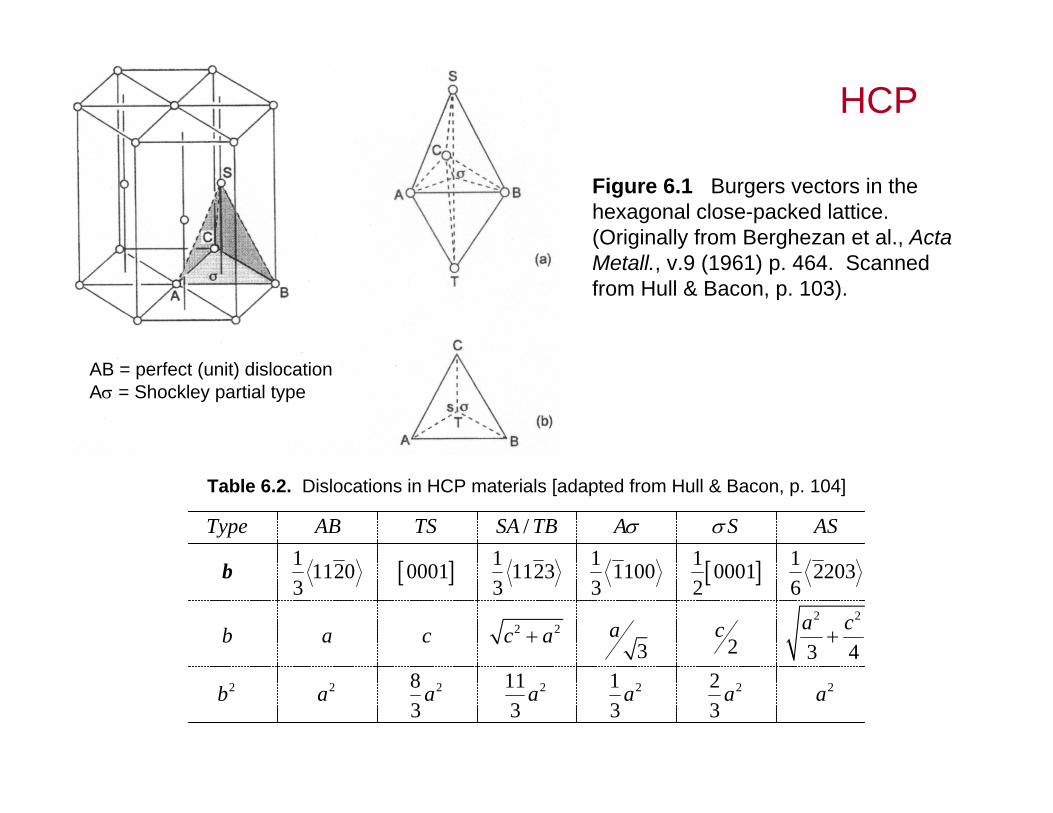
Figure 6.1 Burgers vectors in the hexagonal close-packed lattice. (Originally from Berghezan et al., ActaMetall., v.9 (1961) p. 464. Scanned from Hull & Bacon, p. 103).
Table 6.2. Dislocations in HCP materials [adapted from Hull & Bacon, p. 104]
2 2
2 2
2 2 2 2 2 2 2
/1 1 1 1 11120 0001 1123 1100 0001 22033 3 3 2 6
23 3 48 11 1 23 3 3 3
Type AB TS SA TB A S AS
a ca cb a c c a
b a a a a a a
b
AB = perfect (unit) dislocationA = Shockley partial type
HCP

HCPNonNon--basal slipbasal slip
• Can occur. Burgers vector is still:
• In Be, Mg, Cd and Zn, perfect dislocations dissociate into Shockley partials.
[Hull & Bacon, p. 105]
11203oab
2 22
1 1 11120 1010 01103 3 3
3 3a aa
2:b

Slip in BCC CrystalsSlip in BCC Crystals
Each unit cell contains 6 {110} planesEach {110} plane contains 2 <111> directions
Thus, there are 12 {110}<111> slip systems in an BCC unit cell.
Close-packed plane: 110
Close-packed directions on 110 : 111
Shortest lattice vectors: 1112
Dislocations usually glide on the basal plane with 1112
o
o
a
ab

Slip in BCC Crystals Slip in BCC Crystals –– contcont’’ddIn BCC slip can also occur on {112} and {123} planes in
<110> directions
Each unit cell contains 12 {112} planesEach {112} plane contains 1 <111> directionThus, there are 12 {112}<111> slip systems.
Each unit cell contains 24 {123} planesEach {123} plane contains 1 <111> directionThus, there are 24 {112}<111> slip systems.
Thus there are a total of 48 possible slip systems inBCC crystals

Dislocations in BodyDislocations in Body--Centered Cubic CrystalsCentered Cubic Crystals
• Slip on {110} is most prevalent.
• However, {112}, and {123} planes, but
• Three {110} planes intersect a [111] direction. Unit screw dislocations can easily move from one {110} to {123} and/or {211} planes resulting in wavy slip lines.
• Extended dislocations are uncommon.