Atomistic investigation of GFRP composites under chloride ...

271
KMUTNB Int J Appl Sci Technol, Vol. 8, No. 4, pp. 271–282, 2015
Mechanical Behavior Investigation of UHMWPE Composites for Pile Cushion Applications
Viewvana Tulatorn, Sirisart Ouajai, Rungsima Yeetsorn* and Noppavan Chanunpanich Department of Industrial Chemistry, Faculty of Applied Science, King Mongkut’s University of Technology North Bangkok, Bangkok, ThailandIntegrated Nano Research Center, King Mongkut’s University of Technology North Bangkok, Bangkok, Thailand
* Corresponding author. E-mail: [email protected] and [email protected] Received: 29 July 2015; Accepted: 14 August 2015; Published online: 6 October 2015© 2015 King Mongkut’s University of Technology North Bangkok. All Rights Reserved.
AbstractPresently, there is no specific guiding principle on the utilization of polymeric composites as a pile cushion pad. There is a prerequisite consequently to understand their mechanical behavior during a pile driving process. Hence, this article is concerned with the observations of mechanical behavior under cyclic loading application, compressive strength, coefficient of restitution, and permanent deformation of ultrahigh molecular weight polyethylene (UHMWPE) and activated carbon (AC) composites. UHMWPE/AC composites containing 1, 3, 5, 10 and 20 wt% of AC concentrations were prepared for accomplishing the aim. Prior to those characterizations, the composites were compression molded under 160ºC for various operating times (5 to 40 minutes). As a comparison to UHMWPE, applying AC into UHMWPE matrix significantly reduced the cycle time of the compression molding. Compressive strength at 80% deformation, tangent modulus and coefficient of restitution of UHMWPE were inferior to those properties of UHMWPE/AC composites. In terms of the coefficient of restitution, the coefficient values of composites were obviously higher than UHMWPE’s values. Moreover, the coefficient of restitution at 8,000 N/min of all samples was greater than a represented coefficient from the test at 2,000 N/min. UHMWPE/AC composites with 10 wt% of AC loading provided the best mechanically reversible performance. Experimental results also indicated that the mechanical property enhancement associated with an increase in UHMWPE’s molecular weight, while the creep strain of UHMWPE was affected by the applied amount of AC. Permanent deformation data illustrated that the increasing cycles of compression urged the deterioration as same as the results measured via cyclic compression testing. In overview, UHMWPE/AC composites showed a promise for future opportunities as a viable option in replacing a traditional material for manufacturing a pile cushion pad.
Keywords: UHMWPE, Pile cushion, Cyclic compression test, Coefficient of restitution, Pile driving, Creep test
Please cite this article as: V. Tulatorn, S. Ouajai, R. Yeetsorn, and N. Chanunpanich, “Mechanical Behavior Investigation of UHMWPE Composites for Pile Cushion Applications,” KMUTNB Int J Appl Sci Technol, Vol. 8, No. 4, pp. 271–282, 2015, http://dx.doi.org/10.14416/j.ijast.2015.08.001
1 Introduction
Building construction work is typically concerned with building structural loading and settlement requirements, geotechnical conditions, and specific site, therefore; the consideration for construction commonly dictates the use of deep foundations [1]. Pile driving
is a process which drives a pile into soil to deliver foundation support for buildings or other structures [2]. A pile driving system consists of various constituents that are exhibited in Figure 1. The pile driving process requires a cushioning element, called a cushion pad or a hammer cushion pad, for force transmitting and preventing a pile’s damage. The cushion pad is located

272
V. Tulatorn et al. / KMUTNB Int J Appl Sci Technol, Vol. 8, No. 4, pp. 271–282, 2015
inside a pile cap placed between the hammer and the pile [3]. The cushion pad serves four main purposes as follows: to distribute the impact load homogeneously over the surface of the pile head, to remove stress concentrations produced by pile head eccentricity, to attenuate the impulsive force of a ram, and to increase the impact time which is necessary for the penetration of a pile [4]. Conventional cushion pads are ordinarily made from hardwood, plywood, oak, or other hard materials. A material improvement for a cushion pad fabrication is necessary, because hardwood and hard materials have some disadvantages. The materials are difficult to remove from the pile cap, and they have short useful life. The short life time corresponds to the significant energy loss of the materials. This drawback can be observed from the coefficient of restitution as a following example; the hardwood has coefficient of restitution in the range of 0.25–0.50 over a life time for a pile cushion application [5], [6]. Polymeric materials; for instance, polyamide (thermoplastic), or phenolic resin (thermoset) have promising characteristics to be used as a cushion pad material, since they contribute coefficient of restitution within a range of 0.4–0.5 [5].
Plastics have the ability to be molded or machined easily, and can be also fabricated in terms of mass productions. A material for a plastic pile cushion must be strong to withstand the pounding and to transmit the driving force needed. Therefore, it should contain excellent impact strength, optimal reversibility after it is impacted, and optimal transmission of as much of the driving energy as possible to the pile [2].
UHMWPE is an interesting material for the production of a cushion pad, since it consists of long chains with molecular weight typically between 2 and 6 million [7], [8]. These long chains serve to transfer load effectively to the UHMWPE backbone strengthening
intermolecular force. This interaction contributes desired mechanical properties, such as 0.75 MPa/m2
of stress-crack resistance and 127 kJ/m2 of impact resistant [9], [10]. Conversely, UHMWPE is difficult to melt, due to its high molecular weight. There are two common deficiencies that can be observed: voids and particle boundaries deficient in diffusion by reputation [11]. The poor processability can be improved by introducing high thermally conductive fillers, for instance, activated carbon, carbon black, graphite powder, or carbon nanotubes [12] into the UHMWPE matrix. Thereby, activated carbon was selected to be a filler component of a UHMWPE/AC composite for enhancing its thermal stability and thermal conductivity [13]. The focus of this work is a preliminarily investigation of the mechanical behaviors of UHMWPE and AC composites related to requirements of the pile cushion pad. Mechanical tests including compressive strength, cyclic compressive loading, and creep were, therefore, determined in this work. The compressive strength of UHMWPE and UHMWPE/AC composites correspond to elastic micro-buckling, plastic micro-buckling in which the UMWPE matrix deforms plastically, filler crushing, buckle delamination, etc. [14] Cyclic loading test was performed relating to the mechanism of pile driving process. Cyclic loading can lead to fatigue failures resulting from the accumulation of plastic strain [15]. Additionally, the hysteresis from the cyclic loading corresponds to the quantity of energy loss during a cycle and relates to either viscoelasticity, or viscoplasticity [16]. Creep behavior indicates a time dependent plastic deformation that happens under stresses inferior to the yielding stress of a material. Thus, the effect of adding solid fillers as AC into polymer matrix on the creep behavior is regularly considered. The creep behavior is typically determined either in real-time or in short-time tests under various types of loading such as compression, tension, and flexure [17]. The tension creep test in short time was selected for this work. To accomplish the aim of this work, the UHMWPE/AC composites were prepared and compression molded. An experimental model was established to address the time-dependent component of the hysteresis associated with the compressive loading/ unloading of composite specimens and creep test. The approach of this research would provide direction for further improvement of polymeric cushion pad production.
Figure 1: Schematic of a pile driving system.
273
V. Tulatorn et al. / KMUTNB Int J Appl Sci Technol, Vol. 8, No. 4, pp. 271–282, 2015
2 Composite Preparation and Analyses
2.1 Composite preparation
Materials: UHMWPE samples in powder form with 8.2 × 10⁵ g/mol (H820), 3.2 × 10⁶ g/mol (U310) and 4.6 × 10⁶ (U420) g/mol of average molecular weight, 250 µm of particle size and 0.93 g/cm3 of density were provided by IRPC Public Company Limited. An activated carbon powder (AC) with < 38 µm in particle size was supplied by Carbon activated Ltd.
Mixing and shaping: UHMWPE powder was firstly mixed with AC (1, 3, 5, 10 and 20 wt % of AC loading) via mechanically distributive mixing. The UHMWPE/AC mixtures were melt-shaped through a compression molding process (Labtech, LP 20). Preheating parameters were set as following; 160°C of operating temperature, 2,100 psi of pressure, and 5 minutes of preheating period. The molten composites were consequently molded for 5, 10, 15, 20, 30, and 40 minutes to investigate optimal molding time. Composite disks with 6.35 mm of diameter and 6.35 mm of thickness were obtained after cooled pressing for 10 minutes.
2.2 Mechanical analyses
Compressive strengths of each specimen, mixed with various filler (AC) contents and molded at various compression time, were evaluated by using a universal testing machine (Lloyd, EZ20). Five specimens were repeatedly measured for each sample with 1.3 mm/min of compressive rate, according to ASTM D695. An oxidation measurement technique was proceeded by using Fourier Transform Infrared Spectroscopic technique (FTIR, Perkin Elmer, spectrum 2000) to detect the effect of molding time on mechanical properties of composites. It was expected that a carbonyl group would be quantified from intensity of the spectrum peak (Icarbonyl) in the wavelength region of 1,650 to 1,850 cm–1. The normalization of the carbonyl peak was performed with the intensity of the peak (I1,370) at 1,370 cm–1, which is attributed to the wagging of (-CH2-) group in polymer chains. The oxidation index (OI) was computed as indicated in the Equation (1) below [18], [19]:
(1)
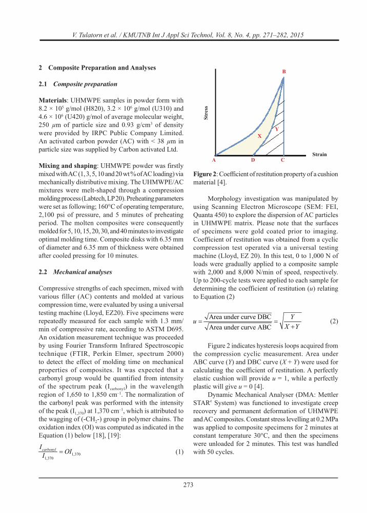
Morphology investigation was manipulated by using Scanning Electron Microscope (SEM: FEI, Quanta 450) to explore the dispersion of AC particles in UHMWPE matrix. Please note that the surfaces of specimens were gold coated prior to imaging. Coefficient of restitution was obtained from a cyclic compression test operated via a universal testing machine (Lloyd, EZ 20). In this test, 0 to 1,000 N of loads were gradually applied to a composite sample with 2,000 and 8,000 N/min of speed, respectively. Up to 200-cycle tests were applied to each sample for determining the coefficient of restitution (u) relating to Equation (2)
(2)
Figure 2 indicates hysteresis loops acquired from the compression cyclic measurement. Area under ABC curve (Y) and DBC curve (X + Y) were used for calculating the coefficient of restitution. A perfectly elastic cushion will provide u = 1, while a perfectly plastic will give u = 0 [4].
Dynamic Mechanical Analyser (DMA: Mettler STARe System) was functioned to investigate creep recovery and permanent deformation of UHMWPE and AC composites. Constant stress levelling at 0.2 MPa was applied to composite specimens for 2 minutes at constant temperature 30°C, and then the specimens were unloaded for 2 minutes. This test was handled with 50 cycles.
Figure 2: Coefficient of restitution property of a cushion material [4].
B
XY
A D C
Stre
ss
Strain
274
V. Tulatorn et al. / KMUTNB Int J Appl Sci Technol, Vol. 8, No. 4, pp. 271–282, 2015
2.3 Thermal analysis
Differential Scanning Calorimeter (DSC: TA Instruments, 2910) was used for a melting point characterization and the percent crystallinity of UHMWPE. Samples were heated from 30 to 200°C at a rate of 10°C/min. Melting temperature was taken at the peak of an endotherm. The degree of crystallinity (Xc) was calculated as follows [20]:
(3)
where;∆Hisheatoffusion 293 J/g is the melting enthalpy of polyethylene containing 100% of crystallinity
3 Results and Discussion
3.1 Compression strength
The impact of molecular weight on the deformation of UHMWPE can be probed with experiments as shown in Table 1. The results have been examined by comparing the compressive strength and tangent modulus to variations in molecular weight.
Table 1: Compressive strength at 80% deformation and tangent modulus of UHMWPE
UHMWPE Mw (×106) (mol/g)
Compressive strength (N/mm2)
Tangent modulus (N/m2)
H820 0.82 29.77 ± 1.71 1511.00 ± 40.06U320 3.20 34.00 ± 3.41 1575.53 ± 75.02U420 4.60 37.52 ± 3.05 1710.81 ± 74.77
Compressive strength at 80% deformation of UHMWPE increased as the molecular weight of the UHMWPE is greater. It can be explained that each chain of UHMWPE interacts each other by Van der Waals intermolecular forces. UHMWPE chains contain so many Van der Waals interactions that the total intermolecular strength is high. Since the molecular chains are very long, large overlaps between the molecules can occur. This overlapping enhances a capability to transfer large compressive force from molecule to molecule [21]. The UHMWPE holding higher molecular weight did not provide, however,
the dramatic increase in the compressive strength. The mechanical strength of polyethylene usually increases as the molecular weight of the polymer increases up to a certain molecular weight limit [22]. If the weight is higher than that restricted molecular weight, the mechanical strength tends towards to a constant value. The molecular weight around 60,000 g/mol is adequate to accomplish a strength surpassing 95% of the theoretical maximum at countless molecular weight. In terms of tangent modulus, the modulus indicates UHMWPE resistance to being deformed elastically if a force is applied to the UHMWPE. Longer chains afforded higher tangent modulus. The long chains can efficiently entangle with other chains, and then the entanglement can impede the movement of chains. This causes a too high elastic modulus. Based on the results, U420 was selected for composite preparation, because it gave the highest compressive strength at 80% deformation and tangent modulus.
UHMWPE is a thermal insulator which has thermal conductivity approximately 0.16–0.25 W/mK [23], and this insulating property may cause non-uniform melting during a compression process [11]. Therefore, optimal molding time should be observed by studying the effect of molding time on the compressive strength. Optimal time for compression molding was 40 minutes, whereas an optimal time spending for the composite preparation was 20 minutes. It could describe that introducing AC into the UHMWPE improved processability of the matrix. The enhancement in processability occurred because of the intrinsic thermal conductivity of pure carbon filler (nearby 600 W/mK) [24]. Accordingly, the thermal conductivity and capacity of UHMWPE/AC composites may be higher than those of neat UHMWPE.
Figure 3 presents the compressive stress at 80% deformation and tangent modulus of a composite (1%AC/ UHMWPE) as a function of the compression molding time. Result data illustrate that the tangent modulus and the compressive strength at 80% deformation of 1%AC/UHMWPE increased with extending time for hot pressing until 20 minutes. Those values of 1%AC/ UHMWPE reduced for longer time than 20 minutes, since the composite degraded. The results describe that the molding process needed a certain time for heat diffusing into the whole polymer matrix. The appropriate diffusion will produce a homogenous specimen providing high compressive strength which

275
V. Tulatorn et al. / KMUTNB Int J Appl Sci Technol, Vol. 8, No. 4, pp. 271–282, 2015
is the necessity for a pile cushion application. Hence, the compression time at 20 minutes was spent for the composite shaping process.
UHMWPE degrades during a plastic processing by compression molding or screw extrusion, principally because of the low mobility of the polymeric chains in UHMWPE. Macroradicals, which are produced from thermal decomposition of hydroperoxides [25], can be simply found in the bulk of neat UHMWPE.
Table 2: Oxidation index of 1%AC/UHMWPE at different compression time.
Materials Molding time (minutes) Icarbonyl I1,370 OI
UHMWPE 40 0.35 0.70 0.501%AC/UHMWPE 5 0.10 0.77 0.131%AC/UHMWPE 10 0.05 0.26 0.191%AC/UHMWPE 15 0.16 0.32 0.501%AC/UHMWPE 20 0.24 0.78 0.311%AC/UHMWPE 30 0.31 0.10 3.10
The macroradicals, in existence of oxygen, react freely donating hydroperoxyl radicals. Please note that oxygen is typically present during UHMWPE processing. Products created from the thermal oxidation can be ketones, alcohols, ethers, or carboxylic acid. Consequently, a carbonyl group, a part of those functional groups, is monitored for determining an oxidation index. The oxidation index is, therefore, important parameter to observe the UHMWPE
degradation which is basically concerned for the fabrication of a cushion pad. FTIR spectra were collected from each composite prepared by different molding time. The analysis from FTIR indicated that the intensity of peak at 1,370 cm–1 and carbonyl peak of 1%AC/UHMWPE was shown in table 2. To determine the oxidation index, the spectra were analyzed at each institution using Equation (1). The carbonyl region was quantified based on peak in the region of 1,650 to 1,850 cm–1. Normalization was calculated with the intensity of the peak at 1,370 cm–1 of wavelength. A group of conformationally sensitive, crystalline bands in polyethylene are interpreted from 1,370 cm–1 vibrations. The vibrations are also attributed to the wagging and twisting of (-CH2-) groups of the UHMWPE chains [18], [19]. The oxidation index of 1%AC/UHMWPE compression molded for 30 minutes was 3.10. It means that longer operating time than 20 minutes influences the degradation. The compressing time shorter than 15 minutes gave low oxidation index. It resulted from imperfect melting. The extremely high molecular weight of UHMWPE influences its melt viscosity, consequently; the material must be consolidated using controlled operating parameters for having complete melting. The fundamental relates to the compression molding of UHMWPE where the consolidation of materials is a direct result of heat, pressure, and heating time. Those parameters allow conformation change within the intergranular boundaries and reptation [11], [26].
Therefore, the impact of compression molding time on melting temperature was studied. Figure 4 shows the DSC thermograms scan of the UHMWPE prepared by compression molding. The melting temperature (Tm) of UHMWPE powder was closely 145°C, agreeing with earlier publications [26], [27], while processed UHMWPE shaped via compression molding showed 136°C of Tm. It may be because neat UHMWPE contains a thick lamella in a crystalline structure. Oppositely, the crystalline of the UHMWPE, which is passed polymer processing, will be changed by melting and solidification processes. The recrystallization of neat UHMWPE during a cooling step makes lamella structure thinner. Accordingly, the meting point of the compressed UHMWPE and composites shifted to 136°C. In other words, the meting point depends on the lamellar thickness according to The Gibbs-Thompson equation [28].
Figure 3: Compressive strength at 80% deformation and tangent modulus of 1%AC/UHMWPE (U420) at various time for compression molding.
5 10 15 20 25 3020
30
40
50
60
70
Compressive strength Secant modulus
Compression time (min)
mm/
N( htgnerts evisserpmo
C2 )
0
200
400
600
800
1000
1200
1400
1600
1800
2000
Tang
ent m
odul
us (N
/mm
2 )

276
V. Tulatorn et al. / KMUTNB Int J Appl Sci Technol, Vol. 8, No. 4, pp. 271–282, 2015
Tm values of most UHMWPE/AC composites are similar to the value of compressed UHMWPE. The interesting peaks were presented by 1%AC/UHMWPE compressed for 5 minutes. Its melting during DSC began at near 136°C and appeared as a 136°C was the main melting peak, and the peak was followed by a smaller at around 145°C. Low molecular mass macromolecules in the boundary of an UHMWPE specimen was initially melted. The peak from the main melting process corresponds to the main constitutive oriented orthorhombic crystals of the compressed specimen [26]. Masoomi et al. reported the interesting discussion about the double melting peaks as follows. The smaller peak may be due to the melting of hexagonal crystals that are transformed from the orthorhombic phase [26]. The existing of double endothermic peaks may relate to the introduction of AC into UHMWPE. The added AC can create the confinement of polymer chains with AC forming an interconnected structure, and then UHMWPE chains hardly moved and recoiled. That would affect to chain alignment and crystallization at a step of solidification. UHMWPE needs longer heating time to increase kinetic energy which forces UHMWPE chains to move and alignment uniformly. Single melting peaks were subsequently detected from UHMWPE specimens molded longer than 5 minutes.
In Figure 5, compression strength was plotted versus the AC concentration for UHMWPE/AC composites. Ideally if the reinforcing AC interacted strongly to a polymer matrix the compression strength
and the tangent modulus of composites are going to be higher. Nevertheless, it is obviously not the case here. The strength and modulus of UHMWPE/AC composites, increased meaningfully when introducing AC into UHMWPE. It can be clarified that the AC particles diminish the mobility of UHMWPE chains, and then the resistance of elastic deformity increases. The AC also plays an important role in stress transfer ability from matrix to AC clusters.
If adding AC into the matrix with the AC content was higher than 10 wt%, the strength and modulus of a composite decreased dramatically. The reduction problems usually associates with poor wetting and adhesion between matrix and filler particles [29].
The reduction of the strength is due to the agglomeration of AC. This idea can be confirmed by the SEM micrographs (Figure 6). Figure 6f depicts AC agglomerations and poor interfacial adhesion between filler and UHMWPE surfaces. The clusters act as a stress riser, which is a location in a polymer matrix where stress is concentrated.
Table 3: Degree of crystallinity of UHMWPE/AC composites with various AC loading
Material Xc (%)Compressed UHMWPE 53.58
5%AC/UHMWPE 45.3210%AC/UHMWPE 43.5520%AC/UHMWPE 39.39
Figure 5: Compressive strength at 80% deformation and tangent modulus of UHMWPE (U420) with various AC concentration.
0 4 8 12 16 2020
30
40
50
60
70
Compressive strength Secant modulus
mm/
N( htgnerts evisserpmo
C2 )
0
200
400
600
800
1000
1200
1400
1600
1800
2000
Tan
gent
mod
ulus
(N/m
m2 )
Amount of AC (wt %)
Figure 4: DSC thermograms of UHMWPE and 1%AC/ UHMWPE at different molding time.
40 80 120 160 200
Compressed UHMWPE
Uncompressed UHMWPE
1%AC/UHMWPE-10 min
1%AC/UHMWPE-20 min
)W
m( wolf taeH
Temperature (°C)
1%AC/UHMWPE-5 min

277
V. Tulatorn et al. / KMUTNB Int J Appl Sci Technol, Vol. 8, No. 4, pp. 271–282, 2015
Table 3 indicates that AC particles did not act as nucleating agent as anticipated. The degree of crystallinity of UHMWPE decreased if AC was incorporated into UHMWPE. Higher amount of AC containing in UHMWPE gave a lower degree of crystallinity. That may be due to AC clusters insert between polymer chains, and then amorphous state is increased.
3.2 Cyclic compression test
A cyclic compression test is usually performed for studying material fatigue that refers to the material degradation and accumulated damage [15]. Polymers also subjected to the compression cyclic loading experience a hysteresis and softening phenomena when a critical cyclic strain is attained [30]. This work studied the cyclic strain behavior to determine the coefficient of restitution. The results of cyclic
compression tested with loading of 0–1,000 N and unloading for 100 cycle at speed of 2,000 N/min are illustrated in Figure 7. The results presented cycles comprised triangle patterns, and on cycle comprised of stretching the specimen to a specified compression at an equal compression rate till zero load. At compression rate of 2,000 N/min, hysteresis loops at cycle No. 10 of UHMWPE and a composite were broader than the ones at cycle No. 100, as shown in Figure 7. As with constitutive theory, a permanent deformity in microstructure leads to cyclic constancy in the beginning of compressive force is applied. Afterwards, a cyclic steady state with continuous cycling but upon unloading, some microstructural and morphological deformities are recovered [31].
A direct comparison between hysteresis loops of neat UHMWPE and 3%AC/UHMWPE indicates that the composite gave lower deformation and more reversibility than the UHMWPE did. As seen from the results, the coefficient of restitution at cycle No.100 of UHMWPE was 0.59, whereas; the coefficient of the composite was 0.65. The perpetual deformation of UHMWPE and 3%AC/UHMWPE were 1.55 mm and 1.21 mm, respectively. The AC particles and clusters enhance mechanical strength of UHMWPE by distributing the applied force to all bulk. It implies that the composites can provide better reversibility after it was compressed or impacted, and better transmission driving energy to the pile than the UHMWPE can do. In terms of the effect of compressive rate on material load-strain behavior, both materials tested at higher
Figure 6: SEM of surface of (a) UHMWPE (b) 1%AC/ UHMWPE (c) 3%AC/UHMWPE (d) 5%AC/ UHMWPE (e) 10%AC/UHMWPE and (f) 20%AC/ UHMWPE.
Figure 7: Deformation in neat UHMWPE (U420) and 3%AC/ UHMWPE’s load - strain behavior due to compression cyclic loading at 2,000 N/min of compressive rate.
0.5 1.0 1.5 2.0 2.5
0
200
400
600
800
1000
1200
1400
U420 at cycle No.10 U420 at cycle No.100 3%AC/UHMWPE at cycle No.10 3%AC/UHMWPE at cycle No.100
Strain (mm)
)N( daoL

278
V. Tulatorn et al. / KMUTNB Int J Appl Sci Technol, Vol. 8, No. 4, pp. 271–282, 2015
compressive rate gave greater coefficients of restitution. Figure 8 shows hysteresis loops at the same cycle (cycle No. 100) from the experiments running with 2,000 N/min and 8,000 N/min of compressive rates. That can be investigated that permanent deformation at speed of 2,000 and 8,000 N/min for neat UHMWPE were 1.57 and 1.24 mm, respectively.
The results from 3%AC/UHMWPE delivered the same tendency as the UHMWPE. The permanent deformation at 2,000 N/min and 8,000 N/min of compressive speeds for 3%AC/UHMWPE equalled 1.22 and 1.17 mm respectively. Tests running with higher compressive rate provided narrower hysteresis loops which gave a higher value for the coefficient of restitution. If the cycle No. 20 to 100 were considered, the coefficient of restitution of the 3%AC/UHMWPE composite increased from the range of 0.55–0.67 to the range of 0.65–0.72.
The rational explanation is about the required time for polymer chain orientation. When the same quantity of compressive force is applied to materials fast, the polymer chains do not have enough time for moving and rearranging. The elastic deformation that compared to the plastic deformation will prominently respond. The coefficient of restitution of composites conducted at 2,000 N/min of speed showed higher performance than the value of neat UHMWPE. Although, the coefficients of restitution from speed of 8,000 N/min did not show the significant dissimilarity (Figure 9(a) and 9(b)). The Figure 9 also displays the impact of compressing cycle number. The coefficient
of all materials elevated with increasing the cycle number. The 3%AC/ UHMWPE exhibited the most elasticity of all samples, since composites containing higher AC loading than 3 wt% became a brittle material.
Cycles of 200 were chosen to provide an order of magnitude difference between the cycles to help ensure statistical significance of any morphological differences noted (Figure 10). Figure 10 illustrates the 200-hysteresis cycles of 10%AC/UHMWPE and medium density fibreboard (MDF). The cycles show that the residual strain of 10%AC/UHMWPE is higher than the residual strain of MDF. The coefficients of the restitution of medium density fibreboard and 10%AC/UHMWPE improved with an increase in compression cycles (Figure 11).
Figure 8: Cyclic compression testing at cycle No. 100 of UHMWPE (U420) and 3%AC/UHMWPE at speed of 2,000 N/min and 8,000 N/min.
Figure 9: The effect of compressive rates ((a) 2000 N/min (b) 8000 N/min) on materials’ coefficient of restitution.
1.0 1.1 1.2 1.3 1.4 1.5 1.6 1.7 1.8 1.9 2.0
0
200
400
600
800
1000
1200
1400
U420 at speed of 2,000 N/mm U420 at speed of 8,000 N/mm 3%AC/UHMWPE at speed of 2,000 N/mm 3%AC/UHMWPE at speed of 8,000 N/mm
Strain (mm)
)N( daoL
0 20 40 60 80 1000.0
0.1
0.2
0.3
0.4
0.5
0.6
0.7
0.8
noitutitser tneiciffeoC
Cycle No.
U420 1%AC/UHMWPE 3%AC/UHMWPE 5%AC/UHMWPE 10%AC/UHMWPE 20%AC/UHMWPE
(a)
0 20 40 60 80 1000.1
0.2
0.3
0.4
0.5
0.6
0.7
0.8
noitutitser tneiciffeoC
Cycle No.
U420 1%AC/UHMWPE 3%AC/UHMWPE 5%AC/UHMWPE 10%AC/UHMWPE 20%AC/UHMWPE
(b)

279
V. Tulatorn et al. / KMUTNB Int J Appl Sci Technol, Vol. 8, No. 4, pp. 271–282, 2015
The coefficients of the fibreboard were higher than the coefficients of the composites. At cycle No. 200, the coefficients of restitution of the medium density fibreboard decreased from 0.92 to 0.88, although the coefficients of restitution of 10%AC/UHMWPE was constant (u = 0.83). The permanent deformation of the fibreboard (1.21 mm) was also lower than the values of the composite (1.28 mm). The coefficients of restitution of both materials close to 1.00 which exhibits low energy dissipation, good energy transference to driving pile, and good recovery.
3.3 Creep test
Creep graphs, in Figure 12, display two main different zones of behavior for the creep strain rate as a function of time. The creep strain rate drastically increased, in the initial primary creep regime, when stress was applied. In the secondary regime, the creep strain is almost constant over time as long as the stress was maintained.
After the removal of the stress for 2 minutes, the elastic strain quickly recovered. The portion of the creep strain was recovered slowly with time, and the unrecovered strain was remained. That is because a short duration for the recovering period was provided representing permanent deformation, as shown in Figure 12. Figure 13 presents the incorporating AC with UHMWPE decreased the percentage of creep strain. An escalation in AC concentration affected the reduction of the percentage of creep. The results have the tendency as a previous publication stating that the creep rate is markedly decreased by the nanofillers, especially at the high times [17].
Figure 10: Cyclic load-strain curves for (a) medium density fibreboard and (b) 10%AC/UHMWPE under 8,000 N/min of compression rate, 200 cycles, and 0–1,000 N of load.
0.2 0.4 0.6 0.8 1.0 1.2 1.4 1.6 1.8
0
200
400
600
800
1000
)N( daoL
Strain (mm)
(a)
0.4 0.6 0.8 1.0 1.2 1.4 1.6 1.8 2.0
0
200
400
600
800
1000
)N( daoL
Strain (mm)
(b)
0 50 100 150 2000.4
0.6
0.8
1.0
noitutitser fo tneiciffeoC
Cycle No.
medium density fibreboard 10%AC/UHMWPE
Figure 11: Coefficient of restitution of wood and 10% AC/UHMWPE, 0–1000 N of loading at speed of 8000 N/min.
11850 11900 11950 12000 12050 12100 12150-50
0
50
100
150
200
250 (b)
)mµ( niartS
Time (s)
UHMWPE 1%AC/UHMWPE 3%AC/UHMWPE 10%AC/UHMWPE
Figure 12: The creep strain curve of UHMWPE and UHMWPE composite at 50 creep-recovery cycles.

280
V. Tulatorn et al. / KMUTNB Int J Appl Sci Technol, Vol. 8, No. 4, pp. 271–282, 2015
This issue can be rationally clarified that AC particles cannot be deformed by the force, and then higher loading of AC causes the decrease in overall deformity of composites. On the other hand, the AC particles reinforce UHMWPE by stress transferring to the UHMWPE matrix, thus; UHMWPE composites can have superior creep behavior. Figure 14 presents permanent deformation of all materials gradually increased with an increase in creep-recover cycles. The magnitude of deformation was not significantly changed, since the force (0.2 MPa) applied to the samples may be less than the yield stress of the composites’ deformation.
4 Conclusions
In the present work, a long-term experimental investigation was performed to probe the mechanical responses of neat UHMWPE and UHMWPE/AC composites under the cyclic compressive loading conditions for the preliminary investigation relating to requirements of the pile cushions.
The compressive strength at 80% deformation and tangent modulus of UHMWPE increased with increasing molecular weight of UHMWPE. They also depended on time for hot pressed and quantity of AC. 10% AC/UHMWPE has the highest compressive strength and tangent modulus. The coefficient of restitution of samples tested at compression speed of 8,000 N/min were conducted under compression rate of 2,000 N/min. The coefficient of restitution of composites implies that the materials can transfer driving energy to a pile, and have good recovery feature. However, the result indicates that the composites do not dissipate energy well. Permanent deformation determined from a creep test indicates that the UHMWPE composites increased with increasing the cycle number of compression as same as cyclic compression testing. Addition of AC can reduced compression period that is an advantage for commercial production. The necessary performance targets for the pile cushion application was not yet achieved for these composites, and the mechanical performance of composites is inferior to the performance of MDF. Contrarily, the composite do show promise for future opportunities as materials for a pile cushion pad in long term.
Acknowledgments
It is an honour for Integrated Nano Research Centre, KMUTNB to acknowledge Siam Engineering Group Company for giving financial support to operate this research.
References
[1] G. L. Henderson, Behavior of fiber-reinforced polymer composite piles under vertical loads, USA: Turner-Fairbank Highway Research Center, 2006, pp. 1–100.
[2] E. Guades, T. Aravinthan, M. Islam, and A. Manalo,
Figure 13: Percentage of creep strain of the composites loaded with constant stress of 0.2 MPa for 2 min and unloaded for 2 min at cycle No. 10, 20, 30, 40 and 50 and temperature of 30ºC.
Figure 14: Percentage of permanent deformation of the composites were loaded with constant stress of 0.2 MPa for 2 min and unloaded for 2 min at cycle No. 10, 20, 30, 40 and 50 and temperature of 30ºC.
10 20 30 40 500.000
0.001
0.002
0.003
0.004
0.005
)%( niarts peerC
Cycle No.
U420 1%AC/UHMWPE 3%AC/UHMWPE 10%AC/UHMWPE
10 20 30 40 500
10
20
30
40
50
)01X( noitamrofed tnena
mreP-6 (%
)
Cycle No.
U420 1%AC/UHMWPE 3%AC/UHMWPE 10%AC/UHMWPE

281
V. Tulatorn et al. / KMUTNB Int J Appl Sci Technol, Vol. 8, No. 4, pp. 271–282, 2015
“A review on the driving performance of FRP composite piles,” Compos. Struct., vol. 94, pp. 1932–1942, 2012.
[3] S. L. Borg, “Polymeric piles: a cost-effective and environmentally friendly practice,” Pilediver, winter, vol. 1, pp. 14–15, 2004.
[4] T. J. Hirsch and T.C. Edwards, “Impact load-deformation properties of pile cushioning materials,” Research Project Number 2-5-62-33, Texas transportation institute, USA, 1966.
[5] L. L. Lowery, “Pile driving analysis state of the art,” Research study Number 2-5-62-33, The Texas highway department, 1969.
[6] S. Whitty, “Pile cushions: a make or break proposition,” Pilediver, winter, vol. 1, pp. 14–16, 2005.
[7] G. Sui, “Structure, mechanical properties and friction behavior of UHMWPE/HDPE/ carbon nanofibers,” Mater. Chem. Phys., vol. 115, pp. 404–412, 2009.
[8] L. A. Pruitt, “Deformation, yielding, fracture and fatigue behavior of conventional and highly cross-linked ultra high molecular weight polyethylene,” Biomaterials, vol. 26, pp. 905–915, 2005.
[9] J. Fu, “High temperature melted, radiation cross-linked, vitamin E stabilized oxidation resistant UHMWPE with low wear and high impact strength,” Polymer, vol. 54, pp. 199–209, Nov. 2013.
[10] C. Z. Liu, “Statistical wear analysis of PA-6/UHMWPE alloy, UHMWPE and PA-6,” Wear, vol. 249, pp. 31–36, 2001.
[11] M. Allen, UHMWPE processing: techniques and problems, United Kingdom: Perplas Medical, 2005, pp. 1–13.
[12] D. I. Chukov, “Investigation of structure, mechanical and tribological properties of short carbon fiber reinforced UHMWPE-matrix composites,” Compos. Part B, vol. 76, pp. 79–88, 2015.
[13] B. Ledesma, “Cyclic adsorption/thermal regeneration of activated carbons,” J. Anal. Appl. Pyrol., vol. 106, pp. 112–117, 2014.
[14] J. P. Attwood, N. A. Fleck, H. N. G. Wadley, and V.S. Deshpande, “The compressive response of ultra-high molecular weight polyethylene fibres and composites,” Int. J. Solids Struct., vol. 71, no. 1, pp. 141–155, 2015.
[15] R. W. Meyer and L. A. Pruitt, “The effect of cyclic true strain on the morphology, structure, and relaxation behavior of ultra-high molecular weight polyethylene,” Polymer, vol. 42, pp. 5293– 5306, 2001.
[16] A. B. Chai, A. Andriyana, E. Verron, and M. R. Johan, “Mechanical characteristics of swollen elastomers under cyclic loading,” Materials and Design, vol. 44, pp. 566–572, 2013.
[17] S. Siengchin and R. Haag, “A Review of Creep Resistance of Nano - Scale Reinforcing Thermoplastics,” AIJSTPME, vol. 2, no. 4, pp. 15– 20, 2009.
[18] S. M. Kurtz, “Interlaboratory reproducibility of standard accelerated aging methods for oxidation of UHMWPE,” Biomaterials, vol. 22, pp. 1731– 1737, 2000.
[19] M. Sloufa, T. Vackova, M. Nevoralova, and D. Pokorny “Micromechanical properties of one-step and sequentially crosslinked UHMWPEs for total joint replacements,” Polym. Test., vol. 41, pp. 191–197, 2015.
[20] M. E. Sotomayor, “Thermal and mechanical characterization of injection moulded high density polyethylene/paraffin wax blends as phase change materials,” Renew. Energ., vol. 68, pp. 140–145, 2014.
[21] L. M. Nicholson, K. S. Whitley, T. S. Gates, and J. A. Hinkley, “How molecular structure affects mechanical properties of an advanced polymer,” National Research Council Resident Research Associate, USA: NASA Langley Research Center, pp. 1–15, 2000.
[22] J. Wang and K. J. Smith Jr., “The breaking strength of ultra-high molecular weight polyethylene fibers,” Polymer, vol. 40, pp. 7261– 7274, 1999.
[23] K. Enomoto, S. Fujiwara, T. Yasuhara, H. Murakami, J. Teraki, and N. Ohtake, “Filler orientation on thermal conductivity of polypropylene matrix carbon nanofiber composites,” Jpn. J. Appl. Phys., vol. 40, pp. L888 – L891, 2005.
[24] C. Du, P. Ming, M. Hou, J. Fu, Q. Shen, D. Liang, Y. Fu, X. Luo, Z. Shao, and B. Yi, “Preparation and Properties of Thin Epoxy/Compressed Expanded Graphite Composite Bipolar Plates for Proton Exchange Membrane Fuel Cells,” J. Power Sources, vol. 1950, pp. 794–800, 2010.

282
V. Tulatorn et al. / KMUTNB Int J Appl Sci Technol, Vol. 8, No. 4, pp. 271–282, 2015
[25] S. M. Kurtz, The UHMWPE handbook: Ultra-high molecular weight polyethylene in total joint replacement, London: Elserier Inc., 2004.
[26] M. Masoomi, S. R. Ghaffarian , and N. Mohammadi, “The effect of processing conditions and matrix type on the interface of polyethylenefibre/ polyethylene-matrix composites,” Iran. Polym. J., vol. 13, no. 5, pp. 381–387, 2004.
[27] J.-T. Yeh, S.-C. Lin, C.-W. Tu, K.-H. Hsie, and F.-C. Chang, “Investigation of the drawing mechanism of UHMWPE fibers,” J. Mater. Sci., vol. 43, pp. 4892–4900, 2008.
[28] G. W. H. Hohne, “Another approach to the Gibbs- Thomson equation and the melting point of polymers and oligomers,” Polymer, vol. 43,
pp. 4689–4698, 2002.[29] J. Karger-Kocsis and S. Siengchin, “Single-
Polymer Composites: Concepts, Realization and Outlook: Review,” KMUTNB Int J Appl Sci Technol, vol.7, no.1, pp. 1–9, 2014.
[30] J. S. Bergstrom, S. M. Kurtz, C. M. Rimnac, and A. A. Edidin, “Constitutive modeling of ultra-high molecular weight polyethylene under large deformation and cyclic loading conditions,” Biomaterials, vol. 23, pp. 2329–2343, 2002.
[31] D. J. Krzypow and C. M. Rimnac, “Cyclic steady state stress-strain behavior of UHMW polyethylene,” Biomaterials, vol. 21, pp. 2081–2087, 2000.