Mechanical anchoring Anchor Fastening Technology Manual ... · PDF fileAnchor Fastening...
21
Mechanical anchoring systems 01 / 2016 76 Anchor Fastening Technology Manual HSC-A HSC-AR HSC-I HSC-IR Undercut anchor
Transcript of Mechanical anchoring Anchor Fastening Technology Manual ... · PDF fileAnchor Fastening...

Mechanical anchoring systems
01 / 2016
76
Anchor Fastening
Technology Manual
HSC-A HSC-AR HSC-I HSC-IR Undercut anchor

HSC-A Safety anchor
07 / 2012
77
HSC-A Safety anchor
Anchor version Benefits
Bolt version
HSC-A Carbon Steel version
HSC-AR Stainless steel version
- the perfect solution for small edge and space distance
- suitable for thin concrete blocks due to low embedment depth
- suitable for cracked concrete
- self-cutting undercut anchor
- available as bolt version for through applications
- stainless steel available for external applications
Concrete Tensile zone
Shock Small edge
distance and spacing
Fire resistance
Corrosion resistance
European Technical Approval
CE conformity
PROFIS Anchor design
software
Approvals / certificates
Description Authority / Laboratory No. / date of issue
European technical approval a)
CSTB, Paris ETA-02/0027 / 2012-09-20
Shockproof fastenings in civil defence installations
Federal Office for Cicil Protection, Bern
BZS D 06-601 / 2006-07-10
Fire test report IBMB, Braunschweig UB 3177/1722-1 / 2006-06-28
Assessment report (fire) warringtonfire WF 327804/A / 2013-07-10
a) All data given in this section according ETA-02/0027 issue 2012-09-20.
Basic loading data
All data in this section applies to For details see Simplified design method - Correct setting (See setting instruction) - No edge distance and spacing influence - Concrete as specified in the table - Steel failure - Minimum base material thickness - Concrete C 20/25, fck,cube = 25 N/mm²

HSC-A Safety anchor
01 / 2016
78
Mean ultimate resistance
Non-cracked concrete Cracked concrete
Anchor size M8x40 M10x40 M8x50 M12x60 M8x40 M10x40 M8x50 M12x60
Tensile NRu,m
HSC-A
HSC-AR [kN] 16,6 16,6 23,3 30,6 13,3 13,3 18,6 24,5
Shear VRu,m
HSC-A [kN] 19,0 30,2 19,0 43,8 19,0 30,2 19,0 43,8
HSC-AR [kN] 16,6 26,4 16,6 38,4 16,6 26,4 16,6 38,4
Characteristic resistance
Non-cracked concrete Cracked concrete
Anchor size M8x40 M10x40 M8x50 M12x60 M8x40 M10x40 M8x50 M12x60
Tensile NRk
HSC-A [kN] 12,8 12,8 17,8 23,4 9,1 9,1 12,7 16,7
HSC-AR [kN] 12,8 12,8 17,8 23,4 9,1 9,1 12,7 16,7
Shear VRk
HSC-A [kN] 14,6 23,2 14,6 33,7 14,6 18,2 14,6 33,5
HSC-AR [kN] 12,8 20,3 12,8 29,5 12,8 18,2 12,8 29,5
Design resistance
Non-cracked concrete Cracked concrete
Anchor size M8x40 M10x40 M8x50 M12x60 M8x40 M10x40 M8x50 M12x60
Tensile NRd
HSC-A [kN] 8,5 8,5 11,9 15,6 6,1 6,1 8,5 11,2
HSC-AR [kN] 8,5 8,5 11,9 15,6 6,1 6,1 8,5 11,2
Shear VRd
HSC-A [kN] 11,7 17,0 11,7 27,0 11,7 12,1 11,7 22,3
HSC-AR [kN] 8,2 13,0 8,2 18,9 8,2 12,1 8,2 18,9
Recommended loads
Non-cracked concrete Cracked concrete
Anchor size M8x40 M10x40 M8x50 M12x60 M8x40 M10x40 M8x50 M12x60
Tensile Nrec a)
HSC-A [kN] 6,1 6,1 8,5 11,2 4,3 4,3 6,1 8,0
HSC-AR [kN] 6,1 6,1 8,5 11,2 4,3 4,3 6,1 8,0
Shear Vrec a)
HSC-A [kN] 8,3 12,1 8,3 19,3 8,3 8,7 8,3 15,9
HSC-AR [kN] 5,9 9,3 5,9 13,5 5,9 8,7 5,9 13,5
a) With overall partial safety factor for action = 1,4. The partial safety factors for action depend on the type of loading and shall be taken from national regulations.
HSC-A Safety anchor
07 / 2012
79
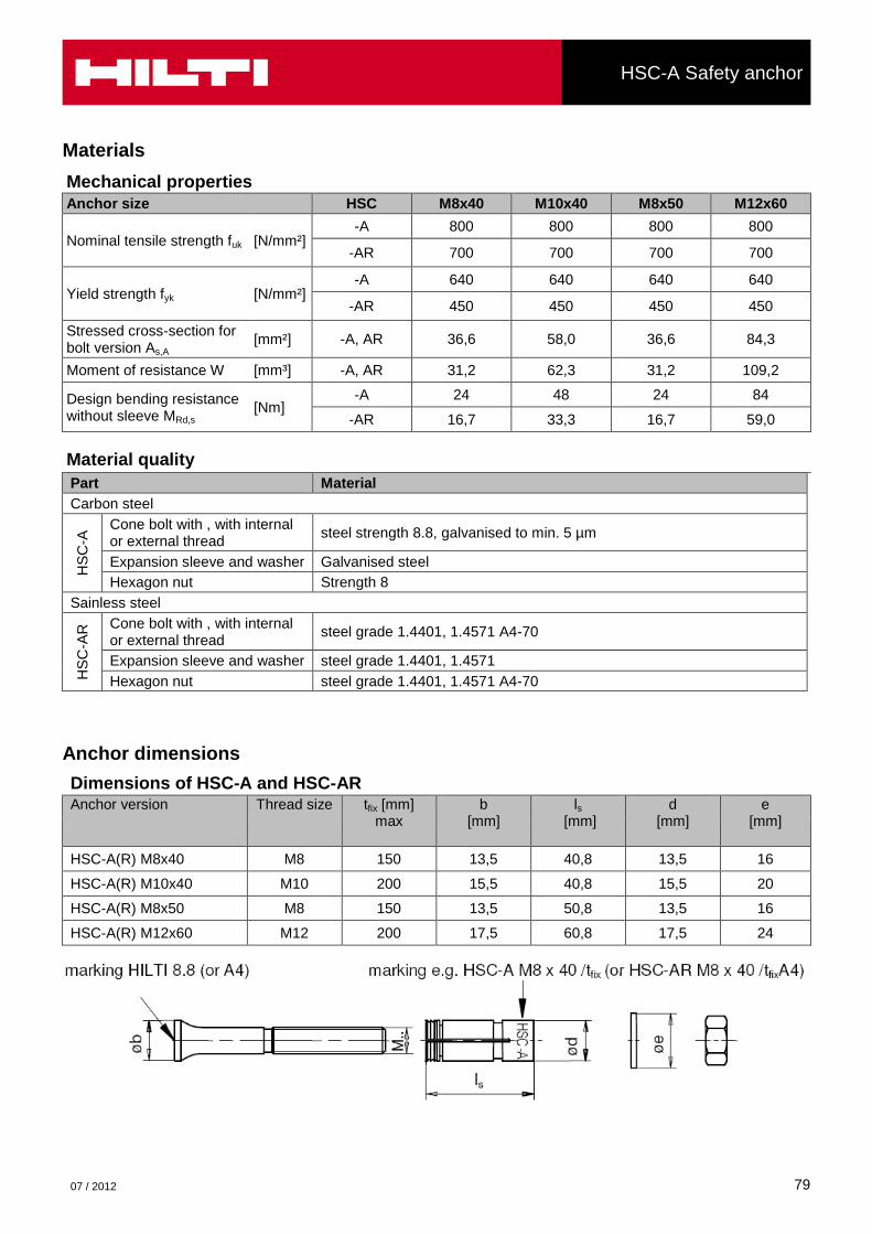
Materials
Mechanical properties
Anchor size HSC M8x40 M10x40 M8x50 M12x60
Nominal tensile strength fuk [N/mm²] -A 800 800 800 800
-AR 700 700 700 700
Yield strength fyk [N/mm²] -A 640 640 640 640
-AR 450 450 450 450
Stressed cross-section for bolt version As,A
[mm²] -A, AR 36,6 58,0 36,6 84,3
Moment of resistance W [mm³] -A, AR 31,2 62,3 31,2 109,2
Design bending resistance without sleeve MRd,s
[Nm] -A 24 48 24 84
-AR 16,7 33,3 16,7 59,0
Material quality
Part Material
Carbon steel
HS
C-A
Cone bolt with , with internal or external thread
steel strength 8.8, galvanised to min. 5 µm
Expansion sleeve and washer Galvanised steel
Hexagon nut Strength 8
Sainless steel
HS
C-A
R Cone bolt with , with internal
or external thread steel grade 1.4401, 1.4571 A4-70
Expansion sleeve and washer steel grade 1.4401, 1.4571
Hexagon nut steel grade 1.4401, 1.4571 A4-70
Anchor dimensions
Dimensions of HSC-A and HSC-AR Anchor version Thread size tfix [mm]
max b
[mm]
ls
[mm]
d [mm]
e [mm]
HSC-A(R) M8x40 M8 150 13,5 40,8 13,5 16
HSC-A(R) M10x40 M10 200 15,5 40,8 15,5 20
HSC-A(R) M8x50 M8 150 13,5 50,8 13,5 16
HSC-A(R) M12x60 M12 200 17,5 60,8 17,5 24
HSC-A Safety anchor
01 / 2016
80
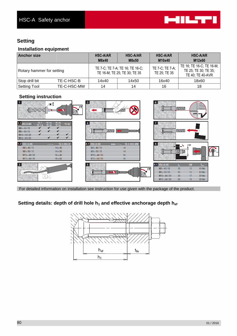
Setting
Installation equipment
Anchor size HSC-A/AR
M8x40
HSC-A/AR
M8x50
HSC-A/AR
M10x40
HSC-A/AR
M12x60
Rotary hammer for setting TE 7-C; TE 7-A; TE 16; TE 16-C;
TE 16-M; TE 25; TE 30; TE 35 TE 7-C; TE 7-A;
TE 25; TE 35
TE 16; TE 16-C; TE 16-M; TE 25; TE 30; TE 35;
TE 40; TE 40-AVR
Stop drill bit TE-C-HSC-B 14x40 14x50 16x40 18x60
Setting Tool TE-C-HSC-MW 14 14 16 18
Setting instruction
For detailed information on installation see instruction for use given with the package of the product.
Setting details: depth of drill hole h1 and effective anchorage depth hef

HSC-A Safety anchor
07 / 2012
81
Setting details HSC-A (R)
Anchor version M8x40 M10x40 M8x50 M12x60
Nominal diameter of drill bit do [mm] 14 16 14 18
Cutting diameter of drill bit dcut ≤ [mm] 14,5 16,5 14,5 18,5
Depth of drill hole h1 ≥ [mm] 46 46 56 68
Diameter of clearance hole in the fixture
df ≤ [mm] 9 12 10 30
Effective anchorage depth hef [mm] 40 40 50 60
Maximum fastening thickness tfix [mm] 15 20 15 20
Torque moment Tinst [Nm] 10 20 10 30
Width across SW [mm] 13 17 13 19
Base material thickness, anchor spacing and edge distance
Anchor size M8x40 M10x40 M8x50 M12x60
Minimum base material thickness
hmin [mm] 100 100 100 130
Minimum spacing smin [mm] 40 40 50 60
Minimum edge distance
cmin [mm] 40 40 50 60
Critical spacing for concrete cone failure
scr,N [mm] 120 120 150 180
Critical edge distance for concrete cone failure
ccr,N [mm] 60 60 75 90
Critical spacing for splitting failure
scr,sp [mm] 130 120 170 180
Critical edge distance for splitting failure
ccr,sp [mm] 65 60 85 90
For spacing (edge distance) smaller than critical spacing (critical edge distance) the design loads have to be reduced. Critical spacing and critical edge distance for splitting failure apply only for non-cracked concrete. For cracked concrete only the critical spacing and critical edge distance for concrete cone failure are decisive.

HSC-A Safety anchor
01 / 2016
82
Simplified design method
Simplified version of the design method according ETAG 001, Annex C. Design resistance according data given in ETA-02/0027 issue 2012-09-20.
Influence of concrete strength Influence of edge distance Influence of spacing Valid for a group of two anchors. (The method may also be applied for anchor groups with more than two
anchors or more than one edge. The influencing factors must then be considered for each edge distance and spacing. The calculated design loads are then on the save side: They will be lower than the exact values according ETAG 001, Annex C. To avoid this, it is recommended to use the anchor design software PROFIS anchor)
The design method is based on the following simplification: No different loads are acting on individual anchors (no eccentricity)
The values are valid for one anchor. For more complex fastening applications please use the anchor design software PROFIS Anchor.
Tension loading
The design tensile resistance is the lower value of
- Steel resistance: NRd,s
- Concrete pull-out resistance: NRd,p = N0Rd,p fB
- Concrete cone resistance: NRd,c = N0Rd,c fB f1,N f2,N f3,N fre,N
- Concrete splitting resistance (only non-cracked concrete):
NRd,sp = N0Rd,c fB f1,sp f2,sp f3,sp f h,sp fre,N
Basic design tensile resistance
Design steel resistance NRd,s
Anchor size M8x40 M10x40 M8x50 M12x60
NRd,s HSC-A [kN] 19,5 30,9 19,5 44,9
HSC-AR [kN] 13,7 21,7 13,7 31,6
Design pull-out resistance NRd,p = N0Rd,p fB for HSC-A and HSC-AR
Non-cracked concrete Cracked concrete
Anchor size M8x40 M10x40 M8x50 M12x60 M8x40 M10x40 M8x50 M12x60
N0Rd,p [kN] No pull-out failure No pull-out failure
Design concrete cone resistance NRd,c = N0Rd,c fB f1,N f2,N f3,N fre,N
Design splitting resistance a) NRd,sp = N0Rd,c fB f1,sp f2,sp f3,sp f h,sp fre,N
Non-cracked concrete Cracked concrete
Anchor size M8x40 M10x40 M8x50 M12x60 M8x40 M10x40 M8x50 M12x60
N0Rd,c [kN] 8,5 8,5 11,9 15,6 6,1 6,1 8,5 11,2
a) Splitting resistance must only be considered for non-cracked concrete

HSC-A Safety anchor
07 / 2012
83
Influencing factors
Influence of concrete strength
Concrete strength designation (ENV 206)
C 20/25 C 25/30 C 30/37 C 35/45 C 40/50 C 45/55 C 50/60
fB = (fck,cube/25N/mm²)1/2
a)
1 1,1 1,22 1,34 1,41 1,48 1,55
a) fck,cube = concrete compressive strength, measured on cubes with 150 mm side length
Influence of edge distance a)
c/ccr,N 0,1 0,2 0,3 0,4 0,5 0,6 0,7 0,8 0,9 1
c/ccr,sp
f1,N = 0,7 + 0,3c/ccr,N ≤ 1 0,73 0,76 0,79 0,82 0,85 0,88 0,91 0,94 0,97 1
f1,sp = 0,7 + 0,3c/ccr,sp ≤ 1
f2,N = 0,5(1 + c/ccr,N) ≤ 1 0,55 0,60 0,65 0,70 0,75 0,80 0,85 0,90 0,95 1
f2,sp = 0,5(1 + c/ccr,sp) ≤ 1
a) The edge distance shall not be smaller than the minimum edge distance cmin given in the table with the setting details. These influencing factors must be considered for every edge distance.
Influence of anchor spacing a)
s/scr,N 0,1 0,2 0,3 0,4 0,5 0,6 0,7 0,8 0,9 1
s/scr,sp
f3,N = 0,5(1 + s/scr,N) ≤ 1 0,55 0,60 0,65 0,70 0,75 0,80 0,85 0,90 0,95 1
f3,sp = 0,5(1 + s/scr,sp) ≤ 1
a) The anchor spacing shall not be smaller than the minimum anchor spacing smin given in the table with the setting details. This influencing factor must be considered for every anchor spacing.
Influence of base material thickness
h/hef 2,0 2,2 2,4 2,6 2,8 3,0 3,2 3,4 3,6 ≥ 3,68
f h,sp = [h/(2hef)]2/3
1 1,07 1,13 1,19 1,25 1,31 1,37 1,42 1,48 1,5
Influence of reinforcement
Anchor size M8x40 M10x40 M8x50 M12x60
fre,N = 0,5 + hef/200mm ≤ 1 0,7 a)
0,7 a)
0,75 a)
0,8 a)
a) This factor applies only for dense reinforcement. If in the area of anchorage there is reinforcement with a spacing ≥ 150 mm (any diameter) or with a diameter ≤ 10 mm and a spacing ≥ 100 mm, then a factor fre,N = 1 may be applied.
HSC-A Safety anchor
01 / 2016
84
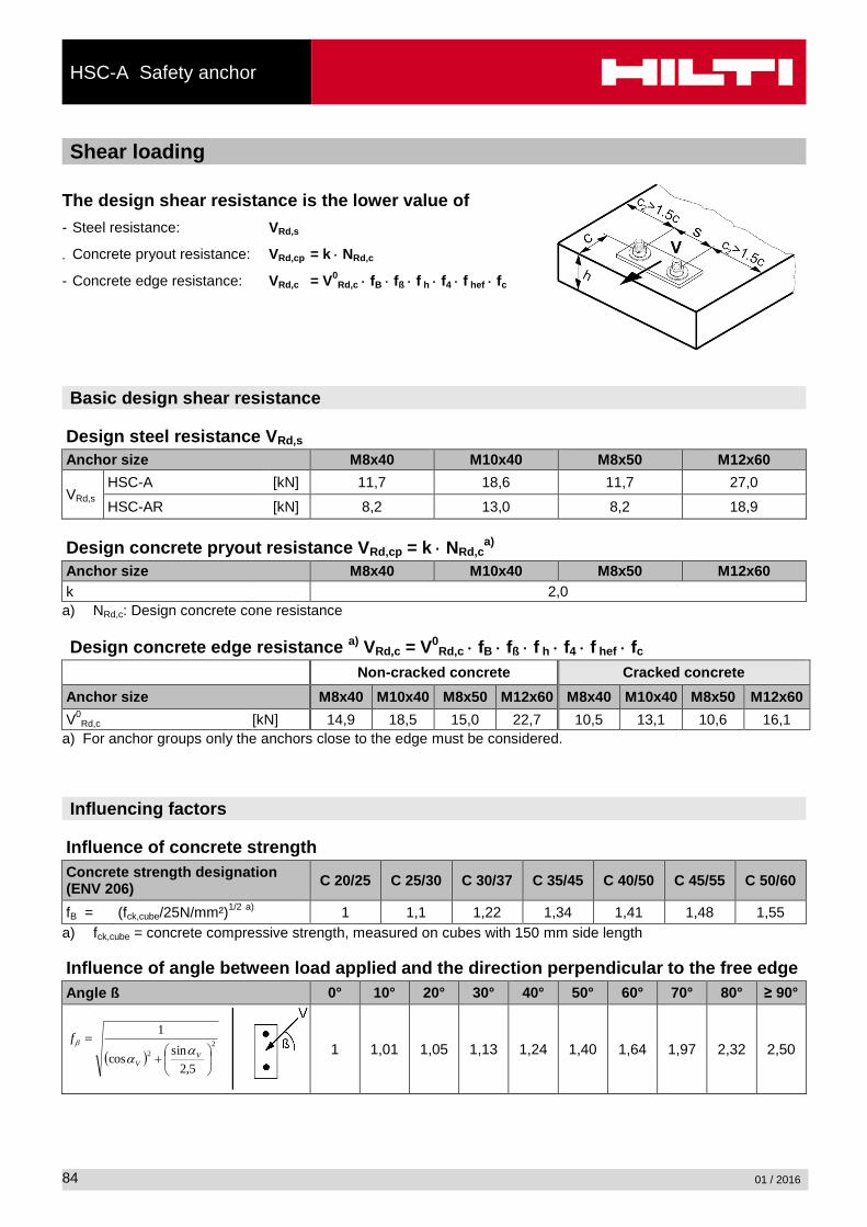
Shear loading
The design shear resistance is the lower value of
- Steel resistance: VRd,s
- Concrete pryout resistance: VRd,cp = k NRd,c
- Concrete edge resistance: VRd,c = V0Rd,c fB fß f h f4 f hef fc
Basic design shear resistance
Design steel resistance VRd,s
Anchor size M8x40 M10x40 M8x50 M12x60
VRd,s HSC-A [kN] 11,7 18,6 11,7 27,0
HSC-AR [kN] 8,2 13,0 8,2 18,9
Design concrete pryout resistance VRd,cp = k NRd,ca)
Anchor size M8x40 M10x40 M8x50 M12x60
k 2,0
a) NRd,c: Design concrete cone resistance
Design concrete edge resistance a) VRd,c = V0Rd,c fB fß f h f4 f hef fc
Non-cracked concrete Cracked concrete
Anchor size M8x40 M10x40 M8x50 M12x60 M8x40 M10x40 M8x50 M12x60
V0Rd,c [kN] 14,9 18,5 15,0 22,7 10,5 13,1 10,6 16,1
a) For anchor groups only the anchors close to the edge must be considered.
Influencing factors
Influence of concrete strength
Concrete strength designation (ENV 206)
C 20/25 C 25/30 C 30/37 C 35/45 C 40/50 C 45/55 C 50/60
fB = (fck,cube/25N/mm²)1/2
a)
1 1,1 1,22 1,34 1,41 1,48 1,55
a) fck,cube = concrete compressive strength, measured on cubes with 150 mm side length
Influence of angle between load applied and the direction perpendicular to the free edge
Angle ß 0° 10° 20° 30° 40° 50° 60° 70° 80° ≥ 90°
2
2
5,2
sincos
1
VV
f
1 1,01 1,05 1,13 1,24 1,40 1,64 1,97 2,32 2,50

HSC-A Safety anchor
07 / 2012
85
Influence of base material thickness
h/c 0,15 0,3 0,45 0,6 0,75 0,9 1,05 1,2 1,35 ≥ 1,5
f h = {h/(1,5 c)} 1/2
≤ 1 0,32 0,45 0,55 0,63 0,71 0,77 0,84 0,89 0,95 1,00
Influence of anchor spacing and edge distance
a) for concrete edge resistance: f4
f4 = (c/hef)1,5
(1 + s / [3 c]) 0,5
c/hef Single anchor
Group of two anchors s/hef
0,75 1,50 2,25 3,00 3,75 4,50 5,25 6,00 6,75 7,50 8,25 9,00 9,75 10,50 11,25
0,50 0,35 0,27 0,35 0,35 0,35 0,35 0,35 0,35 0,35 0,35 0,35 0,35 0,35 0,35 0,35 0,35
0,75 0,65 0,43 0,54 0,65 0,65 0,65 0,65 0,65 0,65 0,65 0,65 0,65 0,65 0,65 0,65 0,65
1,00 1,00 0,63 0,75 0,88 1,00 1,00 1,00 1,00 1,00 1,00 1,00 1,00 1,00 1,00 1,00 1,00
1,25 1,40 0,84 0,98 1,12 1,26 1,40 1,40 1,40 1,40 1,40 1,40 1,40 1,40 1,40 1,40 1,40
1,50 1,84 1,07 1,22 1,38 1,53 1,68 1,84 1,84 1,84 1,84 1,84 1,84 1,84 1,84 1,84 1,84
1,75 2,32 1,32 1,49 1,65 1,82 1,98 2,15 2,32 2,32 2,32 2,32 2,32 2,32 2,32 2,32 2,32
2,00 2,83 1,59 1,77 1,94 2,12 2,30 2,47 2,65 2,83 2,83 2,83 2,83 2,83 2,83 2,83 2,83
2,25 3,38 1,88 2,06 2,25 2,44 2,63 2,81 3,00 3,19 3,38 3,38 3,38 3,38 3,38 3,38 3,38
2,50 3,95 2,17 2,37 2,57 2,77 2,96 3,16 3,36 3,56 3,76 3,95 3,95 3,95 3,95 3,95 3,95
2,75 4,56 2,49 2,69 2,90 3,11 3,32 3,52 3,73 3,94 4,15 4,35 4,56 4,56 4,56 4,56 4,56
3,00 5,20 2,81 3,03 3,25 3,46 3,68 3,90 4,11 4,33 4,55 4,76 4,98 5,20 5,20 5,20 5,20
3,25 5,86 3,15 3,38 3,61 3,83 4,06 4,28 4,51 4,73 4,96 5,18 5,41 5,63 5,86 5,86 5,86
3,50 6,55 3,51 3,74 3,98 4,21 4,44 4,68 4,91 5,14 5,38 5,61 5,85 6,08 6,31 6,55 6,55
3,75 7,26 3,87 4,12 4,36 4,60 4,84 5,08 5,33 5,57 5,81 6,05 6,29 6,54 6,78 7,02 7,26
4,00 8,00 4,25 4,50 4,75 5,00 5,25 5,50 5,75 6,00 6,25 6,50 6,75 7,00 7,25 7,50 7,75
4,25 8,76 4,64 4,90 5,15 5,41 5,67 5,93 6,18 6,44 6,70 6,96 7,22 7,47 7,73 7,99 8,25
4,50 9,55 5,04 5,30 5,57 5,83 6,10 6,36 6,63 6,89 7,16 7,42 7,69 7,95 8,22 8,49 8,75
4,75 10,35 5,45 5,72 5,99 6,27 6,54 6,81 7,08 7,36 7,63 7,90 8,17 8,45 8,72 8,99 9,26
5,00 11,18 5,87 6,15 6,43 6,71 6,99 7,27 7,55 7,83 8,11 8,39 8,66 8,94 9,22 9,50 9,78
5,25 12,03 6,30 6,59 6,87 7,16 7,45 7,73 8,02 8,31 8,59 8,88 9,17 9,45 9,74 10,02 10,31
5,50 12,90 6,74 7,04 7,33 7,62 7,92 8,21 8,50 8,79 9,09 9,38 9,67 9,97 10,26 10,55 10,85
a) The anchor spacing and the edge distance shall not be smaller than the minimum anchor spacing smin and the minimum edge distance cmin.
Influence of embedment depth
Anchor size M8x40 M10x40 M8x50 M12x60
f hef = 0,05 (hef / d)1,68
0,29 0,23 0,42 0,38
Influence of edge distance a)
c/d 4 6 8 10 15 20 30 40
fc = (d / c)0,19
0,77 0,71 0,67 0,65 0,60 0,57 0,52 0,50
a) The edge distance shall not be smaller than the minimum edge distance cmin.
Combined tension and shear loading For combined tension and shear loading see section “Anchor Design”.

HSC-A Safety anchor
01 / 2016
86
Precalculated values
Design resistance calculated according ETAG 001, Annex C and data given in ETA-02/0027, issue 2012-09-20. All data applies to concrete C 20/25 – fck,cube =25 N/mm². Recommended loads can be calculated by dividing the design resistance by an overall partial safety factor for
action = 1,4. The partial safety factors for action depend on the type of loading and shall be taken from national regulations.
Design resistance Single anchor, no edge effects
Non-cracked concrete Cracked concrete
Anchor size M8x40 M10x40 M8x50 M12x60 M6x40 M8x40 M10x50 M10x60
Min. base material thickness hmin [mm] 100 100 100 130 100 100 100 130
Tensile NRd
HSC-A
HSC-AR [kN] 8,5 8,5 11,9 15,6 6,1 6,1 8,5 11,2
Shear VRd, without lever arm
HSC-A [kN] 11,7 17,0 11,7 27,0 11,7 12,1 11,7 22,3
HSC-AR [kN] 8,2 13,0 8,2 18,9 8,2 12,1 8,2 18,9
Single anchor, min. edge distance (c = cmin)
Non-cracked concrete Cracked concrete
Anchor size M8x40 M10x40 M8x50 M12x60 M6x40 M8x40 M10x50 M10x60
Min. base material thickness hmin [mm] 100 100 100 130 100 100 100 130
Min. edge distance cmin [mm] 40 40 50 60 40 40 50 60
Tensile NRd
HSC-A
HSC-AR [kN] 6,1 6,4 8,3 11,7 4,6 4,6 6,4 8,4
Shear VRd, without lever arm
HSC-A
HSC-AR [kN] 3,6 3,6 5,0 6,8 2,5 2,6 3,5 4,9
Double anchor, no edge effects, min. spacing (s = smin), (load values are valid for one anchor)
Non-cracked concrete Cracked concrete
Anchor size M8x40 M10x40 M8x50 M12x60 M8x40 M10x40 M8x50 M12x60
Min. base material thickness hmin [mm] 100 100 100 130 100 100 100 130
Min. spacing smin [mm] 40 40 50 60 40 40 50 60
Tensile NRd
HSC-A
HSC-AR [kN] 5,6 5,7 7,7 10,4 4,0 4,0 5,7 7,4
Shear VRd, without lever arm
HSC-A [kN] 11,3 11,3 11,7 20,8 8,1 8,1 11,3 14,9
HSC-AR [kN] 8,2 11,3 8,2 18,9 8,1 8,1 8,2 14,9

HSC-I Safety anchor
07 / 2012
87
HSC-I Safety anchor
Anchor version Benefits
Internal threaded version:
HSC-I carbon steel internal version
HSC-IR Stainless steel version ((A4)
- the perfect solution for small edge and space distance
- suitable for thin concrete blocks due to low embedment depth
- suitable for cracked concrete
- self-cutting undercut anchor
- internal threaded
- stainless steel available for external applications
Concrete Tensile zone
Shock Small edge
distance and spacing
Fire resistance
Corrosion resistance
European Technical Approval
CE conformity
PROFIS Anchor design
software
Approvals / certificates
Description Authority / Laboratory No. / date of issue
European technical approval a)
CSTB, Paris ETA-02/0027 / 2012-09-20
Shockproof fastenings in civil defence installations
Federal Office for Cicil Protection, Bern
BZS D 06-601 / 2006-07-10
Fire test report IBMB, Braunschweig UB 3177/1722-1 / 2006-06-28
Assessment report (fire) warringtonfire WF 327804/A / 2013-07-10
- All data given in this section according ETA-02/0027 issue 2012-09-20.
Basic loading data
All data in this section applies to For details see Simplified design method - Correct setting (See setting instruction) - No edge distance and spacing influence - Concrete as specified in the table - Steel failure - Minimum base material thickness - Concrete C 20/25, fck,cube = 25 N/mm²
Mean ultimate resistance HSC-I and HSC-IR
Non-cracked concrete Cracked concrete
Anchor size M6x 40
M8x 40
M10x50
M10x60
M12x60
M6x 40
M8x 40
M10x50
M10x60
M12x60
Tensile NRu,m
HSC-I [kN] 16,6 16,6 23,3 30,6 30,6 13,3 13,3 18,6 24,5 24,5
HSC-IR [kN] 14,8 16,6 23,3 30,6 30,6 13,3 13,3 18,6 24,5 24,5
Shear VRu,m
HSC-I [kN] 10,4 15,9 19,8 19,8 23,4 10,4 15,9 19,8 19,8 23,4
HSC-IR [kN] 9,1 13,9 17,3 17,3 20,8 9,1 13,9 17,3 17,3 20,8

HSC-I Safety anchor
01 / 2016
88
Characteristic resistance HSC-I and HSC-IR
Non-cracked concrete Cracked concrete
Anchor size M6x 40
M8x 40
M10x50
M10x60
M12x60
M6x 40
M8x 40
M10x50
M10x60
M12x60
Tensile NRk
HSC-I [kN] 12,8 12,8 17,8 23,4 23,4 9,1 9,1 12,7 16,7 16,7
HSC-IR [kN] 12,8 12,8 17,8 23,4 23,4 9,1 9,1 12,7 16,7 16,7
Shear VRk
HSC-I [kN] 8,0 12,2 15,2 15,2 18,2 8,0 12,2 15,2 15,2 18,2
HSC-IR [kN] 7,0 10,7 13,3 13,3 16,0 7,0 10,7 13,3 13,3 16,0
Design resistance HSC-I and HSC-IR
Non-cracked concrete Cracked concrete
Anchor size M6x 40
M8x 40
M10x50
M10x60
M12x60
M6x 40
M8x 40
M10x50
M10x60
M12x60
Tensile NRd
HSC-I [kN] 8,5 8,5 11,9 15,6 15,6 6,1 6,1 8,5 11,2 11,2
HSC-IR [kN] 7,5 8,5 11,9 14,2 15,6 6,1 6,1 8,5 11,2 11,2
Shear VRd
HSC-I [kN] 6,4 9,8 12,2 12,2 14,6 6,4 9,8 12,2 12,2 14,6
HSC-IR [kN] 4,5 6,9 8,5 8,5 10,3 4,5 6,9 8,5 8,5 10,3
Recommended loads HSC-I and HSC-IR
Non-cracked concrete Cracked concrete
Anchor size M6x 40
M8x 40
M10x50
M10x60
M12x60
M6x 40
M8x 40
M10x50
M10x60
M12x60
Tensile Nrec a)
HSC-I [kN] 6,1 6,1 8,5 11,2 11,2 4,3 4,3 6,1 8,0 8,0
HSC-IR [kN] 5,4 6,1 8,5 10,1 11,2 4,3 4,3 6,1 8,0 8,0
Shear Vrec a)
HSC-I [kN] 4,6 7,0 8,7 8,7 10,4 4,6 7,0 8,7 8,7 10,4
HSC-IR [kN] 3,2 4,9 6,1 6,1 7,3 3,2 4,9 6,1 6,1 7,3
- With overall partial safety factor for action = 1,4. The partial safety factors for action depend on the type of loading and shall be taken from national regulations.
Materials
Mechanical properties
Anchor size HSC M6x40 M8x40 M10x50 M10x60 M12x60
Nominal tensile strength fuk [N/mm²] -I 800 800 800 800 800
-IR 600 600 700 700 700
Yield strength fyk [N/mm²] -I 640 640 640 640 640
-IR 355 355 350 350 340
Stressed cross-section for internal threaded version As,I
[mm²] -I,IR 22,0 28,3 34,6 34,6 40,8
Stressed cross-section for bolt version As,A
[mm²] -I,IR 20,1 36,6 58,0 58,0 84,3
Moment of resistance W [mm³] -I,IR 12,7 31,2 62,3 62,3 109,2
Design bending resistance without sleeve MRd,s
[Nm] -I 9,6 24 48 48 84
-IR 7,1 16,7 33,3 33,3 59,0

HSC-I Safety anchor
07 / 2012
89
Material quality
Part Material
Carbon steel
HS
C-I
Cone bolt with , with internal or external thread
steel strength 8.8, galvanised to min. 5 µm
Expansion sleeve and washer Galvanised steel
Hexagon nut Strength 8
Stainless steel
HS
C-I
R Cone bolt with , with internal
or external thread steel grade 1.4401, 1.4571 A4-70
Expansion sleeve and washer steel grade 1.4401, 1.4571
Hexagon nut steel grade 1.4401, 1.4571 A4-70
Anchor dimensions
Dimensions of HSC-I and HSC-IR Anchor version Thread size b
[mm] ls
[mm] d
[mm] lb
[mm]
HSC-I(R) M6x40 M6 13,5 40,8 13,5 43,3
HSC-I(R) M8x40 M8 15,5 40,8 15,5 43,8
HSC-I(R) M10x50 M10 17,5 50,8 17,5 54,8
HSC-I(R) M10x60 M10 17,5 60,8 17,5 64,8
HSC-I(R) M12x60 M12 19,5 60,8 19,5 64,8
Setting
Installation equipment
Anchor size HSC-I/IR HSC-I/IR HSC-I/IR HSC-I/IR HSC-I/IR
M6x40 M8x40 M10x50 M10x60 M12x60
Rotary hammer for setting TE 7-C; TE 7-A; TE 16; TE 16-C; TE 16-M;
TE 25; TE 30; TE 35
TE 16; TE 16-C; TE 16-M; TE 25, TE 30; TE 35; TE 40;
TE 40-AVR
Stop drill bit TE-C HSC-B 14x40 16x40 18x50 18x60 20x60
Setting Tool TE-C HSC-MW 14 16 18 18 20
Insert Tool TE-C HSC-EW 14 16 18 18 20

HSC-I Safety anchor
01 / 2016
90
Setting instruction
For HSC-I: fastening carbon steel screw or threaded rod. Minimum strength class 8.8
For HSC-IR: fastening stainless steel screw or threaded rod: minimum strength class A4-70 For detailed information on installation see instruction for use given with the package of the product.
Setting details: depth of drill hole h1 and effective anchorage depth hef

HSC-I Safety anchor
07 / 2012
91
Setting details
Anchor version M6x40 M8x40 M10x50 M10x60 M12x60
Nominal diameter of drill bit d0 [mm] 14 16 18 18 20
Cutting diameter of drill bit dcut ≤ [mm] 14,5 16,5 18,5 18,5 20,5
Depth of drill hole h1 ≥ [mm] 46 46 56 68 68
Diameter of clearance hole in the fixture
df ≤ [mm] 7 9 12 12 14
Effective anchorage depth hef [mm] 40 40 50 60 60
Screwing depth min s [mm] 6 8 10 10 12
max s
[mm] 16 22 28 28 30
Width across SW [mm] 10 13 17 17 19
Installation torque Tinst [Nm] 10 10 20 30 30
Base material thickness, anchor spacing and edge distance
Anchor size M6x40 M8x40 M10x50 M10x60 M12x60
Minimum base material thickness
hmin [mm] 100 100 110 130 130
Minimum spacing smin [mm] 40 40 50 60 60
Minimum edge distance
cmin [mm] 40 40 50 60 60
Critical spacing for concrete cone failure
scr,N [mm] 120 120 150 180 180
Critical edge distance for concrete cone failure
ccr,N [mm] 60 60 75 90 90
Critical spacing for splitting failure
scr,sp [mm] 130 120 170 180 180
Critical edge distance for splitting failure
ccr,sp [mm] 65 60 85 90 90
For spacing (edge distance) smaller than critical spacing (critical edge distance) the design loads have to be reduced.
Critical spacing and critical edge distance for splitting failure apply only for non-cracked concrete. For cracked concrete only the critical spacing and critical edge distance for concrete cone failure are decisive.

HSC-I Safety anchor
01 / 2016
92
Simplified design method
Simplified version of the design method according ETAG 001, Annex C. Design resistance according data given in ETA-02/0027 issue 2012-09-20.
Influence of concrete strength Influence of edge distance Influence of spacing Valid for a group of two anchors. (The method may also be applied for anchor groups with more than two
anchors or more than one edge. The influencing factors must then be considered for each edge distance and spacing. The calculated design loads are then on the save side: They will be lower than the exact values according ETAG 001, Annex C. To avoid this, it is recommended to use the anchor design software PROFIS anchor)
The design method is based on the following simplification: No different loads are acting on individual anchors (no eccentricity)
The values are valid for one anchor. For more complex fastening applications please use the anchor design software PROFIS Anchor.
Tension loading
The design tensile resistance is the lower value of
- Steel resistance: NRd,s
- Concrete pull-out resistance: NRd,p = N0Rd,p fB
- Concrete cone resistance: NRd,c = N0Rd,c fB f1,N f2,N f3,N fre,N
- Concrete splitting resistance (only non-cracked concrete):
NRd,sp = N0Rd,c fB f1,sp f2,sp f3,sp f h,sp fre,N
Basic design tensile resistance
Design steel resistance NRd,s
Anchor size M6x40 M8x40 M10x50 M10x60 M12x60
NRd,s HSC-I [kN] 10,7 16,3 20,2 20,2 24,3
HSC-IR [kN] 7,5 11,4 14,2 14,2 17,1
Design pull-out resistance NRd,p = N0Rd,p fB
Non-cracked concrete Cracked concrete
Anchor size M6x 40
M8x 40
M10x50
M10x60
M12x60
M6x 40
M8x 40
M10x50
M10x60
M12x60
N0Rd,p [kN] No pull-out failure No pull-out failure
Design concrete cone resistance NRd,c = N0Rd,c fB f1,N f2,N f3,N fre,N
Design splitting resistance a) NRd,sp = N0Rd,c fB f1,sp f2,sp f3,sp f h,sp fre,N
Non-cracked concrete Cracked concrete
Anchor size M6x 40
M8x 40
M10x50
M10x60
M12x60
M6x 40
M8x 40
M10x50
M10x60
M12x60
N0Rd,c [kN] 8,5 8,5 11,9 15,6 15,6 6,1 6,1 8,5 11,2 11,2
- Splitting resistance must only be considered for non-cracked concrete

HSC-I Safety anchor
07 / 2012
93
Influencing factors
Influence of concrete strength
Concrete strength designation (ENV 206)
C 20/25 C 25/30 C 30/37 C 35/45 C 40/50 C 45/55 C 50/60
fB = (fck,cube/25N/mm²)1/2
a)
1 1,1 1,22 1,34 1,41 1,48 1,55
- fck,cube = concrete compressive strength, measured on cubes with 150 mm side length
Influence of edge distance a)
c/ccr,N 0,1 0,2 0,3 0,4 0,5 0,6 0,7 0,8 0,9 1
c/ccr,sp
f1,N = 0,7 + 0,3c/ccr,N ≤ 1 0,73 0,76 0,79 0,82 0,85 0,88 0,91 0,94 0,97 1
f1,sp = 0,7 + 0,3c/ccr,sp ≤ 1
f2,N = 0,5(1 + c/ccr,N) ≤ 1 0,55 0,60 0,65 0,70 0,75 0,80 0,85 0,90 0,95 1
f2,sp = 0,5(1 + c/ccr,sp) ≤ 1
- The edge distance shall not be smaller than the minimum edge distance cmin given in the table with the setting details. These influencing factors must be considered for every edge distance.
Influence of anchor spacing a)
s/scr,N 0,1 0,2 0,3 0,4 0,5 0,6 0,7 0,8 0,9 1
s/scr,sp
f3,N = 0,5(1 + s/scr,N) ≤ 1 0,55 0,60 0,65 0,70 0,75 0,80 0,85 0,90 0,95 1
f3,sp = 0,5(1 + s/scr,sp) ≤ 1
- The anchor spacing shall not be smaller than the minimum anchor spacing smin given in the table with the setting details. This influencing factor must be considered for every anchor spacing.
Influence of base material thickness
h/hef 2,0 2,2 2,4 2,6 2,8 3,0 3,2 3,4 3,6 ≥ 3,68
f h,sp = [h/(2hef)]2/3
1 1,07 1,13 1,19 1,25 1,31 1,37 1,42 1,48 1,5
Influence of reinforcement
Anchor size M6x40 M8x40 M10x50 M10x60 M12x60
fre,N = 0,5 + hef/200mm ≤ 1 0,7 a)
0,7 a)
0,75 a)
0,8 a)
0,8 a)
- This factor applies only for dense reinforcement. If in the area of anchorage there is reinforcement with a spacing ≥ 150 mm (any diameter) or with a diameter ≤ 10 mm and a spacing ≥ 100 mm, then a factor fre,N = 1 may be applied.
Shear loading
The design shear resistance is the lower value of
- Steel resistance: VRd,s
- Concrete pryout resistance: VRd,cp = k NRd,c
- Concrete edge resistance: VRd,c = V0Rd,c fB fß f h f4 f hef fc
HSC-I Safety anchor
01 / 2016
94
Basic design shear resistance
Design steel resistance VRd,s
Anchor size M6x40 M8x40 M10x50 M10x60 M12x60
VRd,s HSC-I [kN] 6,4 9,8 12,2 12,2 14,6
HSC-IR [kN] 4,5 6,9 8,5 8,5 10,3
Design concrete pryout resistance VRd,cp = k NRd,ca)
Anchor size M6x40 M8x40 M10x50 M10x60 M12x60
k 2,0
a) NRd,c: Design concrete cone resistance
Design concrete edge resistance a) VRd,c = V0Rd,c fB fß f h f4 f hef fc
Non-cracked concrete Cracked concrete
Anchor size M6x 40
M8x 40
M10x50
M10x60
M12x60
M6x 40
M8x 40
M10x50
M10x60
M12x60
V0Rd,c [kN] 14,9 18,5 22,6 22,7 27,0 10,5 13,1 16,0 16,1 19,1
- For anchor groups only the anchors close to the edge must be considered.
Influencing factors
Influence of concrete strength
Concrete strength designation (ENV 206)
C 20/25 C 25/30 C 30/37 C 35/45 C 40/50 C 45/55 C 50/60
fB = (fck,cube/25N/mm²)1/2
a)
1 1,1 1,22 1,34 1,41 1,48 1,55
- fck,cube = concrete compressive strength, measured on cubes with 150 mm side length
Influence of angle between load applied and the direction perpendicular to the free edge
Angle ß 0° 10° 20° 30° 40° 50° 60° 70° 80° ≥ 90°
2
2
5,2
sincos
1
VV
f
1 1,01 1,05 1,13 1,24 1,40 1,64 1,97 2,32 2,50
Influence of base material thickness
h/c 0,15 0,3 0,45 0,6 0,75 0,9 1,05 1,2 1,35 ≥ 1,5
f h = {h/(1,5 c)} 1/2
≤ 1 0,32 0,45 0,55 0,63 0,71 0,77 0,84 0,89 0,95 1,00

HSC-I Safety anchor
07 / 2012
95
Influence of anchor spacing and edge distance a) for concrete edge resistance: f4
f4 = (c/hef)1,5 (1 + s / [3 c]) 0,5
c/hef Single anchor
Group of two anchors s/hef
0,75 1,50 2,25 3,00 3,75 4,50 5,25 6,00 6,75 7,50 8,25 9,00 9,75 10,50 11,25
0,50 0,35 0,27 0,35 0,35 0,35 0,35 0,35 0,35 0,35 0,35 0,35 0,35 0,35 0,35 0,35 0,35
0,75 0,65 0,43 0,54 0,65 0,65 0,65 0,65 0,65 0,65 0,65 0,65 0,65 0,65 0,65 0,65 0,65
1,00 1,00 0,63 0,75 0,88 1,00 1,00 1,00 1,00 1,00 1,00 1,00 1,00 1,00 1,00 1,00 1,00
1,25 1,40 0,84 0,98 1,12 1,26 1,40 1,40 1,40 1,40 1,40 1,40 1,40 1,40 1,40 1,40 1,40
1,50 1,84 1,07 1,22 1,38 1,53 1,68 1,84 1,84 1,84 1,84 1,84 1,84 1,84 1,84 1,84 1,84
1,75 2,32 1,32 1,49 1,65 1,82 1,98 2,15 2,32 2,32 2,32 2,32 2,32 2,32 2,32 2,32 2,32
2,00 2,83 1,59 1,77 1,94 2,12 2,30 2,47 2,65 2,83 2,83 2,83 2,83 2,83 2,83 2,83 2,83
2,25 3,38 1,88 2,06 2,25 2,44 2,63 2,81 3,00 3,19 3,38 3,38 3,38 3,38 3,38 3,38 3,38
2,50 3,95 2,17 2,37 2,57 2,77 2,96 3,16 3,36 3,56 3,76 3,95 3,95 3,95 3,95 3,95 3,95
2,75 4,56 2,49 2,69 2,90 3,11 3,32 3,52 3,73 3,94 4,15 4,35 4,56 4,56 4,56 4,56 4,56
3,00 5,20 2,81 3,03 3,25 3,46 3,68 3,90 4,11 4,33 4,55 4,76 4,98 5,20 5,20 5,20 5,20
3,25 5,86 3,15 3,38 3,61 3,83 4,06 4,28 4,51 4,73 4,96 5,18 5,41 5,63 5,86 5,86 5,86
3,50 6,55 3,51 3,74 3,98 4,21 4,44 4,68 4,91 5,14 5,38 5,61 5,85 6,08 6,31 6,55 6,55
3,75 7,26 3,87 4,12 4,36 4,60 4,84 5,08 5,33 5,57 5,81 6,05 6,29 6,54 6,78 7,02 7,26
4,00 8,00 4,25 4,50 4,75 5,00 5,25 5,50 5,75 6,00 6,25 6,50 6,75 7,00 7,25 7,50 7,75
4,25 8,76 4,64 4,90 5,15 5,41 5,67 5,93 6,18 6,44 6,70 6,96 7,22 7,47 7,73 7,99 8,25
4,50 9,55 5,04 5,30 5,57 5,83 6,10 6,36 6,63 6,89 7,16 7,42 7,69 7,95 8,22 8,49 8,75
4,75 10,35 5,45 5,72 5,99 6,27 6,54 6,81 7,08 7,36 7,63 7,90 8,17 8,45 8,72 8,99 9,26
5,00 11,18 5,87 6,15 6,43 6,71 6,99 7,27 7,55 7,83 8,11 8,39 8,66 8,94 9,22 9,50 9,78
5,25 12,03 6,30 6,59 6,87 7,16 7,45 7,73 8,02 8,31 8,59 8,88 9,17 9,45 9,74 10,02 10,31
5,50 12,90 6,74 7,04 7,33 7,62 7,92 8,21 8,50 8,79 9,09 9,38 9,67 9,97 10,26 10,55 10,85
- The anchor spacing and the edge distance shall not be smaller than the minimum anchor spacing smin and the minimum edge distance cmin.
Influence of embedment depth
Anchor size M6x40 M8x40 M10x50 M10x60 M12x60
f hef = 0,05 (hef / d)1,68
0,29 0,23 0,28 0,38 0,32
Influence of edge distance a)
c/d 4 6 8 10 15 20 30 40
fc = (d / c)0,19
0,77 0,71 0,67 0,65 0,60 0,57 0,52 0,50
a) The edge distance shall not be smaller than the minimum edge distance cmin.
Combined tension and shear loading For combined tension and shear loading see section “Anchor Design”.
Precalculated values
Design resistance calculated according ETAG 001, Annex C and data given in ETA-02/0027, issue 2012-09-20. All data applies to concrete C 20/25 – fck,cube =25 N/mm². Recommended loads can be calculated by dividing the design resistance by an overall partial safety factor for
action = 1,4. The partial safety factors for action depend on the type of loading and shall be taken from national regulations.

HSC-I Safety anchor
01 / 2016
96
Design resistance Single anchor, no edge effects
Non-cracked concrete Cracked concrete
Anchor size M6x 40
M8x 40
M10x50
M10x60
M12x60
M6x 40
M8x 40
M10x50
M10x60
M12x60
Min. base material thickness hmin [mm] 100 100 110 130 130 100 100 110 130 130
Tensile NRd
HSC-I [kN] 8,5 8,5 11,9 15,6 15,6 6,1 6,1 8,5 11,2 11,2
HSC-IR [kN] 7,5 8,5 11,9 14,2 15,6 6,1 6,1 8,5 11,2 11,2
Shear VRd, without lever arm
HSC-I [kN] 6,4 9,8 12,2 12,2 14,6 6,4 9,8 12,2 12,2 14,6
HSC-IR [kN] 4,5 6,9 8,5 8,5 10,3 4,5 6,9 8,5 8,5 10,3
Single anchor, min. edge distance (c = cmin)
Non-cracked concrete Cracked concrete
Anchor size M6x 40
M8x 40
M10x50
M10x60
M12x60
M6x 40
M8x 40
M10x50
M10x60
M12x60
Min. base material thickness hmin [mm] 100 100 110 130 130 100 100 110 130 130
Min. edge distance cmin [mm] 40 40 50 60 60 40 40 50 60 60
Tensile NRd
HSC-I
HSC-IR [kN] 6,1 6,4 4,2 11,7 11,7 4,6 4,6 6,4 8,4 8,4
Shear VRd, without lever arm
HSC-I
HSC-IR [kN] 3,6 3,6 5,2 6,8 7,0 2,5 2,6 3,7 4,9 4,9
Double anchor, no edge effects, min. spacing (s = smin), (load values are valid for one anchor)
Non-cracked concrete Cracked concrete
Anchor size M6x 40
M8x 40
M10x50
M10x60
M12x60
M6x 40
M8x 40
M10x50
M10x60
M12x60
Min. base material thickness hmin [mm] 100 100 110 130 130 100 100 110 130 130
Min. spacing smin [mm] 40 40 50 60 60 40 40 50 60 60
Tensile NRd
HSC-I
HSC-IR [kN] 5,6 5,7 7,7 10,4 10,4 4,0 4,0 5,7 7,4 7,4
Shear VRd, without lever arm
HSC-I [kN] 6,4 9,8 12,2 12,2 14,6 6,4 8,1 11,3 12,2 14,6
HSC-IR [kN] 4,5 6,9 8,5 8,5 10,3 4,5 6,9 8,5 8,5 10,3


![walkeronline.files.wordpress.com · Web viewQuestion 26] 2011 HSC. Question 27) 2009 HSC. Question 26 OR 27 – 2008 HSC. Question 22c – 2007 HSC. Question 25 – 2007 HSC . Question](https://static.fdocuments.us/doc/165x107/5f729fa6ab3ff2103b11719e/web-view-question-26-2011-hsc-question-27-2009-hsc-question-26-or-27-a-2008.jpg)