MECH 311 Course plan for MECH 311 Manufacturing Processesusers.encs.concordia.ca/~m_rembac/M311 Lab...
23
Concordia University Summer 2013 Course Instructor: Dr. Cheung Lab Instructor: Michael Rembacz MECH 311 Course plan for MECH 311 – Manufacturing Processes Laboratory
Transcript of MECH 311 Course plan for MECH 311 Manufacturing Processesusers.encs.concordia.ca/~m_rembac/M311 Lab...

Concordia University
Summer 2013
Course Instructor:
Dr. Cheung
Lab Instructor:
Michael Rembacz
MECH 311
Course plan for MECH 311 – Manufacturing Processes
Laboratory

1
Table of Contents LAB CONTENT ................................................................................................................................................ 3
Marking ..................................................................................................................................................... 3
Pre-Lab1 .................................................................................................................................................... 3
Safety Quiz ............................................................................................................................................ 3
Lab 1 .......................................................................................................................................................... 4
Introduction .......................................................................................................................................... 4
Metrology .............................................................................................................................................. 7
Inspection of Gyroscope components ................................................................................................ 12
Lab Sequence .......................................................................................................................................... 16
Pre-Lab 2 ................................................................................................................................................. 16
Instructional Video - How to use the Mill ........................................................................................... 16
Mill Operating Quiz ............................................................................................................................. 16
Instructional Video – Gyroscope Frame Part 1 ................................................................................... 16
Lab 2 ........................................................................................................................................................ 17
Machining Frame Part 1 ...................................................................................................................... 17
Pre-Lab 3 ................................................................................................................................................. 17
Instructional Video – Gyroscope Frame Part 2 ................................................................................... 17
How to use the Drill Press Instructional Video ................................................................................... 17
Drill Press Operating Quiz ................................................................................................................... 17
Lab 3 ........................................................................................................................................................ 17
Machining Frame Part 2 ...................................................................................................................... 17
Pre-Lab 4 ................................................................................................................................................. 18
Instructional Video - How to use the Lathe ........................................................................................ 18
Lathe Operating Quiz .......................................................................................................................... 18
Instructional Video – Gyroscope Rotor ............................................................................................... 18
Lab 4 ........................................................................................................................................................ 18
Machining Rotor Part 1 ....................................................................................................................... 18
Pre-Lab 5 ................................................................................................................................................. 19
Lab 5 ........................................................................................................................................................ 19
Machining Rotor Part 2 ....................................................................................................................... 19
Pre-Lab 6 ................................................................................................................................................. 19

2
Lab 6 ........................................................................................................................................................ 19
Computer Numerically Controlled Machining (CNC) .......................................................................... 19
Final Assembly..................................................................................................................................... 19
Welding Gyroscope Stand ................................................................................................................... 20
Welding Safety .................................................................................................................................... 20
Final Report ............................................................................................................................................. 21
Useful Documents ....................................................................................................................................... 22

3
LAB CONTENT
Marking
Item % Total
Qu
izze
s Safety Quiz 5
20 Mill Operating Quiz 5
Lathe Operating Quiz 5
Drill press Operating Quiz 5
Ass
ign
me
nts
Assignment #1 – Drawings Grades given in final report. Participation
marks deducted if not completed on
time.
Assignment #2 – Process Sheet – Frame Part 1
Assignment #3 – Process Sheet – Frame Part 2
Assignment #4 – Process Sheet – Rotor
Assignment #5 – Process Sheet – Shaft
Assignment #6 – Process Sheet – Ring
Fin
al R
ep
ort
Drawings resubmission with corrections 21
80
Process sheets resubmission with corrections 34
Final component and assembly drawing 8
Inspection report of student made components 10
Sample calculations of selected process sheet line for all required values. 7
Total Grade 100
Total Lab Participation 30
[(𝑇𝑜𝑡𝑎𝑙 𝐺𝑟𝑎𝑑𝑒) 𝑥 70% ] + [𝑃𝑎𝑟𝑡𝑖𝑐𝑖𝑝𝑎𝑡𝑖𝑜𝑛 𝐺𝑟𝑎𝑑𝑒] = 𝐹𝑖𝑛𝑎𝑙 𝐿𝑎𝑏 𝐺𝑟𝑎𝑑𝑒
Notes:
1. In order to obtain full marks on a specific quiz, the student must pass (obtain 100%) on the first
attempt. Each following attempt will result in a deduction of 0.5% of that specific section until
the student has attained a grade of 100%.
2. Students must have passed the required quizzes before the specified labs. If not, they will not
be able to participate in the lab and therefore not be able to manufacture their parts.
3. Participation grades are earned by attending labs, on time and submitting all required
assignments.
Pre-Lab1
Safety Quiz
Access the EDML Moodle metasite and read CON-EDML-004.
Complete the “Mandatory Safety Quiz” with minimum grade of 100%. You must attain a grade of 100%
before participating in Lab 2.

4
Lab 1
Lab #1 will be in the EDML B staging area with to introduce the students to the EDML and the MECH 311
lab. Attendance is mandatory.
Each student will be equipped with:
Traditional Vernier caliper
Digital Vernier caliper
Micrometer
Frame
Rotor
Shaft
Assembly and components board is available at the center of the table.
Introduction
What is the EDML?
The Engineering Design and Manufacturing Laboratories [EDML] are the heart of manufacturing in
Concordia’s Mechanical and Industrial Engineering department. Renovated in 2007, the facility is divided
into two areas, EDML A [advanced] and EDML B [basic], located in the Hall Building. The space is
designed with emphasis on safety and efficiency. Protocols are in place to establish a clear way for
students, at all levels, to have the opportunity to work with professional industrial quality
machinery. Exposure and even access to advanced CNC and CMM machinery is possible!
While the primary mission of the EDML is to provide undergraduate manufacturing support, it also
serves as an example of excellence and provides space and support for all levels of students to attain
their manufacturing objectives. During fall and winter, courses such as MECH 311 (Manufacturing
Processes) and MECH 490 (Capstone Mechanical Engineering Design Project) make heaviest use of the
facility and outside these courses, graduate, post graduate and extracurricular student organizations are
given opportunities for training, access and service.
To pursue this mission, the EDML is equipped with three CNC mills, one CNC Lathe, four conventional
mills, three conventional lathes, sheet metal facilities, welding facilities and other machinery typical for
a metal working environment including, but not limited to, hand tools, grinders, band saws and drill
presses.
The student side of the EDML, located in H-0024 (EDML B), is open to students from within the faculty,
working on course related design projects, as well as extra-curricular projects, such as Concordia’s
Formula and BAJA SAE vehicles (see figures belowError! Reference source not found.).

5
It is important to understand the manufacturing processes involved in the design and fabrication of a
component as an improperly designed part normally results in increased costs, wasted material and
wasted time. By understanding these processes, the engineer can make choices in his or her design to
reduce costs, reduce waste, and facilitate the fabrication of a component.
For example, an engineer is tasked with designing a sealed box. The engineer decides to make it out of
steel, and to weld it from the inside. He or she takes it to the machine shop, where the designs are
rejected because it is impossible to weld inside a sealed box. Had the engineer understood the process
of welding, he or she would have been able to avoid this costly mistake, in terms of downtime and
resources.
What is MECH 311? – Introduction to the gyroscope.
The lab component of MECH 311 Manufacturing Processes is a hands-on laboratory whereby students
are provided with the means to learn various machining techniques and processes from milling, drilling,
turning, facing, welding and much more. The objective of this lab is to help these students better
understand the processes involved when manufacturing as well as provide them with a simple
engineering assembly to fabricate and assemble from the beginning of design, through manufacturing
till the final assembly.
The gyroscope that we produce in this lab is a simplified model of a traditional gyroscope modified to
suit different manufacturing needs taught in this course. A breakdown of the gyroscope assembly can be
seen on the components board in the EDML B staging area or in the figure below.
6
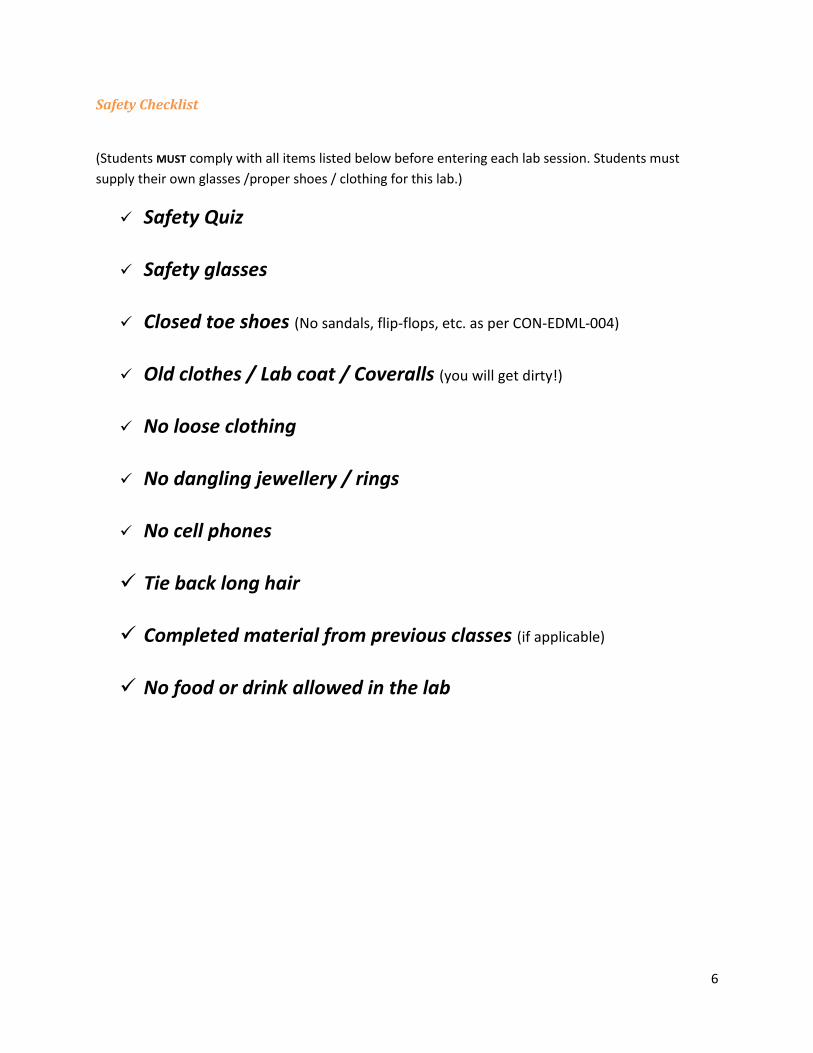
Safety Checklist
(Students MUST comply with all items listed below before entering each lab session. Students must
supply their own glasses /proper shoes / clothing for this lab.)
Safety Quiz
Safety glasses
Closed toe shoes (No sandals, flip-flops, etc. as per CON-EDML-004)
Old clothes / Lab coat / Coveralls (you will get dirty!)
No loose clothing
No dangling jewellery / rings
No cell phones
Tie back long hair
Completed material from previous classes (if applicable)
No food or drink allowed in the lab

7
Metrology
Metrology is a very important part of the design and manufacturing process. Unless numerical values
are specified and measured, one cannot ensure proper fitment between parts. No part can be made
without some form of measurement. In the next section of this lab, you will be introduced to a scale of
measurement used commonly in engineering and manufacturing environments.
Introduction to Vernier Scale
Pierre Vernier (1580-1637) in 1631 invented the linear scale. This scale is one of the simplest to use for
measurement, and offers a fine discrimination. The Vernier scale is used in all modern measuring
devices. Two instruments we will be covering are the Vernier caliper and Micrometer, both of which use
a form of the Vernier scale.
Introduction to Vernier Caliper
The modern Vernier caliper, as shown in the figure above, was invented by Joseph R. Browning and his
father (Fundamentals of Dimensional Metrology 3rd Ed p. 106). Browning went on to form Brown &
Sharp Manufacturing Co., which today is one of the major manufacturers of measuring instruments and
tooling. The Vernier caliper is one of the most versatile measuring tools used by engineers and
machinists. The caliper can be used to measure the following features: linear distances / outside
diameters, internal diameters, and depth.
The steps to measure a part with the Vernier caliper are outlined in the figure below.
8
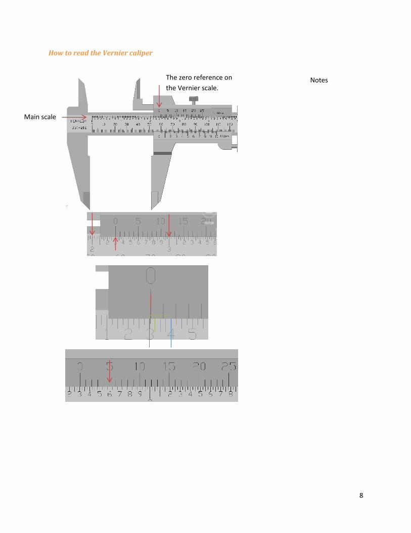
How to read the Vernier caliper
Notes
The zero reference on
the Vernier scale.
Main scale
9
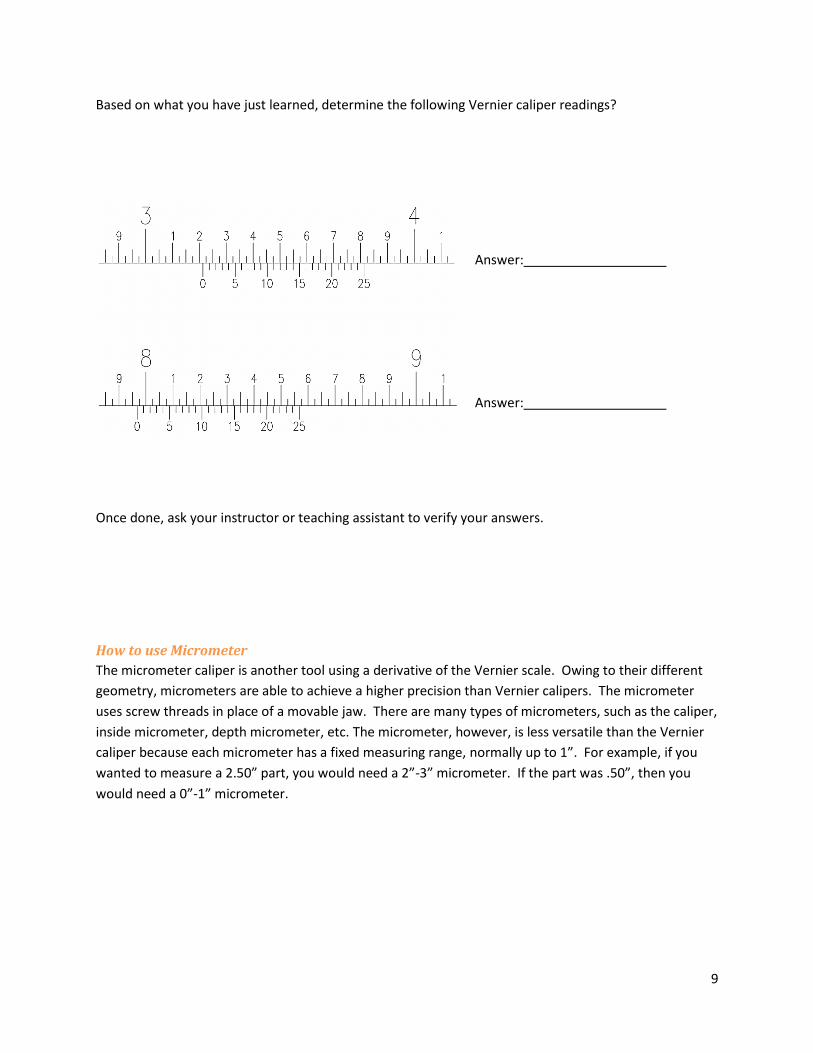
Based on what you have just learned, determine the following Vernier caliper readings?
Answer: Answer:
Once done, ask your instructor or teaching assistant to verify your answers.
How to use Micrometer
The micrometer caliper is another tool using a derivative of the Vernier scale. Owing to their different
geometry, micrometers are able to achieve a higher precision than Vernier calipers. The micrometer
uses screw threads in place of a movable jaw. There are many types of micrometers, such as the caliper,
inside micrometer, depth micrometer, etc. The micrometer, however, is less versatile than the Vernier
caliper because each micrometer has a fixed measuring range, normally up to 1”. For example, if you
wanted to measure a 2.50” part, you would need a 2”-3” micrometer. If the part was .50”, then you
would need a 0”-1” micrometer.

10
The steps to measure a part with the micrometer caliper are outlined in the figure below.
Additionally, your micrometer may be equipped with a Vernier scale, potentially measuring to 4 decimal places (i.e. one ten thousandth of an inch), see figure below.

11
Based on what you have just learned, determine the following micrometer caliper readings.
Answer: Answer:
Once done, ask your instructor or teaching assistant to verify your answers.
12
Inspection of Gyroscope components
Measure Existing Gyroscope
Now that you have been exposed to basic measuring principles, you are required to fill in the missing
dimensions indicated on the following drawings.
Fill in Missing Dimensions
You will be provided with a digital Vernier caliper, and will use this device to record all the missing
dimensions on the technical drawings of the gyroscope components.
Do’s and Don’ts of Using a Digital Caliper
Do:
Treat your caliper with respect, it is a delicate instrument
Turn off caliper after use to preserve battery
Place caliper in its protective case / box when not in use
Unlock the set screw before opening the jaws
Don’t:
Use your caliper as a scriber (i.e. to scratch or mark a surface)
Drop or mistreat / abuse your caliper
Force the jaws of the Vernier caliper open (check the set screw prior to use)
Lay your caliper in a dangerous position, where it could fall
Set it down in a dirty environment, as any foreign object debris (FOD) could damage the
instrument, and subsequently your measurements.
Lay your caliper in coolant as this will distort the measurements.

13
Table 1. Dimensions for Gyroscope Frame
Dimension Value Dimension Value
1 12
2 13
3 14
4 15
5 16
6 17
7 18
8 19
9 20
10 21
11 22

14
Table 2. Dimensions for Gyroscope Rotor
Dimension Value
1
2
3
4
5
6
7

15
Table 3. Dimensions for Gyroscope Shaft
Dimension Value Dimension Value
1 4
2 5
3 6
Once completed, please ensure to have your instructor or TA sign the data sheets. You will use this data
to complete the required technical drawings due for Lab #2.
Assignment #1
Assignment #1 is to create technical drawings of the three measured components. Due at the beginning
of Lab #2.
Each technical drawing must include:
Parts must be drawn using a 3D CAD software. Then 2D technical drawings will be generated.
Minimum 2 views
Sufficient dimensions detailing all aspects of the parts
Correct use of the Concordia titleblock (see below)
Correct scale (1:1)
Proper drawing standards as per MECH 211 and MECH 313 (ASME Y14.5)
Correct Units
Drawing requirements as per
http://www.mie.concordia.ca/facilities/engineering-design-and-manufacturing-lab/resources/drawing-
requirements/
See examples for assistance.
http://www.mie.concordia.ca/facilities/engineering-design-and-manufacturing-lab/self-
learning/examples/

16
Lab Sequence The lab groups are divided into two sub sequences, A and B. This alternates based on when the student
will machine the frame or the rotor, shaft and ring. Your sequence will be assigned during Lab #1.
If you are in Sequence A, follow the labs in this order: 1, 2, 3, 4, 5 & 6
If you are in Sequence B, follow the labs in this order: 1, 4, 5, 2, 3 & 6
Pre-Lab 2
Instructional Video - How to use the Mill
Introduction to the milling machine (anatomy)
3 Axis movement + Quill (Digital Readout)
Guarding and Lighting
Starting and Stopping Procedures
Changing Speeds and Gears
Installing / Removing Tools
Work Holding (Vice, parallels, vice handle)
Establishing reference points. (edge finder)
Cutter Direction (Climb vs. Conventional Milling)
Mill Operating Quiz
Quiz to determine level of student capability. Must get 100% to attend the lab.
Instructional Video – Gyroscope Frame Part 1
Watch Video on how-to machine Frame (Part 1)
Student Requirements
Make notes / process sheet from demonstration to be used during the manufacturing.
Process sheet form on EDML website on useful documents page.
http://www.mie.concordia.ca/facilities/engineering-design-and-manufacturing-
lab/resources/documentation/
Resources
Instructional Video - How to use the Mill – Moodle
Mill Operating Test – Moodle
Gyroscope Frame Part 1 Video – Moodle
Process Sheet Template and Examples – EDML website

17
Lab 2
Machining Frame Part 1
Instructor / TA demonstration – Students to add to notes taken from pre-lab video.
Student manufacturing
Cleaning
Student Requirements
Have instructor or TA verify process sheet before leaving
Pre-Lab 3
Instructional Video – Gyroscope Frame Part 2
Watch Video on how-to machine Frame (Part 2)
How to use the Drill Press Instructional Video
Watch video on operating the drill press and how-to for drilling processes done in the lab.
Drill Press Operating Quiz
Quiz to determine level of student capability. Must get 100% to attend the lab.
Student Requirements
Make notes / process sheet from demonstrations for Frame part 2.
Resources
Gyroscope Frame Part 2 Video – Moodle
Instructional Videos - - How to use the Mill & How to use the Drill Press – Moodle
Drill Press Operating Test – Moodle
Process Sheet Template and Examples – EDML website
Assignment #2
Frame Part 1 process sheet due at the beginning of Lab #3
Lab 3
Machining Frame Part 2
Instructor/TA demonstration – Students to add to notes taken from pre-lab video.
Student manufacturing
Cleaning
Student Requirements
Have instructor or TA verify process sheet before leaving
18
Pre-Lab 4
Instructional Video - How to use the Lathe
Introduction to the lathe
2 Axis movement + Compound Rest (Digital Readout)
Tailstock
Guarding and Lighting
Starting and Stopping Procedures
Changing Speeds (Gears)
Installing / Removing Tools (tool post & Tailstock)
Work Holding (3 Jaw Chuck)
Establishing reference points.
Direction of Rotation (Cutter orientation)
Lathe Operating Quiz
Quiz to determine level of student capability. Must get 100% to attend the lab.
Instructional Video – Gyroscope Rotor
Watch Video on how-to machine rotor
Student Requirements
Make notes / process sheet from demonstration.
Resources
Instructional Video - How to use the Lathe – Moodle
Gyroscope Rotor Video – Moodle
Process Sheet Template and Examples – EDML website
Assignment #3
Frame Part 2 process sheet due at the beginning of Lab #4
Lab 4
Machining Rotor Part 1
Instructor/TA demonstration – Students to add to notes taken from pre-lab video.
Student manufacturing
Cleaning
Student Requirements
Have TA verify process sheet before leaving

19
Pre-Lab 5 Review lathe operational video and rotor demonstration is necessary.
Student Requirements
Make notes / process sheet from demonstration.
Resources
Instructional Video - How to use the Lathe – Moodle
Gyroscope Rotor Video – Moodle
Process Sheet Template and Examples – EDML website
Assignment #4
Rotor process sheet due at the beginning of Lab #5
Lab 5
Machining Rotor Part 2
Complete Rotor if necessary
Instructor/TA demonstration – Students take notes for shaft and ring.
Student manufacturing of ring and shaft
Cleaning
Pre-Lab 6
Assignments #5 & 6
Rotor and shaft process sheets due at the beginning of Lab #6
Lab 6
Computer Numerically Controlled Machining (CNC)
During lab #6, students will be able to observe the functionality of a 3 Axis Milling machine in order to
do an engraving process on the gyroscope frame.
Time permitting, there will also be demonstrations on manufacturing of the gyroscope frame and rotor
via a CNC mill and CNC lathe.
Final Assembly
For the final assembly of the gyroscope, students will be introduced to the use of basic hand tools as
well as the techniques and procedures required to assemble the gyroscope.
20
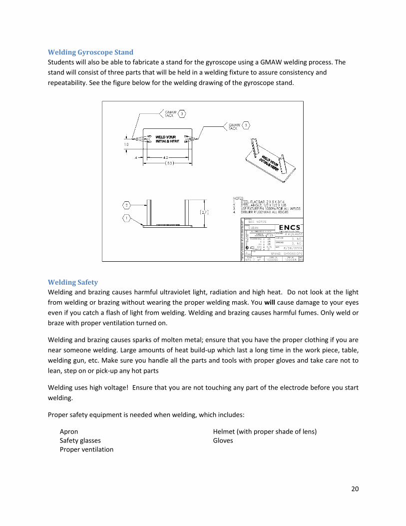
Welding Gyroscope Stand
Students will also be able to fabricate a stand for the gyroscope using a GMAW welding process. The
stand will consist of three parts that will be held in a welding fixture to assure consistency and
repeatability. See the figure below for the welding drawing of the gyroscope stand.
Welding Safety
Welding and brazing causes harmful ultraviolet light, radiation and high heat. Do not look at the light
from welding or brazing without wearing the proper welding mask. You will cause damage to your eyes
even if you catch a flash of light from welding. Welding and brazing causes harmful fumes. Only weld or
braze with proper ventilation turned on.
Welding and brazing causes sparks of molten metal; ensure that you have the proper clothing if you are
near someone welding. Large amounts of heat build-up which last a long time in the work piece, table,
welding gun, etc. Make sure you handle all the parts and tools with proper gloves and take care not to
lean, step on or pick-up any hot parts
Welding uses high voltage! Ensure that you are not touching any part of the electrode before you start
welding.
Proper safety equipment is needed when welding, which includes:
Apron Helmet (with proper shade of lens) Safety glasses Gloves Proper ventilation
21
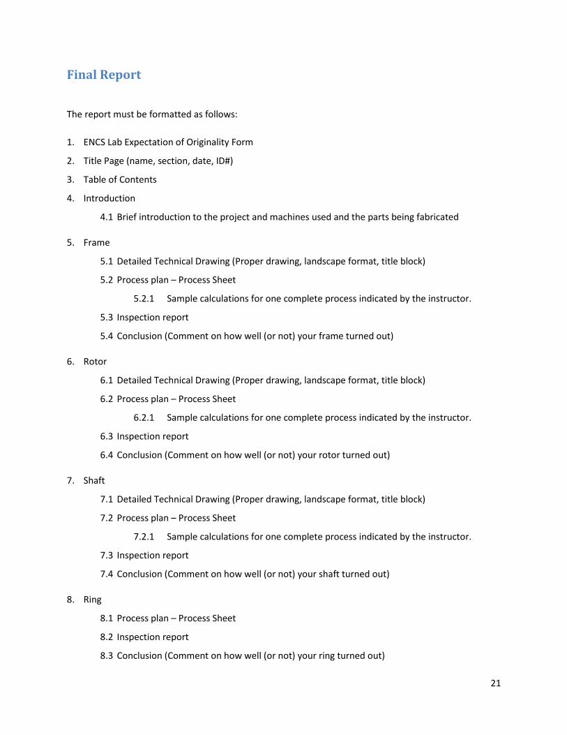
Final Report
The report must be formatted as follows:
1. ENCS Lab Expectation of Originality Form
2. Title Page (name, section, date, ID#)
3. Table of Contents
4. Introduction
4.1 Brief introduction to the project and machines used and the parts being fabricated
5. Frame
5.1 Detailed Technical Drawing (Proper drawing, landscape format, title block)
5.2 Process plan – Process Sheet
5.2.1 Sample calculations for one complete process indicated by the instructor.
5.3 Inspection report
5.4 Conclusion (Comment on how well (or not) your frame turned out)
6. Rotor
6.1 Detailed Technical Drawing (Proper drawing, landscape format, title block)
6.2 Process plan – Process Sheet
6.2.1 Sample calculations for one complete process indicated by the instructor.
6.3 Inspection report
6.4 Conclusion (Comment on how well (or not) your rotor turned out)
7. Shaft
7.1 Detailed Technical Drawing (Proper drawing, landscape format, title block)
7.2 Process plan – Process Sheet
7.2.1 Sample calculations for one complete process indicated by the instructor.
7.3 Inspection report
7.4 Conclusion (Comment on how well (or not) your shaft turned out)
8. Ring
8.1 Process plan – Process Sheet
8.2 Inspection report
8.3 Conclusion (Comment on how well (or not) your ring turned out)

22
9. Assembly Drawing + Assembly Procedure + Bill of Materials
9.1 Bill of Materials (BOM) is a list of all components required to assemble the final product.
Include: quantity, was part purchased or fabricated, drawing number of fabricated parts,
description of parts, etc. The BOM can be included on the assembly drawing if it fits.
9.2 Assembly drawing is a view of the gyroscope with all the components shown as they go
together. (i.e. fully assembled) Each component should be labeled with a number which
corresponds to the same number on the bill of materials. Assembly drawings typically only
have overall dimensions of the assembly and do not have all the dimensions from the
working drawings, although dimensions are not always required on assembly drawings.
Sufficient assembly views should be included to ensure all components are clearly indicated.
Isometric or exploded views are NOT suitable. Include all necessary sections to best
describe the assembly.
9.3 Assembly Procedure is a detailed step by step guide for workers on how to assemble the
product. Imagine you are writing these steps for someone that has never seen it before.
10. Overall conclusion
10.1 How did your gyroscope turn out? Any problems?
10.2 Any comments on how the lab should be improved for future sessions?
Useful Documents
Please visit the useful documents page of the EDML website:
http://www.mie.concordia.ca/facilities/engineering-design-and-manufacturing-
lab/resources/documentation/
For all forms and templates required for this lab.