
mecaniques CCVI... · 5 symbols and units in the catalogue load feature life factor temperature...
68
Transcript of mecaniques CCVI... · 5 symbols and units in the catalogue load feature life factor temperature...


contents
Symbols and units in the catalogue
Engineering data - Spherical plain bearings
Spherical plain bearings
GE...E / GE...ES/GE...ES 2RS Series
GEZ...ES / GEZ...ES 2RS Series
GE...LO Series
GE...HO 2RS Series
GE...FO / GE...FO 2RS Series
GE...UK / GE...UK 2RS Series
GE...FW / GE...FW 2RS Series
PB Series
Angular contact spherical plain bearings
GE...SX Series
GE...SW Series
Spherical plain bearings
COM Series
COM...T Series
Engineering data - Rod Ends
Metric Rod Ends
KMDV / KFDV / KFDV...-1 Series
COS / SCOS / CHS / CHS...-1 / SCHS Series
GIR...DO / GIR...DO 2RS / GAR...DO / GAR...DO 2RS Series
GIR...UK / GIR...UK 2RS / GAR...UK / GAR...UK 2RS Series
POS...HD / SPOS...HD / PHS...HD / PHS...-1 HD / SPHS...HD Series
POS / SPOS / PHS / PHS...-1 / SPHS Series
Metric Injection Rod Ends
COS..N / CHS..N Series
Inch Commercial Rod Ends
EM / EMA / EF/EFA Series
MA / FA Series
Inch Precision Rod Ends
MC / MCB / FC / FCB Series
Inch Injection Rod Ends
MCN / FCN Series
5
6 - 19
20
21
22
23
24
25
26
27
28
29
30
31
32 - 39
40 - 41
42 - 43
44 - 45
46 - 47
48 - 49
50 - 51
52 - 53
54 - 57
58 - 59
60 - 63
64 - 65
CCVI reserve the right to amend this catalogue without prior notice or consultation.
5
symbols and units in the catalogue
load feature life factortemperature life factorsliding speed life factorbearing quality and lubrication life factorshaft washer nominal widthtemperature factorload type factorhousing washer nominal widthbasic static load ratingdynamic load ratingdynamic radial load ratingdynamic axial load ratingstatic radial load ratingstatic axial load ratingsliding spherical surface nominal diameterequivalent diameter of sliding spherical surfacebearing housing bore or outer ring outer diameterouter ring raceway diameterinner ring raceway diameteroscillation frequencyload rating factor of thrust spherical plain bearingsload rating factor of angular contact spherical plain bearingsload rating factor of radial spherical plain bearingsstatic load rating factorload rating factor of radial spherical plain bearingsaxial or radial bearing loadnominal width of thrust spherical plain bearingspressure coefficientfactor related to friction couple materialbasic rating life (oscillation times)basic rating life (hours)relubrication lifebearing friction torqueload division numbernominal contact pressurebearing dynamic equivalent loadmax allowed load of rod endrotary clearance of unloaded bearing after mountingradial internal clearancenominal width of angular contact spherical plain bearinginner ring temperatureouter ring temperaturetheoretical interference amount of the part fitted with the shaftsliding speedload factorlinear heat expansion coefficientrelubrication interval life factorrelubrication oscillation angle life factoroscillation anglefriction factorinner ring expansion amountinternal radial clearance decreasing amount caused by fitinternal radial clearance decreasing amount caused by temperature riseouter ring shrink amount
ak
aT
aV
aZ
Bb2
b6
CC0
Cd
Cdr
Cda
Csr
Csa
dmdmDEFffafrnfTfsfrFa,Fr
HkKm
LLh
LR
MnpPPperm
ssr
TTIR
ToR
UVy�
�h
��
�
�
� d� sp
� sT
�D
mm
mmNNNNNNmmmmmmmmmmmin-1
Nmm
106
h
mm
N/mm2
NN�m�mmmOCOC
m/s
K-1
�
�m�m�m�m
6
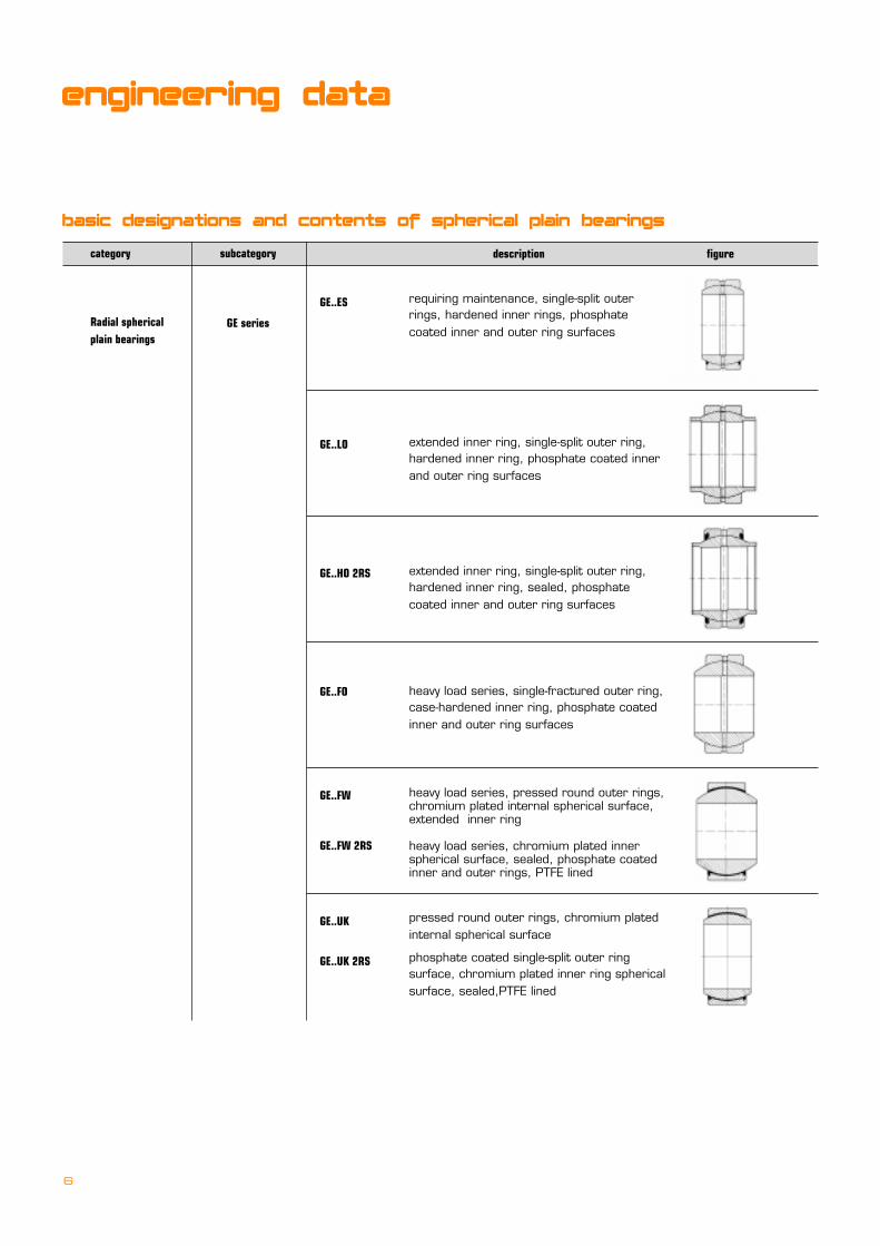
basic designations and contents of spherical plain bearings
category
Radial sphericalplain bearings
subcategory
GE series
description figure
GE..ES
GE..LO
GE..HO 2RS
GE..FO
GE..FW
GE..FW 2RS
GE..UK
GE..UK 2RS
requiring maintenance, single-split outerrings, hardened inner rings, phosphatecoated inner and outer ring surfaces
extended inner ring, single-split outer ring,hardened inner ring, phosphate coated innerand outer ring surfaces
extended inner ring, single-split outer ring,hardened inner ring, sealed, phosphatecoated inner and outer ring surfaces
heavy load series, single-fractured outer ring,case-hardened inner ring, phosphate coatedinner and outer ring surfaces
heavy load series, pressed round outer rings,chromium plated internal spherical surface,extended inner ring
heavy load series, chromium plated innerspherical surface, sealed, phosphate coatedinner and outer rings, PTFE lined
pressed round outer rings, chromium platedinternal spherical surface
phosphate coated single-split outer ringsurface, chromium plated inner ring sphericalsurface, sealed,PTFE lined
engineering data
7
division
Radial sphericalplain bearings
angular contactspherical plainbearings
subdivision
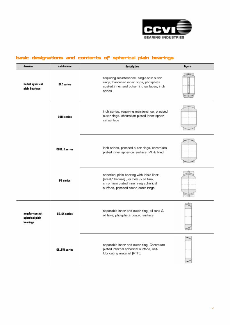
GEZ series
COM series
COM..T series
PB series
GE..SX series
GE..SW series
description figure
requiring maintenance, single-split outerrings, hardened inner rings, phosphatecoated inner and outer ring surfaces, inchseries
inch series, requiring maintenance, pressedouter rings, chromium plated inner spheri-cal surface
inch series, pressed outer rings, chromiumplated inner spherical surface, PTFE lined
spherical plain bearing with inlaid liner(steel/ bronze) , oil hole & oil tank,chromium plated inner ring sphericalsurface, pressed round outer rings
separable inner and outer ring, oil tank &oil hole, phosphate coated surface
separable inner and outer ring, Chromiumplated internal spherical surface, self-lubricating material (PTFE)
basic designations and contents of spherical plain bearings
8
bearing load and life
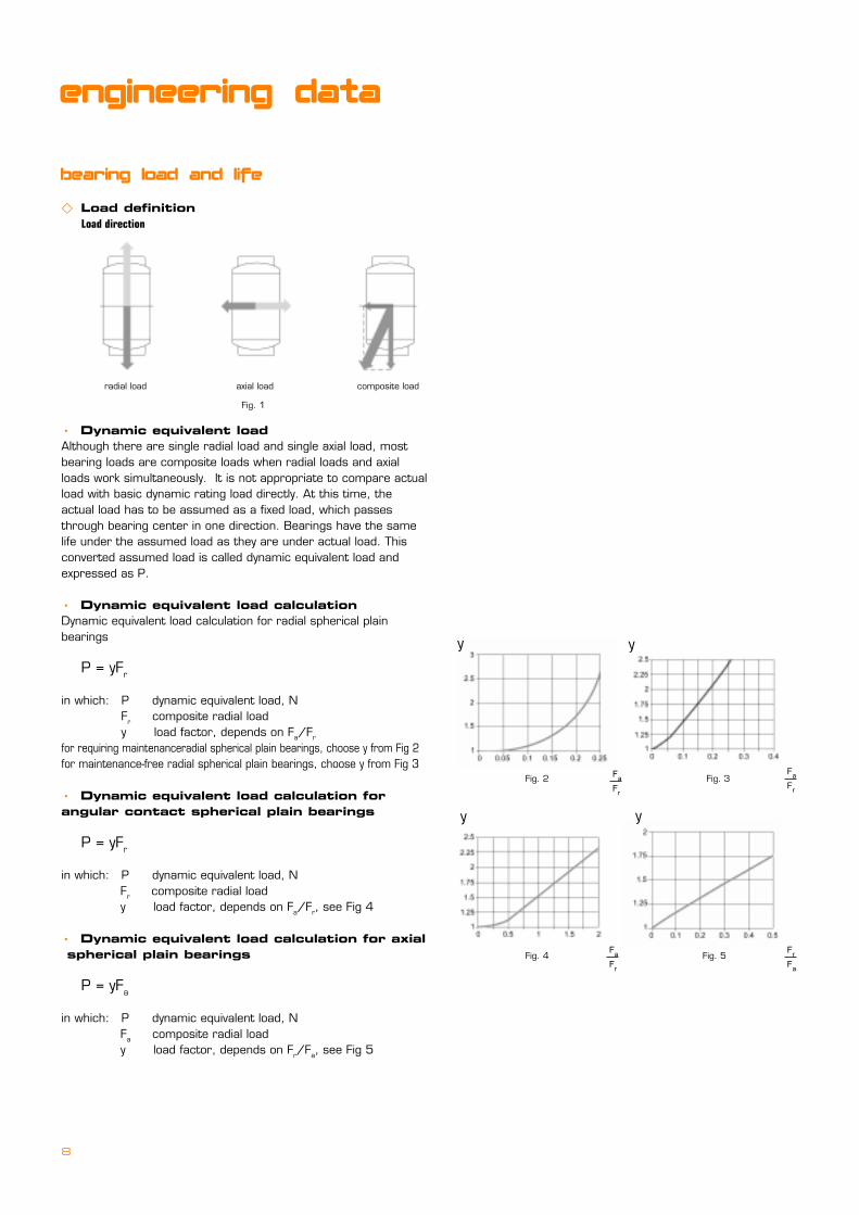
� Load definition Load direction
�==Dynamic equivalent loadAlthough there are single radial load and single axial load, mostbearing loads are composite loads when radial loads and axialloads work simultaneously. It is not appropriate to compare actualload with basic dynamic rating load directly. At this time, theactual load has to be assumed as a fixed load, which passesthrough bearing center in one direction. Bearings have the samelife under the assumed load as they are under actual load. Thisconverted assumed load is called dynamic equivalent load andexpressed as P.
�==Dynamic equivalent load calculationDynamic equivalent load calculation for radial spherical plainbearings
P = yFr
in which: P dynamic equivalent load, N Fr= composite radial load y load factor, depends on Fa/Fr
for requiring maintenanceradial spherical plain bearings, choose y from Fig 2for maintenance-free radial spherical plain bearings, choose y from Fig 3
�==Dynamic equivalent load calculation forangular contact spherical plain bearings
P = yFr
in which: P dynamic equivalent load, N�� Fr= composite radial load�� y load factor, depends on Fa/Fr, see Fig 4
�==Dynamic equivalent load calculation for axial spherical plain bearings
P = yFa
in which: P dynamic equivalent load, N�� Fa= composite radial load�� y load factor, depends on Fr/Fa, see Fig 5
Fig. 1
radial load axial load composite load
engineering data
Fig. 3F
a
Fr
y
Fig. 5F
r
Fa
y
Fig. 2 Fa
Fr
y
Fig. 4F
a
Fr
y

9
� Dynamic load rating calculation for spherical plain bearings
�==radials spherical plain bearings
Dynamic radial load rating of radial spherical plain bearing Cdr:
��Cdr=frCdm
in which: fr load rating factor, see table 1
���� C outer ring (housing washer) nominal width, mm
���� dm sliding spherical surface nominal diameter, mm
���� Cdr dynamic radial load rating, N
�==Angular contact spherical plain bearings
Dynamic radial load rating of angular contact spherical plain bearing Cdr:
Cdr=frn( B+C-T )dm
in which: frn load rating factor of angular contact spherical plain bearing, see table 2
B shaft washer nominal width of spherical plain bearing, mm
T nominal width of angular contact spherical plain bearing, mm
�==Axial spherical plain bearings
dynamic radial load rating of axial spherical plain bearing, Cda:
Cda=fa( B+C-H )�dm
in which: Cda dynamic axial load rating of spherical
plain bearing, N
fa load rating factor of axial spherical plain
bearing, N/ mm2 , see table 3
H nominal width of axial spherical plain
bearing, mm
dm material of friction couple
over to steel/steel steel/PTFE foil steel/PTFE fabric liner steel/ PTFE
5
400
500
700
400
500
700
1200
85
87
90
93
120
125
136
138
90
-
-
-
Table 1 load rating factors of radial spherical plain bearings
50
-
-
-
dm material of friction couple
over to steel/steel steel/PTFE fabric liner
5
55
55
500
85.5
88
128
132
Table 2 Load rating factor of angular contact spherical plain bearings
dm material of friction couple
over to steel/steel steel/PTFE fabric liner
5
60
110
150
220
300
500
60
110
150
220
300
500
700
170
185
190
180
155
143
-
255
280
288
275
230
222
256
Table 3 load rating factor of thrust spherical plain bearings

10
engineering data
� Life calculation of spherical plain bearings
�==Sliding speed of bearing spherical surface
Sliding speed of the working spherical surface of spherical plain bearing is:
V=2.9089x10⁻⁴ �f dm
in which: V sliding speed of spherical plain bearing�mm/s
� oscillation angle, �
f oscillation frequency of spherical plain bearing, min-1
dm equivalent diameter of the sliding spherical surface, mm(dm =� dm), � is the conversed factor, see table 4
�==Nominal contact pressure
Nominal contact pressure of spherical plain bearing is calculated as:
p=k ( P/Cd )
in which: p nominal contact pressure N/mm2
k pressure coefficient, see table 5
P dynamic equivalent load of spherical plain bearing, N
Cd dynamic rating load of spherical plain bearing, N
�==Bearing limit pV valuepV value on the working surface of spherical plain bearing must be limited, otherwise bearing will become over heated and bearing life
will be reduced. pV value is calculated as:
====pV=2.9089x10⁻⁴k�f dm (P/Cd) (N/mm2)�(mm/s)
Limited pV values of different contact couple materials are listed in table 6
material of friction couple steel/steel steel/PTFE foil steel/PTFE fabric liner steel/ PTFE
V
p
pV
Table 6 limited pV values of different contact couple materials
100
100
400
100
50
400
300
150
300
300
100
300
bearing type radial bearing angular contact bearing thrust bearing
�
Table 4 Equivalent diameter of the sliding spherical surface
1 0.9 0.7
100
material of friction couple steel/steel steel/PTFE foil steel/PTFE fabric liner steel/ PTFE
k
Table 5 pressure coefficient
100 50 150

11
�==Life calculation of spherical plain bearings
The calculated life of spherical plain bearings is:
L= �k��T��p��V��Z�=( KMCd/VP )
in which : L the first-time lubrication life of spherical plain bearing, r
� k load feature life factor (see table 7)
� T temperature life factor (see table 7)
� p load life factor
� V sliding speed life factor (see table 7)
� Z bearing quality and lubrication life factor (see table 9)
KM Factor related to friction couple material (see table 7)
Table 8 G, b values
P material of friction couple
over to steel/steel steel/PTFE foil steel/PTFE fabric liner steel/ PTFE
0
10
25
45
65
100
10
25
45
65
100
150
G
2
80.533
80.533
80.533
80.533
-
b
0
1.465
1.465
1.465
1.465
-
G
0.25
1
1
-
-
-
b
0
0.6
0.6
-
-
-
G
15.3460
15.3460
22.9060
47.7259
157.9193
402.0115
b
0.0488
0.0488
0.1732
0.3660
0.6527
0.8556
G
4.5102
4.5102
13.7170
13.7170
13.7170
-
b
0.2230
0.2230
0.5686
0.5686
0.5686
-
material of friction couple grease lubrication self-lubrication
without oil tank with oil tank
� Z
Table 9 Bearing quality and lubrication life factor
0.1-0.5 0.5-10.3-1
steel/steel steel/PTFE foil steel/PTFE fabric liner steel/ PTFE
KM
� k
� T
� V
� P
a
Table 7
830
1
1
2
1
0.9
0.8
0.6
V 0.86 �0.84 f 0.64
-
207600
1
1
2
1
1.15-2.5x10⁻³ t
2.1-0.012 t
-
V 0.4 f 0.8
-
2.592x10⁵
1
0.6062-6.0207x10⁻³ fpp1.11
0.433-4.3005x10⁻³ fpp1.11
1
1.225-3.75x10⁻³
1.35-0.005t
-
f/(1.00475)av�1.0093�
G/Pb
1.0139p
2.946x10⁵
1
0.6062-3.1309x10⁻³fpp1.25
0.433-2.2364x10⁻³fpp1.25
1
2.2-0.02t
-
-
f/(1.00344)av
1.0399p
note: see table 8 for G and b values in the table

12
engineering data
�==Relubrication life calculation method
For grease lubricated spherical plain bearing, the lubricant should be replaced periodically. The bearing life evaluation method is as:
LR=�h�� L
in which: LR relubricating life of spherical plain bearing, r
�h relubricating interval life factor, see table 10
�� relubricating oscillation angle life factor, see table 11
LW relubricating period, r
L initial lubricating life of spherical plain bearing, r
�==When bearing under interval load, the life calculation formula is:
====L=T/�( Ti/Li )
in which: Ti acting time of the ith time interval
Li calculated life of the ith time interval
====L=T/ � Ti
==== n Interval number of the load
� Calculation method of static load rating of spherical plain bearings
�==Radial spherical plain bearings
Under normal clearance condition, the static load rating of spherical plain bearing is:
��
Csr=fs�C�dm��
in which: Csr static load rating , N
�� fs static load rating factor, see table 12
�� C outer ring (housing washer) nominal width of spherical plain bearing, mm
�� dm sliding spherical surface nominal diameter of spherical plain bearing, mm
n
i=1
n
i=1
h=L/LW 1 5 10 20 30 40 50
Table 10 Relubricating interval life factor
� h 1 2 2.85 4 4.9 5.45 5.45
�(o) �7 10 15 20 25 30 35 40
Table 11 Relubricating oscillation angle life facto
�� 0.8 1 2.4 3.7 4.6 5.2 5.2 5.2
13
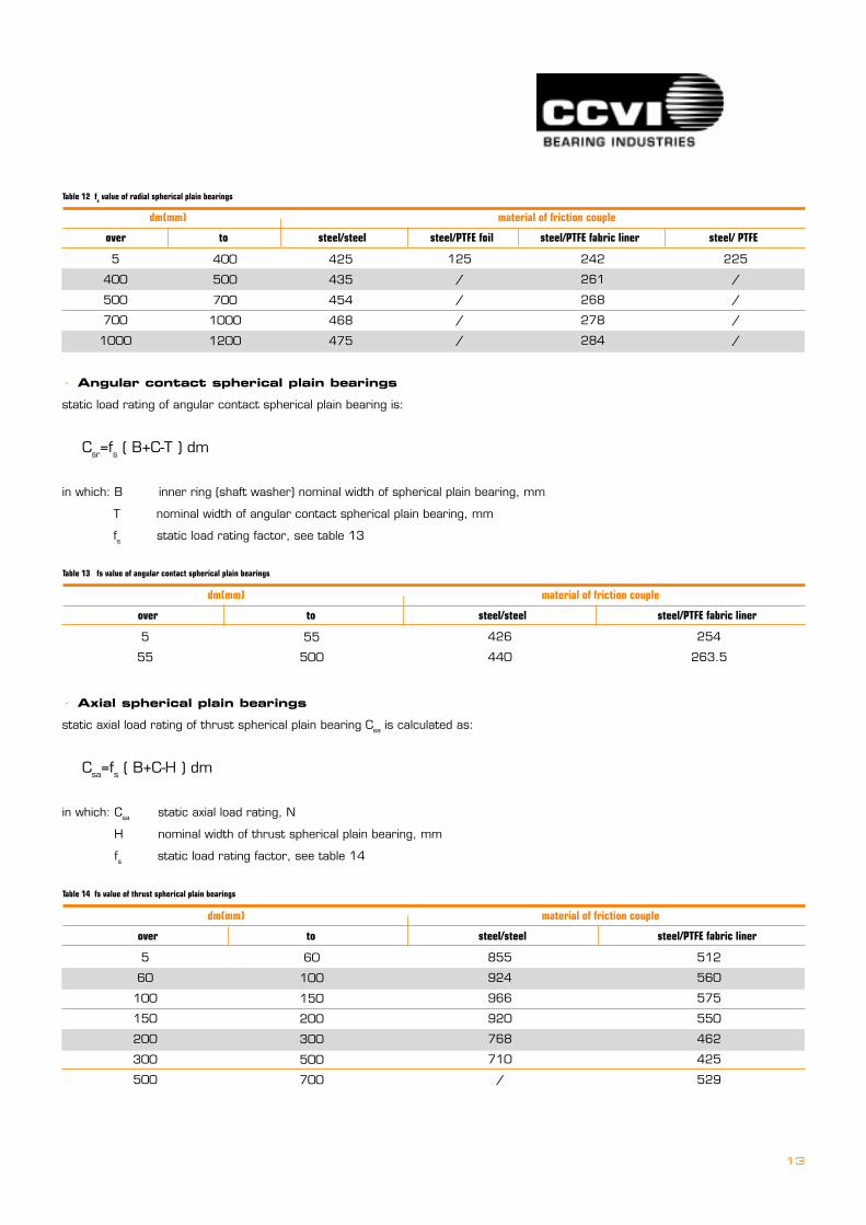
Table 12 fs value of radial spherical plain bearings
dm(mm) material of friction couple
over to steel/steel steel/PTFE foil steel/PTFE fabric liner steel/ PTFE
5
400
500
700
1000
400
500
700
1000
1200
425
435
454
468
475
125
/
/
/
/
242
261
268
278
284
225
/
/
/
/
� Angular contact spherical plain bearings
static load rating of angular contact spherical plain bearing is:
��
Csr=fs ( B+C-T ) dm
in which: B inner ring (shaft washer) nominal width of spherical plain bearing, mm
�� T nominal width of angular contact spherical plain bearing, mm
�� fs static load rating factor, see table 13
� Axial spherical plain bearings
static axial load rating of thrust spherical plain bearing Csa is calculated as:
��
Csa=fs ( B+C-H ) dm
in which: Csa static axial load rating, N
H nominal width of thrust spherical plain bearing, mm
fs static load rating factor, see table 14
Table 13 fs value of angular contact spherical plain bearings
dm(mm) material of friction couple
over to steel/steel steel/PTFE fabric liner
5
55
55
500
426
440
254
263.5
Table 14 fs value of thrust spherical plain bearings
dm(mm) material of friction couple
over to steel/steel steel/PTFE fabric liner
5
60
100
150
200
300
500
60
100
150
200
300
500
700
855
924
966
920
768
710
/
512
560
575
550
462
425
529
14
engineering data
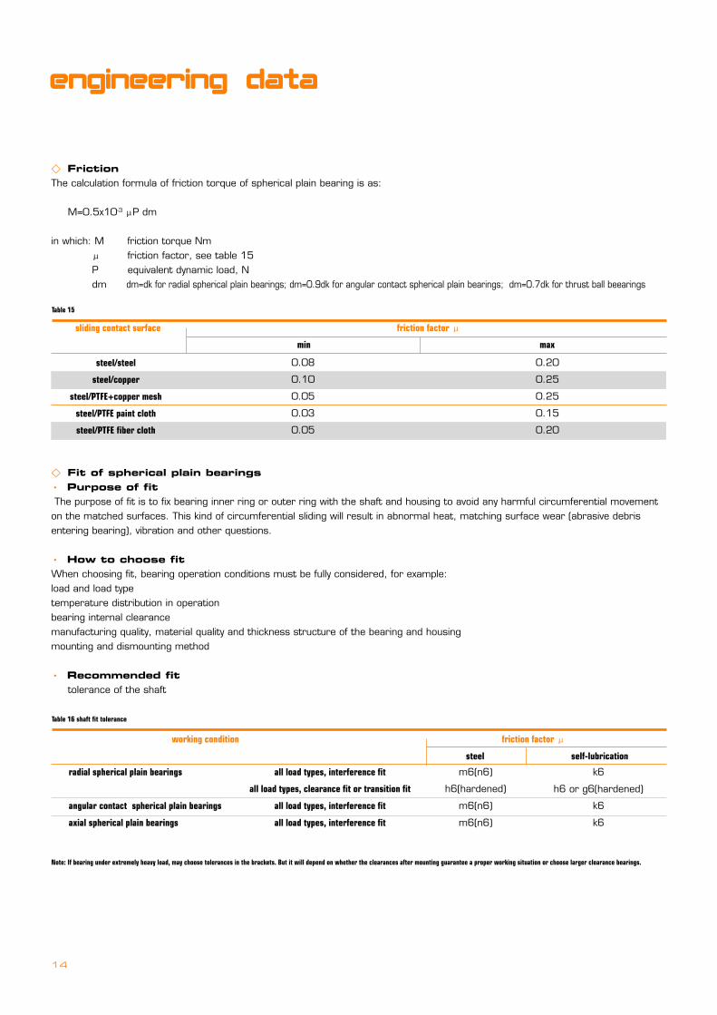
� FrictionThe calculation formula of friction torque of spherical plain bearing is as:
M=0.5x10⁻³ �P dm
in which: M friction torque Nm � friction factor, see table 15
P equivalent dynamic load, N dm dm=dk for radial spherical plain bearings; dm=0.9dk for angular contact spherical plain bearings; dm=0.7dk for thrust ball beearings
� Fit of spherical plain bearings�==Purpose of fit The purpose of fit is to fix bearing inner ring or outer ring with the shaft and housing to avoid any harmful circumferential movementon the matched surfaces. This kind of circumferential sliding will result in abnormal heat, matching surface wear (abrasive debrisentering bearing), vibration and other questions.
�==How to choose fitWhen choosing fit, bearing operation conditions must be fully considered, for example:load and load typetemperature distribution in operationbearing internal clearancemanufacturing quality, material quality and thickness structure of the bearing and housingmounting and dismounting method
�==Recommended fit tolerance of the shaft
Table 15
sliding contact surface friction factor �
min max
steel/steel
steel/copper
steel/PTFE+copper mesh
steel/PTFE paint cloth
steel/PTFE fiber cloth
0.08
0.10
0.05
0.03
0.05
0.20
0.25
0.25
0.15
0.20
Table 16 shaft fit tolerance
working condition friction factor �
steel self-lubrication
radial spherical plain bearings
angular contact spherical plain bearings
axial spherical plain bearings
k6
h6 or g6(hardened)
k6
k6
m6(n6)
h6(hardened)
m6(n6)
m6(n6)
all load types, interference fit
all load types, clearance fit or transition fit
all load types, interference fit
all load types, interference fit
Note: If bearing under extremely heavy load, may choose tolerances in the brackets. But it will depend on whether the clearances after mounting guarantee a proper working situation or choose larger clearance bearings.
15
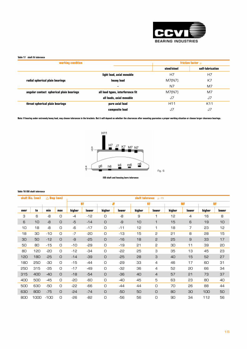
Table 17 shaft fit tolerance
working condition friction factor �
steel/steel self-lubrication
radial spherical plain bearings
angular contact spherical plain bearings
thrust spherical plain bearings
H7
K7
M7
M7
J7
K11
J7
H7
M7(N7)
N7
M7(N7)
J7
H11
J7
light load, axial movable
heavy load
-
all load types, interference fit
all loads, axial movable
pure axial load
composite load
Note: If bearing under extremely heavy load, may choose tolerances in the brackets. But it will depend on whether the clearances after mounting guarantee a proper working situation or choose larger clearance bearings.
ISO shaft and housing bore tolerance
shaft Dia. (mm) � Dmp (mm) shaft tolerance �m
HF JF KF MF NF
3
6
10
18
30
50
80
120
180
250
315
400
500
630
800
over to min max
6
10
18
30
50
80
120
180
250
315
400
500
630
800
1000
-8
-8
-8
-10
-12
-15
-20
-25
-30
-35
-40
-45
-50
-75
-100
0
0
0
0
0
0
0
0
0
0
0
0
0
0
0
higher
-4
-5
-6
-7
-9
-10
-12
-14
-15
-17
-18
-20
-22
-24
-26
lower
-12
-14
-17
-20
-25
-29
-34
-39
-44
-49
-54
-60
-66
-74
-82
higher
0
0
0
0
0
0
0
0
0
0
0
0
0
0
0
lower
-8
-9
-11
-13
-16
-19
-22
-25
-29
-32
-36
-40
-44
-50
-56
higher
9
10
12
15
18
21
25
28
33
36
40
45
44
50
56
lower
1
1
1
2
2
2
3
3
4
4
4
5
0
0
0
higher
12
15
18
21
25
30
35
40
46
52
57
63
70
80
90
lower
4
6
7
8
9
11
13
15
17
20
21
23
26
30
34
higher
16
19
23
28
33
39
45
52
60
66
73
80
88
100
112
lower
8
10
12
15
17
20
23
27
31
34
37
40
44
50
56
Table 18 ISO shaft tolerance
Fig. 6

16
� Lubrication and seal�==Self-lubricating bearingThe combined types of sliding contact surfaces of CCVI self-lubricating
spherical plain bearings have six kinds:
===�steel/copper
===�steel/PTFE fiber cloth
===�steel/PTFE paint cloth
===�steel/PTFE composite material + copper mesh
===�steel/PTFE sintered bronze composite material(BK-1)
===�steel/nylon
�==Oil lubrication / Grease lubricationRadial spherical plain bearings with steel/steel sliding contact surfaces
must be lubricated. The purpose of lubrication is that:
�= Reduce friction and wearPrevent metal contacts on bearing rings and reduce friction
�==Extend fatigue lifeGood lubrication on the contact surfaces will extend bearing fatigue
life; otherwise, lower viscosity and uneven-distributed lubricating oil film
will shorten bearing life.
�==Rust resistance
relubricating through bearing outer ring relubricating through bearing inner ring
Fig.7
engineering data
housing bore (mm) � Dmp (mm) shaft tolerance �m
HF JF KF MF NF
10
18
30
50
80
120
150
180
250
315
400
500
630
800
over to max min
18
30
50
80
120
150
180
250
315
400
500
630
800
1000
-8
-9
-11
-13
-15
-18
-25
-30
-35
-40
-45
-50
-75
-100
0
0
0
0
0
0
0
0
0
0
0
0
0
0
lower
0
0
0
0
0
0
0
0
0
0
0
0
0
0
higher
18
21
25
30
35
40
40
46
52
57
63
70
80
90
lower
-8
-9
-11
-12
-13
-14
-14
-16
-16
-18
-20
-
-
-
lower
10
12
14
18
22
26
26
30
36
39
43
-
-
-
lower
-12
-15
-18
-21
-25
-28
-28
-33
-36
-40
-45
-70
-80
-90
lower
6
6
7
9
10
12
13
16
17
18
0
0
0
0
lower
-18
-21
-25
-30
-35
-40
-40
-46
-52
-57
-63
-96
-110
-124
lower
0
0
0
0
0
0
0
0
0
0
0
-26
-30
-34
lower
-23
-28
-33
-39
-45
-52
-52
-60
-66
73
-80
-114
-130
-146
lower
-5
-7
-8
-9
-10
-12
-12
-14
-14
-16
-17
-44
-50
-56
Table 19 ISO shaft tolerance
�==Prevent outside external substance entering bearing and take wear debris out of bearing.
17
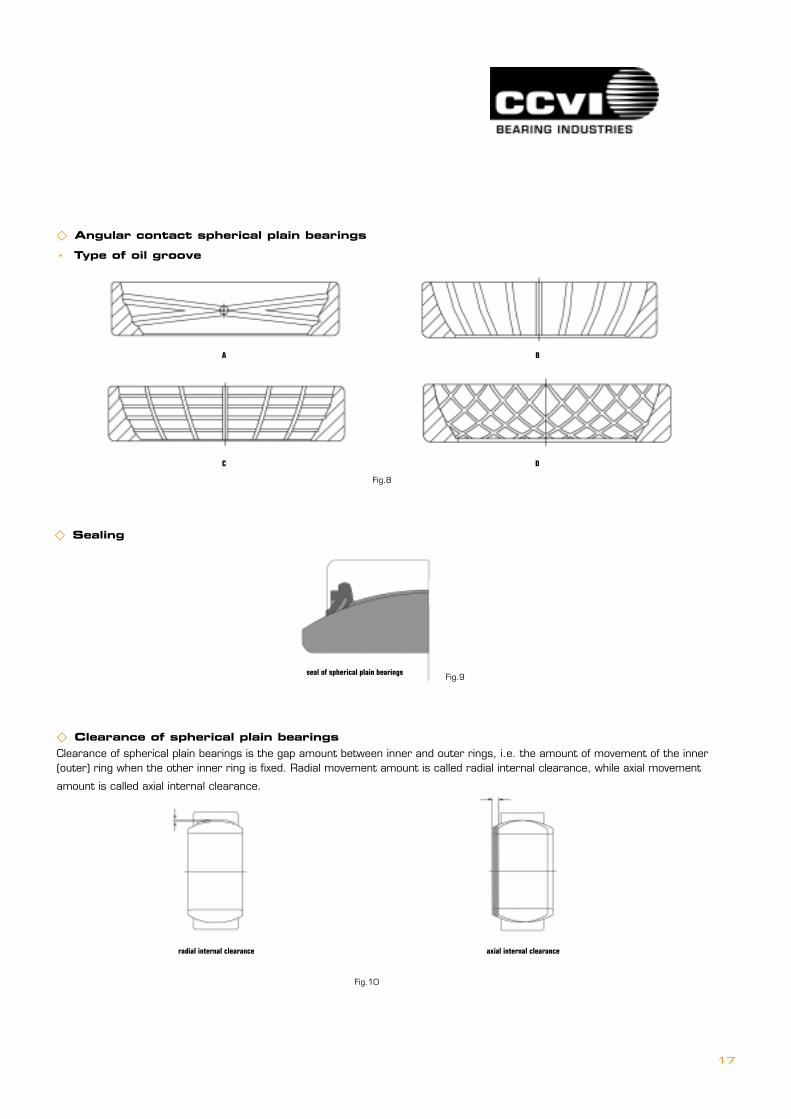
� Clearance of spherical plain bearingsClearance of spherical plain bearings is the gap amount between inner and outer rings, i.e. the amount of movement of the inner(outer) ring when the other inner ring is fixed. Radial movement amount is called radial internal clearance, while axial movement
amount is called axial internal clearance.
radial internal clearance axial internal clearance
seal of spherical plain bearings
� Angular contact spherical plain bearings
�==Type of oil groove
� Sealing
Fig.9
Fig.10
Fig.8
A B
C D
18
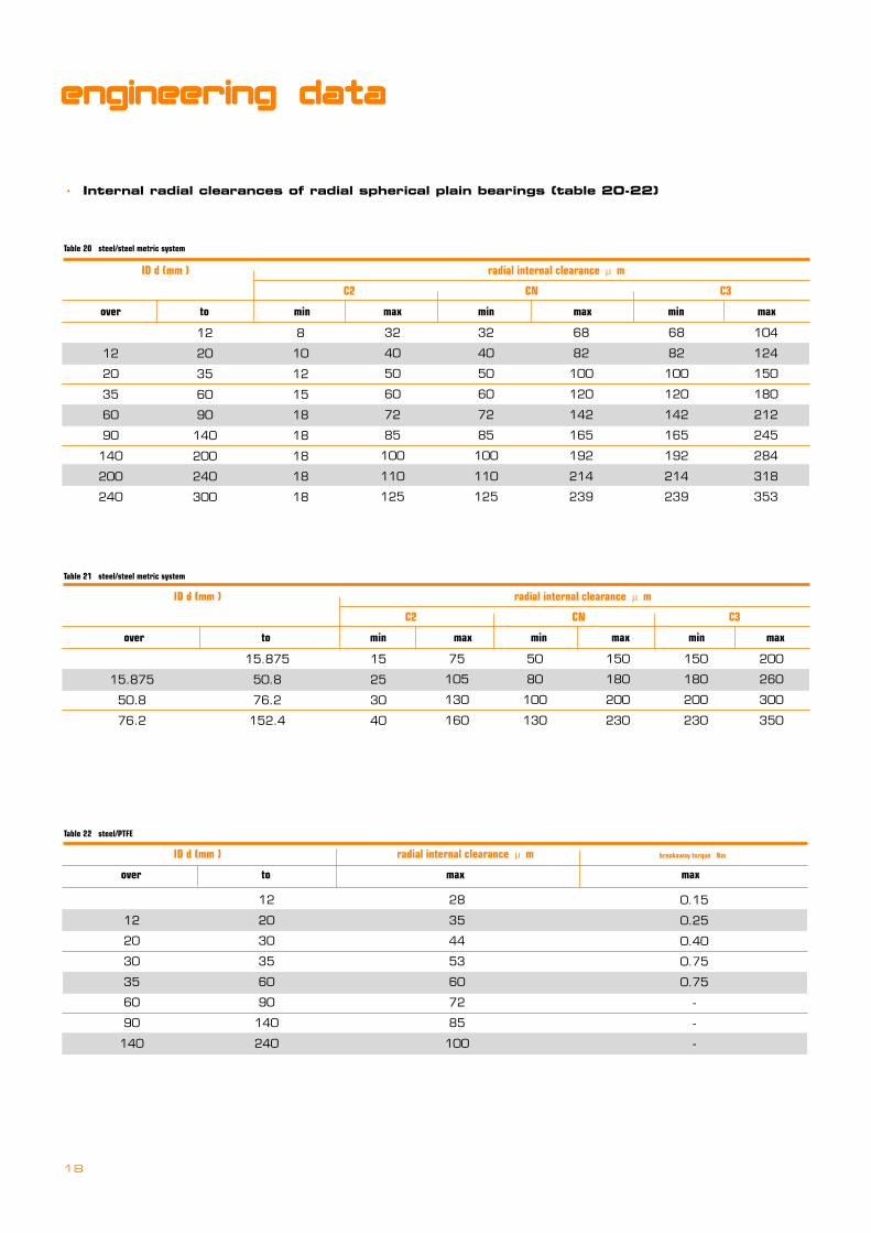
�==Internal radial clearances of radial spherical plain bearings (table 20-22)
engineering data
ID d (mm ) radial internal clearance � m
C2 CN C3
over to min max min max min max
12
20
35
60
90
140
200
240
8
10
12
15
18
18
18
18
18
32
40
50
60
72
85
100
110
125
32
40
50
60
72
85
100
110
125
68
82
100
120
142
165
192
214
239
68
82
100
120
142
165
192
214
239
104
124
150
180
212
245
284
318
353
Table 20 steel/steel metric system
12
20
35
60
90
140
200
240
300
ID d (mm ) radial internal clearance � m
C2 CN C3
over to min max min max min max
15.875
50.8
76.2
15.875
50.8
76.2
152.4
15
25
30
40
Table 21 steel/steel metric system
75
105
130
160
50
80
100
130
150
180
200
230
150
180
200
230
200
260
300
350
ID d (mm ) radial internal clearance � m breakaway torque Nm
over to max max
12
20
30
35
60
90
140
12
20
30
35
60
90
140
240
28
35
44
53
60
72
85
100
Table 22 steel/PTFE
0.15
0.25
0.40
0.75
0.75
-
-
-
19
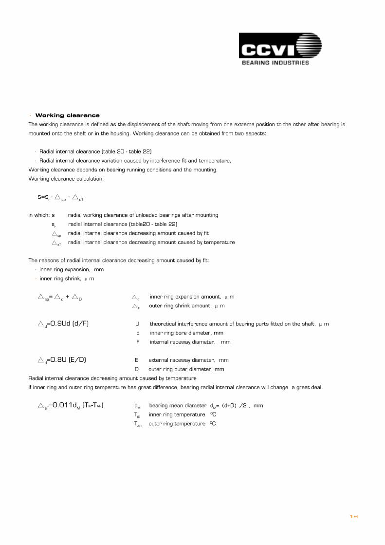
� Working clearance
The working clearance is defined as the displacement of the shaft moving from one extreme position to the other after bearing is
mounted onto the shaft or in the housing. Working clearance can be obtained from two aspects:
� Radial internal clearance (table 20 - table 22)
� Radial internal clearance variation caused by interference fit and temperature,
Working clearance depends on bearing running conditions and the mounting.
Working clearance calculation:
s=sr -� sp - � sT
in which: s radial working clearance of unloaded bearings after mounting
sr radial internal clearance (table20 - table 22)
� sp radial internal clearance decreasing amount caused by fit
� sT radial internal clearance decreasing amount caused by temperature
The reasons of radial internal clearance decreasing amount caused by fit:
� inner ring expansion, mm
� inner ring shrink, �m
� sp=� d + �D � d inner ring expansion amount, �m
�D outer ring shrink amount, �m
� d=0.9Ud (d/F) U theoretical interference amount of bearing parts fitted on the shaft, �m
d inner ring bore diameter, mm
F internal raceway diameter, mm
� d=0.8U (E/D) E external raceway diameter, mm
D outer ring outer diameter, mm
Radial internal clearance decreasing amount caused by temperature
If inner ring and outer ring temperature has great difference, bearing radial internal clearance will change a great deal.
� sT=0.011dM (TIR-TAR) dM bearing mean diameter dM=�d+D�/2 �mm
TIR inner ring temperature 0C
TAR outer ring temperature 0C
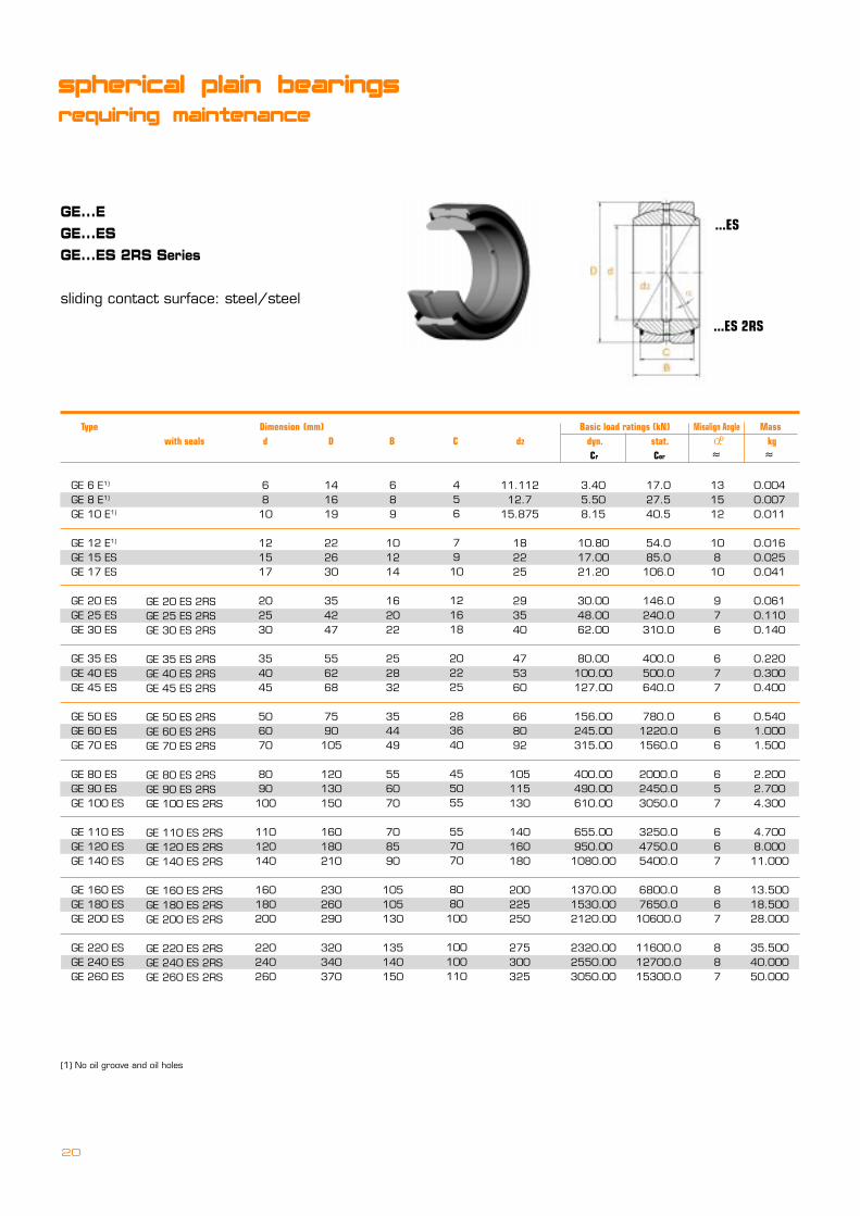
GE...EGE...ESGE...ES 2RS Series
sliding contact surface: steel/steel
...ES
...ES 2RS
(1) No oil groove and oil holes
GE 6 E1)
GE 8 E1)
GE 10 E1)
GE 12 E1)
GE 15 ESGE 17 ES
GE 20 ESGE 25 ESGE 30 ES
GE 35 ESGE 40 ESGE 45 ES
GE 50 ESGE 60 ESGE 70 ES
GE 80 ESGE 90 ESGE 100 ES
GE 110 ESGE 120 ESGE 140 ES
GE 160 ESGE 180 ESGE 200 ES
GE 220 ESGE 240 ESGE 260 ES
GE 20 ES 2RSGE 25 ES 2RSGE 30 ES 2RS
GE 35 ES 2RSGE 40 ES 2RSGE 45 ES 2RS
GE 50 ES 2RSGE 60 ES 2RSGE 70 ES 2RS
GE 80 ES 2RSGE 90 ES 2RSGE 100 ES 2RS
GE 110 ES 2RSGE 120 ES 2RSGE 140 ES 2RS
GE 160 ES 2RSGE 180 ES 2RSGE 200 ES 2RS
GE 220 ES 2RSGE 240 ES 2RSGE 260 ES 2RS
689
101214
162022
252832
354449
556070
708590
105105130
135140150
6810
121517
202530
354045
506070
8090100
110120140
160180200
220240260
141619
222630
354247
556268
7590105
120130150
160180210
230260290
320340370
11.11212.7
15.875
182225
293540
475360
668092
105115130
140160180
200225250
275300325
3.405.508.15
10.8017.0021.20
30.0048.0062.00
80.00100.00127.00
156.00245.00315.00
400.00490.00610.00
655.00950.001080.00
1370.001530.002120.00
2320.002550.003050.00
17.027.540.5
54.085.0106.0
146.0240.0310.0
400.0500.0640.0
780.01220.01560.0
2000.02450.03050.0
3250.04750.05400.0
6800.07650.010600.0
11600.012700.015300.0
131512
10810
976
677
666
657
667
867
887
0.0040.0070.011
0.0160.0250.041
0.0610.1100.140
0.2200.3000.400
0.5401.0001.500
2.2002.7004.300
4.7008.00011.000
13.50018.50028.000
35.50040.00050.000
456
7910
121618
202225
283640
455055
557070
8080100
100100110
spherical plain bearings
requiring maintenance
20
Type Dimension (mm) =====Basic load ratings (kN) Misalign Angle Mass with seals d D B C d2 dyn. stat. ===========� kg Cr Cor � �
o
21
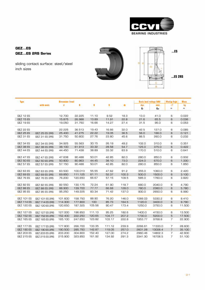
GEZ...ESGEZ...ES 2RS Series
sliding contact surface: steel/steelinch sizes
...ES
...ES 2RS
..
..
GEZ 12 ESGEZ 15 ESGEZ 19 ES
GEZ 22 ESGEZ 25 ESGEZ 31 ES
GEZ 34 ESGEZ 38 ESGEZ 44 ES
GEZ 47 ESGEZ 50 ESGEZ 57 ES
GEZ 63 ESGEZ 69 ESGEZ 76 ES
GEZ 82 ESGEZ 88 ESGEZ 95 ES
GEZ 101 ESGEZ 114 ESGEZ 120 ES
GEZ 127 ESGEZ 152 ESGEZ 165 ES
GEZ 177 ESGEZ 190 ESGEZ 203 ESGEZ 215 ES
GEZ 25 ES 2RSGEZ 31 ES 2RS
GEZ 34 ES 2RSGEZ 38 ES 2RSGEZ 44 ES 2RS
GEZ 47 ES 2RSGEZ 50 ES 2RSGEZ 57 ES 2RS
GEZ 63 ES 2RSGEZ 69 ES 2RSGEZ 76 ES 2RS
GEZ 82 ES 2RSGEZ 88 ES 2RSGEZ 95 ES 2RS
GEZ 101 ES 2RSGEZ 114 ES 2RSGEZ 120 ES 2RS
GEZ 127 ES 2RSGEZ 152 ES 2RSGEZ 165 ES 2RS
GEZ 177 ES 2RSGEZ 190 ES 2RSGEZ 203 ES 2RSGEZ 215 ES 2RS
9.5211.9114.27
16.6619.0523.80
26.1928.5833.32
42.8538.1042.85
47.6252.3757.15
61.9066.6871.42
76.2085.7390.47
95.25104.77103.17
111.12119.05127.00134.92
12.70015.87519.050
22.22525.40031.750
34.92538.10044.450
47.63850.80057.150
63.50069.85076.200
82.55088.90095.250
101.600114.300120.650
127.000152.400165.100
177.800190.500203.200215.900
22.22526.98831.750
36.51341.27550.800
55.56361.91371.438
90.48880.96390.488
100.013111.125120.650
130.175139.700149.225
158.750177.800187.325
196.850222.250247.650
266.700285.750304.800323.850
18.322.827.4
32.036.545.6
49.254.763.9
82.073.082.0
91.2100.3109.5
118.7128.0137.0
146.0164.5173.4
182.6207.2222.8
239.9257.0274.2291.3
13.021.631.5
42.556.086.5
102.0125.0170.0
280.0224.0280.0
355.0500.0585.0
680.0780.0900.0
1066.031120.01250.0
1400.01730.01953.77
2266.612601.282960.463341.30
41.065.595.0
127.0166.0260.0
310.0375.0510.0
850.0670.0850.0
1060.01500.01760.0
2040.02360.02650.0
5330.23400.03750.0
4150.05200.09768.8
11333.013006.414802.316706.5
666
666
666
666
666
666
666
657
7777
0.0220.0360.053
0.0850.1210.232
0.3510.4220.641
0.9321.3301.850
2.4203.1003.820
4.7905.7806.990
8.4109.79011.500
13.50017.50022.900
28.60035.10042.60051.100
11.1013.8916.66
19.4322.2227.76
30.1533.3238.89
50.0144.4550.01
55.5561.1166.67
72.2477.7783.34
88.90100
105.56
111.13120.65123.82
133.35142.87152.40161.92
Type Dimension (mm) ===== Basic load ratings (kN) Misalign Angle Mass with seals d D B C d2 dyn. stat. ===========� kg Cr Cor � �
o
22
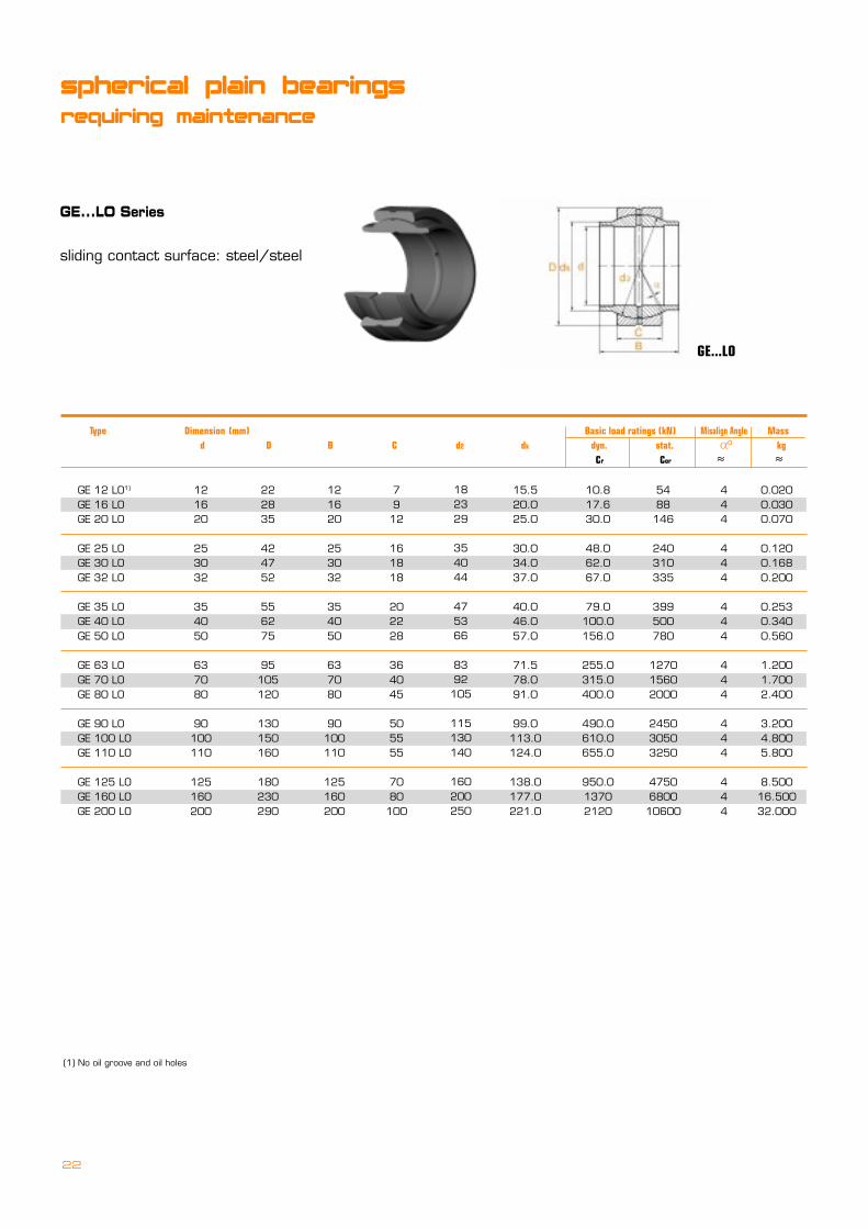
GE...LO Series
sliding contact surface: steel/steel
GE...LO
GE 12 LO1)
GE 16 LOGE 20 LO
GE 25 LOGE 30 LOGE 32 LO
GE 35 LOGE 40 LOGE 50 LO
GE 63 LOGE 70 LOGE 80 LO
GE 90 LOGE 100 LOGE 110 LO
GE 125 LOGE 160 LOGE 200 LO
7912
161818
202228
364045
505555
7080100
222835
424752
556275
95105120
130150160
180230290
121620
253032
354050
637080
90100110
125160200
15.520.025.0
30.034.037.0
40.046.057.0
71.578.091.0
99.0113.0124.0
138.0177.0221.0
10.817.630.0
48.062.067.0
79.0100.0156.0
255.0315.0400.0
490.0610.0655.0
950.013702120
5488146
240310335
399500780
127015602000
245030503250
4750680010600
444
444
444
444
444
444
0.0200.0300.070
0.1200.1680.200
0.2530.3400.560
1.2001.7002.400
3.2004.8005.800
8.50016.50032.000
182329
354044
475366
8392105
115130140
160200250
121620
253032
354050
637080
90100110
125160200
spherical plain bearings
requiring maintenance
(1) No oil groove and oil holes
== Type =Dimension (mm) ==================Basic load ratings (kN) Misalign Angle Mass d D B C d2 dk ========== dyn. stat. ===========� kg Cr Cor � �
o
23
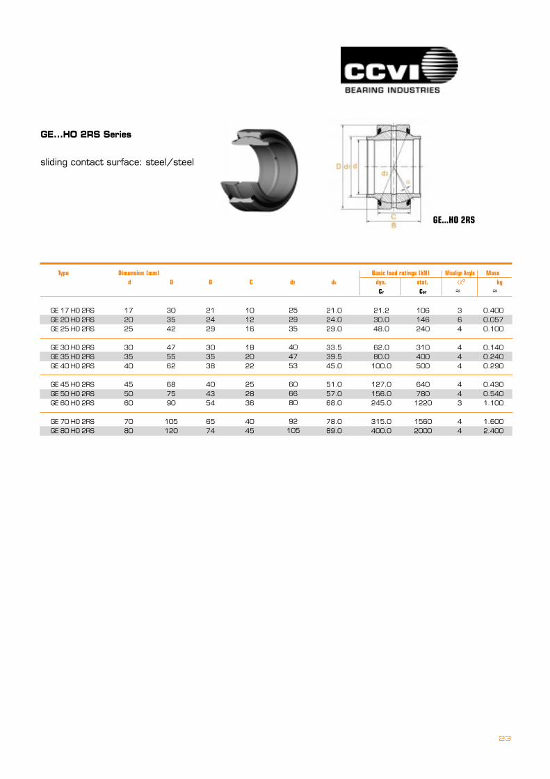
GE...HO 2RS
GE...HO 2RS Series
sliding contact surface: steel/steel
GE 17 HO 2RSGE 20 HO 2RSGE 25 HO 2RS
GE 30 HO 2RSGE 35 HO 2RSGE 40 HO 2RS
GE 45 HO 2RSGE 50 HO 2RSGE 60 HO 2RS
GE 70 HO 2RSGE 80 HO 2RS
101216
182022
252836
4045
303542
475562
687590
105120
212429
303538
404354
6574
21.024.029.0
33.539.545.0
51.057.068.0
78.089.0
21.230.048.0
62.080.0
100.0
127.0156.0245.0
315.0400.0
106146240
310400500
6407801220
15602000
364
444
443
44
0.4000.0570.100
0.1400.2400.290
0.4300.5401.100
1.6002.400
252935
404753
606680
92105
172025
303540
455060
7080
== Type =Dimension (mm) ==================Basic load ratings (kN) Misalign Angle Mass d D B C d2 dk ========== dyn. stat. ===========� kg Cr Cor � �
o
24
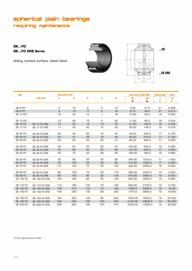
GE 6 FO1)
GE 8 FO1)
GE 10 FO1)
GE 12 FO1)
GE 15 FOGE 17 FO
GE 20 FOGE 25 FOGE 30 FO
GE 35 FOGE 40 FOGE 45 FO
GE 50 FOGE 60 FOGE 70 FO
GE 80 FOGE 90 FOGE 100 FO
GE 110 FOGE 120 FOGE 140 FO
GE 160 FOGE 180 FOGE 200 FO
GE 15 FO 2RSGE 17 FO 2RS
GE 20 FO 2RSGE 25 FO 2RSGE 30 FO 2RS
GE 35 FO 2RSGE 40 FO 2RSGE 45 FO 2RS
GE 50 FO 2RSGE 60 FO 2RSGE 70 FO 2RS
GE 80 FO 2RSGE 90 FO 2RSGE 100 FO 2RS
GE 110 FO 2RSGE 120 FO 2RSGE 140 FO 2RS
GE 160 FO 2RSGE 180 FO 2RSGE 200 FO 2RS
91112
151620
252832
354043
566370
758585
100115130
135155165
6810
121517
202530
354045
506070
8090100
110120140
160180200
161922
263035
424755
626875
90105120
130150160
180210230
260290320
131618
222529
354047
536066
8092105
115130140
160180200
225250275
5.508.1510.80
17.0021.2030.00
48.0062.0080.00
100.00127.00156.00
245.00315.00400.00
490.00610.00655.00
950.001080.01370.0
1530.002120.002320.00
27.540.554.0
85.0106.0146.0
240.0310.0400.0
500.0640.0780.0
1220.01560.02000.0
2450.03050.03250.0
4750.05400.06800.0
7650.010600.011600.0
212118
181619
171717
161715
171716
141514
121616
161415
0.0080.0140.020
0.0340.0460.078
0.1500.1900.290
0.3900.5200.680
1.4002.0002.900
3.5005.4005.900
9.70015.0018.500
25.00035.50045.000
567
91012
161820
222528
364045
505555
707080
80100100
GE...FOGE...FO 2RS Series
sliding contact surface: steel/steel
...FO
...FO 2RS
spherical plain bearings
requiring maintenance
(1) No oil groove and oil holes
Type Dimension (mm) =====Basic load ratings (kN) Misalign Angle Mass with seals d D B C d2 dyn. stat. ===========� kg Cr Cor � �
o
25
GE 6 UKGE 8 UKGE 10 UK
GE 12 UKGE 15 UKGE 17 UK
GE 20 UKGE 25 UKGE 30 UK
GE 17 UK 2RS(1)
GE 20 UK 2RS(1)
GE 25 UK 2RS(1)
GE 30 UK 2RS(1)
GE 35 UK 2RSGE 40 UK 2RSGE 45 UK 2RS
GE 50 UK 2RSGE 60 UK 2RSGE 70 UK 2RS
GE 80 UK 2RSGE 90 UK 2RSGE 100 UK 2RS
GE 110 UK 2RSGE 120 UK 2RSGE 140 UK 2RS
GE 160 UK 2RSGE 180 UK 2RSGE 200 UK 2RS
GE 220 UK 2RS(2)
GE 240 UK 2RS(2)
GE 260 UK 2RS(2)
456
7910
121618
202225
283640
455055
557070
8080
100
100100110
6810
121517
202530
354045
506070
8090100
110120140
160180200
220240260
141619
222630
354247
556268
7590
105
120130150
160180210
230260290
320340370
101316
182225
293540
475360
668092
105115130
140160180
200225250
275300325
131512
10810
976
677
666
657
667
867
887
0.0040.0070.011
0.0160.0250.038
0.0610.1100.140
0.2200.3000.400
0.5401.0001.500
2.2002.7004.300
4.7008.00011.000
13.50018.50028.000
35.50040.00050.000
689
101214
162022
252832
354449
556070
708590
105105130
135140150
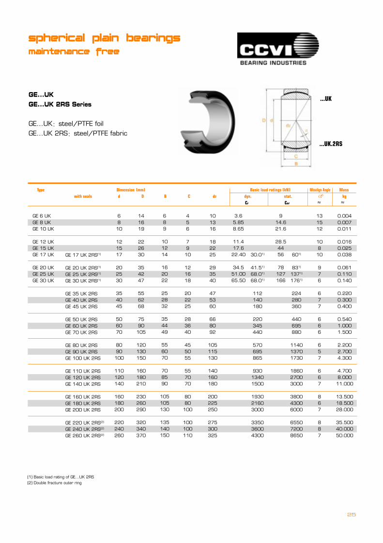
GE...UKGE...UK 2RS Series
GE...UK�steel/PTFE foilGE...UK 2RS�steel/PTFE fabric
...UK
...UK.2RS
(1) Basic load rating of GE...UK 2RS(2) Double fracture outer ring
30.01)
41.51)
68.01)
68.01)
112140180
220345440
570695865
93013401500
193021603000
335036004300
3.65.858.65
11.417.622.40
34.551.0065.50
601)
831)
1371)
1761)
224280360
440695880
114013701730
186027003000
380043006000
655072008650
914.621.6
28.54456
78127166
Type Dimension (mm) =Basic load ratings (kN) Misalign Angle Mass with seals d D B C d2 dyn. stat. =============� kg Cr Cor � �
o
spherical plain bearings
maintenance free
26
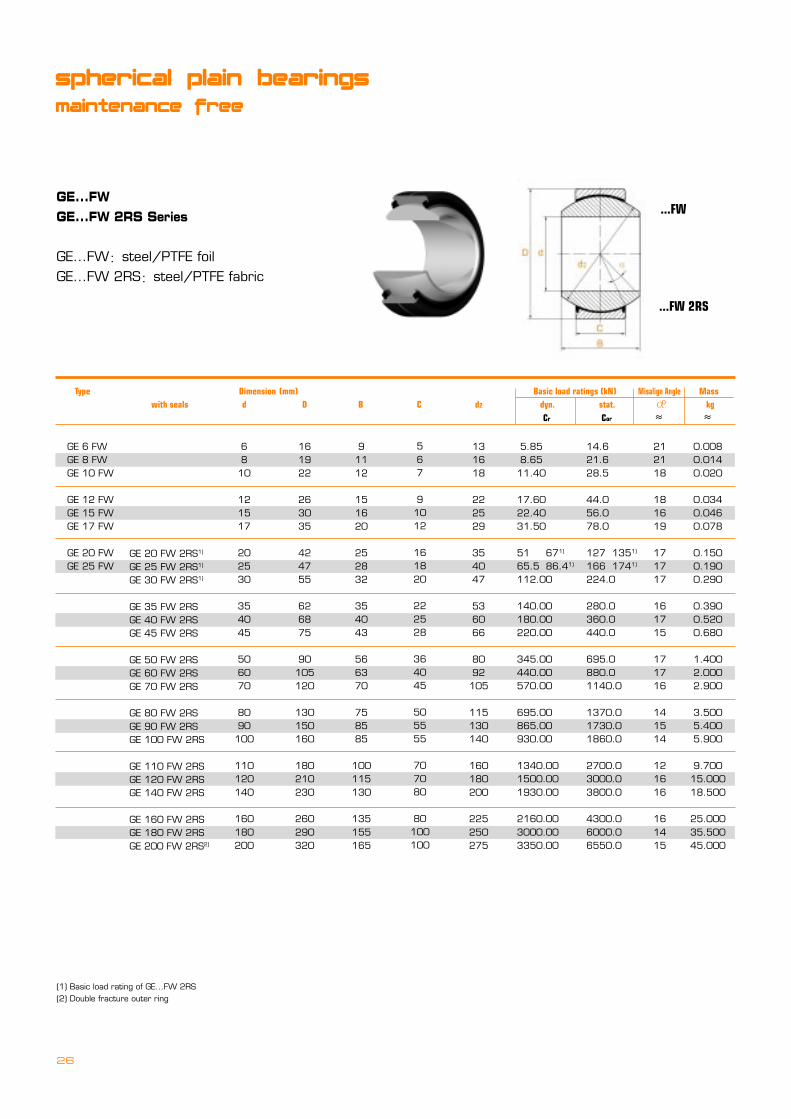
GE...FWGE...FW 2RS Series
GE...FW�steel/PTFE foilGE...FW 2RS�steel/PTFE fabric
...FW
...FW 2RS
Type Dimension (mm) =====Basic load ratings (kN) Misalign Angle Mass with seals d D B C d2 dyn. stat. ===========� kg Cr Cor � �
o
GE 6 FWGE 8 FWGE 10 FW
GE 12 FWGE 15 FWGE 17 FW
GE 20 FWGE 25 FW
GE 20 FW 2RS1)
GE 25 FW 2RS1)
GE 30 FW 2RS1)
GE 35 FW 2RSGE 40 FW 2RSGE 45 FW 2RS
GE 50 FW 2RSGE 60 FW 2RSGE 70 FW 2RS
GE 80 FW 2RSGE 90 FW 2RSGE 100 FW 2RS
GE 110 FW 2RSGE 120 FW 2RSGE 140 FW 2RS
GE 160 FW 2RSGE 180 FW 2RSGE 200 FW 2RS2)
91112
151620
252832
354043
566370
758585
100115130
135155165
6810
121517
202530
354045
506070
8090100
110120140
160180200
161922
263035
424755
626875
90105120
130150160
180210230
260290320
131618
222529
354047
536066
8092105
115130140
160180200
225250275
5.85 8.6511.40
17.6022.4031.50
51 671)
65.5 86.41)
112.00
140.00180.00220.00
345.00440.00570.00
695.00865.00930.00
1340.001500.001930.00
2160.003000.003350.00
14.621.628.5
44.056.078.0
127 1351)
166 1741)
224.0
280.0360.0440.0
695.0880.01140.0
1370.01730.01860.0
2700.03000.03800.0
4300.06000.06550.0
212118
181619
171717
161715
171716
141514
121616
161415
0.0080.0140.020
0.0340.0460.078
0.1500.1900.290
0.3900.5200.680
1.4002.0002.900
3.5005.4005.900
9.70015.00018.500
25.00035.50045.000
567
91012
161820
222528
364045
505555
707080
80100100
(1) Basic load rating of GE...FW 2RS(2) Double fracture outer ring
spherical plain bearings
maintenance free
27
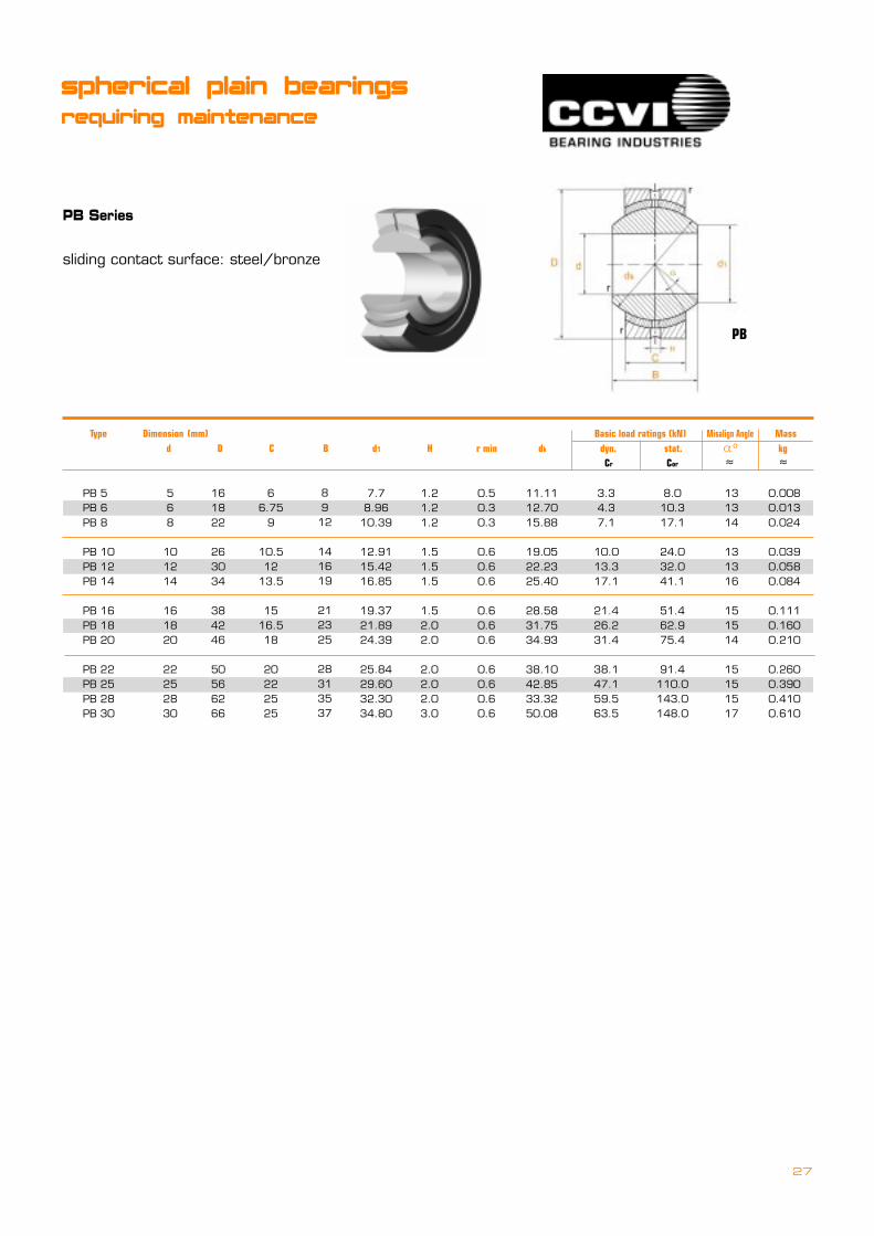
PB Series
sliding contact surface: steel/bronze
PB
PB 5PB 6PB 8
PB 10PB 12PB 14
PB 16PB 18PB 20
PB 22PB 25PB 28PB 30
66.75
9
10.512
13.5
1516.518
20222525
568
101214
161820
22252830
161822
263034
384246
50566266
7.78.96
10.39
12.9115.4216.85
19.3721.8924.39
25.8429.6032.3034.80
3.34.37.1
10.013.317.1
21.426.231.4
38.147.159.563.5
8.010.317.1
24.032.041.1
51.462.975.4
91.4110.0143.0148.0
131314
131316
151514
15151517
0.0080.0130.024
0.0390.0580.084
0.1110.1600.210
0.2600.3900.4100.610
8912
141619
212325
28313537
1.21.21.2
1.51.51.5
1.52.02.0
2.02.02.03.0
0.50.30.3
0.60.60.6
0.60.60.6
0.60.60.60.6
11.1112.7015.88
19.0522.2325.40
28.5831.7534.93
38.1042.8533.3250.08
= Type ===Dimension (mm) ======================Basic load ratings (kN) Misalign Angle Mass d D C B d1 H r min dk dyn. stat. =� kg Cr Cor � �
o
spherical plain bearings
requiring maintenance

28
GE...SX Series
sliding contact surface: steel/steel
GE...SX
GE 25 SXGE 28 SXGE 30 SX
GE 35 SXGE 40 SXGE 45 SX
GE 50 SXGE 55 SXGE 60 SX
GE 65 SXGE 70 SXGE 80 SX
GE 90 SXGE 100 SXGE 110 SX
GE 120 SXGE 130 SXGE 140 SX
GE 150 SXGE 160 SXGE 170 SX
GE 180 SXGE 190 SXGE 200 SX
141516
171819
192222
222427
303036
364242
454854
616166
475255
626875
809095
100110125
140150170
180200210
225240260
280290310
42.54750
566066
748086
92102115
130140160
170190200
213225250
260275290
112
21.51.5
445
5710
111215
172020
212127
212926
47.560.063.0
76.590.0106
118146160
173208250
320345475
510640680
780900
1,100
1,3201,3701,560
236300315
390450530
585735800
8651,0401,250
1,6001,7602,360
2,5503,2003,450
3,9004,5005,500
6,7006,9507,800
3.53.03.0
3.03.03.0
3.03.03.0
2.52.52.5
2.52.02.0
2.01.01.0
1.01.01.0
1.01.51.0
0.1480.1800.208
0.2680.3270.416
0.4550.6450.714
0.7591.0401.540
2.0902.3403.680
3.9705.9206.330
8.0109.42012.300
17.40018.20022.500
141516
171819
192222
222427
303036
364242
454854
616166
252830
354045
505560
657080
90100110
120130140
150160170
180190200
151617
181920
202323
232529
323238
384545
485157
646470
angular contact
spherical plain bearings
requiring maintenance
= Type ===Dimension (mm) ======================Basic load ratings (kN) Misalign Angle Mass d D T dk B C S dyn. stat. =� kg Cr Cor � �
o
29
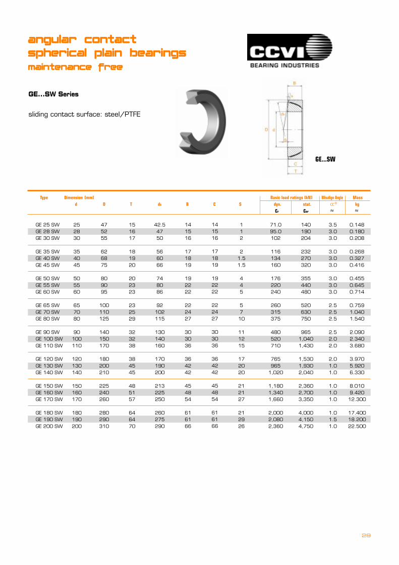
GE...SW Series
sliding contact surface: steel/PTFE
GE...SW
GE 25 SWGE 28 SWGE 30 SW
GE 35 SWGE 40 SWGE 45 SW
GE 50 SWGE 55 SWGE 60 SW
GE 65 SWGE 70 SWGE 80 SW
GE 90 SWGE 100 SWGE 110 SW
GE 120 SWGE 130 SWGE 140 SW
GE 150 SWGE 160 SWGE 170 SW
GE 180 SWGE 190 SWGE 200 SW
141516
171819
192222
222427
303036
364242
454854
616166
475255
626875
809095
100110125
140150170
180200210
225240260
280290310
42.54750
566066
748086
92102115
130140160
170190200
213225250
260275290
112
21.51.5
445
5710
111215
172020
212127
212926
71.095.0102
116134160
176220240
260315375
480520710
765965
1,020
1,1801,3401,660
2,0002,0802,360
140190204
232270320
355440480
520630750
9651,0401,430
1,5301,9302,040
2,3602,7003,350
4,0004,1504,750
3.53.03.0
3.03.03.0
3.03.03.0
2.52.52.5
2.52.02.0
2.01.01.0
1.01.01.0
1.01.51.0
0.1480.1800.208
0.2680.3270.416
0.4550.6450.714
0.7591.0401.540
2.0902.3403.680
3.9705.9206.330
8.0109.42012.300
17.40018.20022.500
141516
171819
192222
222427
303036
364242
454854
616166
252830
354045
505560
657080
90100110
120130140
150160170
180190200
151617
181920
202323
232529
323238
384545
485157
646470
= Type ===Dimension (mm) ======================Basic load ratings (kN) Misalign Angle Mass d D T dk B C S dyn. stat. =� kg Cr Cor � �
o
angular contact
spherical plain bearings
maintenance free

30
COM
COM Series
sliding contact surface: steel/steel
spherical plain bearings
requiring maintenance
= Type ===Dimension (mm) =========================Basic load ratings (kN) Misalign Angle ==== Mass d D C B d1 M dk stat.==========�==========kg REF Cor � �
o
COM 3COM 4COM 5
COM 6COM 7COM 8
COM 9COM 10COM 12
COM 14COM 16
4.8266.3507.938
9.52511.11312.700
14.28815.87519.050
22.22525.400
14.28816.66719.050
20.63723.01725.400
27.78030.16336.513
39.68844.450
7.148.719.53
10.3111.1012.70
14.2715.8819.05
22.2225.40
14.522.028.8
37.442.0558.9
74.094.7142.0
186.7245.6
0.0060.0100.014
0.0170.0210.029
0.0390.0500.093
0.1190.175
5.546.357.14
7.928.719.91
11.1012.7015.06
17.8620.24
7.449.24
10.62
13.0913.4615.24
17.0518.7723.36
24.8328.40
0.380.560.80
0.800.800.80
0.800.801.10
1.101.10
10.3112.7014.27
16.6617.4519.84
22.2324.5930.15
33.3238.10
1113.512
108
9.5
9.58.59
9.510
31
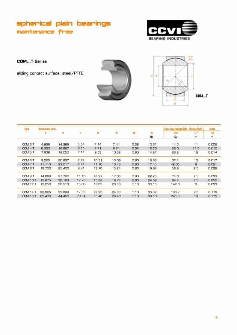
COM...T Series
sliding contact surface: steel/PTFE
COM...T
COM 3 TCOM 4 TCOM 5 T
COM 6 TCOM 7 TCOM 8 T
COM 9 TCOM 10 TCOM 12 T
COM 14 TCOM 16 T
4.8266.3507.938
9.52511.11312.700
14.28815.87519.050
22.22525.400
14.28816.66719.050
20.63723.01725.400
27.78030.16336.513
39.68844.450
7.148.719.53
10.3111.1012.70
14.2715.8819.05
22.2325.40
14.522.028.8
37.442.0558.9
74.094.7142.0
186.7245.6
0.0060.0100.014
0.0170.0210.029
0.0390.0500.093
0.1190.175
5.546.357.14
7.928.719.91
11.1012.7015.06
17.8620.24
7.449.2410.62
13.0913.4615.24
17.0518.7723.36
24.8328.40
0.380.560.80
0.800.800.80
0.800.801.10
1.101.10
10.3112.7014.27
16.6617.4519.84
22.2324.5930.15
33.3238.10
1113.512
108
9.5
9.58.59
9.510
spherical plain bearings
maintenance free
= Type ===Dimension (mm) =========================Basic load ratings (kN) Misalign Angle ==== Mass d D C B d1 M dk stat.==========�==========kg REF Cor � �
o

32
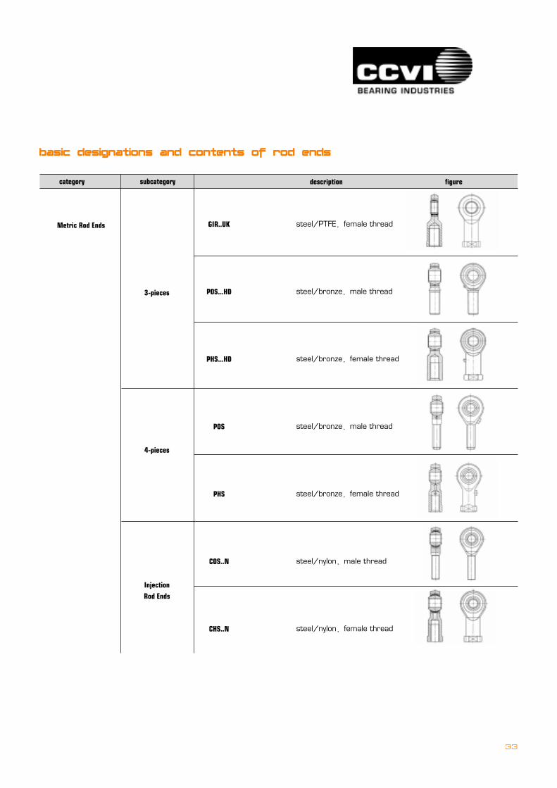
Metric Rod Ends
2-pieces
3-pieces
steel/PTFE�male thread
steel/PTFE�female thread
steel/PTFE�male thread
steel/PTFE�female thread
steel/steel�male thread
steel/steel�female thread
steel/PTFE�male thread
KMDV
KFDV
COS
CHS
GAR..DO
GIR..DO
GAR..UK
subcategory description figurecategory
basic designations and contents of rod ends
engineering data
33
Metric Rod Ends
3-pieces
4-pieces
Injection
Rod Ends
steel/PTFE�female thread
steel/bronze�male thread
steel/bronze�female thread
steel/bronze�male thread
steel/bronze�female thread
steel/nylon�male thread
steel/nylon�female thread
GIR..UK
POS...HD
PHS...HD
POS
PHS
COS..N
CHS..N
subcategory description figurecategory
basic designations and contents of rod ends
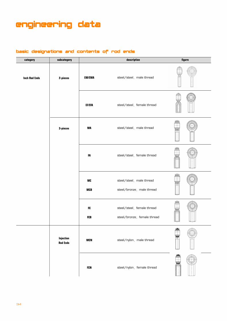
Inch Rod Ends 2-pieces
3-pieces
Injection
Rod Ends
steel/steel�male thread
steel/steel�female thread
steel/steel�male thread
steel/steel�female thread
steel/steel�male thread
steel/bronze�male thread
steel/steel�female thread
steel/bronze�female thread
steel/nylon�male thread
steel/nylon�female thread
EM/EMA
EF/EFA
MA
FA
MC
MCB
FC
FCB
MCN
FCN
basic designations and contents of rod ends
engineering data
subcategory description figurecategory
34

� Radial Load RatingTypically, rod end strength is measured in two dimensions: radially, or strength vertically when the rod end is in a �standup� position, andaxially, or along the axis of an imagined pin through the bore of the rod end�s spherical ball.
�==Ultimate Static Radial LoadUltimate Static Radial Load is calculated in pounds (or Newton) of force, is that force which when gradually applied in radial direction tothe stationery rod ends, results in fracture or catastrophic failure.
�==Static Radial loadStatic Radial Load is that force which, when applied in a manner similar to that above, results in distension of one or more of the rod endcomponents, which effectively renders the rod end as non-functional.
CCVI references the Static Load in this catalog, which generally includes a safety factor of at least 10%.
Note that the load ratings listed assume standard metal-to-metal sliding surface configurations, except where PTFE liners are noted as�standard�. Optional grease fittings, PTFE liners, and even customer mounted components can affect the integrity and strength of the rodend components.
� Axial Load RatingThe axial load is measured by applying a force along the axis of a real or imagined pin through the center of the spherical ball�s bore.In general terms, and depending on material and other variables, the axial rating is generally 10-20% of the ultimate static load rating.Because a complete 100% axial load contradicts the purpose of a rod end�s misalignment design, axial load is generally considered forreference only. Given the breadth of applications in which a rod end can be placed. CCVI recommends that the load ratings supplied hereinbe used for reference only, and that the user assure that the load limits not be exceeded.
35
Fig. 11
radial load axial load

36
engineering data
� Allowed load for rod end
Pperm=COb2b6
in which: Pperm max allowed load for spherical plain bearings rod end, N
C0 static equivalent load, N
b2 temperature factor
for lubricated spherical plain bearings rod end, choose from table 23
for maintenance-free spherical plain bearings rod endW
steel/copper sliding contact surface, see Fig 12
steel/PTFE paint cloth sliding contact surface, see Fig 13
steel/PTFE fiber cloth sliding contact surface, see Fig 14
b6 load type factor, see Fig 15
calculation
working condition temperature factor
over to b2
-
120
160
120
160
180
1,0
0,9
0,8
Table.23
Fig. 13
Fig. 12
Fig. 14
note: values in the brackets apply to spherical plain bearings rod end with lubricating hole or nozzle.
Fig. 15
constant load
b6 = 1
one direction pulse load
b6 = 0.5(0.35)
changing load
b6 = 0.5(0.35)
+Fr
+Fr
+Fr
- Fr
37
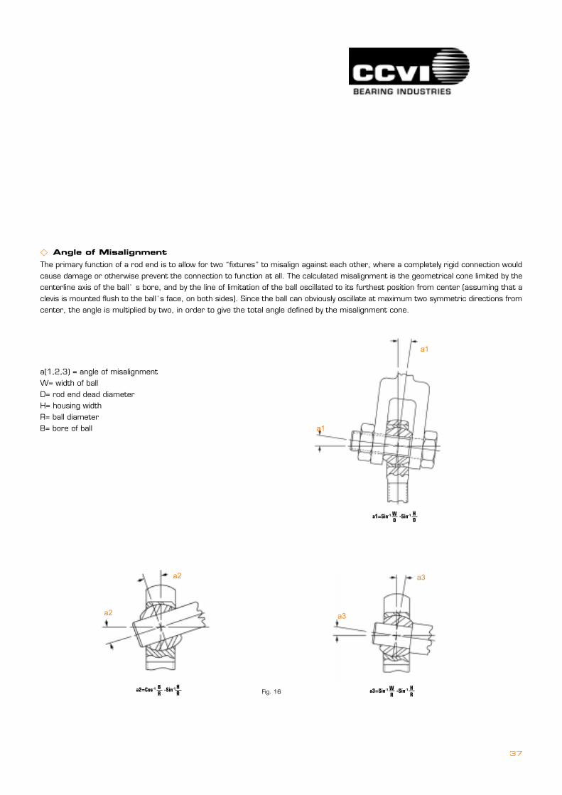
� Angle of MisalignmentThe primary function of a rod end is to allow for two �fixtures� to misalign against each other, where a completely rigid connection wouldcause damage or otherwise prevent the connection to function at all. The calculated misalignment is the geometrical cone limited by thecenterline axis of the ball�s bore, and by the line of limitation of the ball oscillated to its furthest position from center (assuming that aclevis is mounted flush to the ball�s face, on both sides). Since the ball can obviously oscillate at maximum two symmetric directions fromcenter, the angle is multiplied by two, in order to give the total angle defined by the misalignment cone.
a(1,2,3) = angle of misalignmentW= width of ballD= rod end dead diameterH= housing widthR= ball diameterB= bore of ball
a1
a1
a1=Sin-1 -Sin-1WD
HD
a3
a3
a2
a2
a2=Cos-1 -Sin-1BR
HR a3=Sin-1 -Sin-1W
RHRFig. 16
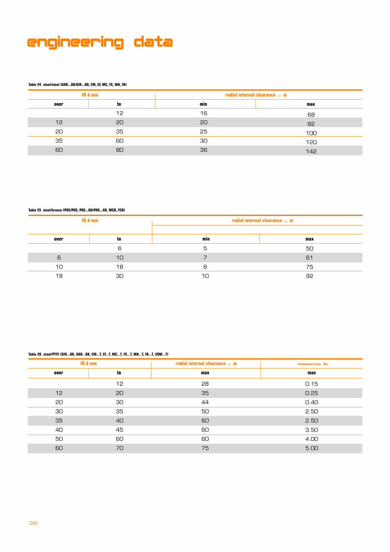
38
ID d mm radial internal clearance � m
over to min max
12
20
35
60
12
20
35
60
80
16
20
25
30
36
Table 24 steel/steel (GAR...DO/GIR...DO, EM, EF, MC, FC, MA, FA)
68
82
100
120
142
ID d mm radial internal clearance � m
over to min max
6
10
18
6
10
18
30
5
7
8
10
Table 25 steel/bronze (POS/PHS, POS...HD/PHS...HD, MCB, FCB)
50
61
75
92
ID d mm radial internal clearance � m breakaway torque Nm
over to max max
12
20
30
35
40
50
60
12
20
30
35
40
45
60
70
28
35
44
50
60
60
60
75
Table 26 steel/PTFE (GIR...UK, GAR...UK, EM...T, EF...T, MC...T, FC...T, MA...T, FA...T, COM...T)
0.15
0.25
0.40
2.50
2.50
3.50
4.00
5.00
engineering data

39
Generally, CCVI recommend to match the male and female thread with same accuracy if application required, it is better to match the
female thread with higher accuracy male thread.
For example, match 3A male thread with 2B female thread.
� Accessories
�==Stud
L
N
S
P
Standard studs are carbon steel, zinc plated withyellow dichromate for corrosion resistance unlessspecified otherwise
� D
L
� D1
� D2
L1
ao
Rod End L P S N
Bore Size REF 030 Min Thread Length Thread Size
UNF-2A
3/16�
1/4�
5/16�
3/8�
7/16�
1/2�
5/8�
3/4�
1.000
1.031
1.219
1.562
1.750
2.000
2.500
3.000
.500
.562
.687
.906
1.062
1.125
1.500
1.812
.437
.500
.593
.812
.937
1.000
1.375
1.625
10-32
1/4-28
5/16-24
3/8-24
7/16-20
1/2-20
5/8-18
3/4-16
Table 27
Type =======� Dmm ===� D1mm ===� D2mm ===L1 mm =====Lmm ao
BN3.00
BN4.00
4
5
Table 28 Metric Zerk
3.2
4.2
3
4
2
2.5
4.6
5.5
90
90
�==Grease fitting
.260DIA.
.310
.260DIA.Ref.
.350
Ref.
Standard Drive Fit Zerk Standard Thread Zerk Standard grease fitting place ments
rod ends
metric sizes, maintenance free
40
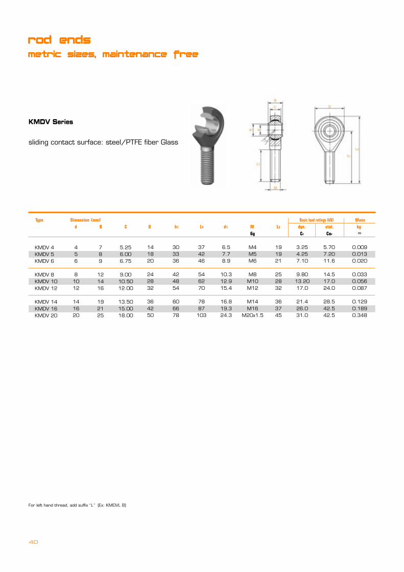
For left hand thread, add suffix�L� (Ex: KMDVL 8)
KMDV Series
sliding contact surface: steel/PTFE fiber Glass
KMDV 4KMDV 5KMDV 6
KMDV 8KMDV 10KMDV 12
KMDV 14KMDV 16KMDV 20
Type === Dimension (mm) Basic load ratings (kN) Mass d B C D h1 L4 d1 M L3 dyn. stat. kg 6g Cr Cor �
456
81012
141620
789
121416
192125
5.256.006.75
9.0010.5012.00
13.5015.0018.00
141820
242832
364250
303336
424854
606678
374246
546270
7887103
M4M5M6
M8M10M12
M14M16
M20x1.5
3.254.257.10
9.8013.2017.0
21.426.031.0
5.707.2011.6
14.517.024.0
28.542.542.5
0.0090.0130.020
0.0330.0560.087
0.1290.1890.348
6.57.78.9
10.312.915.4
16.819.324.3
191921
252832
363745

41
KFDVKFDV...-1 Series
sliding contact surface: steel/PTFE fiber Glass
For left hand thread, add suffix�L� (Ex: KFDVL 8 / KFDVL 8-1)
KFDV 4KFDV 5KFDV 6
KFDV 8KFDV 10KFDV 12
KFDV 14KFDV 16KFDV 20
Type === Dimension (mm) Basic load ratings (kN) Mass Cetop d B C D h1 L4 d5 d4 d1 W M L3 dyn. stat. kg M 6H Cr Cor � Type 6H
456
81012
141620
789
121416
192125
5.256.006.75
9.0010.5012.00
13.5015.0018.00
141820
242832
364250
242730
364350
576477
313640
485766
7585102
9.511.013.0
16.019.022.0
27.029.037.0
7.89.0
10.0
12.515.017.5
20.022.027.5
6.57.78.9
10.312.915.4
16.819.324.3
8911
131719
222232
121012
162022
252833
M4M5M6
M8M10M12
M14M16
M20x1.5
3.254.257.10
9.8013.2017.0
21.426.031.0
5.707.2011.6
14.517.024.0
28.542.542.5
0.0110.0180.027
0.0460.0760.115
0.1700.2300.415
KFDV 4-1KFDV 5-1KFDV 6-1
KFDV 8-1KFDV 10-1KFDV 12-1
KFDV 14-1KFDV 16-1KFDV 20-1
M4M4M6
M8M10x1.25M12x1.25
M14M16x1.5M20x1.5

42
rod ends
metric sizes, maintenance free
COSSCOS stainless Series
sliding contact surface: steel/PTFE Foil
For left hand thread, add suffix�L� (Ex: COSL 8 /SCOSL 8)
COS 5COS 6COS 8
COS 10COS 12COS 14
COS 16COS 18COS 20
COS 22COS 25COS 28COS 30
Type === Dimension (mm) Basic load ratings (kN) Angle Mass d B C d1 D h1 L4 L3 M dyn. stat. � kg max max min 6g Cr Cor � �
o
568
101214
161820
22252830
8912
141619
212325
28313537
66.75
9
10.512
13.5
1516.518
20222425
7.78.910.3
12.915.416.8
19.321.824.3
25.829.5
32.2934.8
182024
283236
424650
54606670
333642
485460
667278
8494
103110
424654
627078
8795
103
111124136145
192125
283236
374145
48556266
M5M6M8
M10M12M14
M16M18x1.5M20x1.5
M22x1.5M24x2M27x2M30x2
67.6512.9
182431
3947.557
6885
102.88114
5.027.1813.04
18.520.832
45.246.945.6
61.172.878.695.9
131314
131316
151514
15151517
0.0130.0200.038
0.0550.0850.140
0.2100.2800.380
0.4800.6400.9491.100
43
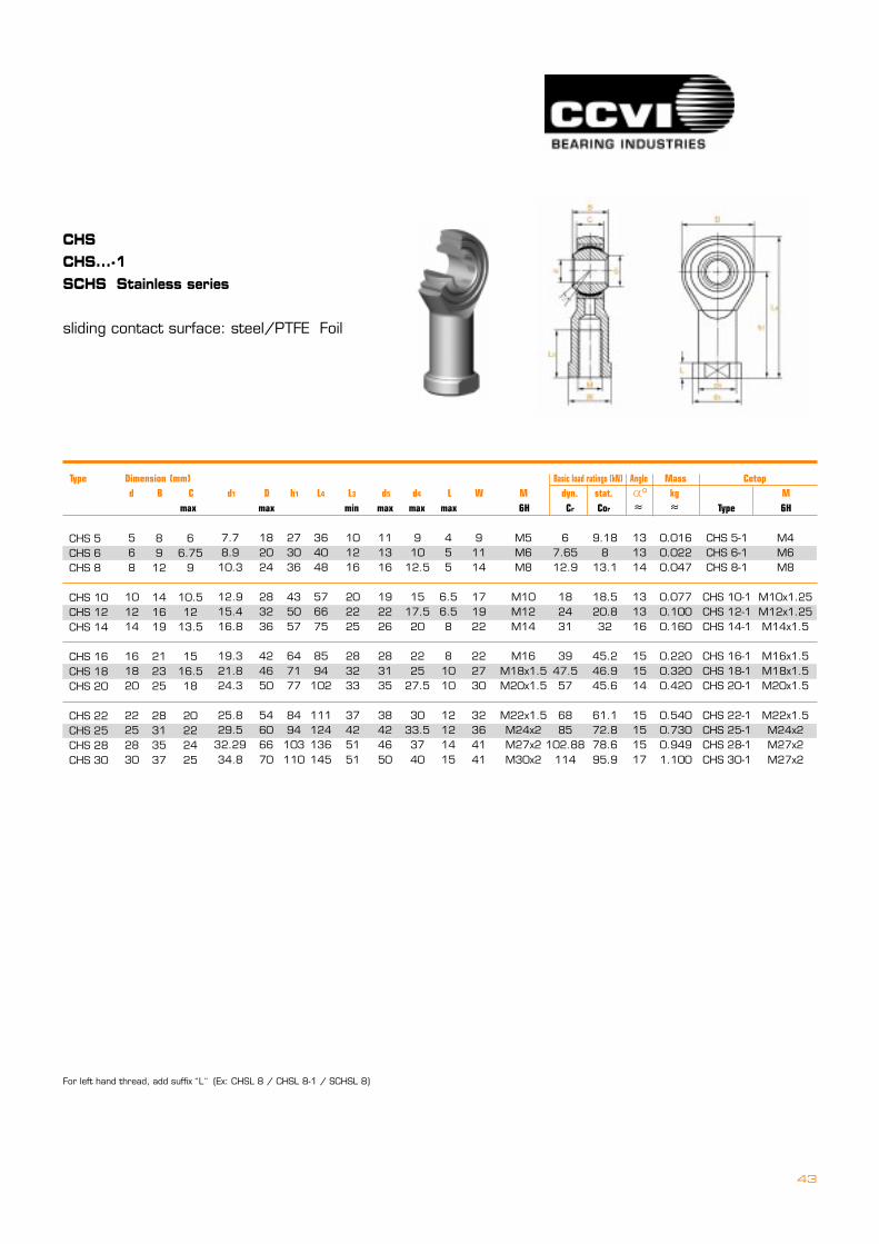
CHSCHS...-1SCHS Stainless series
sliding contact surface: steel/PTFE Foil
For left hand thread, add suffix�L� (Ex: CHSL 8 / CHSL 8-1 / SCHSL 8)
CHS 5CHS 6CHS 8
CHS 10CHS 12CHS 14
CHS 16CHS 18CHS 20
CHS 22CHS 25CHS 28CHS 30
Type === Dimension (mm) Basic load ratings (kN) Angle Mass Cetop d B C d1 D h1 L4 L3 d5 d4 L W M dyn. stat. � kg M max max min max max max 6H Cr Cor � � Type 6H
568
101214
161820
22252830
8912
141619
212325
28313537
66.75
9
10.512
13.5
1516.518
20222425
7.78.910.3
12.915.416.8
19.321.824.3
25.829.5
32.2934.8
182024
283236
424650
54606670
273036
435057
647177
8494103110
364048
576675
8594
102
111124136145
101216
202225
283233
37425151
111316
192226
283135
38424650
910
12.5
1517.520
2225
27.5
3033.53740
M5M6M8
M10M12M14
M16M18x1.5M20x1.5
M22x1.5M24x2M27x2M30x2
91114
171922
222730
32364141
67.6512.9
182431
3947.557
6885
102.88114
9.188
13.1
18.520.832
45.246.945.6
61.172.878.695.9
0.0160.0220.047
0.0770.1000.160
0.2200.3200.420
0.5400.7300.9491.100
CHS 5-1CHS 6-1CHS 8-1
CHS 10-1CHS 12-1CHS 14-1
CHS 16-1CHS 18-1CHS 20-1
CHS 22-1CHS 25-1CHS 28-1CHS 30-1
M4M6M8
M10x1.25M12x1.25M14x1.5
M16x1.5M18x1.5M20x1.5
M22x1.5M24x2M27x2M27x2
o
455
6.56.58
81010
12121415
131314
131316
151514
15151517
44
rod ends
metric sizes, requiring maintenance
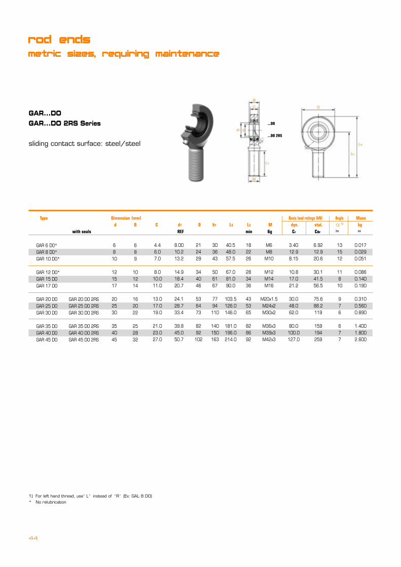
GAR...DOGAR...DO 2RS Series
sliding contact surface: steel/steel
1) For left hand thread, use�L� instead of �R� (Ex: GAL 8 DO)* No relubrication
...DO
...DO 2RS
GAR 6 DO*GAR 8 DO*GAR 10 DO*
GAR 12 DO*GAR 15 DOGAR 17 DO
GAR 20 DOGAR 25 DOGAR 30 DO
GAR 35 DOGAR 40 DOGAR 45 DO
Type === Dimension (mm) Basic load ratings (kN) Angle Mass d B C d1 D h1 L4 L3 M dyn. stat. � kg with seals REF min 6g Cr Cor � �
o
6810
121517
202530
354045
689
101214
162022
252832
4.46.07.0
8.010.011.0
13.017.019.0
21.023.027.0
8.0010.213.2
14.918.420.7
24.128.733.4
39.845.050.7
212429
344046
536473
8292102
303643
506167
7794110
140150163
40.548.057.5
67.081.090.0
103.5126.0146.0
181.0196.0214.0
182226
283436
435365
828692
M6M8M10
M12M14M16
M20x1.5M24x2M30x2
M36x3M39x3M42x3
3.4012.98.15
10.817.021.2
30.048.062.0
80.0100.0127.0
6.9212.920.6
30.141.556.5
75.688.2119
159194259
0.0170.0290.051
0.0860.1400.190
0.3100.5600.890
1.4001.8002.600
131512
118
10
976
677
GAR 20 DO 2RSGAR 25 DO 2RSGAR 30 DO 2RS
GAR 35 DO 2RSGAR 40 DO 2RSGAR 45 DO 2RS
45
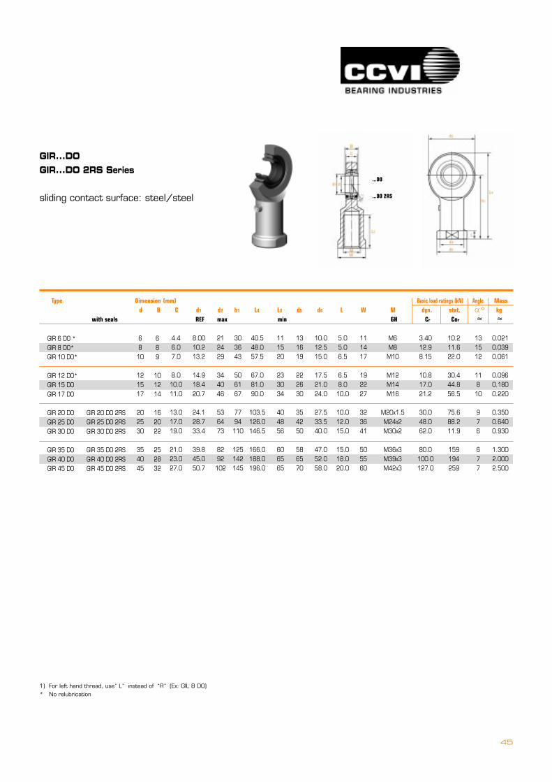
GIR...DOGIR...DO 2RS Series
sliding contact surface: steel/steel
1) For left hand thread, use�L� instead of �R� (Ex: GIL 8 DO)* No relubrication
...DO
...DO 2RS
GIR 6 DO *GIR 8 DO*GIR 10 DO*
GIR 12 DO*GIR 15 DOGIR 17 DO
GIR 20 DOGIR 25 DOGIR 30 DO
GIR 35 DOGIR 40 DOGIR 45 DO
Type === Dimension (mm) Basic load ratings (kN) Angle Mass d B C d1 d2 h1 L4 L3 d5 d4 L W M dyn. stat. � kg with seals REF max min 6H Cr Cor � �
o
6810
121517
202530
354045
689
101214
162022
252832
4.46.07.0
8.010.011.0
13.017.019.0
21.023.027.0
8.0010.213.2
14.918.420.7
24.128.733.4
39.845.050.7
212429
344046
536473
8292102
303643
506167
7794110
125142145
40.548.057.5
67.081.090.0
103.5126.0146.5
166.0188.0196.0
111520
233034
404856
606565
131619
222630
354250
586570
10.012.515.0
17.521.024.0
27.533.540.0
47.052.058.0
5.05.06.5
6.58.0
10.0
10.012.015.0
15.018.020.0
111417
192227
323641
505560
M6M8M10
M12M14M16
M20x1.5M24x2M30x2
M36x3M39x3M42x3
3.4012.98.15
10.817.021.2
30.048.062.0
80.0100.0127.0
10.211.622.0
30.444.856.5
75.688.211.9
159194259
0.0210.0390.061
0.0960.1800.220
0.3500.6400.930
1.3002.0002.500
131512
11810
976
677
GIR 20 DO 2RSGIR 25 DO 2RSGIR 30 DO 2RS
GIR 35 DO 2RSGIR 40 DO 2RSGIR 45 DO 2RS
46
rod ends
metric sizes, maintenance free
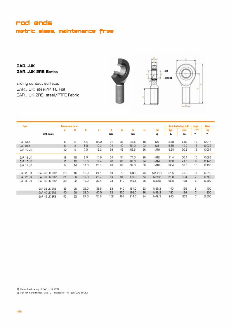
GAR...UKGAR...UK 2RS Series
sliding contact surface:GAR...UK: steel/PTFE FoilGAR...UK 2RS: steel/PTFE Fabric
1) Basic load rating of GAR...UK 2RS2) For left hand thread, use�L� instead of �R� (Ex: GAL 8 UK)
...UK
...UK 2RS
GAR 6 UKGAR 8 UKGAR 10 UK
GAR 12 UKGAR 15 UKGAR 17 UK
GAR 20 UKGAR 25 UKGAR 30 UK
Type === Dimension (mm) Basic load ratings (kN) Angle Mass d B C d1 D h1 L4 L3 M dyn. stat. � kg with seals max min 6g Cr Cor � �
o
6810
121517
202530
354045
689
101214
162022
252832
4.46.07.0
8.010.011.0
13.017.019.0
22.023.027.0
8.0010.213.2
14.918.420.7
24.128.733.4
39.845.050.8
212429
344046
536473
8292102
364248
546369
7894110
140150163
46.554.062.5
71.083.092.0
104.5126.0146.5
181.0196.0214.0
182226
283436
435365
828694
M6M8M10
M12M14M16
M20x1.5M24x2M30x2
M36x3M39x3M42x3
3.605.858.65
11.417.622.4
31.551.066.5
140185240
6.9212.920.6
30.141.556.5
75.6104138
159194259
0.0170.0290.051
0.0860.1400.190
0.3100.5600.890
1.4001.8002.600
131512
108
10
976
677
GAR 20 UK 2RS1)
GAR 25 UK 2RS1)
GAR 30 UK 2RS1)
GAR 35 UK 2RSGAR 40 UK 2RSGAR 45 UK 2RS
47
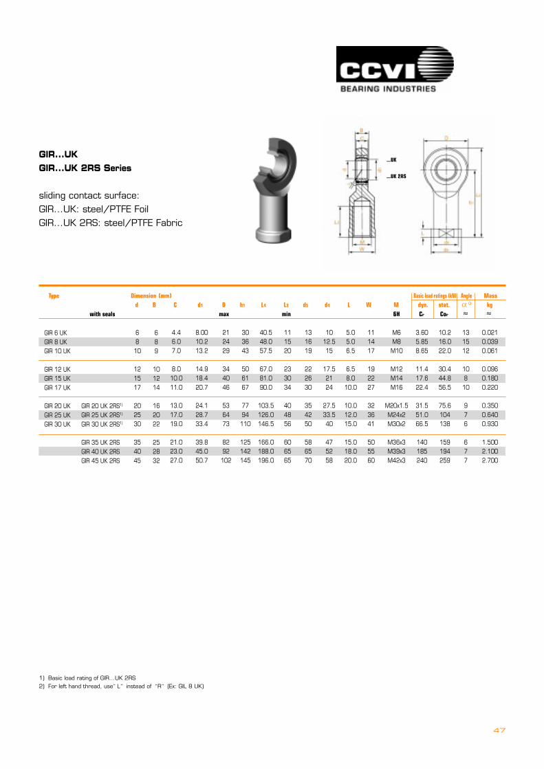
GIR...UKGIR...UK 2RS Series
sliding contact surface:GIR...UK: steel/PTFE FoilGIR...UK 2RS: steel/PTFE Fabric
1) Basic load rating of GIR...UK 2RS2) For left hand thread, use�L� instead of �R� (Ex: GIL 8 UK)
...UK
...UK 2RS
GIR 6 UKGIR 8 UKGIR 10 UK
GIR 12 UKGIR 15 UKGIR 17 UK
GIR 20 UKGIR 25 UKGIR 30 UK
Type === Dimension (mm) Basic load ratings (kN) Angle Mass d B C d1 D h1 L4 L3 d5 d4 L W M dyn. stat. � kg with seals max min 6H Cr Cor � �
o
6810
121517
202530
354045
689
101214
162022
252832
4.46.07.0
8.010.011.0
13.017.019.0
21.023.027.0
8.0010.213.2
14.918.420.7
24.128.733.4
39.845.050.7
212429
344046
536473
8292102
303643
506167
7794110
125142145
40.548.057.5
67.081.090.0
103.5126.0146.5
166.0188.0196.0
111520
233034
404856
606565
131619
222630
354250
586570
1012.515
17.52124
27.533.540
475258
5.05.06.5
6.58.010.0
10.012.015.0
15.018.020.0
111417
192227
323641
505560
M6M8M10
M12M14M16
M20x1.5M24x2M30x2
M36x3M39x3M42x3
3.605.858.65
11.417.622.4
31.551.066.5
140185240
10.216.022.0
30.444.856.5
75.6104138
159194259
0.0210.0390.061
0.0960.1800.220
0.3500.6400.930
1.5002.1002.700
131512
10810
976
677
GIR 20 UK 2RS1)
GIR 25 UK 2RS1)
GIR 30 UK 2RS1)
GIR 35 UK 2RSGIR 40 UK 2RSGIR 45 UK 2RS

48
rod ends
metric sizes, requiring maintenance
POS...HDSPOS...HD stainless Series
sliding contact surface: steel/bronze
POS 5 HDPOS 6 HDPOS 8 HD
POS 10 HDPOS 12 HDPOS 14 HD
POS 16 HDPOS 18 HDPOS 20 HD
POS 22 HDPOS 25 HDPOS 28 HDPOS 30 HD
Type === Dimension (mm) Basic load ratings (kN) Angle Mass d B C d1 D h1 L4 L3 dk M dyn. stat. � kg max max min REF 6g Cr Cor � �
o
568
101214
161820
22252830
8912
141619
212325
28313537
66.75
9
10.512
13.5
1516.518
20222425
7.78.910.3
12.915.416.8
19.321.824.3
25.829.532.2934.8
182024
283236
424650
54606670
333642
485460
667278
8494103110
424654
627078
8795103
111124136145
192125
283236
374145
48556266
11.1112.7015.88
19.0522.2325.40
28.5531.7534.93
38.1042.8647.6350.80
M5M6M8
M10M12M14
M16M18x1.5M20x1.5
M22x1.5M24x2M27x2M30x2
3.254.37.2
1013.417
21.626
31.5
3847.557.16
64
5.027.1813.04
18.520.832
45.246.945.6
64.172.878.695.9
131314
131316
151514
15151517
0.0130.0200.038
0.0550.0850.140
0.2100.2800.380
0.4800.6400.9491.100
For left hand thread, add suffix�L� (Ex: P0SL 8 HD / SPOSL 8 HD)

49
PHS...HDPHS...-1HDSPHS...HD stainless Series
sliding contact surface: steel/bronze
PHS 5 HDPHS 6 HDPHS 8 HD
PHS 10 HDPHS 12 HDPHS 14 HD
PHS 16 HDPHS 18 HDPHS 20 HD
PHS 22 HDPHS 25 HDPHS 28 HDPHS 30 HD
Type === Dimension (mm) Basic load ratings (kN) Angle Mass Cetop d B C d1 D h1 L4 L3 d5 d4 L W dk M dyn. stat. � kg M max max min max REF 6H Cr Cor � � Type 6H
o
568
101214
161820
22252830
89
12
141619
212325
28313537
66.75
9
10.512
13.5
1516.518
20222425
7.78.910.3
12.915.416.8
19.321.824.3
25.829.532.2934.8
182024
283236
424650
54606670
273036
435057
647177
8494103110
364048
576675
8594102
111124136145
101216
202225
283233
37425151
111316
192226
283135
38424650
910
12.5
1517.520
2225
27.5
3033.53740
455
6.56.58
81010
12121415
91114
171922
222730
32364141
11.1112.7015.88
19.0522.2325.40
28.5531.7534.93
38.1042.8647.6350.80
M5M6M8
M10M12M14
M16M18x1.5M20x1.5
M22x1.5M24x2M27x2M30x2
3.254.37.2
10.013.417.0
21.626.031.5
38.047.5
57.1664.0
9.188
13.1
18.520.832
45.246.945.6
61.172.878.695.8
0.0160.0220.047
0.0770.1000.160
0.2200.3200.420
0.5400.7300.9491.100
PHS 5-1 HDPHS 6-1 HDPHS 8-1 HD
PHS 10-1 HDPHS 12-1 HDPHS 14-1 HD
PHS 16-1 HDPHS 18-1 HDPHS 20-1 HD
PHS 22-1 HDPHS 25-1 HDPHS 28-1 HDPHS 30-1 HD
M4M6M8
M10x1.25M12x1.25
M14
M16x1.5M18x1.5M20x1.5
M22x1.5M24x2M27x2M27x2
131314
131316
151514
15151517
For left hand thread, add suffix�L� (Ex: PHSL 8 HD / PHSL 8-1 HD / SPHSL 8 HD)
50
rod ends
metric sizes, requiring maintenance
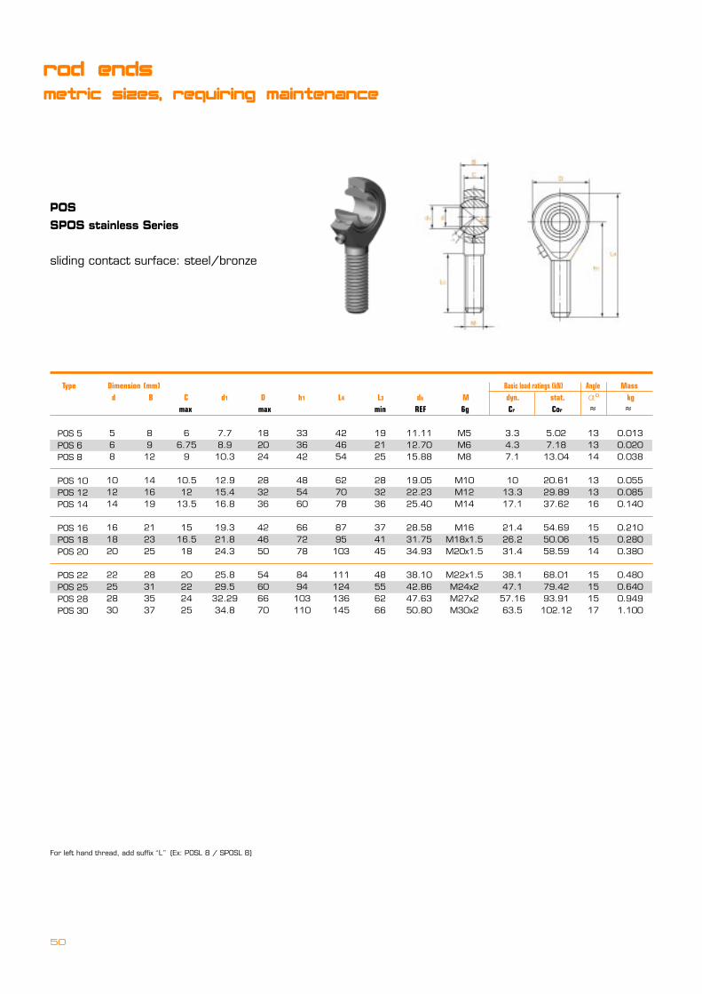
POSSPOS stainless Series
sliding contact surface: steel/bronze
POS 5POS 6POS 8
POS 10POS 12POS 14
POS 16POS 18POS 20
POS 22POS 25POS 28POS 30
Type Dimension (mm) Basic load ratings (kN) Angle Mass d B C d1 D h1 L4 L3 dk M dyn. stat. � kg max max min REF 6g Cr Cor � �
o
568
101214
161820
22252830
8912
141619
212325
28313537
66.75
9
10.512
13.5
1516.518
20222425
7.78.910.3
12.915.416.8
19.321.824.3
25.829.532.2934.8
182024
283236
424650
54606670
333642
485460
667278
8494103110
424654
627078
8795103
111124136145
192125
283236
374145
48556266
11.1112.7015.88
19.0522.2325.40
28.5831.7534.93
38.1042.8647.6350.80
M5M6M8
M10M12M14
M16M18x1.5M20x1.5
M22x1.5M24x2M27x2M30x2
3.34.37.1
1013.317.1
21.426.231.4
38.147.157.1663.5
5.027.1813.04
20.6129.8937.62
54.6950.0658.59
68.0179.4293.91102.12
131314
131316
151514
15151517
0.0130.0200.038
0.0550.0850.140
0.2100.2800.380
0.4800.6400.9491.100
For left hand thread, add suffix�L� (Ex: POSL 8 / SPOSL 8)
51
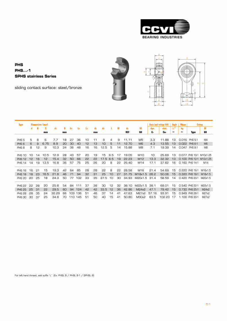
PHSPHS...-1SPHS stainless Series
sliding contact surface: steel/bronze
For left hand thread, add suffix�L� (Ex: PHSL 8 / PHSL 8-1 / SPHSL 8)
PHS 5PHS 6PHS 8
PHS 10PHS 12PHS 14
PHS 16PHS 18PHS 20
PHS 22PHS 25PHS 28PHS 30
568
101214
161820
22252830
8912
141619
212325
28313537
66.75
9
10.512
13.5
1516.518
20222425
7.78.910.3
12.915.416.8
19.321.824.3
25.829.532.2934.8
182024
283236
424650
54606670
273036
435057
647177
8494103110
364048
576675
8594102
111124136145
101216
202225
283233
37425151
111316
192226
283135
38424650
910
12.5
1517.520
2225
27.5
3033.53740
455
6.56.58
81010
12121415
91114
171922
222730
32364141
11.1112.7015.88
19.0522.2325.40
28.5831.7534.93
38.1042.8647.6350.80
M5M6M8
M10M12M14
M16M18x1.5M20x1.5
M22x1.5M24x2M27x2M30x2
3.34.37.1
1013.317.1
21.426.231.4
38.147.157.1663.5
11.8813.5519.39
25.6932.3237.62
54.6950.0658.59
68.0179.4293.91102.23
0.0160.0220.047
0.0770.1000.160
0.2200.3200.420
0.5400.7300.9491.100
PHS 5-1PHS 6-1PHS 8-1
PHS 10-1PHS 12-1PHS 14-1
PHS 16-1PHS 18-1PHS 20-1
PHS 22-1PHS 25-1PHS 28-1PHS 30-1
M4M6M8
M10x1.25M12x1.25
M14
M16x1.5M18x1.5M20x1.5
M22x1.5M24x2M27x2M27x2
131314
131316
151514
15151517
Type === Dimension (mm) Basic load ratings (kN) Angle Mass Cetop d B C d1 D h1 L4 L3 d5 d4 L W dk M dyn. stat. � kg M max max max REF 6H Cr Cor � � Type 6H
o
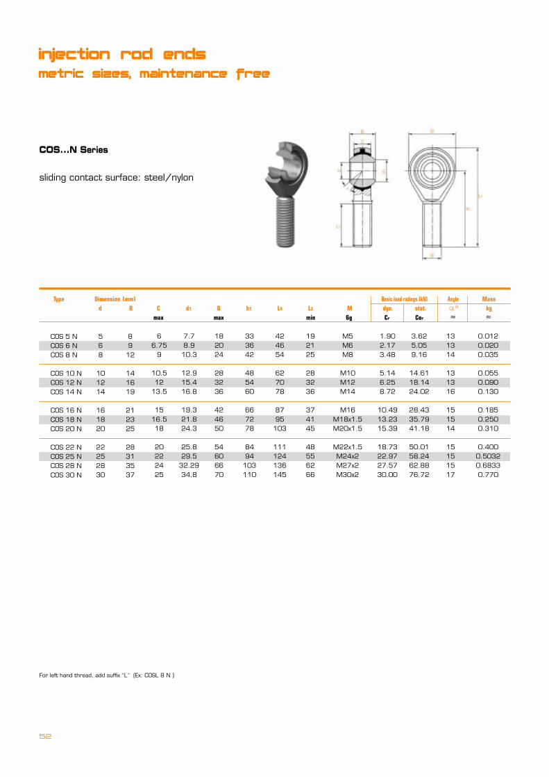
52
injection rod ends
metric sizes, maintenance free
COS...N Series
sliding contact surface: steel/nylon
For left hand thread, add suffix�L� (Ex: COSL 8 N )
COS 5 NCOS 6 NCOS 8 N
COS 10 NCOS 12 NCOS 14 N
COS 16 NCOS 18 NCOS 20 N
COS 22 NCOS 25 NCOS 28 NCOS 30 N
Type === Dimension (mm) Basic load ratings (kN) Angle Mass d B C d1 D h1 L4 L3 M dyn. stat. � kg max max min 6g Cr Cor � �
o
568
101214
161820
22252830
8912
141619
212325
28313537
66.75
9
10.512
13.5
1516.518
20222425
7.78.910.3
12.915.416.8
19.321.824.3
25.829.5
32.2934.8
182024
283236
424650
54606670
333642
485460
667278
8494
103110
424654
627078
8795
103
111124136145
192125
283236
374145
48556266
M5M6M8
M10M12M14
M16M18x1.5M20x1.5
M22x1.5M24x2M27x2M30x2
1.902.173.48
5.146.258.72
10.4913.2315.39
18.7322.9727.5730.00
3.625.059.16
14.6118.1424.02
28.4335.7941.18
50.0158.2462.8876.72
131314
131316
151514
15151517
0.0120.0200.035
0.0550.0900.130
0.1850.2500.310
0.4000.50320.68330.770

53
CHS...N Series
sliding contact surface: steel/nylon
For left hand thread, add suffix�L� (Ex: CHSL 8 N)
CHS 5 NCHS 6 NCHS 8 N
CHS 10 NCHS 12 NCHS 14 N
CHS 16 NCHS 18 NCHS 20 N
CHS 22 NCHS 25 NCHS 28 NCHS 30 N
Type === Dimension (mm) Basic load ratings (kN) Angle Mass d B C d1 D h1 L4 L3 d5 d4 L W M dyn. stat. � kg max max min max max max 6H Cr Cor � �
568
101214
161820
22252830
8912
141619
212325
28313537
66.75
9
10.512
13.5
1516.518
20222425
7.78.910.3
12.915.416.8
19.321.824.3
25.829.5
32.2934.8
182024
283236
424650
54606670
273036
435057
647177
8494103110
364048
576675
8594102
111124136145
101216
202225
283233
37425151
111316
192226
283135
38424650
910
12.5
1517.520
2225
27.5
3033.53740
M5M6M8
M10M12M14
M16M18x1.5M20x1.5
M22x1.5M24x2M27x2M30x2
91114
171922
222730
32364141
1.902.173.48
5.146.258.72
10.4913.2315.39
18.7322.9727.5730.00
5.987.5510.29
14.6118.1424.02
28.4335.7941.18
50.0158.2462.8876.72
0.0150.0200.045
0.0700.0900.150
0.2000.2900.380
0.4800.5700.7120.825
o
455
6.56.58
81010
12121415
131314
131316
151514
15151517

54
EM Series
sliding contact surface: steel/steel
.1900
.2500
.2500
.3125
.3125
.3750
.4375
.5000
.6250
.6250
.7500
.7570
EM 3*EM 4*EM 4-5*
EM 5*EM 5-6EM 6
EM 7EM 8EM 10
EM 10-12EM 12EM 12-757
.312
.375
.375
.437
.437
.500
.562
.625
.750
.750
.875
.875
1.2501.5621.875
1.8751.9381.938
2.1252.4382.625
2.8752.8752.875
.625
.750
.875
.8751.0001.000
1.1251.3121.500
1.7501.7501.750
.437
.500
.500
.625
.625
.719
.812
.9371.125
1.1251.3121.312
.7501.0001.250
1.2501.2501.250
1.3751.5001.625
1.7501.7501.750
10-321/4-285/16-24
5/16-243/8-243/8-24
7/16-201/2-205/8-18
3/4-163/4-163/4-16
202727
222222
212026
262424
1,3842,5434,574
4,1135,5445,828
7,2969,58811,169
16,80716,33816,338
.03
.04
.07
.07
.11
.11
.15
.24
.36
.57
.57
.57
.234
.250
.250
.312
.312
.359
.406
.453
.484
.484
.593
.593
commercial rod ends
inch sizes
Type Dimension (inch) thread Angle Mass d D B C dk Ball Dia. L3 � UNF 3A LBS � LBS
o
+.062-.031
Ultimate Rodial Static
Load Capacity
For grease fitting, add�Z�to part number. Ex: EM 8 Z (See zerk option on page 39 )For left hand thread, add�L�to part number. Ex: EML 8For stud, add�S�to part number. Ex: EM 8 S (See stud dimensions on page 39 )For PTFE liner, add�T�to part number. Ex: EM 8 T
Note: * Grease fitting not available on these sizes. Units are supplied without grease fittings.

55
EF Series
sliding contact surface: steel/steel
.1900
.2500
.2500
.3125
.3125
.3750
.3125
.4375
.5000
.6250
.6250
.7500
EF 3*EF 4*EF 4-5*
EF 5*EF 5-6EF 6
EF 6XEF 7EF 8
EF 10EF 10-12EF 12
.312
.375
.375
.437
.437
.500
.512
.562
.625
.750
.750
.875
1.0621.3121.375
1.3751.6251.625
1.6251.8122.125
2.5002.8752.875
.625
.750
.875
.8751.0001.000
1.0001.1251.312
1.5001.7501.750
.437
.500
.500
.625
.625
.719
.719
.8120973
1.1251.1251.312
.500
.687
.687
.687
.812
.812
.781
.9371.062
1.3750.5621.562
10-321/4-285/16-24
5/16-243/8-243/8-24
3/8-247/16-201/2-20
5/8-163/4-163/4-16
202727
222222
222120
262624
1,3843,4684,574
4,3975,5445,087
5,0877,34210,460
16,80716,33816,338
0.040.050.08
0.080.130.13
0.130.180.29
0.430.650.65
.234
.250
.250
.312
.312
.359
.331
.406
.453
.484
.484
.593
.406
.469
.500
.500
.687
.687
.687
.750
.875
1.0001.1251.125
.312
.375
.437
.437
.562
.562
.562
.625
.750
.8751.0001.000
Type Dimension (inch) thread Angle Mass d D B C dk S d4 Ball Dia. L3 � UNF 2B LBS � LBS
o+.062-.031
Ultimate Rodial Static
Load Capacity
For grease fitting, add�Z�to part number. Ex: EF 8 Z (See zerk option on page 39 )For left hand thread, add�L�to part number. Ex: EFL 8For stud, add�S�to part number. Ex: EF 8 S (See stud dimensions on page 39 )For PTFE liner, add�T�to part number. Ex: EF 8 T
Note: * Grease fitting not available on these sizes. Units are supplied without grease fittings.
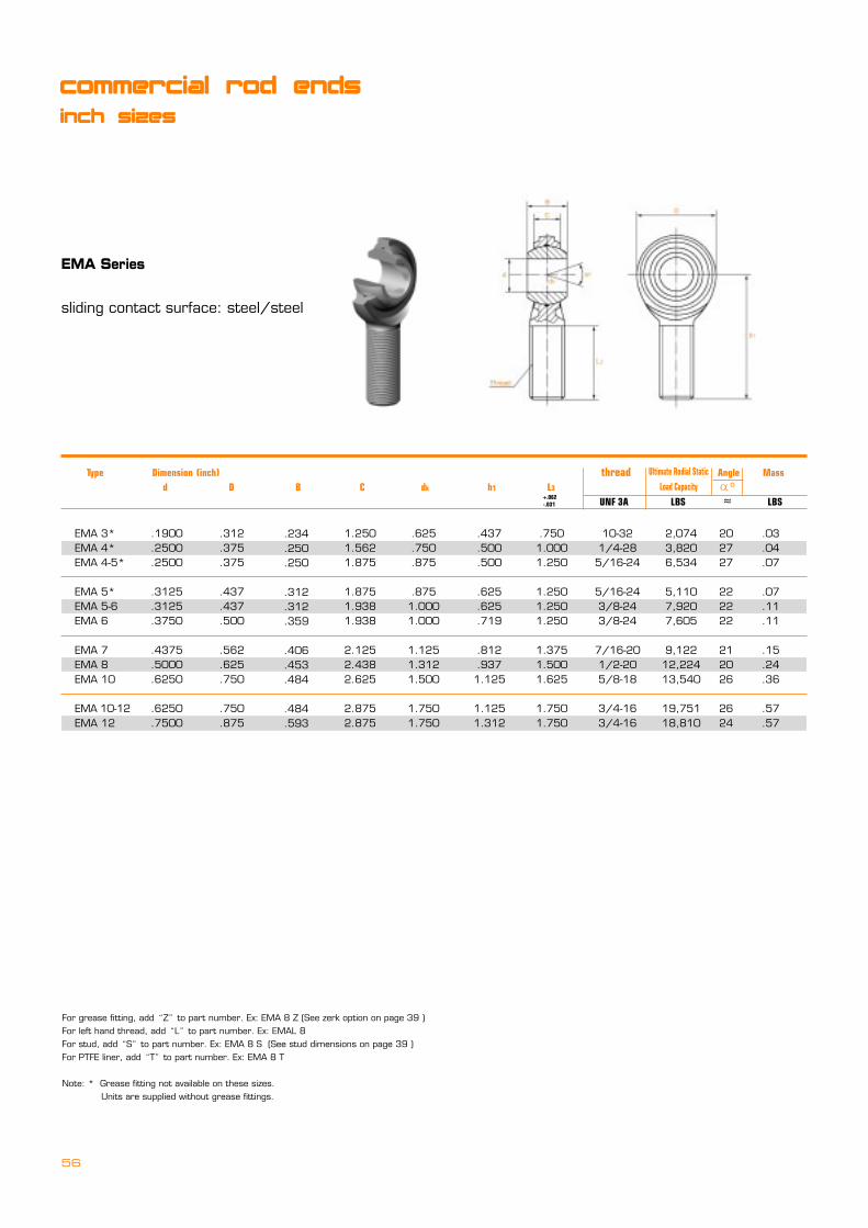
56
EMA Series
sliding contact surface: steel/steel
.1900
.2500
.2500
.3125
.3125
.3750
.4375
.5000
.6250
.6250
.7500
EMA 3*EMA 4*EMA 4-5*
EMA 5*EMA 5-6EMA 6
EMA 7EMA 8EMA 10
EMA 10-12EMA 12
.312
.375
.375
.437
.437
.500
.562
.625
.750
.750
.875
1.2501.5621.875
1.8751.9381.938
2.1252.4382.625
2.8752.875
.625
.750
.875
.8751.0001.000
1.1251.3121.500
1.7501.750
.437
.500
.500
.625
.625
.719
.812
.9371.125
1.1251.312
.7501.0001.250
1.2501.2501.250
1.3751.5001.625
1.7501.750
10-321/4-285/16-24
5/16-243/8-243/8-24
7/16-201/2-205/8-18
3/4-163/4-16
202727
222222
212026
2624
2,0743,8206,534
5,1107,9207,605
9,12212,22413,540
19,75118,810
.03
.04
.07
.07
.11
.11
.15
.24
.36
.57
.57
.234
.250
.250
.312
.312
.359
.406
.453
.484
.484
.593
Type Dimension (inch) thread Angle Mass d D B C dk h1 L3 � UNF 3A LBS � LBS
o
+.062-.031
Ultimate Rodial Static
Load Capacity
commercial rod ends
inch sizes
For grease fitting, add�Z�to part number. Ex: EMA 8 Z (See zerk option on page 39 )For left hand thread, add�L�to part number. Ex: EMAL 8For stud, add�S�to part number. Ex: EMA 8 S (See stud dimensions on page 39 )For PTFE liner, add�T�to part number. Ex: EMA 8 T
Note: * Grease fitting not available on these sizes. Units are supplied without grease fittings.
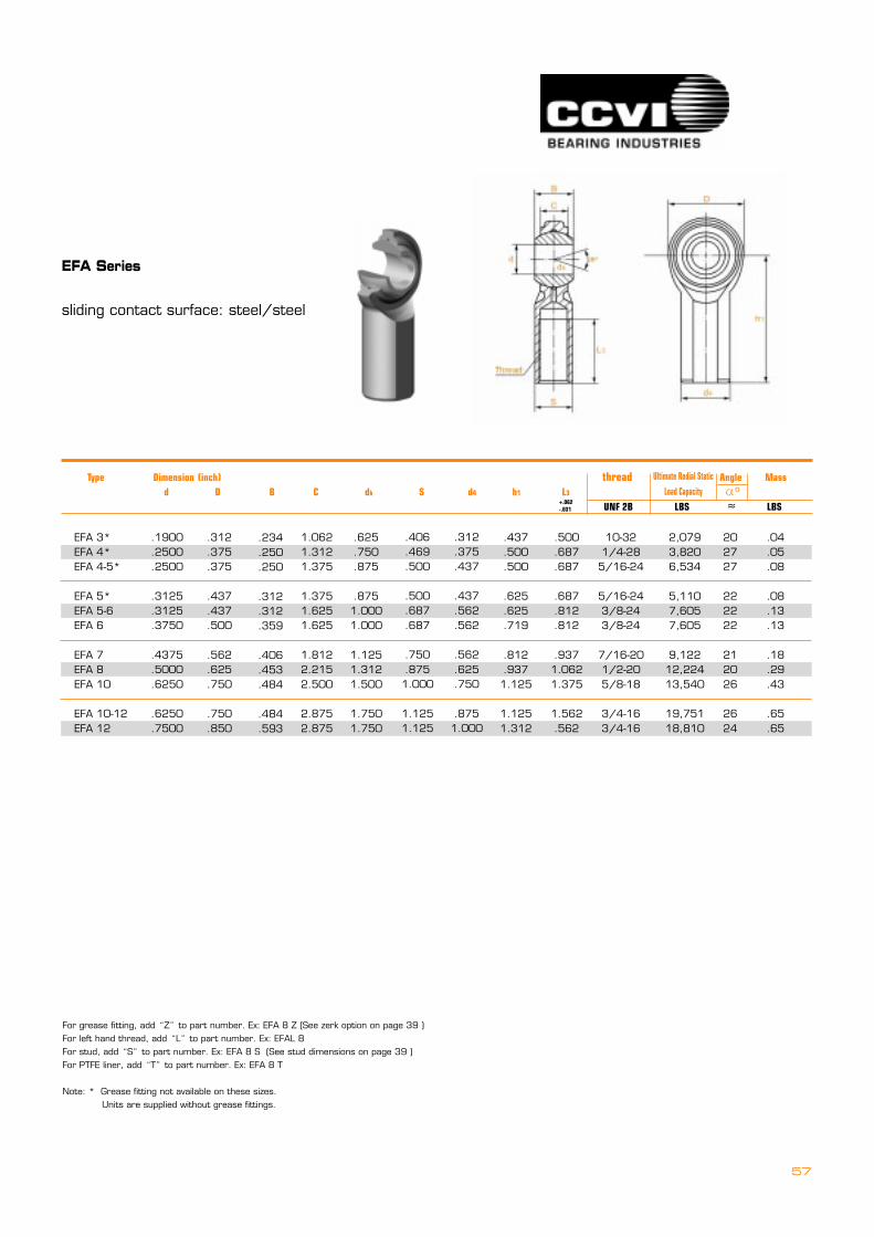
57
EFA Series
sliding contact surface: steel/steel
.1900
.2500
.2500
.3125
.3125
.3750
.4375
.5000
.6250
.6250
.7500
EFA 3*EFA 4*EFA 4-5*
EFA 5*EFA 5-6EFA 6
EFA 7EFA 8EFA 10
EFA 10-12EFA 12
.312
.375
.375
.437
.437
.500
.562
.625
.750
.750
.850
1.0621.3121.375
1.3751.6251.625
1.8122.2152.500
2.8752.875
.625
.750
.875
.8751.0001.000
1.1251.3121.500
1.7501.750
.437
.500
.500
.625
.625
.719
.812
.9371.125
1.1251.312
.500
.687
.687
.687
.812
.812
.9371.0621.375
1.562.562
10-321/4-285/16-24
5/16-243/8-243/8-24
7/16-201/2-205/8-18
3/4-163/4-16
202727
222222
212026
2624
2,0793,8206,534
5,1107,6057,605
9,12212,22413,540
19,75118,810
.04
.05
.08
.08
.13
.13
.18
.29
.43
.65
.65
.234
.250
.250
.312
.312
.359
.406
.453
.484
.484
.593
.406
.469
.500
.500
.687
.687
.750
.8751.000
1.1251.125
.312
.375
.437
.437
.562
.562
.562
.625
.750
.8751.000
Type Dimension (inch) thread Angle Mass d D B C dk S d4 h1 L3 � UNF 2B LBS � LBS
o
+.062-.031
Ultimate Rodial Static
Load Capacity
For grease fitting, add�Z�to part number. Ex: EFA 8 Z (See zerk option on page 39 )For left hand thread, add�L�to part number. Ex: EFAL 8For stud, add�S�to part number. Ex: EFA 8 S (See stud dimensions on page 39 )For PTFE liner, add�T�to part number. Ex: EFA 8 T
Note: * Grease fitting not available on these sizes. Units are supplied without grease fittings.

58
MA Series
sliding contact surface: steel/steel
.1900
.2500
.3125
.3750
.4375
.5000
.6250
.7500
.7500
.8750
.8750
1.00001.00001.0000
MA 3MA 4MA 5
MA 6MA 7MA 8
MA 10MA 12MA 12-20
MA 14MA 14-1
MA 16MA 16-1MA 16-2
.312
.375
.437
.500
.562
.625
.750
.875
.875
.875
.875
1.3751.3751.375
1.2501.5621.875
1.9382.2152.438
2.6252.8752.875
3.3753.375
4.1254.1254.125
.625
.750
.875
1.0001.1251.312
1.5001.7501.750
2.0002.000
2.7502.7502.750
.437
.500
.625
.719
.812
.937
1.1251.3121.312
1.3751.312
1.8751.8751.875
.7501.0001.250
1.2501.3751.500
1.6251.7501.750
2.0001.875
2.1252.1252.125
10-321/4-285/16-24
3/8-247/16-241/2-20
5/8-183/4-167/8-14
7/8-147/8-14
1 1/4-121-14*1-12
131614
121412
161414
712
171717
2,8515,2607,639
9,54410,28516,238
17,95528,08128,081
45,05155,692
76,20076,20076,200
.028
.043
.072
.112
.160
.249
.382
.602
.720
.906
.906
2.4062.1272.127
.250
.281
.344
.406
.437
.500
.562
.687
.687
.765
.687
1.0001.0001.000
W
B
H
Thread
ao
C
D
A
precision rod ends
inch sizes
Type Dimension (inch) thread Angle Mass d D B C dk h1 L3 � UNF 3A LBS � LBS
o
Ultimate Rodial Static
Load Capacity
Units are supplied without grease fittings.For grease fitting, add�Z�to part number. Ex: MA 8 Z (See zerk option on page 39 )For left hand thread, add�L�to part number. Ex: MAL 8For stud, add�S�to part number. Ex: MA 8 S (See stud dimensions on page 39 )For PTFE liner, add�T�to part number. Ex: MA 8 T
Note: * Thread 1-14 UNS

59
FA Series
sliding contact surface: steel/steel
.1900
.2500
.3125
.3750
.4375
.5000
.6250
.7500
.8750
1.00001.00001.0000
FA 3FA 4FA 5
FA 6FA 7FA 8
FA 10FA 12FA 14
FA 16FA 16-1FA 16-2
.312
.375
.437
.500
.562
.625
.750
.875
.875
1.3751.3751.375
1.0621.3121.375
1.6251.8122.125
2.5002.8753.375
4.1254.1254.125
.625
.750
.875
1.0001.1251.312
1.5001.7501.750
2.7502.7502.750
.437
.500
.625
.719
.812
.937
1.1251.3121.312
1.8751.8751.875
.562
.750
.750
.9371.0621.187
1.5001.7501.875
2.1252.1252.125
10-321/4-285/16-24
3/8-247/16-241/2-20
5/8-183/4-167/8-14
1 1/4-121-14*1-12
202727
222222
212026
2624
2,0793,8206,534
5,1107,6057,605
9,12212,22413,540
19,75118,810
.04
.05
.08
.08
.13
.13
.18
.29
.43
.65
.65
.250
.281
.344
.406
.437
.500
.562
.687
.687
1.0001.0001.000
.406
.469
.500
.687
.750
.875
1.0001.1251.300
1.6251.6251.625
.312
.375
.437
.562
.625
.750
.8751.0001.125
1.5001.5001.500
W
B
H
Thread
ao
C
D
A
K
Type Dimension (inch) thread Angle Mass d D B C dk S d4 h1 L3 � UNF 2B LBS � LBS
o
Ultimate Rodial Static
Load Capacity
Units are supplied without grease fittings.For grease fitting, add�Z�to part number. Ex: FA 8 Z (See zerk option on page 39 )For left hand thread, add�L�to part number. Ex: FAL 8For stud, add�S�to part number. Ex: FA 8 S (See stud dimensions on page 39 )For PTFE liner, add�T�to part number. Ex: FA 8 T
Note: * Thread 1-14 UNS

60
MC Series
sliding contact surface: steel/steel
.1900
.2500
.3125
.3750
.4375
.5000
.6250
.7500
.8750
.87501.00001.00001.0000
MC 3MC 4MC 5
MC 6MC 7MC 8
MC 10MC 12MC 14
MC 14-1MC 16MC 16-1MC 16-2
.312
.375
.437
.500
.562
.625
.750
.875
.875
.8751.3751.3751.375
.250
.281
.344
.406
.437
.500
.562
.687
.765
.6871.0001.0001.000
1.2501.5621.875
1.9382.1252.438
2.6252.8753.375
3.3754.1254.1254.125
.625
.750
.875
1.0001.1251.312
1.5001.7502.000
2.0002.7502.7502.750
.437
.500
.625
.719
.812
.937
1.1251.3121.375
1.3121.8751.8751.875
.7501.0001.250
1.2501.3751.500
1.6251.7502.000
1.8752.1252.1252.125
10-321/4-285/16-24
3/8-247/16-201/2-20
5/8-183/4-167/8-14
7/8-1411/4-121-14�
1-12
131614
121412
16147
12171717
1,1692,1582,784
3,9154,2186,660
7,36411,51818,476
22,84343,54143,54143,541
.028
.043
.072
.112
.160
.249
.382
.602
.906
.9062.4062.1272.127
precision rod ends
inch sizes
Type Dimension (inch) B W H A D Ball Dia. C �o
UNF 3A � LBS LBSREF +.062-.031
Ultimate Rodial Static
Load Capacity
Units are supplied without grease fittings.For grease fitting, add�Z�to part number. Ex: MC 8 Z (See zerk option on page 39 )For left hand thread, add�L�to part number. Ex: MCL 8For stud, add�S�to part number. Ex: MC 8 S (See stud dimensions on page 39 )For PTFE liner, add�T�to part number. Ex: MC 8 T
Note: * Thread 1-14 UNS
Thread Angle Mass
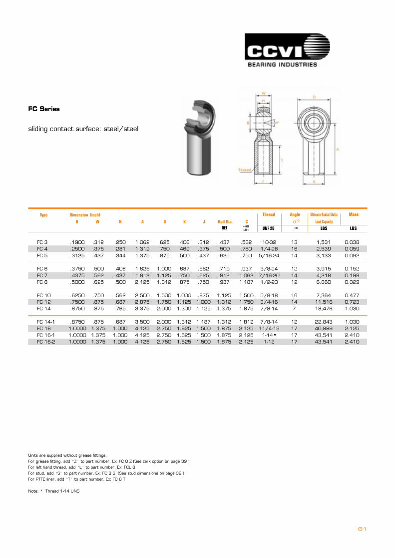
61
FC Series
sliding contact surface: steel/steel
.1900
.2500
.3125
.3750
.4375
.5000
.6250
.7500
.8750
.87501.00001.00001.0000
FC 3FC 4FC 5
FC 6FC 7FC 8
FC 10FC 12FC 14
FC 14-1FC 16FC 16-1FC 16-2
.312
.375
.437
.500
.562
.625
.750
.875
.875
.8751.3751.3751.375
.250
.281
.344
.406
.437
.500
.562
.687
.765
.6871.0001.0001.000
1.0621.3121.375
1.6251.8122.125
2.5002.8753.375
3.5004.1254.1254.125
.625
.750
.875
1.0001.1251.312
1.5001.7502.000
2.0002.7502.7502.750
.406
.469
.500
.687
.750
.875
1.0001.1251.300
1.3121.6251.6251.625
.312
.375
.437
.562
.625
.750
.8751.0001.125
1.1871.5001.5001.500
.437
.500
.625
.719
.812
.937
1.1251.3121.375
1.3121.8751.8751.875
.562
.750
.750
.9371.0621.187
1.5001.7501.875
1.8122.1252.1252.125
10-321/4-285/16-24
3/8-247/16-201/2-20
5/8-183/4-167/8-14
7/8-1411/4-121-14�
1-12
131614
121412
16147
12171717
1,5312,5393,133
3,9154,2186,660
7,36411,51818,476
22,84340,88943,54143,541
0.0380.0590.092
0.1520.1980.329
0.4770.7231.030
1.0302.1252.4102.410
Type Dimension (inch) B W H A D K J Ball Dia. C ====�o
UNF 2B � LBS LBSREF +.062-.031
Ultimate Rodial Static
Load Capacity
Units are supplied without grease fittings.For grease fitting, add�Z�to part number. Ex: FC 8 Z (See zerk option on page 39 )For left hand thread, add�L�to part number. Ex: FCL 8For stud, add�S�to part number. Ex: FC 8 S (See stud dimensions on page 39 )For PTFE liner, add�T�to part number. Ex: FC 8 T
Note: * Thread 1-14 UNS
Thread Angle Mass
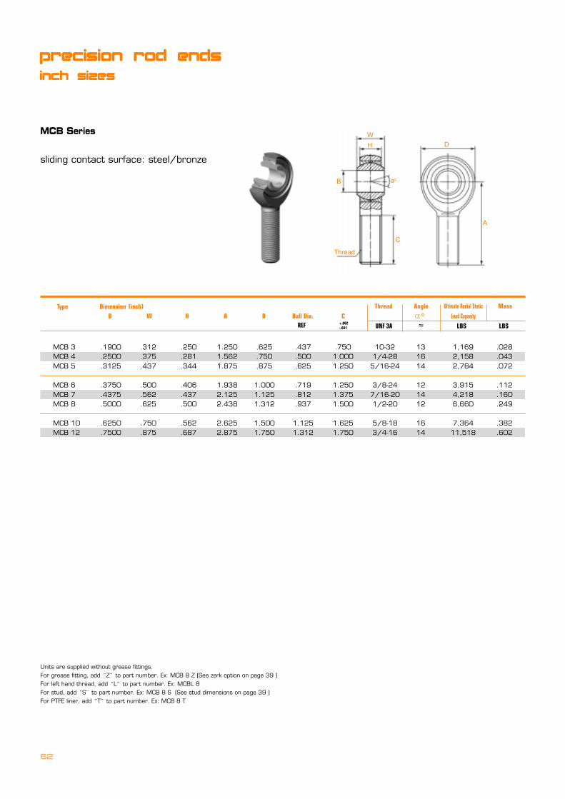
62
MCB Series
sliding contact surface: steel/bronze
W
B
H
Thread
ao
C
D
A
.1900
.2500
.3125
.3750
.4375
.5000
.6250
.7500
MCB 3MCB 4MCB 5
MCB 6MCB 7MCB 8
MCB 10MCB 12
.312
.375
.437
.500
.562
.625
.750
.875
.250
.281
.344
.406
.437
.500
.562
.687
1.2501.5621.875
1.9382.1252.438
2.6252.875
.625
.750
.875
1.0001.1251.312
1.5001.750
.437
.500
.625
.719
.812
.937
1.1251.312
.7501.0001.250
1.2501.3751.500
1.6251.750
10-321/4-285/16-24
3/8-247/16-201/2-20
5/8-183/4-16
131614
121412
1614
1,1692,1582,784
3,9154,2186,660
7,36411,518
.028
.043
.072
.112
.160
.249
.382
.602
Type Dimension (inch) B W H A D Ball Dia. C ========�o
UNF 3A � LBS LBSREF +.062-.031
Ultimate Rodial Static
Load Capacity
precision rod ends
inch sizes
Units are supplied without grease fittings.For grease fitting, add�Z�to part number. Ex: MCB 8 Z (See zerk option on page 39 )For left hand thread, add�L�to part number. Ex: MCBL 8For stud, add�S�to part number. Ex: MCB 8 S (See stud dimensions on page 39 )For PTFE liner, add�T�to part number. Ex: MCB 8 T
Thread Angle Mass
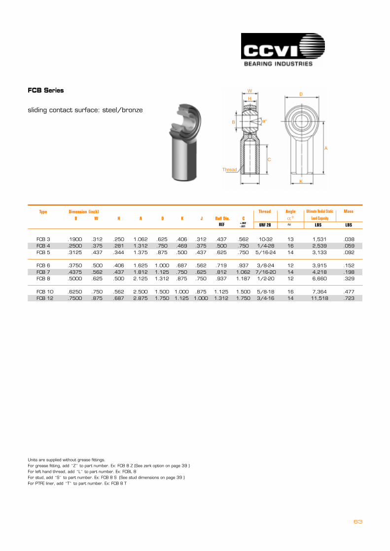
63
FCB Series
sliding contact surface: steel/bronze
W
B
H
Thread
ao
C
D
A
K
.1900
.2500
.3125
.3750
.4375
.5000
.6250
.7500
FCB 3FCB 4FCB 5
FCB 6FCB 7FCB 8
FCB 10FCB 12
.312
.375
.437
.500
.562
.625
.750
.875
.250
.281
.344
.406
.437
.500
.562
.687
1.0621.3121.375
1.6251.8122.125
2.5002.875
.625
.750
.875
1.0001.1251.312
1.5001.750
.406
.469
.500
.687
.750
.875
1.0001.125
.312
.375
.437
.562
.625
.750
.8751.000
.437
.500
.625
.719
.812
.937
1.1251.312
.562
.750
.750
.9371.0621.187
1.5001.750
10-321/4-285/16-24
3/8-247/16-201/2-20
5/8-183/4-16
131614
121412
1614
1,5312,5393,133
3,9154,2186,660
7,36411,518
.038
.059
.092
.152
.198
.329
.477
.723
Type Dimension (inch) B W H A D K J Ball Dia. C ========�o
UNF 2B � LBS LBSREF +.062-.031
Ultimate Rodial Static
Load Capacity
Units are supplied without grease fittings.For grease fitting, add�Z�to part number. Ex: FCB 8 Z (See zerk option on page 39 )For left hand thread, add�L�to part number. Ex: FCBL 8For stud, add�S�to part number. Ex: FCB 8 S (See stud dimensions on page 39 )For PTFE liner, add�T�to part number. Ex: FCB 8 T
Thread Angle Mass

64
MCN Series
sliding contact surface: steel/nylon
.1900
.2500
.3125
.3750
.4375
.5000
.6250
.7500
MCN 3 YMCN 4 YMCN 5 Y
MCN 6 YMCN 7 YMCN 8 Y
MCN 10 YMCN 12 Y
.312
.375
.437
.500
.562
.625
.750
.875
.250
.281
.344
.406
.437
.500
.562
.687
1.2501.5621.875
1.9372.1252.437
2.6252.875
.625
.750
.875
1.0001.1251.312
1.5001.750
.438
.516
.625
.719
.812
.938
1.1251.312
.7501.0001.250
1.2501.3721.500
1.6251.750
10-321/4-285/16-24
3/8-247/16-201/2-20
5/8-183/4-16
131614
121412
1614
1,2102,4702,740
4,2105,3506,430
8,30010,900
.023
.040
.071
.107
.148
.232
.364
.568
injection rod ends
inch sizes
�.06
Type Dimension (inch) B W H A D Ball Dia. C =========�o
UNF 2A � LBS LBSREF
Ultimate Rodial Static
Load Capacity
Units are supplied without grease fittings.For left hand thread, add�L�to part number. Ex: MCNL 8 YFor stud, add�S�to part number. Ex: MCN 8 Y S (See stud dimensions on page 39 )
Thread Angle Mass
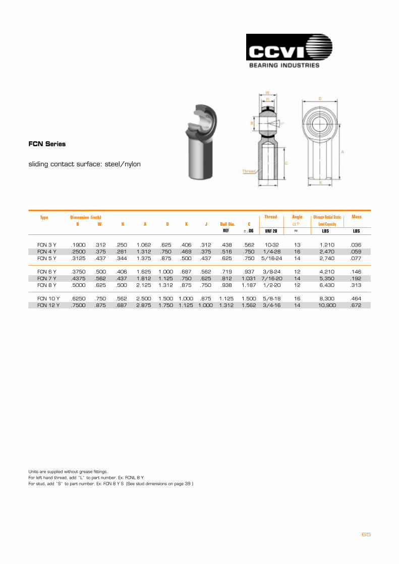
65
FCN Series
sliding contact surface: steel/nylon
.1900
.2500
.3125
.3750
.4375
.5000
.6250
.7500
FCN 3 YFCN 4 YFCN 5 Y
FCN 6 YFCN 7 YFCN 8 Y
FCN 10 YFCN 12 Y
.312
.375
.437
.500
.562
.625
.750
.875
.250
.281
.344
.406
.437
.500
.562
.687
1.0621.3121.375
1.6251.8122.125
2.5002.875
.625
.750
.875
1.0001.1251.312
1.5001.750
.406
.469
.500
.687
.750
.875
1.0001.125
.312
.375
.437
.562
.625
.750
.8751.000
.438
.516
.625
.719
.812
.938
1.1251.312
.562
.750
.750
.9371.0311.187
1.5001.562
10-321/4-285/16-24
3/8-247/16-201/2-20
5/8-183/4-16
131614
121412
1614
1,2102,4702,740
4,2105,3506,430
8,30010,900
.036
.059
.077
.146
.192
.313
.464
.672
�.06
Type Dimension (inch) B W H A D K J Ball Dia. C ========�o
UNF 2B � LBS LBSREF
Ultimate Rodial Static
Load Capacity
Units are supplied without grease fittings.For left hand thread, add�L�to part number. Ex: FCNL 8 YFor stud, add�S�to part number. Ex: FCN 8 Y S (See stud dimensions on page 39 )
Thread Angle Mass
66
NOTE