MECA0494 : Driveline systems€¦ · integrated into the same unit ... automatic unlock ... The...
54
MECA0494 : Driveline systems Part 3: Differentials Pierre Duysinx Research Center in Sustainable Automotive Technologies of University of Liege Academic Year 2017-2018 1
Transcript of MECA0494 : Driveline systems€¦ · integrated into the same unit ... automatic unlock ... The...

MECA0494 : Driveline systemsPart 3: Differentials
Pierre DuysinxResearch Center in Sustainable Automotive
Technologies of University of Liege
Academic Year 2017-2018
1

Bibliography
T. Gillespie. « Fundamentals of vehicle Dynamics », 1992, Society of Automotive Engineers (SAE)
J. Happian-Smith ed. « An introduction to modern vehicle design ». Butterworth-Heinemann. (2002)
H. Heisler. « Vehicle and Engine Technology ». 2nd edition. (1999) Butterworth Heineman.
D. Crolla. Ed. “Automotive engineering – Powertrain, chassis system, and vehicle body”. Elsevier Butterworh Heinemann (2009)
H. Mèmeteau. “Technologie fonctionnelle de l’automobile. 2. Transmission, train roulant et équipement électrique.” 4ème édition. Dunod (2002).
R. Langoria. « Vehicle Power Transmission: Concepts, Components, and Modelling ». Lecture notes of Vehicle System Dynamics and Control, The University of Texas at Austin, 2004.
2
Bibliography
http://www.howstuffworks.com
http://www.carbibles.com/transmission_bible.html
3

DIFFERENTIAL
4

DIFFERENTIAL SYSTEM
The differential enables a different rotation speed at the two wheels of the axles as in turns!)
The differential allows to deliver torques at left and right wheels even if they have different rotation speeds.
The device enables to split the power and allocate it unevenly to the two wheels
5

The differential concept
In straight line, the annulus gives rise to a rotation of the casing solely
In turns, the spinning of the planetary gears allows a different rottaion speed of the suns
6

THE DIFFERENTIAL
For vehicles with multiple live axles, there is a differential systems to split the power and the torque between the different axles. The central differential is also often called transaxle.
7
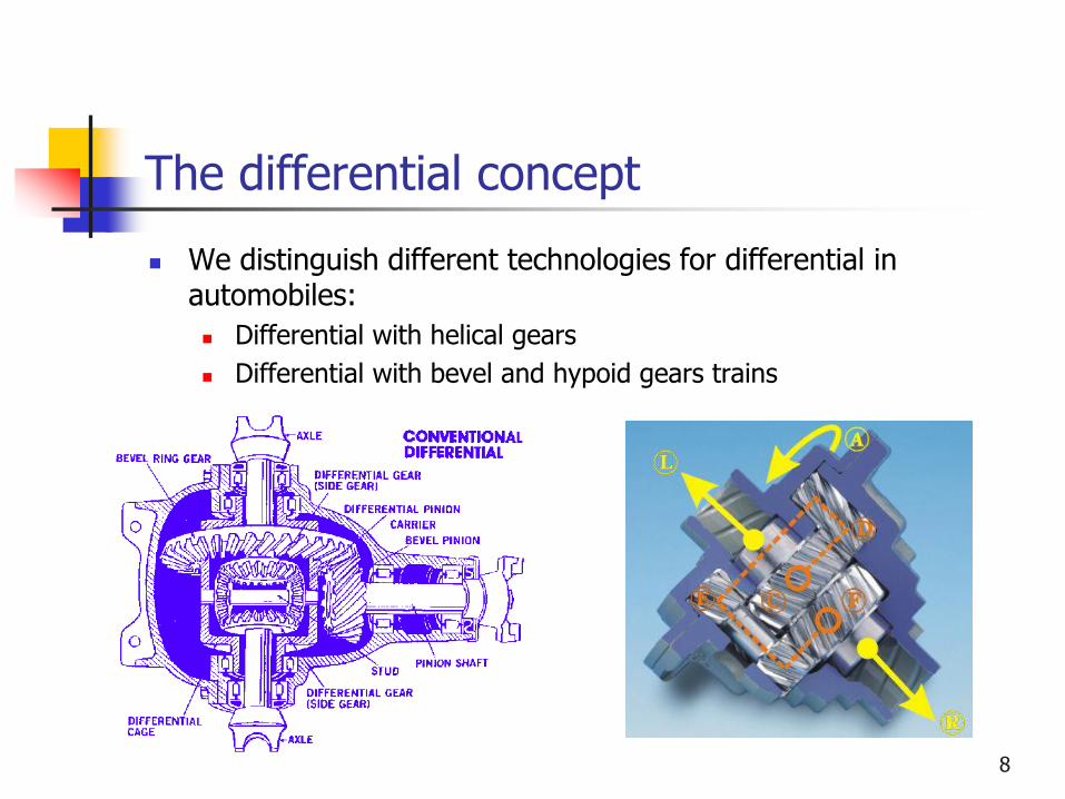
The differential concept
We distinguish different technologies for differential in automobiles:
Differential with helical gears
Differential with bevel and hypoid gears trains
8

Differential with bevel gears
Differentials with bevel gears can be regarded as planetary gear whose sun and annulus have the same diameters.
The only implementation possible is to have bevel gears between the sun and the planets and the planets and the annulus.
The planet carrier is the input of the differential system.
9

Differential with planetary gears
The planetary gears can be used as differential systems to produce unequal torque/speed distribution at the output shafts (and axles or wheels).
The input shaft is the planet carrier while the sun and the annulus are the output shafts.
The ratio between the two output torques is given by the ratio between the diameter of the sun and the annulus.
It is often the case for transfer boxes in all wheel drive vehicles.
10

Differential with planetary gears
Transfer box using a planetary gear
11

The differential concept
12

The differential concept
Velocities in points A and B
It comes if wg /= wd
A C planet pignon pignon g planet
B C planet pignon pignon d planet
v R R R
v R R R
w w w
w w w
2 0 ( )C planet g d planetR Rw w w
( )
2
g d
C
w ww
13

The differential concept
The equilibrium of torque gives:
g d CC C C
14

Operation of the differential
In straight line:
The resistance torques left / right are equal
There is no spinning of the (4) about their axis
Same rotation of output shafts (5) and (6)
In turn:
The rotation speeds of left and right axles are different
Satellites (4) have to spin about their axis.
Different rotation speed of the output axles left and right

Implementation of differential
16

Manual trans axels
For front wheel drive
vehicles, the gear box and
the differential are
integrated into the same unit
The sole difference is the
shape and the layout of the
components
Engine can be further
mounted longitudinally or
transversally
17

Slip control in differential
With an open differential, the engine torques are characterized by an equal distribution of the torque but an uneven distribution of the power between the wheels.
If a wheels is slipping (and spinning), the low mu slip wheel limits the torque available at the high mu slip wheel and one observes a transfer of the power to the fast spinning wheel.
The same problem happens one wheel lift off.
To circumvent the problem, it is necessary to block the differential i.e. to clamp one of the planet gears to the differential casing.
Devices to block differentials:
Self blocking differentials
Limited slip differential
Anti skid systems

Blocking the differential
The maximum torque that can be transferred to the wheels is governed by the wheel with the smallest friction torque that can transmitted between the two wheels or the two axles.
If the wheels were connected rigidly (at the price of a loss of a yaw torque) the maximum torque would be dictated by the maximum torque available at wheels.
To maintain a high transmissible torque, one resorts to blocking of the differential or better to a limited slip differential to maintain a better handling.
The locking is characterized by the ratio between the difference between the two torques and the input torque
max min
e
M MS
M
max mineM M M
19

Limited slip differentials
Limited slip differentials contains internal elements that can transfer the input torque to wheel shaft with the higher friction coefficient to the ground.
Usually this is made by friction elements which react to different rotation speed conditions. Some of the systems use gears, worm gears or hydraulic clutches.
Limited slip differential
20

Blocking the differential
One can distinguish three main categories of limited slip differential :
Differential with a manual engagement of the blocking mechanism
Differential with a limiting systems based on friction elements that are sensitive to differential rotation speed
Differential with friction regulated actively using electronic controller.
21

Blocking the differential
How to block the differential? A dog teeth system is linked to one of the
output wheel shaft and that can be translated freely on a splinned shaft
The dog teehth mounted on the differential
When the driver operate the stick, a fork moves the dog teeth that gear to the teeth made in the differential casing
The maneuver must be realized at standstill because if the wheel is slipping the high difference of speed between the casing and the wheel forbides to realize the maneuver.
Mémeteau Fig 7.1122

Blocking the differential
23

Blocking the differential
Such a blocking mechanism can be opertated manually whenever the speed is below 10 km/h
Above this critical speed, there is an automatic unlock automatically of the differential to avoid some bouncing behavior of the car while turning.
A gear pair of the planetary gear set is extended to allow for a synchronizing
A control fork to engage the clutch possibly using an actuator
Heisler (1999)24

Blocking the differential
The locking of the differential can be realized using friction elements that limit the difference in torques or in rotation speed between the two output shaft.
The most classical system is made of friction plates between the two output shafts
The torque difference between the two output shaft is fixed and the rate S is reduced with the ratio. The rate S is reduced with input torque.
25

Self locking differentials
The limited slip differential includes a locking system that becomes automatically active when the difference of rotation speeds between the two output shafts exceeds a threshold.
The working principle that is the most usual is based on the action of centrifugal loads that act onto brake pads of clutches to lock parts using friction.
The brake pads or clutch elements are linked to the wheel shafts while the brake drums are attached to the differential casing.
Another working principle is to take advantage of axial loads generated by helical gears. These forces leads to axial displacements and later to contact between friction elements.
26

Blocking the differential
The locking of the differential can be realized using a friction elements between the wheel shafts and the differential casing
Types of limited slip differential:
Using clutch plates (Sure-Grip, Positraction, Traction Lok)
Using conical clutches (ex. Borg-Warmer system)
The friction force is independent on the engine torque but it depends on the effort on the gear teeth pushing the gear wheels against the casing surfaces
27

Blocking the differential
28
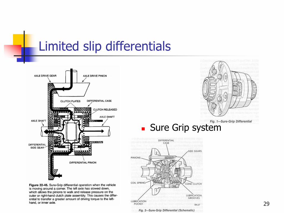
Limited slip differentials
Sure Grip system
29

Limited slip differentials
Types of limited slip differentials
Friction types: a small clutch disk is used (Sure-Grip, Positraction, Traction Lok) as well as conical gears.
Type of gears: Torsen et hypoid
Torsen differential 30

Differential locking
One of the most famous system is the TORSEN systems (for TORque SENsistive).
It is made of several gear pairs similar to worm gears and for which the helical angles has been optimized to have a self locking effect.
The helical angle is optimized to increase the friction in terms of different wheel torques.
31

Limited slip differential: TORSEN
TORSEN =TORqueSENsitive
32

Limited slip differential: TORSEN
33

Limited slip differential: TORSEN
A famous application: the Torsen differential in the Audi Quattro
34

Limited slip differential
Limited slip differential ZF
35

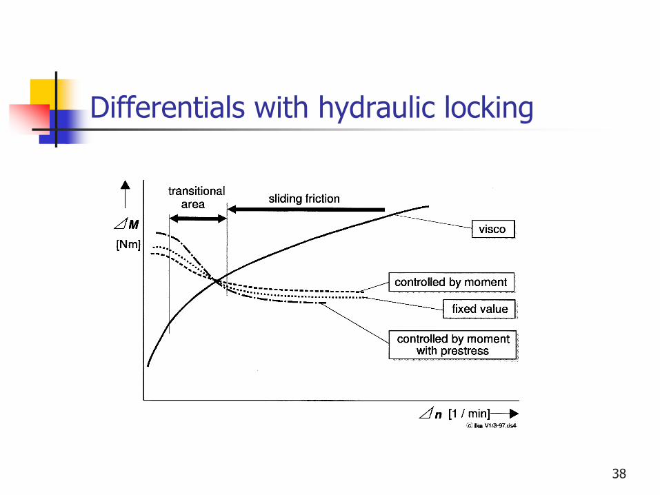
Differentials with hydraulic locking
The limited slip differential includes several locking elements based on the action of one or several clutch elements.
In a purely passive version, the visco-hydraulic coupling transfers the friction torque to the wall of the casing.
The friction torque depends on the shear velocity of the fluid and so on the relative velocity of the plates.
The set up of the systems depends on the experimental curves reporting the viscosity w.r.t. the temperature of the oil.
36

Differentials with hydraulic locking
37
Differentials with hydraulic locking
38
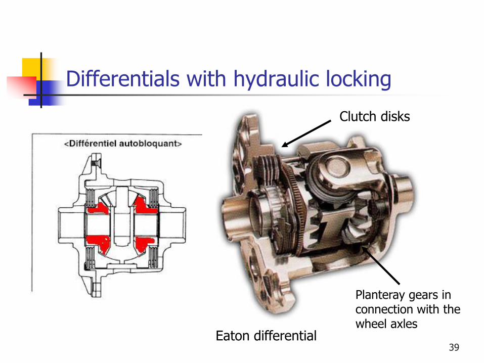
Differentials with hydraulic locking
Eaton differential
Clutch disks
Planteray gears in connection with the wheel axles
39

Differentials with hydraulic locking
The system can be further improved by including an active system able to modify the friction on demand.
The HALDEX systems uses the pressure oil
40

Differentials with hydraulic locking
Haldex System 41

TRANSMISSION SHAFTS
42

Arbres de transmission : propulsion
L’arbre de sortie de la boite est connecté au différentiel via un arbre de transmission
L’arbre de transmission est généralement creux et doit être flexible
Pour permettre le mouvement relatif, un joint de cardan est utilisé à chaque bout
Attention au montage homocinétique des joints de cardan pour éviter les fluctuations de vitesse)
Pour autoriser le débattement de suspension, on place un joint prismatique
43

Transmission shaft for rear live axles
44

Universal (Hooke) joints
Différentes réalisations des joints de Cardan ou universel
45

Transmission shaft for rear live axles
Parfois, la longueur de l’arbreabaisse trop fortement la fréquence naturelle de l’arbre
On peut alors placer un supportintermédiaire pour remonter lesfréquences
46

Transmission shaft for rear live axles
L’arbre de transmission fait tourner le différentiel, les essieux, les roues
La force propulsive développée entre le sol et le pneu passe à travers le support de l’essieu et va vers le châssis à travers les ressorts à lame, puis les attaches au châssis et à travers les barres de guidage
Dans ce cas, on ne doit donc pas tenir compte des forces propulsives dans la transmission
47

Transmission shaft for front live axles
48
Transmission shaft for front live axles
49
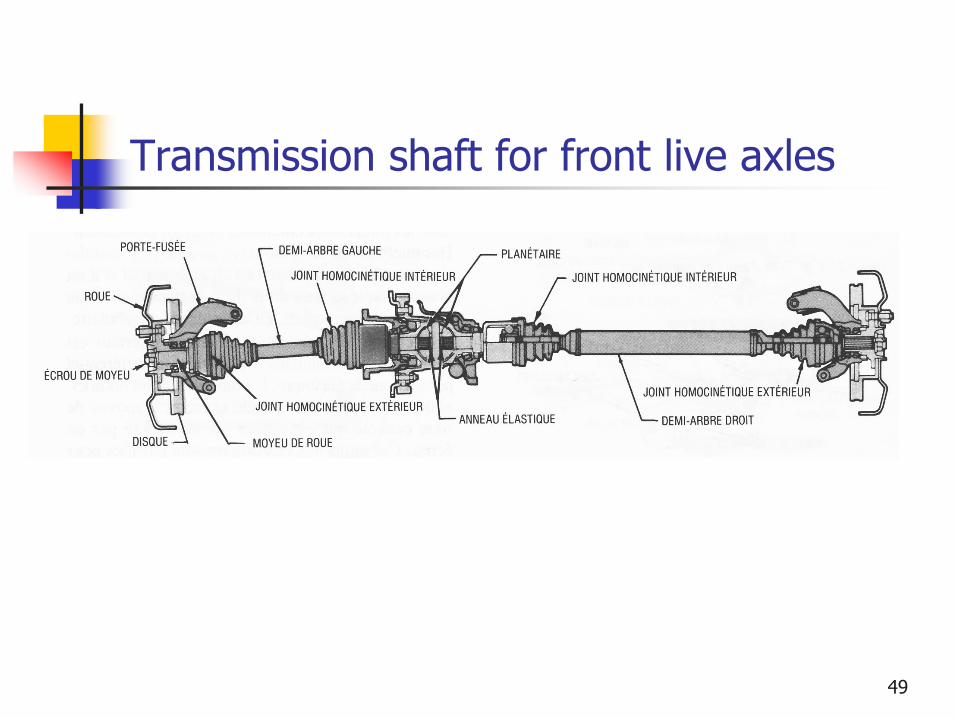
Transmission shaft for front live axles
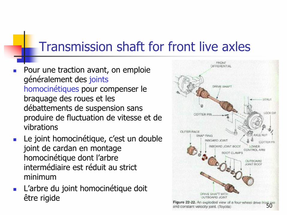
Pour une traction avant, on emploie généralement des joints homocinétiques pour compenser le braquage des roues et les débattements de suspension sans produire de fluctuation de vitesse et de vibrations
Le joint homocinétique, c’est un double joint de cardan en montage homocinétique dont l’arbre intermédiaire est réduit au strict minimum
L’arbre du joint homocinétique doit être rigide
50

Transmission shaft for front live axles
Deux types de joints homocinétiques courants:
Tripodes (joint intérieur)
Rzeppa (joint extérieur)51

Liaison par arbre plein
52

Liaison par arbre creux
53

Essieu des roues
Maintient les roues, conserve l’alignement et assure la transmission du couple de propulsion
Doit mener les roues tout en leur permettant de tourner de manière différente dans les virages
Sert de chemin aux forces passant des roues au châssis
Sert de support pour les amortisseurs et supporte les couples de freinage
L’essieu peut être soit flottant (mène, retient et supporte la roue) ou semi flottant (mène les roues mais il y a un support pour la roue)
54