Measuring the Radius of the Earth - University Of...
25
Measuring the Radius of the Earth Updated May 25, 2009 Requirements: - A collaborator who can perform the same experiment in a city at least 250 km north or south of you. Livingstone and Lusaka are just barely far enough apart, as are Lusaka and Ndola. The measurement is more precise however if you can work with someone further away, such as in Kenya or South Africa. (A physics or maths class in a distant city would make a perfect collaborator!) - Broomstick or other relatively straight rod or pole at least 50cm long. If you use a rod which is shorter than a broom handle, then it should be thinner in diameter than a broom handle as well. - Thread or string - Sticky tape - 2 bolts, small stones, or other small weights (for plumb bobs) - Ruler - 2 matchsticks - Clock - Calculator with arctangent function (sometimes written “atan”, “ 1 tan - ”, or “arctan”) - Globe, if available. If not, you could use a ball or round piece of fruit with the shapes of the continents drawn on. - A lamp with no shade so light comes out in all directions, i.e. a bare light bulb. - Relatively dark room, dark enough that you can see the shadows cast by the lamp. You could try covering the windows of your classroom. - Spirit level. If you don’t have one, a wide flat-bottomed cooking pan with water can be used instead (see Figure 1.) - Another activity to do from 11am-1pm between measurements If the students are not familiar with the tangent function in trigonometry, then you will also need: - Protractor - Big flat rectangular object on which you can make pencil marks. The object must have very straight sides and a sharp o 90 angle at the corner. If you use apparatus 1 (described below), it needs to be at least 40 cm or so square, so a large piece of paper would work. If you use apparatus 2, it needs to be as long as the broomstick, and so the surface of a table or desk might work. - Another object with a straight edge, such as a metre stick. Suitable for: groups from 3-30. Time required: Sections II-VII, which give the background for the experiment, will take roughly 2 to 3 hours. The measurement itself needs to happen from 11am-1pm, but setup should begin 15-30 minutes before 11am. Plotting, analysis, and discussion will take another hour.
Transcript of Measuring the Radius of the Earth - University Of...

Measuring the Radius of the Earth Updated May 25, 2009 Requirements:
- A collaborator who can perform the same experiment in a city at least 250 km north or south of you. Livingstone and Lusaka are just barely far enough apart, as are Lusaka and Ndola. The measurement is more precise however if you can work with someone further away, such as in Kenya or South Africa. (A physics or maths class in a distant city would make a perfect collaborator!)
- Broomstick or other relatively straight rod or pole at least 50cm long. If you use a rod which is shorter than a broom handle, then it should be thinner in diameter than a broom handle as well.
- Thread or string - Sticky tape - 2 bolts, small stones, or other small weights (for plumb bobs) - Ruler - 2 matchsticks - Clock - Calculator with arctangent function (sometimes written “atan”, “ 1tan− ”, or
“arctan”) - Globe, if available. If not, you could use a ball or round piece of fruit with the
shapes of the continents drawn on. - A lamp with no shade so light comes out in all directions, i.e. a bare light bulb. - Relatively dark room, dark enough that you can see the shadows cast by the lamp.
You could try covering the windows of your classroom. - Spirit level. If you don’t have one, a wide flat-bottomed cooking pan with water
can be used instead (see Figure 1.) - Another activity to do from 11am-1pm between measurements
If the students are not familiar with the tangent function in trigonometry, then you will also need:
- Protractor - Big flat rectangular object on which you can make pencil marks. The object must
have very straight sides and a sharp o90 angle at the corner. If you use apparatus 1 (described below), it needs to be at least 40 cm or so square, so a large piece of paper would work. If you use apparatus 2, it needs to be as long as the broomstick, and so the surface of a table or desk might work.
- Another object with a straight edge, such as a metre stick. Suitable for: groups from 3-30. Time required: Sections II-VII, which give the background for the experiment, will take roughly 2 to 3 hours. The measurement itself needs to happen from 11am-1pm, but setup should begin 15-30 minutes before 11am. Plotting, analysis, and discussion will take another hour.
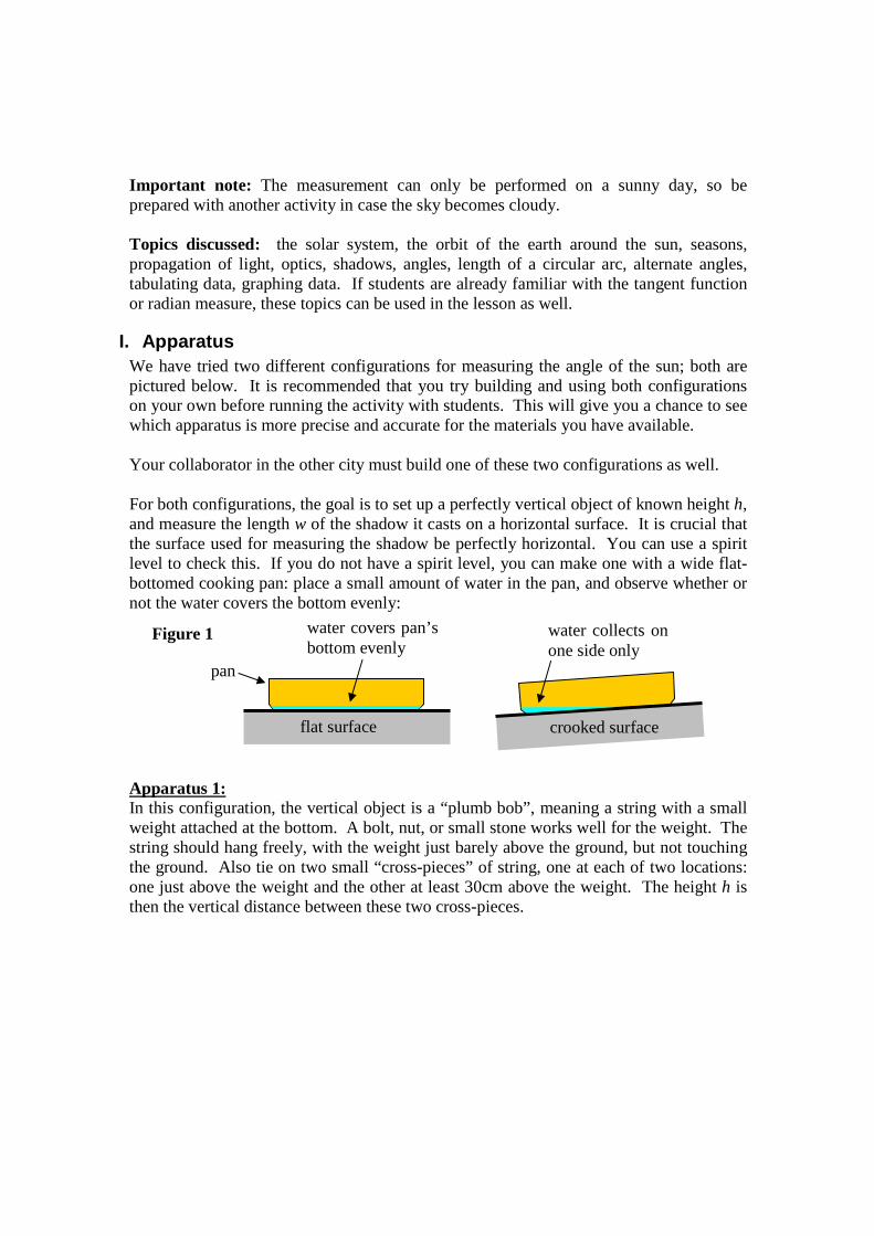
Important note: The measurement can only be performed on a sunny day, so be prepared with another activity in case the sky becomes cloudy. Topics discussed: the solar system, the orbit of the earth around the sun, seasons, propagation of light, optics, shadows, angles, length of a circular arc, alternate angles, tabulating data, graphing data. If students are already familiar with the tangent function or radian measure, these topics can be used in the lesson as well.
I. Apparatus We have tried two different configurations for measuring the angle of the sun; both are pictured below. It is recommended that you try building and using both configurations on your own before running the activity with students. This will give you a chance to see which apparatus is more precise and accurate for the materials you have available. Your collaborator in the other city must build one of these two configurations as well. For both configurations, the goal is to set up a perfectly vertical object of known height h, and measure the length w of the shadow it casts on a horizontal surface. It is crucial that the surface used for measuring the shadow be perfectly horizontal. You can use a spirit level to check this. If you do not have a spirit level, you can make one with a wide flat-bottomed cooking pan: place a small amount of water in the pan, and observe whether or not the water covers the bottom evenly:
Apparatus 1: In this configuration, the vertical object is a “plumb bob”, meaning a string with a small weight attached at the bottom. A bolt, nut, or small stone works well for the weight. The string should hang freely, with the weight just barely above the ground, but not touching the ground. Also tie on two small “cross-pieces” of string, one at each of two locations: one just above the weight and the other at least 30cm above the weight. The height h is then the vertical distance between these two cross-pieces.
flat surface
pan
water covers pan’s bottom evenly
crooked surface
water collects on one side only
Figure 1

You will need to see the shadows of both crosses on the paper:
If the shadow of the lower intersection is obscured by the shadow of the weight, then either use a smaller weight or raise the lower cross piece. If the shadow of the upper intersection is too faint to see, then either lower the top cross piece or use thicker string. To measure the horizontal length w of the shadow, mark the paper at the location of both intersections. The shadow of the upper intersection will be wide and blurry; try to mark its middle. The distance between the two marks can then be measured with a ruler. The bob must not be blown around by the wind. I therefore found it useful to build the apparatus indoors near a window. For times of year when the sun is directly overhead at noon (e.g. January in Zambia), it can be hard to find an indoor location with direct sunlight; in this case you will need to work outdoors. Apparatus 2: In this alternative configuration, the vertical object is a broomstick or other solid pole. A piece of paper is placed on a smooth horizontal surface under the bottom of the pole. The pole is attached by string to four chairs, as shown here:
desk
weight
h
w
Figure 2: Apparatus 1
cross-pieces of string
paper
sunlight
thread
weight
lower cross piece
upper cross piece
vertical string
Draw a mark at centre of both “intersections.” w = distance between these marks
What you will observe on the paper
Where to measure
Figure 3: Shadow cast by apparatus 1

Figure 4
The pole must be exactly vertical; even a slight misalignment will cause large errors in the value we will calculate for the earth radius. To ensure that the pole is vertical, hang two plumb bobs off the sides of the pole:
Adjust the chairs and the pole so that both plumb bobs are aligned with the bottom of the rod. It is not a problem if the pole has a slight bend to it, as long as the bobs hang right next to the bottom of the rod:
Figure 5: Top view of pole
chair
chair
chair
chair
Two plumb bobs placed 90o apart

To measure the length of the shadow w with apparatus 2, first note that the shadow cast by the top of the pole will have a gradual round edge and a larger diameter than the pole itself, as shown in the figure below. Draw a circle of the same radius as the pole, such that the centre of the new circle is the same as the centre of the circular part of the shadow. The value of w you should record is then the distance between the edge of the pole to the corresponding edge of your new circle, as shown in the figure below. (This distance is the same as the distance from the centre of the pole to the centre of the new circle.)
Apparatus 1 has the advantage that you do not need to align anything vertically – gravity automatically keeps the plumb line vertical in this configuration. Apparatus 2 however has the advantage that it is less sensitive to wind. Depending on your materials and location, one apparatus may be preferable to the other.
II. Introduction When the students arrive for the lesson,
• announce that we will be measuring the radius of the earth using shadows. We will do the experiment together with a collaborator in another city.
Figure 6: Side view of pole. (Hopefully your pole is less crooked than the one pictured here!)
Not aligned Not aligned Aligned!
Figure 7: Measuring w with Apparatus 2
What you will observe on the paper Where to measure
pole (viewed from above)
shadow of pole’s top will have fuzzy edge
Draw a circle of same diameter as pole, concentric with the round end of the shadow
w

• Briefly show the students the apparatus. Explain that the length of the shadow cast by the vertical object will tell us something about our orientation relative to the earth and the sun, and that the length of the shadow will be different in different cities.
• Explain that this same experiment was conducted by a man named Eratosthenes around the year 240 B.C. using two cities in Egypt: Aswan and Alexandria.
• Explain that this experiment is remarkable: it shows how a clever measurement can be combined with mathematics to prove something about the world which is much bigger than human scale. You could never measure the radius of the earth directly with a ruler, but we can do so using some clever maths.
• To understand exactly how the length of a shadow depends on which city you are in, we first need to understand the seasons and the motion of the Earth around the Sun.
III. Day and night Show the following demo:
If a globe is not available, you could substitute a ball, perhaps with the continents drawn on it. If the room is dark enough and if the lamp is bright enough, you should be able to tell that the half of the globe facing the lamp is illuminated, whereas the half of the globe facing away from the lamp is dark Have a volunteer hold the globe. Ask the volunteer: “How does the Earth move in one day?” The volunteer should rotate the globe one complete revolution, as shown here:
Make sure the North Pole of the globe is more or less pointed up at the ceiling. If your students are particularly clever, you might want to ask them whether the rotation should be in the direction shown or rather in the opposite direction. The way to tell is to use the
globe
Sun
Figure 9
globe
lamp
Sun
Sign to indicate that the lamp represents the Sun
Figure 8

fact that the Sun appears to rise in the East and set in the West. If the Earth’s rotation was opposite to the direction shown in the figure, then the Sun would appear to rise in the West instead. For most students, however, you can just say that “it turns out that the direction of rotation is this way rather than the opposite way.” Now have the volunteer find your city on the globe. Ask the volunteer: “Which way is the Earth oriented when it is noon here in our city?” The volunteer should rotate the globe so that your city is pointed as directly at the lamp as possible, given that the North Pole still must point up towards the ceiling. For example, if you live in the Southern Hemisphere, the arrangement should look like this:
Now ask the volunteer: “Which way is the Earth oriented when it is midnight here in our city?” The volunteer should rotate the globe so that your city is pointed as directly away from the lamp as possible, again given that the North Pole must point upwards:
Next ask the volunteer: “Which way is the Earth oriented when it is evening and the Sun is setting here in our city?” The volunteer should rotate the globe so that your city is on the boundary of the illuminated and dark regions:
North Pole
Sun Your city at midnight
Figure 11
North Pole
Sun Your city at noon
Figure 10

Switch volunteers so that other students can try out these last few steps.
IV. Seasons Ask your students:
“In our model here, should the North Pole point A) straight up, or B) tilted at an angle?”
Ask if any of the students have an argument for A or B, and allow them to discuss the question with their neighbors. Have your students write down their answers. Now reveal that the correct answer is B. State that one reason we know the axis is tilted is because it explains why there are seasons, as we will see. Now have a volunteer hold the globe, and ask him or her: “Show me how the Earth moves during one year.” Answer:
North Pole
Sun
North Pole
Sun
A) Straight up B) Tilted at an angle
Figure 13
North Pole
Sun Your city at 6pm
Figure 12

It is important that the North Pole keep pointing in the same direction during the “orbit”; in the figure above, for example, the North Pole is always tilted towards the left, meaning it points a bit towards the Sun when the Earth is on the right, and the pole points a bit away from the Sun when the Earth is on the left. The student should spin the globe about the North Pole many times during the orbit, though it doesn’t need to be the real 365 times. Ask the students: “How many times does the Earth spin about the North Pole for every time it travels around the Sun?” Answer: about 365 times, since there are about 365 days in a year. (It’s not exactly 365 though). Now ask the volunteer: “In which part of the orbit is it summer in Johannesburg?” Answer: the part of the orbit for which the North Pole points a bit away from the Sun, because then Johannesburg points almost straight at the sun when it is noon there, and so it is hot. Show the class that at the opposite point in the orbit, when the North Pole points a bit towards the Sun, that Johannesburg never points very directly towards the Sun, and so it is cold there.
Slow yearly orbit
Fast daily spin
Figure 14

Now ask the volunteer: “In which part of the orbit is it summer in London?” Answer: the part of the orbit for which the North Pole points a bit towards the Sun, because then London points almost straight at the sun when it is noon there, and so it is hot. Show the class that at the opposite point in the orbit, when the North Pole points a bit away from the Sun, that London never points very directly towards the Sun, and so it is cold there. If you want, there is much more information which could be covered at this point, such as discussing the Arctic Circle, Tropic of Capricorn and Tropic of Cancer, time zones, latitude and longitude, etc.
V. Shadows First ask your class how the length of the shadow of a vertical object will change during the day. Answer: it is long at sunrise, the length decreases until around midday, then the length increases until the shadow is quite long around sunset. Now ask your class how the direction of the object’s shadow will change during the day. Answer: the shadow will point west at sunrise and it will move towards the east at sunset. At noon it may point north or south depending on your location and the time of year. Next, have a volunteer hold both the globe and one of the matchsticks. Ask the volunteer to orient the match on the globe so as to represent an object which appears vertical in your city. Put another way, point the match the way astronauts would see a flagpole at your school. Answer: the matchstick should have one end on your city, and it should point away from the center of the globe, as shown here:
Johannesburg points away from Sun
London points away from Sun
December: June: London points towards Sun
Johannesburg points towards Sun
Figure 15

If the student initially suggests a different orientation, see if any other students in the class can place the match correctly, and have each student write down his or her vote on which option is correct. Discuss how an object which appears vertical in your city appears sideways when viewing the earth from space. “Up” just means “opposite the direction of gravity,” and gravity pulls towards the centre of the Earth. Next, use sticky tape to fix the match to the globe in the orientation shown above. Show how the match casts a shadow on the globe. It may be helpful to bring the globe closer to the lamp.
Have a volunteer rotate the globe about the North Pole to represent the Earth’s daily rotation. Point out that just after sunrise (when your city crosses into the illuminated region) the match’s shadow is long and it points west. Just before sunset (when your city crosses into the dark region) the match’s shadow is long and it points east. In between, around noon, the shadow length reaches a minimum. Point out that this is exactly the behaviour we described at the start of this section! Now, attach a second matchstick somewhere else on the globe, at a similar longitude but a different latitude to your city (i.e. to the north or to the south of your city.) Demonstrate to the class that the shadows observed in the other city (cast by the second match) differ in both length and direction to the shadows in your city (cast by the original match).
VI. Geometry This next section is fairly mathematical, so it will be suitable for some high school students but not for others. If you feel your students will be confused rather than enlightened by this section, you may skip to section VIII, first writing down the procedure summarized in section VII without explaining in detail where these steps come
North Pole
Sun
Your city
shadow of match
Figure 17
Your city
matchstick
Figure 16

from. For example, you could tell your students “It turns out that if you work through some geometry, you can show that the radius of the Earth can be calculated using these steps…” If you decide to proceed with this section, first state that you can think of light as coming out of a source in parallel rays, and that shadows appear wherever the rays are blocked by the match. Draw the following figure on the chalkboard:
When the light source is nearby, the rays travel in noticeably different directions. However, as the light source gets very far away from the object casting the shadow, then the rays become almost parallel. They are never exactly parallel, but to a good approximation we can pretend that they are exactly parallel:
Since the Sun is so far away from us, then it is a good approximation to think of the rays from the Sun as being parallel to each other. Next, suppose it is December 21, so the Earth’s axis of rotation points away from the Sun. Also suppose that our city is far enough north that shadows point north on this day of the year:
ground
matchstick
rays of light
nearby light source
shadow
Figure 18
ground
rays of light from distant source
shadow matchstick
Figure 19

On other days of the year, the picture is more complicated, because when our city points towards the sun (i.e. at the time of minimum shadow length), the rotation axis would point out of the page or into the page. Only on the solstices (December 21 and June 21) does the rotation axis lie in the same plane, making the geometry much easier. It takes some sophisticated mathematics (differentiation and multiplication of rotation matrices) to show that the equations we will find in this section are actually true on any day of the year, not just on the solstices. (The details are given in Appendix A, but they are complicated, so don’t worry if you don’t have time to read this appendix.) For simplicity, however, we can just analyze the December 21 situation here. Next we’ll need to analyze the geometry of the situation. The figure below is a close-up of the previous figure, and I have labeled several of the lengths and angles:
w = minimum length of shadow h = height of a vertical object (pole, or distance between cross-strings on plumb bob) a = the angle between the sun and your city, with vertex at the centre of the Earth b = minimum angle of a shadow at your city Ask the students the following multiple-choice question:
A) angle a is bigger than angle b, B) a < b C) a = b D) it depends on which city you are in
our city
vertical object at our school
Earth’s rotation axis
to Sun
rays of sunlight
Figure 20
b
a
w h
centre of Earth
to Sun
to Sun
rays of sunlight Earth
shadow
Figure 21
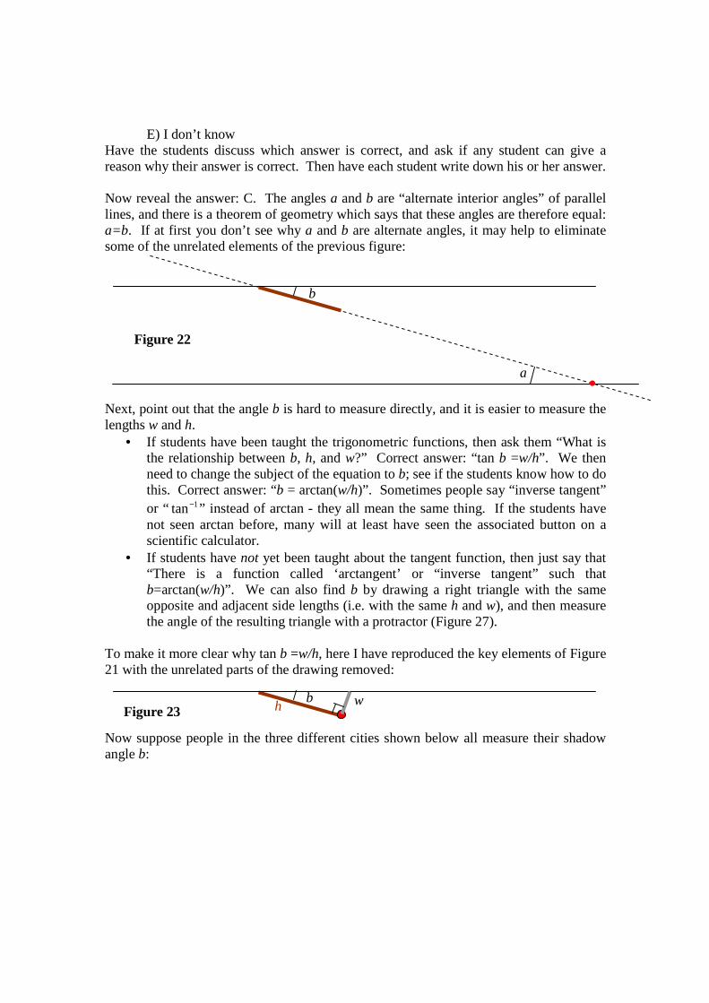
E) I don’t know Have the students discuss which answer is correct, and ask if any student can give a reason why their answer is correct. Then have each student write down his or her answer. Now reveal the answer: C. The angles a and b are “alternate interior angles” of parallel lines, and there is a theorem of geometry which says that these angles are therefore equal: a=b. If at first you don’t see why a and b are alternate angles, it may help to eliminate some of the unrelated elements of the previous figure:
Next, point out that the angle b is hard to measure directly, and it is easier to measure the lengths w and h.
• If students have been taught the trigonometric functions, then ask them “What is the relationship between b, h, and w?” Correct answer: “tan b =w/h”. We then need to change the subject of the equation to b; see if the students know how to do this. Correct answer: “b = arctan(w/h)”. Sometimes people say “inverse tangent” or “ 1tan− ” instead of arctan - they all mean the same thing. If the students have not seen arctan before, many will at least have seen the associated button on a scientific calculator.
• If students have not yet been taught about the tangent function, then just say that “There is a function called ‘arctangent’ or “inverse tangent” such that b=arctan(w/h)”. We can also find b by drawing a right triangle with the same opposite and adjacent side lengths (i.e. with the same h and w), and then measure the angle of the resulting triangle with a protractor (Figure 27).
To make it more clear why tan b =w/h, here I have reproduced the key elements of Figure 21 with the unrelated parts of the drawing removed:
Now suppose people in the three different cities shown below all measure their shadow angle b:
b w h Figure 23
b
a
Figure 22

So the person in City 1 measures a shadow angle 1b , the person in City 2 measures a
shadow angle 2b , etc. Notice that the people in cities 1 and 2 see the shadow point north, whereas the person in city 3 sees the shadow point south. Now, define the angles f and g as follows:
Give your students this multiple-choice question: A) 21 bbf += and 32 bbg +=
B) 21 bbf −= and 32 bbg +=
C) 21 bbf += and 32 bbg −=
D) 21 bbf −= and 32 bbg −= E) I don’t know Ask if any of the students have an argument to support one of the options. Allow the students to discuss the question with their neighbors. Have your students write down
city 1
Figure 25
city 3
city 2
Earth’s rotation axis
f
g
Er
Er
distance d
city 1
to Sun
rays of sunlight
Figure 24
city 3
city 2 1b
2b
3b
Earth’s rotation axis
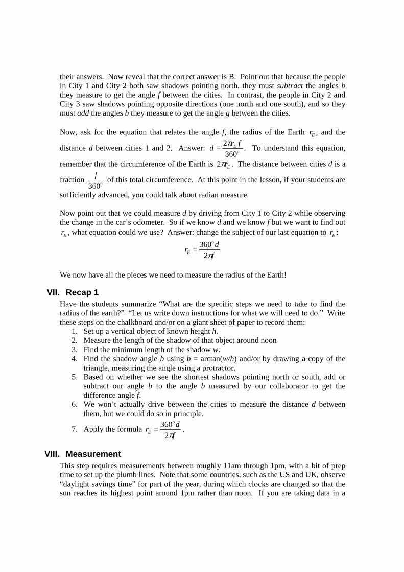
their answers. Now reveal that the correct answer is B. Point out that because the people in City 1 and City 2 both saw shadows pointing north, they must subtract the angles b they measure to get the angle f between the cities. In contrast, the people in City 2 and City 3 saw shadows pointing opposite directions (one north and one south), and so they must add the angles b they measure to get the angle g between the cities. Now, ask for the equation that relates the angle f, the radius of the Earth Er , and the
distance d between cities 1 and 2. Answer: o360
2 frd Eπ= . To understand this equation,
remember that the circumference of the Earth is Erπ2 . The distance between cities d is a
fraction o360
f of this total circumference. At this point in the lesson, if your students are
sufficiently advanced, you could talk about radian measure. Now point out that we could measure d by driving from City 1 to City 2 while observing the change in the car’s odometer. So if we know d and we know f but we want to find out
Er , what equation could we use? Answer: change the subject of our last equation to Er :
f
drE π2
360o
=
We now have all the pieces we need to measure the radius of the Earth!
VII. Recap 1 Have the students summarize “What are the specific steps we need to take to find the radius of the earth?” “Let us write down instructions for what we will need to do.” Write these steps on the chalkboard and/or on a giant sheet of paper to record them:
1. Set up a vertical object of known height h. 2. Measure the length of the shadow of that object around noon 3. Find the minimum length of the shadow w. 4. Find the shadow angle b using b = arctan(w/h) and/or by drawing a copy of the
triangle, measuring the angle using a protractor. 5. Based on whether we see the shortest shadows pointing north or south, add or
subtract our angle b to the angle b measured by our collaborator to get the difference angle f.
6. We won’t actually drive between the cities to measure the distance d between them, but we could do so in principle.
7. Apply the formula f
drE π2
360o
= .
VIII. Measurement This step requires measurements between roughly 11am through 1pm, with a bit of prep time to set up the plumb lines. Note that some countries, such as the US and UK, observe “daylight savings time” for part of the year, during which clocks are changed so that the sun reaches its highest point around 1pm rather than noon. If you are taking data in a

country which is observing daylight savings time, you should therefore record measurements between noon and 2pm instead of between 11am-1pm. Your collaborator in the other city will need to make the same set of measurements as you. It is ideal if your collaborator can take measurements on the same day as you, or within a few days of you at most. If your collaborator makes his or her measurements several days before or after you, the motion of the Earth around the Sun during that time will introduce an error1. The error is smaller if you and your collaborator are further away from each other. For cities within 300km, such as Lusaka – Livingstone, the measurements should be no more than a couple days apart. For greater distances, such as Lusaka – Nairobi, even a week between the measurements will not introduce much error. Every 10 minutes or so, have a student measure the shadow length w as described in figures 3 and 7. It is not crucial if the intervals are not exactly 10 minutes long. It is also no problem if you miss a few measurements due to clouds. Make a table to record the data:
Time Minutes past 11:00am Shadow length w (cm) 11:02 2 15.0 11:13 13 12.2 11:22 22 10.1 11:34 34 8.4
… Also, around the time that the shadow length seems to be at its shortest, record whether the shadow points roughly north or roughly south. Now graph the data, with “minutes past 11:00” as the x-axis, and “w” as the y-axis. The values of w you record should decrease to a minimum and then increase again. After the last data point is recorded, draw a smooth “best-fit” curve - a curve which is as smooth as possible while passing as close as possible to all the data points:
1 In the terminology of Appendix A, the angle u changes slightly each day, and if the delay between the two measurements is too long, the change in u will grow comparable to the difference in latitudes between the two cities which you are trying to measure.
minutes past 11am
w (cm)
0 20 40 60 80 120 4
8
10
12
16
14
Figure 26 (You will obtain different values of w.)
100

You will find that some data points lie slightly above the best-fit curve while other points fall below the curve. Discuss this observation with the class: “Does this occur because the sun moves in a jerky manner? If not, what other factors cause some points to seem ‘too high’ or ‘too low’?” Answer: human error and uncertainty in making the measurement, small movements of the apparatus due to wind, etc. Now read the minimum of the best-fit curve. (For the data in the previous figure, this minimum w would be roughly 4.7 cm.) I will call this number minw . Next, we will need to convert h and minw to an angle. (Remember, h is the distance between the cross-strings if you are using apparatus 1, or the height of the pole if you are using apparatus 2.) If the students are not familiar with the tangent function, then draw a right triangle on a big flat rectangular object, using the corner of the rectangular object as the right angle, and such that the sides of the triangle that touch the right angle have length h and minw :
It is important that the hypotenuse be very straight, so use the edge of a straight object such as a metre stick to draw it. Now measure the angle against side h with a protractor - this will give you b. Next, whether or not the students have seen the arctangent function before, have them compute ( )minarctan /w h using a calculator. If you drew a copy of the triangle as in
Figure 27, you should get the same answer. For the remainder of the calculation, use the value of b obtained with a calculator rather than the one measured with the protractor, since the former method is more precise than the latter. At this point we will need the value of b obtained by the collaborator in the other city. We also need to know whether the collaborator observed the minimum shadow to point north or south. If both you and collaborator observed shadows pointing north, or if you both observed shadows pointing south, then subtract the values of b. (Subtract the smaller one from the larger one so you get a positive answer). On the other hand, if you observed a shadow pointing south while the collaborator observed a shadow pointing north, or vice-versa, then add the values of b you obtained. Whether you add or subtract, call the resulting angle f.
Figure 27 flat rectangular object
h
minw
b
protractor

You will now need the distance d between you and your collaborator. Several values are given in Appendix B. If you are using a pair of cities other than the ones in the appendix, you will need to look up the distance d on a map, as shown in the figure below. Remember that it is only the north-south component of the distance which matters, since any east-west distance between the cities causes the shadow lengths to reach a minimum at different times, not different lengths. The distance d is generally less than the total distance between the cities:
Finally, compute f
drE π2
360o
= . Compare the result you obtain to the actual Earth radius =
6370km. Discuss/brainstorm why our result is slightly different.
IX. Recap 2 Ask the students “What were some of the key ideas we learned and used in this lesson?” Write the responses on the board. Emphasize:
- The model of an Earth spinning on an axis at an angle is very successful. It explains many things, such as why there are seasons and why shadows change during the day as they do.
- A clever measurement can be combined with mathematics to prove something about the world which is much bigger than human scale.
- Ideas from mathematics, such as the tangent function, alternate angles, (and radian measure if you discuss it) can be useful for something!
Appendix A: Relationship between your latitude and the minimum shadow angle you measure, for any day of the year You do not need to understand the mathematics in this section in order to give the lesson; I wrote up this appendix to rigorously analyze how the minimum shadow angle you observe will depend on your latitude on days other than the solstices. This section is definitely too advanced for secondary students. The key finding is that the experiment can be done on any day of the year.
Figure 28
North
Map
City 1
City 2
d is the distance measured this way…
… not the total distance measured this way.

To analyze the geometry of shadows, I will use two different points of view. In the first system, let us introduce (x, y, z) coordinates, taking the origin to be at the center of the Earth, with the z-axis directed towards the sun, and the x-axis pointed along the plane of the earth’s orbit:
Now let me introduce the other point of view: a “sidereal reference frame.” Here, we imagine that we are looking at the solar system from a space ship, which is positioned such that neither the Sun nor distant stars appear to move relative to us during the course of one Earth-year, and rotated so that we look down on the Earth’s orbit (and so the Earth is always the same distance from us). Any space ship just outside the solar system could be maneuvered so these conditions would all be true: the astronauts aboard could fire their engines to rotate their ship until the relative motion of distant stars disappeared. Then, if the astronauts saw the Sun moving closer or further away, they could fire the engines to accelerate such that the ship stopped moving relative to the Sun. (Assume you are far enough from the Sun that you can neglect its gravitational force on you. Also, the distant stars will move relative to each other, but only very slowly, and so you can ignore the tiny change that occurs during 1 year). This sidereal frame is important because the Earth’s rotation axis will always point in the same direction in this frame. (In the x,y,z frame this rotation axis changes, sometimes pointing a bit towards x, sometimes a bit towards z, etc.)
Sun
Earth
x
y z
Earth’s yearly rotation
Top view Figure 30
Sun
Earth
x
y
z
Earth’s yearly rotation
Side view Figure 29

Now, let q represent the angle of the Sun-to-Earth vector in our sidereal frame, so q increases by o360 in one year. Suppose q=0 corresponds to the summer solstice, q= o90 corresponds to the autumnal equinox, etc. Also, let s denote the angle of the Earth’s rotation about its own axis as viewed from our sidereal frame. Suppose we are in a city which experiences noon at s=0. One day later, i.e. the next time we experience noon, the angle s will have increased by a little more than o360 , because q will have increased slightly during that time. (It turns out that s increases by o360 every 0.99727 days.)
Next, let t be the tilt of the earth’s rotation axis (i.e. the North Pole) relative to the ye
direction: t has been measured to be o4.23 . Finally, let l represent the latitude of our city (or any point which is fixed with respect to the ground), with 0=l corresponding to the equator and o90=l corresponding to the North Pole. Then if you think through the geometry, it turns out that the position vector ( )zyx ,,=r of our city can be found by
multiplying the ze vector by four matrices and then by the radius of the Earth Er :
( ) ( ) ( ) ( ) zxyxyE RsRtRqRr er l−−= ( 1 )
Here, ( )vRi is the matrix for rotation by angle v about the coordinate axis i. The signs of
the rotation have been chosen to match the Earth’s true motion if q and s are understood to increase in time. Next, rotate Figure 30 about the z axis until your city (i.e. the position vector r ) lies in the plane of the paper. You can convince yourself that the shadow of a vertical object in the city will then lie in the plane of the paper as well:
Sun q
Earth’s yearly rotation
Sidereal point of view
s
some city
June 21, noon
June 21, 9pm
June 22, noon
North Pole
s
Figure 31

Thus, the angle b that the shadow makes with respect to your local zenith (the “zenith” is the direction which appears vertical in your city) is the same as the angle b between the position vector r and the unit vector that points towards the sun ze . Since r was constructed by applying (unitary) rotation matrices to a unit vector and then multiplying by the Earth radis Er , then the length of the vector r is Er=r . Consequently,
brj E cos= ( 2 )
It follows that the maximum and minimum shadow angles occur at the same time of day as the maxima and minima of j. In the rest of this section I will use the word “extremum” to mean “either maximum or minimum.” We next need to compute j from ( 1 ):
( )
[ ][ ]{ }sqstqtqr
ss
ss
tt
tt
r
j
E
E
z
sin sincos cos coscossin sin cos
1
0
0
cossin0
sincos0
001
cos0sin
010
sin0cos
cossin0
sincos0
001
cos0sin
010
sin0cos
100
++=
−
−
−
−=
⋅=
ll
ll
ll
re
( 3 )
To a good approximation, we can take q to be constant during the relatively rapid increase in s over a day, and so the condition of extremum shadow length is obtained by setting
[ ][ ]
t
qs
qstqsrds
djE
cos
tantan so
cos sin cossin coscos0
=
−== l
( 4 )
We next want to express the value of the extremum shadow angle b as a function of q, t, and l by eliminating s in ( 3 ). As a first step we must recognize that there are two possible angles s that satisfy ( 4 ); these two angles differ by o180 . (The fact that there are two solutions corresponds to the fact that each day the sun reaches both a maximum angle above the horizon and also a maximum angle below the horizon.) I will name these two possible values 1s and 2s . To use ( 3 ) we will need to find cos s and sin s, and since
there are two possible values for s, there are two possible values for its sine and cosine,
Earth
r
shadow
b
b vertical object
city
j z direction
Figure 32

which differ by a minus sign. Using the equations 2 2sin cos 1s s+ = and tan sin / coss s s= we find
1 12 2
2 22 2
tan 1sin , cos
1 tan 1 tantan 1
sin , cos1 tan 1 tan
ss s
s ss
s ss s
= + = ++ +
= − = −+ +
( 5 )
Substituting in ( 4 ) we obtain
1 12 2 2 2
2 22 2 2 2
tan cossin , cos
cos tan cos tan
tan cossin , cos
cos tan cos tan
q ts s
t q t q
q ts s
t q t q
= + = ++ +
= − = −+ +
( 6 )
(If you are worried about the signs, remember that cos t >0). We then substitute these expressions into ( 3 ) and apply the formula for the extremum shadow angles ( 2 ). The two solutions for s give two solutions for b:
2
1 2 2 2 2
2
2 2 2 2 2
cos cos sin tanarccos cos sin sin cos
cos tan cos tan
cos cos sin tanarccos cos sin sin cos
cos tan cos tan
q t q qb q t
t q t q
q t q qb q t
t q t q
= + + + +
= − + + +
l l
l l
( 7 )
After some algebra, these solutions can be written
[ ]( )[ ]( )
2 2 21
2 2 22
arccos cos sin sin cos cos cos sin
arccos cos sin sin cos cos cos sin
b q t t q q
b q t t q q
= + +
= − +
l l
l l
( 8 )
(The two b’s in ( 8 ) may actually be swapped compared to the two b’s in ( 7 ) depending on the sign of cos q). Introduce a new angle u defined by
( )qtu cos sinarcsin= ( 9 )
with the usual choice of range for arcsin: oo 9090 <<− u . Then it follows that
2 2 2 2 2sin sin cos , cos 1 sin cos cos cos sinu t q u t q t q q= = − = + ( 10 )
and so our two solutions for the extremum angles can be written
( )( )( )
1 arccos sin sin cos cos
arccos cos
b u u
u
u
= +
= −
= −
l l
l
l
( )( )( )
2
o
arccos sin sin cos cos
arccos cos
180
b u u
u
u
= −
= − +
= − +
l l
l
l
( 11 )

Now assume that neither you nor you collaborator are above the Arctic Circle or below the Antarctic Circle. These circles are defined by the latitudes t−o90 and t+− o90 respectively, so our assumption means that t−< o90l and t+−> o90l . From ( 9 ) it can be seen that tu ≤ and tu −≥ , and so u−< o90l and u+−> o90l . It follows that
o2 90>b , corresponding to the uninteresting case of an extremum during the night (when
the Sun reaches its maximum angle below the horizon, which you can’t see). Therefore the minimum shadow angle is given by
ub −= l . ( 12 )
At the latitude u=l , observers will see shadows shrink to zero length during the day. If you are north of this latitude, you will see shadows cast in a northerly direction, and if you are south of latitude u, shadows will point in a southerly direction.
Finally, let ub yy −= l represent the shadow angle measured by you, and let ub cc −= l
represent the shadow angle measured by your collaborator. There are four possible cases to consider: Case 1: Both you and your collaborator see shadows pointing north. Therefore uy >l
and uc >l . Therefore ub yy −= l and ub cc −= l . Subtracting these last two equations,
we obtain cycy bb −=− ll . This means the difference in shadow angles is the difference
in your latitudes. Case 2: Both you and your collaborator see shadows pointing south. Therefore uy <l
and uc <l . Therefore ub yy +−= l and ub cc +−= l . Subtracting these last two
equations, we obtain yccy bb −=− ll . This means the difference in shadow angles is the
difference in your latitudes. Case 3: You observe shadows pointing south whereas your collaborator sees shadows pointing north. Therefore uy <l and uc >l . Therefore ub yy +−= l and ub cc −= l .
Adding these last two equations, we obtain cyyc bb +=− ll . This means the difference
in your latitudes is the sum of your shadow angles. Case 4: You observe shadows pointing north whereas your collaborator sees shadows pointing south. Therefore uy >l and uc <l . Therefore ub yy −= l and ub cc +−= l .
Adding these last two equations, we obtain cycy bb +=− ll . This means the difference
in your latitudes is the sum of your shadow angles. Thus, we have proven our key result: if we measure the minimum shadow angles at two latitudes, and add or subtract these angles appropriately, we obtain precisely the difference in latitudes, regardless of which day of the year it is.

Interestingly, on the days of the equinoxes ( o90q = or o270q = ), u becomes 0, equation
( 11 ) then reduces to l=b , and so you can measure your latitude directly by measuring
the shadow angle.
Appendix B: Useful numbers Tilt of Earth’s rotation axis relative to the plane of its orbit: o4.23=t Latitude l of Lusaka = − 15.417 o Latitude l of Livingstone =− 17.855o Latitude l of Ndola = − 12.968o Latitude l of Kitwe = − 12.807o Latitude l of Nairobi = − 1.283o Latitude l of Cape Town = − 33.917o Latitude l of Johannesburg = − 26.167o Distance d: the north-south component of the distance between two cities:
Between Lusaka & Livingstone: d = 271 km. Between Lusaka & Ndola: d = 272 km. Between Lusaka & Kitwe: d = 290 km. Between Lusaka & Nairobi: d = 1571 km. Between Lusaka & Cape Town: d = 2057 km. Between Lusaka & Johannesburg: d = 1195 km.
Actual Earth radius = 6,370 km