Measuring Instruments - BS Publications
98
CHAPTER 1 Measuring Instruments 1.1 Introduction The fundamental quantities of electrical engineering such as current, voltage, power, energy, power factor and frequency have to be measured with the help of instruments for the purpose of computing the system efficiency and stability. The instruments which are designed to measure these quantities are called measuring instruments. The size and capacity of the instrument vary depending on the magnitude of measurement but the basic working principle is the same. 1.2 Classification of Measuring Instruments Measuring instruments are classified as: 1.2.1 Absolute Instruments These are those which give the quantity to be measured in terms of instrument constant and its deflection and requires no comparison with any others standard instruments. Example: Tangent galvanometer and Rayleigh’s current balance. 1
Transcript of Measuring Instruments - BS Publications
CHAPTER 1
Measuring Instruments
1.1 Introduction
The fundamental quantities of electrical engineering such as current, voltage, power, energy, power factor and frequency have to be measured with the help of instruments for the purpose of computing the system efficiency and stability. The instruments which are designed to measure these quantities are called measuring instruments. The size and capacity of the instrument vary depending on the magnitude of measurement but the basic working principle is the same.
1.2 Classification of Measuring Instruments
Measuring instruments are classified as:
1.2.1 Absolute Instruments
These are those which give the quantity to be measured in terms of instrument constant and its deflection and requires no comparison with any others standard instruments.
Example: Tangent galvanometer and Rayleigh’s current balance.
1
2 Electrical and Electronic Measurements and Instrumentation 1.2.2 Secondary Instruments
These are the instruments which give directly the value of the quantity being measured by the amount of deflection which is pre-calibrated by comparison with absolute instruments or one which has already been calibrated. Such instruments are designed to serve mainly the three purposes.
1. Indicate the instantaneous value being measured and record it.
2. Indicate the instantaneous value of the quantities being measured.
3. Measure the different quantities and integrate to give a unstable result.
1.2.2.1 Indicating Instruments
These are the instruments which indicate the magnitude of the instantaneous values being measured by means of pointer over a calibrated scale.
The indication of pointer also change with respect to time.
Example: Ammeter, voltmeter, wattmeter, frequency meter, power factor meter etc.
1.2.2.2 Recording Instruments
These instruments not only read the instantaneous values but also record continuously the magnitude of the quantity on a paper over a period of time.
The moving system of the instrument carries an inked pen (pointer) which rest lightly on a graph or chart. That is moved at a low speed and uniform, in a direction perpendicular to that of the deflection of the pointer.
These instruments are generally used in power house.
1.2.2.3 Integrating Instruments
These are measure the total quantity of electricity detected over a period of a time.
Example: Energy meter (Ampere-hour and watt-hour meters) etc.
1.3 Essentials of Indicating Instruments
In most of the indicating instruments three distinct torque are required for operation. They are:
1. Deflecting torque Td (or) deflection system
2. Controlling torque Tc (or) control system
3. Damping torque (or) damping system
The above systems use one of the following effect, produced by current (or) voltage, produce deflecting torque.
Measuring Instruments 3
1. Thermal effect: The current to be measured is passed through small element which heats it. The temperature converted into e.m.f using thermocouple producing current again.
2. Induction effect: Eddy currents are produced due to magnetic flux (alternating). This producers force to move non magnetic disc. Induction principle is used for AC quantities.
3. Magnetic effect: Force is developed when current carrying conductor placed in magnetic field force. F = BIL.
4. Electrostatic effect: When two plates are charged, electrostatic forces are developed. This force is used to displace one plate. The displacement is directly proportional to the voltage which displacement is calibrated to magnitude of voltage
Suitable for voltmeters only.
1.4 Deflecting System
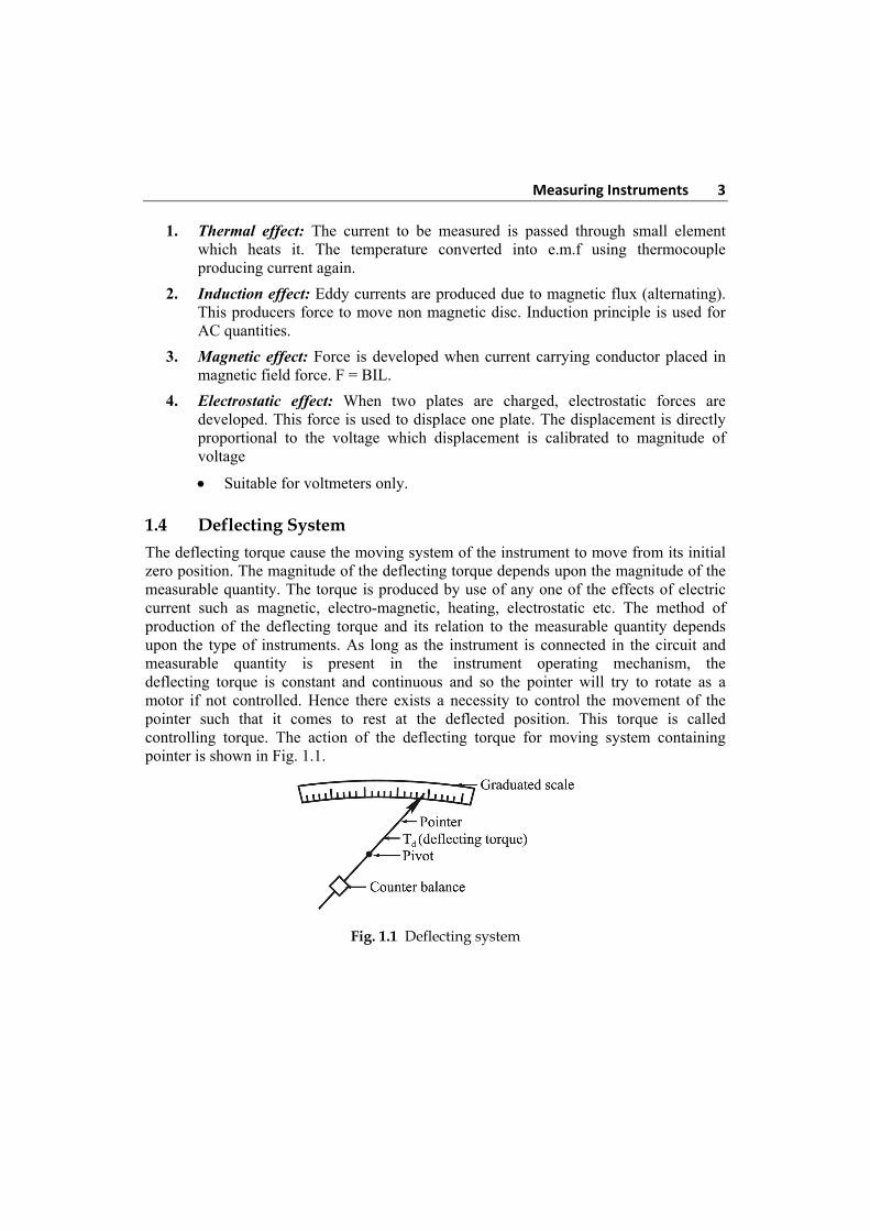
The deflecting torque cause the moving system of the instrument to move from its initial zero position. The magnitude of the deflecting torque depends upon the magnitude of the measurable quantity. The torque is produced by use of any one of the effects of electric current such as magnetic, electro-magnetic, heating, electrostatic etc. The method of production of the deflecting torque and its relation to the measurable quantity depends upon the type of instruments. As long as the instrument is connected in the circuit and measurable quantity is present in the instrument operating mechanism, the deflecting torque is constant and continuous and so the pointer will try to rotate as a motor if not controlled. Hence there exists a necessity to control the movement of the pointer such that it comes to rest at the deflected position. This torque is called controlling torque. The action of the deflecting torque for moving system containing pointer is shown in Fig. 1.1.
Fig. 1.1 Deflecting system
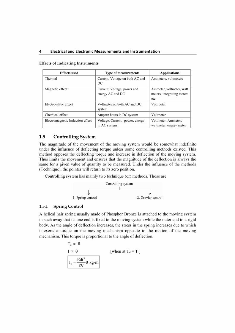
4 Electrical and Electronic Measurements and Instrumentation Effects of indicating Instruments
Effects used Type of measurements Applications
Thermal Current, Voltage on both AC and DC
Ammeters, voltmeters
Magnetic effect Current, Voltage, power and energy AC and DC
Ammeter, voltmeter, watt meters, integrating meters etc.
Electro-static effect Voltmeter on both AC and DC system
Voltmeter
Chemical effect Ampere hours in DC system Voltmeter
Electromagnetic Induction effect Voltage, Current, power, energy, in AC system
Voltmeter, Ammeter, wattmeter, energy meter
1.5 Controlling System
The magnitude of the movement of the moving system would be somewhat indefinite under the influence of deflecting torque unless some controlling methods existed. This method opposes the deflecting torque and increase in deflection of the moving system. Thus limits the movement and ensures that the magnitude of the deflection is always the same for a given value of quantity to be measured. Under the influence of the methods (Technique), the pointer will return to its zero position.
Controlling system has mainly two technique (or) methods. Those are
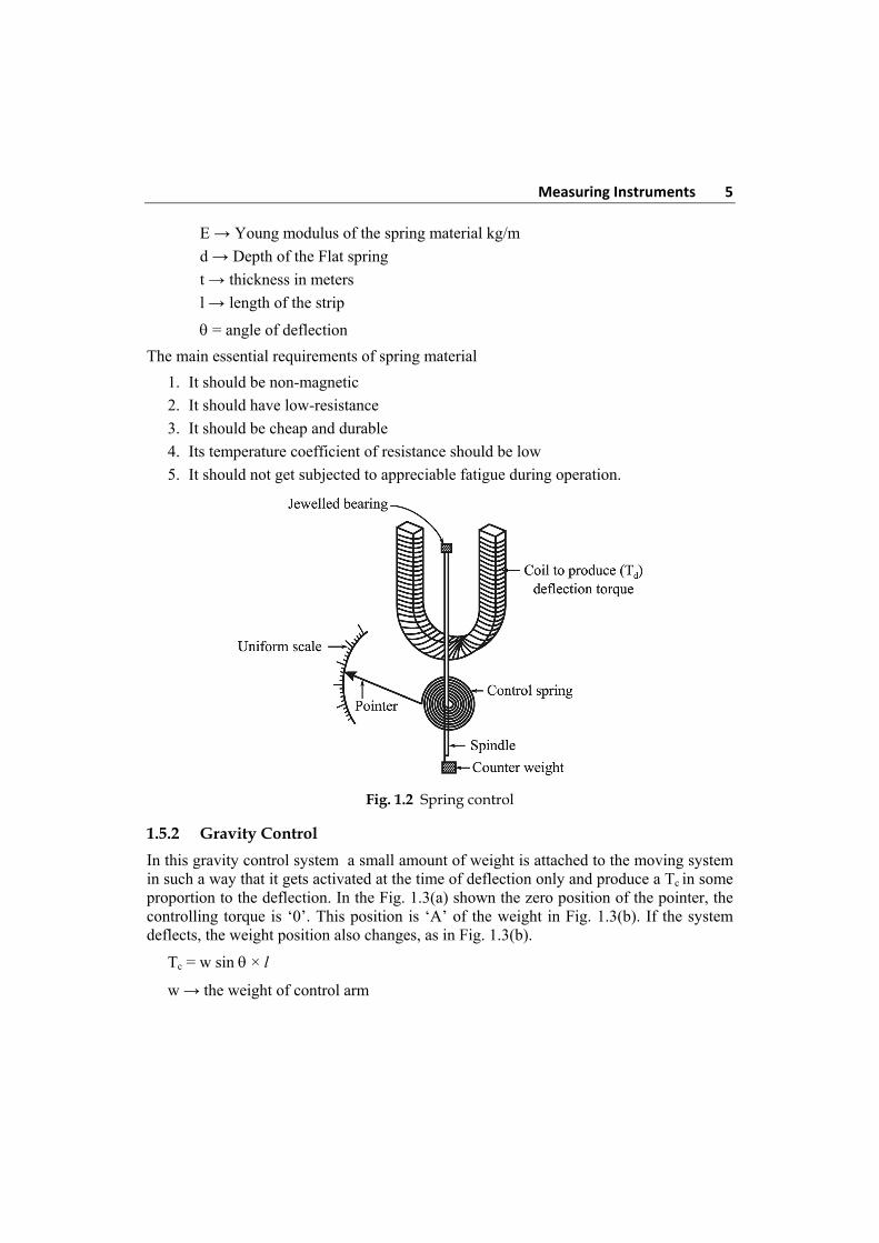
1.5.1 Spring Control
A helical hair spring usually made of Phosphor Bronze is attached to the moving system in such away that its one end is fixed to the moving system while the outer end to a rigid body. As the angle of deflection increases, the stress in the spring increases due to which it exerts a torque on the moving mechanism opposite to the motion of the moving mechanism. This torque is proportional to the angle of deflection.
Tc
I [when at Td = Tc]
3
c
EdtT kg-m
i2
l
Measuring Instruments 5
E → Young modulus of the spring material kg/m
d → Depth of the Flat spring
t → thickness in meters
l → length of the strip
= angle of deflection
The main essential requirements of spring material
1. It should be non-magnetic
2. It should have low-resistance
3. It should be cheap and durable
4. Its temperature coefficient of resistance should be low
5. It should not get subjected to appreciable fatigue during operation.
Fig. 1.2 Spring control
1.5.2 Gravity Control
In this gravity control system a small amount of weight is attached to the moving system in such a way that it gets activated at the time of deflection only and produce a Tc in some proportion to the deflection. In the Fig. 1.3(a) shown the zero position of the pointer, the controlling torque is ‘0’. This position is ‘A’ of the weight in Fig. 1.3(b). If the system deflects, the weight position also changes, as in Fig. 1.3(b).
Tc = w sin × l
w → the weight of control arm
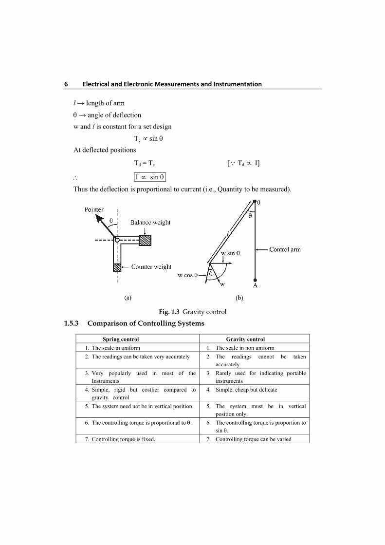
6 Electrical and Electronic Measurements and Instrumentation l → length of arm
→ angle of deflection
w and l is constant for a set design
Tc sin
At deflected positions
Td = Tc [ Td I]
I sin
Thus the deflection is proportional to current (i.e., Quantity to be measured).
Fig. 1.3 Gravity control
1.5.3 Comparison of Controlling Systems
Spring control Gravity control
1. The scale in uniform 1. The scale in non uniform
2. The readings can be taken very accurately 2. The readings cannot be taken accurately
3. Very popularly used in most of the Instruments
3. Rarely used for indicating portable instruments
4. Simple, rigid but costlier compared to gravity control
4. Simple, cheap but delicate
5. The system need not be in vertical position 5. The system must be in vertical position only.
6. The controlling torque is proportional to . 6. The controlling torque is proportion to sin .
7. Controlling torque is fixed. 7. Controlling torque can be varied
Measuring Instruments 7
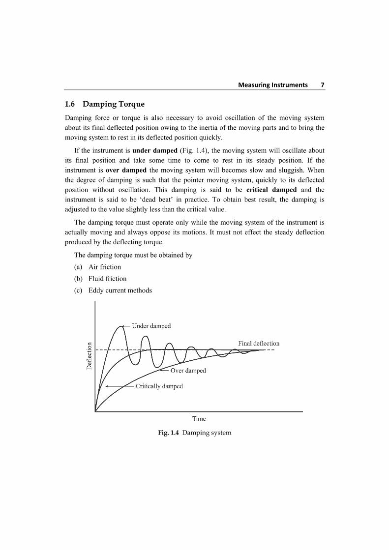
1.6 Damping Torque
Damping force or torque is also necessary to avoid oscillation of the moving system about its final deflected position owing to the inertia of the moving parts and to bring the moving system to rest in its deflected position quickly.
If the instrument is under damped (Fig. 1.4), the moving system will oscillate about its final position and take some time to come to rest in its steady position. If the instrument is over damped the moving system will becomes slow and sluggish. When the degree of damping is such that the pointer moving system, quickly to its deflected position without oscillation. This damping is said to be critical damped and the instrument is said to be ‘dead beat’ in practice. To obtain best result, the damping is adjusted to the value slightly less than the critical value.
The damping torque must operate only while the moving system of the instrument is actually moving and always oppose its motions. It must not effect the steady deflection produced by the deflecting torque.
The damping torque must be obtained by
(a) Air friction
(b) Fluid friction
(c) Eddy current methods
Fig. 1.4 Damping system
8 Electrical and Electronic Measurements and Instrumentation 1.6.1 Air Friction Damping
This method uses a light aluminium piston to the moving system shown in Fig. 1.5. The piston moves inside the air chamber with least clearance along with the movement of the pointer. The clearance between the piston and sides of the chamber is kept least and uniform. As the piston moves inside the chamber rapidly, the air inside the closed space is compressed and the pressure so developed opposes the motion of the piston. If the piston moves out of the chamber rapidly the pressure in the closed space decrease than normal and the pressure on the open side of the piston would be greater than that of the opposite side. In the process of equilising the pressure motion of the piston is again opposed. The only care that must be taken for efficient damping is that the arm carrying the piston is not bent or the piston does not touch the walls of the chamber else it would lead to serious error in reading.
Fig. 1.5 Air friction damping
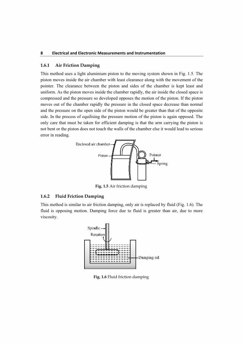
1.6.2 Fluid Friction Damping
This method is similar to air friction damping, only air is replaced by fluid (Fig. 1.6). The fluid is opposing motion. Damping force due to fluid is greater than air, due to more viscosity.
Fig. 1.6 Fluid friction damping
Measuring Instruments 9
Disadvantage of fluid damping
1. The instrument has to be used only in vertical position.
2. Oil creeps out if the sealing is not perfect.
1.6.3 Eddy Current Damping
This method is mainly based on Faraday’s law and Lenz’s law. When a conductor moves in magnetic field cut’s the flux, emf induced in it and direction of this emf is to oppose the cause producing it. This current interacts with the magnetic field to produce an electromagnetic torque which opposes the motion. This torque is proportional to the strength of the magnetic field and the ‘current’ produced. The current is proportional to emf which in turn is proportional to velocity of the conductor. Thus if the strength of the magnetic field is constant, the torque is proportional to velocity of the conductor. This method is the most effective.
1.7 Permanent Magnet Moving Coil (PMMC)
These instruments are universally used for DC measurements. The basic working principle of a PMMC instrument is the same at that D’ Arsonval Galvanometer but it slightly differs from the D’ Arsonval Galvanometer in construction.
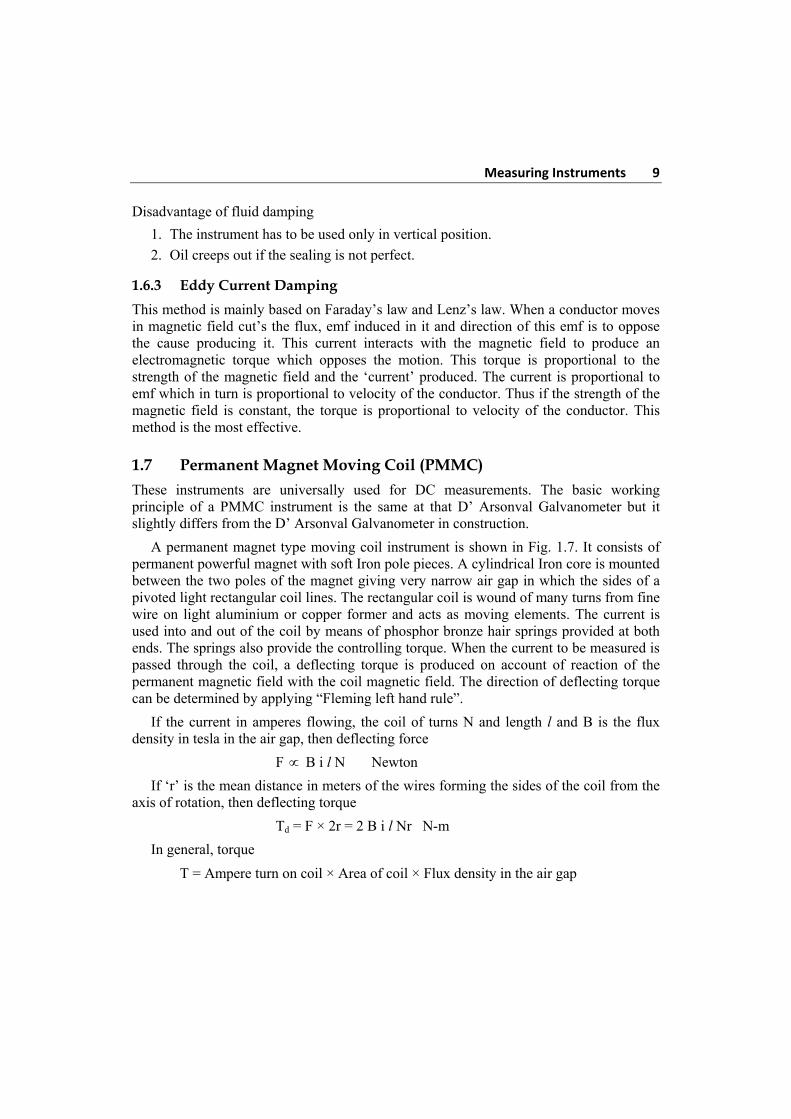
A permanent magnet type moving coil instrument is shown in Fig. 1.7. It consists of permanent powerful magnet with soft Iron pole pieces. A cylindrical Iron core is mounted between the two poles of the magnet giving very narrow air gap in which the sides of a pivoted light rectangular coil lines. The rectangular coil is wound of many turns from fine wire on light aluminium or copper former and acts as moving elements. The current is used into and out of the coil by means of phosphor bronze hair springs provided at both ends. The springs also provide the controlling torque. When the current to be measured is passed through the coil, a deflecting torque is produced on account of reaction of the permanent magnetic field with the coil magnetic field. The direction of deflecting torque can be determined by applying “Fleming left hand rule”.
If the current in amperes flowing, the coil of turns N and length l and B is the flux density in tesla in the air gap, then deflecting force
F B i l N Newton
If ‘r’ is the mean distance in meters of the wires forming the sides of the coil from the axis of rotation, then deflecting torque
Td = F × 2r = 2 B i l Nr N-m
In general, torque
T = Ampere turn on coil × Area of coil × Flux density in the air gap
10 Electrical and Electronic Measurements and Instrumentation From above expression it is obvious that if flux density B in the air gap is constant, then deflecting torque
Td i
Since such instruments are spring controlled
controlling torque Tc
Since in steady deflection position Tc = Td
i
Hence, such instrument have Uniform scale. Eddy currents are induced in the aluminium on which the coil is wound. Thus the Eddy current damping is provided.
Fig. 1.7 Permanent magnet moving coil
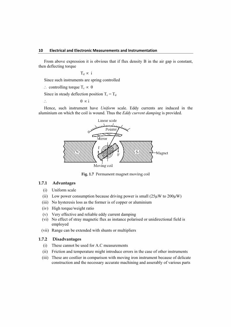
1.7.1 Advantages
(i) Uniform scale
(ii) Low power consumption because driving power is small (25µW to 200µW)
(iii) No hysteresis loss as the former is of copper or aluminium
(iv) High torque/weight ratio
(v) Very effective and reliable eddy current damping (vi) No effect of stray magnetic flux as instance polarised or unidirectional field is
employed
(vii) Range can be extended with shunts or multipliers
1.7.2 Disadvantages (i) These cannot be used for A.C measurements
(ii) Friction and temperature might introduce errors in the case of other instruments
(iii) These are costlier in comparison with moving iron instrument because of delicate construction and the necessary accurate machining and asserably of various parts
Measuring Instruments 11
(iv) The using of control spring and of permanent magnets might cause errors which can be considerably obviated by careful choice of material and preparing during manufacture.
1.7.3 Torque Equation
The Torque for a moving coil instrument is obtained for the basic law of the electromagnetic torque. The deflecting torque is given by,
Td = NB l dT or Td = NBAI
Td = GI
where G = NBA = constant
where,
Td = deflecting torque in N – m
B = flux density in air gap. Wb/m2
A = effective coil area. m2
N = number of tuns of the coil
I = current in the moving coil, amperes
The spring control provides a controlling torque and is proportional to the angular deflection of the pointer.
Tc = K
where, Tc = Controlling torque
K = Spring constant, Nm/rad (or) Nm/deg
= angular deflection
For final steady deflection
Tc = Td
Final steady state position
Tc = Td or GI = K
G
IK
Current K
IG
12 Electrical and Electronic Measurements and Instrumentation As the deflection is directly proportional to the current passing in the meter, we get a uniform scale for the instrument.
1.8 D’ Arsonval Galvanometer
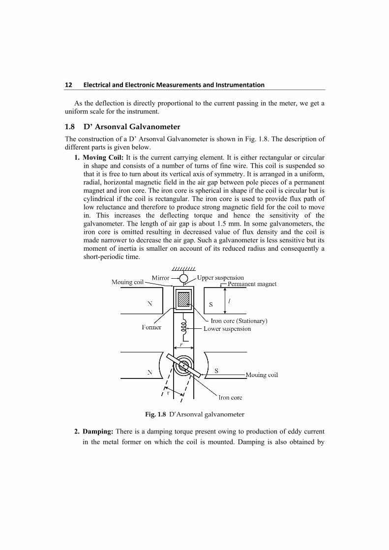
The construction of a D’ Arsonval Galvanometer is shown in Fig. 1.8. The description of different parts is given below.
1. Moving Coil: It is the current carrying element. It is either rectangular or circular in shape and consists of a number of turns of fine wire. This coil is suspended so that it is free to turn about its vertical axis of symmetry. It is arranged in a uniform, radial, horizontal magnetic field in the air gap between pole pieces of a permanent magnet and iron core. The iron core is spherical in shape if the coil is circular but is cylindrical if the coil is rectangular. The iron core is used to provide flux path of low reluctance and therefore to produce strong magnetic field for the coil to move in. This increases the deflecting torque and hence the sensitivity of the galvanometer. The length of air gap is about 1.5 mm. In some galvanometers, the iron core is omitted resulting in decreased value of flux density and the coil is made narrower to decrease the air gap. Such a galvanometer is less sensitive but its moment of inertia is smaller on account of its reduced radius and consequently a short-periodic time.
Fig. 1.8 D’Arsonval galvanometer
2. Damping: There is a damping torque present owing to production of eddy current
in the metal former on which the coil is mounted. Damping is also obtained by
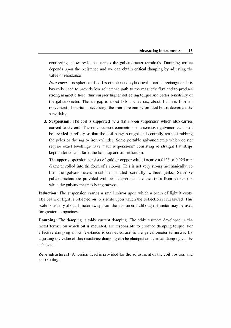
Measuring Instruments 13
connecting a low resistance across the galvanometer terminals. Damping torque
depends upon the resistance and we can obtain critical damping by adjusting the
value of resistance.
Iron core: It is spherical if coil is circular and cylindrical if coil is rectangular. It is
basically used to provide low reluctance path to the magnetic flux and to produce
strong magnetic field, thus ensures higher deflecting torque and better sensitivity of
the galvanometer. The air gap is about 1/16 inches i.e., about 1.5 mm. If small
movement of inertia is necessary, the iron core can be omitted but it decreases the
sensitivity.
3. Suspension: The coil is supported by a flat ribbon suspension which also carries
current to the coil. The other current connection in a sensitive galvanometer must
be levelled carefully so that the coil hangs straight and centrally without rubbing
the poles or the sag to iron cylinder. Some portable galvanometers which do not
require exact levellinge have “taut suspensions” consisting of straight flat strips
kept under tension far at the both top and at the bottom.
The upper suspension consists of gold or copper wire of nearly 0.0125 or 0.025 mm
diameter rolled into the form of a ribbon. This is not very strong mechanically, so
that the galvanometers must be handled carefully without jerks. Sensitive
galvanometers are provided with coil clamps to take the strain from suspension
while the galvanometer is being moved.
Induction: The suspension carries a small mirror upon which a beam of light it costs.
The beam of light is reflected on to a scale upon which the deflection is measured. This
scale is usually about 1 meter away from the instrument, although ½ meter may be used
for greater compactness.
Damping: The damping is eddy current damping. The eddy currents developed in the
metal former on which oil is mounted, are responsible to produce damping torque. For
effective damping a low resistance is connected across the galvanometer terminals. By
adjusting the value of this resistance damping can be changed and critical damping can be
achieved.
Zero adjustment: A torsion head is provided for the adjustment of the coil position and zero setting.
14 Electrical and Electronic Measurements and Instrumentation Indication: The suspension carries a small mirror upon which a beam of light is cast through a glass window in the outer brass case surrounding the instrument. The beam of light is reflected on the scale. The scale is usually 1 m away from the mirror.
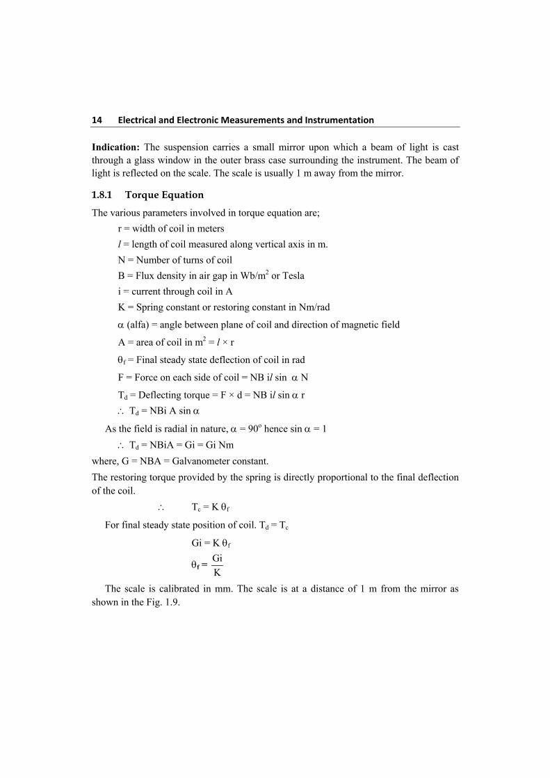
1.8.1 Torque Equation
The various parameters involved in torque equation are;
r = width of coil in meters
l = length of coil measured along vertical axis in m.
N = Number of turns of coil
B = Flux density in air gap in Wb/m2 or Tesla
i = current through coil in A
K = Spring constant or restoring constant in Nm/rad
(alfa) = angle between plane of coil and direction of magnetic field
A = area of coil in m2 = l × r
f = Final steady state deflection of coil in rad
F = Force on each side of coil = NB il sin N
Td = Deflecting torque = F × d = NB il sin r
Td = NBi A sin
As the field is radial in nature, = 90o hence sin = 1
Td = NBiA = Gi = Gi Nm
where, G = NBA = Galvanometer constant.
The restoring torque provided by the spring is directly proportional to the final deflection of the coil.
Tc = K f
For final steady state position of coil. Td = Tc
Gi = K f
f = Gi
K
The scale is calibrated in mm. The scale is at a distance of 1 m from the mirror as shown in the Fig. 1.9.
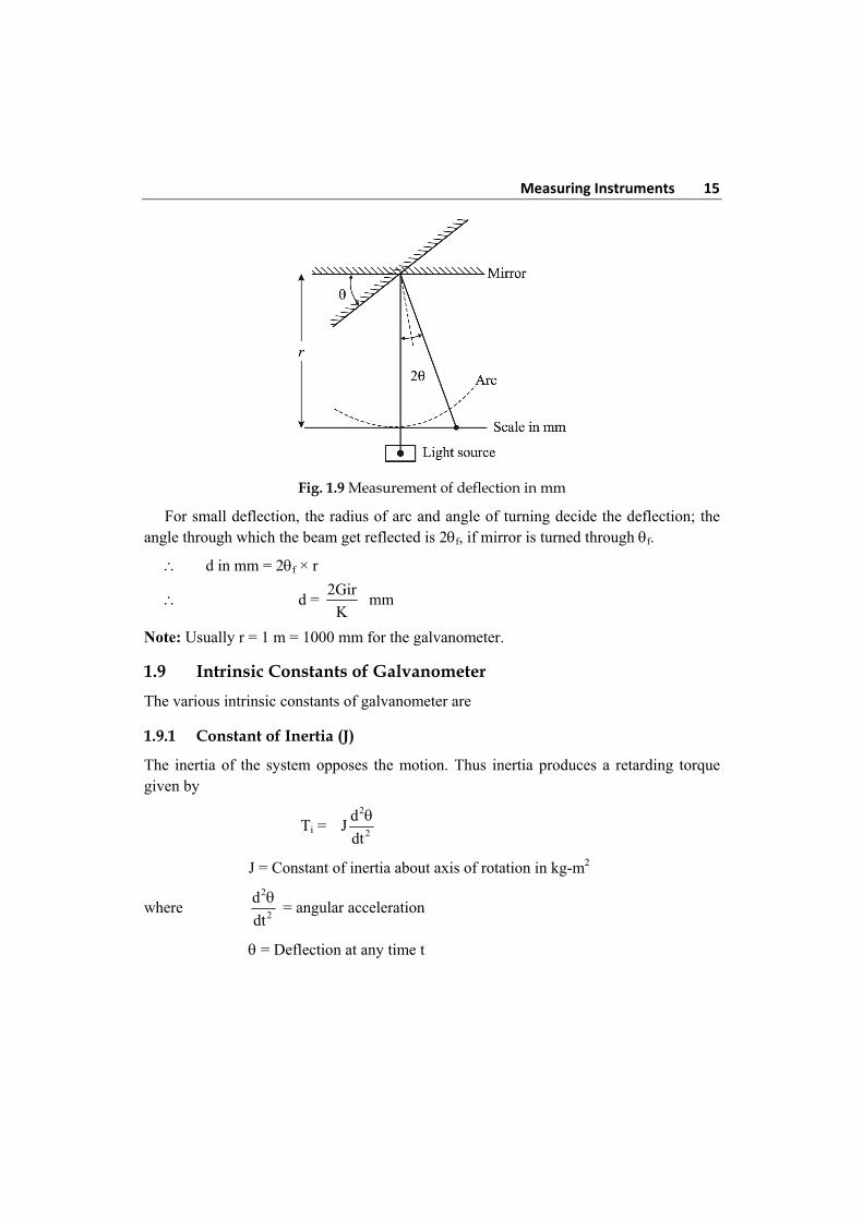
Measuring Instruments 15
Fig. 1.9 Measurement of deflection in mm
For small deflection, the radius of arc and angle of turning decide the deflection; the angle through which the beam get reflected is 2f, if mirror is turned through f.
d in mm = 2f × r
d = 2Gir
K mm
Note: Usually r = 1 m = 1000 mm for the galvanometer.
1.9 Intrinsic Constants of Galvanometer
The various intrinsic constants of galvanometer are
1.9.1 Constant of Inertia (J)
The inertia of the system opposes the motion. Thus inertia produces a retarding torque given by
Ti = 2
2
dJ
dt
J = Constant of inertia about axis of rotation in kg-m2
where 2
2
d
dt
= angular acceleration
= Deflection at any time t
16 Electrical and Electronic Measurements and Instrumentation 1.9.2 Control Constant
The elasticity of the suspension is proportional to the displacement which produces
controlling torque. This is required to bring the moving system back to the original
position
Tc = K
K = Control constant or restoring constant in Nm/rad
1.9.3 Displacement Constant (G)
The constant G defined in torque equation of a galvanometer is called displacement
constant.
G = NBA = NBl × r Nm/A
1.9.4 Damping Constant
Another torque retarding the motion is friction in air and elastic hysteresis in the
suspension. It is assumed to be proportional to the angular velocity of the moving system.
Td = D d
dt
D = Damping constant in Nm/rad s–1
1.10 Dynamic behaviour of Galvanometer
The dynamic behaviour of galvanometer is analysed through its equation of motion.
Thus 2
2
d dJ D K Gi
dtdt
This is second order differential equation governing the galvanometer motion. The
solution of this equation has two parts.
1. Complementary function (C.F)
2. Particular integral (P.I)
The C.F represents the transient behaviour while P.I represents the steady state
condition i.e., final deflection of the moving system.
Measuring Instruments 17
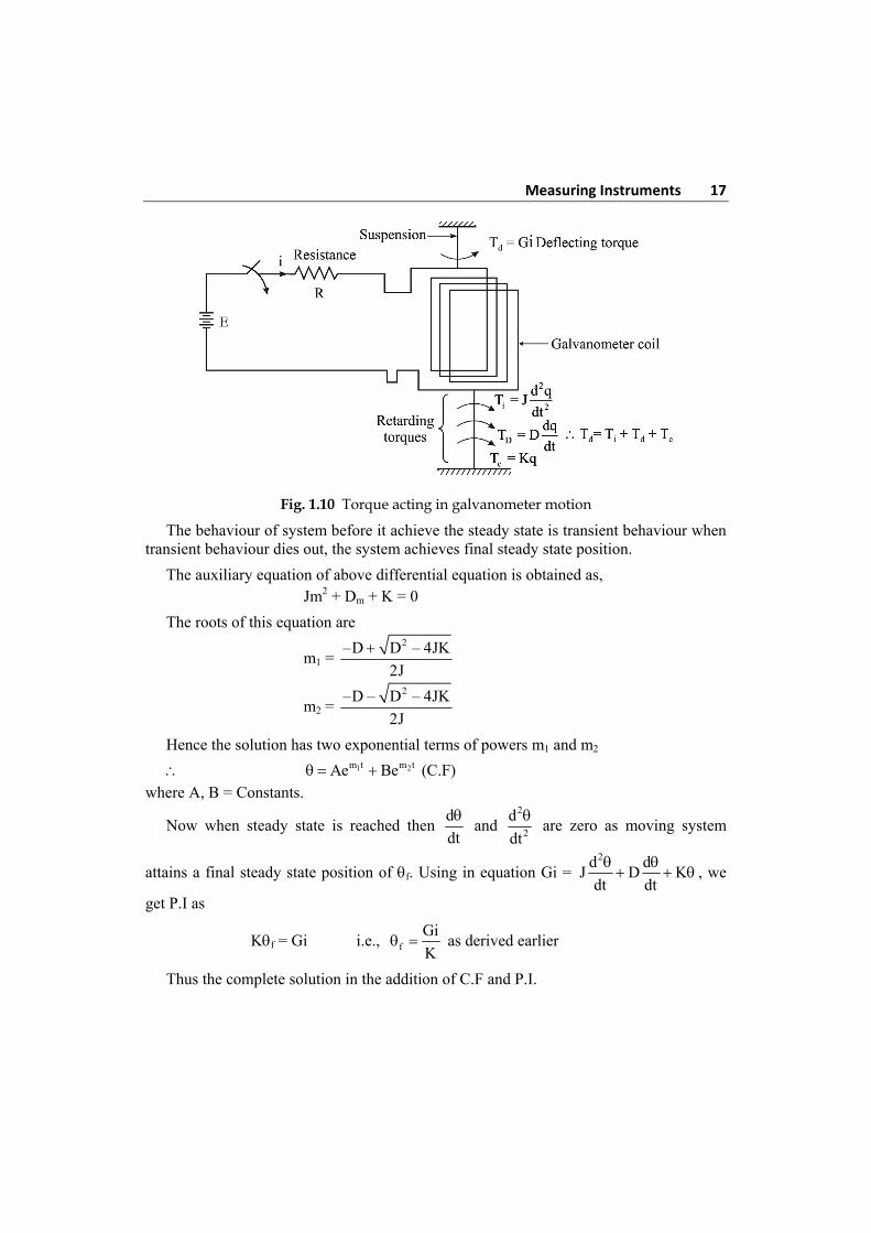
Fig. 1.10 Torque acting in galvanometer motion
The behaviour of system before it achieve the steady state is transient behaviour when transient behaviour dies out, the system achieves final steady state position.
The auxiliary equation of above differential equation is obtained as, Jm2 + Dm + K = 0
The roots of this equation are
m1 = 2–D D – 4JK
2J
m2 = 2–D – D – 4JK
2J
Hence the solution has two exponential terms of powers m1 and m2
1 2m t m tAe Be (C.F) where A, B = Constants.
Now when steady state is reached then d
dt
and
2
2
d
dt
are zero as moving system
attains a final steady state position of f. Using in equation Gi = 2d d
J D Kdt dt
, we
get P.I as
Kf = Gi i.e., f
Gi
K as derived earlier
Thus the complete solution in the addition of C.F and P.I.
18 Electrical and Electronic Measurements and Instrumentation
1 2m t m t
fA e B e
Transient term Steady state
Now the transient terms may be purely exponential or oscillatory which depends on the nature of roots m1 and m2. This defines the various damping conditions of the system.
1.11 Undamped Motion
The motion existing when damping is made zero i.e., D = 0 is called undamped motion of the system. The roots m1 and m2 are purely imaginary with zero real part for this case.
Note: The oscillations with zero damping are natural oscillations without opposition, having highest frequency. This frequency of undamped oscillations is called natural frequency of oscillations and denoted as n.
n = K
J rad/s [putting D = 0 in d]
= tan–124JK – D
D
= tan–1 = 90o, [D = 0]
Thus the solution of undamped motion is
0 of n
2 JK1 – e sin t 90
2 JK
= f [1 – cos nt]
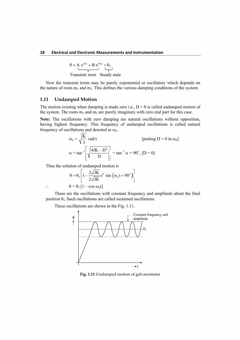
These are the oscillations with constant frequency and amplitude about the final position f. Such oscillations are called sustained oscillations.
These oscillations are shown in the Fig. 1.11.
Fig. 1.11 Undamped motion of galvanometer
Measuring Instruments 19
1.12 Underdamped Motion
Both m1 and m2 are complex conjugates of each other having negative real part.
D2 – 4KJ < 0 Underdamped
Note: The transient behaviour is damped oscillations i.e., oscillations of decreasing
amplitude. After sometime amplitude becomes zero and system achieves steady state.
The roots are imaginary and complex conjugates of each other represented as
m1, m2 = 2 2–D –1 4JK – D
2J
but –1 = J
m1, m2 = 2D– j 4JK – D – J d
2J …..(1.1)
where D
2J and
2
d
4JK – D
2J
Thus the solution becomes
d d– j t – – j tfA e B e …..(1.2)
d dj t – j t– tfe A e B e
But j – je cos jsin , e cos – sin
– td d d d fe A cos t + j sin t B cos t – j sin t
– td de A B cos t + j A – B sin t
– td de P cos Qsin t …..(1.3)
where P = A + B and Q = j(A – B)
Let – tdF e sin t …..(1.4)
– td dF e sin t cos +cos t sin …..(1.5)
Comparing equation (1.3) and equation (1.5), P = sin and Q = cos
Hence –1 P = tan
Q and 2 2F P Q
20 Electrical and Electronic Measurements and Instrumentation Thus the final equation for underdamped case is
D
– t2J
d fF e sin t …..(1.6)
where 2
d
4JK – D
2J = damped frequency of oscillations in rad/s
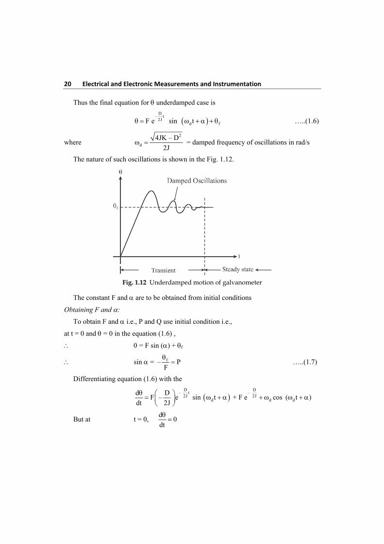
The nature of such oscillations is shown in the Fig. 1.12.
Fig. 1.12 Underdamped motion of galvanometer
The constant F and are to be obtained from initial conditions
Obtaining F and :
To obtain F and i.e., P and Q use initial condition i.e.,
at t = 0 and = 0 in the equation (1.6) ,
= F sin () + f
sin = f– PF
…..(1.7)
Differentiating equation (1.6) with the
D D
– t – 2J 2J
d d d
d DF – e sin t + F e cos ( t )
dt 2J
But at t = 0, d
0dt
Measuring Instruments 21
F
d
D0 – sin F cos
2J
…..(1.8)
tan = d
2J
P =
24JK – D 2J
D D
tan = 24JK – D
D …..(1.9)
Using (1.7) and (1.8)
fd
D0 – F – F cos
2J F
f
d
Dcos – Q
2JF
…..(1.10)
But sin2 + cos2 = 1
22
f f
d
D– – 1
F 2J F
2 2 2
df 2 2
d
4J DF –
4J
…..(1.11)
Using d = 24JK – D
2J in equation (1.11)
F = – f 2
2 JK
4JK – D
…..(1.12)
Using equation (1.9) and (1.11) in equation (1.6)
D
– t 2J
f d f2
2 JK– e sin t
4JK – D
D
– t 2J
f d2
2 JK1 – e sin t
4JK – D
…..(1.13)
The angular frequency is d hence
2
dd
1 4JK – Df Hz
2 2 2J
…..(1.14)
Td = time period
22 Electrical and Electronic Measurements and Instrumentation
d 2d
1 2JT 2
f 4JK – D
…..(1.15)
1.13 Critically Damped Motion
For critically damping, the roots m1 and m2 are equal, real and negative. Thus
D2 – 4JK = 0 i.e., D2 = 4JK and
D = 2 JK for critical damping
m1 = m2 = D
–2J
and D = 2 JK
Note: For this case, the transient response is not critically damped oscillatory but purely exponential such that pointer attains the steady position of very quickly.
As the response is not oscillatory, equation (1.13) is not applicable for this case, the solution for the critically damped case is,
D
– t2J
f e A Bt ……(1.16)
Using t = 0, = 0
0 = f + A …..(1.17)
Differentiating (1.16) and using t = 0, d
0dt
,
D D
– t – t2J 2Jd D
– e A Bt e Bdt 2J
0 = D
– A B2J
…..(1.18)
A = – f and B = – fD
2J
D
– t2J
f
D1 – e 1 t
2J
…..(1.19)
The value of damping constant for the critical damping is denoted by Dc and
Dc = 2 JK .
Thus, n
D 2 JK K
2J 2J J
Using in equation (1.19)
n– tf n1– e 1 t …..(1.20)
Measuring Instruments 23
1.14 Overdamped Motion
The amount of damping is mathematically measured by defining a ratio of actual damping D and critical damping Dc. This is called a damping ratio and denoted by a greek letter . This is also called relative damping.
= c
D DDamping ratio
D 2 JK …..(1.21)
Thus when the actual damping is more than the damping for critical case, the motion is called overdamped and the roots m1 and m2 are real, unequal and negative.
Note: For overdamped case, the transient motion is purely exponential and nonoscillatory. The pointer attains final position of exponentially, taking more time than that of critical damping.
More the value of damping, the pointer response is slow and sluggish, taking more time to attain the final position.
Note: For critical damping = 1 while for overdamped case the damping ratio > 1.
The solution for overdamped motion interms of is given as,
2nn
2 2– t( –1)– t 2
f 2 2
–1 – 1e – –1 – e
1 2 –1 2 –1
…..(1.22)
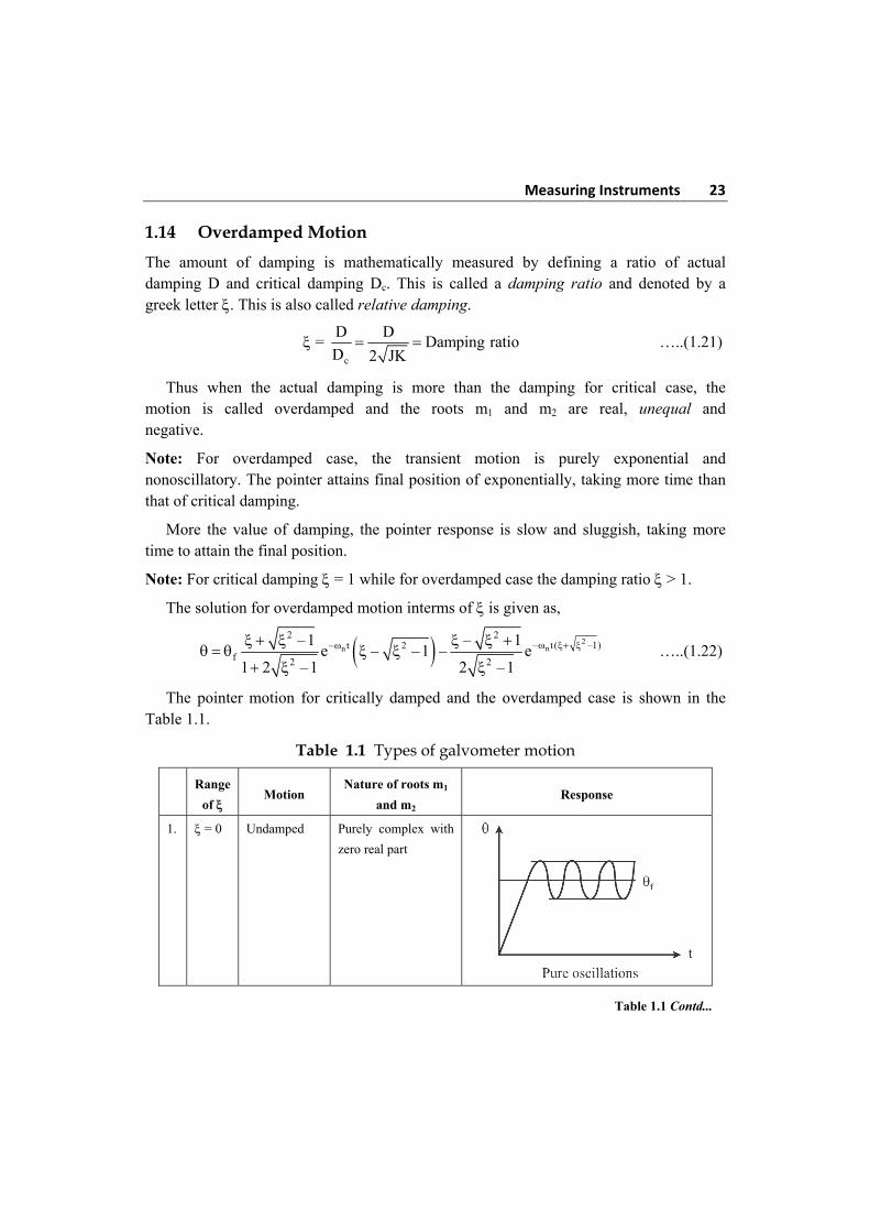
The pointer motion for critically damped and the overdamped case is shown in the Table 1.1.
Table 1.1 Types of galvometer motion
Range
of Motion
Nature of roots m1
and m2 Response
1. = 0 Undamped Purely complex with
zero real part
Table 1.1 Contd...
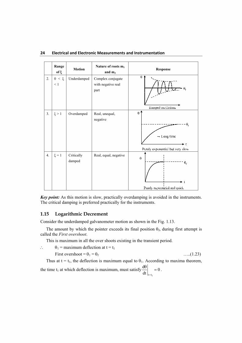
24 Electrical and Electronic Measurements and Instrumentation
Range
of Motion
Nature of roots m1
and m2 Response
2. 0 <
< 1
Underdamped Complex conjugate
with negative real
part
3. > 1 Overdamped Real, unequal,
negative
4. = 1 Critically
damped
Real, equal, negative
Key point: As this motion is slow, practically overdamping is avoided in the instruments. The critical damping is preferred practically for the instruments.
1.15 Logarithmic Decrement
Consider the underdamped galvanometer motion as shown in the Fig. 1.13.
The amount by which the pointer exceeds its final position f, during first attempt is called the First overshoot. This is maximum in all the over shoots existing in the transient period.
1 = maximum deflection at t = t1
First overshoot = 1 = f …..(1.23)
Thus at t = t1, the deflection is maximum equal to 1. According to maxima theorem,
the time t1 at which deflection is maximum, must satisfy1t t
d0
dt
.
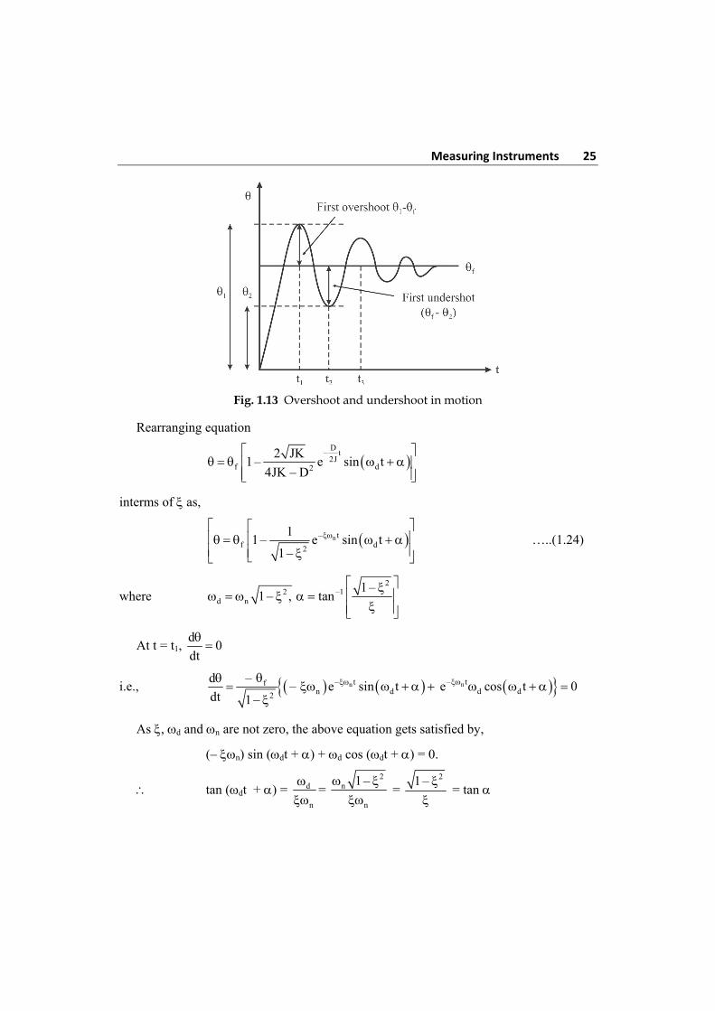
Measuring Instruments 25
Fig. 1.13 Overshoot and undershoot in motion
Rearranging equation
D
– t2J
f d2
2 JK1 – e sin t
4JK – D
interms of as,
n– tf d2
11 – e sin t
1 –
…..(1.24)
where 2
2 –1d n
1 –1 – , tan
At t = t1, d
0dt
i.e., n– tfn d2
– d– e sin t
dt 1 –
n– t
d de cos t 0
As , d and n are not zero, the above equation gets satisfied by,
(– n) sin (dt + ) + d cos (dt + ) = 0.
tan (dt + ) = d
n
= 2
n
n
1 –
= 21 –
= tan
26 Electrical and Electronic Measurements and Instrumentation This equation is satisfied when dt = n because tan (n + ) = tan .
t = d
n
For first overshoot n = 1, t = t1
t1 = 2
d n 1 –
…..(1.25)
Putting in equation 1.24
1 = f[1 + 2– 1–e ] …..(1.26)
Note that sin 1
d
πd 1 t =ω
( t + α) = + sin = 21 –
First overshoot = 1 – f = f (2– 1–e ) …..(1.27)
At n = 2 + t2 = d
2
–2 21–
2 f 1 – e
first undershoot = –2 21–f 2 f– e
…..(1.28)
Taking ratio of first over and undershoots
2
2
2
– 1–1–1 f
–2 1–f 2
– ee
– e
…..(1.29)
ln 1 f
2f 2
–
– 1 –
…..(1.30)
The natural logarithm of the ratio of two successive swings is called logarithmic decrement and denoted by .
1 f
f 2
–n
– 1 –
l …..(1.31)
Now, d 2d n
2 2T
1 –
Measuring Instruments 27
While on
2T
2o
d
T1 –
T …..(1.32)
= d
o
T
T
……(1.33)
where To = time period corresponding to n.
Thus equation = f D
– t2J
d2
2 JK1 – e sin t
4JK – D
can be expressed as,
o–2 t /T –1d of
o d d
T T2 t1 – e sin sin
T T T
…..(1.34)
d– t / –1nf d
d
1 – e sin t sin …..(1.35)
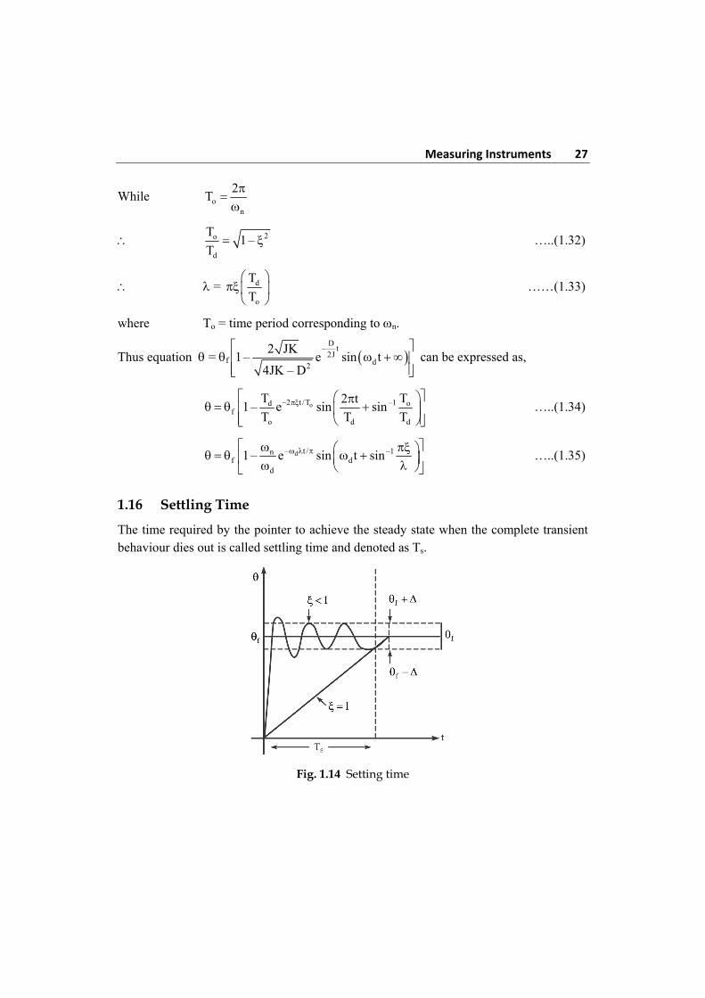
1.16 Settling Time
The time required by the pointer to achieve the steady state when the complete transient behaviour dies out is called settling time and denoted as Ts.
Fig. 1.14 Setting time
28 Electrical and Electronic Measurements and Instrumentation Practically as the exponential term is present in the equation, and is kept between 0.6 to 1 and motion is underdamped hence oscillatory. While a particular band is defined about f denoted by + . When transient oscillations decrease and enter into f + zone and remain thereafter. Within this interval then it is said that the pointer has achieved the steady state. This is shown in the Fig. 1.14.
For 2% band defined from accuracy point of view,
Ts = n
4
This is possible for between 0.6 to 1.0 hence practically is designed between this range.
1.17 Effect of External Resistance on Damping
The damping opposition to the motion by dissipating the energy of radiation. In galvanometer the damping is provided by two types.
1.17.1 Mechanical Damping
This is due to the friction present in the mechanical of the pointer. This is not very significant. The damping torque produced due to such mechanical objects is given by,
Tm = m
dD
dt
where Dm = Mechanical damping constant
1.17.2 Electromagnetic Damping
This is effective damping than the mechanical damping. It is produced due to reduced effect when coil moves in a magnetic field. Thus when coil moves in a magnetic fields,
(i) The eddy currents are induced in the metal former.
(ii) The emf is induced in coil which circulates through coil
These two effects cause damping called electromagnetic damping.
Let R = Resistance of galvanometer circuit= Rg + Rx
where Rg = resistance of galvanometer coil
Rx = External resistance connected for damping
When coil rotates, emf is induced in it which is given by,
e = 2N × Blv
Measuring Instruments 29
where r r d
V = linear velocity2 2 2t
e r d d2NB NBA r = Area A
2 dt dt
l l
but G = NBA
e = G d
dt
i = e G d
R R dt
The torque produced due to this current flowing through the coils is
Tcoil = N × Bil × r = NBA i = Gi
Tcoil = G × 2
coil
G d G d d D
R dt R dt dt
where Dcoil = Damping constant of coil circuit
2
coil
GD
R
Now let us find damping due to the metal former.
It consists of one strip i.e., N = 1.
Tf = Bil × r = BAi
Now BA = G
N and i =
f
G d
N R dt
as N = 1 for former
where Rf = Resistance of former.
Ti = 2
former2f f
G G d G d dD
N N R dt dt dtN R
where Dformer = Damping constant of former
2
former 2f
GD
N R
Total electromagnetic damping = (Dcoil + Dformer) d
dt
30 Electrical and Electronic Measurements and Instrumentation
2 2
e 2f
G G dT
R dtN R
e
dT De
dt
2 2
e 2f
G GD
R N R = (G2/N2Rf) damping constant due to electromagnetic damping
Total damping due to both effect is,
TD = Tm + Te = [Dm + De] d d
Ddt dt
where D = Dm + De
1.18 Critical Resistance for Damping
The mechanical damping is very small and can be neglected.
D = De = 2 2
2f
G G
R N R
Practically, the damping due to metal former is also very small.
D = 2G
R
For the critical damping, = 1 R = Rc and D = Dc = 2 JK
2
c
G2 JK
R
Rc = 2G 2 JK
2
x c g g
GR R – R – R
2 JK
This is the value of external resistance required to adjust damping to the critcal damping. It is called external critical damping resistance (ECDR).
1.19 Sensitivity of Galvanometer
The sensitivity of galvanometer can be defined with respect to current, voltage or resistance of galvanometer. Thus there are three sensitivities associated with a galvanometer.
Measuring Instruments 31
1.19.1 Voltage Sensitivity
It is defined as the deflection obtained in scale divising per unit voltage impressed on the galvanometer.
Sv = g
V m / V
i R .....(1.36)
1.19.2 Current Sensitivity
It is defined as the deflection obtained per unit current.
Si = f iG Grad/H
i Ki K
…..(1.37)
Practically the value of current and deflection are very small, hence the current sensitivity is expressed in mm/A.
Si = d
i but d = 2f ; r = i2G
rK
Si = 2Gr
K m/A
As usually r = 1 m = 1000 mm,
Si = 6
2000G G mm/μA
500KK 10
But d = 2Gir 2000Gi
K K in mm for r = 1 m
Sv = 6
g
2000Gi mm/μV
iKR 10
Sv = g
G
500 K R mm/V …..(1.38)
1.19.3 Megohm Sensitivity
It is the resistance of the circuit in megohm so that the deflection is one scale division when one volt is impressed in the galvanometer.
S0 = –6
d M / scale division
i 10
…..(1.39)
32 Electrical and Electronic Measurements and Instrumentation
But d = 2000 Gi
mm for r = 1 mK
,
S0 = G
M / mm500 K
…..(1.40)
For high sensitivity, G must be larger and K should be small. As G = NBA, to get high sensitivity, coil must be having more N, more cross-section area and must be placed in high flux density magnetic field. Hence the coil has large number of turns of fine were as area of cross-section cannot be increased beyond limits. The K can be decreased by using small stiffness constants springs.
1.20 Errors in Moving Coil Instruments
The common errors are accountable due to change in temperature, friction, mechanical unbalance, and operational. These are discussed in detail below.
1.20.1 Temperature Error
Apart from the change in room temperature, a change in temperature in the coil and in the spring effects the instrument reading as a whole. Increase in temperature of the coil increases its resistance, due to which the current decrease proportionately resulting in decrease in deflection. When the instrument is used as voltmeter, resistance also increases in the associated high resistance connected in series. With the effect that the deflection of the coil decreases, besides, increase in temperature of the control spring decreases stress in it. With the result that reading shows an error. To some extent, the error is minimised by winding the series resistance coil of material of very small temperature co-efficient of resistance. Hence the instrument has a temperature range of working.
1.20.2 Mechanical Unbalance
The efficiency of the moving system is high only when the weight of the moving system is well balanced and acts on that Jewel disturbed, bearing axially. Under any circumstance of use if the balance is destroyed, the friction between the pivot and the jewel bearing dominates, resulting decrease in deflection. Besides an unbalanced coil will have sluggish movement due to which the torque produced is also affected. The effect of these is the decrease in deflection. To overcome this the following precautions are taken during use.
1. The instrument should not be given any jerk during use.
2. As far as possible the instruments should be used in a position which keeps the spindle vertical.
3. The instrument should not be operated near a heater or other heating appliances.
Measuring Instruments 33
1.20.3 Frictional Error
The mechanical frictional force acting at the pivots oppose the deflecting force. At the time of initial graduation of the sale this is taken into account but as time elapses, the frictional surface gets effected and friction increases due to which errors in the deflection results. These errors are minimised by adopting a moving system of light construction, mounted on jewelled bearing and keeping the moving system dust proof.
1.20.4 Observational Error
This error is due to misreading of the scale/parallax in reading and error estimation. Errors due to parallax is eliminated by providing a mirror below the pointer under the slit provided in the scale.
1.20.5 Ageing
Constant use of meters and ageing affects the stress in the control spring due to which the controlling torque decreases and the deflection increases. This amounts to failure of control mechanism which is rectified by replacing the control spring with new one and the instrument recalibrated.
A meter is said to have 100% accuracy when the reading of the pointer and the actual reading are equal. The error in the meter is said to be zero. If the error exists, the level of accuracy falls to that extent. Normally for a good design, the error percentage lies between + 0.05% to + 5% for full scale deflection.
An instrument which takes least current for the full scale deflection is said to be more sensitive. The ampere turns of the moving coil being constant for a set design, the least current for full scale deflection can be obtained by having higher number of turns. Another point to be kept in mind is the torque weight ratio. The least weight of the moving system will have higher torque therefore, increasing the number of turns means increase in weight. Hence, there should be a compromise between the number of turns in the moving coil and torque weight ratio, for an economical result. Sensitivity is normally measured in ohm/volt of full scale deflection. Higher is the value, higher is the sensitivity of the instrument. A 20000 ohms/volt instrument is more sensitive than a 1000 /volt meter.
1.21 Moving Iron Instrument
The most commonly used ammeter and voltmeters in laboratories and switch board at commercial frequencies are moving iron instrument. These instruments are cheap, robust, and can be manufactured to reasonable accuracy. The operating principle is simple. It
34 Electrical and Electronic Measurements and Instrumentation consists of a vane of soft iron of high permeability steel which forms the moving system of the instrument along with the pointer, spring, pivots and damping device. The vane is so situated that it gets attracted or repelled from by a magnetic force in a solenoid carrying current. While doing so, it deflects proportional to the quantity being measured. Thus there are two general types of moving iron instruments.
1. Attraction type
2. Repulsion type
The attraction type instruments operate on the principle of operation of single piece of soft iron into a magnetic field and repulsion type instruments operate on the principle of repulsion of two adjacent iron pieces magnetised by the same magnetic field. In both types of these instruments, the current to be measured or a definite fraction of the current to be measured proportional to the voltage to be measured it passed through a coil of wire. This current carrying coil sets up the necessary field. A certain number of ampere-turns is required for the operation of the instrument and this number can be made up either having a few turns and large current vice-versa. The instrument to be used as an ammeter is provided with a coil of few turns of thick wire in order to have low resistance and carry large current, and that to be used as a voltmeter is provided with a coil of large number of turns of fine wire in order to have high resistance and draw as small current as possible.
1.21.1 Attraction (or single-iron) Type M.I Instrument
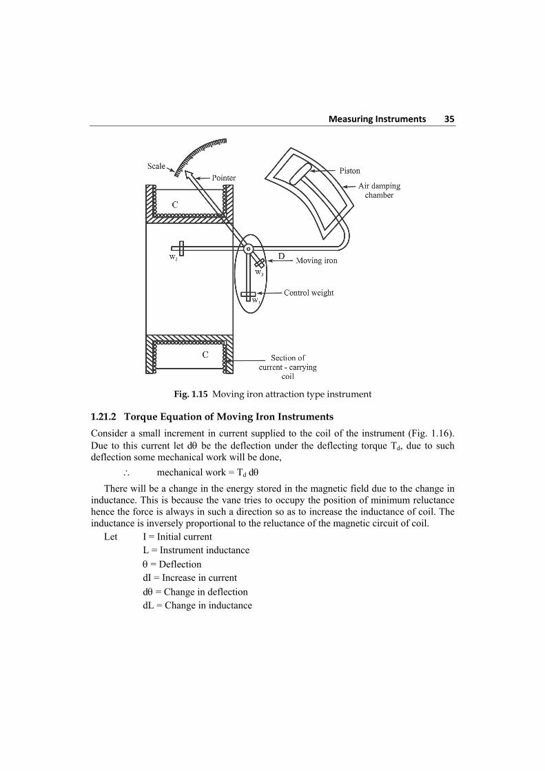
Section of view of attraction type moving iron instrument is shown in Fig. 1.16. It consists essentially of a coil or solenoid and oval shaped iron pivoted in such a way that it can move in or out of the solenoid. To this iron a pointer is attached so that it may deflect along with the moving iron over a graduated scale. The iron is made of sheet metal specially shaped to give a scale as nearly uniform as possible. When the current to be measured (or a definite fraction of the current to be measured or propogational to the voltage to be measured) is passed through the solenoid, a magnetic field is set up inside the solenoid which in turn magnetises the iron. Thus the iron is attracted into the coil, causing the spindle and the pointer to rotate. The design of the shape of the iron is largely by trial. Such instruments normally have spring control an pneumatic damping. In Fig. 1.15 gravity control attraction type instrument is shown. This has been superceded by spring control instruments. These are better than the gravity control instruments as these can be used in any position. Hence M.I instrument can be used for both AC & DC measurements. Due to square law response, the scale of the moving iron instrument is non-uniform.
Measuring Instruments 35
Fig. 1.15 Moving iron attraction type instrument
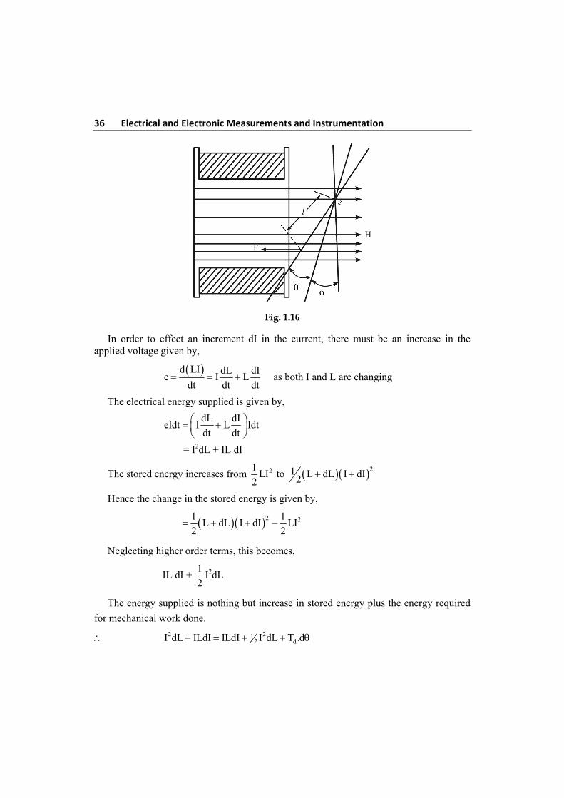
1.21.2 Torque Equation of Moving Iron Instruments
Consider a small increment in current supplied to the coil of the instrument (Fig. 1.16). Due to this current let d be the deflection under the deflecting torque Td, due to such deflection some mechanical work will be done,
mechanical work = Td d
There will be a change in the energy stored in the magnetic field due to the change in inductance. This is because the vane tries to occupy the position of minimum reluctance hence the force is always in such a direction so as to increase the inductance of coil. The inductance is inversely proportional to the reluctance of the magnetic circuit of coil. Let I = Initial current L = Instrument inductance
= Deflection dI = Increase in current
d = Change in deflection dL = Change in inductance
36 Electrical and Electronic Measurements and Instrumentation
Fig. 1.16
In order to effect an increment dI in the current, there must be an increase in the applied voltage given by,
d LI dL dI
e I Ldt dt dt
as both I and L are changing
The electrical energy supplied is given by,
dL dI
eIdt I L Idtdt dt
= I2dL + IL dI
The stored energy increases from 21LI
2 to 21 L dL I dI2
Hence the change in the stored energy is given by,
2 21 1L dL I dI – LI
2 2
Neglecting higher order terms, this becomes,
IL dI + 1
2I2dL
The energy supplied is nothing but increase in stored energy plus the energy required
for mechanical work done.
2 212 dI dL ILdI ILdI I dL T .d
Measuring Instruments 37
Td.d = 1
2 I2dL
Td = 1
2 I2 dL
d
While the controlling torque is given by,
Tc = K
where K = Spring constant
21 dLK I
2 d
under equilibrium
21 I dL
2 K d
Thus the deflection is proportional to the square of the current through the coil and the
instrument gives square law response.
Ranges:
1. Ammeter from about 0.02 A to 0.800 A maximum without current transformer.
2. Voltmeters from about 0.1 V to 0.800 V maximum without potential transformer.
1.22 Moving Iron Repulsion Type Instrument (Double-Iron) Type
These instruments have two vanes inside the coil, the one is fixed and other is movable. When the current flows in the coil, both the vanes are magnetised with like polarities induced on the same side. Hence due to the repulsion of like polarities, there is a force of repulsion between the two vanes causing the movement of the moving vane. The repulsion type instruments are the most commonly used instruments.
The two different designs of repulsion type instruments are:
1. Radial vane type and 2. Co-axial vane type
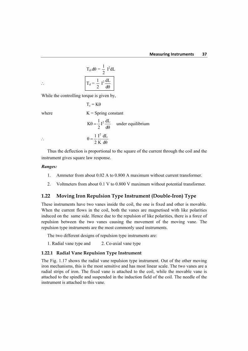
1.22.1 Radial Vane Repulsion Type Instrument
The Fig. 1.17 shows the radial vane repulsion type instrument. Out of the other moving iron mechanisms, this is the most sensitive and has most linear scale. The two vanes are a radial strips of iron. The fixed vane is attached to the coil, while the movable vane is attached to the spindle and suspended in the induction field of the coil. The needle of the instrument is attached to this vane.
38 Electrical and Electronic Measurements and Instrumentation
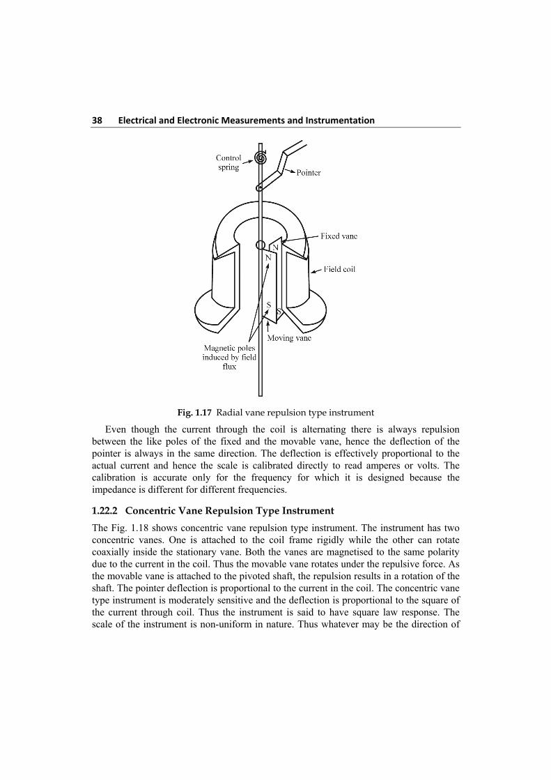
Fig. 1.17 Radial vane repulsion type instrument
Even though the current through the coil is alternating there is always repulsion between the like poles of the fixed and the movable vane, hence the deflection of the pointer is always in the same direction. The deflection is effectively proportional to the actual current and hence the scale is calibrated directly to read amperes or volts. The calibration is accurate only for the frequency for which it is designed because the impedance is different for different frequencies.
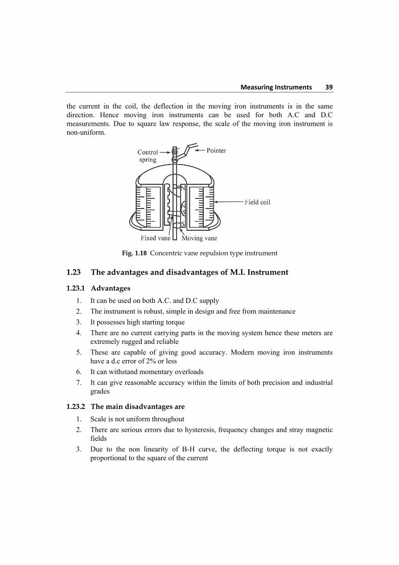
1.22.2 Concentric Vane Repulsion Type Instrument
The Fig. 1.18 shows concentric vane repulsion type instrument. The instrument has two concentric vanes. One is attached to the coil frame rigidly while the other can rotate coaxially inside the stationary vane. Both the vanes are magnetised to the same polarity due to the current in the coil. Thus the movable vane rotates under the repulsive force. As the movable vane is attached to the pivoted shaft, the repulsion results in a rotation of the shaft. The pointer deflection is proportional to the current in the coil. The concentric vane type instrument is moderately sensitive and the deflection is proportional to the square of the current through coil. Thus the instrument is said to have square law response. The scale of the instrument is non-uniform in nature. Thus whatever may be the direction of
Measuring Instruments 39
the current in the coil, the deflection in the moving iron instruments is in the same direction. Hence moving iron instruments can be used for both A.C and D.C measurements. Due to square law response, the scale of the moving iron instrument is non-uniform.
Fig. 1.18 Concentric vane repulsion type instrument
1.23 The advantages and disadvantages of M.I. Instrument
1.23.1 Advantages
1. It can be used on both A.C. and D.C supply
2. The instrument is robust, simple in design and free from maintenance
3. It possesses high starting torque
4. There are no current carrying parts in the moving system hence these meters are extremely rugged and reliable
5. These are capable of giving good accuracy. Modern moving iron instruments have a d.c error of 2% or less
6. It can withstand momentary overloads
7. It can give reasonable accuracy within the limits of both precision and industrial grades
1.23.2 The main disadvantages are
1. Scale is not uniform throughout
2. There are serious errors due to hysteresis, frequency changes and stray magnetic fields
3. Due to the non linearity of B-H curve, the deflecting torque is not exactly proportional to the square of the current
40 Electrical and Electronic Measurements and Instrumentation 4. The stiffness of the spring decreases with increase in temperature
5. Change in frequency of operation causes serious error.
6. Power consumption at low voltage is high
1.24 Errors in M.I Instrument
There are two types of errors which occur in moving iron instrument. Errors which occur with both A.C and D.C and the other which occur only with A.C only.
Errors with both D.C and A.C
1.24.1 Hysteresis Error
This error occurs as the value of flux density is different for the same current for ascending and descending values. The value of flux density is higher for descending value of current (and voltage) than for ascending values. This error can be minimized by making the iron parts small so that they demagnetize themselves quickly. Another matched is to work the iron parts at low values of flux density so that the hysteresis effects are small.
Hysteresis may produce a 2 to 3% error. With the use of nickel iron alloys with narrow hysteresis loops, the error may be brought down to less than 0.05%.
1.24.2 Stray Magnetic Fields
The error due to stray magnetic fields (fields other than the operating magnetic field) may be appreciable. As the operating magnetic field is weak (about 0.006 to 0.0075 ub/m2 at full scale deflection) and hence can be easily distorted. Such errors depend upon the direction of the stray magnetic field relative to the field of the instrument. These errors can be minimized by using an iron case or a thin iron shield over the working parts.
1.24.3 Temperature Error
The effect of temperature changes on moving iron instrument arises chiefly from the temperature coefficient of spring. The error may be 0.02% per oC change in temperature. In voltmeters, error are caused due to self-heating of coil and series resistance. The temperature of the coil may increase by 10 to 20oC for a power consumption of 1 W. The resistance increases (by about 4 to 8%), causing a decrease in current for a given voltage. This produces a decreased deflection. Therefore the series resistance should be made a material like manganin which has a small temperature co-efficient. The value of series resistance should be very large as compared with the coil resistance in order to minimize errors due to self-heating. In the case of switch board instruments, the series resistance is about 10 times the coil resistance.
Measuring Instruments 41
1.25 Errors with A.C only
1.25.1 Frequency Error
Changes in frequency may cause errors due to changes of reactance of the working coil and also due changes of magnitude of eddy current set up in the metal parts of instrument.
1.25.2 Reactance of Instrument Coil
The change of reactance of the instrument coil is important in case of voltmeters where an additional resistance Rs is used in series with the instrument coil. Let the resistance and inductance of the instrument coil be R and L. Then the current I in the instrument coil for a given applied voltage ‘V’ is given by:
I = 2 2 2
S
V
(R R ) L
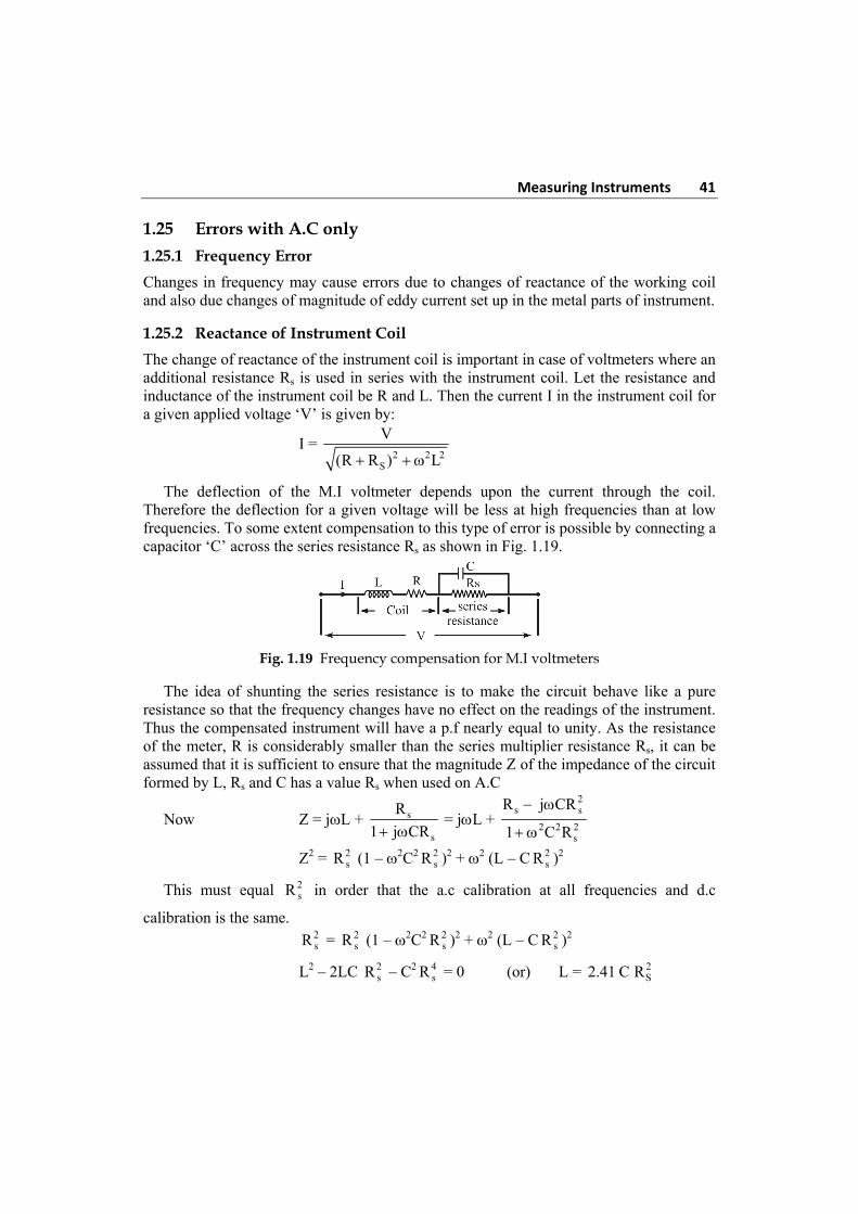
The deflection of the M.I voltmeter depends upon the current through the coil. Therefore the deflection for a given voltage will be less at high frequencies than at low frequencies. To some extent compensation to this type of error is possible by connecting a capacitor ‘C’ across the series resistance Rs as shown in Fig. 1.19.
Fig. 1.19 Frequency compensation for M.I voltmeters
The idea of shunting the series resistance is to make the circuit behave like a pure resistance so that the frequency changes have no effect on the readings of the instrument. Thus the compensated instrument will have a p.f nearly equal to unity. As the resistance of the meter, R is considerably smaller than the series multiplier resistance Rs, it can be assumed that it is sufficient to ensure that the magnitude Z of the impedance of the circuit formed by L, Rs and C has a value Rs when used on A.C
Now Z = jL +
2s ss
2 2 2s s
R j CRR = j L +
1 j CR 1 C R
Z2 = 2sR (1 – 2C2 2
sR )2 + 2 (L – C 2sR )2
This must equal 2sR in order that the a.c calibration at all frequencies and d.c
calibration is the same.
2sR = 2
sR (1 – 2C2 2sR )2 + 2 (L – C 2
sR )2
L2 – 2LC 2sR – C2 4
sR = 0 (or) L = 2S2.41 C R
42 Electrical and Electronic Measurements and Instrumentation
C = 2 2s s
1 L L = 0.41
2.41 R R
C = 0.41 2s
L
R
It should be understood that the above analysis is valid for limited range of frequency which in practical cases is up to 125 Hz.
1.25.3 Eddy Current Error
When instrument is used for a.c measurement, the eddy currents are produced in the iron parts of the instrument. The eddy current affects the instrument current causing the change in the deflecting torque. This produces the error in the meter reading. As eddy currents are frequency dependent, frequency change cause eddy current error.
1.25.4 Hysteresis Error
Due to hysteresis effect, the flux density for the same current while ascending and descending values is different. While descending, the flux density is higher and while ascending it is lesser. So meter reads higher for descending value of current or voltage. So remedy for this is to use smaller iron parts which can demagnetise quickly or to work with lower flux densities.
1.26 Comparison between moving Coil and moving Iron Instrument
Moving Coil Moving Iron 1. Coil moves in the magnetic field 1. Soft iron moves in the magnetic field 2. Deflecting torque is proportional to
current 2. Deflecting torque is proportional to square of
the current
3. Damping is provided by eddy current 3. Damping is provided by air friction
4. Spring controlled instrument 4. Gravity controlled instrument
5. Controlling torque is proportion to the angle of deflection
5. Controlling torque is proportion to sin
6. Scale is uniform 6. Non-uniform scale, cramped at the beginning and at end
7. Delicate, sensitive and accurate 7. Robust, reasonable accurate
8. Costly 8. Cheap
9. Low power consumption 9. Power consumption is higher than moving coil
10. It is used in D.C circuit 10. It can be used in both A.C and D.C circuit
11. Can be used as voltmeter, Ammeter, Galvanometer and ohmmeter
11. Can be used as ammeter, voltmeter and wattmeter.
Measuring Instruments 43
1.27 Basic D.C Ammeter
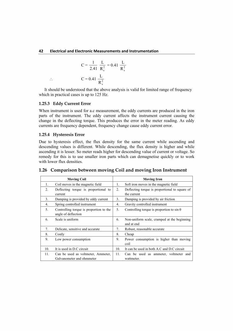
The basic d.c ammeter is nothing but a DArsonval galvanometer. The coil winding of a basic meter is very small and light and hence it can carry very small currents. So as mentioned earlier, for large currents, the major part of current is required to be by passed using a resistance called “shunt”. It is shown in the Fig. 1.20.
Fig. 1.20 Basic d.c ammeter
The shunt resistance can be calculated as:
Let Rm = internal resistance of coil
Rsh = shunt resistance
Im = full scale deflection current
Ish = shunt current
I = total current
I = Ish + Im
As the two resistances Rsh and Rm are in parallel, the voltage drop across them is same.
Ish Rsh = Im Rm Rsh = m m
sh
I R
I
but Ish = I – Im
Rsh = m m
m
I R
I I Rsh = mR
(m 1)
where, m = m
I
I
The m is called “multiplying power” of the shunt and defined as the ratio of total current to the current through the coil. It can be expressed as,
m = m
I
I = 1 + m
sh
R
R
The shunt resistance may consist of a constant temperature resistance wire within the case of the meter or it may be external shunt low resistance.
44 Electrical and Electronic Measurements and Instrumentation Thus to increase the range of ammeter ‘m’ times, the shunt resistance required is
1
(m 1) times the basic meter resistance. This is nothing but “extension of ranges of an
ammeter”.
1.28 Multi Range Ammeters
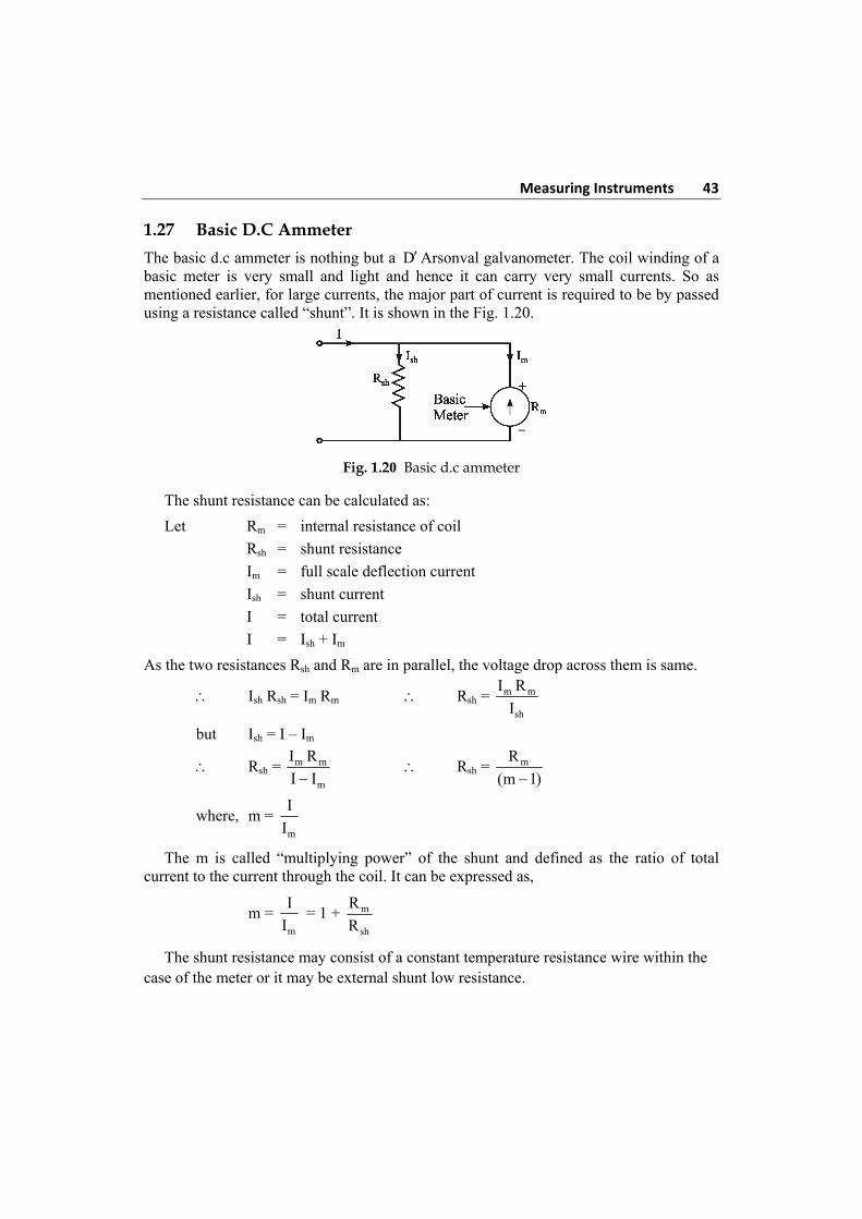
The range of the basic d.c ammeter can be extended by using number of shunts and a selector switch. Such a meter is called “Multi range ammeter” and shown in the Fig. 1.21.
R1, R2, R3 and R4 are four shunts. When connected in parallel with the meter, they can give four different ranges I1, I2, I3 and I4. The selector switch S is multi position switch, having low contact resistance and high current carrying capacity. The make before break type switch is used for the range changing. If the ordinary switch is used while range changing, the switch remains open and full current passes through the meter. The meter may get damaged due to such high current. So make before break switch is used. The design of such switch is so that it makes contact with next terminal before completely breaking the contact with previous terminal. The multi range ammeters are used for the ranges up to 50 A. While using the multi range ammeter, highest range should be used first and thus the current range should be decreased till good upscale reading is obtained. All the shunts are very precise resistance and hence cost of such multi range ammeter is high.
Fig. 1.21 Multi-range ammeter
The mathematical analysis of basic d.c ammeters equally applicable to such multi range ammeter. Thus,
R1 = mR
m 1
R2 = m
2
R
m 1 at so on
where m1, m2, m3 …. are the multiplying powers for the currents I1, I2, I3 ….
Measuring Instruments 45
1.29 The Aryton Shunt or Universal Shunt
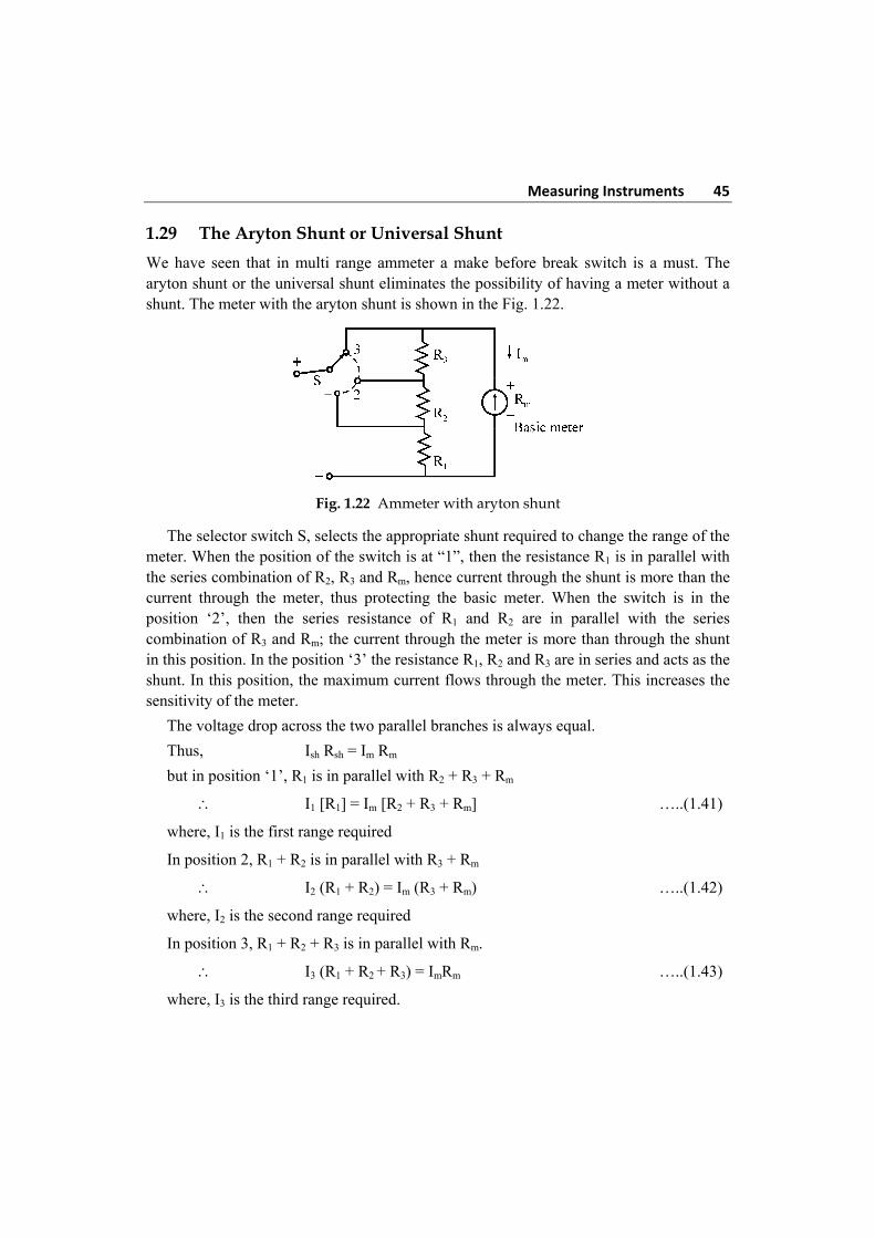
We have seen that in multi range ammeter a make before break switch is a must. The aryton shunt or the universal shunt eliminates the possibility of having a meter without a shunt. The meter with the aryton shunt is shown in the Fig. 1.22.
Fig. 1.22 Ammeter with aryton shunt
The selector switch S, selects the appropriate shunt required to change the range of the meter. When the position of the switch is at “1”, then the resistance R1 is in parallel with the series combination of R2, R3 and Rm, hence current through the shunt is more than the current through the meter, thus protecting the basic meter. When the switch is in the position ‘2’, then the series resistance of R1 and R2 are in parallel with the series combination of R3 and Rm; the current through the meter is more than through the shunt in this position. In the position ‘3’ the resistance R1, R2 and R3 are in series and acts as the shunt. In this position, the maximum current flows through the meter. This increases the sensitivity of the meter.
The voltage drop across the two parallel branches is always equal.
Thus, Ish Rsh = Im Rm
but in position ‘1’, R1 is in parallel with R2 + R3 + Rm
I1 [R1] = Im [R2 + R3 + Rm] …..(1.41)
where, I1 is the first range required
In position 2, R1 + R2 is in parallel with R3 + Rm
I2 (R1 + R2) = Im (R3 + Rm) …..(1.42)
where, I2 is the second range required
In position 3, R1 + R2 + R3 is in parallel with Rm.
I3 (R1 + R2 + R3) = ImRm …..(1.43)
where, I3 is the third range required.
–
46 Electrical and Electronic Measurements and Instrumentation The current range I3 is the minimum while I1 is the maximum range possible. Solving the equations (1.41), (1.42) and (1.43) the required Aryton shunt can be designed.
1.30 Requirement of a Shunt
1. The shunt resistance should be stable and cast out with time.
2. The shunt resistance should not carry currents which will cause excessive temperature rise.
3. The temperature co-efficient of shunt and the meter should be low and should be as equal as possible.
4. The type of material used to join the shunts should have low thermo dielectric voltage drop i.e., the soldering of joints should not cause a voltage drop.
5. The resistance should have low thermal electromotive force with copper.
6. Due to the soldering, the values of resistance should not be changed.
The “MANGANIN” is usually used for the shunts of d.c instruments while the constant is useful for the shunt of a.c instruments.
1.31 Precautions to be taken while using an Ammeter
1. While using multi range ammeter, first use the highest current range and then decrease the current range until sufficient deflection is obtained. So to increase the accuracy, finally select the range which will give the reading near full scale deflection.
2. The polarities must be observed correctly. The opposite polarities deflect the pointer in opposite direction against the mechanical stop and this may damage the pointer.
3. As the ammeter resistance is very low, it should never be connected across any source of e.m.f. Always connect an ammeter in series with the load.
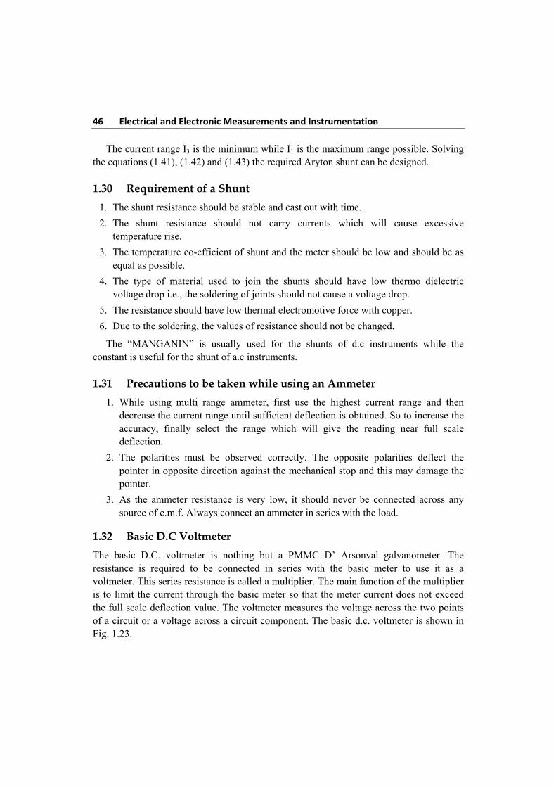
1.32 Basic D.C Voltmeter
The basic D.C. voltmeter is nothing but a PMMC D’ Arsonval galvanometer. The resistance is required to be connected in series with the basic meter to use it as a voltmeter. This series resistance is called a multiplier. The main function of the multiplier is to limit the current through the basic meter so that the meter current does not exceed the full scale deflection value. The voltmeter measures the voltage across the two points of a circuit or a voltage across a circuit component. The basic d.c. voltmeter is shown in Fig. 1.23.
Measuring Instruments 47
Fig. 1.23 Basic D.C voltmeter
The voltmeter must be connected across the two points or a component to measure the potential difference, with the proper polarity.
The multiplier resistance can be calculated as,
Let Rm = Internal resistance of meter
Rs = series multiplier resistance
Im = full scale deflection current
V = full range voltage to be measured
From Fig. 1.23
V = Im (Rm + Rs)
V = ImRm + ImRs
ImRs = V – ImRm
Rs = mm
VR
I
The “multiplying factor” for multiplier is the ratio of full range voltage to be measured and the drop across the basic meter.
Let v = drop across the basic meter = ImRm
m = multiplying factor = m m s
m m
I (R R )V
v I R
m = 1 + s
m
R
R
Hence multiplier resistance can also be expressed as,
Rs = (m – 1) Rm
–
+
48 Electrical and Electronic Measurements and Instrumentation Thus to increase the range of voltmeter ‘m’ times, the series resistance required is (m – 1) times the basic meter resistance. This is nothing but “extension of ranges of a voltmeter”.
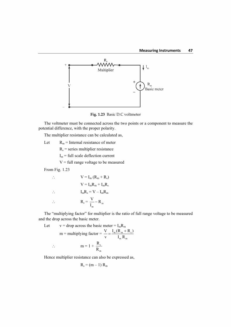
1.32.1 Multirange Voltmeter
The range of the basic d.c voltmeter can be extended by using number of multipliers and a selector switch. Such a meter is called “multi range voltmeter” and is shown in the Fig. 1.24.
The R1, R2, R3 and R4 are the four series multipliers.
When connected in series with meter, they can give four different voltage range as V1, V2, V3 and V4. The selector system ‘S’ is multi position switch by which the required multiplier can be selected in the circuit.
Fig. 1.24 Multirange voltmeter
The mathematical analysis of basic d.c voltmeter is equally applicable for such multi-range thus,
1 21 m 2 m
m m
V VR – R , R – R
I I and so on
1.32.2 Practical Multirange Voltmeter
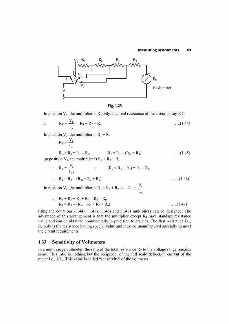
In this arrangement (Fig. 1.25) the multipliers are connected in a series string, the connections are brought out from the junctions of the resistance. The selector switch is used to select the required voltage range.
When the switch S is at position V1, R1 + R2 + R3 + R4 acts as a multiplier resistance. When the switch S is at position V4 is the lowest voltage range while ‘V1’ is the maximum voltage range.
More practical arrangement of multiplier resistance is shown in the Fig. 1.25. The multiplier resistance can be calculated as:
–
Measuring Instruments 49
Fig. 1.25
In position V4, the multiplier is R4 only, the total resistance of the circuit is say RT.
RT = 4
m
V
I R4 = RT – Rm …..(1.44)
In position V3, the multiplier is R3 + R4
RT = 3
m
V
I
R3 + R4 = RT – Rm R3 = RT – (Rm + R4) …..(1.45)
on position V2, the multiplier is R2 + R3 + R4
RT = 2
m
V
I , (R2 + R3 + R4) = RT – Rm
R2 = RT – (Rm + R3 + R4) …..(1.46)
In position V1, the multiplier is R1 + R3 + R4 RT = 1
m
V
I
R1 + R2 + R3 + R4 = RT – Rm R1 = RT – (Rm + R2 + R3 + R4) …..(1.47)
using the equations (1.44), (1.45), (1.46) and (1.47) multipliers can be designed. The advantage of this arrangement is that the multiplier except R4 have standard resistance value and can be obtained commercially in precision tolerances. The first resistance i.e., R4 only is the resistance having special value and must be manufactured specially to meet the circuit requirements.
1.33 Sensitivity of Voltmeters
In a multi range voltmeter, the ratio of the total resistance RT to the voltage range remains same. This ratio is nothing but the reciprocal of the full scale deflection current of the meter i.e., 1/Im. This value is called “sensitivity” of the voltmeter.
50 Electrical and Electronic Measurements and Instrumentation Thus the sensitivity of the voltmeter is defined as
S = 1
full scale deflection current
S = m
1 K
I V V
(ohm/V or kilo ohm/V)
Note: The sensitivity range is specified on the meter dial and it indicates the resistance of the meter for a one volt range.
The internal resistance of the voltmeter is not the same in each of its ranges. The higher is the range of the voltmeter, greater is its internal resistance. Internal resistance of a voltmeter can be obtained from its sensitivity as,
Internal resistance of voltmeter = maximum voltage (range) × sensitivity in / V
The sensitivity is useful in calculating the resistance of a multiplier in d.c. voltmeter.
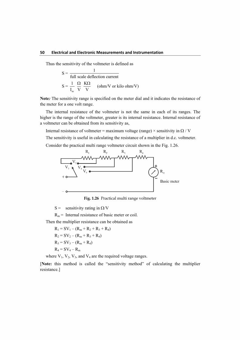
Consider the practical multi range voltmeter circuit shown in the Fig. 1.26.
Fig. 1.26 Practical multi range voltmeter
S = sensitivity rating in /V
Rm = Internal resistance of basic meter or coil.
Then the multiplier resistance can be obtained as
R1 = SV1 – (Rm + R2 + R3 + R4)
R2 = SV2 – (Rm + R3 + R4)
R3 = SV3 – (Rm + R4)
R4 = SV4 – Rm
where V1, V2, V3, and V4 are the required voltage ranges.
[Note: this method is called the “sensitivity method” of calculating the multiplier resistance.]
Measuring Instruments 51
1.34 Loading Effect
While selecting a meter for a particular measurement, the sensitivity rating is very important. A low sensitive meter may give the accurate reading in low resistance circuit but will produce totally inaccurate reading in high resistance circuit.
The voltmeter is always connected across the two parts between which the potential difference is to be measured. It is connected across a low resistance then as voltmeter in high, most of the current will pass through a low resistance and will produce the voltage drop which will be nothing, but the true reading, but if the voltmeter is connected across the high resistance then due to two high resistance in parallel, the current will divide almost equally through two paths. Thus the meter will record the voltage drop across the high resistance which will be much lower than the true reading.
Thus the low sensitivity instrument when used in high resistance circuit gives a lower reading than the true reading. This is called “LOADING EFFECT” of the volt meter. It is mainly cause due to low sensitivity instruments.
1.35 Requirements of a Multiplier
1. The change in their resistance with temperature should be small.
2. They should be non-inductively wound for a.c. meters.
3. Their resistance should not change with time.
Commonly used resistance materials for construction of a multiplier are mangenin and constantan.
1.36 Precautions to be taken while using a Voltmeter
The following precautions must be taken while using a voltmeter:
1. While using the multi range voltmeter, first use the highest range and then decrease the voltage range until the sufficient deflection is obtained.
2. Take care of the loading effect. The effect can be minimised by using high sensitivity voltmeters.
3. The polarities must be observed correctly. The wrong polarities deflect the pointer in the opposite direction against the mechanical stop and this may damage the pointer.
4. The voltmeter resistance is very high and it should always be connected across the circuit or component whose voltage is to be measured.
1.37 Ammeter and Voltmeter
The meters which connected in series with the circuit whose current is to be measured are called “ammeter”. The power loss in ammeter is I2 Ra. Where Ra is ammeter resistance. To have low power loss, ammeter resistance must be very low.
52 Electrical and Electronic Measurements and Instrumentation The meters which are connected in parallel with the circuit whose voltage is to be measured are called “voltmeters”. The power loss in voltmeter is V2/Rv where Rv is voltmeter resistance. To have low power loss, voltmeter resistance must be very high.
The construction and working principle of both the meters is same. Both are basically current sensing devices but they have following difference.
Ammeter Voltmeter 1. It is a current measuring device which
measures current through circuit 1. Which measure potential difference between the
two points of a circuit.
2. Always connected in series with circuit. 2. Always connected in parallel with the circuit.
3. The resistance is very small. 3. The resistance is, very high.
4. Deflection torque is produced by current to be measured directly.
4. Deflecting torque is produced by a current which is proportional to the voltage to be measured.
Electrostatic Instruments
Basically electrostatic instruments are all are voltmeters. Practically such instruments may be used for measurement of current and power but both the types of measurements require measurement of voltage across a known independence. The main advantage of such instruments is the measurement of high voltage in both A.C and D.C circuits without any errors due to eddy current losses and hysteresis.
Force and Torque equation of Electrostatic Instruments
The electrostatic instruments is based on the operation principle that there exists a force between the two plates with opposite charges; this force can be obtained using the principle that the mechanical work done is equal to the stored energy if there is a relative motion of Plates, the principle of electrostatic voltmeter is as shown in the Fig. 1.27.
Consider two plates A and B where Plate A is fixed and plate B is movable. The plates are oppositely charged and are restrained by a spring connected to the fixed point. Let potential difference of ‘V’ volt be applied to the plates; then a force of attraction F-newton exists between them. Plate B moves towards A until this force is balanced by that of the spring. The capacitance between the plate is then C-farad and the stored energy E is
21E CV Joule
2 .....(1.48)
When applied voltage increases by dV, the current flowing through capacitance also changes and t is given by.
dQ di CV
dt dt Q CV .....(1.49)
Measuring Instruments 53
dV dC
I C Vdt dt
The input electrical energy is given by iE V I dt
= dV dC
V C V dtdt dt
= 2CV dV V dC .....(1.50)
and also to the change in applied voltage by value dV, the capacitance increase by dC because plate B moves towards a fixed plate A. Which decreases the distance of separation between two plates increasing net capacitance.
The new energy stored is given by
21E ' C+dC V dV
2
.....(1.51)
The change in stored energy is given by
2 21 1E ' E C+dC V dV CV
2 2
= 2 2 21 1C+dC V 2V dV + dV CV
2 2
= 2 2 2 2 21 1 1 1 1CV CVdV CdV V dC 2VdVdC dCdV CV
2 2 2 2 2
Neglecting higher order terms of small quantities such as dC and dV, we get
21E ' E V dC CVdV
2 ......(1.52)
from the law of conservation of energy we have,
Input energy = Increment in stored energy + mechanical work done Ei E ' E Fdx
2 21CVdV V dC V dC CVdV Fdx
2
2 21Fdx CVdV V dC V dC CVdV
2
21Fdx V dC
2
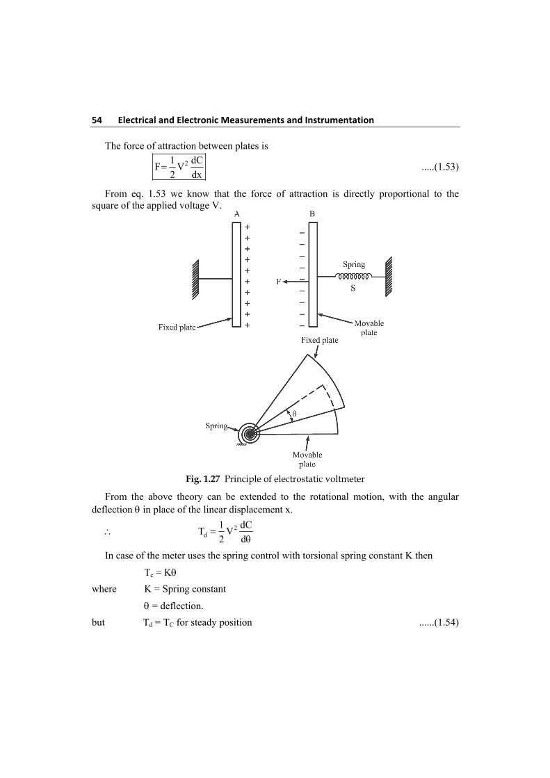
54 Electrical and Electronic Measurements and Instrumentation The force of attraction between plates is
21 dCF V
2 dx .....(1.53)
From eq. 1.53 we know that the force of attraction is directly proportional to the square of the applied voltage V.
Fig. 1.27 Principle of electrostatic voltmeter
From the above theory can be extended to the rotational motion, with the angular deflection in place of the linear displacement x.
2d
1 dCT V
2 d
In case of the meter uses the spring control with torsional spring constant K then
Tc = K
where K = Spring constant
= deflection.
but Td = TC for steady position ......(1.54)
Measuring Instruments 55
21 dCV K
2 d
21 dCV
2k d
.....(1.55)
Since
1. The deflection is proportional to the square of voltage to be measured. The scale is non uniform which is compressed at the lower end. (square low response)
2. This instrument can be used for A.C and D.C measurements as the deflection is proportional to the square of the voltage to be measured.
1.38 Type of Electrostatic Voltmeters
Operating Principle
The operating principle of an electrostatic instrument depends on the force of attraction between two or more electrically charged conductors between which a potential difference in maintained and this force gives rise to a deflection torque. The electrostatic mechanism resembles a variable capacitor. Where the force existing between the two parallel plates is a function of the potential difference applied to them.
Basically there are two types of Electrostatic instruments.
1. Quadrant type (10 kV to 20 kV)
2. Attracted – disc type (above 20 kV)
1.38.1 Quadrant – Type Electrostatic Voltmeter
Quadrant – Type electrometers are used for the measurement of voltage up to 10 kV to 20 kV.
Construction and working: It consists essentially of two sets of mutual plates, one movable and the other fixed, the former being of very light construction (e.g., of aluminium). The movable plate, together with the end of the spiral spring, is attached to the spindle carrying the pointer of the instrument (Fig. 1.28). These two plates (fixed & movable) constitute a capacitor whose capacitance changes as the pointer moves on the scale.
When the voltage to be measured is applied between the fixed and movable plates. The plates acquire opposite charges that are proportional to the potential difference or the voltage. The electric field set up between the plates causes the movable plate field and pointer to move to the right until the deflecting force is balanced by a spring or other restoring force. The deflecting torque is directly proportional to the square of the applied voltage and thus, these instruments measure r.m.s voltages.
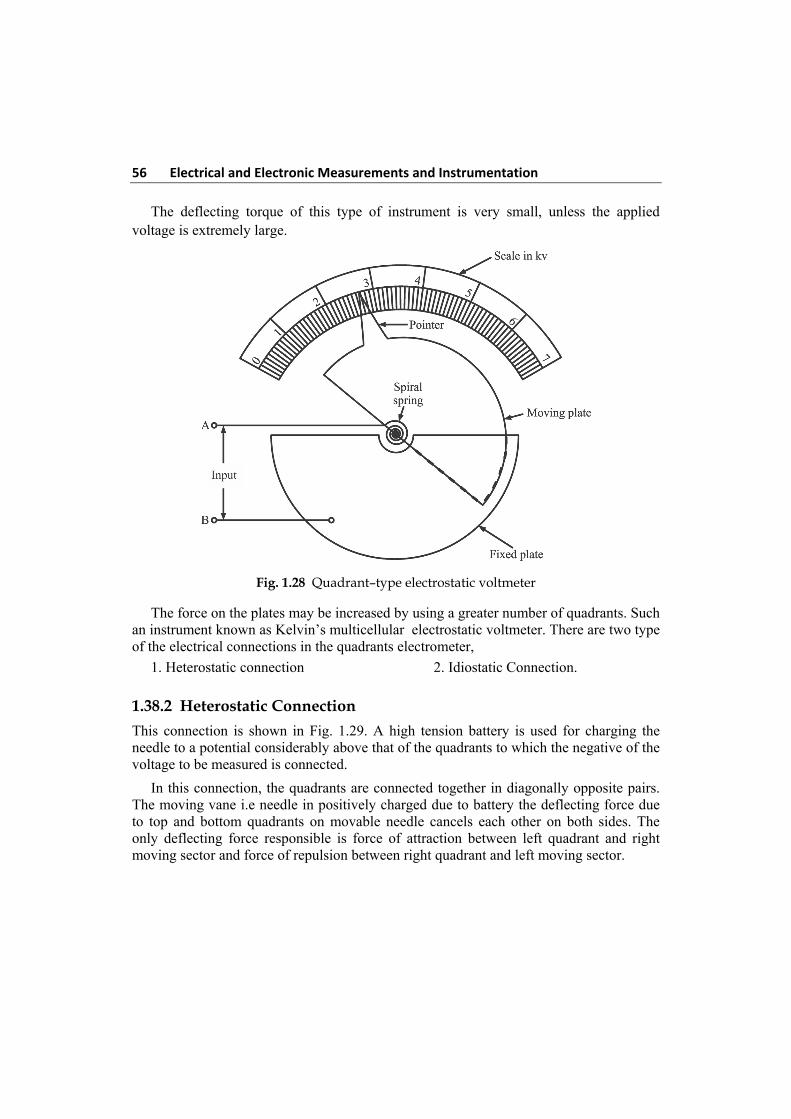
56 Electrical and Electronic Measurements and Instrumentation The deflecting torque of this type of instrument is very small, unless the applied voltage is extremely large.
Fig. 1.28 Quadrant–type electrostatic voltmeter
The force on the plates may be increased by using a greater number of quadrants. Such an instrument known as Kelvin’s multicellular electrostatic voltmeter. There are two type of the electrical connections in the quadrants electrometer,
1. Heterostatic connection 2. Idiostatic Connection.
1.38.2 Heterostatic Connection
This connection is shown in Fig. 1.29. A high tension battery is used for charging the needle to a potential considerably above that of the quadrants to which the negative of the voltage to be measured is connected.
In this connection, the quadrants are connected together in diagonally opposite pairs. The moving vane i.e needle in positively charged due to battery the deflecting force due to top and bottom quadrants on movable needle cancels each other on both sides. The only deflecting force responsible is force of attraction between left quadrant and right moving sector and force of repulsion between right quadrant and left moving sector.
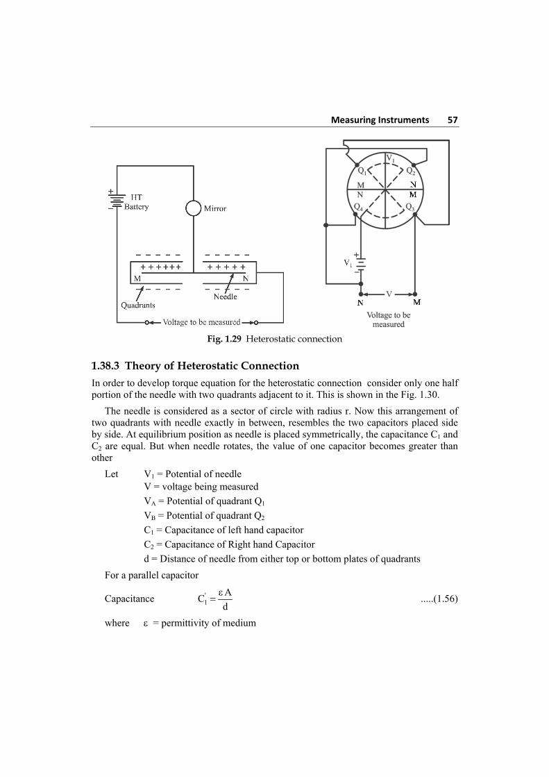
Measuring Instruments 57
Fig. 1.29 Heterostatic connection
1.38.3 Theory of Heterostatic Connection
In order to develop torque equation for the heterostatic connection consider only one half portion of the needle with two quadrants adjacent to it. This is shown in the Fig. 1.30.
The needle is considered as a sector of circle with radius r. Now this arrangement of two quadrants with needle exactly in between, resembles the two capacitors placed side by side. At equilibrium position as needle is placed symmetrically, the capacitance C1 and C2 are equal. But when needle rotates, the value of one capacitor becomes greater than other
Let V1 = Potential of needle V = voltage being measured
VA = Potential of quadrant Q1
VB = Potential of quadrant Q2
C1 = Capacitance of left hand capacitor
C2 = Capacitance of Right hand Capacitor
d = Distance of needle from either top or bottom plates of quadrants
For a parallel capacitor
Capacitance '1
AC
d
.....(1.56)
where = permittivity of medium
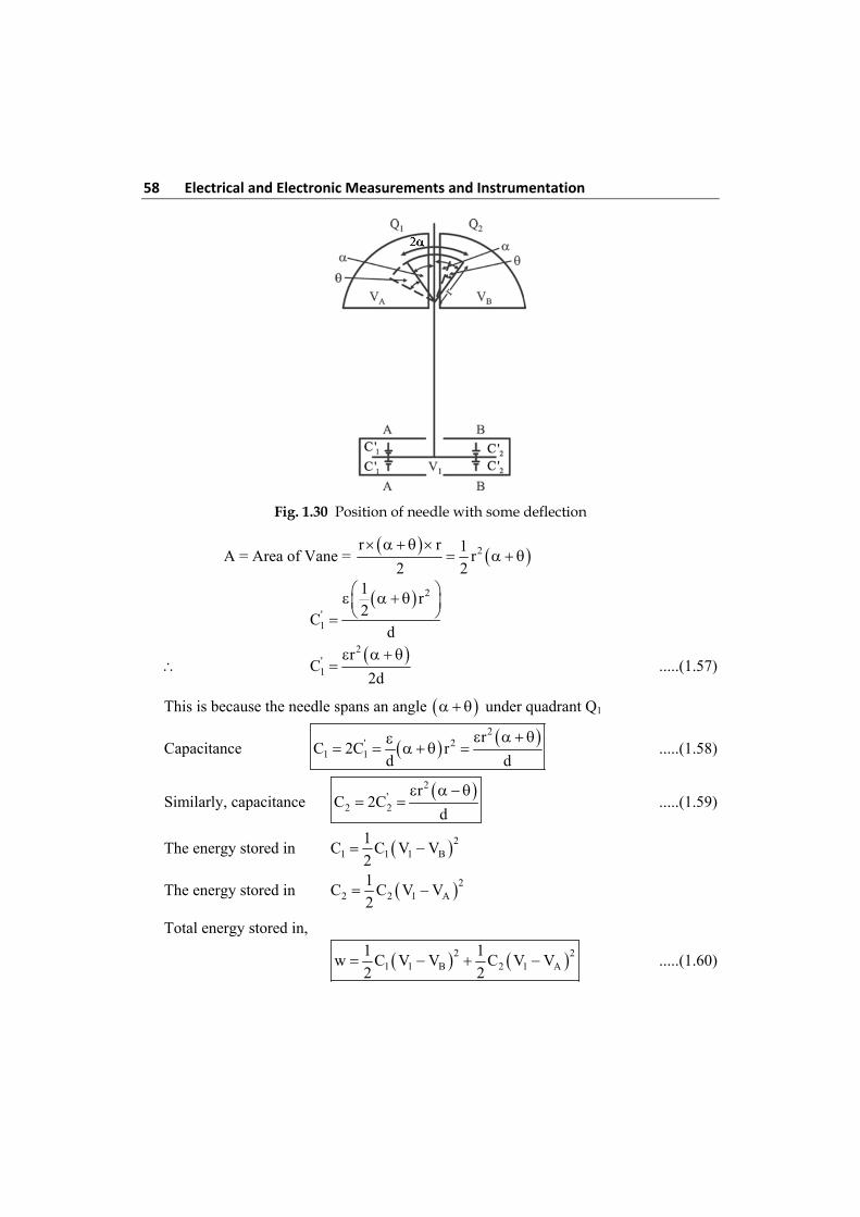
58 Electrical and Electronic Measurements and Instrumentation
Fig. 1.30 Position of needle with some deflection
A = Area of Vane = 2r r 1
r2 2
2
'1
1r
2C
d
2
'1
rC
2d
.....(1.57)
This is because the needle spans an angle under quadrant Q1
Capacitance 2' 2
1 1
rC 2C r
d d
.....(1.58)
Similarly, capacitance 2
'2 2
rC 2C
d
.....(1.59)
The energy stored in 21 1 1 B
1C C V V
2
The energy stored in 22 2 1 A
1C C V V
2
Total energy stored in,
2 21 1 B 2 1 A
1 1w C V V C V V
2 2 .....(1.60)
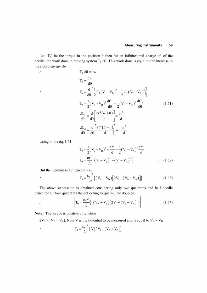
Measuring Instruments 59
Let ‘T’ be the torque in the position then for an infinitesimal charge d of the needle, the work done in moving system T d. This work done is equal to the increase in the stored energy dw.
T d dw
dw
Td
2 21 1 B 2 1 A
d 1 1T C V V C V V
d 2 2
2 21 21 B 1 A
dC dC1 1T V V V V
2 d 2 d
.....(1.61)
2 2
1 rdC d r
d d d d
2 2
2 rdC d r
d d d d
Using in the eq. 1.61
2 2
2 21 B 1 A
1 r 1 rT V V V V
2 d 2 d
2
2 21 B 1 A
rT V V V V
2d ......(1.62)
But the medium is air hence = 0
2
00 A B 1 B A
rT V V 2V V V
2d
.....(1.63)
The above expression is obtained considering only two quadrants and half needle hence for all four quadrants the deflecting torque will be doubled.
2
0A B 1 B A
rT V V 2V (V V
d
.....(1.64)
Note: The torque is positive only when
2V1 > (VB + VA). Now V is the Potential to be measured and is equal to VA – VB
2
01 B A
rT V 2V (V V
2d
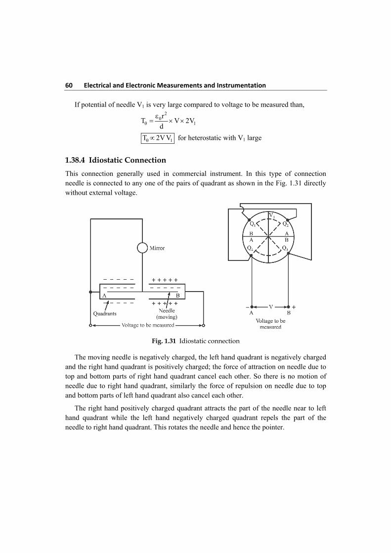
60 Electrical and Electronic Measurements and Instrumentation If potential of needle V1 is very large compared to voltage to be measured than,
2
01
rT V 2V
d
1T 2V V for heterostatic with V1 large
1.38.4 Idiostatic Connection
This connection generally used in commercial instrument. In this type of connection needle is connected to any one of the pairs of quadrant as shown in the Fig. 1.31 directly without external voltage.
Fig. 1.31 Idiostatic connection
The moving needle is negatively charged, the left hand quadrant is negatively charged and the right hand quadrant is positively charged; the force of attraction on needle due to top and bottom parts of right hand quadrant cancel each other. So there is no motion of needle due to right hand quadrant, similarly the force of repulsion on needle due to top and bottom parts of left hand quadrant also cancel each other.
The right hand positively charged quadrant attracts the part of the needle near to left hand quadrant while the left hand negatively charged quadrant repels the part of the needle to right hand quadrant. This rotates the needle and hence the pointer.
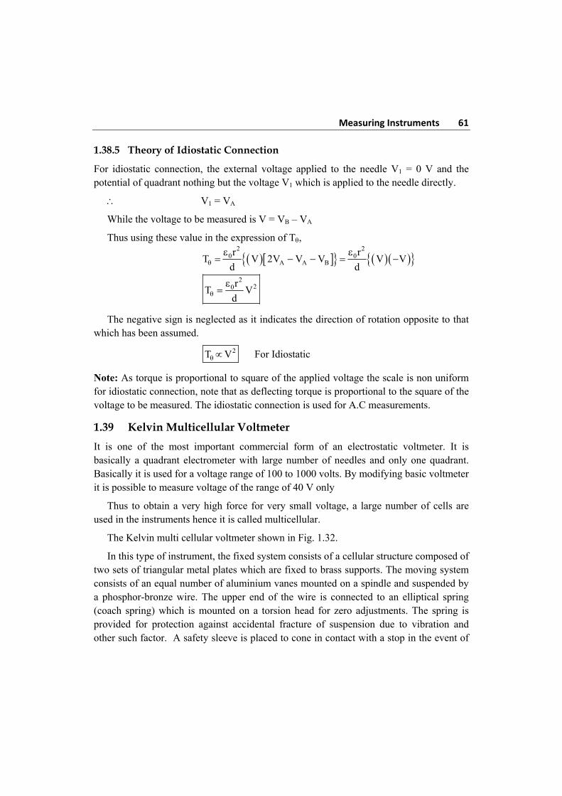
Measuring Instruments 61
1.38.5 Theory of Idiostatic Connection
For idiostatic connection, the external voltage applied to the needle V1 = 0 V and the potential of quadrant nothing but the voltage V1 which is applied to the needle directly.
V1 = VA
While the voltage to be measured is V = VB – VA
Thus using these value in the expression of T,
2 2
0 0A A B
r rT V 2V V V V V
d d
2
20rT V
d
The negative sign is neglected as it indicates the direction of rotation opposite to that which has been assumed.
2T V For Idiostatic
Note: As torque is proportional to square of the applied voltage the scale is non uniform for idiostatic connection, note that as deflecting torque is proportional to the square of the voltage to be measured. The idiostatic connection is used for A.C measurements.
1.39 Kelvin Multicellular Voltmeter
It is one of the most important commercial form of an electrostatic voltmeter. It is basically a quadrant electrometer with large number of needles and only one quadrant. Basically it is used for a voltage range of 100 to 1000 volts. By modifying basic voltmeter it is possible to measure voltage of the range of 40 V only
Thus to obtain a very high force for very small voltage, a large number of cells are used in the instruments hence it is called multicellular.
The Kelvin multi cellular voltmeter shown in Fig. 1.32.
In this type of instrument, the fixed system consists of a cellular structure composed of two sets of triangular metal plates which are fixed to brass supports. The moving system consists of an equal number of aluminium vanes mounted on a spindle and suspended by a phosphor-bronze wire. The upper end of the wire is connected to an elliptical spring (coach spring) which is mounted on a torsion head for zero adjustments. The spring is provided for protection against accidental fracture of suspension due to vibration and other such factor. A safety sleeve is placed to cone in contact with a stop in the event of
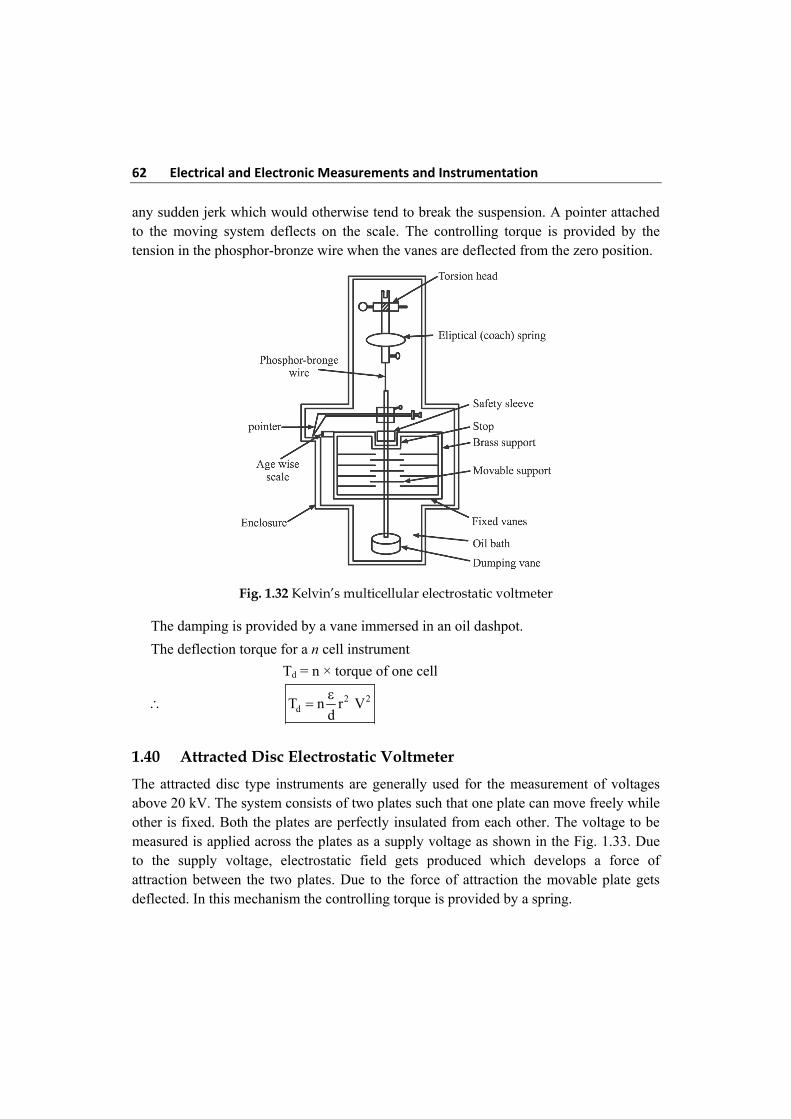
62 Electrical and Electronic Measurements and Instrumentation any sudden jerk which would otherwise tend to break the suspension. A pointer attached to the moving system deflects on the scale. The controlling torque is provided by the tension in the phosphor-bronze wire when the vanes are deflected from the zero position.
Fig. 1.32 Kelvin’s multicellular electrostatic voltmeter
The damping is provided by a vane immersed in an oil dashpot.
The deflection torque for a n cell instrument
Td = n × torque of one cell
2 2dT n r V
d
1.40 Attracted Disc Electrostatic Voltmeter
The attracted disc type instruments are generally used for the measurement of voltages above 20 kV. The system consists of two plates such that one plate can move freely while other is fixed. Both the plates are perfectly insulated from each other. The voltage to be measured is applied across the plates as a supply voltage as shown in the Fig. 1.33. Due to the supply voltage, electrostatic field gets produced which develops a force of attraction between the two plates. Due to the force of attraction the movable plate gets deflected. In this mechanism the controlling torque is provided by a spring.
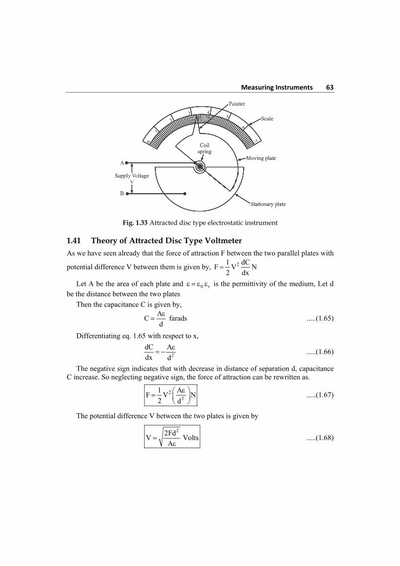
Measuring Instruments 63
Fig. 1.33 Attracted disc type electrostatic instrument
1.41 Theory of Attracted Disc Type Voltmeter
As we have seen already that the force of attraction F between the two parallel plates with
potential difference V between them is given by, 21 dCF V N
2 dx
Let A be the area of each plate and 0 r is the permittivity of the medium, Let d be the distance between the two plates
Then the capacitance C is given by,
A
Cd
farads .....(1.65)
Differentiating eq. 1.65 with respect to x,
2
dC A
dx d
.....(1.66)
The negative sign indicates that with decrease in distance of separation d, capacitance C increase. So neglecting negative sign, the force of attraction can be rewritten as.
22
1 AF V N
2 d
.....(1.67)
The potential difference V between the two plates is given by
22Fd
V VoltsA
.....(1.68)
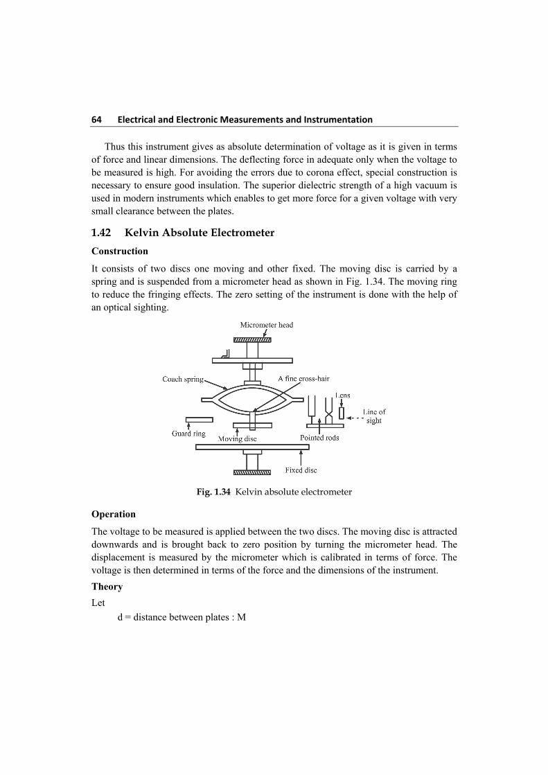
64 Electrical and Electronic Measurements and Instrumentation Thus this instrument gives as absolute determination of voltage as it is given in terms of force and linear dimensions. The deflecting force in adequate only when the voltage to be measured is high. For avoiding the errors due to corona effect, special construction is necessary to ensure good insulation. The superior dielectric strength of a high vacuum is used in modern instruments which enables to get more force for a given voltage with very small clearance between the plates.
1.42 Kelvin Absolute Electrometer
Construction
It consists of two discs one moving and other fixed. The moving disc is carried by a spring and is suspended from a micrometer head as shown in Fig. 1.34. The moving ring to reduce the fringing effects. The zero setting of the instrument is done with the help of an optical sighting.
Fig. 1.34 Kelvin absolute electrometer
Operation
The voltage to be measured is applied between the two discs. The moving disc is attracted downwards and is brought back to zero position by turning the micrometer head. The displacement is measured by the micrometer which is calibrated in terms of force. The voltage is then determined in terms of the force and the dimensions of the instrument.
Theory
Let
d = distance between plates : M
Measuring Instruments 65
A = Area of Plates : M2
= Area of moving plate +1
2 area of air gap between moving plate and guard ring.
= Permittivity of dielectric : F/m
V = voltage being measured : V.
F = Force between disc: N
Force 21 dCF V N
2 dx [from Force eqn instrument] electro static
Let A be the area of each plated and e = 0 r is permittivity of the medium. Let ‘d’ be the distance between the two plates. Then the capacitance C is given by.
A
Cd
farads .....(1.69)
Differentiating eq. 1.69 with respect to x,
2
dC A
dx d
.....(1.70)
The negative sign indicates that with decrease in distance of separation d, capacitance C increase. So neglecting negative sign, the force of attraction can be rewritten as
22
1 AF V N
2 d
.....(1.71)
The potential difference V between the two plates in given by
22Fd
V voltsA
......(1.72)
This instruments gives an absolute determination of potential difference as the potential difference is given in terms of force and linear dimensions. The deflecting force is adequate only when the voltage to be measured is high. For avoiding the errors due to corona effect, special construction is necessary to ensure good insulation. The superior dielectric strength of a high vacuum is used in modern instruments which enable to get more force for a given voltage with very small clearance between the plates.
The disadvantage of this instrument is that when the voltage being measured is small a few hundred (volt the two discs) should be very near together in order to get an appreciable force, in such cases the measurement of distance between the plates is difficult to carry out. The solution lies in increasing the voltage between fixed and moving plates by using hetero static connections.
66 Electrical and Electronic Measurements and Instrumentation 1.43 Advantages and Disadvantages of Electrostatic Instruments
The various advantages of electrostatic instruments are:
1. They can be manufactured with a very high accuracy
2. They can be used on either AC or DC and over a fairly large range frequencies
3. The instrument may be calibrated with DC and yet the calibration would be valid for AC also since the deflection is independent of the waveform of the applied voltage
4. Since no iron is used for their construction. They are free from hysteresis, eddy current losses and temperature errors.
5. Their power losses in negligible
6. They are unaffected by stray magnetic field although they have to be guarded against any stray electrostatic field.
7. They can be used up to 100 kHz frequency without any serious loss of accuracy.
8. Once the discs are charged, no more current is drawn from the circuit and the instruments represents infinite impendence.
Disadvantages
1. The scale is not uniform
2. These are large in size, bulky and not very robust
3. They are not suitable for low voltage measurements
4. These are expensive instruments.
Limitations of Electrostatic Instruments
1. Low voltage Voltmeter are liable to friction errors.
2. Since the deflection torque is proportional to the square of the voltage, their scales are not uniform although some uniformity can be obtained by suitably shaping the quadrants of the Instruments.
3. Their use is limited to certain special application particularly in A.C. circuits of relatively high voltage where the current taken by other instruments would result in erroneous indications.
4. They are inherently, Laboratory-type rather than industrial-type instruments.
5. They are expensive and are not likely to be durable.
1.44 Extension of Range of Electrostatic Voltmeter
The range of various instruments can be extended using multipliers. Similarly the range of electrostatic instruments is also extended using multipliers. The multipliers used for electrostatic instruments are of two types:
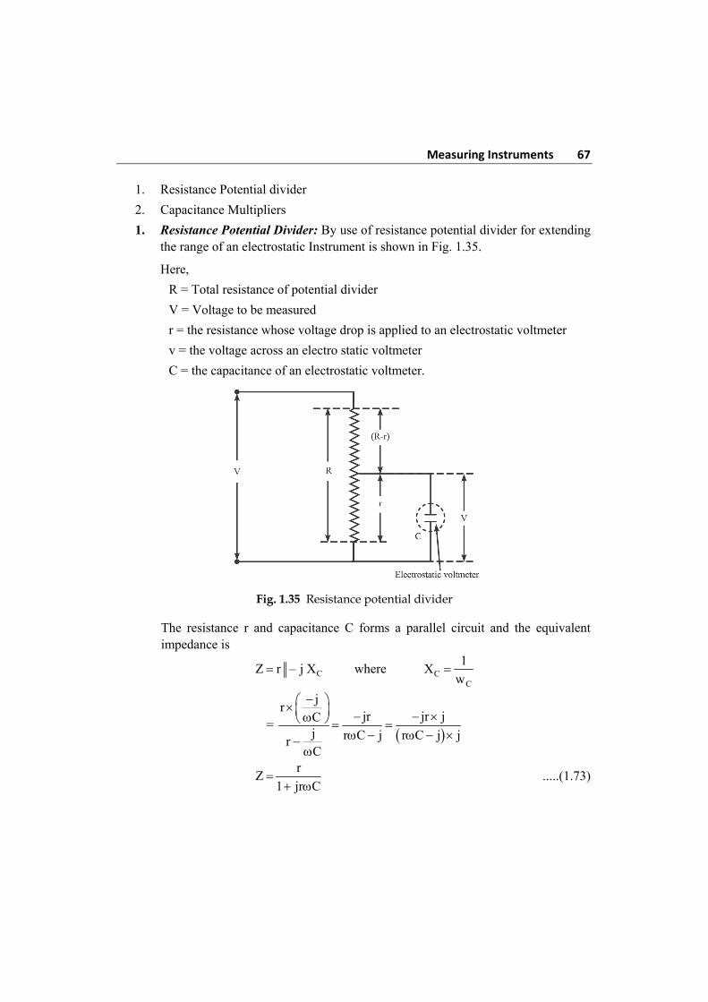
Measuring Instruments 67
1. Resistance Potential divider
2. Capacitance Multipliers
1. Resistance Potential Divider: By use of resistance potential divider for extending the range of an electrostatic Instrument is shown in Fig. 1.35.
Here,
R = Total resistance of potential divider
V = Voltage to be measured
r = the resistance whose voltage drop is applied to an electrostatic voltmeter
v = the voltage across an electro static voltmeter
C = the capacitance of an electrostatic voltmeter.
Fig. 1.35 Resistance potential divider
The resistance r and capacitance C forms a parallel circuit and the equivalent impedance is
CZ r – j X where CC
1X
w
=
jr
jr jr jCj r C j r C j jrC
r
Z1 jr C
.....(1.73)
68 Electrical and Electronic Measurements and Instrumentation Thus the equivalent independence across the voltage V is,
ZT = R – r + Z
=
R r 1 jr C rr
R r1 jr C 1 jr C
T
R j rC R rZ
1 jr C
.....(1.74)
The factor by which voltage is charged due to potential divider is called its multiplying power and given by
T
R j rC R r
1 jr CZVm
v z r /1 jr C
R j rC R r R
m j C R rr r
.....(1.75)
The numerical value of multiplying power m is
2
22 2Rm C R r
r
.....(1.76)
If , ‘C’ and ‘r’ are very small then w2C2r2 1 and can be neglected.
22 2 2
2
C r R rR Rm 1
r rR
......(1.77)
This can be easily analyzed 1. At high voltages, the accuracy is very less due to stray capacitance effects. 2. When used for A.C measurements, it should be wound non inductively and
capacitor leakage resistance must be high. 3. At high voltage, the power losses and wastage is excessive, high cost.
Thus this method is not suitable for high voltages but used for D.C measurements as capacitance potential divider cannot be used for D.C. circuits.
2. Capacitance Multipliers: The capacitance multiplier method is nothing but the use of capacitance potential divider. There are two methods of connecting capacitor for potential division.
Method I: In this method a single capacitor is connected in series with the voltmeter and the voltmeter to be measured and applied across the combination as shown in Fig. 1.36.
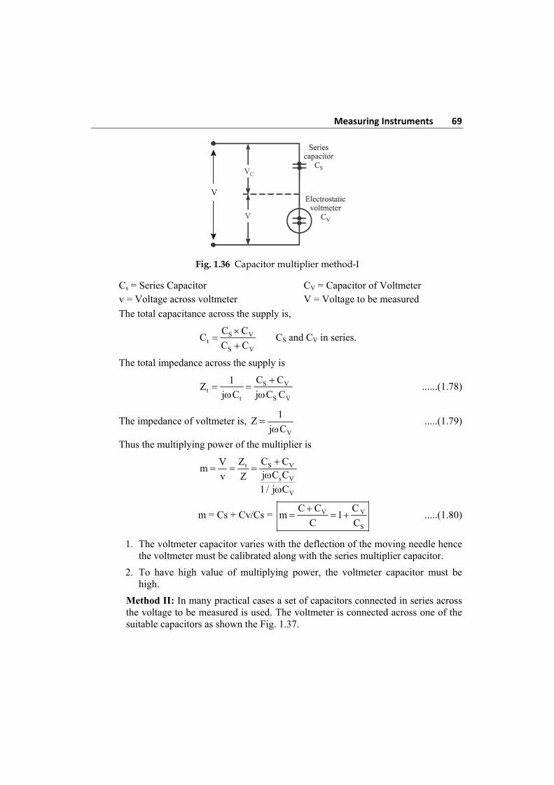
Measuring Instruments 69
Fig. 1.36 Capacitor multiplier method-I
Cs = Series Capacitor CV = Capacitor of Voltmeter v = Voltage across voltmeter V = Voltage to be measured
The total capacitance across the supply is,
S Vt
S V
C CC
C C
CS and CV in series.
The total impedance across the supply is
S Vt
t S V
C C1Z
j C j C C
......(1.78)
The impedance of voltmeter is, V
1Z
j C
.....(1.79)
Thus the multiplying power of the multiplier is
t S V
s V
V
Z C CVm
j C Cv Z1/ j C
m = Cs + Cv/Cs = V V
S
C C Cm 1
C C
.....(1.80)
1. The voltmeter capacitor varies with the deflection of the moving needle hence the voltmeter must be calibrated along with the series multiplier capacitor.
2. To have high value of multiplying power, the voltmeter capacitor must be high.
Method II: In many practical cases a set of capacitors connected in series across the voltage to be measured is used. The voltmeter is connected across one of the suitable capacitors as shown the Fig. 1.37.
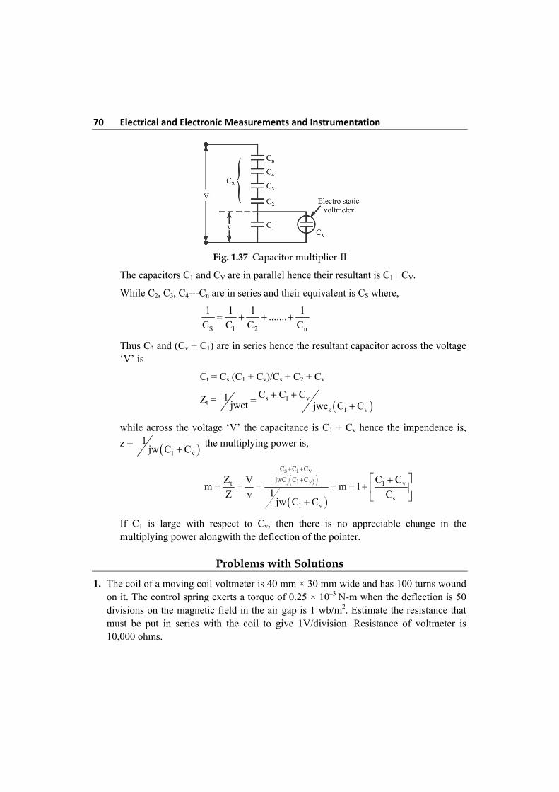
70 Electrical and Electronic Measurements and Instrumentation
Fig. 1.37 Capacitor multiplier-II
The capacitors C1 and CV are in parallel hence their resultant is C1+ CV.
While C2, C3, C4---Cn are in series and their equivalent is CS where,
S 1 2 n
1 1 1 1.......
C C C C
Thus C3 and (Cv + C1) are in series hence the resultant capacitor across the voltage ‘V’ is
Ct = Cs (C1 + Cv)/Cs + C2 + Cv
Zt = s 1 v
s 1 v
C C C1jwct jwc C C
while across the voltage ‘V’ the capacitance is C1 + Cv hence the impendence is,
z = 1 v
1jw C C the multiplying power is,
C C Cs 1 vjwC C Cj 1 v)t 1 v
s1 v
Z C CVm m 1
1Z v Cjw C C
If C1 is large with respect to Cv, then there is no appreciable change in the multiplying power alongwith the deflection of the pointer.
Problems with Solutions
1. The coil of a moving coil voltmeter is 40 mm × 30 mm wide and has 100 turns wound on it. The control spring exerts a torque of 0.25 × 10⁻³ N-m when the deflection is 50 divisions on the magnetic field in the air gap is 1 wb/m2. Estimate the resistance that must be put in series with the coil to give 1V/division. Resistance of voltmeter is 10,000 ohms.
Measuring Instruments 71
Solution:
Given data:
Number of turns, N = 100
Controlling torque Tc = 0.25 × 10⁻³ N-m
Deflection, = 50 scale divisions
Dimensions of the coil = 40 mm × 30 mm (l × d)
Flux density in the air gap, B = 1 wb/m2
Required voltage per division = 1 V / division
Resistance of voltmeter, Rm = 10,000
Series resistance Rse = ?
The deflecting torque is
Td = NBldI N-m
= 100 × 1 × 40 × 10–3 × 30 × 10–3 × I
= 0.12 I N-m
The controlling torque is
Tc = k
= 0.25 × 10⁻³ N-m
At equilibrium or steady state conditions, the controlling torque is equal to deflecting torque
Tc = Td
0.25 × 10–3 = 0.12 I
3
30.25 10I 2.083 10 A
0.12
Therefore current at full scale deflection, I = 2.083 mA
Let, the resistance to be added in series with the coil be ‘Rse’
The resistance of the voltmeter in circuit = se mR R
The voltage across the instrument = current at full scale division × resistance of the voltmeter in circuit.
3m se seI(R R ) 2.083 10 (10000 R )
3se20.83 2.083 10 R
This produces a deflection of 50 divisions
72 Electrical and Electronic Measurements and Instrumentation
voltage across instrument
Volts per division = no. of divisions
3
se20.83 2.083 10 RV / division
50
3
se20.83 2.083 10 R1
50
20.83 + 2.083 × 10⁻³ Rse = 50 Rse = 14000 Ans.
A resistance of 14000 or 14 k must be added in series with the coil to obtain 1V/division
2. In a measurement of resistance by the substitution method, a standard resistance of 100 k is used. The galvanometer has a resistance of 2000 and given the following deflections.
(i) With unknown resistance, 46 divisions
(ii) With standard ‘R’, 40 divisions
Find value of the unknown resistance
Solution:
Given data:
Standard ‘R’, S = 100 k
Galvonometer ‘R’, G = 2 k
Deflection with standard ‘r’, 1 = 40 division
Deflection with unknown ‘r’, 2 = 46 division
Unknown resistance, x = ?
The deflection of the galvanometer is directly proportional to the I passing through the circuit and, I is inversely proportional to the resistance of the circuit.
1
IR
From substion method, analysis, 1
2
X G
S G
1
2
X G (S G)
Measuring Instruments 73
unknown ‘R’, 1
2
X (S G) G
40
(100 k 2 k ) (2000)46
= 86.69 k Ans.
3. In the moving coil voltmeter, Resistance = 10 k dimensions of coil = 30 mm × 30 mm, no.of turn of coil = 100, flux density in the air gap = 0.08 wb/m2 and spring constant = 3 × 10⁻⁶ N-m per degree. Find the deflection produced by a voltage of 200 V.
Solution:
Given data:
R = 10 k A = 30 × 30 × 10–6 m2
N = 100
B = 0.08 wb/m2, k = 3 × 10⁻⁶ N-m / deg.
V = 200V
Find = ?
dT NBI(L d)
= NBIA
But V 200
I 20 mAR 10K
6 3dT 100 0.08 30 30 10 20 10 .....(1)
= 144 × 10–6 N-m
Controlling torque Tc = k
Tc = 3 × 10⁻⁶ .....(2)
For equilibrium condition
eq. (1) = eq. (2)
6 6d cT T 144 10 3 10
6
6
144 10
3 10
∴ oθ = 48 Ans.
74 Electrical and Electronic Measurements and Instrumentation 4. In a moving coil instrument, the coil is wound with 50 turns in square section former
of mean length 4 cm long each side. The coil charge in a uniform radial field of 0.08 wb/m2. Find the torque produced in it.
Solution:
Torque = ?
F = NBil Newton
Torque = Force × Width
= NBil × width
= NBil2 N-m
= 50 × 0.08 × 10 × 10–3 × 0.042
T = 6.4 × 10⁻⁴ N-m Ans.
5. Calculate the shunt required to extent the range up to 10A when it gives full scale deflection with a current of 50 mA. The resistance of the coil is 0.08 .
Solution:
Total current to be measured = 10 A
Instrument current = 50 mA = 0.05 A
Multiplying power = m
I 10200
I 0.05
Resistance of shunt = ms
RR
M 1
0.08 0.08
200 1 199
4 × 10⁻⁴ Ans.
6. Moving coil instrument whose resistance is 2.5 gives full scale deflection with a current of 1 mA. This instrument is to be used with a manganin shunt to extent its range to 100 mA. Calculate the error caused by a 10 oC rise in temperature when,
(i) Copper moving coil is connected directly
(ii) A 75 manganin resistance is used in series with the instrument moving coil.
The temperature coefficient of copper is 0.004/oC and that of manganin is 0.00015 / oC
Solution:
Given data:
Resistance of instrument mR 25
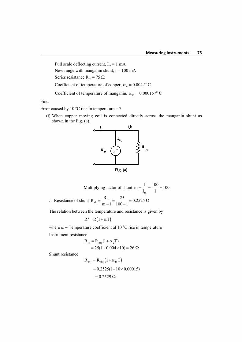
Measuring Instruments 75
Full scale deflecting current, Im = 1 mA
New range with manganin shunt, I = 100 mA
Series resistance Rse = 75
Coefficient of temperature of copper, oc 0.004 / C
Coefficient of temperature of manganin, om 0.00015 / C
Find
Error caused by 10 oC rise in temperature = ?
(i) When copper moving coil is connected directly across the manganin shunt as shown in the Fig. (a).
Fig. (a)
Multiplying factor of shunt m
I 100m 100
I 1
Resistance of shunt msh
R 25R 0.2525
m 1 100 1
The relation between the temperature and resistance is given by
R ' R 1 T
where = Temperature coefficient at 10 oC rise in temperature
Instrument resistance
'm m c1
R R (1 T)
25(1 0.004 10) 26
Shunt resistance sh sh m1 1
R R 1 T
0.2525(1 10 0.00015)
= 0.2529
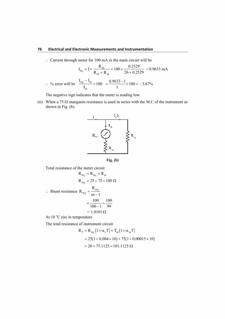
76 Electrical and Electronic Measurements and Instrumentation Current through meter for 100 mA in the main circuit will be
'sh
m ' '1sh sn
R 0.2529I I 100
26 0.2529R R
= 0.9633 mA
% error will be m m1
m
I I100
I
0.9633 1100 – 3.67%
1
The negative sign indicates that the meter is reading low.
(ii) When a 75 manganin resistance is used in series with the M.C of the instrument as shown in Fig. (b).
Fig. (b)
Total resistance of the meter circuit m m se2 1
R R R
m2R 25 75 100
Shunt resistance m2
sh2
RR
m 1
100 100
100 1 99
= 1.0101 At 10 oC rise in temperature
The total resistance of instrument circuit
T m c se m1R R 1 T T 1 T
25 1 0.004 10 75 1 0.00015 10
26 75.1125 101.1125
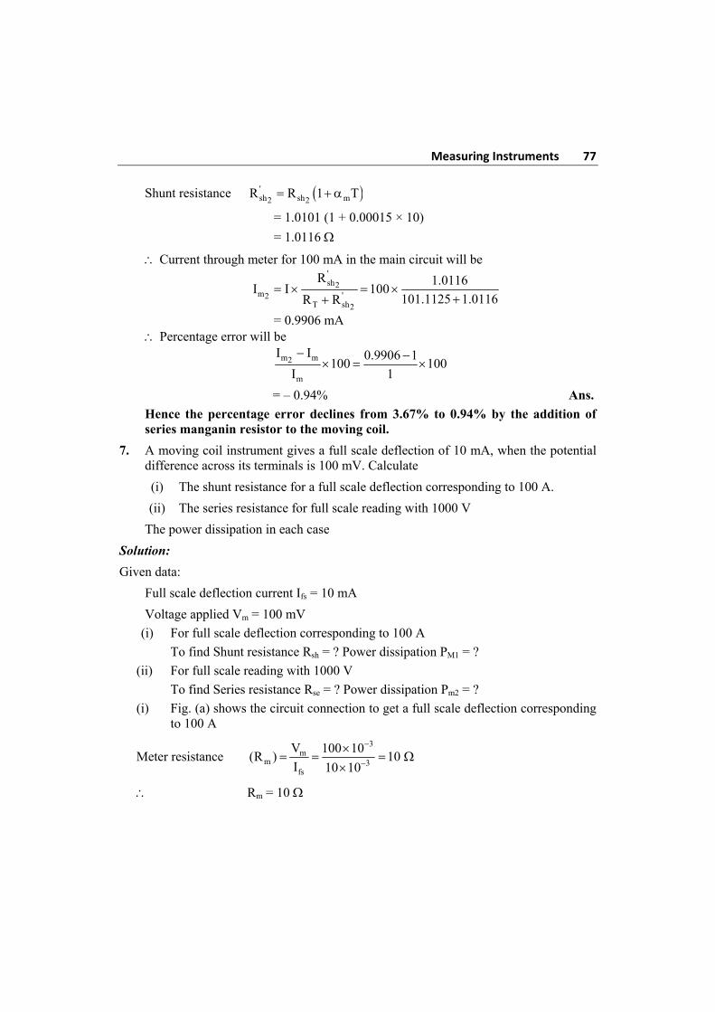
Measuring Instruments 77
Shunt resistance 'sh sh m2 2
R R 1 T
= 1.0101 (1 + 0.00015 × 10)
= 1.0116
Current through meter for 100 mA in the main circuit will be
'sh2
m '2T sh2
R 1.0116I I 100
101.1125 1.0116R R
= 0.9906 mA Percentage error will be
m m2
m
I I 0.9906 1100 100
I 1
= – 0.94% Ans.
Hence the percentage error declines from 3.67% to 0.94% by the addition of series manganin resistor to the moving coil.
7. A moving coil instrument gives a full scale deflection of 10 mA, when the potential difference across its terminals is 100 mV. Calculate
(i) The shunt resistance for a full scale deflection corresponding to 100 A.
(ii) The series resistance for full scale reading with 1000 V
The power dissipation in each case
Solution:
Given data:
Full scale deflection current Ifs = 10 mA
Voltage applied Vm = 100 mV
(i) For full scale deflection corresponding to 100 A
To find Shunt resistance Rsh = ? Power dissipation PM1 = ?
(ii) For full scale reading with 1000 V
To find Series resistance Rse = ? Power dissipation Pm2 = ?
(i) Fig. (a) shows the circuit connection to get a full scale deflection corresponding to 100 A
Meter resistance 3
mm 3
fs
V 100 10(R ) 10
I 10 10
Rm = 10
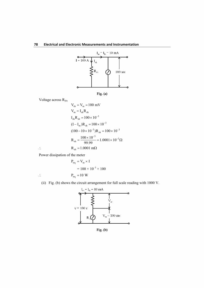
78 Electrical and Electronic Measurements and Instrumentation
Fig. (a)
Voltage across Rsh, sh mV V 100 mV
m sh shV I R
3sh shI R 100 10
3m sh(I I )R 100 10
3 3sh(100 10 10 )R 100 10
3
3sh
100 10R 1.0001 10
99.99
shR 1.0001 m
Power dissipation of the meter
m m1P V I
= 100 × 10–3 × 100
m1P 10 W
(ii) Fig. (b) shows the circuit arrangement for full scale reading with 1000 V.
Fig. (b)
Measuring Instruments 79
Voltage across Rse, se mV V V
3m seI R 1000 (100 10 )
3se10 10 R 999.9
se 3
999.9R 99990
10 10
seR 99.99 k
The power dissipation of the meter
m m2P V I
3m2
P 1000 10 10 10 W
8. The measured value of a resistor is 105 where as its true value is 100 . Determine the relative error.
Solution:
Measured value, Am = 105
True value, A = 100
Absolute error, 0 mA A 105 100
= 5
Relative error, 0r
50.05
A 100
Percentage error = 5
9. In a moving coil instrument, the moving coil consists of 100 turns wound on a square former coil length 3 cm. The flux density in the air gap is 0.06 T. Calculate the turning movement acting on the coil when carrying a current of 12 mA.
Solution:
Given data:
Number of turns on the coil N = 100
Mean length of the coil, l = 3 cm = 0.03 m
Flux density in the air gap B = 0.06 T
Current flowing through the coil i = 0.012 A
The deflecting force F = BilN
= 0.06 × 0.012 × 0.03 × 100 = 0.00216 N
80 Electrical and Electronic Measurements and Instrumentation Distance between the centres of the sides of coil
2r = width of the former = 0.03 m
Turning movement acting on the coil = F × 2r
= 0.00216 × 0.03
= 648 × 10–7 N-m Ans.
Note: The flux density may be also given as 0.06 b/m2 (1T = 1b/m2)
10. The inductance of a moving iron instrument is given by inductance
L = 2(10 5 ) H . Where is the deflection in radian from zero position. The
spring constant is 12 × 10–6 Nm/rad. Estimate the deflection for a current of 5 amps.
Solution:
Given data:
Inductance L = 210 5 H
Spring constant K = 12 × 10–6 Nm/rad
Current I = 5 A
Deflection = ?
The rate of change of inductance with deflection
dL
5 2 H / radd
We know that in case of M.I instruments,
Deflection,
21 I dL
2 K d
2
66
1 (5)(5 2 ) 10
2 12 10
1.0416(5 2 )
5.20833 2.0833
3.0833 5.20833
1.689 rad or
= 96.78o Ans.
11. The following data refers to a moving coil voltmeter: resistance = 10.000 , dimensions of coil = 30 mm × 30 mm, number of turns of coil = 100, flux density in
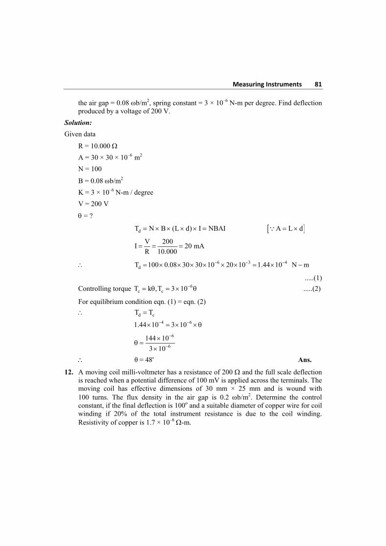
Measuring Instruments 81
the air gap = 0.08 b/m2, spring constant = 3 × 10⁻⁶ N-m per degree. Find deflection produced by a voltage of 200 V.
Solution:
Given data
R = 10.000
A = 30 × 30 × 10–6 m2
N = 100
B = 0.08 b/m2
K = 3 × 10⁻⁶ N-m / degree
V = 200 V
= ?
dT N B (L d) I NBAI A L d
V 200
I 20 mAR 10.000
6 3 4dT 100 0.08 30 30 10 20 10 1.44 10 N m
.....(1)
Controlling torque 6c cT k ,T 3 10 .....(2)
For equilibrium condition eqn. (1) = eqn. (2)
d cT T
4 61.44 10 3 10
6
6
144 10
3 10
θ = 48' Ans.
12. A moving coil milli-voltmeter has a resistance of 200 and the full scale deflection is reached when a potential difference of 100 mV is applied across the terminals. The moving coil has effective dimensions of 30 mm × 25 mm and is wound with 100 turns. The flux density in the air gap is 0.2 b/m2. Determine the control constant, if the final deflection is 100o and a suitable diameter of copper wire for coil winding if 20% of the total instrument resistance is due to the coil winding. Resistivity of copper is 1.7 × 10⁻⁸ -m.
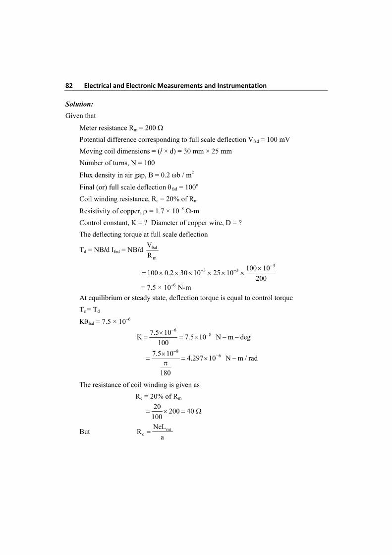
82 Electrical and Electronic Measurements and Instrumentation Solution:
Given that
Meter resistance Rm = 200
Potential difference corresponding to full scale deflection Vfsd = 100 mV
Moving coil dimensions = (l × d) = 30 mm × 25 mm
Number of turns, N = 100
Flux density in air gap, B = 0.2 b / m2
Final (or) full scale deflection fsd = 100o
Coil winding resistance, Rc = 20% of Rm
Resistivity of copper, = 1.7 × 10⁻⁸ -m
Control constant, K = ? Diameter of copper wire, D = ?
The deflecting torque at full scale deflection
Td = NBld Ifed = NBld fsd
m
V
R
3
3 3 100 10100 0.2 30 10 25 10
200
= 7.5 × 10⁻⁶ N-m
At equilibrium or steady state, deflection torque is equal to control torque
Tc = Td
Kfsd = 7.5 × 10⁻⁶
6
87.5 10K 7.5 10 N m deg
100
8
67.5 104.297 10 N m / rad
180
The resistance of coil winding is given as
Rc = 20% of Rm
20
200 40 100
But mtc
NeLR
a
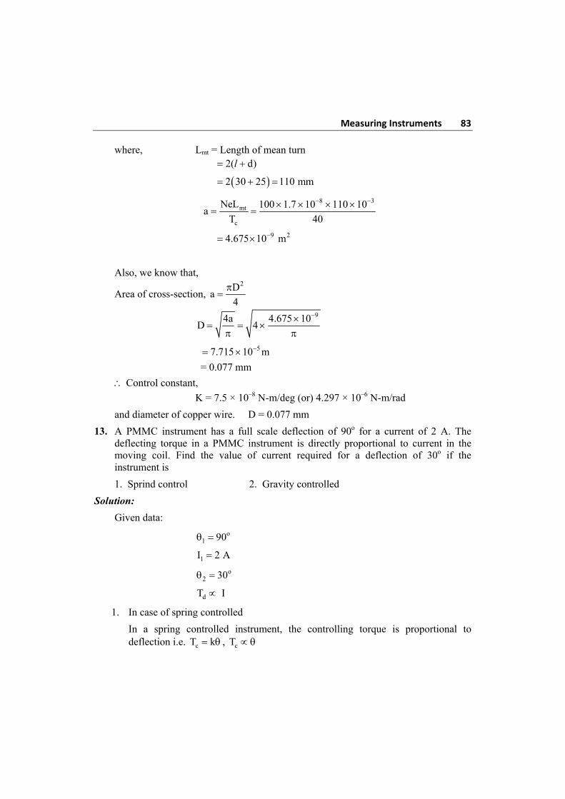
Measuring Instruments 83
where, Lmt = Length of mean turn 2( d) l
2 30 25 110 mm
8 3
mt
c
NeL 100 1.7 10 110 10a
T 40
9 24.675 10 m
Also, we know that,
Area of cross-section, 2D
a4
94a 4.675 10
D 4
57.715 10 m
= 0.077 mm
Control constant,
K = 7.5 × 10⁻⁸ N-m/deg (or) 4.297 × 10⁻⁶ N-m/rad
and diameter of copper wire. D = 0.077 mm
13. A PMMC instrument has a full scale deflection of 90o for a current of 2 A. The deflecting torque in a PMMC instrument is directly proportional to current in the moving coil. Find the value of current required for a deflection of 30o if the instrument is
1. Sprind control 2. Gravity controlled
Solution:
Given data:
o1 90
1I 2 A
o2 30
dT I
1. In case of spring controlled
In a spring controlled instrument, the controlling torque is proportional to deflection i.e. cT k , cT
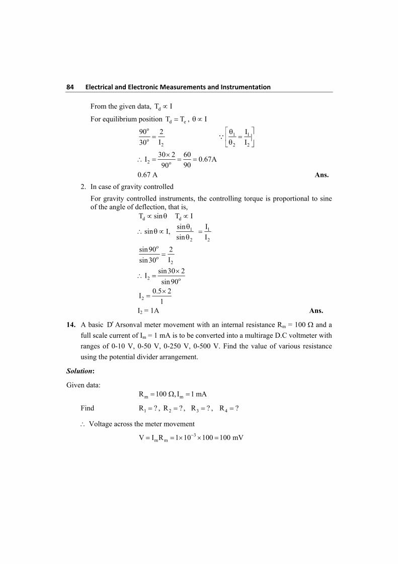
84 Electrical and Electronic Measurements and Instrumentation From the given data, dT I
For equilibrium position d eT T , I
o
o2
90 2
I30 1 1
2 2
I
I
2 o
30 2 60I 0.67A
9090
0.67 A Ans.
2. In case of gravity controlled
For gravity controlled instruments, the controlling torque is proportional to sine of the angle of deflection, that is,
d dT sin T I
1 1
2 2
sin Isin I,
sin I
o
o2
sin90 2
Isin30
2 o
sin30 2I
sin 90
20.5 2
I1
I2 = 1A Ans.
14. A basic DArsonval meter movement with an internal resistance Rm = 100 and a
full scale current of Im = 1 mA is to be converted into a multirage D.C voltmeter with
ranges of 0-10 V, 0-50 V, 0-250 V, 0-500 V. Find the value of various resistance
using the potential divider arrangement.
Solution:
Given data: m mR 100 , I 1 mA
Find 1R ? , 2R ? , 3R ? , 4R ?
Voltage across the meter movement
3m mV I R 1 10 100 100 mV
Measuring Instruments 85
Voltage multiplying factors
1 3
10M 100
100 10
2 3
50M 500
100 10
3 3
250M 2500
100 10
4 3
500M 5000
100 10
Let R1, R2, R3, R4 be the values of resistance for the voltmeter with ranges 0-10, 0-5,
0-250, 0-500, respectively.
1 1 mR (M 1)R (100 1) 100 9900 9.9 K
2 2 1 mR (M M )R (500 100) 100 40 K
3 3 2 mR (M M )R (2500 500) 100 200 K
4 4 3 mR (M M )R (5000 2500) 100 250 K
Review Questions
1. How the various measuring instruments are classified? What are the basic requirements of any measuring instruments?
2. State the various effects with which deflecting torque is produced?
3. State the difference between spring control and gravity control methods to produce control Torque?
4. Explain various methods of providing damping torque in an indicating instrument.
5. What are the essentials of indicating instruments?
6. Write a short note on controlling system.
7. Write a short note on Damping systems.
8. Write the advantages and Disadvantages of PMMC.
9. Derive the Torque equation of DArsonval galvanometer?
10. Explain Dynamic behaviour of Galvonometer?
11. Explain – Intrinsic constants of DArsenal galvanometer.
86 Electrical and Electronic Measurements and Instrumentation 12. Explain – under damped, over damped, critically damped motions in D’Arsonval
galvanometer?
13. Explain about logarithmic decrement in galvanometer.
14. Explain effect of External resistance on Damping and derive the value of critical resistance for damping.
15. Write a short not on sensitivity of galvanometer?
16. Explain briefly errors in moving coil instruments?
17. Derive the Torque equation of Moving Iron Instruments?
18. Explain with a neat sketch about 1. Radial vane repulsion 2. Concentric vane Repulsion Type Instruments?
19. What are the advantages and disadvantages of M.I. Instruments?
20. State and explain each in briefly errors in M.I. Instrument
21. State the comparison between moving coil and Moving Iron Instrument
22. What are the requirements of a shunt? The aryton shunt
23. What are the precautions to be taken while using as an ammeter
24. Write short note on 1. Basic DC. Ammeter 2. Basic D.C voltmeter
25. What are the precautions to be taken while a volt meter?
26. What is loading effect?
27. Describe the construction and working of PMMC instrument
28. Derive Torque equation for PMMC.
29. State the errors in PMMC instruments.
30. What are requirements of shunts and multiplyers?
31. Write a short note on (i) Kelvin multicellular voltmeter (ii) Kelvin absolute electrometer.
32. List the advantages and Disadvantages of electrostatic instruments.
33. Explain attracted-disc type electrometer with neat diagram.
34. Explain principle of electrostatic instrument.
35. Explain briefly quadrant type electrometer.
Quiz Questions
1. The most effective damping is
(a) fluid friction (b) eddy current
(c) pneumatic (d) electromagnetic
Measuring Instruments 87
2. A 0-100 V range voltmeter has sensitivity 1000 /volt. Its internal resistance is:
(a) 1000 (b) 10,000
(c) 100 k (d) 1000 k
3. The moving iron instruments can be used for measuring
(a) direct current and voltages (b) AC current and voltages
(c) both (a) and (b) (d) radio frequency current
4. The meter that is suitable for only direct current measurement is:
(a) MI type (b) hot-wire
(c) electro dynamic type (d) PMMC
5. In MI instrument, the deflecting torque is proportional to
(a) I3 (b) ‘I’ (c) I3/2 (d) I2
6. Indicating Instruments measure:
(a) peak value (b) RMS value
(c) average value (d) none
7. In MC ammeter scale on the dial is
(a) cramped at the beginning (b) cramped in middle
(c) cramped at end (d) uniform throughout
8. The following meter reads DC ‘voltage’ and current accurately.
(a) moving iron (b) PMMC
(c) dynamometer (d) none
9. The moving coil in a dynamometer wattmeter is connected
(a) across the supply (b) in series with the fixed coil
(c) in series with the load (d) across the load
10. A dynamometer type wattmeter responds to time
(a) average value of active power (b) average of reactive power
(c) peak value of active power (d) peak value of reactive power
11. Two 100 A full scale PMMC meters are employed to construct a 10 V and a 100 V full scale voltmeter. These meters will have figures of merit (sensitises)
(a) 100 k/V and 10 k/V (b) 100 k/V and 1 k/V
(c) 10 k/V and 100 k/V (d) 10 k/V and 1 k/V
88 Electrical and Electronic Measurements and Instrumentation 12. A 0-10 mA PMMC ammeter reads 4 mA in a circuit. Its bottom control spring
shapes suddenly, the meter will now read nearly.
(a) 10 mA (b) 8 mA
(c) 2 mA (d) zero
13. The scale of moving iron type instrument
(a) cramped at the beginning (b) cramped at end
(c) cramped in the middle (d) uniform throughout
14. In a moving coil instrument the scale on dial is
(a) uniform throughout (b) cramped at the beginning
(c) cramped at middle (d) cramped at the end
15. For repulsion type MI instruments
(a) air friction (b) pneumatic
(c) eddy correct (d) fluid friction
16. Which of the following instrument has the best accuracy
(a) moving coil (b) moving iron
(c) hot wire (d) thermal
17. The most effective damping is
(a) fluid friction (b) electromagnetic
(c) pneumatic (d) eddy current
18. A 25% error voltmeter is used to measure supply voltage of 100 V (DC). The meter reads
(a) 125 V (b) 75 V
(c) 100 V (d) 150 V
19. The kwh meter can be classified as an ..................... instrument
(a) deflecting (b) digital
(c) recording (d) indicating
20. The damping type used in moving iron instruments
(a) air friction (b) pneumatic
(c) eddy current (d) fluid friction
21. The disadvantage of permanent magnet moving coil instrument is
(a) high power consumption
(b) high cost relative to moving iron instrument
Measuring Instruments 89
(c) low torque / weight ratio
(d) absence of effective and efficient eddy current damping
22. When an ac voltage is applied to a PMMC voltmeter
(a) the meter gets damped (b) meter reading is zero
(c) pointer will oscillate to and fro (d) the pointer will not move at all
23. Error which does not result in moving iron instrument for both ac and dc measurement
(a) stray magnetic field error (b) hysterisis error
(c) eddy current error (d) temperature error
24. The power consumption of PMMC instruments is typically about
(a) 0.25 W to 2 W (b) 25 W to 200 W
(c) 0.25 mW to 2 mW (c) None
25. In an induction type of meter, maximum torque is produced when the phase angle, between the two fluxes is
(a) 0o (b) 45o
(c) 60o (d) 90o
26. In induction type of instrument
(a) 2dT I (b) dT T
(c) dT sin (d) 'dT I
27. The main problem with bar-graph meters is that
(a) they are not very sensitive
(b) they are unstable
(c) they cannot give very precise readings
(d) they can display only peak values
28. The meter movement in an illumination meter directly measures
(a) current (b) power
(c) voltage (d) energy
29. Ammeter shunts are useful because
(a) they prevent overheating of the meter movement
(b) they make a meter more physically rugged
(c) they allow for measurement of large currents
(d) they increase meter sensitivity
90 Electrical and Electronic Measurements and Instrumentation 30. Suppose a certain current in a galvanometer causes the compass needle to deflect by
20 degree, then this current is doubled while the polarity stays the same. The angle of the needle deflection will
(a) reverse direction (b) stay the same
(c) increase (d) decrease
31. A hot-wire ammeter
(a) Can measure ac as well as dc
(b) Registers current changes very fast
(c) Can indicate very low voltages
(d) Measures electrical energy
32. Which of the following types of instrument is an integrating instrument
(a) P.F meter (b) energy meter
(c) Watt meter (d) frequency meter
33. Direct method is used to measure
(a) Length (b) temperature
(c) Pressure (d) voltage
34. Which instrument has the lowest resistance?
(a) ammeter (b) voltmeter
(c) frequency meter (d) negger
35. The best material of use for standard resistor is
(a) manganin (b) aluminium
(c) nichronme (d) platinum
36. Which of the following is absolute instrument
(a) power facter-meter (b) tangent galvanometer
(c) megger (d) frequency meter
37. The pointer in instrument is made up of
(a) steel (b) iron
(c) aluminum (d) copper
38. Ampere is one of the
(a) supplementary unity (b) derived units
(c) base units (d) units used to measure change
Measuring Instruments 91
39. In moving system instruments the damping force is used to
(a) brings the pointer to rest (Zero) position
(b) move the pointer from its zero position
(c) uniform movement of pointer
(d) none of the above
Questions and Answers
1. What is meant by measurement?
Ans. Measurement is an act or the result of comparison between the quantity and a predefined standard.
2. Mention the basic requirements of measurement.
Ans. The standard used for comparison purpose must be accurately defined and should be commonly accepted. The apparatus used and the method adopted must be provable.
3. What are the 2 methods for measurement?
Ans. Direct method and Indirect method.
4. Explain the function of measurement system.
Ans. The measurement system consists of a transducing element which converts the quantity to be measured in an analogous form. The analogous signal is then processed by some intermediate means and is then fed to the end device which presents the results of the measurement.
5. Define Instrument.
Ans. Instrument is defined as a device for determining the value or magnitude of a quantity or variable.
6. List the types of instruments.
Ans. The 3 types of instruments are:
1. Mechanical Instruments
2. Electrical Instruments and
3. Electronic Instruments.
7. Classify instruments based on their functions.
Ans. Indicating instruments
Integrating instruments
Recording instruments
92 Electrical and Electronic Measurements and Instrumentation 8. Give the applications of measurement systems.
Ans. The instruments and measurement systems are used for Monitoring of processes and operations, Control of processes and operations, experimental engineering analysis.
9. Why calibration of instrument is important?
Ans. The calibration of all instruments is important since it affords the opportunity to check the instrument against a known standard and subsequently to errors in accuracy.
10. Name the different essential torques in indicating instruments.
Ans. Deflecting torque
Controlling torque
Damping torque
11. Name the types of instruments used for making voltmeter and ammeter.
Ans. PMMC type
Moving iron type
Dynamometer type
Hot wire type
Electrostatic type
Induction type.
12. State the advantages of PMMC instruments
Ans. Uniform scale.
No hysterisis loss
Very accurate
High efficiency.
13. State the disadvantages of PMMC instruments
Ans. Cannot be used for ac measurements
Some errors are caused by temperature variations.
14. How the range of instrument can be extended in PMMC instruments.
Ans. In ammeter by connecting a shunt resister
In voltmeter by connecting a series resister.
15. State the advantages of Dynamometer type instruments
Ans. Can be used for both dc and ac measurements.
Free from hysterisis and eddy current errors.
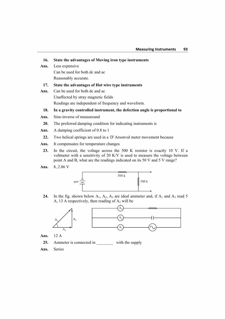
Measuring Instruments 93
16. State the advantages of Moving iron type instruments
Ans. Less expensive
Can be used for both dc and ac
Reasonably accurate.
17. State the advantages of Hot wire type instruments
Ans. Can be used for both dc and ac
Unaffected by stray magnetic fields
Readings are independent of frequency and waveform.
18. In a gravity controlled instrument, the defection angle is proportional to
Ans. Sine-inverse of measureand
20. The preferred damping condition for indicating instruments is
Ans. A damping coefficient of 0.8 to 1
22. Two helical springs are used in a DArsonval meter movement because
Ans. It compensates for temperature changes
23. In the circuit, the voltage across the 500 K resistor is exactly 10 V. If a voltmeter with a sensitivity of 20 K/V is used to measure the voltage between point A and B, what are the readings indicated on its 50 V and 5 V range?
Ans. 8, 2.86 V
24. In the fig. shown below A1, A2, A3 are ideal ammeter and, if A1 and A3 read 5
A, 13 A respectively, then reading of A2 will be
Ans. 12 A
25. Ammeter is connected in ________ with the supply
Ans. Series
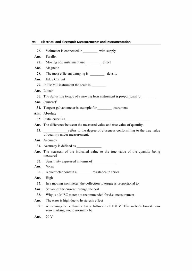
94 Electrical and Electronic Measurements and Instrumentation 26. Voltmeter is connected in ________ with supply
Ans. Parallel
27. Moving coil instrument use ________ effect
Ans. Magnetic
28. The most efficient damping is ________ density
Ans. Eddy Current
29. In PMMC instrument the scale is ________
Ans. Linear
30. The deflecting torque of a moving Iron instrument is proportional to ________
Ans. (current)2
31. Tangent galvanometer is example for ________ instrument
Ans. Absolute
32. Static error is a________________________________________________
Ans. The difference between the measured value and true value of quantity.
33. ______________refers to the degree of closeness conformiting to the true value of quantity under measurement.
Ans. Accuracy
34. Accuracy is defined as ______________
Ans. The nearness of the indicated value to the true value of the quantity being measured
35. Sensitivity expressed in terms of _____________
Ans. V/cm
36. A voltmeter contain a ________ resistance in series.
Ans. High
37. In a moving iron meter, the deflection to torque is proportional to
Ans. Square of the current through the coil
38. Why is a MISC meter not recommended for d.c. measurement
Ans. The error is high due to hysteresis effect
39. A moving-iron voltmeter has a full-scale of 100 V. This meter’s lowest non-zero marking would normally be
Ans. 20 V
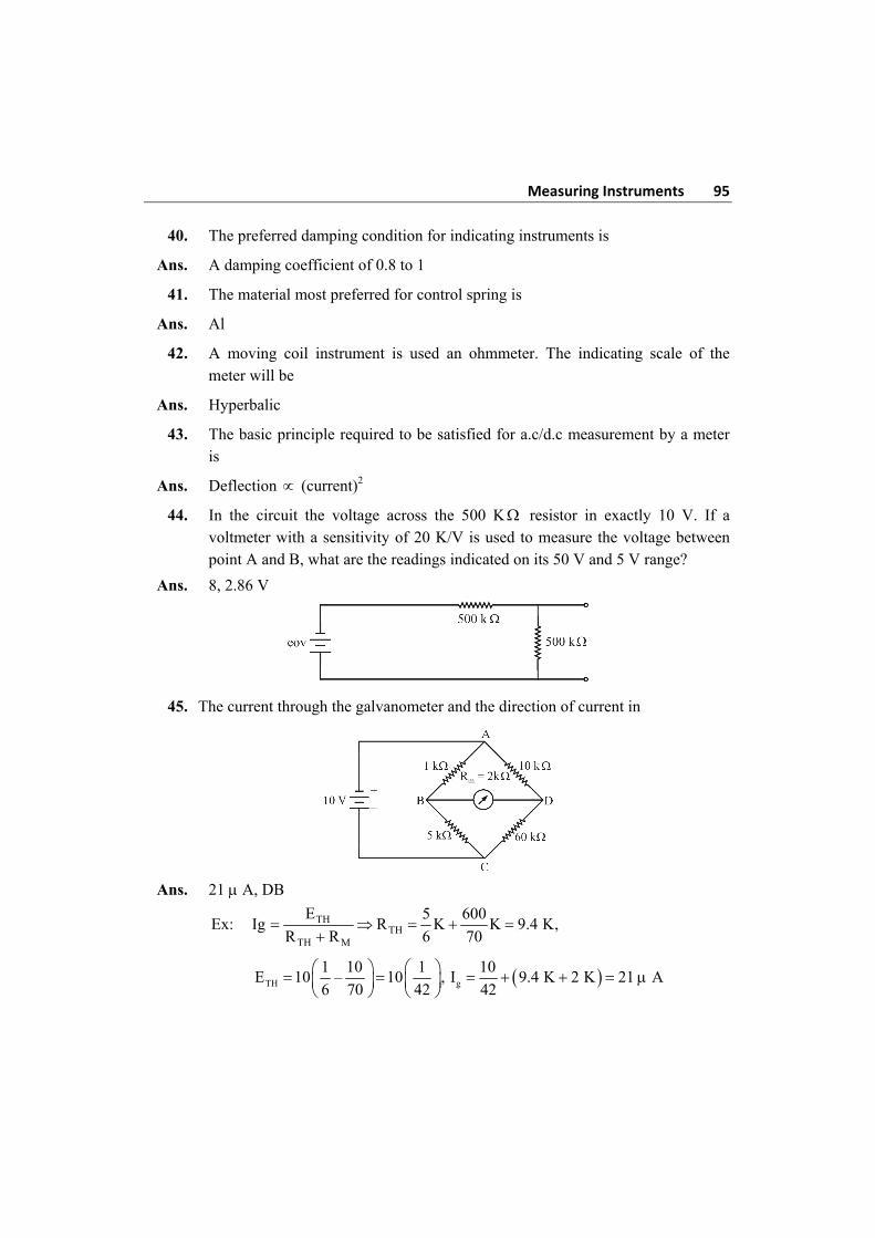
Measuring Instruments 95
40. The preferred damping condition for indicating instruments is
Ans. A damping coefficient of 0.8 to 1
41. The material most preferred for control spring is
Ans. Al
42. A moving coil instrument is used an ohmmeter. The indicating scale of the meter will be
Ans. Hyperbalic
43. The basic principle required to be satisfied for a.c/d.c measurement by a meter is
Ans. Deflection (current)2
44. In the circuit the voltage across the 500 K resistor in exactly 10 V. If a voltmeter with a sensitivity of 20 K/V is used to measure the voltage between point A and B, what are the readings indicated on its 50 V and 5 V range?
Ans. 8, 2.86 V
45. The current through the galvanometer and the direction of current in
Ans. 21 A, DB
Ex: Ig TH
THTH M
E 5 600R K K 9.4 K,
R R 6 70
TH
1 10 1E 10 – 10 ,
6 70 42
g
10I 9.4 K 2 K 21 A
42
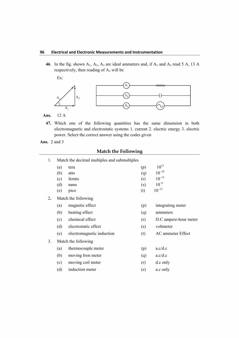
96 Electrical and Electronic Measurements and Instrumentation 46. In the fig. shown A1, A2, A3 are ideal ammeters and, if A1 and A3 read 5 A, 13 A
respectively, then reading of A2 will be
Ex:
Ans. 12 A
47. Which one of the following quantities has the same dimension in both electromagnetic and electrostatic systems 1. current 2. electric energy 3. electric power. Select the correct answer using the codes given
Ans. 2 and 3
Match the Following
1. Match the decimal multiples and submultiples
(a) tera (p) 1012
(b) atto (q) 10–18
(c) fernto (r) 10–15
(d) nano (s) 10–9
(e) pico (t) 10–12
2. Match the following
(a) magnetic effect (p) integrating meter
(b) heating effect (q) ammeters
(c) chemical effect (r) D.C ampere-hour meter
(d) electrostatic effect (s) voltmeter
(e) electromagnetic induction (t) AC ammeter Effect
3. Match the following
(a) thermocouple meter (p) a.c/d.c
(b) moving Iron meter (q) a.c/d.c
(c) moving coil meter (r) d.c only
(d) induction meter (s) a.c only
Measuring Instruments 97
4. Match List-I with List-II and select correct answer
List-I List-II (Instrument) (Example)
(a) indicating (p) energy meter
(b) analog (q) tangent galvanometer
(c) integrating (r) ammeter
(d) absolute (s) moving pointer
5. Match the following
(a) moving coil instrument (p) 2Td I (b) moving iron instrument (q) Td sin (c) spring control (r) moving coil (d) gravity control (s) moving iron (e) air friction damping (t) dT I
(u) cT 6. Match the following current and its effects
(a) ampere (p) light bulb
(b) milli ampere (q) mild shock
(c) kilo ampere (r) welding
(d) micro ampere (s) sensitive meters
(e) pico ampere (t) sensitive galvanometer
7. Specification of voltage to be measured Type of instruments suitable (a) 0 – 10 mV from a source of (p) PMMC internal resistance of 1 m Ω (b) thermo e.m.f ranging up to 5 mV (q) electronic from a thermo couple (c) supply voltage of 230 V 50 Hz (r) moving iron (d) r.m.s values of a voltage containing (s) thermal d.c and ripples at 50 Hz and harmonics
Quiz Questions Key
1. (b) 2. (c) 3. (c) 4. (d) 5. (b)
6. (b) 7. (d) 8. (b) 9. (a) 10. (a)
11. (a) 12. (d) 13. (a) 14. (a) 15. (b)
16. (c) 17. (d) 18. (b) 19. (c) 20. (b)
21. (a) 22. (b) 23. (b) 24. (c) 25. (c)
98 Electrical and Electronic Measurements and Instrumentation 26. (d) 27. (c) 28. (a) 29. (a) 30. (c)
31. (a) 32. (b) 33. (a) 34. (a) 35. (a)
36. (b) 37. (c) 38. (c) 39. (a)
Match the Following Key
1. a-s, b-p, c-t, d-r, e-q 2. a-s, b-p, c-t, d-q, e-r
3. a-p, b-q, c-r, d-s 4. a-r, b-s, c-p, d-q
5. a-t, b-p, c-u, d-q, e-s 6. a-r, b-p, c-t, d-q, e-s
7. a-p, b-q, c-r, d-s