Measurements as a Tool to Monitor Magnet Production
22
Measurements as a Tool to Monitor Magnet Production Animesh Jain Brookhaven National Laboratory Upton, New York 11973-5000, USA US Particle Accelerator School on Superconducting Accelerator Magnets Phoenix, Arizona, January 16-20, 2006
Transcript of Measurements as a Tool to Monitor Magnet Production
Measurements as a Toolto Monitor
Magnet Production
Animesh JainBrookhaven National Laboratory
Upton, New York 11973-5000, USA
US Particle Accelerator School on Superconducting Accelerator Magnets
Phoenix, Arizona, January 16-20, 2006
USPAS, Phoenix, January 16-20, 2006 Animesh Jain, BNL1
Introduction• The primary goal of magnetic measurements is to
provide the data necessary for smooth operation of accelerators, or for accurate analysis of data from detectors. (Need based measurements)
• Field quality is very sensitive to small changes in conductor placement and material properties. This makes magnetic measurements an excellent tool to monitor magnet production.
• Warm measurements, carried out in the early stages of production, can be particularly beneficial in providing a timely feedback.

USPAS, Phoenix, January 16-20, 2006 Animesh Jain, BNL2
Examples• Nearly all large scale magnet productions have
several instances where magnetic measurements have indicated a problem with the production.
• The problems could vary over a wide range, e.g.– Parts that are slightly out of tolerance– Material with undesirable magnetic properties– Incorrect or missing parts– Electrical shorts
• With a timely feedback, one can prevent use of defective magnets in complex assemblies, or minimize affected magnets in a large production.
USPAS, Phoenix, January 16-20, 2006 Animesh Jain, BNL3
Role of Data Analysis• Some problems cause a drastic change in field
quality, and are hard to miss.
• Some problems may be more subtle (e.g. a slow trend in the dimension of parts) and may require attention to detail.
• Some localized problems in a long magnet, even if drastic, may not show up in the integral field quality. Local variations must be studied.
• In all cases, once a problem is confirmed, it is important to provide useful clues as to what may possibly be wrong. This is not always easy.

USPAS, Phoenix, January 16-20, 2006 Animesh Jain, BNL4
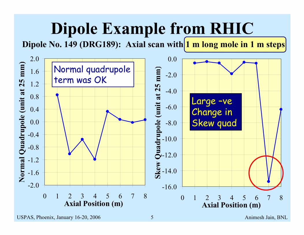
Dipole Example from RHICDipole No. 149 (DRG189): Axial scan with 1 m long mole in 1 m steps
0.7028
0.703
0.7032
0.7034
0.7036
0.7038
0.704
0.7042
0.7044
0 1 2 3 4 5 6 7 8Axial Position (m)
Tra
nsfe
r F
unct
ion
(T/k
A)
Warm meas. at the vendor’s site showed an unusual drop in transfer function (0.18%) at one location.
USPAS, Phoenix, January 16-20, 2006 Animesh Jain, BNL5
Dipole No. 149 (DRG189): Axial scan with 1 m long mole in 1 m steps
-2.0
-1.6
-1.2
-0.8
-0.4
0.0
0.4
0.8
1.2
1.6
2.0
0 1 2 3 4 5 6 7 8Axial Position (m)
Nor
mal
Qua
drup
ole
(uni
t at
25
mm
)
-16.0
-14.0
-12.0
-10.0
-8.0
-6.0
-4.0
-2.0
0.0
0 1 2 3 4 5 6 7 8Axial Position (m)
Skew
Qua
drup
ole
(uni
t at
25
mm
)
Dipole Example from RHIC
Normal quadrupole term was OK
Large –veChange in Skew quad

USPAS, Phoenix, January 16-20, 2006 Animesh Jain, BNL6
-5.0
-4.0
-3.0
-2.0
-1.0
0.0
1.0
2.0
3.0
0 1 2 3 4 5 6 7 8Axial Position (m)
Nor
mal
Sex
tupo
le (
unit
at
25 m
m)
-1.0
-0.8
-0.6
-0.4
-0.2
0.0
0.2
0.4
0.6
0.8
1.0
0 1 2 3 4 5 6 7 8Axial Position (m)
Skew
Sex
tupo
le (
unit
at
25 m
m)
Dipole No. 149 (DRG189): Axial scan with 1 m long mole in 1 m steps
Dipole Example from RHIC
Skew Sextupoleterm was OK
Large –vechange in Normal Sextupole
USPAS, Phoenix, January 16-20, 2006 Animesh Jain, BNL7
-0.4-0.20.00.20.40.60.81.01.21.41.61.82.02.2
0 1 2 3 4 5 6 7 8Axial Position (m)
Skew
Oct
upol
e (u
nit
at 2
5 m
m)
0.9
1.0
1.1
1.2
1.3
1.4
1.5
1.6
1.7
1.8
1.9
2.0
0 1 2 3 4 5 6 7 8Axial Position (m)
Nor
mal
Dec
apol
e (u
nit
at 2
5 m
m)
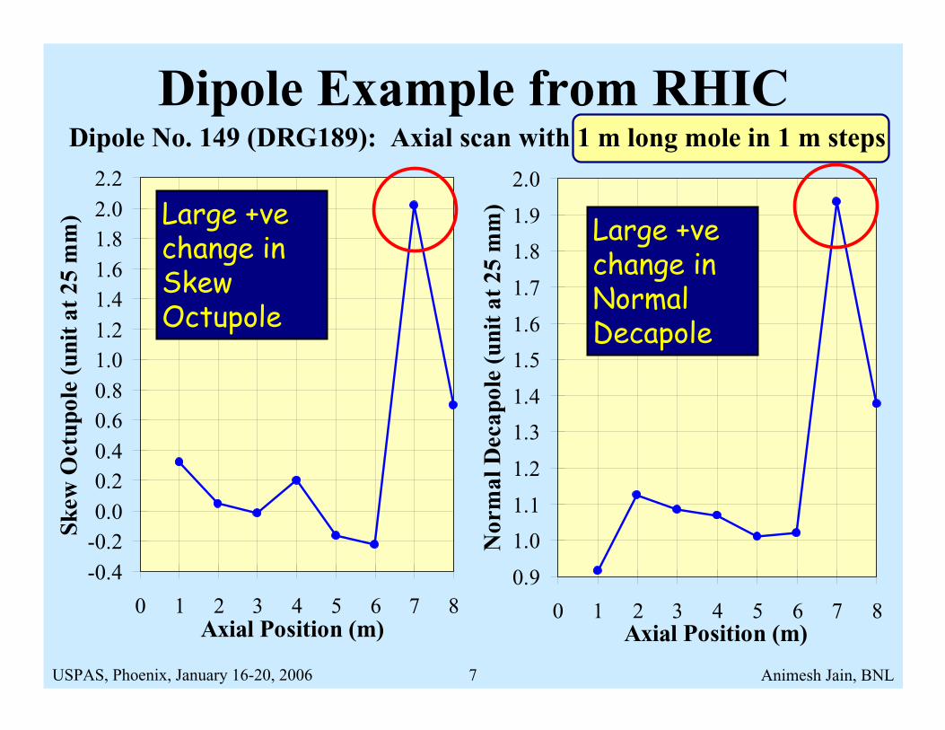
Dipole No. 149 (DRG189): Axial scan with 1 m long mole in 1 m steps
Dipole Example from RHIC
Large +vechange in Normal Decapole
Large +vechange in Skew Octupole
USPAS, Phoenix, January 16-20, 2006 Animesh Jain, BNL8
Dipole Example from RHIC• The unusual changes in transfer function, and
several harmonics, indicated a definite problem with the construction of the magnet.
• Only even skew and odd normal harmonics were affected. Even normal and odd skew terms were unaffected.
• Left-right anti-symmetry was preserved, buttop-bottom symmetry was not preserved.
• Changes in the signs of harmonics indicated that the problem is closer to the pole, than midplane.
USPAS, Phoenix, January 16-20, 2006 Animesh Jain, BNL9
0.7024
0.7026
0.7028
0.7030
0.7032
0.7034
0.7036
0.7038
0.7040
0.7042
6 6.5 7 7.5 8 8.5Axial Position (m)
Tra
nsfe
r F
unct
ion
(T/k
A)
-24.0-22.0-20.0-18.0-16.0-14.0-12.0-10.0-8.0-6.0-4.0-2.00.02.0
6 6.5 7 7.5 8 8.5Axial Position (m)
Skew
Qua
drup
ole
(uni
t at
25
mm
)
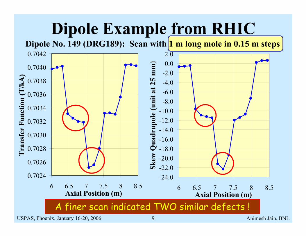
Dipole No. 149 (DRG189): Scan with 1 m long mole in 0.15 m stepsDipole Example from RHIC
A finer scan indicated TWO similar defects !

USPAS, Phoenix, January 16-20, 2006 Animesh Jain, BNL10
-8
-7
-6
-5
-4
-3
-2
-1
0
1
2
6 6.5 7 7.5 8 8.5Axial Position (m)
Nor
mal
Sex
tupo
le (
unit
at
25 m
m)
-0.5
0.0
0.5
1.0
1.5
2.0
2.5
3.0
6 6.5 7 7.5 8 8.5Axial Position (m)
Skew
Oct
upol
e (u
nit
at 2
5 m
m)
Dipole No. 149 (DRG189): Scan with 1 m long mole in 0.15 m stepsDipole Example from RHIC
Only one of the defects covered by the mole
BOTH defects covered by the mole
USPAS, Phoenix, January 16-20, 2006 Animesh Jain, BNL11
Dipole Example: Summary• The nature of harmonics indicated that the coil
turns near the upper pole have moved symmetrically towards the vertical axis.
• There were two defect regions, each about 0.15m long.
• RHIC dipoles use 0.15 m long RX630 pole spacers between coil and yoke. The end section spacers are different from the straight section.
• The end type of spacers were inadvertently used in the straight section. This was verified later.

USPAS, Phoenix, January 16-20, 2006 Animesh Jain, BNL12
Shorts in a Multilayer Magnet• BNL has recently built several multilayer
magnets for the HERA upgrade program at DESY, Hamburg.
• These magnets were fabricated by winding a 1 mm diameter superconducting cable using an automatic winding machine.
• The magnets had several layers of coils with different multipolarities.
• On two occasions, the coil curing process produced electrical shorts.

USPAS, Phoenix, January 16-20, 2006 Animesh Jain, BNL13
Splice Between “Sub-coils”
Splice
Pole Lead
Pole Lead
USPAS, Phoenix, January 16-20, 2006 Animesh Jain, BNL14
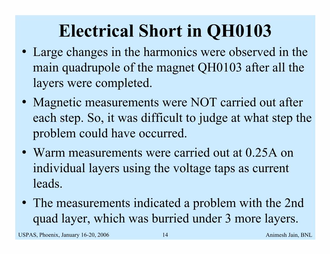
Electrical Short in QH0103• Large changes in the harmonics were observed in the
main quadrupole of the magnet QH0103 after all the layers were completed.
• Magnetic measurements were NOT carried out after each step. So, it was difficult to judge at what step the problem could have occurred.
• Warm measurements were carried out at 0.25A on individual layers using the voltage taps as current leads.
• The measurements indicated a problem with the 2nd quad layer, which was burried under 3 more layers.
USPAS, Phoenix, January 16-20, 2006 Animesh Jain, BNL15
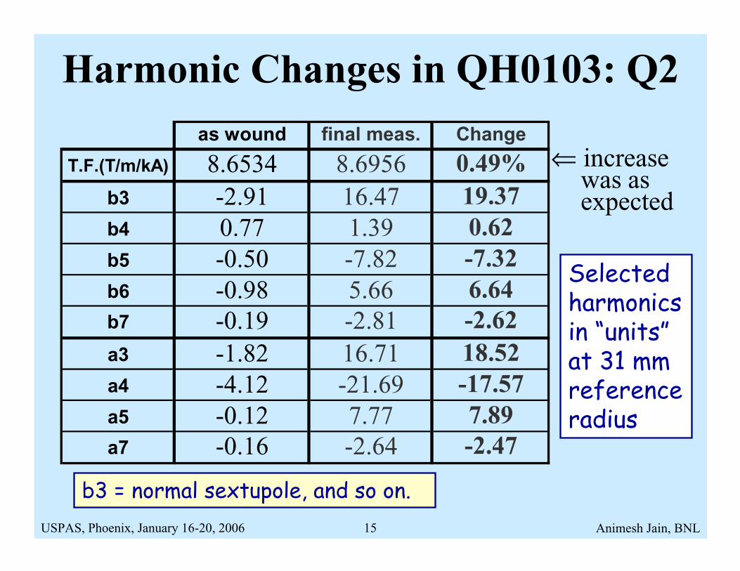
Harmonic Changes in QH0103: Q2as wound final meas. Change
T.F.(T/m/kA) 8.6534 8.6956 0.49%b3 -2.91 16.47 19.37b4 0.77 1.39 0.62b5 -0.50 -7.82 -7.32b6 -0.98 5.66 6.64b7 -0.19 -2.81 -2.62a3 -1.82 16.71 18.52a4 -4.12 -21.69 -17.57a5 -0.12 7.77 7.89a7 -0.16 -2.64 -2.47
Selected harmonics in “units”at 31 mm reference radius
⇐ increase was asexpected
b3 = normal sextupole, and so on.
USPAS, Phoenix, January 16-20, 2006 Animesh Jain, BNL16
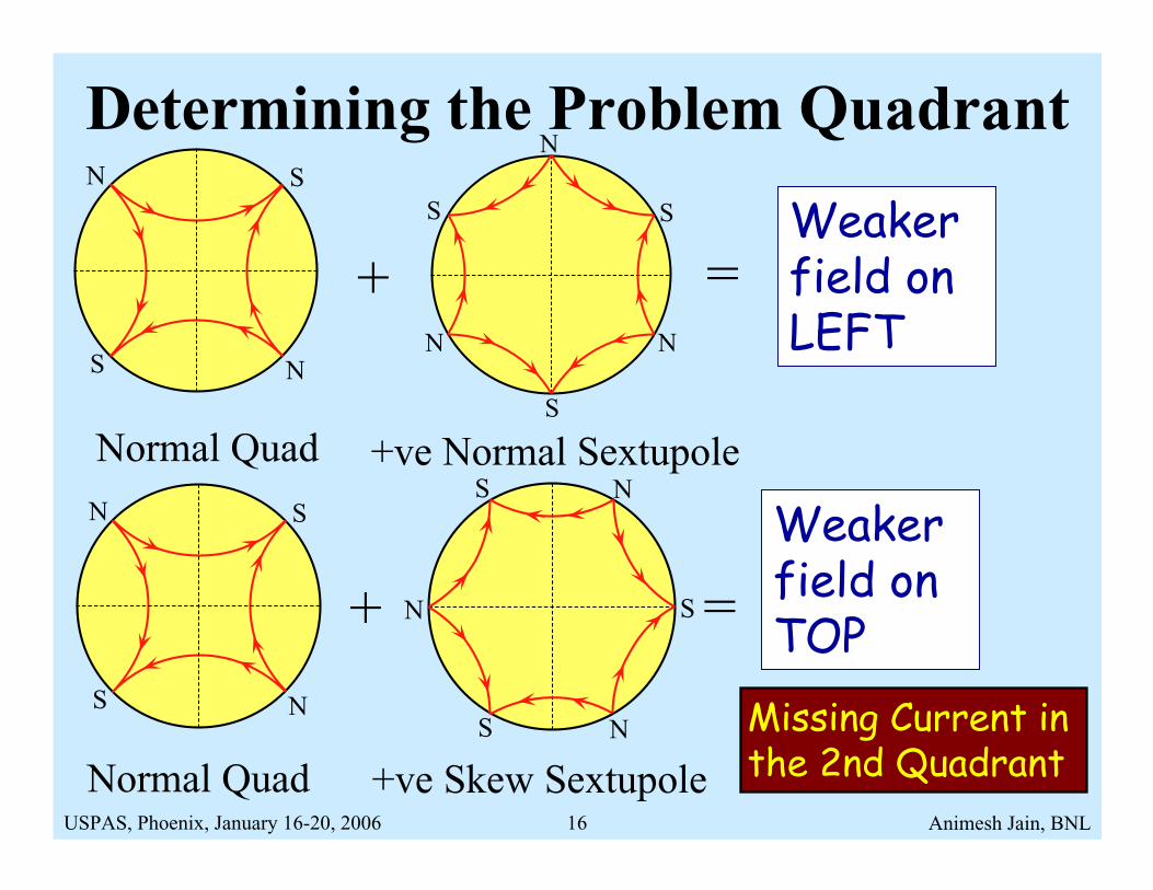
Determining the Problem Quadrant
+ =
Normal Quad +ve Normal Sextupole
+ =
Missing Current in the 2nd Quadrant
Weaker field on LEFT
S
S N
NS S
N
N N
S
Normal Quad
S
S N
N
+ve Skew Sextupole
S
S
N
N
NS
Weaker field on TOP

USPAS, Phoenix, January 16-20, 2006 Animesh Jain, BNL17
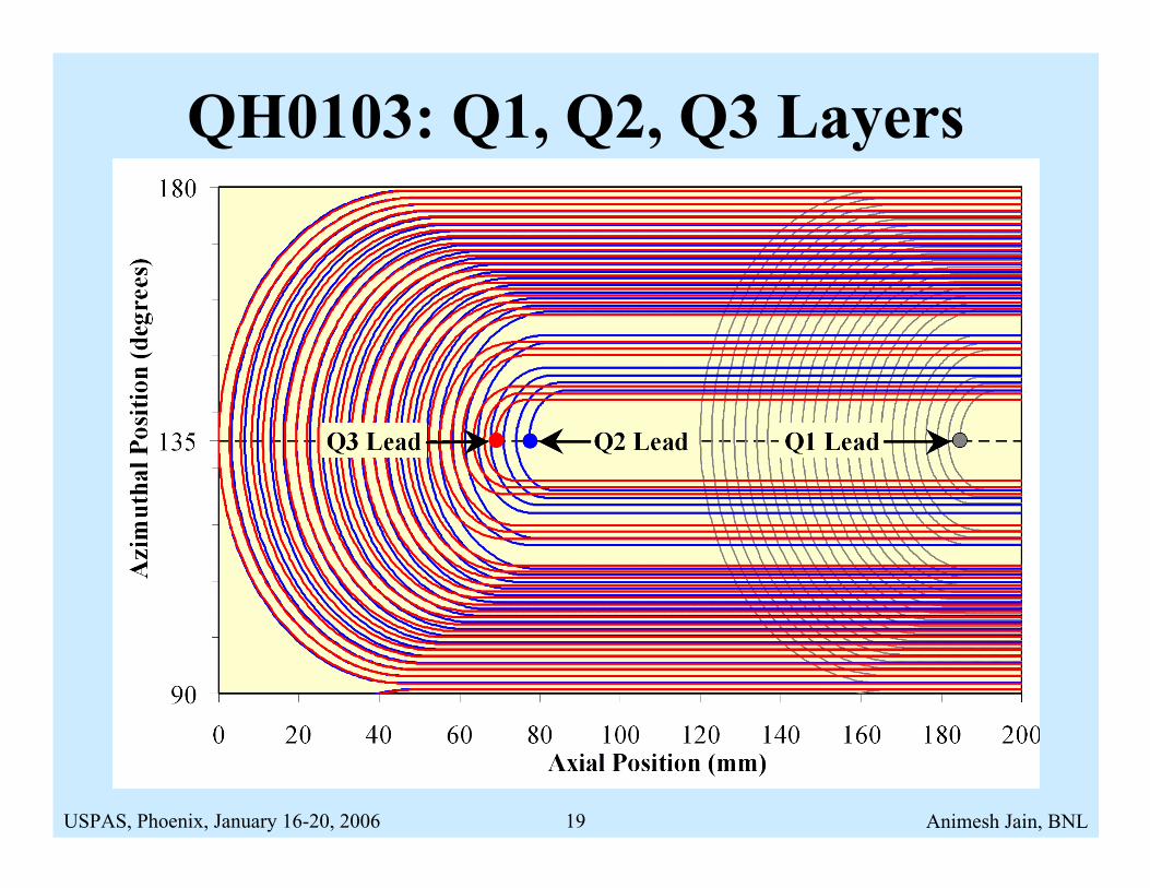
Modeling Field Errors in QH0103• Most likely area: pole lead in the 2nd quadrant.
• Would bypass current from the pole-most turn.
-6.5
0
6.5
-6.5 0 6.5X (cm)
Y (c
m)
Zero Current
QH0103: Q2

USPAS, Phoenix, January 16-20, 2006 Animesh Jain, BNL18
Computed Vs Measured Changes
-60
-50
-40
-30
-20
-10
0
10
20
30
40
50
60
2 3 4 5 6 7 8 9 10 11 12 13 14 15 16Harmonic Number
Cha
nge
in H
arm
onic
(un
its
at 5
0 m
m)
Normal: MeasuredNormal: CalculatedSkew: MeasuredSkew: Calculated
Note: Reference radius increased from 31 mm to 50 mm to clearly show the higher harmonics
USPAS, Phoenix, January 16-20, 2006 Animesh Jain, BNL19
QH0103: Q1, Q2, Q3 Layers
USPAS, Phoenix, January 16-20, 2006 Animesh Jain, BNL20
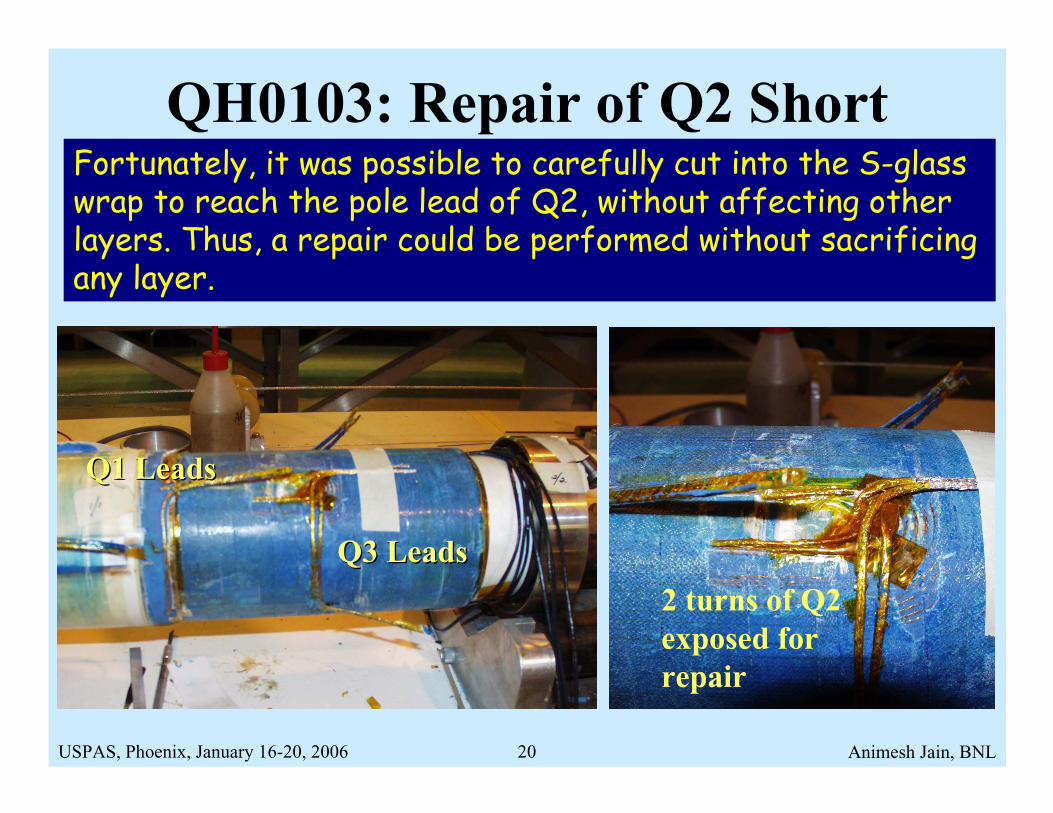
QH0103: Repair of Q2 ShortFortunately, it was possible to carefully cut into the S-glass wrap to reach the pole lead of Q2, without affecting other layers. Thus, a repair could be performed without sacrificing any layer.
2 turns of Q2 exposed for repair
Q3 LeadsQ3 Leads
Q1 LeadsQ1 Leads

USPAS, Phoenix, January 16-20, 2006 Animesh Jain, BNL21
Conclusions• Warm measurements have proved to be a very
sensitive tool to monitor magnet production.• Accurate harmonic information, coupled with
a model analysis, can provide exact location of defects. This may allow for efficient repairs in some cases.
• Gross errors are often easy to detect and model. Subtle changes may be hard to model.
• One must be careful in interpreting data from long probes. A “deconvolution” of data may be needed to better characterize the defects.