Measurement - BreakWater International · Housing with threaded ends Cast Brass Spheroidal graphite...
40
CONTOIL® Measurement
Transcript of Measurement - BreakWater International · Housing with threaded ends Cast Brass Spheroidal graphite...
CONTOIL®Measurement
2
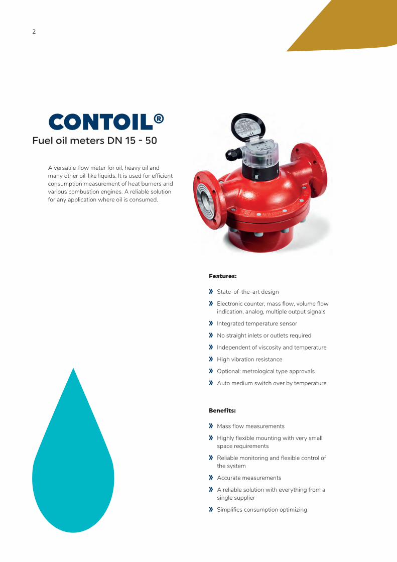
CONTOIL®Fuel oil meters DN 15 - 50
A versatile flow meter for oil, heavy oil and many other oil-like liquids. It is used for efficient consumption measurement of heat burners and various combustion engines. A reliable solution for any application where oil is consumed.
Features:
State-of-the-art design
Electronic counter, mass flow, volume flow indication, analog, multiple output signals
Integrated temperature sensor
No straight inlets or outlets required
Independent of viscosity and temperature
High vibration resistance
Optional: metrological type approvals
Auto medium switch over by temperature
Benefits:
Mass flow measurements
Highly flexible mounting with very small space requirements
Reliable monitoring and flexible control of the system
Accurate measurements
A reliable solution with everything from a single supplier
Simplifies consumption optimizing
3
CONTENTIntroduction 4
Operating principle 5
CONTOIL® flexibility 7
Product range 8
Technical specifications 10
Project planning notes 27
Installation 32
Warranty, safety instructions 37
Certificates 38
4
INTRODUCTIONThank you for your decision to work with Aquametro Oil & Marine Fuel Performance Products. This technical specification describes the installation, commissioning and use of CONTOIL® fuel oil meters. For additional information please contact your local sales agent at: www.aquametro-oil-marine.com.
Liability Disclaimer
The manufacturer cannot monitor the compliance to this manual as well as the conditions and methods during the installation, operation, usage and maintenance of the system regulator. Improper installation can cause damage and endanger people. Therefore, we assume no responsibility and liability for losses, damage or costs that result due to incorrect installation, improper operation, usage and maintenance or in any manner associated therewith. Similarly, we assume no responsibility for patent right or other right infringements of third parties caused by usage of this system regulator. The manufacturer reserves the right, without prior notification, to make modifications concerning the product, technical data or installation and operating manual.
Safety precautions
CONTOIL® fuel oil meters must only be used for their intended purpose and comply with local and international safety regulations. All documentation is to be followed exactly. None of the information stated here or elsewhere releases planners, installers and operators from their own careful and comprehensive assessment of the respective plant configuration in terms of functional capability and operational safety.
Local applicable working regulations must be complied with, during all work on the plant and / or ship. All safety, installation and operation instructions as described in this manual must be followed. Sensors are sensitive measuring instruments and should be treated carefully.
5
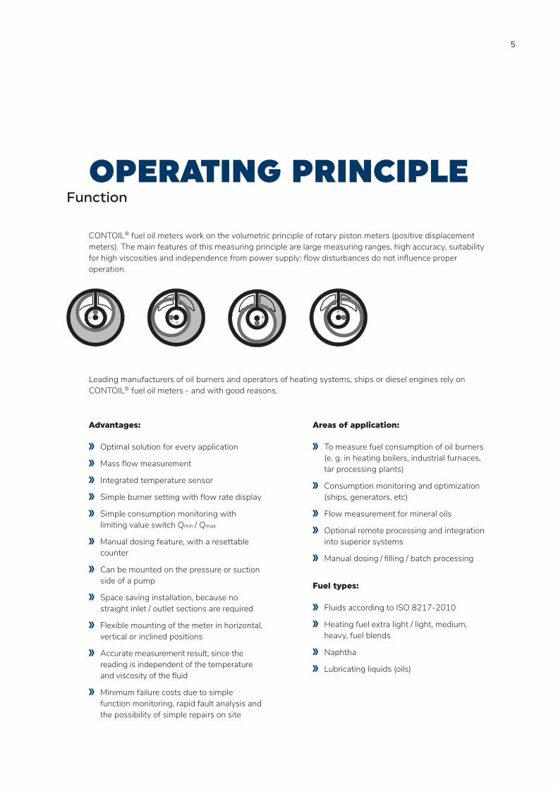
OPERATING PRINCIPLEFunction
CONTOIL® fuel oil meters work on the volumetric principle of rotary piston meters (positive displacement meters). The main features of this measuring principle are large measuring ranges, high accuracy, suitability for high viscosities and independence from power supply; flow disturbances do not influence proper operation.
Leading manufacturers of oil burners and operators of heating systems, ships or diesel engines rely on CONTOIL® fuel oil meters - and with good reasons.
Advantages:
Optimal solution for every application
Mass flow measurement
Integrated temperature sensor
Simple burner setting with flow rate display
Simple consumption monitoring with limiting value switch Qmin / Qmax
Manual dosing feature, with a resettable counter
Can be mounted on the pressure or suction side of a pump
Space saving installation, because no straight inlet / outlet sections are required
Flexible mounting of the meter in horizontal, vertical or inclined positions
Accurate measurement result, since the reading is independent of the temperature and viscosity of the fluid
Minimum failure costs due to simple function monitoring, rapid fault analysis and the possibility of simple repairs on site
Areas of application:
To measure fuel consumption of oil burners (e. g. in heating boilers, industrial furnaces, tar processing plants)
Consumption monitoring and optimization (ships, generators, etc)
Flow measurement for mineral oils
Optional remote processing and integration into superior systems
Manual dosing / filling / batch processing
Fuel types:
Fluids according to ISO 8217-2010
Heating fuel extra light / light, medium, heavy, fuel blends
Naphtha
Lubricating liquids (oils)

6
Type key
VZ A 25 FL 180 / 25 IN- 0.1
Pulse value0.1 0.1 l/p1 1 l/p10 10 l/p
Pulse typeRV ReedIN NAMUR
Nominal pressure16 max. 16 bar DIN25 max. 25 bar DIN40 max. 40 bar DIN5 K JIS10 - 20 K JIS150 ASME300 ASME
Temperature130 max. 130 °C 180 max. 180 °C
Connection typeRC threadFL flange
Nominal size15 15 mm, ½ "20 20 mm, ¾ "25 25 mm, 1 "40 40 mm, 1½ "50 50 mm, 2 "
Class_ max. standard error ±1 %A max. error ±0.5 %
Product SeriesVZO mechanical display unit (VZO 25 FL 180/RV0.1)VZF II electronic display unit (VZFA II 25 FL 180/25)
7
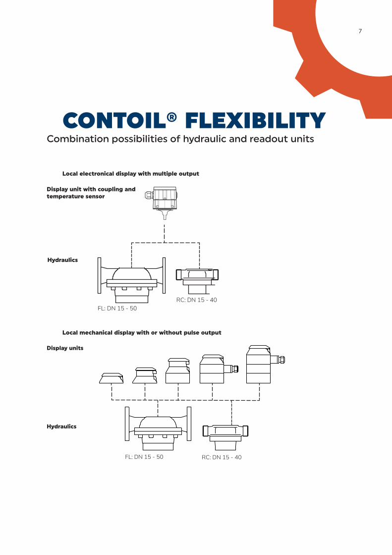
FL: DN 15 - 50RC: DN 15 - 40
Display unit with coupling and temperature sensor
Hydraulics
Local electronical display with multiple output
Display units
Hydraulics
FL: DN 15 - 50 RC: DN 15 - 40
Local mechanical display with or without pulse output
CONTOIL® FLEXIBILITYCombination possibilities of hydraulic and readout units
8
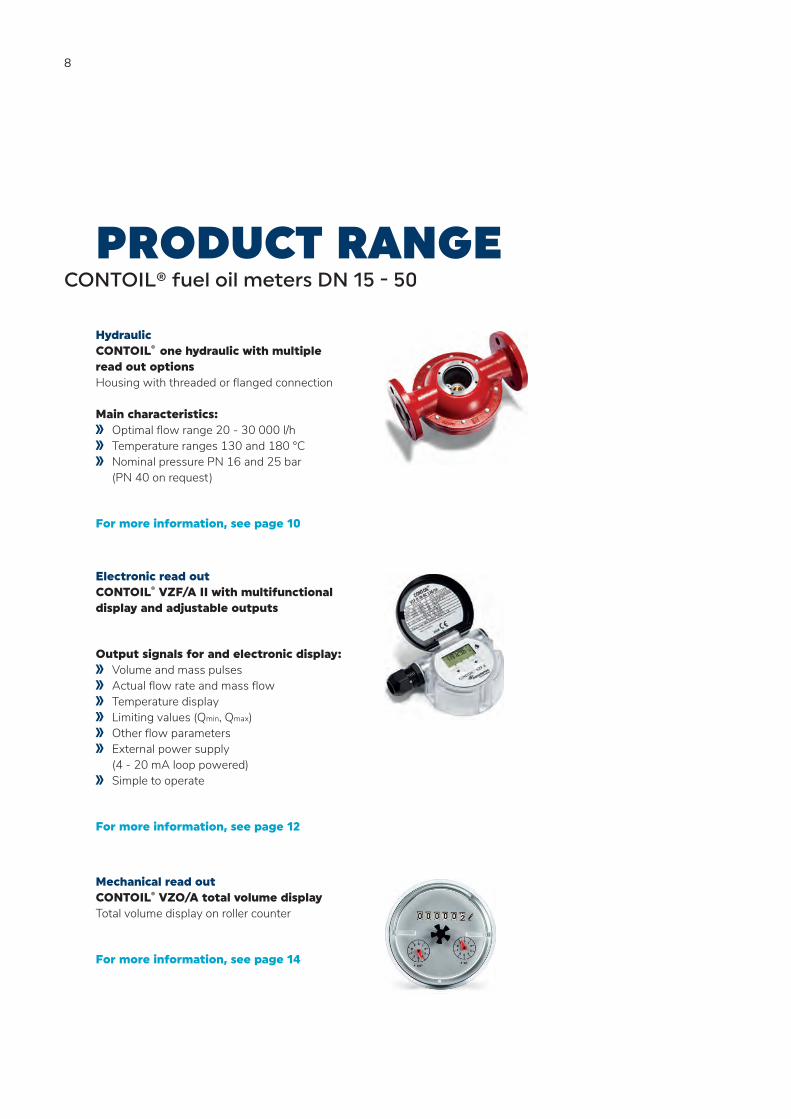
PRODUCT RANGECONTOIL® fuel oil meters DN 15 - 50
Electronic read out CONTOIL® VZF/A II with multifunctional display and adjustable outputs
Output signals for and electronic display: Volume and mass pulses Actual flow rate and mass flow Temperature display Limiting values (Qmin, Qmax) Other flow parameters External power supply
(4 - 20 mA loop powered) Simple to operate
For more information, see page 12
Hydraulic CONTOIL® one hydraulic with multiple read out options Housing with threaded or flanged connection Main characteristics:
Optimal flow range 20 - 30 000 l/h Temperature ranges 130 and 180 °C Nominal pressure PN 16 and 25 bar
(PN 40 on request)
For more information, see page 10
Mechanical read out CONTOIL® VZO/A total volume display Total volume display on roller counter
For more information, see page 14

9
Mechanical read out with pulse CONTOIL® VZO/A RV/IN total volume display and remote transmission
Total volume display on roller counter with Reed pulse RV for remote totalization Inductive IN pulse for control purposes
For more information, see page 14
Blind with pulse CONTOIL® DFM compact design for remote display transmission Pulse value for remote totalizing
For more information, see page 16
CONTOIL® CE MID 2014/32/EU for verified applications where an approved measurement system is required Conformity approved read out
For more information, see page 18
10
Hydraulic Meter DN size
Nominal diameter DN mm 15 20 25 40 50
inch 1/2 3/4 1 1 1/2 2
Installation length mm 165 165 190 300 350
Nominal pressure threaded ends PN bar 16 16 16 16 N/A
Nominal pressure flanges PN bar 25 / 40 25 / 40 25 / 40 25 / 40 25 / 40
Maximum flow rate Qmax1) l/h 600 1500 3000 9000 30000Continuous flow rate Qcont2) l/h 400 1000 2000 6000 20000
Minimum flow rate Qmin l/h 20 40 75 225 750
Approx. starting flow rate l/h 4 12 30 90 300
Max. permissible error of acutal value¹) VZF II, VZO, DFM <±1.0 % <±1.0 % <±1.0 % <±1.0 % <±1.0 %
VZFA II, VZOA <±0.5 % <±0.5 % <±0.5 % <±0.5 % <±0.5 %
VZFA II linearized <±0.3 % <±0.3 % <±0.3 % <±0.3 % <±0.3 %
Repeatability <±0.1 % <±0.1 % <±0.1 % <±0.1 % <±0.1 %
Measuring chamber volume cm³ 12 36 100 330 1200
Safety filter mesh size mm 0.400 0.400 0.400 0.800 0.800
Weight with threaded ends3) kg 2.2 2.5 4.2 17.3 -
Weight with flanges PN 25 kg 3.8 4.5 7.5 20.3 41.0
Weight with flanges PN 40 kg 4.4 5.5 7.8 20.5 42.01) Manufacturer‘s specification, valid for the reference conditions as specified under Reference conditions.
2) For burners and engines or motors, the fuel oil meter must be selected on the basis of the permanent flow rate. For higher viscosities, or if the meter is installed on the suction side, the pressure drop and any reduction in the measuring range must be taken into consideration.
3) Weight without couplings.
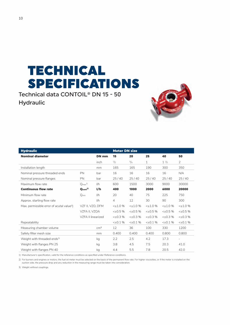
TECHNICAL SPECIFICATIONS
Technical data CONTOIL® DN 15 - 50 Hydraulic
11
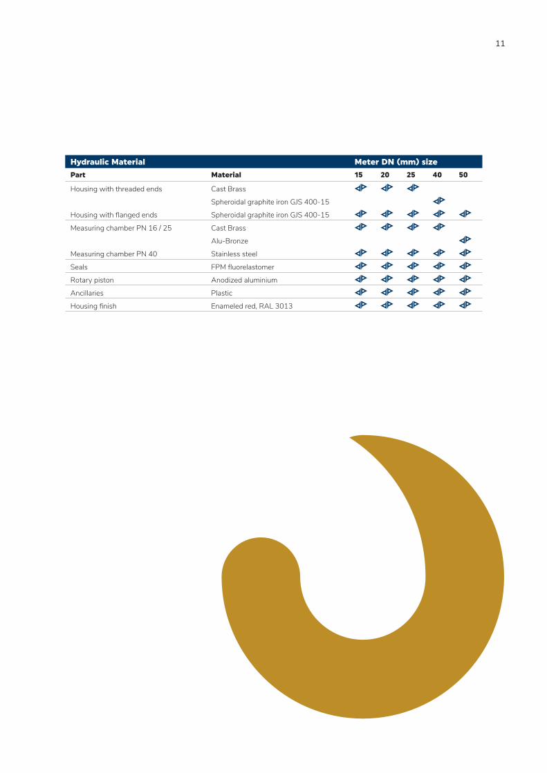
Hydraulic Material Meter DN (mm) size
Part Material 15 20 25 40 50
Housing with threaded ends Cast Brass
Spheroidal graphite iron GJS 400-15
Housing with flanged ends Spheroidal graphite iron GJS 400-15
Measuring chamber PN 16 / 25 Cast Brass
Alu-Bronze
Measuring chamber PN 40 Stainless steel
Seals FPM fluorelastomer
Rotary piston Anodized aluminium
Ancillaries Plastic
Housing finish Enameled red, RAL 3013
12
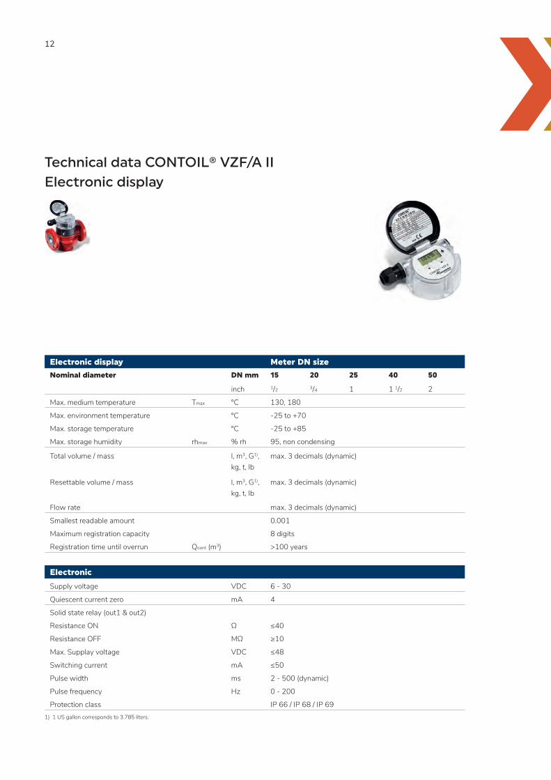
Electronic display Meter DN size
Nominal diameter DN mm 15 20 25 40 50
inch 1/2 3/4 1 1 1/2 2
Max. medium temperature Tmax °C 130, 180
Max. environment temperature °C -25 to +70
Max. storage temperature °C -25 to +85
Max. storage humidity rhmax % rh 95, non condensing
Total volume / mass l, m3, G1), kg, t, lb
max. 3 decimals (dynamic)
Resettable volume / mass l, m3, G1), kg, t, lb
max. 3 decimals (dynamic)
Flow rate max. 3 decimals (dynamic)
Smallest readable amount 0.001
Maximum registration capacity 8 digits
Registration time until overrun Qcont (m3) >100 years
Electronic
Supply voltage VDC 6 - 30
Quiescent current zero mA 4
Solid state relay (out1 & out2)
Resistance ON Ω ≤40
Resistance OFF MΩ ≥10
Max. Supplay voltage VDC ≤48
Switching current mA ≤50
Pulse width ms 2 - 500 (dynamic)
Pulse frequency Hz 0 - 200
Protection class IP 66 / IP 68 / IP 691) 1 US gallon corresponds to 3.785 liters.
Technical data CONTOIL® VZF/A II Electronic display
13
Outputs
3 (2 pulse / frequency, 1 analog 4 - 20 mA) freely selectable, totally independent of each other
Pulse value totalizer volume or mass pulse 0 - 200 pulse/sec. (50 % duty cycle)
Current 4 - 20 mA volume flow, mass flow or temperature signal
Frequency Qmin, Qmax volume flow, mass flow or temperatur minimum, maximum and hysteresis parameterized
Limit switch QLimmax, QLimmin allows you to set an alert whenever predefined flow rates are exceeded (NC / NO)
State switch Alarm, Error state and on/off parameterized (NC / NO)
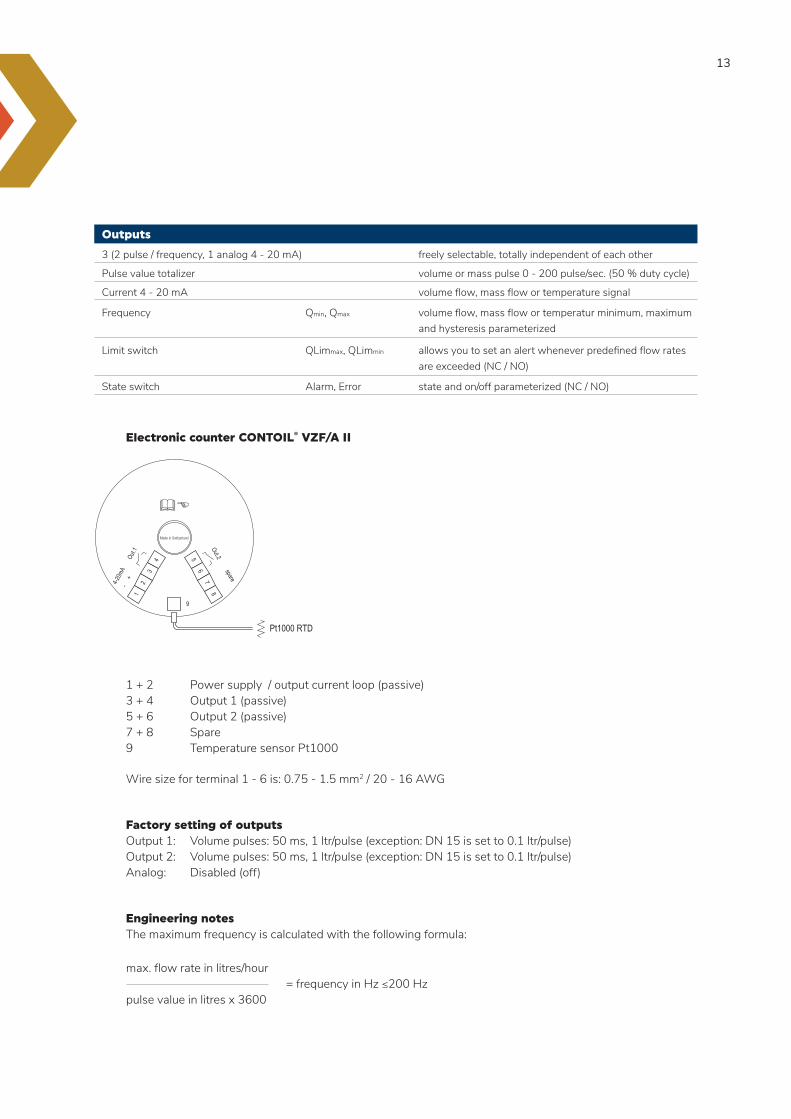
Electronic counter CONTOIL® VZF/A II
1 + 2 Power supply / output current loop (passive) 3 + 4 Output 1 (passive) 5 + 6 Output 2 (passive) 7 + 8 Spare 9 Temperature sensor Pt1000
Wire size for terminal 1 - 6 is: 0.75 - 1.5 mm2 / 20 - 16 AWG
Factory setting of outputs Output 1: Volume pulses: 50 ms, 1 ltr/pulse (exception: DN 15 is set to 0.1 ltr/pulse) Output 2: Volume pulses: 50 ms, 1 ltr/pulse (exception: DN 15 is set to 0.1 ltr/pulse) Analog: Disabled (off)
Engineering notes The maximum frequency is calculated with the following formula:
12
34 5
67
8Out.2Ou
t.1
4-20m
A spare
- +
9
Pt1000 RTD
max. flow rate in litres/hour = frequency in Hz ≤200 Hz pulse value in litres x 3600
14
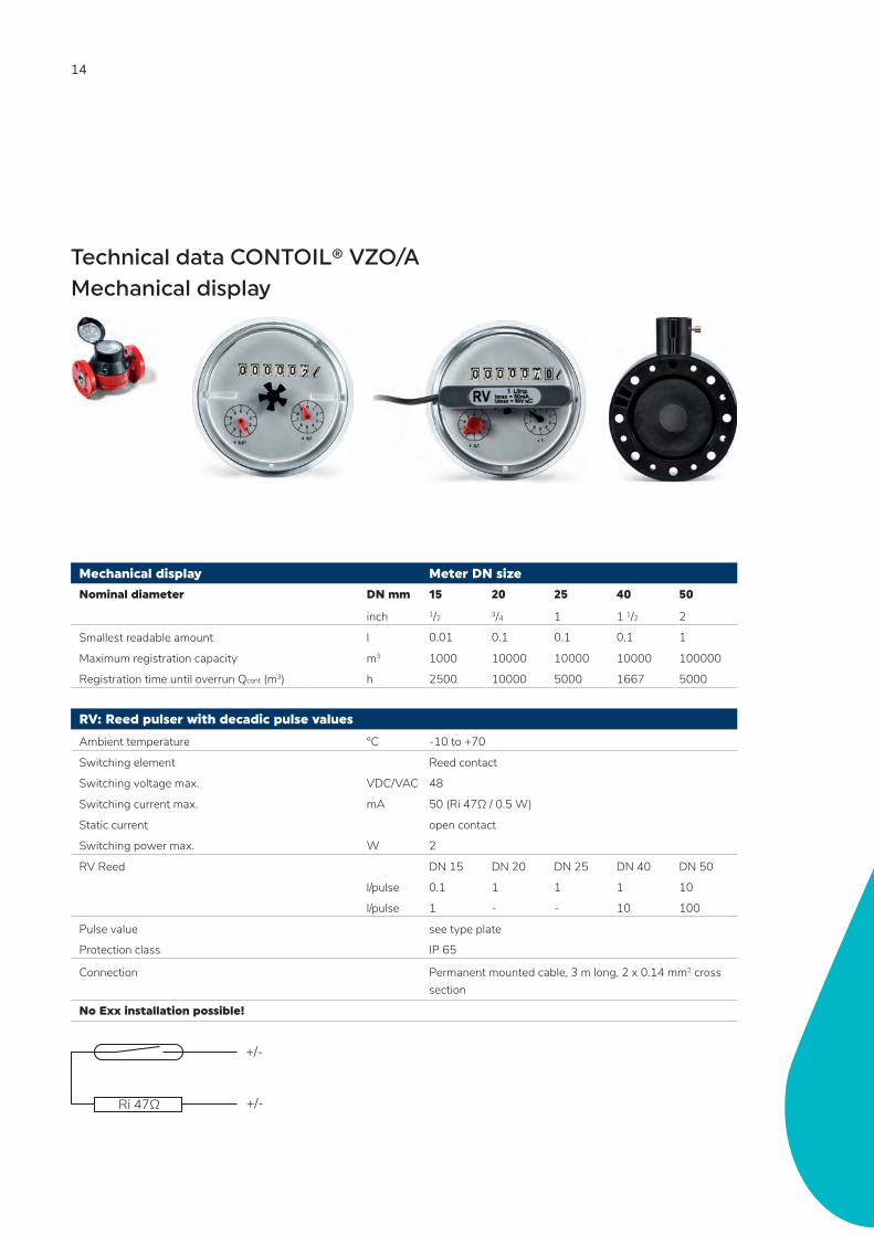
Mechanical display Meter DN size
Nominal diameter DN mm 15 20 25 40 50
inch 1/2 3/4 1 1 1/2 2
Smallest readable amount l 0.01 0.1 0.1 0.1 1
Maximum registration capacity m3 1000 10000 10000 10000 100000
Registration time until overrun Qcont (m3) h 2500 10000 5000 1667 5000
RV: Reed pulser with decadic pulse values
Ambient temperature °C -10 to +70
Switching element Reed contact
Switching voltage max. VDC/VAC 48
Switching current max. mA 50 (Ri 47Ω / 0.5 W)
Static current open contact
Switching power max. W 2
RV Reed DN 15 DN 20 DN 25 DN 40 DN 50
l/pulse 0.1 1 1 1 10
l/pulse 1 - - 10 100
Pulse value see type plate
Protection class IP 65
Connection Permanent mounted cable, 3 m long, 2 x 0.14 mm2 cross section
No Exx installation possible!
Technical data CONTOIL® VZO/A Mechanical display
+/-
+/-Ri 47Ω

15
IN: Inductive pulser with decadic pulse values
Supply voltage VDC 5 - 25
Ambient temperature °C -10 to +70
Switching element Slot initiator acc. to IEC 60947-5-6 (IN - NAMUR)
Operating voltage max. VDC 8.2
Residual ripple <5 %
Switching current mA >3 (at 8.2 V, 1 kΩ)
Static current zero mA >1 (at 8.2 V, 1 kΩ)
Pulse values for remote transmitter IN (NAMUR) inductive (IEC 60947-5-6)
l/pulse
DN 15 0.01
DN 200.01
DN 25 0.1
DN 40 0.1
DN 50 1
Pulse value see type plate
Protection class IP 65
Connection Connection cable min. 2 x 0.35 mm2 and 5.5 - 13 mm external cable diameter on plug (Prefabricated cable available)
Pay attention to polarity when connecting the plug!

16
DFM blind unit Meter DN size
Nominal diameter DN mm 20 25
inch 3/4 1
Electronic
Supply voltage VDC 6 - 32
Operating temperature °C -20 to +80
Storage temperature °C -40 to +125
Switching element open drain
Supply voltage VDC 12/24 board systems
Switching voltage VDC/VAC 48
Switching current max. mA 50
Pulse value see type plate
Pulse width ms 20
Protection class IP 66
Technical data CONTOIL® DFM blind

17
Options for CONTOIL®
Pairing
If the application consists of a differential measurement (supply and return), the CONTOIL® VZFA II or VZOA can be paired with higher accuracy. The flow is measured in the supply and return line pipes. The difference between the two measurements is regarded as the consumption. To obtain optimal measurement results, CONTOIL® VZFA II or VZOA fuel oil meters are calibrated in pairs, they are adapted precisely to the plant/system operating conditions. The flow rate occurring in each meter, the permissible pressure drop and the viscosity of the fluid must all be considered during the design phase.
The pairing range of the fuel oil meters is obtained as follows: Flow in supply section less maximum consumption = flow in return section.
When the order is placed, the following additional information is required: flow rate in supply section e. g. fixed pumping rate 200 l/h flow rate in return section e. g. 120 - 190 l/h (consumption of 10 - 80 l/h)
The meters are marked “supply” and “return” during calibration and final testing in the factory. They must then be installed in the designated location. For further information on the subject of differential measurement, see the section “Project planning notes”.
Linearization
The CONTOIL® VZFA II can be linearized to acheive an even better accuracy of ±0.3 % across the full measuring range (Qmin - Qmax). During this calibration process the flow meter is being tested across the full range with a maximunm of 15 measuring points and than linearized and tested.
Reference conditions
Measuring error limits according to technical data of meter in % of actual value for the whole measuring range. Calibration medium: Calibration oil is similar to extra light heating oil, density at 20 °C = 814 kg/m3 Viscosity = 5.0 mm2/s according to DIN 51757 / ISO 3104 (corresponds to 4.1 mPa.s) Temperature: 18 - 25 °C Horizontal mounting, readings from counter. CONTOIL® oil meters are never to be tested with water, otherwise they will get damaged.
Standard measuring curve
Qmin 10 20 40 5030 60 70 80 90 100 % Qmax
+1 %0
–1 %
Max
. per
mis
sabl
e er
ror
Flow rate
18
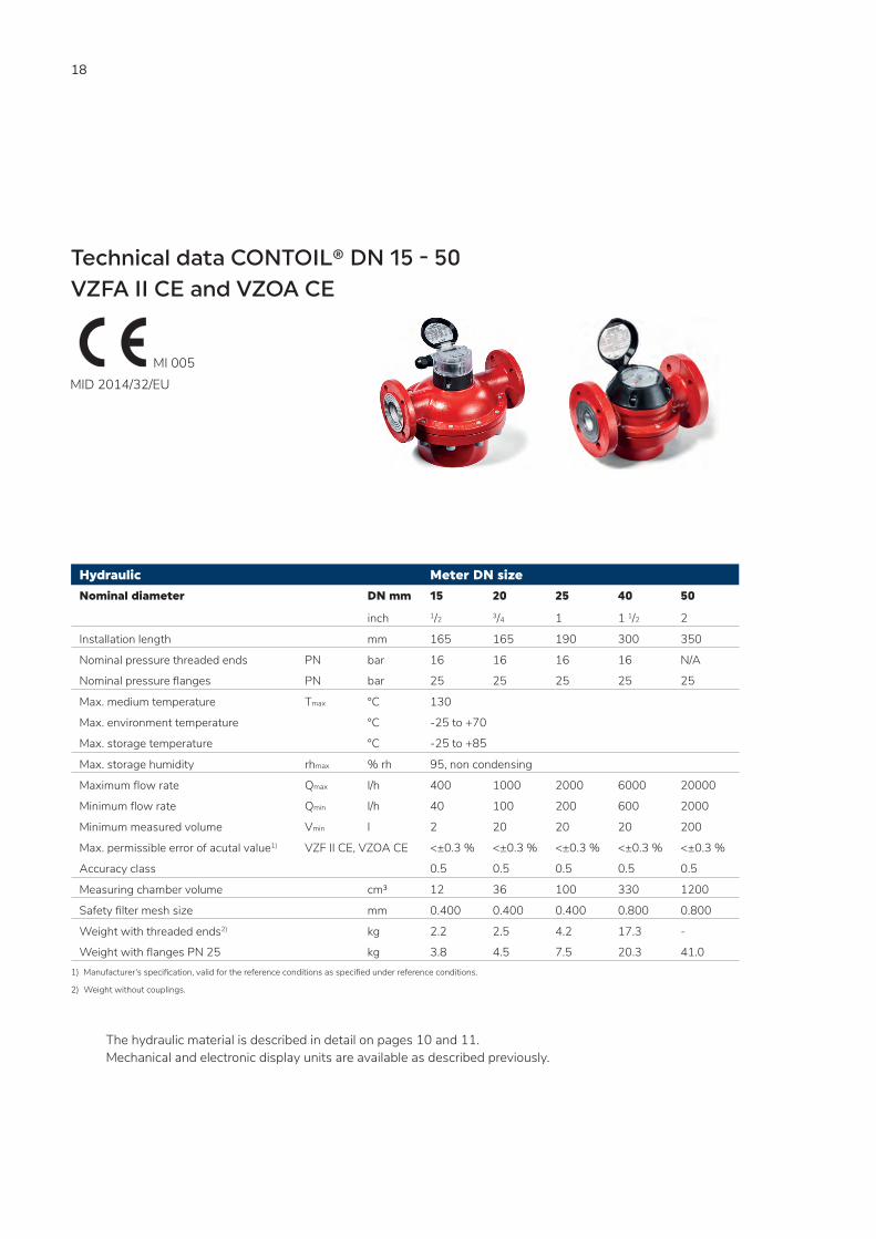
Hydraulic Meter DN size
Nominal diameter DN mm 15 20 25 40 50
inch 1/2 3/4 1 1 1/2 2
Installation length mm 165 165 190 300 350
Nominal pressure threaded ends PN bar 16 16 16 16 N/A
Nominal pressure flanges PN bar 25 25 25 25 25
Max. medium temperature Tmax °C 130
Max. environment temperature °C -25 to +70
Max. storage temperature °C -25 to +85
Max. storage humidity rhmax % rh 95, non condensing
Maximum flow rate Qmax l/h 400 1000 2000 6000 20000
Minimum flow rate Qmin l/h 40 100 200 600 2000
Minimum measured volume Vmin l 2 20 20 20 200
Max. permissible error of acutal value1) VZF II CE, VZOA CE <±0.3 % <±0.3 % <±0.3 % <±0.3 % <±0.3 %
Accuracy class 0.5 0.5 0.5 0.5 0.5
Measuring chamber volume cm³ 12 36 100 330 1200
Safety filter mesh size mm 0.400 0.400 0.400 0.800 0.800
Weight with threaded ends2) kg 2.2 2.5 4.2 17.3 -
Weight with flanges PN 25 kg 3.8 4.5 7.5 20.3 41.01) Manufacturer‘s specification, valid for the reference conditions as specified under reference conditions.
2) Weight without couplings.
The hydraulic material is described in detail on pages 10 and 11. Mechanical and electronic display units are available as described previously.
Technical data CONTOIL® DN 15 - 50VZFA II CE and VZOA CE
MI 005MID 2014/32/EU
19
Versions with type approval or calibration verification
These fuel oil meters bear the test number for the metrological type test certificate in accordance with directive MID 2014/32/EU and the metrological CE mark and are therefore suitable for custody transfer. For custody transfer, the meters can only be used for direct consumption measurement and has to be installed between fixed pipes. The measurement result can be transferred to external meters by means of pulse transmitters or pulse outputs. The transferred measurement result is not in line with the directive 2014/32/EU and cannot be used as a legally displayed result. Only the local display of the flow meter is valid for custody transfer.
Area of use
The CONTOIL® flow meter with MID approval is used almost exclusively where the measured liquid (heating oil, diesel) then goes directly to the consumer (heating system burner). Other applications than the described above, must be checked and approved by the local authorities. In accordance and compliance with the applicable norms for custody transfer, CONTOIL® fuel oil meters with MID approval can be used.
Responsibility
Installation, operation, maintenance and decommissioning of this device must be carried out by trained, qualified specialists, authorized by the manufacturer, operator or owner of the facility.
20
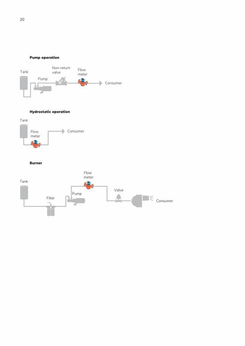
Consumer
Tank
Pump
Non-returnvalve
Flowmeter
Consumer
Tank
Flowmeter
Valve
ConsumerFilter
Flowmeter
Tank
Pump
Pump operation
Hydrostatic operation
Burner

21
22
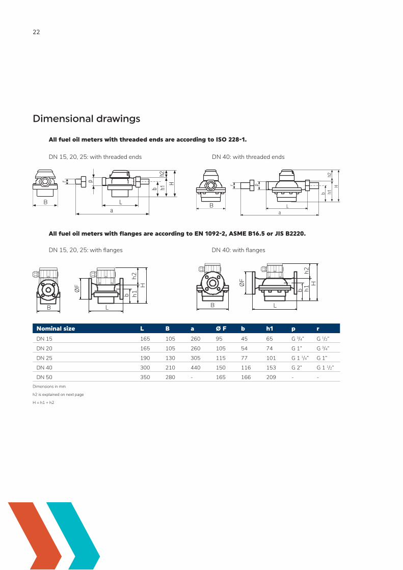
Dimensional drawings
All fuel oil meters with threaded ends are according to ISO 228-1.
All fuel oil meters with flanges are according to EN 1092-2, ASME B16.5 or JIS B2220.
Nominal size L B a Ø F b h1 p r
DN 15 165 105 260 95 45 65 G 3/4” G 1/2”
DN 20 165 105 260 105 54 74 G 1” G 3/4”
DN 25 190 130 305 115 77 101 G 1 1/4” G 1”
DN 40 300 210 440 150 116 153 G 2” G 1 1/2”
DN 50 350 280 - 165 166 209 - -Dimensions in mm
h2 is explained on next page
H = h1 + h2
B B
ØF
B L
b h1h2
H ØF
B Lb h1
h2H
DN 40: with threaded endsDN 15, 20, 25: with threaded ends
DN 40: with flangesDN 15, 20, 25: with flanges
23
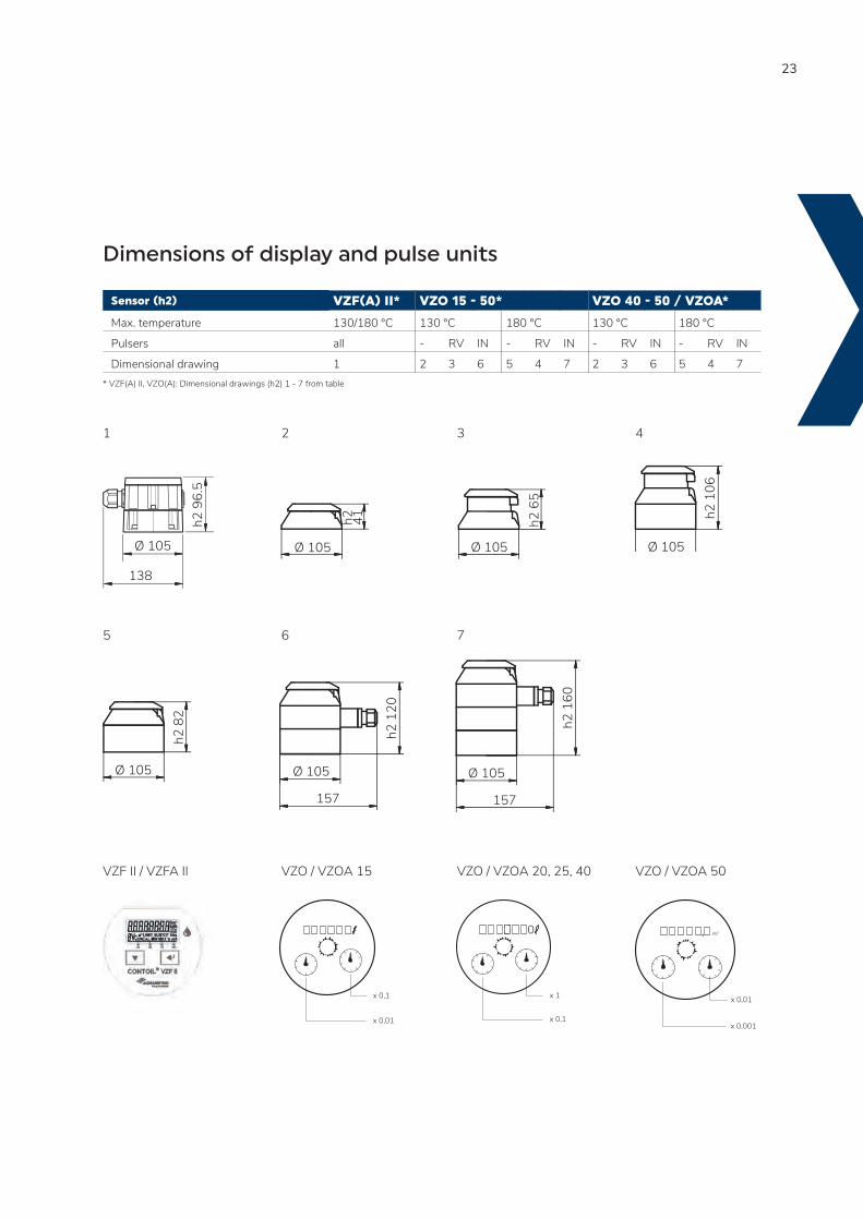
Dimensions of display and pulse units
Sensor (h2) VZF(A) II* VZO 15 - 50* VZO 40 - 50 / VZOA*
Max. temperature 130/180 °C 130 °C 180 °C 130 °C 180 °C
Pulsers all - RV IN - RV IN - RV IN - RV IN
Dimensional drawing 1 2 3 6 5 4 7 2 3 6 5 4 7* VZF(A) II, VZO(A): Dimensional drawings (h2) 1 - 7 from table
1 2 3 4
5 6 7
VZF II / VZFA II VZO / VZOA 15 VZO / VZOA 20, 25, 40 VZO / VZOA 50
Ø 105
h2 8
2
157
Ø 105
h2 1
20
157
Ø 105
h2 1
60
0
x 0,1
x 1
m3,
x 0,01
x 0,001
Ø 105
h2
41
Ø 105h2
65
Ø 105
h2 1
06
138
Ø 105
h2 9
6.5
x 0,1
x 0,01
24
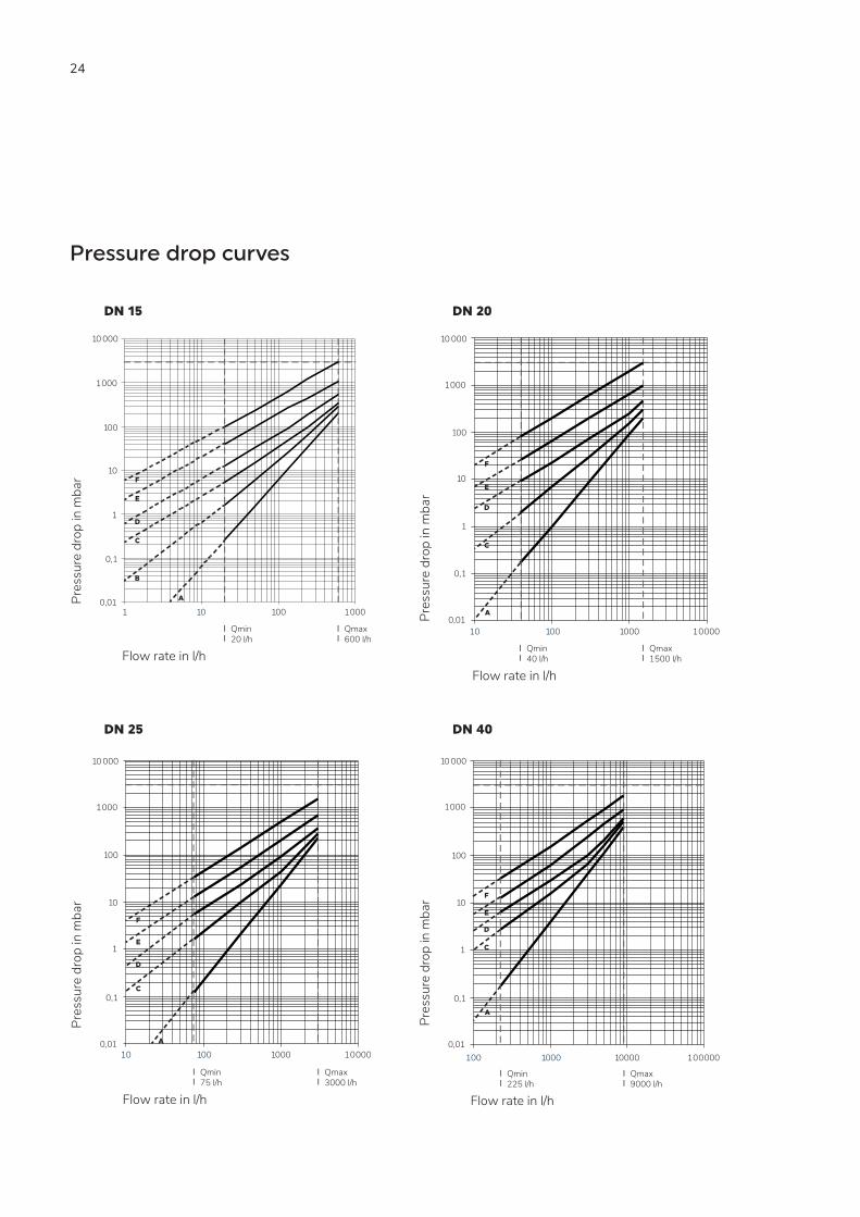
Pressure drop curves
DN 15 DN 20
DN 25 DN 40
10 000
1000
100
10
F
E
D1
C
0,1
B
A0,01
Flow rate in l/h
1 10 100
1000
Pres
sure
dro
p in
mba
r
Qmax 600 l/h
Qmin20 l/h
10 000
1000
100
10
0,1
0,01
Flow rate in l/h
10 100 1000 10000
Pres
sure
dro
p in
mba
r
Qmax 1500 l/h
Qmin40 l/h
1
F
E
D
C
A
10 000
1000
100
10
1
0,1
0,01
Flow rate in l/h
Pres
sure
dro
p in
mba
r
Qmax 3000 l/h
Qmin75 l/h
10 100 1000 10000
F
E
D
C
A
10 000
1000
100
10
1
0,1
0,01
Flow rate in l/h
Pres
sure
dro
p in
mba
r
Qmax 9000 l/h
Qmin225 l/h
100 1000 10000 100000
F
E
D
C
A
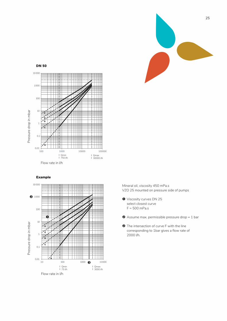
25
Mineral oil, viscosity 450 mPa.s VZO 25 mounted on pressure side of pumps
Viscosity curves DN 25 select closest curve F = 500 mPa.s
Assume max. permissible pressure drop = 1 bar
The intersection of curve F with the line corresponding to 1bar gives a flow rate of 2000 l/h.
DN 50
10 000
1000
100
10
1
0,1
0,01
Pres
sure
dro
p in
mba
r
Flow rate in l/h
100 1000 10000 100000
Qmax 30000 l/h
Qmin750 l/h
F
E
D
C
A
Example
10 000
1000
100
10
1
0,1
0,01
Flow rate in l/h
Pres
sure
dro
p in
mba
r
Qmax 3000 l/h
Qmin75 l/h
10 100 1000 10000
F
E
D
C
A
26
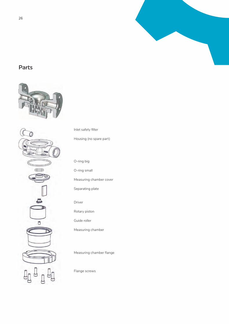
Parts
Inlet safety filter Housing (no spare part)
O-ring big O-ring small Measuring chamber cover Separating plate
Driver Rotary piston Guide roller Measuring chamber Measuring chamber flange Flange screws
27
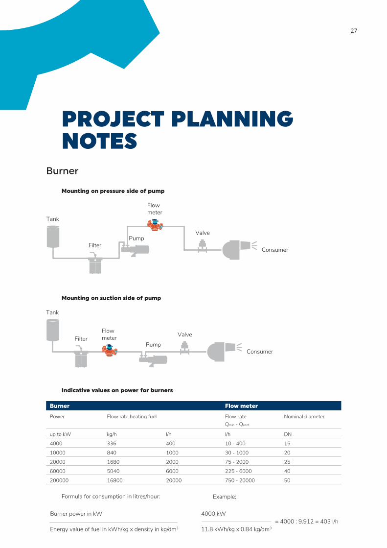
PROJECT PLANNING NOTES
Burner
Mounting on pressure side of pump
Mounting on suction side of pump
Indicative values on power for burners
Burner Flow meter
Power Flow rate heating fuel Flow rateQmin - Qcont
Nominal diameter
up to kW kg/h l/h l/h DN
4000 336 400 10 - 400 15
10000 840 1000 30 - 1000 20
20000 1680 2000 75 - 2000 25
60000 5040 6000 225 - 6000 40
200000 16800 20000 750 - 20000 50 Formula for consumption in litres/hour:
Valve
ConsumerFilter
Flowmeter
Tank
Pump
Filter
Flowmeter
Valve
Tank
PumpConsumer
Burner power in kW Energy value of fuel in kWh/kg x density in kg/dm3
Example:
4000 kW = 4000 : 9.912 = 403 l/h 11.8 kWh/kg x 0.84 kg/dm3
28
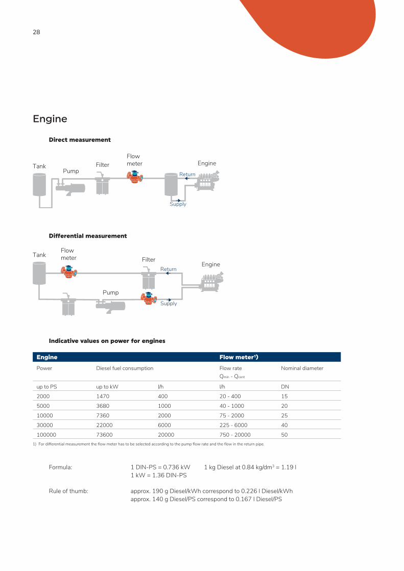
Engine
Direct measurement
Differential measurement Indicative values on power for engines
Engine Flow meter¹)
Power Diesel fuel consumption Flow rateQmin - Qcont
Nominal diameter
up to PS up to kW l/h l/h DN
2000 1470 400 20 - 400 15
5000 3680 1000 40 - 1000 20
10000 7360 2000 75 - 2000 25
30000 22000 6000 225 - 6000 40
100000 73600 20000 750 - 20000 501) For differential measurement the flow meter has to be selected according to the pump flow rate and the flow in the return pipe.
Formula: 1 DIN-PS = 0.736 kW 1 kg Diesel at 0.84 kg/dm3 = 1.19 l 1 kW = 1.36 DIN-PS
Rule of thumb: approx. 190 g Diesel/kWh correspond to 0.226 l Diesel/kWh approx. 140 g Diesel/PS correspond to 0.167 l Diesel/PS
Engine
Return
Supply
FilterFlowmeterTank
Pump
EngineReturn
Supply
FilterFlowmeterTank
Pump
29
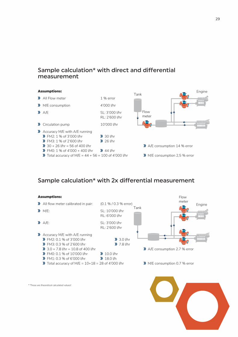
Sample calculation* with direct and differential measurement
Assumptions:
All Flow meter 1 % error
M/E consumption 4’000 l/hr
A/E SL: 3’000 l/hr RL: 2’600 l/hr
Circulation pump 10’000 l/hr
Accuracy M/E with A/E running FM2: 1 % of 3’000 l/hr 30 l/hr FM3: 1 % of 2’600 l/hr 26 l/hr 30 + 26 l/hr = 56 of 400 l/hr A/E consumption 14 % error FM0: 1 % of 4’000 + 400 l/hr 44 l/hr Total accuracy of M/E = 44 + 56 = 100 of 4’000 l/hr M/E consumption 2,5 % error
Sample calculation* with 2x differential measurement
Assumptions:
All flow meter calibrated in pair: (0.1 % / 0.3 % error)
M/E: SL: 10’000 l/hr RL: 6‘000 l/hr
A/E: SL: 3‘000 l/hr RL: 2‘600 l/hr
Accuracy M/E with A/E running FM2: 0.1 % of 3’000 l/hr 3.0 l/hr FM3: 0.3 % of 2’600 l/hr 7.8 l/hr 3.0 + 7.8 l/hr = 10.8 of 400 l/hr A/E consumption 2.7 % error FM0: 0.1 % of 10’000 l/hr 10.0 l/hr FM1: 0.3 % of 6’000 l/hr 18.0 l/h Total accuracy of M/E = 10+18 = 28 of 4’000 l/hr M/E consumption 0.7 % error
* These are theoretical calculated values!
Engine
Flowmeter
Tank
Engine
Flowmeter
Tank

30
Sample calculation* for differential measurement - standard vs paired flow meters
Assumptions:
Standard calibration 1 % error (CONTOIL® VZF II): Supply (FM0) 10’000 l/h ±1 % = ±100 l/h Return (FM1) 10’000 l/h ±1 % = ±100 l/h
Max. difference 2 % = 200 l/h
Pair calibration 0.1 % + 0.3 % error (CONTOIL® VZFA II): Supply (FM0) 10’000 l/h ± 0.1 % = ±10 l/h Return (FM1) 10’000 l/h ± 0.3 % = ±30 l/h
Max. difference 0.4 % = 40 l/h
* These are theoretical calculated values!
EngineReturn
Supply
FilterFlowmeterTank
Pump

31
Negative influencing factors List of factors which can influence the performance of the flow meter negatively: Medium Mechanical Specification
Seawater Pulsating pressure Dimension too big Acid Cat fines Over temperature Cleaning products Pre-filter mesh size
After any modification of the pipe system the system has to be cleaned / flushed without the flow meter installed to prevent any damage to the flow meter from any debris.
Temperature compensation
The installation of temperature sensors at the flow meter positions is absolutely essential, without temperature compensation of the flow meter data, the error in the measurement can become extremely large, depending on the process conditions. As a rule of thumb we assume almost 1 % volume difference for each 10 °C temperature difference. (Usually there is a temperature difference between the oil in the supply line and in the return line.)
Density compensation
If fuel oil consumption in mass needs to be compared instead of volume, it is important to know that the mass is changing with the density, which itself is changing with the temperature. To obtain most precise measurement results, it is recommended to measure the online density on board. If there is no sensor available, you have to use the density which is given in each bunkering report and calculate volume values at different temperatures back to the corresponding mass values. However there are differences in HFO quality across the world and you should consider that the density mentioned on the bunkering report refers to the required specification.
The CONTOIL® VZF II is able to calculate the mass flow with a given density, adjusted by the measured medium temperature built in the flow meter.
These calculations are done according to DIN 51757.
32
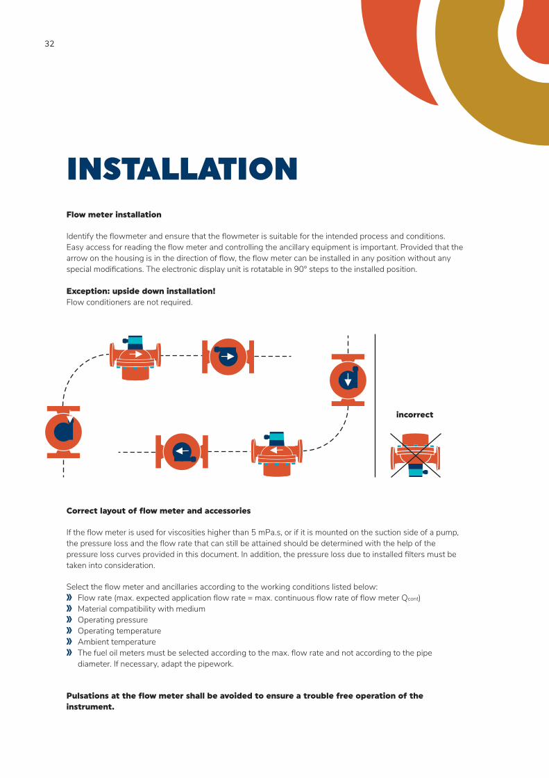
INSTALLATION Flow meter installation
Identify the flowmeter and ensure that the flowmeter is suitable for the intended process and conditions. Easy access for reading the flow meter and controlling the ancillary equipment is important. Provided that the arrow on the housing is in the direction of flow, the flow meter can be installed in any position without any special modifications. The electronic display unit is rotatable in 90° steps to the installed position. Exception: upside down installation! Flow conditioners are not required.
←
←
←
←←
←
Correct layout of flow meter and accessories
If the flow meter is used for viscosities higher than 5 mPa.s, or if it is mounted on the suction side of a pump, the pressure loss and the flow rate that can still be attained should be determined with the help of the pressure loss curves provided in this document. In addition, the pressure loss due to installed filters must be taken into consideration.
Select the flow meter and ancillaries according to the working conditions listed below: Flow rate (max. expected application flow rate = max. continuous flow rate of flow meter Qcont) Material compatibility with medium Operating pressure Operating temperature Ambient temperature The fuel oil meters must be selected according to the max. flow rate and not according to the pipe
diameter. If necessary, adapt the pipework.
Pulsations at the flow meter shall be avoided to ensure a trouble free operation of the instrument.
incorrect
33
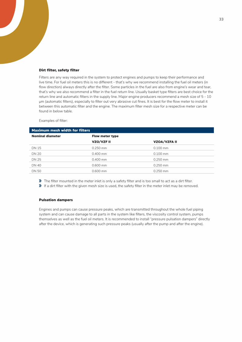
Dirt filter, safety filter
Filters are any way required in the system to protect engines and pumps to keep their performance and live time. For fuel oil meters this is no different - that’s why we recommend installing the fuel oil meters (in flow direction) always directly after the filter. Some particles in the fuel are also from engine’s wear and tear, that’s why we also recommend a filter in the fuel return line. Usually basket type filters are best choice for the return line and automatic filters in the supply line. Major engine producers recommend a mesh size of 5 - 10 μm (automatic filters), especially to filter out very abrasive cut fines. It is best for the flow meter to install it between this automatic filter and the engine. The maximum filter mesh size for a respective meter can be found in below table.
Examples of filter:
Maximum mesh width for filters
Nominal diameter Flow meter type
VZO/VZF II VZOA/VZFA II
DN 15 0.250 mm 0.100 mm
DN 20 0.400 mm 0.100 mm
DN 25 0.400 mm 0.250 mm
DN 40 0.600 mm 0.250 mm
DN 50 0.600 mm 0.250 mm
The filter mounted in the meter inlet is only a safety filter and is too small to act as a dirt filter. If a dirt filter with the given mesh size is used, the safety filter in the meter inlet may be removed.
Pulsation dampers
Engines and pumps can cause pressure peaks, which are transmitted throughout the whole fuel piping system and can cause damage to all parts in the system like filters, the viscosity control system, pumps themselves as well as the fuel oil meters. It is recommended to install “pressure pulsation dampers” directly after the device, which is generating such pressure peaks (usually after the pump and after the engine).
34
Pressure Loss
For the dimensioning of oil meters not only the flow rate, but also the pressure loss is important. All components in the fuel piping system and the piping layout itself cause a pressure loss. In general a higher flow and a higher viscosity cause a higher pressure loss over the flow meter. Piping bends, valves, reduction of pipes, as well as strainers and fuel oil meters do also have a pressure loss, which must be taken into account when dimensioning the fuel supply system. Please check the pressure drop at each flow meter with the help of the pressure drop curves. For a pressure drop of more than 1 bar, it is recommended to use the next larger flow meter size.
Ideally the fuel oil meters are installed on the pressure side of the pump.
If the fuel oil meters are on the suction side of the pump there is under pressure, which can cause out-gassing of the oil (1 % gas in the oil causes 1 % measurement failure).
Depending on the viscosity of the oil it is adviced to check the pressure loss and decide if there is still enough pressure after the flow meter.
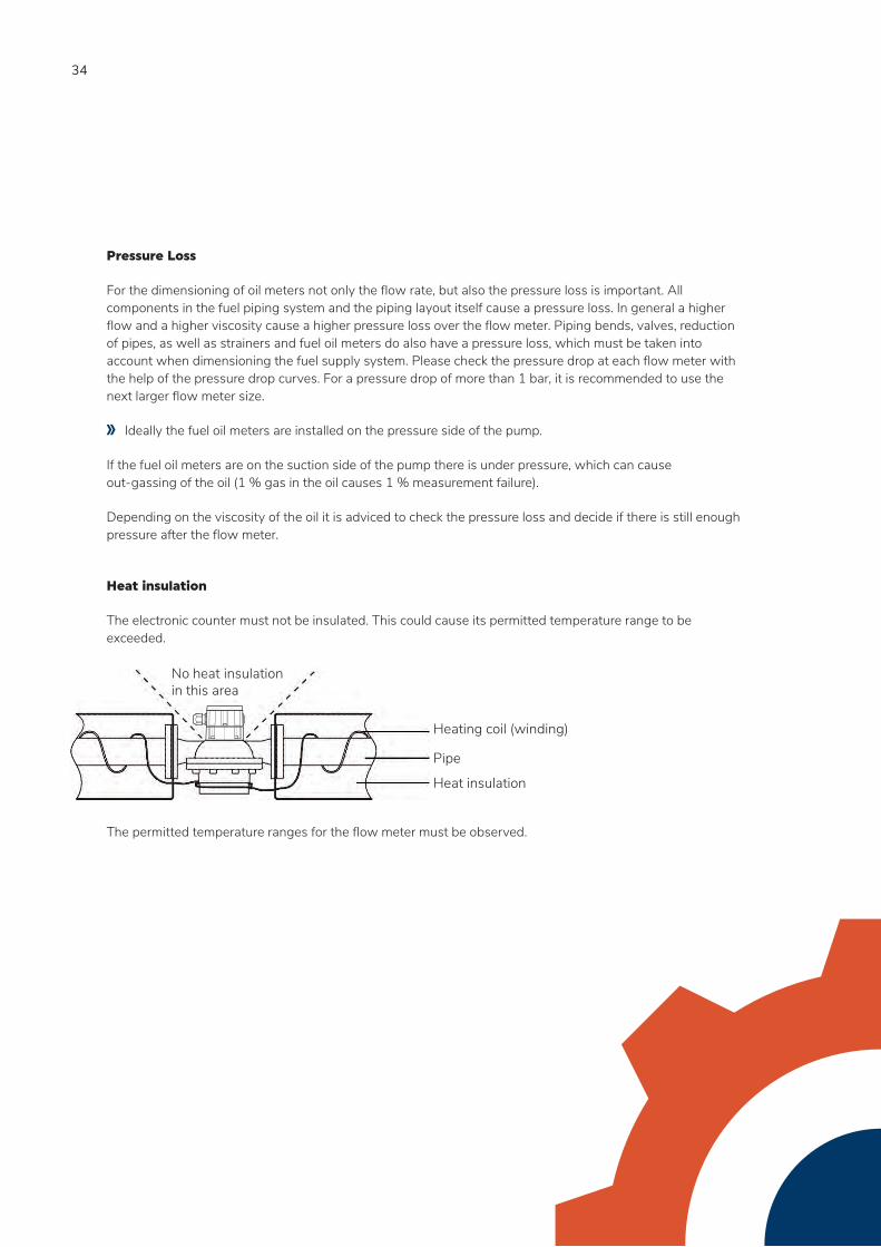
Heat insulation
The electronic counter must not be insulated. This could cause its permitted temperature range to be exceeded. The permitted temperature ranges for the flow meter must be observed.
No heat insulation in this area
Pipe
Heat insulation
Heating coil (winding)

35
Special requirements - ships
On ships, attention is required to ensure that the engine can continue to operate at full power even if there is heavy filter contamination or if the flow meter requires maintenance. A pressure switch or a manual valve can be used to switch over to the bypass and to draw attention for servicing. The engine then continues to operate without consumption measurements.
Ship classification societies require the installation of bypass pipes. The relevant regulations must be followed.
Valve EngineFilter
Flowmeter
Tank Pump
IASMonitor
Valve EngineFilterFlowmeter
Tank Pump
IASMonitor
Return
Supply
36
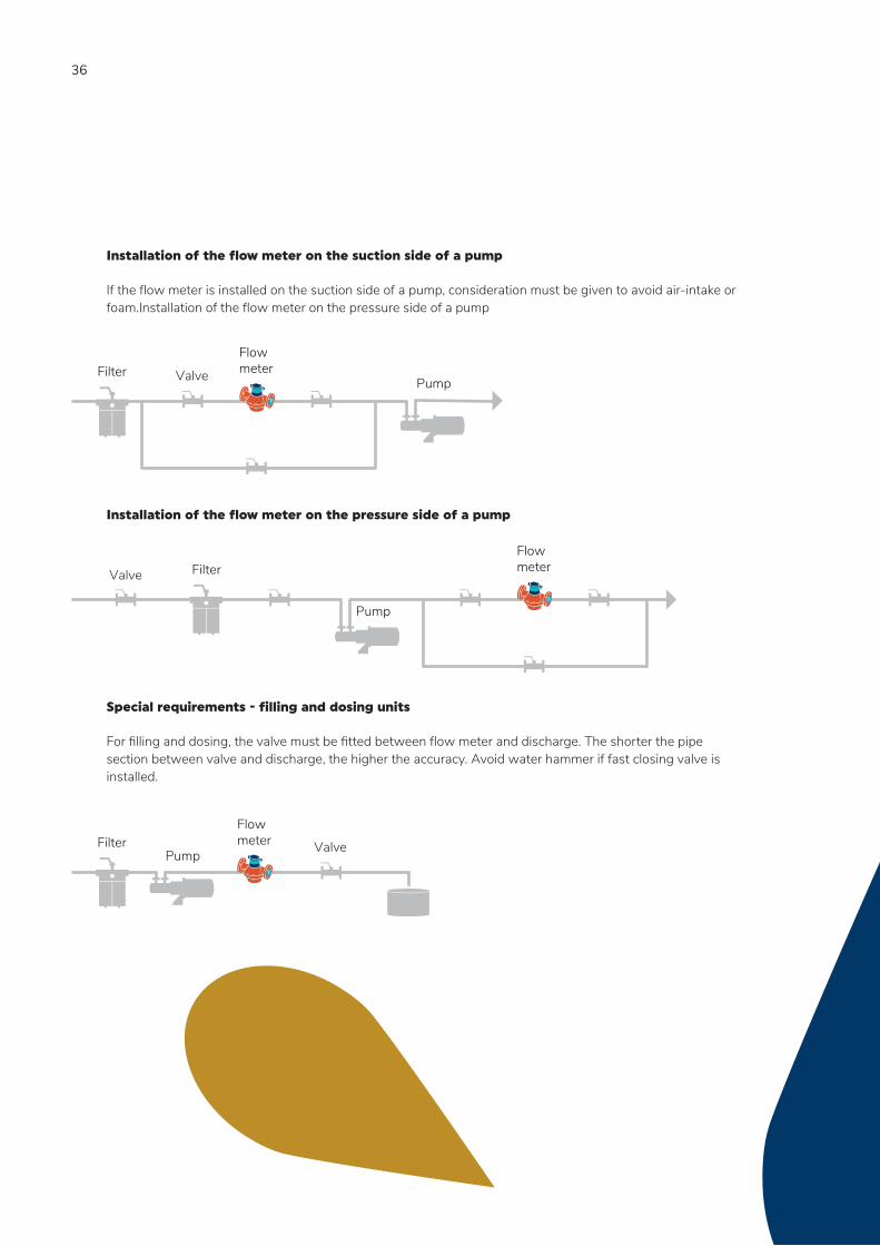
Installation of the flow meter on the suction side of a pump
If the flow meter is installed on the suction side of a pump, consideration must be given to avoid air-intake or foam.Installation of the flow meter on the pressure side of a pump
Installation of the flow meter on the pressure side of a pump
Special requirements - filling and dosing units
For filling and dosing, the valve must be fitted between flow meter and discharge. The shorter the pipe section between valve and discharge, the higher the accuracy. Avoid water hammer if fast closing valve is installed.
FlowmeterFilter
PumpValve
Valve FilterFlowmeter
Pump
FilterFlowmeter
Pump Valve
37
WARRANTY, SAFETY INSTRUCTIONS Warranty Disclaimer
Aquametro Oil & Marine guarantees the quality of the product in the context of its General Terms of Business. The owner, operator or installer will be liable for the correct installation as well as the appropriate handling of the equipment upon its receipt.
Please observe the application-, mounting- and operation-instructions. Use the unit exclusively for its designed purpose. Maintain the unit and service it according to prescriptions. Use accessories only if their applicability is technically safe.
Safety rules and precautionary measures
The manufacturer accepts no responsibility if the following safety rules and precautions are disregarded. Modifications of the device implemented without preceding written consent from the manufacturer, will
result in the immediate termination of product liability and warranty period. Installation, operation, maintenance and decommissioning of this device must be carried out by trained,
qualified specialists, authorized by the manufacturer, operator or owner of the facility. The specialist must have read and understood these mounting- and operating-instructions and must follow the instructions here in.
Check the voltage and the information on the type plate before installing the device. Check all connections, settings and technical specifications of peripherals which may be present. Open the housing or parts of housings, which electric or electronic components included, only when the
electric power is turned off. Do not touch any electronic components (ESD sensitivity). Expose the system with respect to the mechanical load (pressure, temperature, IP protection, etc.), only to
a maximum of the specified classifications. During operations that involve mechanical components of the system, release the pressure in the pipe
system or reduce the temperature of the medium to a safe level for humans. None of the information stated here or elsewhere releases planners, installers and operators from their
own careful and comprehensive assessment of the respective system configuration in terms of functional capability and operational safety.
The local labor, safety laws and regulations must be adhered to.
38
CERTIFICATES Det Norske Veritas - German Lloyd Norway - Germany
Lloyds Register United Kingdom
RRR Russian River Register
RMRS Russian Maritime Register of Shipping

39

Aquametro Oil & Marine GmbHDE-18119 Rostock, [email protected] +49 381 382 530 00www.aquametro-oil-marine.com
Aquametro Oil & Marine AG CH-4106 Therwil, [email protected] Phone +41 61 725 44 00 V
D 4
-300
e 0
7.20
19Th
e en
glis
h ve
rsio
n sh
all p
reva
il. Su
bjec
t to
chan
ge w
ithou
t not
ice.
A
ll in
telle
ctua
l pro
pert
y rig
hts
are
excl
usiv
ely
with
Aqu
amet
ro O
il &
Mar
ine
AG
, Sw
itzer
land