KAORI Brazed Plate Heat Exchanger Double Wall Heat Exchanger
Upload
truongthuanCategory
view
222download
0
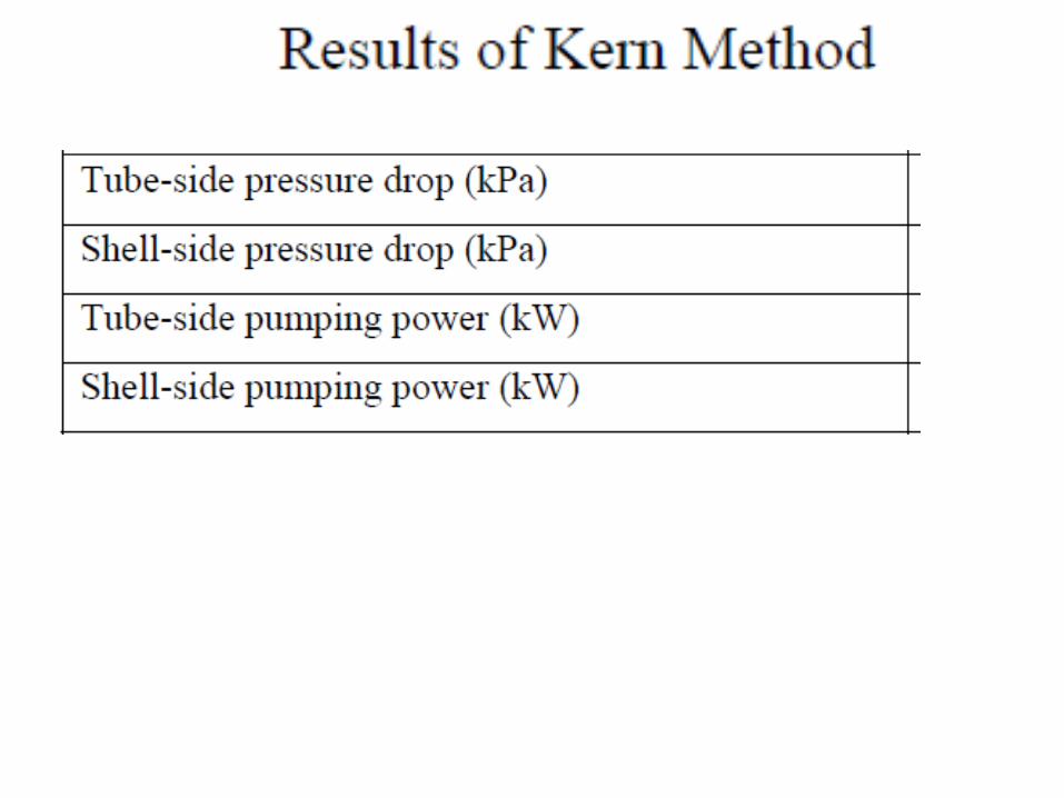
Kern Method of SHELL-AND-TUBE HEAT EXCHANGER Analysis
P M V SubbaraoProfessor
Mechanical Engineering DepartmentI I T Delhi
Simplified Procedures using Semi- Empirical Correlations.….
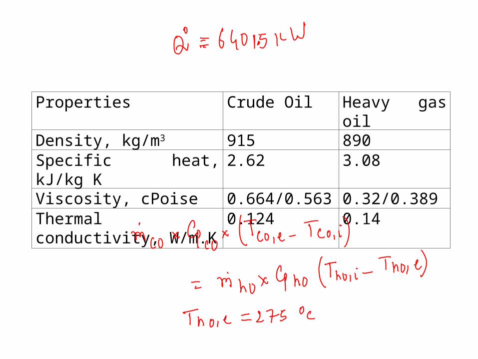
Properties Crude Oil Heavy gas oilDensity, kg/m3 915 890Specific heat, kJ/kg K 2.62 3.08Viscosity, cPoise 0.664/0.563 0.32/0.389Thermal conductivity, W/m.K
0.124 0.14
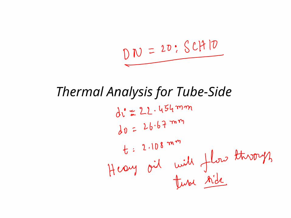
Thermal Analysis for Tube-Side
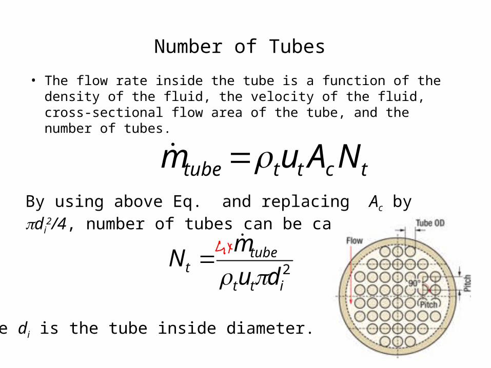
Number of Tubes • The flow rate inside the tube is a function of the density of the
fluid, the velocity of the fluid, cross-sectional flow area of the tube, and the number of tubes.
By using above Eq. and replacing Ac by di2/4, number of tubes
can be calculated as
2itt
tubet du
mN
tctttube NAum
where di is the tube inside diameter.
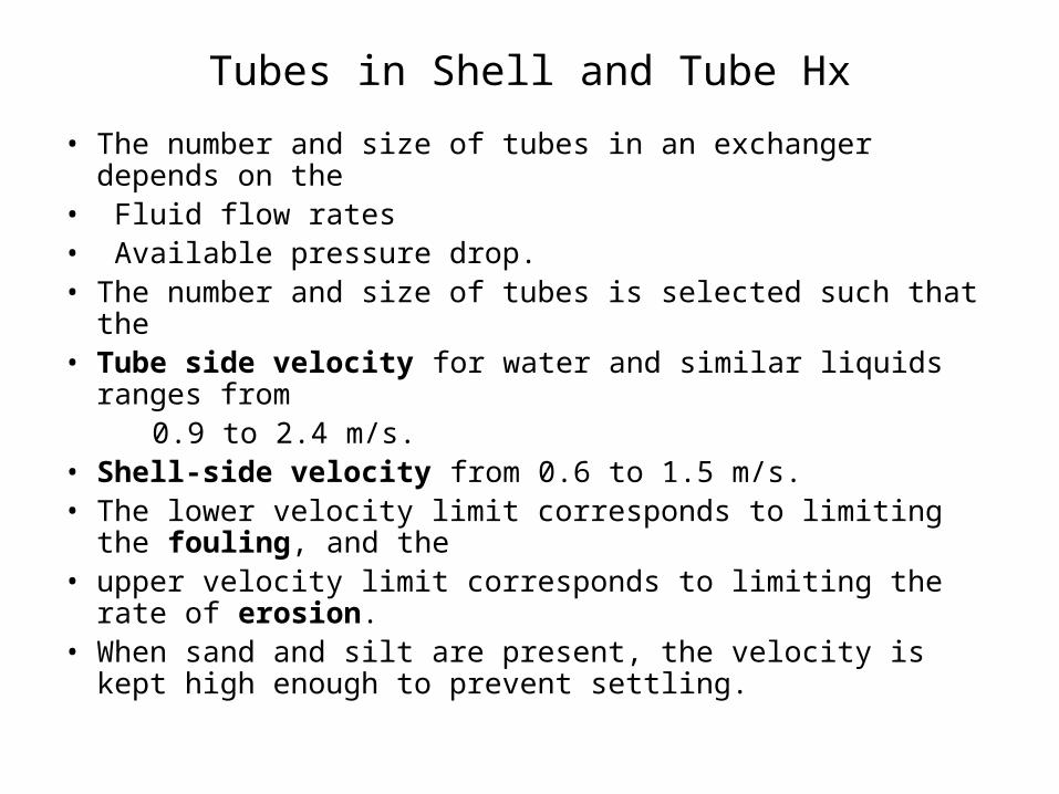
Tubes in Shell and Tube Hx
• The number and size of tubes in an exchanger depends on the• Fluid flow rates• Available pressure drop.• The number and size of tubes is selected such that the• Tube side velocity for water and similar liquids ranges from 0.9 to 2.4 m/s.• Shell-side velocity from 0.6 to 1.5 m/s.• The lower velocity limit corresponds to limiting the fouling,
and the• upper velocity limit corresponds to limiting the rate of
erosion.• When sand and silt are present, the velocity is kept high
enough to prevent settling.
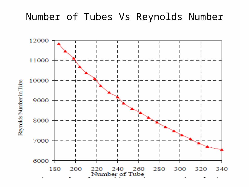
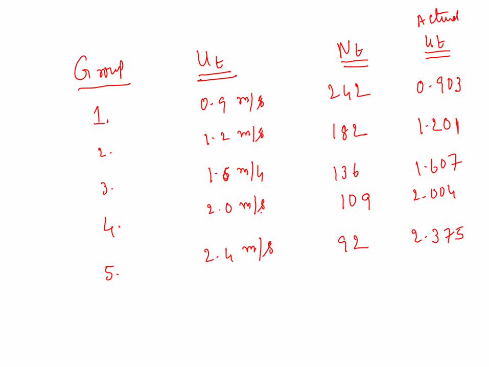
Number of Tubes Vs Reynolds Number
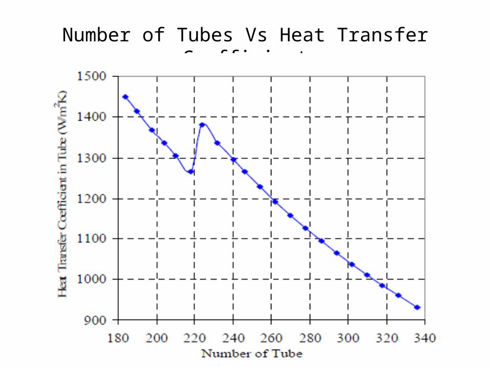
Number of Tubes Vs Heat Transfer Coefficient
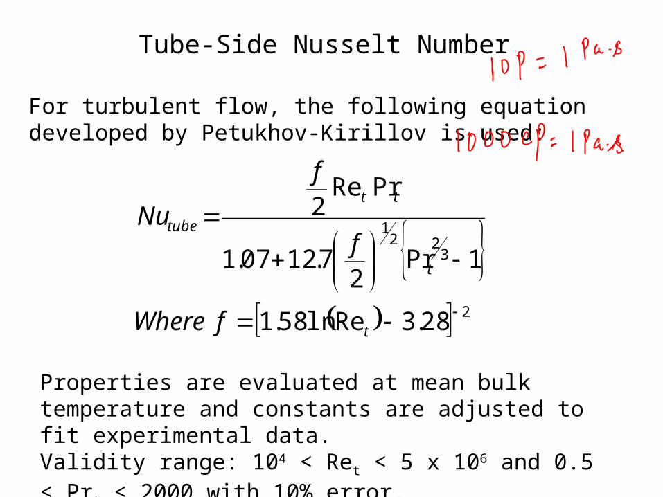
Tube-Side Nusselt Number
For turbulent flow, the following equation developed by Petukhov-Kirillov is used:
2
322
1
28.3Reln58.1
1Pr2
7.1207.1
PrRe2
t
t
tt
tube
fWhere
f
f
Nu
Properties are evaluated at mean bulk temperature and constants are adjusted to fit experimental data.Validity range: 104 < Ret < 5 x 10⁶ and 0.5 < Prt < 2000 with 10% error.
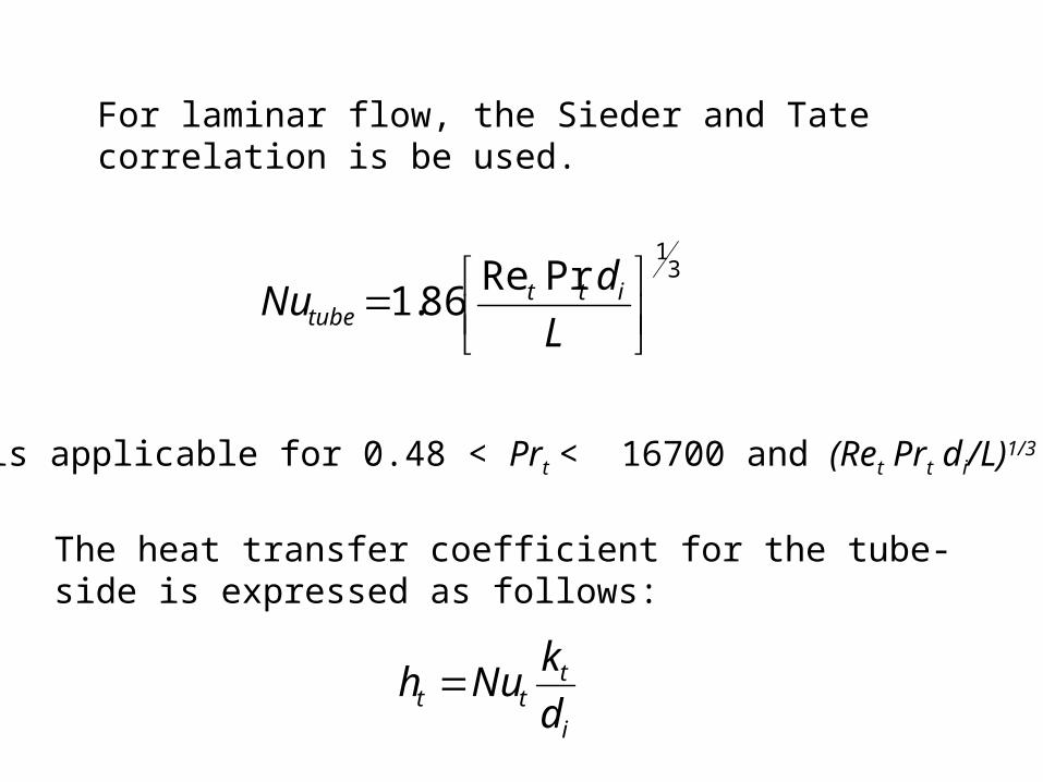
For laminar flow, the Sieder and Tate correlation is be used.
31
PrRe86.1
LdNu itt
tube
is applicable for 0.48 < Prt < 16700 and (Ret Prt di/L)1/3 > 2.
The heat transfer coefficient for the tube-side is expressed as follows:
i
ttt d
kNuh

Thermal Analysis for Shell-Side
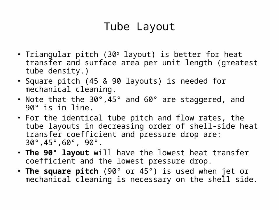
Tube Layout
• Triangular pitch (30o layout) is better for heat transfer and surface area per unit length (greatest tube density.)
• Square pitch (45 & 90 layouts) is needed for mechanical cleaning.
• Note that the 30°,45° and 60° are staggered, and 90° is in line.• For the identical tube pitch and flow rates, the tube layouts in
decreasing order of shell-side heat transfer coefficient and pressure drop are: 30°,45°,60°, 90°.
• The 90° layout will have the lowest heat transfer coefficient and the lowest pressure drop.
• The square pitch (90° or 45°) is used when jet or mechanical cleaning is necessary on the shell side.
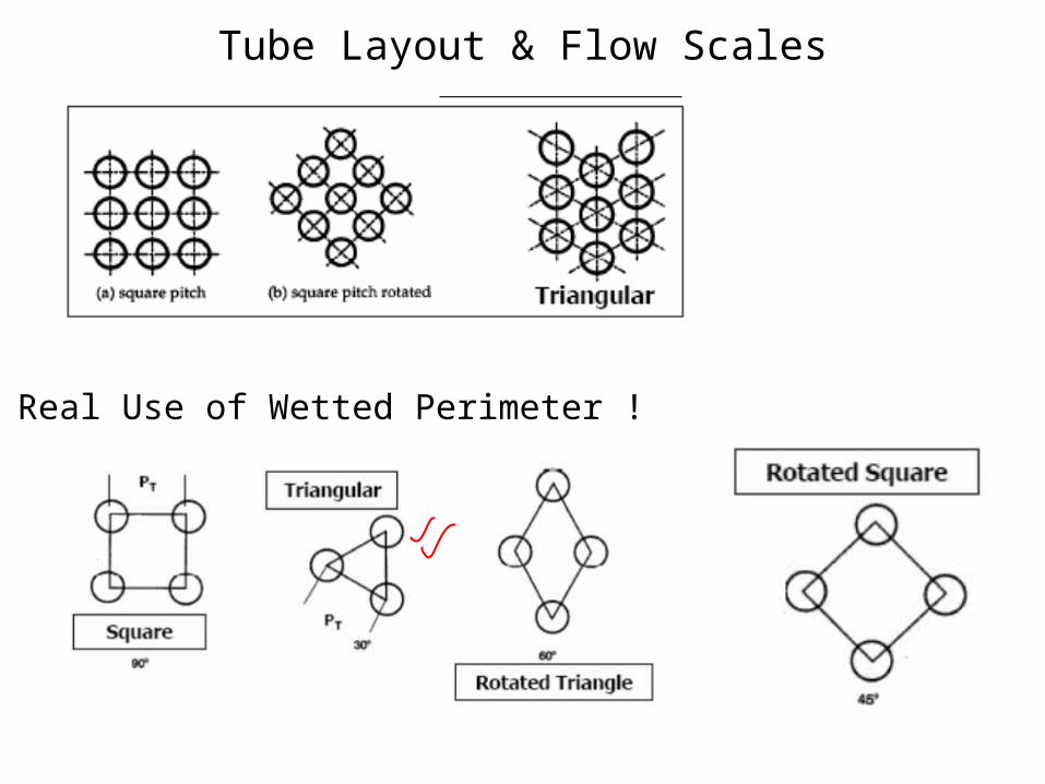
Tube Layout & Flow Scales
A Real Use of Wetted Perimeter !
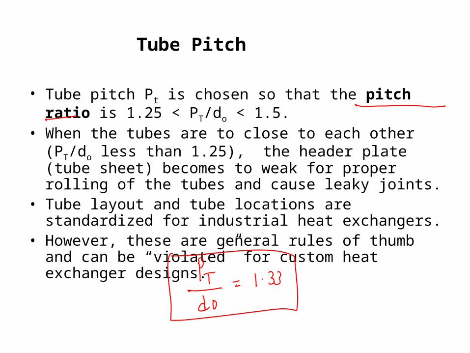
Tube Pitch
• Tube pitch Pt is chosen so that the pitch ratio is 1.25 < PT/do < 1.5.
• When the tubes are to close to each other (PT/do less than 1.25), the header plate (tube sheet) becomes to weak for proper rolling of the tubes and cause leaky joints.
• Tube layout and tube locations are standardized for industrial heat exchangers.
• However, these are general rules of thumb and can be “violated” for custom heat exchanger designs.
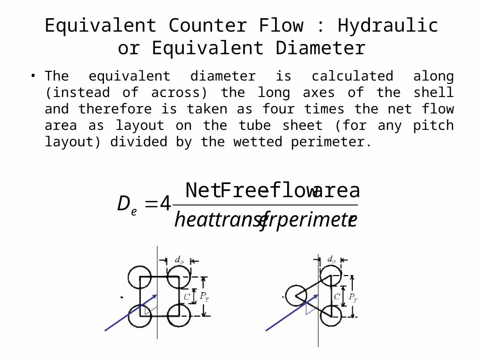
Equivalent Counter Flow : Hydraulic or Equivalent Diameter
• The equivalent diameter is calculated along (instead of across) the long axes of the shell and therefore is taken as four times the net flow area as layout on the tube sheet (for any pitch layout) divided by the wetted perimeter.
rerperimeteheattransfDe
area flow-FreeNet 4
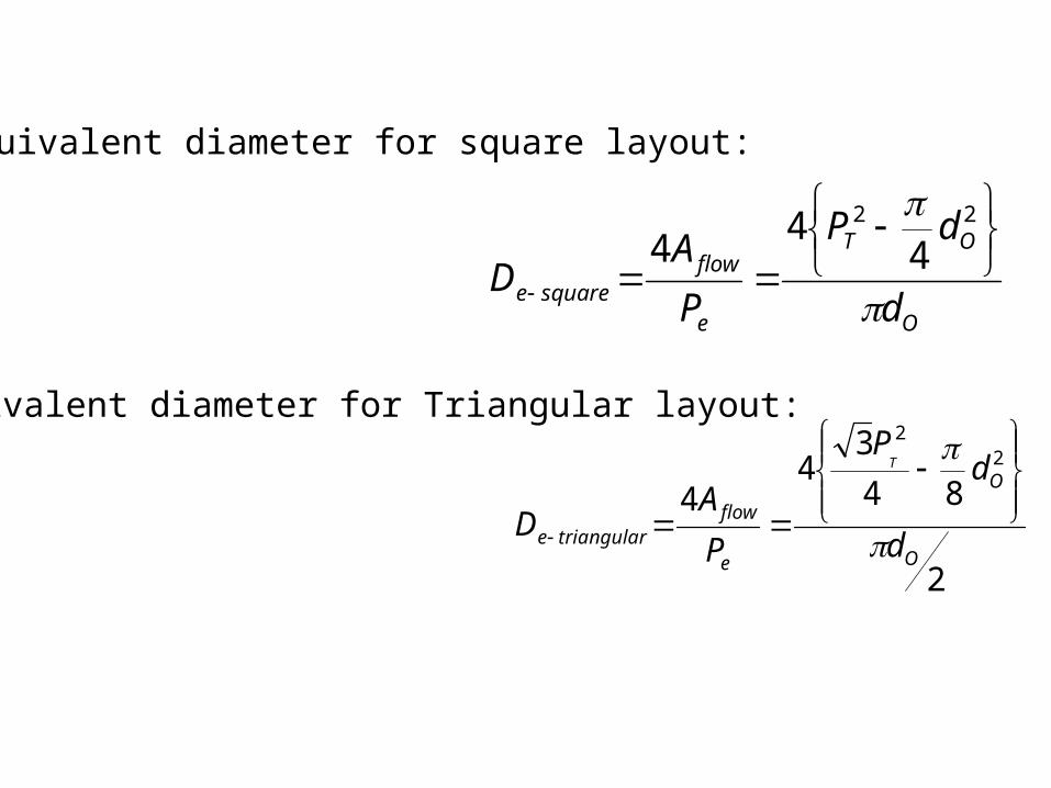
Equivalent diameter for square layout:
O
OT
e
flowsquaree d
dP
PA
D
22
444
Equivalent diameter for Triangular layout:
2
843
44
22
O
O
e
flowtriangulare d
dP
PA
D
T
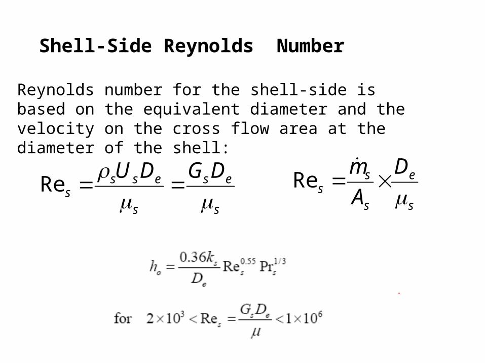
Shell-Side Reynolds Number
Reynolds number for the shell-side is based on the equivalent diameter and the velocity on the cross flow area at the diameter of the shell:
s
e
s
ss
DAm
Re
s
es
s
esss
DGDU
Re
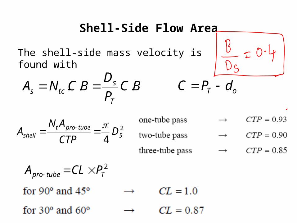
Shell-Side Flow Area
The shell-side mass velocity is found with
BCPDBCNA
T
stcs ... oT dPC
2
4 Stubeprot
shell DCTPAN
A
2Ttubepro PCLA
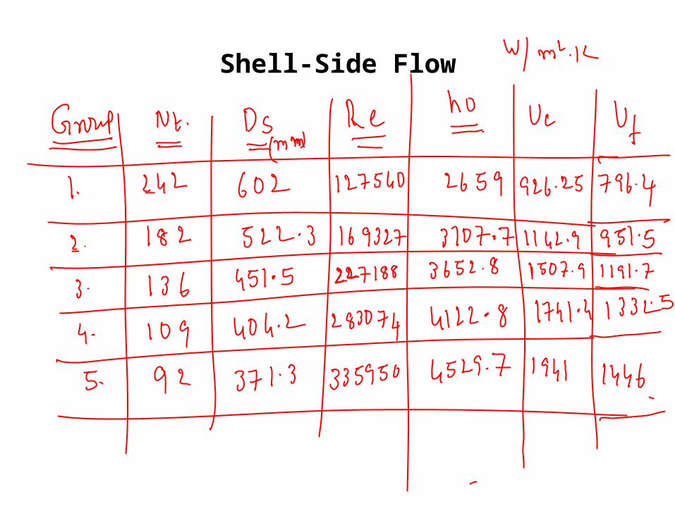
Shell-Side Flow
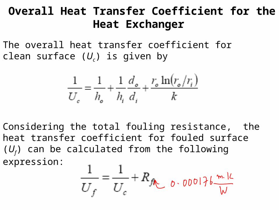
Overall Heat Transfer Coefficient for the Heat Exchanger
The overall heat transfer coefficient for clean surface (Uc) is given by
Considering the total fouling resistance, the heat transfer coefficient for fouled surface (Uf) can be calculated from the following expression:
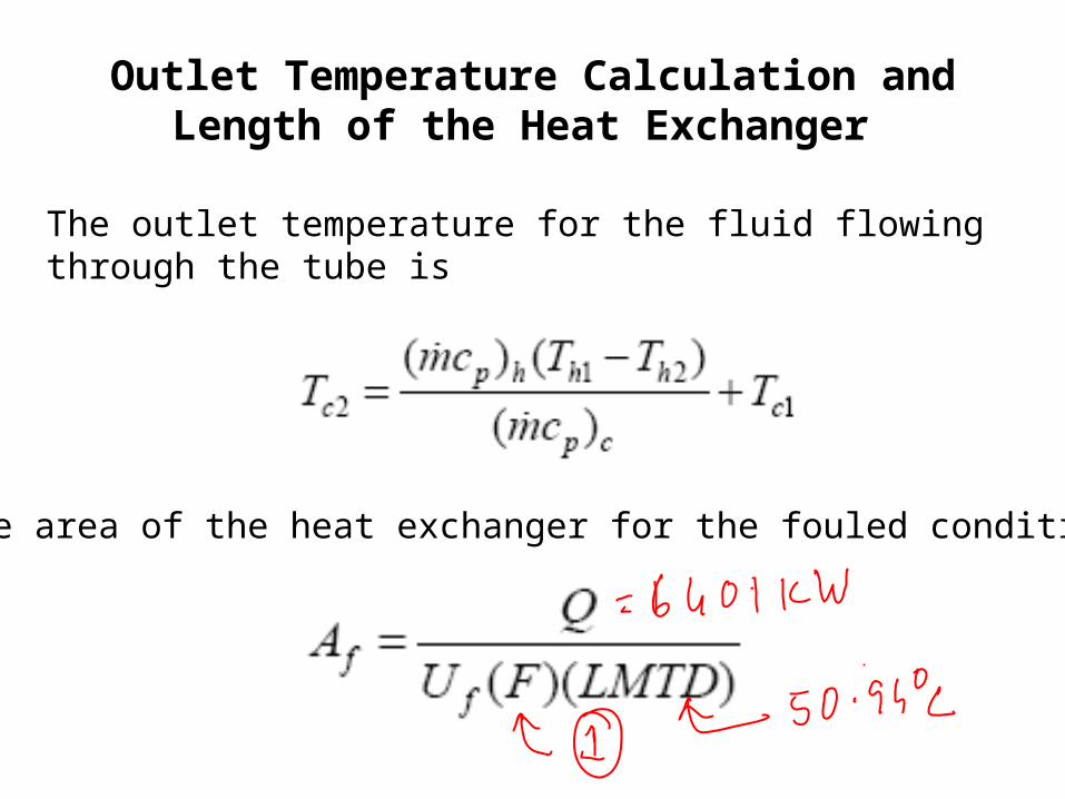
Outlet Temperature Calculation and Length of the Heat Exchanger
The outlet temperature for the fluid flowing through the tube is
The surface area of the heat exchanger for the fouled condition is :
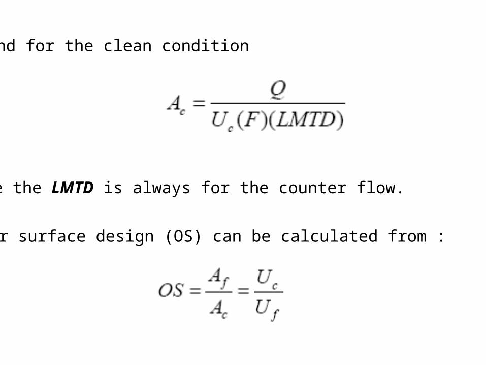
and for the clean condition
where the LMTD is always for the counter flow.
The over surface design (OS) can be calculated from :
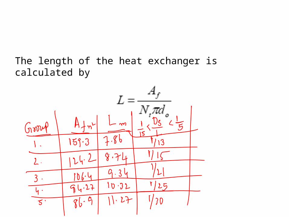
The length of the heat exchanger is calculated by
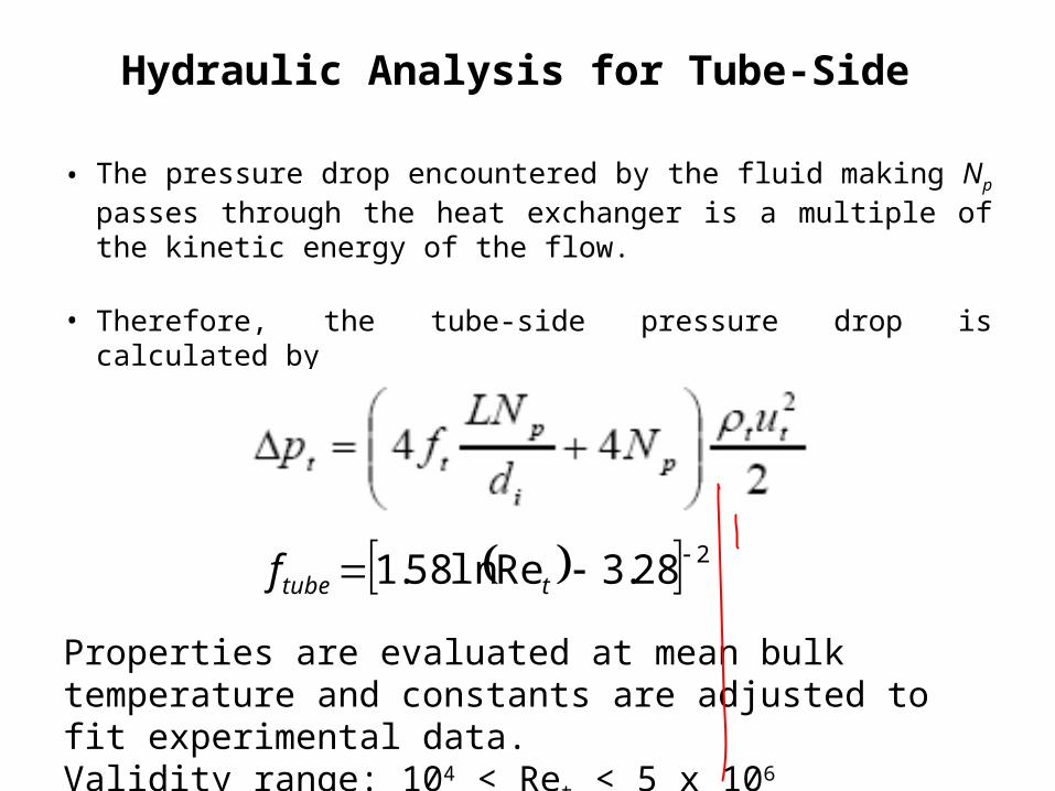
Hydraulic Analysis for Tube-Side
• The pressure drop encountered by the fluid making Np passes through the heat exchanger is a multiple of the kinetic energy of the flow.
• Therefore, the tube-side pressure drop is calculated by
228.3Reln58.1 ttubef
Properties are evaluated at mean bulk temperature and constants are adjusted to fit experimental data.Validity range: 104 < Ret < 5 x 10⁶
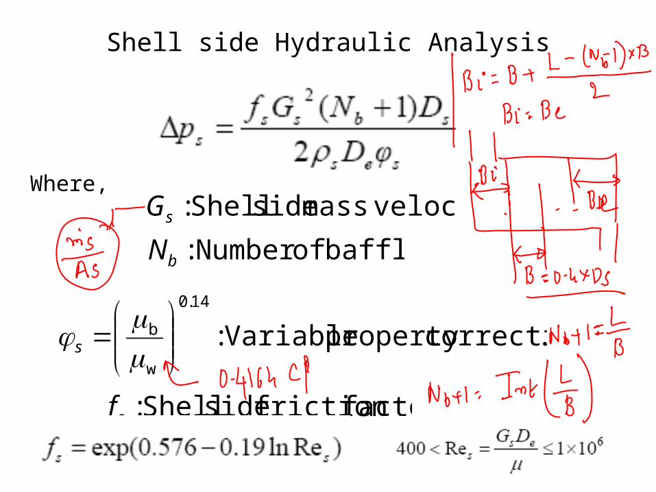
Where,
baffles ofNumber :bN velocitymass side Shell :sG
.correctionproperty Variable : 14.0
w
b
s
factorfriction side Shell :sf
Shell side Hydraulic Analysis
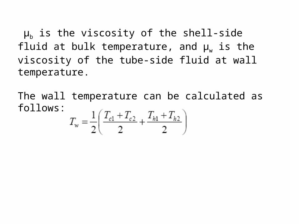
μb is the viscosity of the shell-side fluid at bulk temperature, and μw is the viscosity of the tube-side fluid at wall temperature.
The wall temperature can be calculated as follows:
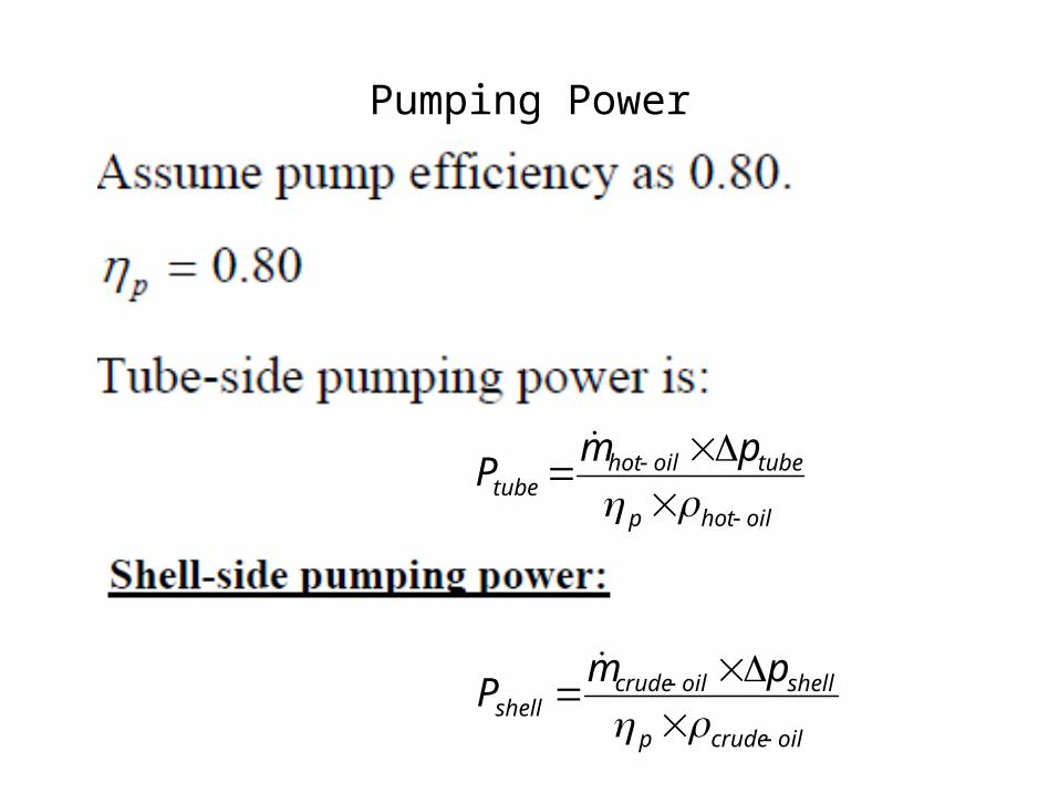
Pumping Power
oilhotp
tubeoilhottube
pmP
oilcrudep
shelloilcrudeshell
pmP
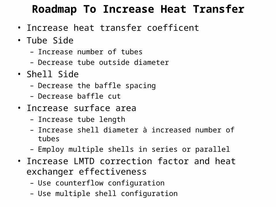
Roadmap To Increase Heat Transfer• Increase heat transfer coefficent• Tube Side
– Increase number of tubes– Decrease tube outside diameter
• Shell Side– Decrease the baffle spacing– Decrease baffle cut
• Increase surface area– Increase tube length– Increase shell diameter à increased number of tubes– Employ multiple shells in series or parallel
• Increase LMTD correction factor and heat exchanger effectiveness– Use counterflow configuration– Use multiple shell configuration
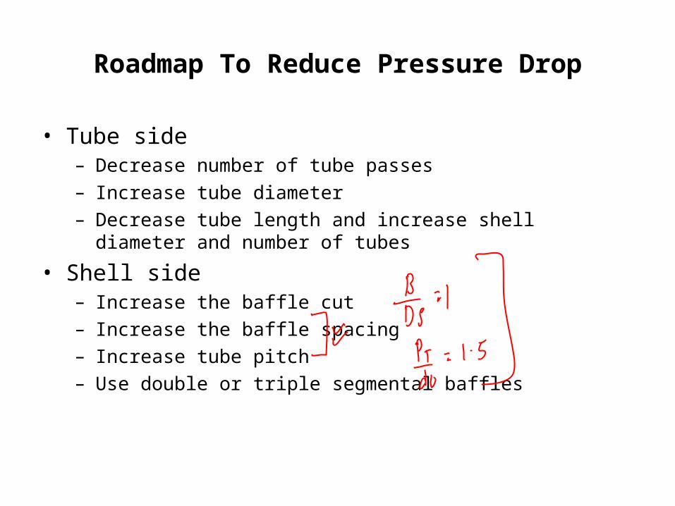
Roadmap To Reduce Pressure Drop
• Tube side– Decrease number of tube passes– Increase tube diameter– Decrease tube length and increase shell diameter and
number of tubes• Shell side
– Increase the baffle cut– Increase the baffle spacing– Increase tube pitch– Use double or triple segmental baffles
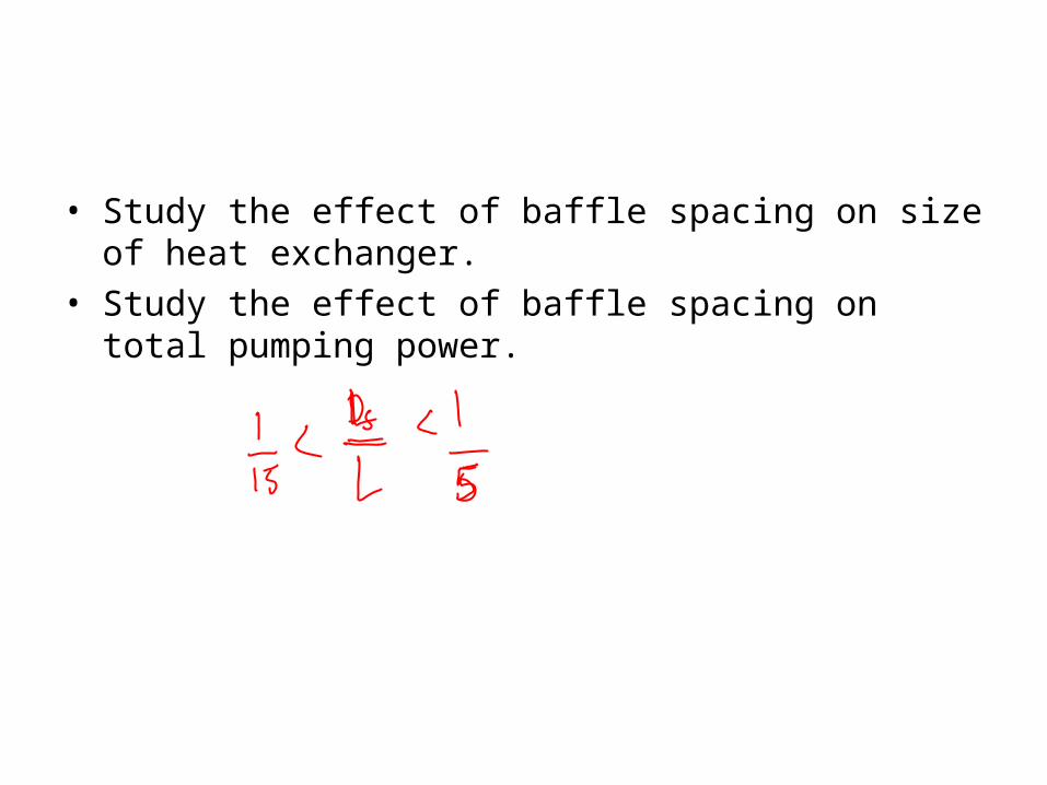
• Study the effect of baffle spacing on size of heat exchanger.
• Study the effect of baffle spacing on total pumping power.


![[PPT]ME421 Heat Exchanger and Steam Generator Designweb.iitd.ac.in/~pmvs/courses/mel709/mel709-tut10.ppt · Web viewTitle ME421 Heat Exchanger and Steam Generator Design Author tari](https://static.fdocuments.us/doc/165x107/5b0ba8aa7f8b9ac7678e8fec/pptme421-heat-exchanger-and-steam-generator-pmvscoursesmel709mel709-tut10pptweb.jpg)