ME 450 Final Report Bosch Spray Chamber April 23rd, 2015
67
ME 450 Final Report Bosch Spray Chamber April 23 rd , 2015 William Crowe: crowew James Gorton: jgorton Cameron Hoffman: hoffmcam Taylor Pomeroy: tpomeroy Section Instructor: Amy Hortop ME 450 W15 Section 2 - Team 3 ABSTRACT The purpose of this project is to develop the supporting hardware, software and systems to operate a spray chamber to enable the installation and operation of fuel injectors provided by Robert Bosch LLC. To configure the spray chamber for use at the Walter E. Lay Automotive Laboratory and GG Brown Building, we are expected to design and construct mounting hardware for the spray chamber to physically support the chamber on a cart or table, design and construct systems to supply inert gas to the chamber to pressurize the chamber, design and construct injector mounting hardware to install Bosch direct injection gasoline (GDI) fuel injectors in the chamber, and to design and construct systems to supply pressurized fuel to the injectors.
Transcript of ME 450 Final Report Bosch Spray Chamber April 23rd, 2015
ME 450 Final Report Bosch Spray Chamber
April 23rd, 2015
William Crowe: crowew James Gorton: jgorton
Cameron Hoffman: hoffmcam Taylor Pomeroy: tpomeroy
Section Instructor: Amy Hortop
ME 450 W15 Section 2 - Team 3
ABSTRACT The purpose of this project is to develop the supporting hardware, software and systems to operate a spray chamber to enable the installation and operation of fuel injectors provided by Robert Bosch LLC. To configure the spray chamber for use at the Walter E. Lay Automotive Laboratory and GG Brown Building, we are expected to design and construct mounting hardware for the spray chamber to physically support the chamber on a cart or table, design and construct systems to supply inert gas to the chamber to pressurize the chamber, design and construct injector mounting hardware to install Bosch direct injection gasoline (GDI) fuel injectors in the chamber, and to design and construct systems to supply pressurized fuel to the injectors.
CONTENTS PROBLEM DESCRIPTION AND BACKGROUND .............................................................................. 3
Alternative Solutions ................................................................................................................................ 4 Insufficiencies of Previous Work .............................................................................................................. 9
USER REQUIREMENTS AND ENGINEERING SPECIFICATIONS .............................................. 10 Rationale for Requirements .................................................................................................................... 12
CONCEPT GENERATION ..................................................................................................................... 14 Concept Categories ................................................................................................................................. 14 Concept Generation Methods ................................................................................................................. 14 Concepts Generated ................................................................................................................................ 14 Concept Selection Method ...................................................................................................................... 16
CHOSEN DESIGN ................................................................................................................................... 16 Fuel Supply System ................................................................................................................................ 17 Inert Gas Exchange ................................................................................................................................. 17 Controls System ...................................................................................................................................... 18 Test Bench .............................................................................................................................................. 19 Injector Mounting ................................................................................................................................... 19
DESIGN DRIVERS AND ENGINEERING ANALYSIS ...................................................................... 20 Adequate Fuel Supply ............................................................................................................................. 20 Adequate Inert Gas Supply ..................................................................................................................... 20 Adequate System Controls ...................................................................................................................... 21 Safety ...................................................................................................................................................... 22
MANUFACTURING PLANS .................................................................................................................. 24 VALIDATION TESTING ........................................................................................................................ 24
Inert Gas Exchange ................................................................................................................................. 24 Spatial Constraints .................................................................................................................................. 25
DESIGN DISCUSSION ............................................................................................................................ 26 Reflection on Process .............................................................................................................................. 26 Strengths of Design ................................................................................................................................. 26 Recommended Improvements................................................................................................................. 26
AUTHORS ................................................................................................................................................. 27 REFERENCES .......................................................................................................................................... 28 APPENDIX A: Generated Concepts ....................................................................................................... 29 APPENDIX B: Concept Decision Matrix ............................................................................................... 41 APPENDIX C: BILL OF MATERIALS ................................................................................................ 43 APPENDIX D: DETAILED ENGINEERING ANALYSIS AND EQUATIONS ............................... 44 APPENDIX E: DFMEA TABLE AND INSTRUCTIONS .................................................................... 47 APPENDIX F: MANUFACTURING PLANS........................................................................................ 50 APPENDIX G: ENGINEERING CHANGE ORDERS......................................................................... 55 APPENDIX H: VALIDATION TESTING PROTOCOLS ................................................................... 61 APPENDIX I: INDIVIDUAL ETHICS AND ECOLOGICAL STATEMENTS ................................ 63
2
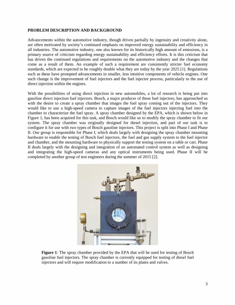
PROBLEM DESCRIPTION AND BACKGROUND Advancements within the automotive industry, though driven partially by ingenuity and creativity alone, are often motivated by society’s continued emphasis on improved energy sustainability and efficiency in all industries. The automotive industry, one also known for its historically high amount of emissions, is a primary source of criticism regarding energy sustainability and efficiency efforts. It is this criticism that has driven the continued regulations and requirements on the automotive industry and the changes that come as a result of them. An example of such a requirement are consistently stricter fuel economy standards, which are expected to be roughly double what they are today by the year 2025 [1]. Regulations such as these have prompted advancements in smaller, less intuitive components of vehicle engines. One such change is the improvement of fuel injectors and the fuel injector process, particularly to the use of direct injection within the engines. With the possibilities of using direct injection in new automobiles, a lot of research is being put into gasoline direct injection fuel injectors. Bosch, a major producer of these fuel injectors, has approached us with the desire to create a spray chamber that images the fuel spray coming out of the injectors. They would like to use a high-speed camera to capture images of the fuel injectors injecting fuel into the chamber to characterize the fuel spray. A spray chamber designed by the EPA, which is shown below in Figure 1, has been acquired for this task, and Bosch would like us to modify the spray chamber to fit our system. The spray chamber was originally designed for diesel injection, and part of our task is to configure it for use with two types of Bosch gasoline injectors. This project is split into Phase I and Phase II. Our group is responsible for Phase I, which deals largely with designing the spray chamber mounting hardware to enable the testing of Bosch fuel injectors, the fuel and gas supply system to the fuel injector and chamber, and the mounting hardware to physically support the testing system on a table or cart. Phase II deals largely with the designing and integration of an automated control system as well as designing and integrating the high-speed cameras and any optical instruments being used. Phase II will be completed by another group of test engineers during the summer of 2015 [2].
Figure 1: The spray chamber provided by the EPA that will be used for testing of Bosch gasoline fuel injectors. The spray chamber is currently equipped for testing of diesel fuel injectors and will require modification to a number of its plates and valves.
3
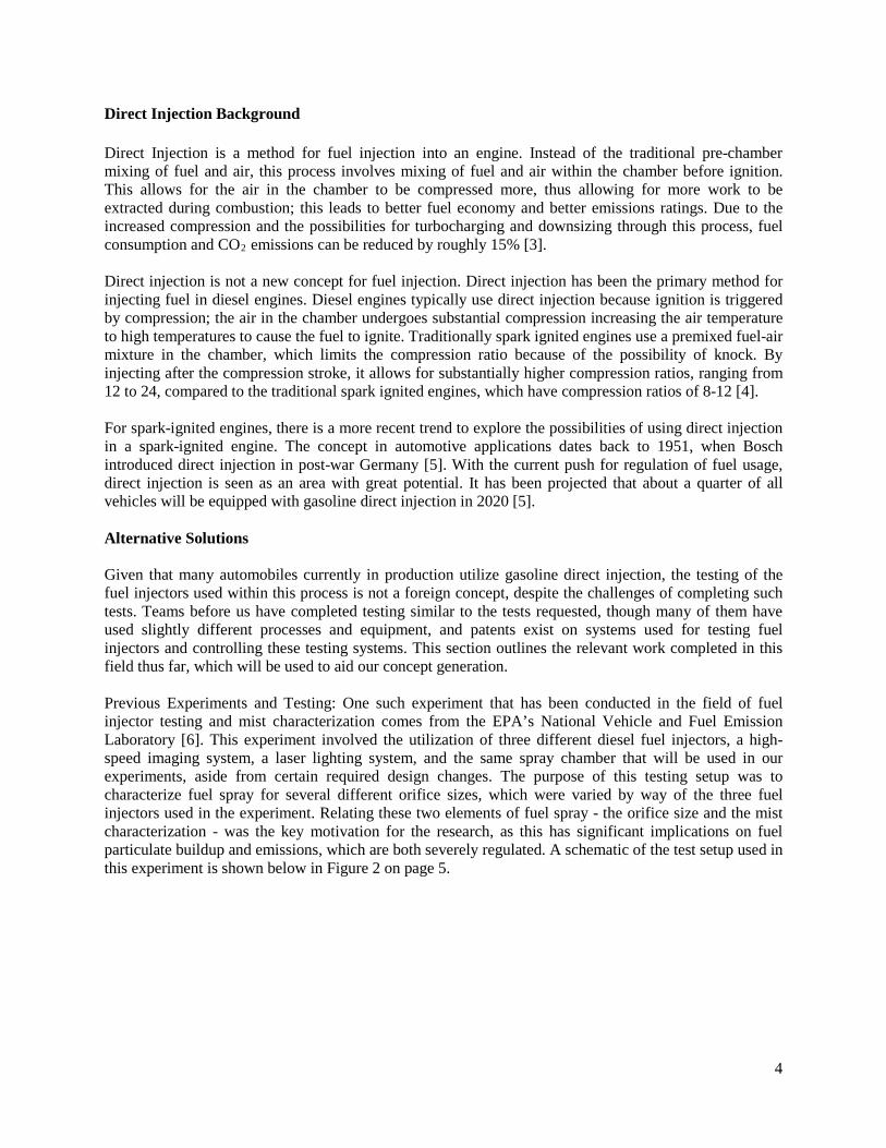
Direct Injection Background Direct Injection is a method for fuel injection into an engine. Instead of the traditional pre-chamber mixing of fuel and air, this process involves mixing of fuel and air within the chamber before ignition. This allows for the air in the chamber to be compressed more, thus allowing for more work to be extracted during combustion; this leads to better fuel economy and better emissions ratings. Due to the increased compression and the possibilities for turbocharging and downsizing through this process, fuel consumption and CO2 emissions can be reduced by roughly 15% [3]. Direct injection is not a new concept for fuel injection. Direct injection has been the primary method for injecting fuel in diesel engines. Diesel engines typically use direct injection because ignition is triggered by compression; the air in the chamber undergoes substantial compression increasing the air temperature to high temperatures to cause the fuel to ignite. Traditionally spark ignited engines use a premixed fuel-air mixture in the chamber, which limits the compression ratio because of the possibility of knock. By injecting after the compression stroke, it allows for substantially higher compression ratios, ranging from 12 to 24, compared to the traditional spark ignited engines, which have compression ratios of 8-12 [4]. For spark-ignited engines, there is a more recent trend to explore the possibilities of using direct injection in a spark-ignited engine. The concept in automotive applications dates back to 1951, when Bosch introduced direct injection in post-war Germany [5]. With the current push for regulation of fuel usage, direct injection is seen as an area with great potential. It has been projected that about a quarter of all vehicles will be equipped with gasoline direct injection in 2020 [5]. Alternative Solutions Given that many automobiles currently in production utilize gasoline direct injection, the testing of the fuel injectors used within this process is not a foreign concept, despite the challenges of completing such tests. Teams before us have completed testing similar to the tests requested, though many of them have used slightly different processes and equipment, and patents exist on systems used for testing fuel injectors and controlling these testing systems. This section outlines the relevant work completed in this field thus far, which will be used to aid our concept generation. Previous Experiments and Testing: One such experiment that has been conducted in the field of fuel injector testing and mist characterization comes from the EPA’s National Vehicle and Fuel Emission Laboratory [6]. This experiment involved the utilization of three different diesel fuel injectors, a high-speed imaging system, a laser lighting system, and the same spray chamber that will be used in our experiments, aside from certain required design changes. The purpose of this testing setup was to characterize fuel spray for several different orifice sizes, which were varied by way of the three fuel injectors used in the experiment. Relating these two elements of fuel spray - the orifice size and the mist characterization - was the key motivation for the research, as this has significant implications on fuel particulate buildup and emissions, which are both severely regulated. A schematic of the test setup used in this experiment is shown below in Figure 2 on page 5.
4
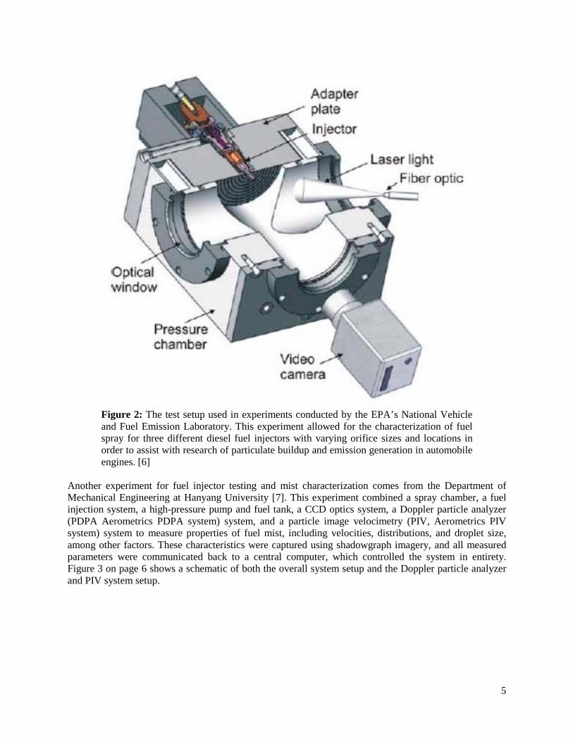
Figure 2: The test setup used in experiments conducted by the EPA’s National Vehicle and Fuel Emission Laboratory. This experiment allowed for the characterization of fuel spray for three different diesel fuel injectors with varying orifice sizes and locations in order to assist with research of particulate buildup and emission generation in automobile engines. [6]
Another experiment for fuel injector testing and mist characterization comes from the Department of Mechanical Engineering at Hanyang University [7]. This experiment combined a spray chamber, a fuel injection system, a high-pressure pump and fuel tank, a CCD optics system, a Doppler particle analyzer (PDPA Aerometrics PDPA system) system, and a particle image velocimetry (PIV, Aerometrics PIV system) system to measure properties of fuel mist, including velocities, distributions, and droplet size, among other factors. These characteristics were captured using shadowgraph imagery, and all measured parameters were communicated back to a central computer, which controlled the system in entirety. Figure 3 on page 6 shows a schematic of both the overall system setup and the Doppler particle analyzer and PIV system setup.
5
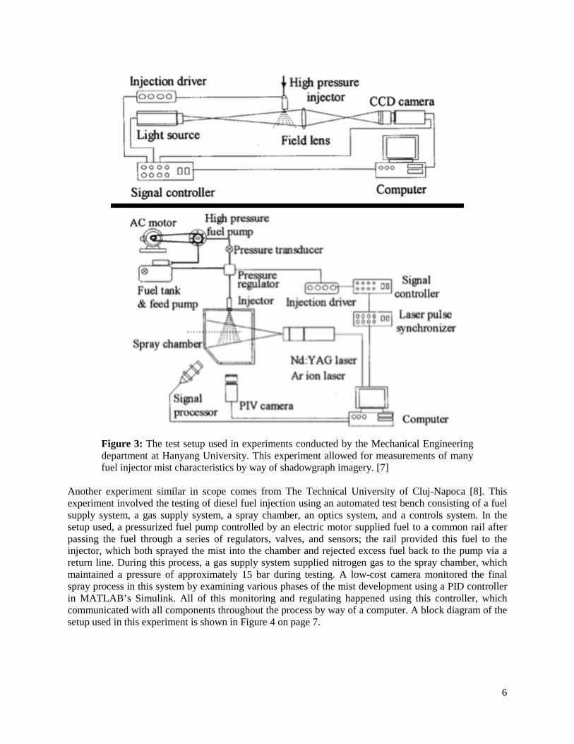
Figure 3: The test setup used in experiments conducted by the Mechanical Engineering department at Hanyang University. This experiment allowed for measurements of many fuel injector mist characteristics by way of shadowgraph imagery. [7]
Another experiment similar in scope comes from The Technical University of Cluj-Napoca [8]. This experiment involved the testing of diesel fuel injection using an automated test bench consisting of a fuel supply system, a gas supply system, a spray chamber, an optics system, and a controls system. In the setup used, a pressurized fuel pump controlled by an electric motor supplied fuel to a common rail after passing the fuel through a series of regulators, valves, and sensors; the rail provided this fuel to the injector, which both sprayed the mist into the chamber and rejected excess fuel back to the pump via a return line. During this process, a gas supply system supplied nitrogen gas to the spray chamber, which maintained a pressure of approximately 15 bar during testing. A low-cost camera monitored the final spray process in this system by examining various phases of the mist development using a PID controller in MATLAB’s Simulink. All of this monitoring and regulating happened using this controller, which communicated with all components throughout the process by way of a computer. A block diagram of the setup used in this experiment is shown in Figure 4 on page 7.
6
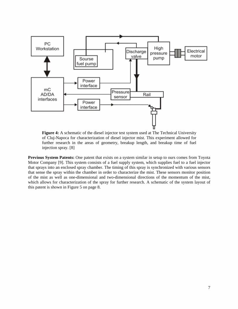
Figure 4: A schematic of the diesel injector test system used at The Technical University of Cluj-Napoca for characterization of diesel injector mist. This experiment allowed for further research in the areas of geometry, breakup length, and breakup time of fuel injection spray. [8]
Previous System Patents: One patent that exists on a system similar in setup to ours comes from Toyota Motor Company [9]. This system consists of a fuel supply system, which supplies fuel to a fuel injector that sprays into an enclosed spray chamber. The timing of this spray is synchronized with various sensors that sense the spray within the chamber in order to characterize the mist. These sensors monitor position of the mist as well as one-dimensional and two-dimensional directions of the momentum of the mist, which allows for characterization of the spray for further research. A schematic of the system layout of this patent is shown in Figure 5 on page 8.
7
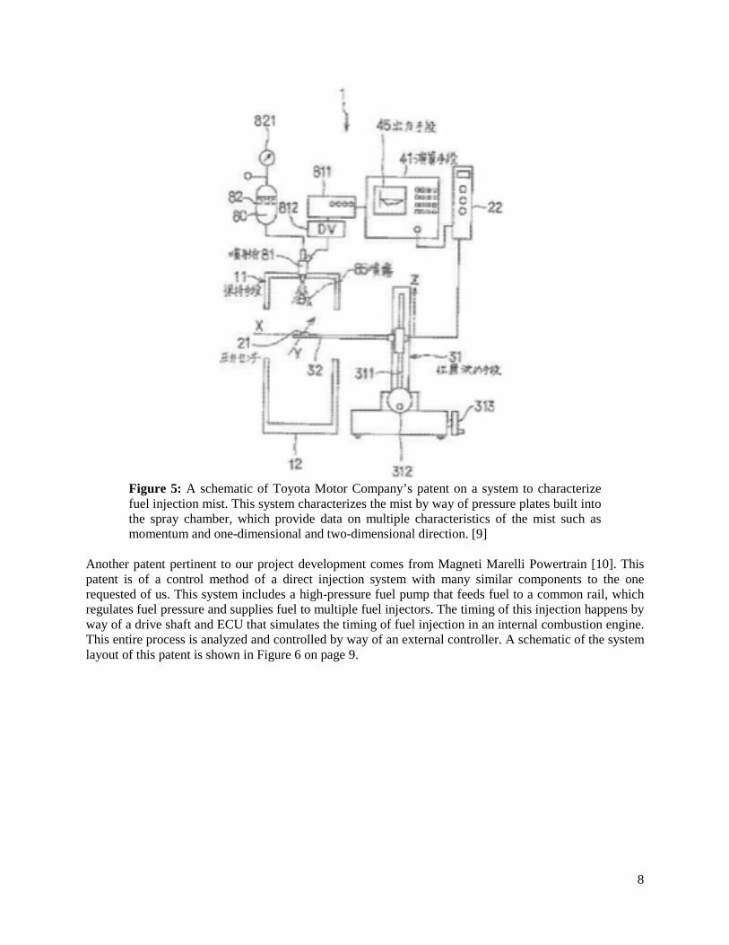
Figure 5: A schematic of Toyota Motor Company’s patent on a system to characterize fuel injection mist. This system characterizes the mist by way of pressure plates built into the spray chamber, which provide data on multiple characteristics of the mist such as momentum and one-dimensional and two-dimensional direction. [9]
Another patent pertinent to our project development comes from Magneti Marelli Powertrain [10]. This patent is of a control method of a direct injection system with many similar components to the one requested of us. This system includes a high-pressure fuel pump that feeds fuel to a common rail, which regulates fuel pressure and supplies fuel to multiple fuel injectors. The timing of this injection happens by way of a drive shaft and ECU that simulates the timing of fuel injection in an internal combustion engine. This entire process is analyzed and controlled by way of an external controller. A schematic of the system layout of this patent is shown in Figure 6 on page 9.
8
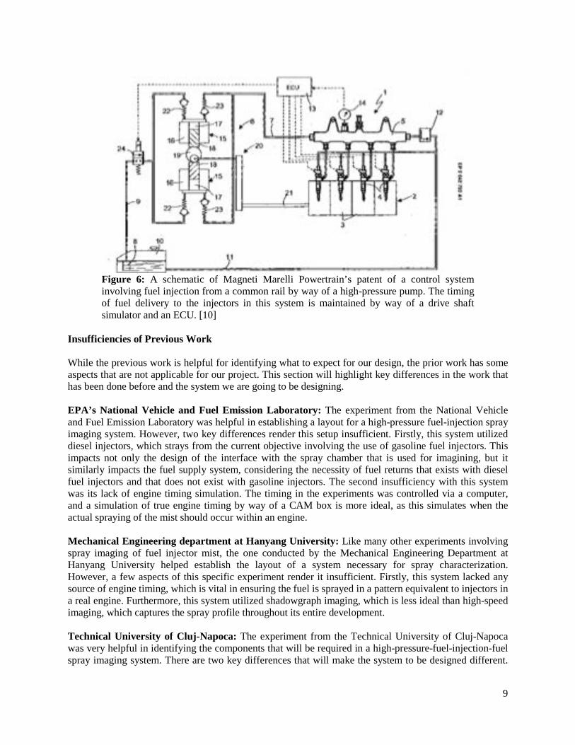
Figure 6: A schematic of Magneti Marelli Powertrain’s patent of a control system involving fuel injection from a common rail by way of a high-pressure pump. The timing of fuel delivery to the injectors in this system is maintained by way of a drive shaft simulator and an ECU. [10]
Insufficiencies of Previous Work While the previous work is helpful for identifying what to expect for our design, the prior work has some aspects that are not applicable for our project. This section will highlight key differences in the work that has been done before and the system we are going to be designing. EPA’s National Vehicle and Fuel Emission Laboratory: The experiment from the National Vehicle and Fuel Emission Laboratory was helpful in establishing a layout for a high-pressure fuel-injection spray imaging system. However, two key differences render this setup insufficient. Firstly, this system utilized diesel injectors, which strays from the current objective involving the use of gasoline fuel injectors. This impacts not only the design of the interface with the spray chamber that is used for imagining, but it similarly impacts the fuel supply system, considering the necessity of fuel returns that exists with diesel fuel injectors and that does not exist with gasoline injectors. The second insufficiency with this system was its lack of engine timing simulation. The timing in the experiments was controlled via a computer, and a simulation of true engine timing by way of a CAM box is more ideal, as this simulates when the actual spraying of the mist should occur within an engine. Mechanical Engineering department at Hanyang University: Like many other experiments involving spray imaging of fuel injector mist, the one conducted by the Mechanical Engineering Department at Hanyang University helped establish the layout of a system necessary for spray characterization. However, a few aspects of this specific experiment render it insufficient. Firstly, this system lacked any source of engine timing, which is vital in ensuring the fuel is sprayed in a pattern equivalent to injectors in a real engine. Furthermore, this system utilized shadowgraph imaging, which is less ideal than high-speed imaging, which captures the spray profile throughout its entire development. Technical University of Cluj-Napoca: The experiment from the Technical University of Cluj-Napoca was very helpful in identifying the components that will be required in a high-pressure-fuel-injection-fuel spray imaging system. There are two key differences that will make the system to be designed different.
9
The first is that the Technical University of Cluj-Napoca’s experiment was designed to use diesel fuel. This required that their fuel injectors have fuel return systems as well as being able to operate at a lower chamber pressure. Since our system will use gasoline based fuels, the chamber pressure will need to be at a higher pressure, but there will be no fuel return for our injectors. The second difference was that the system was designed to utilize phase imaging. Our system will utilize a high-speed camera so that a progression can be generated from spray, thus allowing for a more reliable result. Toyota Patent: The Toyota patent was a patent on a system that we found to be very similar in objective to what our system will need to accomplish. This system utilizes sensors to characterize the spray from a direct injection fuel injector. There should be no problems in copyright infringement in regards to this previous project because their system uses a variety of pressure and position sensors within the chamber to characterize the spray whereas we will utilize a high-speed camera to capture images of the spray. Magneti Marelli Powertrain Patent: The patent submitted by the Magneti Marelli Powertrain group is a useful system that demonstrates the control method for controlling high-pressure fuel injection. This method will be more directly helpful for phase 2 of this project, however it is helpful in demonstrating the required components for effective control of this kind of system. This system is a little bit beyond the scope of this project as the control system is used for multiple fuel injectors along a rail, whereas for this project will only integrate one fuel injector. This patent is also limited to only the fuel injection aspect of the system whereas our controls system will also need to regulate the chamber pressure and timing of actuation of the imaging system. USER REQUIREMENTS AND ENGINEERING SPECIFICATIONS Based on the project description, the project plan, specific needs expressed by Michael Mosburger and Thomas Stach of Bosch and Professor André Boehman during a preliminary design meeting, and independent discussions on the implementation of components, we have collected a list of user requirements, shown in Table 1 on page 11. From these requirements we have generated a list of engineering specifications that will satisfy these requirements independent of design, and Figure 7 on page 12 shows a systems diagram of the main required components. This section outlines and describes the user requirements, the corresponding specification, and the rationale for the specifications.
10
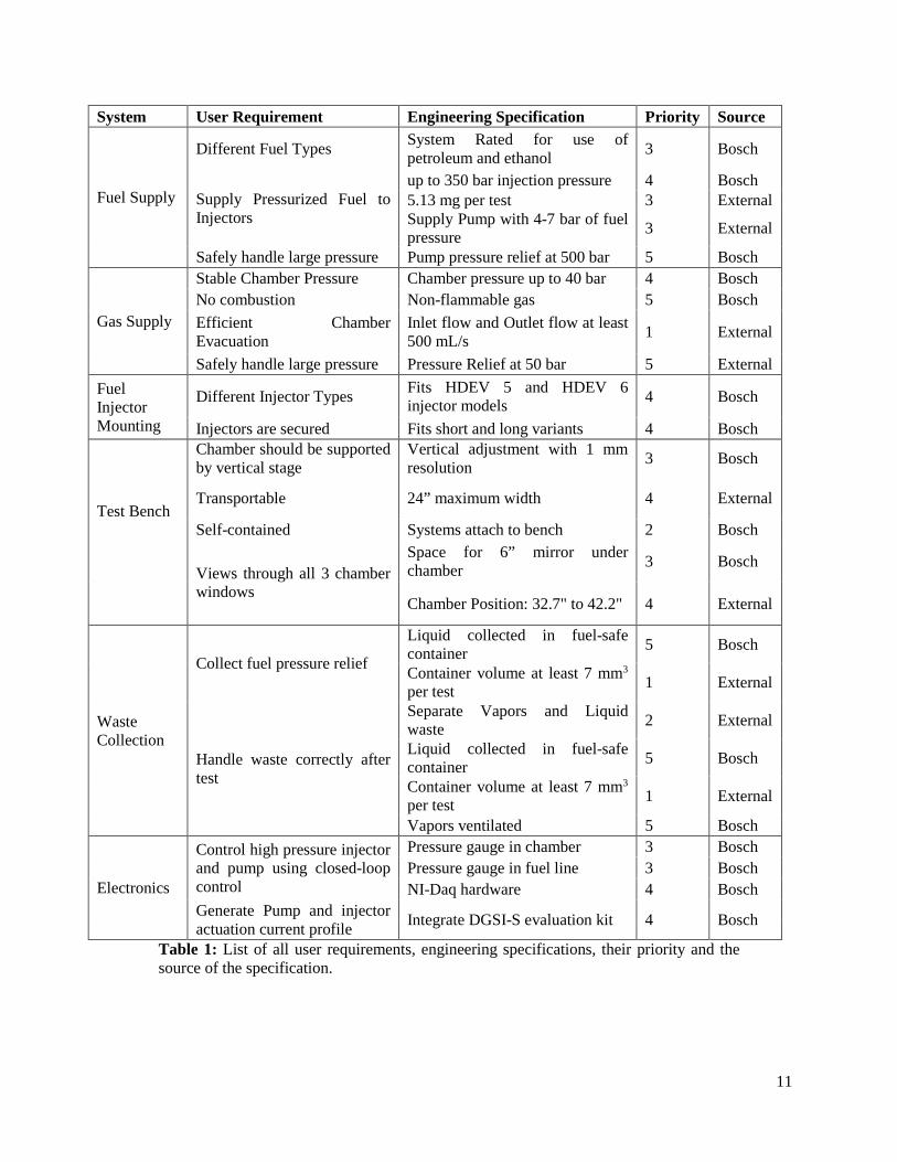
System User Requirement Engineering Specification Priority Source
Fuel Supply
Different Fuel Types System Rated for use of petroleum and ethanol 3 Bosch
Supply Pressurized Fuel to Injectors
up to 350 bar injection pressure 4 Bosch 5.13 mg per test 3 External Supply Pump with 4-7 bar of fuel pressure 3 External
Safely handle large pressure Pump pressure relief at 500 bar 5 Bosch
Gas Supply
Stable Chamber Pressure Chamber pressure up to 40 bar 4 Bosch No combustion Non-flammable gas 5 Bosch Efficient Chamber Evacuation
Inlet flow and Outlet flow at least 500 mL/s 1 External
Safely handle large pressure Pressure Relief at 50 bar 5 External Fuel Injector Mounting
Different Injector Types Fits HDEV 5 and HDEV 6 injector models 4 Bosch
Injectors are secured Fits short and long variants 4 Bosch
Test Bench
Chamber should be supported by vertical stage
Vertical adjustment with 1 mm resolution 3 Bosch
Transportable 24” maximum width 4 External
Self-contained Systems attach to bench 2 Bosch
Views through all 3 chamber windows
Space for 6” mirror under chamber 3 Bosch
Chamber Position: 32.7" to 42.2" 4 External
Waste Collection
Collect fuel pressure relief
Liquid collected in fuel-safe container 5 Bosch
Container volume at least 7 mm3 per test 1 External
Handle waste correctly after test
Separate Vapors and Liquid waste 2 External
Liquid collected in fuel-safe container 5 Bosch
Container volume at least 7 mm3 per test 1 External
Vapors ventilated 5 Bosch
Electronics
Control high pressure injector and pump using closed-loop control
Pressure gauge in chamber 3 Bosch Pressure gauge in fuel line 3 Bosch NI-Daq hardware 4 Bosch
Generate Pump and injector actuation current profile Integrate DGSI-S evaluation kit 4 Bosch
Table 1: List of all user requirements, engineering specifications, their priority and the source of the specification.
11
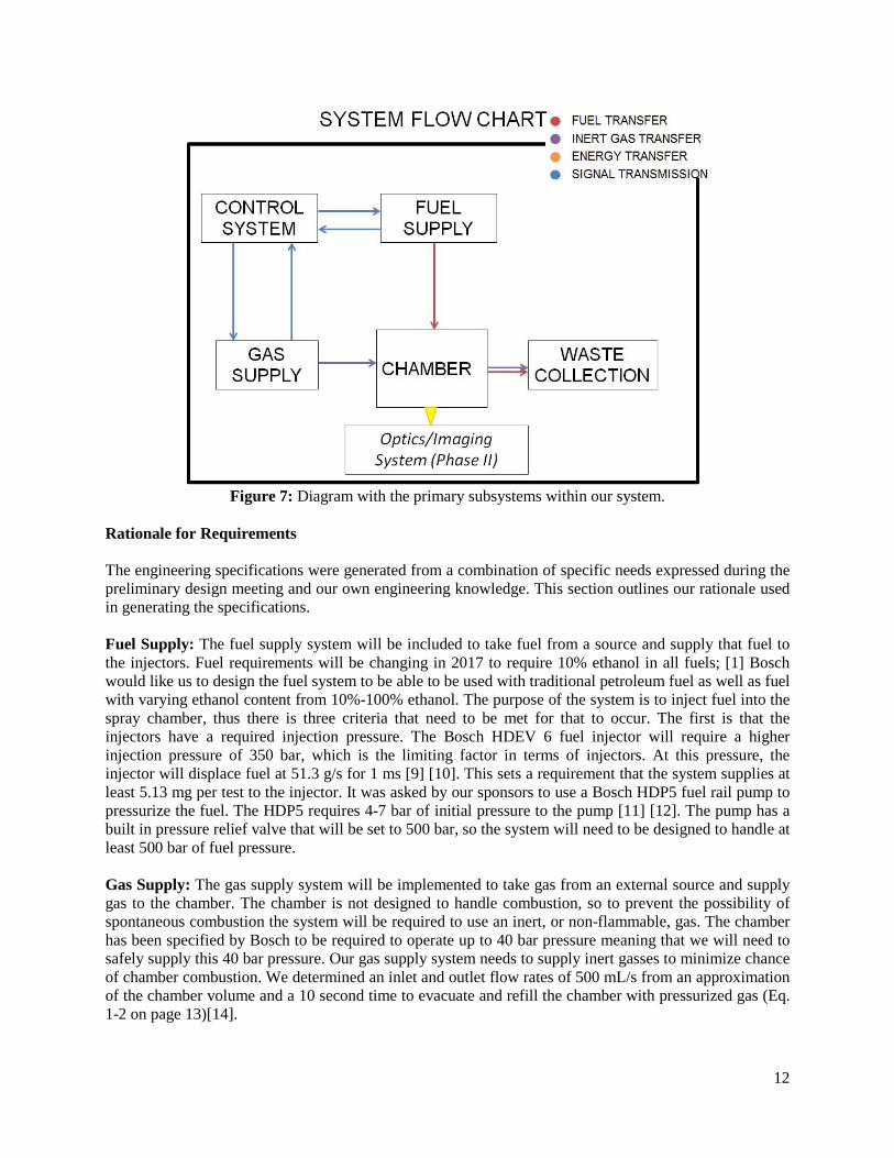
Figure 7: Diagram with the primary subsystems within our system.
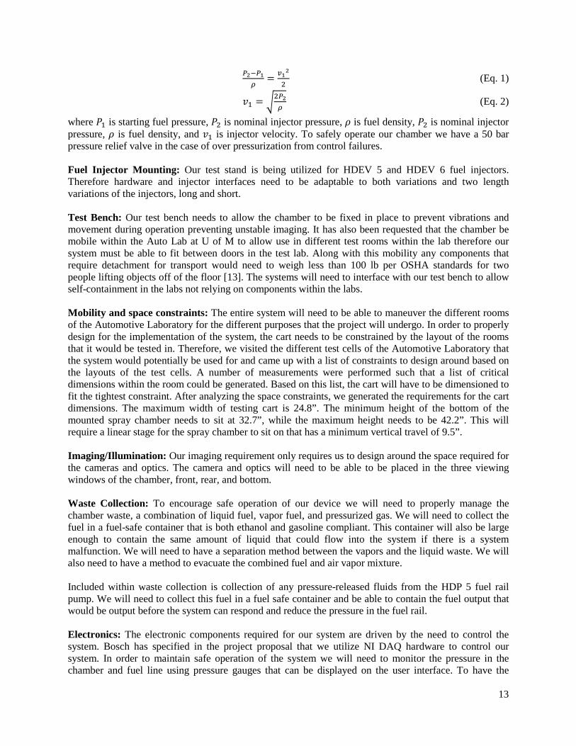
Rationale for Requirements The engineering specifications were generated from a combination of specific needs expressed during the preliminary design meeting and our own engineering knowledge. This section outlines our rationale used in generating the specifications. Fuel Supply: The fuel supply system will be included to take fuel from a source and supply that fuel to the injectors. Fuel requirements will be changing in 2017 to require 10% ethanol in all fuels; [1] Bosch would like us to design the fuel system to be able to be used with traditional petroleum fuel as well as fuel with varying ethanol content from 10%-100% ethanol. The purpose of the system is to inject fuel into the spray chamber, thus there is three criteria that need to be met for that to occur. The first is that the injectors have a required injection pressure. The Bosch HDEV 6 fuel injector will require a higher injection pressure of 350 bar, which is the limiting factor in terms of injectors. At this pressure, the injector will displace fuel at 51.3 g/s for 1 ms [9] [10]. This sets a requirement that the system supplies at least 5.13 mg per test to the injector. It was asked by our sponsors to use a Bosch HDP5 fuel rail pump to pressurize the fuel. The HDP5 requires 4-7 bar of initial pressure to the pump [11] [12]. The pump has a built in pressure relief valve that will be set to 500 bar, so the system will need to be designed to handle at least 500 bar of fuel pressure. Gas Supply: The gas supply system will be implemented to take gas from an external source and supply gas to the chamber. The chamber is not designed to handle combustion, so to prevent the possibility of spontaneous combustion the system will be required to use an inert, or non-flammable, gas. The chamber has been specified by Bosch to be required to operate up to 40 bar pressure meaning that we will need to safely supply this 40 bar pressure. Our gas supply system needs to supply inert gasses to minimize chance of chamber combustion. We determined an inlet and outlet flow rates of 500 mL/s from an approximation of the chamber volume and a 10 second time to evacuate and refill the chamber with pressurized gas (Eq. 1-2 on page 13)[14].
12
𝑃𝑃2−𝑃𝑃1𝜌𝜌
= 𝑣𝑣12
2 (Eq. 1)
𝑣𝑣1 = �2𝑃𝑃2𝜌𝜌
(Eq. 2)
where 𝑃𝑃1 is starting fuel pressure, 𝑃𝑃2 is nominal injector pressure, 𝜌𝜌 is fuel density, 𝑃𝑃2 is nominal injector pressure, 𝜌𝜌 is fuel density, and 𝑣𝑣1 is injector velocity. To safely operate our chamber we have a 50 bar pressure relief valve in the case of over pressurization from control failures. Fuel Injector Mounting: Our test stand is being utilized for HDEV 5 and HDEV 6 fuel injectors. Therefore hardware and injector interfaces need to be adaptable to both variations and two length variations of the injectors, long and short. Test Bench: Our test bench needs to allow the chamber to be fixed in place to prevent vibrations and movement during operation preventing unstable imaging. It has also been requested that the chamber be mobile within the Auto Lab at U of M to allow use in different test rooms within the lab therefore our system must be able to fit between doors in the test lab. Along with this mobility any components that require detachment for transport would need to weigh less than 100 lb per OSHA standards for two people lifting objects off of the floor [13]. The systems will need to interface with our test bench to allow self-containment in the labs not relying on components within the labs. Mobility and space constraints: The entire system will need to be able to maneuver the different rooms of the Automotive Laboratory for the different purposes that the project will undergo. In order to properly design for the implementation of the system, the cart needs to be constrained by the layout of the rooms that it would be tested in. Therefore, we visited the different test cells of the Automotive Laboratory that the system would potentially be used for and came up with a list of constraints to design around based on the layouts of the test cells. A number of measurements were performed such that a list of critical dimensions within the room could be generated. Based on this list, the cart will have to be dimensioned to fit the tightest constraint. After analyzing the space constraints, we generated the requirements for the cart dimensions. The maximum width of testing cart is 24.8”. The minimum height of the bottom of the mounted spray chamber needs to sit at 32.7”, while the maximum height needs to be 42.2”. This will require a linear stage for the spray chamber to sit on that has a minimum vertical travel of 9.5”. Imaging/Illumination: Our imaging requirement only requires us to design around the space required for the cameras and optics. The camera and optics will need to be able to be placed in the three viewing windows of the chamber, front, rear, and bottom. Waste Collection: To encourage safe operation of our device we will need to properly manage the chamber waste, a combination of liquid fuel, vapor fuel, and pressurized gas. We will need to collect the fuel in a fuel-safe container that is both ethanol and gasoline compliant. This container will also be large enough to contain the same amount of liquid that could flow into the system if there is a system malfunction. We will need to have a separation method between the vapors and the liquid waste. We will also need to have a method to evacuate the combined fuel and air vapor mixture. Included within waste collection is collection of any pressure-released fluids from the HDP 5 fuel rail pump. We will need to collect this fuel in a fuel safe container and be able to contain the fuel output that would be output before the system can respond and reduce the pressure in the fuel rail. Electronics: The electronic components required for our system are driven by the need to control the system. Bosch has specified in the project proposal that we utilize NI DAQ hardware to control our system. In order to maintain safe operation of the system we will need to monitor the pressure in the chamber and fuel line using pressure gauges that can be displayed on the user interface. To have the
13
functionality of the system we will need to use a DGDSI-S evaluation kit to provide the current profiles required by both the fuel injector and fuel rail pump. CONCEPT GENERATION After generating our list of engineering specifications, we then moved to generating concepts and selecting a concept that would be able to satisfy all the requirements. This section highlights the categories of concepts generated, the methods by which concepts were generated, and the method used to compare the concepts. Concept Categories In order to come up with clear, concise concepts we decided to generate concepts in sub categories that completed specific functions. We would then be able to take these specific concepts and then compile the different concepts to come up with entire system concepts. The subcategories for concepts were: fuel supply, inert gas exchange, waste collection, transportation method, cart frame, and injector mounting. The fuel supply concept must be able to supply pressurized fuel to the injectors through the HDP5 pump. The inert gas exchange concept needs to be able to supply an inert gas, of our choosing, to the spray chamber at a controlled pressure. After a test is done, the fuel-inert gas mix will need to be handled properly through a waste collection system. In terms of cart/frame design, the system needs to be able to be moved from room-to-room with relative ease, and the system should be contained on the test bench. Finally, the injectors need to be securely mounted to the chamber, and the securement method needs to be able to incorporate use with different models of injectors. Concept Generation Methods We used a few methods to generate concepts to comply with our engineering specifications. We first came up with a functional decomposition of our system based on the specifications and components that were either generated or required by our sponsors. This helped identify the needs for our concepts. We then came up with our own concepts and came together and did some brainstorming. The brainstorming was particularly useful for the fuel and inert gas exchange systems because those concepts are component based systems and brainstorming allowed for us to come up with different components to integrate into those systems. We also used some design cards to supplement our concept generation. The cards would present different components as inputs, outputs, ways to connect components, and ways to supply power. The cards gave us options for generating ideas by presenting different components that could be used to meet our specifications. Concepts Generated Using our concept generation methods and guidelines, we came up with a number of concepts that will fulfill our user requirements and satisfy our engineering specifications. This section will dissect some of the unique concepts. All the generated concepts can be found in Appendix A. Fuel Supply: The concepts generated for a fuel supply system were lists and layouts of components. All of our concepts had the components provided by Bosch and recommended components, which are as follows: spray chamber, HDEV 5 and HDEV 6 fuel injectors, HDP5 high pressure pump, cam-box to mechanically drive HDP5 pump, and pressure gauges and valves to control flow in the system.
14
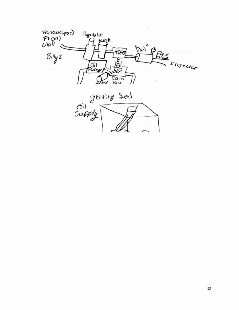
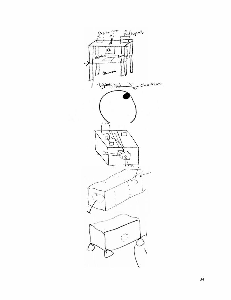
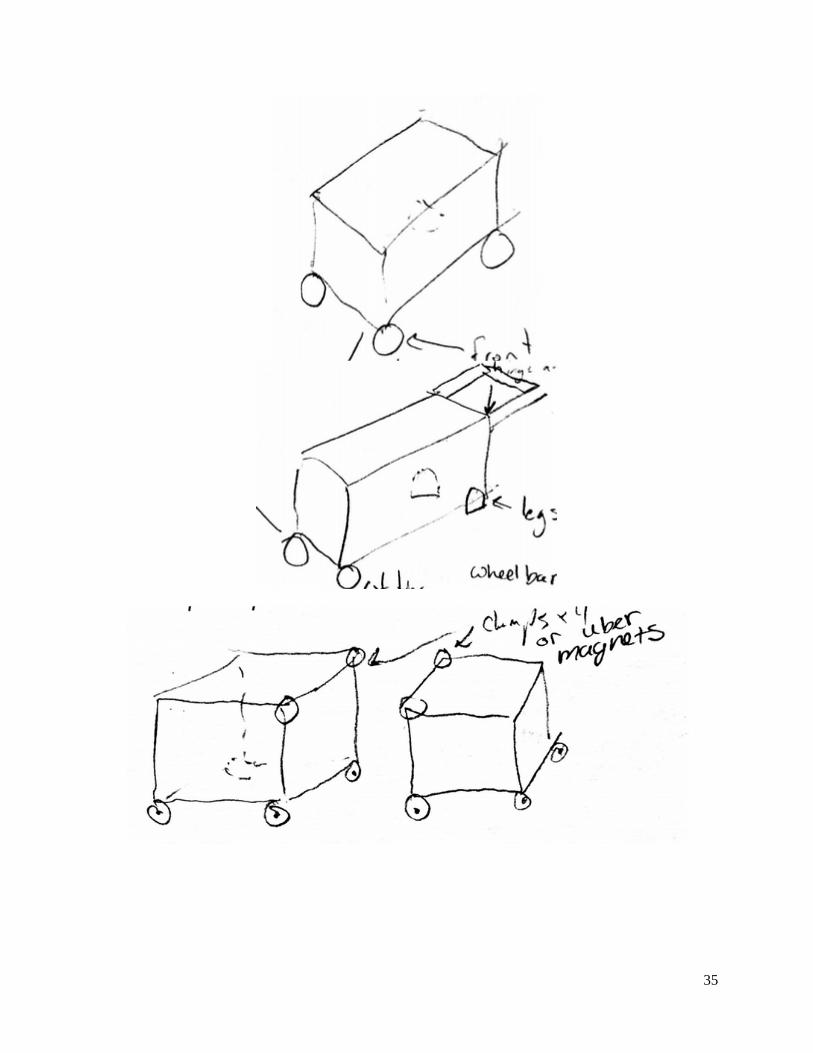
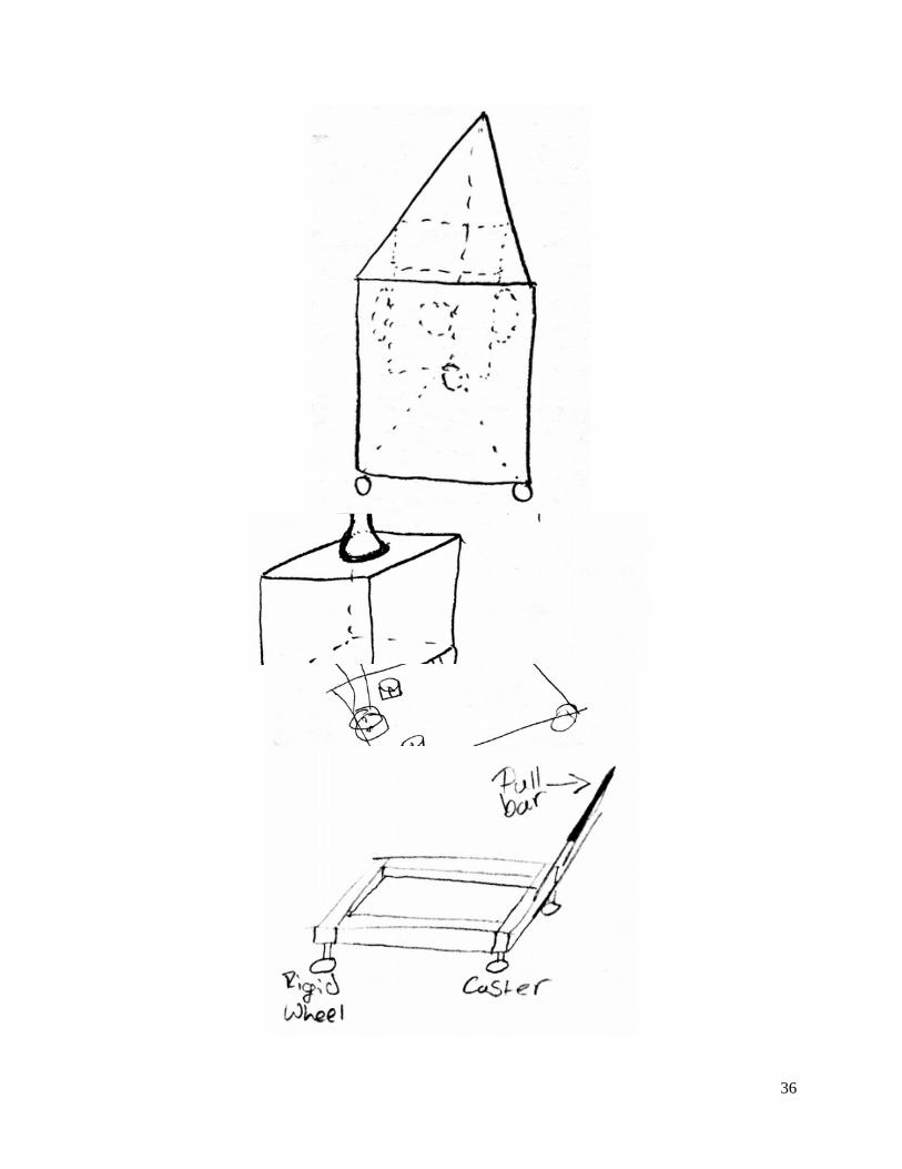
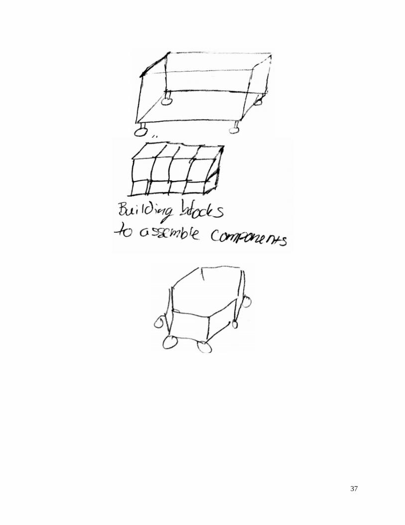
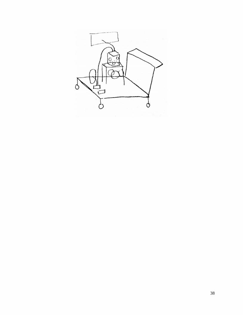
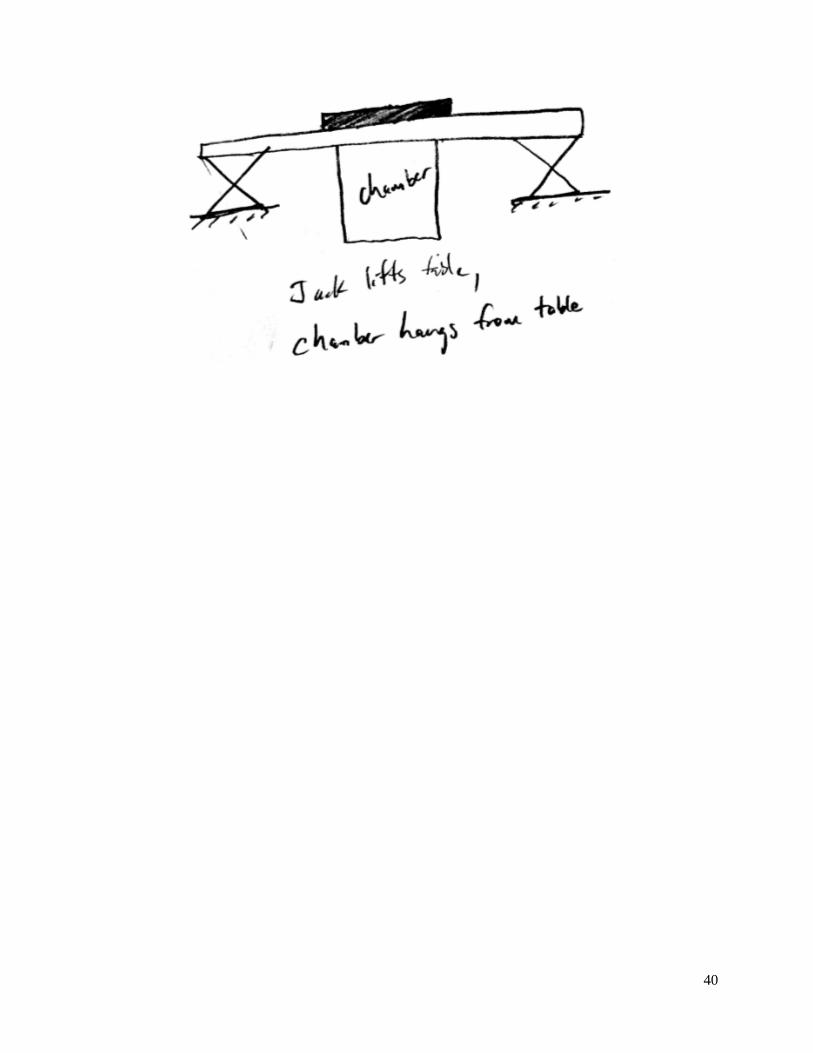
There were two main differences in the components list: the method by which fuel is stored in the system, and supplying oil to the cam box. The consensus for storing fuel in our system was either to have an internal storage container that gets refilled periodically for testing, or drawing fuel from an external supply. If there is standing fuel in the system, a separate pump would have to pump the fuel from the storage container to 4-7 bar so that the HDP5 pump would be able to operate properly. In regards to the cam box, three ideas stood out. The first is a gravity fed system; oil is held in a reservoir above the cam box and gravity forces the oil to circulate through the box. Another concept uses an oil pump that will circulate through the system. In the last concept the oil is changed out manually after a specified number of tests. Inert Gas Exchange: The concepts generated for the inert gas system again were a list of components, but also included what gas would be supplied. Each concept included similar components: spray chamber, compressor, and pressure gauges and valves to control flow through the system. One area of concepts was the inert gas that was supplied to the chamber. Researching a list of inert gases gave us 6 gases. From a meeting with our customer, the gases that are readily available are argon, carbon dioxide, helium, and nitrogen. In regards to components that could be implemented, our two differences in concepts were in regards to the method for storing the gas and how the waste would be processed. For storage, one concept would be to have a tank built into the cart to hold the gas, with the alternative being to extract from an external supply. One of the concepts for waste processing was an open container that all the fuel and gas would flow into after the test, and the liquid fuel would collect in the bottom of the container, and all vapors would evacuate through the top of the container and be removed through a ventilation system. Another concept uses a fuel filter that would filter any fuel vapor from the gas and then release the gas only. The liquid fuel would also collect at the bottom of the container to be disposed of safely. Cart/Frame: The concepts generated for the cart/frame were the most diverse. The first aspect that was addressed was the ability for the system to be transported from room-to-room within the Automotive Laboratory. Also the entire system would be contained by this concept, so different shapes and organizational methods were considered. Part of this containment is a mount that would be designed to support the chamber. A specific requirement that the Cart/Frame system would address is the transportability of the system. The concepts that were generated fall into three main categories: a self-contained system that could be put on wheels, a system that was compiled of a few parts that were disassembled and the reassembled in another room, or a hybrid of both. For the wheel designs there were a variety of options involving casters, rigid wheels, or Omni-wheels. The concepts also used a variety of shapes and organizations to the Cart/Frame system. The most popular shape was a rectangular box, with possibly three shelf layers. Another concept involved the system sitting on a cart that would sit low to the ground with a handle extending to waist height. This concept is favorable to implement a pyramid organization for the other systems. The concepts for securing the chamber to the Cart/Frame were grouped into either top plate support or bottom support. The top plate of the spray chamber will need to be redesigned for implementing the Bosch injectors, so a variety of concepts involved utilizing that plate to support the chamber. One of these concepts that was unique involved tabs that extended from the top plate that could be then used to attach to a rail or table that would hold the other systems.
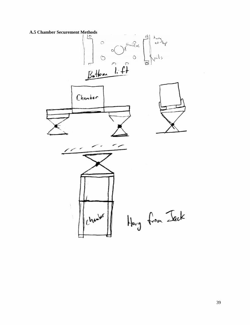
15
The concepts for securing the chamber to the Cart/Frame were grouped into either top plate support or bottom support. The top plate of the spray chamber will need to be redesigned for implementing the Bosch injectors, so a variety of concepts involved utilizing that plate to support the chamber. One of these concepts that was unique involved tabs that extended from the top plate that could be used to attach to a rail or table that would hold the other systems. For bottom support, a jack would attach somehow to the bottom of the chamber and lift it up and down. One concept combined the two; the chamber would hang from a table and the jacks would lift the table. Injector Mounting: The injector mounting system is the most design-intensive area of our project. It was challenging to work within limited space and still apply proper securement. They also had to be applicable to both injector models and their short and long variants. The concepts had a variety of methods to apply downward pressure to the injector. One of the concepts used clips that are manufactured for use with the injectors in engine applications. Another concept implement supports that utilized space outside of the injector area and then extend to push down on the injector. In terms of ensuring securement, all the concepts integrate a machined reverse profile of the injector either into the plate or into an adaptor ring that would be swapped out for different injectors. Concept Selection Method Once we had generated all the concepts, we had to compare different concepts and choose the concepts on which we would base our design off of. This was done primarily with Pugh charts; some concepts were not considered once we acquired more information on the system. Based on our engineering specifications, the expressed needs and opinions of our sponsors and customers from our preliminary design meetings, and our own engineering knowledge we came up with the criteria to judge the different designs, their importance, and how the designs would be rated. The completed Pugh Charts can be found in Appendix B. The criteria we used to rate the concepts, in order of their importance were: performance, safety, manufacturability, maintenance or durability, integration, and cost. Performance and safety were weighted the same because we believed that the two most important factors were that the system met our requirements and that it would do so safely. Next was manufacturability because any system that we design needs to be able to be made by us using the resources available to us. After manufacturability, the lifetime of the concept was considered in terms of durability or the ability for the concept to be maintained. Finally integration and cost were the lowest valued criteria. By integration we mean the ability for the concept to fit into the entire system, especially the interfacing and space considerations. In our conversations with our sponsors and customers in regards to cost, the price of the system was not of utmost importance, but we thought it should be something to consider especially in a tiebreaker role. CHOSEN DESIGN Once the concept selection method was developed, we evaluated the concepts and examined the feasibility of the preferred concept. The concepts that were ranked the highest in their respective Pugh charts were found to be the preferred concept for each of the designated systems, and these concepts were the focal point of our chosen design. This design includes each of our specific subsystems, specifically the fuel supply system, the inert gas exchange system, the controls system, the cart/frame system, and the injector mounting system. Descriptions of each of these subsystems and their accompanying components are detailed below.
16
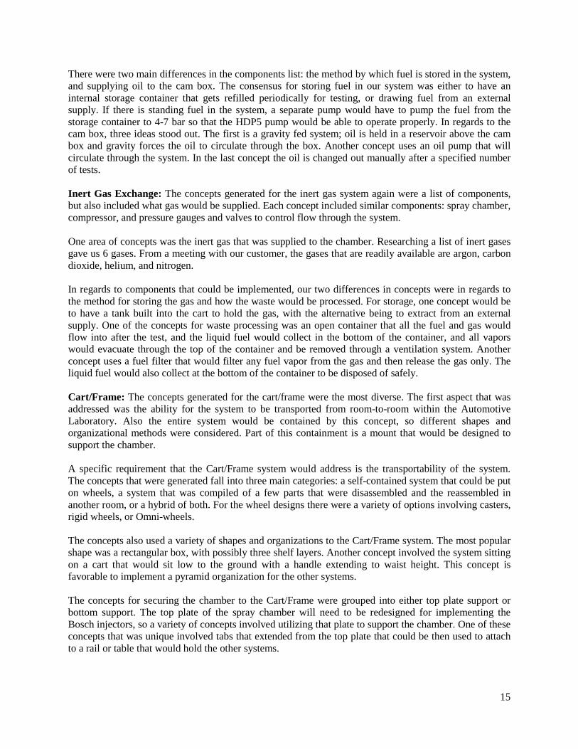
Fuel Supply System A list of components and their interactions were generated for the fuel supply system. Based on a customer recommendation, there will be a standing capacity of fuel used by our system; a schematic detailing the organization of the components can be seen below in Figure 8. From this standing capacity, a pump will pump the fuel to 4-7 bar that will feed the HDP5 pump. The HDP5 pump will then pump pressurized fuel to the injector. Near the injector there will be a bleed off valve for system purging purposes as well as any pressure relief build up. This bleed-off fuel will be collected also with the excess fuel. After an injection cycle fuel will be filtered and the liquid fuel will be collected in a fuel-safe container.
Figure 8: A schematic of the organization and interaction of components within the fuel subsystem.
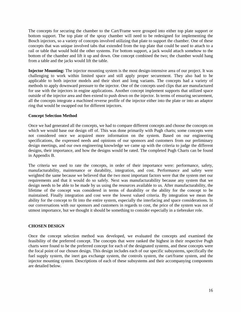
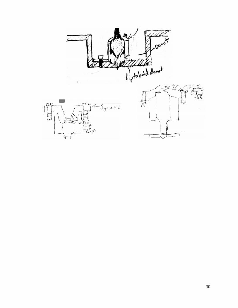
The major components within the system above, in addition to their corresponding numbers in the diagram above and in the Bill of Materials in Appendix C, are detailed below. The fuel storage we selected is a 1-gallon aluminum fuel cell (19), and the lift pump selected is a Magnafuel lift pump to increase the pressure from atmospheric (23). Furthermore, the pressure relief valve selected is an adjustable pressure relief valve (38) that will function at both the lower pressure of the HDEV 5 as well as the higher pressure HDEV 6. A list of these components and their connecting hoses is listed in the Bill of Materials in Appendix C. Inert Gas Exchange A list of components and their interactions was generated for the inert gas exchange system. A schematic detailing the organization of the components can be seen in Figure 9 on page 18. Based on a customer recommendation we will use Nitrogen to fill the chamber. The inert gas will be supplied by pressurized cylinders located in the room and then go through a compressor to increase the pressure of the gas. A valve will be used to control the flow of nitrogen into the chamber for testing. After a test has been
17
completed, the chamber will be evacuated again through a valve and go through a filter that will separate the vapors from the liquid fuel. The vapors will then be removed through a fume hood.
Figure 9: A schematic of the organization and interaction of components within the gas exchange subsystem.
The major component within the system above, in addition to its corresponding number in the diagram above and in the Bill of Materials in Appendix C, is detailed below. The pressure booster we selected is a McMaster booster lifting the tank pressure to at least the required chamber testing pressure (56). This component can be found in more detail in Appendix C. Controls System The major components within the system in Figure 10 on page 19, in addition to their corresponding numbers in the diagram above and in the Bill of Materials in Appendix C, are detailed below. The control system will be driven by NI-DAQ 4 card chassis (11). This will interface with the pressure sensors (58), rotational position sensor (1), solenoids (57), lift pump (23), and cam box motor (1). The pressure sensors selected are a 4-30 mA DC output with a precision of ±0.2% of capacity as well as Bosch supplied 0-5 V DC output, and the solenoids selected are driven by 24 VDC digital signals and are normally closed. We will use a freescale EV kit (1) to control the fuel rail pump and the injectors. A list of these components and required modules are listed in the Bill of Materials in Appendix C.
18
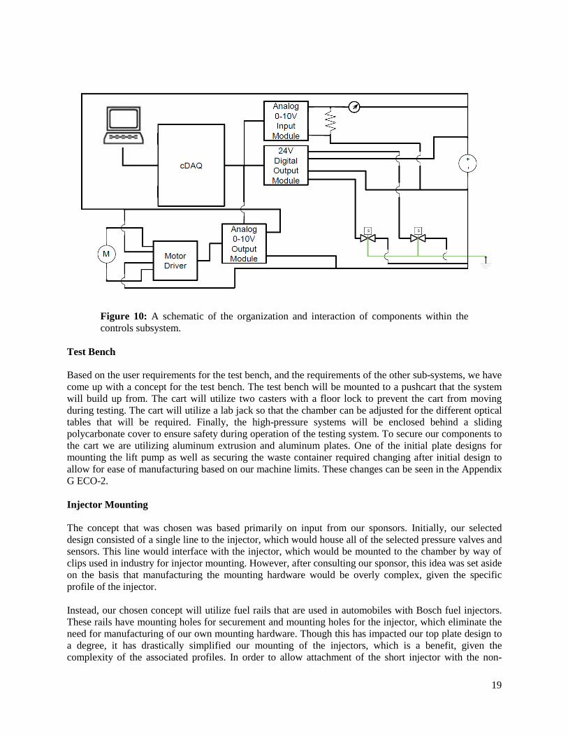
Figure 10: A schematic of the organization and interaction of components within the controls subsystem.
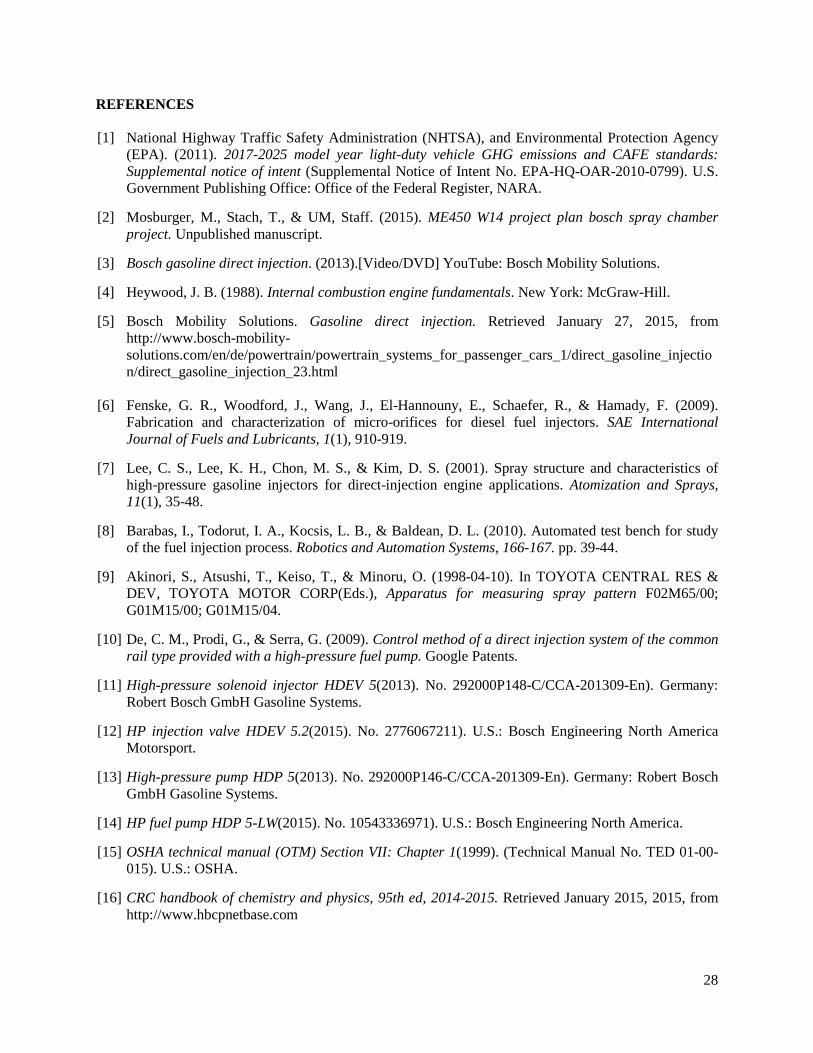
Test Bench Based on the user requirements for the test bench, and the requirements of the other sub-systems, we have come up with a concept for the test bench. The test bench will be mounted to a pushcart that the system will build up from. The cart will utilize two casters with a floor lock to prevent the cart from moving during testing. The cart will utilize a lab jack so that the chamber can be adjusted for the different optical tables that will be required. Finally, the high-pressure systems will be enclosed behind a sliding polycarbonate cover to ensure safety during operation of the testing system. To secure our components to the cart we are utilizing aluminum extrusion and aluminum plates. One of the initial plate designs for mounting the lift pump as well as securing the waste container required changing after initial design to allow for ease of manufacturing based on our machine limits. These changes can be seen in the Appendix G ECO-2. Injector Mounting The concept that was chosen was based primarily on input from our sponsors. Initially, our selected design consisted of a single line to the injector, which would house all of the selected pressure valves and sensors. This line would interface with the injector, which would be mounted to the chamber by way of clips used in industry for injector mounting. However, after consulting our sponsor, this idea was set aside on the basis that manufacturing the mounting hardware would be overly complex, given the specific profile of the injector. Instead, our chosen concept will utilize fuel rails that are used in automobiles with Bosch fuel injectors. These rails have mounting holes for securement and mounting holes for the injector, which eliminate the need for manufacturing of our own mounting hardware. Though this has impacted our top plate design to a degree, it has drastically simplified our mounting of the injectors, which is a benefit, given the complexity of the associated profiles. In order to allow attachment of the short injector with the non-
19
suspended fitting we are required to change the thickness of the injector plate as well as change the size of the center hole allowing us to utilized the factory mounting locations on the fuel rail without compromising structural integrity of the plate; this change can be seen in Appendix G ECO-1. We then changed the mounting hole threads for the fuel rails based on new hole dimensions on the injectors as well as bolt availability; this change can be seen in Appendix G ECO-3. DESIGN DRIVERS AND ENGINEERING ANALYSIS In establishing our chosen design, two engineering fundamentals critical to the design drove our conceptualization, modeling, and component selection. The functionality of the testing system and safety of the system are the main priorities of our project. The first of these design drivers, functionality, encompasses adequate fuel supply, adequate inert gas supply, proper material selection and sufficient material strength, and adequate system controls. Safety, the second design driver, is self-encompassing and ensures reduced risks when considered. These two design drivers necessitated a particular form of engineering analysis to ensure our fulfillment of system requirements, and these analyses for the various design drivers are outlined in the following sections and in full detail in Appendix D. Adequate Fuel Supply In designing the HDEV 5 and HDEV 6 fuel injectors, Bosch has given a nominal operating conditions that their injectors are rated to work at. Based on these conditions, our system will need to have the capabilities to supply the fuel to the injectors at their nominal operating conditions. Therefore, an analysis was performed on the volume requirements for the fuel supply. Based on the principle of conservation of mass, and assuming that the fuel is incompressible flowing out of the HDP5 at the desired pressure, then the volume that will flow to the injector can be defined as:
𝑉𝑉𝑖𝑖𝑖𝑖𝑖𝑖𝑖𝑖𝑖𝑖𝑖𝑖 = 𝑄𝑄𝑣𝑣 ∗ 𝑡𝑡𝑖𝑖𝑖𝑖𝑖𝑖𝑖𝑖𝑖𝑖𝑖𝑖 (Eq. 3) where 𝑉𝑉𝑖𝑖𝑖𝑖𝑖𝑖𝑖𝑖𝑖𝑖𝑖𝑖 is the volume used in one injection event, 𝑄𝑄𝑣𝑣 is the nominal flow rate, and 𝑡𝑡𝑖𝑖𝑖𝑖𝑖𝑖𝑖𝑖𝑖𝑖𝑖𝑖 is the time it takes for one injection event to occur. Based on this required volume for each injection event, the length of ¼” pipe feeding the injector has to be a certain length define as:
𝑙𝑙𝑖𝑖𝑖𝑖𝑖𝑖𝑖𝑖𝑖𝑖𝑖𝑖 = 𝑉𝑉𝑖𝑖𝑖𝑖𝑖𝑖𝑖𝑖𝑖𝑖𝑖𝑖𝐴𝐴𝑝𝑝𝑖𝑖𝑝𝑝𝑖𝑖
(Eq. 4)
where 𝑙𝑙𝑖𝑖𝑖𝑖𝑖𝑖𝑖𝑖𝑖𝑖𝑖𝑖 is the length of pipe, and 𝐴𝐴𝑝𝑝𝑖𝑖𝑝𝑝𝑖𝑖 is the area of the pipe. This analysis was completed for the HDEV 5 injector. The nominal operating conditions are a 100 bar injection pressure, a volumetric flow rate of 91.54 in
3s� , and the time required for an injection event is
1.5 ms. Based on Equation 3, the volume of fuel used in one injection event is 0.00229 in3. Using this volume requirement, about 100,000 injection events can be performed for every gallon of standing fuel. To be able to supply this volume, the length of pipe required to feed enough fuel for an injection event is 0.046 in. Adequate Inert Gas Supply The room that the system will be operated in will utilize a nitrogen gas supply that is provided by pressurized cylinders. These cylinders have the nitrogen set to a specific pressure and volume. It has been
20
recommended to us that one cylinder will not be able to sufficiently supply nitrogen to the spray chamber for our purposes. Therefore an analysis was performed on the number of nitrogen cylinders that would be required to satisfy our requirements. Operating under the assumption that the nitrogen would behave as an ideal gas with a compressibility consideration yields Eq. 5.
𝑃𝑃 ∗ 𝑉𝑉 = 𝑍𝑍 ∗ 𝑅𝑅 ∗ 𝑇𝑇 (Eq. 5) where P is the pressure, V is the molar volume, Z is the compressibility factor, R is the ideal gas constant, and T is the temperature. If we operate under the assumption that the compression occurs as an isothermal process, then Eq. 5 simplifies to a state comparison:
𝑃𝑃𝑖𝑖𝑐𝑐𝑐𝑐𝑖𝑖𝑖𝑖𝑐𝑐𝑖𝑖𝑐𝑐∗𝑉𝑉𝑖𝑖𝑐𝑐𝑐𝑐𝑖𝑖𝑖𝑖𝑐𝑐𝑖𝑖𝑐𝑐/𝑖𝑖𝑖𝑖𝑡𝑡𝑖𝑖
𝑍𝑍𝑖𝑖𝑐𝑐𝑐𝑐𝑖𝑖𝑖𝑖𝑐𝑐𝑖𝑖𝑐𝑐= 𝑃𝑃𝑖𝑖ℎ𝑎𝑎𝑎𝑎𝑎𝑎𝑖𝑖𝑐𝑐∗𝑉𝑉𝑖𝑖ℎ𝑎𝑎𝑎𝑎𝑎𝑎𝑖𝑖𝑐𝑐/𝑖𝑖𝑖𝑖𝑡𝑡𝑖𝑖
𝑍𝑍𝑖𝑖ℎ𝑎𝑎𝑎𝑎𝑎𝑎𝑖𝑖𝑐𝑐 (Eq. 6)
This equation gives us the volume used from the cylinder for one complete test. To find the number of cylinders that are required to be able to perform the number of tests is:
𝑛𝑛𝑖𝑖𝑐𝑐𝑐𝑐𝑖𝑖𝑖𝑖𝑐𝑐𝑖𝑖𝑐𝑐𝑐𝑐 = 𝑉𝑉𝑖𝑖𝑐𝑐𝑐𝑐𝑖𝑖𝑖𝑖𝑐𝑐𝑖𝑖𝑐𝑐/𝑖𝑖𝑖𝑖𝑡𝑡𝑖𝑖∗𝑖𝑖𝑖𝑖𝑖𝑖𝑡𝑡𝑖𝑖𝑡𝑡𝑉𝑉𝑖𝑖𝑐𝑐𝑐𝑐𝑖𝑖𝑖𝑖𝑐𝑐𝑖𝑖𝑐𝑐𝑖𝑖𝑐𝑐𝑖𝑖𝑎𝑎𝑐𝑐
(Eq. 7)
where 𝑛𝑛𝑖𝑖𝑐𝑐𝑐𝑐𝑖𝑖𝑖𝑖𝑐𝑐𝑖𝑖𝑐𝑐𝑐𝑐 is the number of required cylinders, 𝑉𝑉𝑖𝑖𝑐𝑐𝑐𝑐𝑖𝑖𝑖𝑖𝑐𝑐𝑖𝑖𝑐𝑐/𝑖𝑖𝑖𝑖𝑐𝑐𝑖𝑖 is the volume used in one test, 𝑛𝑛𝑖𝑖𝑖𝑖𝑐𝑐𝑖𝑖𝑐𝑐 is the number of tests, and 𝑉𝑉𝑖𝑖𝑐𝑐𝑐𝑐𝑖𝑖𝑖𝑖𝑐𝑐𝑖𝑖𝑐𝑐𝑖𝑖𝑐𝑐𝑖𝑖𝑐𝑐𝑐𝑐 is the total volume of the cylinder at the pressurization. As of Design Review 3, we do not have enough information to fully complete this analysis. Dr. Michael Gross is gathering the nitrogen supply specifications for his laboratory where the imaging research will be performed. Once these specifications are gathered, the analysis can be completed to find the number of cylinders to complete this design. Adequate System Controls The scope of our project is limited to what is included to phase 1 of the project; phase 1 is the design and construction of the supporting hardware and electrical components. This includes components for the control system. The system will be controlled with pressure gauges and solenoid valves. Therefore in the scope of our project, we need to analyze the power requirements of the components for the entire system and the system requirements of the NI-Daq. The complete analysis of the electrical components will be completed for Design Review 5. An electrical circuit diagram will be generated for the controller and all the inputs to the controller and all the outputs of the controller. There will also be a comprehensive analysis of the electrical inputs and electrical outputs of all the gauges, motors, solenoid valves, and controller.
21
Safety One key design driver outside the realm of full system functionality is the safety associated with the system and all of its encompassing components during use. In order to ensure the maintaining of this safety within each of our subsystems, we conducted a Design Failure Modes and Effects Analysis for our system. This analysis allows for the estimation of risks associated with each of our systems and subsequently facilitates our decisions regarding further development of our final design and testing methods. A full description of this analysis is outlined below. Design Failure Modes and Effects Analysis (DFMEA): The scope of the risk analysis that we conducted was limited to the risk associated with our system design and development. Once we were satisfied that our chosen design met all the design requirements, we identified the possible failures, quantified the effects of these identified possible failures by assigning a Risk Priority Number (RPN), and decided if the level of risk was acceptable. We took into consideration the current methods of risk control that we have planned for in our design when assigning the RPN. After we set a threshold RPN, we evaluated the components that were above the threshold, and the components which severity of the failure was critical failure, and planned for actions to be taken to reduce these risks, which will be evaluated in a later FMEA after assembly and system control documentation. Following the DFMEA, we found a few components that needed design modification or further risk control procedures implemented. The entire DFMEA, with all the failure modes and RPN values can be found in Appendix E. Fuel lift pump: The lift pump is the first component that begins the fuel pressurization process, and if there is a lack of fuel provided to the system, unsafe operating conditions and component damage could occur. This could be caused by a leak in the system or a lack of fuel flow from a blockage. Currently we are planning on implementing pressure regulators and sensors that interface with the control system to prevent this. Our recommended action to reduce the risk of failure is to provide Instructions For Use, as well as documentation of the system components. HDP 5 High-pressure pump: The HDP5 high-pressure pump is the component with the highest pressure in our testing system, providing highly pressurized fuel to the injector. Improper hydraulic fittings and fuel lines could lead to leaking, in which unsafe operating conditions, component damage, and user injury could arise. Currently we are being careful with our choice of seals and other components, and provide proper training for an operator. We recommend providing training and operation documentation for use of the pump. Spray chamber: The spray chamber is the location where the atomization of the fuel occurs after the fuel injector. Since there are high pressurizations in this location, there are two failure modes that require more attention. The first failure mode is combustion. The chamber is not rated to handle combustion of the fuel. This could cause user injury and damage to the components. Currently, we plan on using an inert gas in the chamber, and plan on utilizing a proper control algorithm to prevent combustion from happening. We recommend to reduce the risk of failure is to provide operation documentation, and to validate the components controlling the chamber. The second failure mode is if the spray chamber leaks. This could also cause user injury and damage to the components. The chamber might leak if we choose improper seals or the system is used improperly. Currently, we plan to choose the correct components as well as train the operator for detection of a leak. We recommend providing operation documentation and to test the chamber for failure mode. Control system: The aspect of safety that we are concerned with in the control system is in the components that will be used. There are two key failure modes that are the biggest concern. The first is if there is a power outage or external power loss. Currently to overcome this we have implement components so that not only can the system be controlled electrically, but the system also has mechanical
22
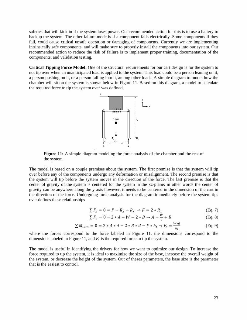
safeties that will kick in if the system loses power. Our recommended action for this is to use a battery to backup the system. The other failure mode is if a component fails electrically. Some components if they fail, could cause critical unsafe operation or damaging of components. Currently we are implementing intrinsically safe components, and will make sure to properly install the components into our system. Our recommended action to reduce the risk of failure is to implement proper training, documentation of the components, and validation testing. Critical Tipping Force Model: One of the structural requirements for our cart design is for the system to not tip over when an unanticipated load is applied to the system. This load could be a person leaning on it, a person pushing on it, or a person falling into it, among other loads. A simple diagram to model how the chamber will sit on the system is shown below in Figure 11. Based on this diagram, a model to calculate the required force to tip the system over was defined.
. Figure 11: A simple diagram modeling the force analysis of the chamber and the rest of the system.
The model is based on a couple premises about the system. The first premise is that the system will tip over before any of the components undergo any deformation or misalignment. The second premise is that the system will tip before the system moves in the direction of the force. The last premise is that the center of gravity of the system is centered for the system in the xz-plane; in other words the center of gravity can be anywhere along the y axis however, it needs to be centered in the dimension of the cart in the direction of the force. Undergoing force analysis for the diagram immediately before the system tips over defines these relationships
∑𝐹𝐹𝑥𝑥 = 0 = 𝐹𝐹 − 𝑅𝑅𝑥𝑥 − 𝑅𝑅𝑥𝑥 → 𝐹𝐹 = 2 ∗ 𝑅𝑅𝑥𝑥 (Eq. 7) ∑𝐹𝐹𝑐𝑐 = 0 = 2 ∗ 𝐴𝐴 −𝑊𝑊 − 2 ∗ 𝐵𝐵 → 𝐴𝐴 = 𝑊𝑊
2+ 𝐵𝐵 (Eq. 8)
∑𝑀𝑀𝐶𝐶𝐶𝐶𝐶𝐶 = 0 = 2 ∗ 𝐴𝐴 ∗ 𝑑𝑑 + 2 ∗ 𝐵𝐵 ∗ 𝑑𝑑 − 𝐹𝐹 ∗ ℎ𝑖𝑖 → 𝐹𝐹𝑖𝑖 = 𝑊𝑊∗𝑐𝑐ℎ𝑖𝑖
(Eq. 9)
where the forces correspond to the force labeled in Figure 11, the dimensions correspond to the dimensions labeled in Figure 11, and 𝐹𝐹𝑖𝑖 is the required force to tip the system. The model is useful in identifying the drivers for how we want to optimize our design. To increase the force required to tip the system, it is ideal to maximize the size of the base, increase the overall weight of the system, or decrease the height of the system. Out of theses parameters, the base size is the parameter that is the easiest to control.
23
MANUFACTURING PLANS Most of the design in our system is in the acquiring of components and organizing them on a cart. There are a few components that required some manufacturing to complete them. An in-depth manufacturing plan for each component can be found in Appendix F, and simple descriptions of each plan are outlined in the paragraphs below. The injector rails provided by Bosch are intended for multiple injectors; however, we only have the capability to use one injector. This means that we needed to machine down the rails, turn plugs, and weld them into the injector ports we are not utilizing. The next component is the bottom plate that supports the chamber. We manufactured this piece using a water jet. The plate needed to have a large opening surrounding the window as well as holes for the plate mounting screws and attachment to the aluminum frame. Another series of components that we manufactured was the framing for our cart. This we made out of aluminum extrusion by way of cutting and milling to length. This was the most accurate and material efficient method because of the inaccuracy of cutting the material using a band saw. Plumbing of the chamber for the nitrogen supply required a pipe cutter and a bender for 3/8 in. OD tubing. We measured and bent the tube after the cart was assembled to ensure clearance around other components within the system. Prospective manufacturing that has not yet been completed and will be completed in phase 2 of the project includes the top plate and high-pressure fuel support parts. The top plate will be outsourced to another machine shop, either on campus or off campus, to complete the shape requirements and tolerances that we need to satisfy. There will be also a black-oxide coating that will need to be applied to the piece so that it will conform to our safety and durability requirements. With regards to high-pressure support parts, there will be manufacturing of mounting hardware in a similar fashion to our cart framing, in addition to joints between components and shielding for the high-pressure system in entirety. These components will all be completed in phase 2. VALIDATION TESTING In order to validate our system, we conducted two primary tests. These were done in an effort to demonstrate system functionality in its current state. The two tests we performed, which were both done in the Walter E. Lay Automotive Laboratory, included a pressurization test of our inert gas exchange system and a spatial constraint test relative to our necessary space requirements. The validation testing plans for both of these tests can be found in Appendix H, and results of both tests are outlined in the sections below and on page 25. Tests beyond these will be required during phase 2 to further demonstrate system functionality in entirety, including the high-pressure components, but because high-pressure completion is a phase 2 task, we were not able to complete tasks beyond these two. Inert Gas Exchange We performed a functionality test of the inert gas exchange system for our prototype. On April 14th 2015, we went to test room 1122 in the Walter E. Lay Automotive Laboratory and performed the test. We began testing around 50-75 psi and checked the system for leaks. Any leaks that we found were sealed by either tightening the fitting more or reapplying Teflon tape to the fitting. Once all the leaks were sealed, we
24
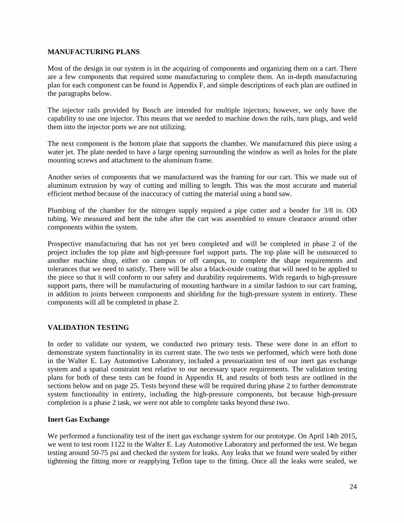
slowly pressurized our system in increments of 100 psi until we safely reached 600 psi. We then completely depressurized the system, and ran a full pressurization test. Starting at close to zero gauge pressure, we pressurized the chamber to 600 psi. Once the pressure stabilized, the chamber was then completely depressurized. During the entire test, the pressure inside the chamber was monitored with a LabVIEW program. Figure 12 on page 25 shows the pressure in the chamber for the entirety of the test, compared to ideal performance. We were able to verify the pressure in the chamber to be 588 psi. This test was able to verify that our inert gas exchange system satisfies our specifications for chamber pressure. Our sponsors specified that the chamber needs to be able to reach 40 bar of pressure, or 580.15 psi. Our test showed that we were able to safely pressurize to that pressure, and maintain that pressure for 10 seconds. We believe that with a more sophisticated controller we would be able to reach our target pressure of 600 psi.
Figure 12: Results of the pressurization test of our inert gas exchange system. We attempted to pressurize the chamber to 60 psi, but were only able to verify chamber pressure 588 psi. With a better controller, we are confident that our target pressure could be reached. Spatial Constraints We performed a test on the spatial constraints of our test bench. We were given specifications to be able to maneuver our test bench to certain locations within a test cell in the Quantitative Laser Diagnostics Laboratory in the Walter E. Lay Automotive Laboratory. We performed this test on April 14th 2015. For this test, we took the test bench to the test cell and performed our test. Based on the specified locations determined by Dr. Michael Gross, we were able to safely maneuver to the locations.
25
DESIGN DISCUSSION After completing the various elements throughout the design, development, and constructions phases of this project, we have a number of reflections regarding our designs and recommendations for work moving forward with our prototype. The sections that follow include what we would have done differently throughout the project, the strengths and weaknesses of our design, what can be improved in the design, and our recommendations to our sponsors and to the team moving forward with the project. Reflection on Process Had we known at the beginning of the design process what we know now about our design, we would have designed and laid out our system differently and possibly reduced the package size. For example, we were unable to use our pipe mounting brackets due to the fact that our stand was too small; if it had been made larger we would have been able to properly support all components on the stand and not had as many packaging issues with the plumbing. Also if we had known how difficult it was to properly tighten all components of the plumbing we would have found a way to leak test the individual components throughout assembly rather than only testing the complete final assembly and having to disassemble components in order to eliminate the leaks. Strengths of Design Our design utilizes aluminum extrusion in multiple locations throughout the assembly. This allows for easy additions and changes to the cart, which allows for the addition of shielding around the high-pressure fuel system to be added easily once the high-pressure fuel system is finalized and constructed. Our design also utilized many purchased components allowing for a concentration on the assembly of components and overall functionality rather than functionality of singular components of the system. Recommended Improvements We could have improved the waste collection mechanism. The way the fluid currently enters the container has a risk of disconnecting and creating an uncontrolled release of fuel vapors. Secondly, the handle used to raise and lower the chamber currently can bend significantly and cause failure of the part through extended use. Scissor Lift: We discovered once the scissor lift table was purchased, that the table would require additional components to operate. The toughest part to design for was that the lift table has a ¼” hex connection. We came together and designed a handwheel attachment for the lift that had a shaft adapter to attach to the ¼” hex connector. When testing the handwheel, we discovered that it functioned; however we are not confident that the adaptor is durable enough for long-term adjustments. We recommend taking the requirements for the adaptors and getting a single piece adaptor outsourced to a professional machine shop. We believe that our solution is sufficient; however we believe that the core of the problem is in our manufacturing technique, and that if a piece was machined with more advanced techniques this problem would be eliminated. Waste collection: The second aspect of our design that we recommend be reexamined is the plugging mechanism for the waste collection jar. We utilized a rubber stopper for our initial design. When we performed testing on our Nitrogen Exchange system, we found that at around 600 psi of pressure, the rubber stopper popped off the waste collection jar. Since this failure mode is not acceptable for testing, a redesign was necessary.
26

In order to correct this failure, we recommend one of two actions. The first solution is to cut the top of the rubber stopper such that a cap could fit around and screw onto the rubber stopper. The waste collection jar has threads around the top. Using this cap, we could utilize two methods of securing the rubber stopper - the friction from the rubber stopper as well as the downward pressure of the cap. The second possible solution involves cap and plug components that came with the waste collection jar. This solution uses a plastic cover that has three holes in it for vapors and fluid to enter and exit the jar. A cap then screws on top of the cover to secure it to the jar. We did not use this solution initially because the ⅛” OD tubing that the cover is design for flow in and out of the jar we felt did not allow for enough flow for testing. AUTHORS
William Crowe is a Mechanical Engineering student at The University of Michigan. He is interested in cars and has a desire to work in the automotive field. He graduated from The University of Detroit Jesuit High School in 2011 and grew up in Beverly Hills, MI. He is a Certified LabVIEW Associate Developer and has 2 years of test systems design and programming experience.
James Gorton is a Mechanical Engineering student at the University of Michigan. He anticipates graduating in May of 2015, and is looking to get hired at an engineering firm post-graduation. He graduated from the University of Detroit Jesuit High School in 2011, and grew up in Livonia, MI. He is an avid sports fan, especially of the local Detroit teams and University of Michigan athletics. He enjoys spending his time watching sports and playing video games with his friends. He dreams of owning a Corvette and living on the beach in Florida. Cameron Hoffman is a Mechanical Engineering student at the University of Michigan who anticipates graduating in May of 2015. Upon graduation, he plans to move to Seattle and intern with The Boeing Company for the summer. Completion of this internship and the summer will lead to either a full-time job with Boeing or a return to the University of Michigan to begin a Master's degree in Manufacturing Engineering. Cameron grew up in Eaton Rapids, Michigan, a small town south of Lansing, and in his free time, he enjoys running, cycling, and geocaching.
Taylor Pomeroy is a Mechanical Engineering student at the University of Michigan. He anticipates graduating in December of 2015, and is currently working at Montisa Health on patient recovery chairs. He grew up in the small town of Hartford in Southwestern Michigan. In his free time he enjoys reading, drawing, and watching movies.
27
REFERENCES [1] National Highway Traffic Safety Administration (NHTSA), and Environmental Protection Agency
(EPA). (2011). 2017-2025 model year light-duty vehicle GHG emissions and CAFE standards: Supplemental notice of intent (Supplemental Notice of Intent No. EPA-HQ-OAR-2010-0799). U.S. Government Publishing Office: Office of the Federal Register, NARA.
[2] Mosburger, M., Stach, T., & UM, Staff. (2015). ME450 W14 project plan bosch spray chamber
project. Unpublished manuscript. [3] Bosch gasoline direct injection. (2013).[Video/DVD] YouTube: Bosch Mobility Solutions. [4] Heywood, J. B. (1988). Internal combustion engine fundamentals. New York: McGraw-Hill. [5] Bosch Mobility Solutions. Gasoline direct injection. Retrieved January 27, 2015, from
http://www.bosch-mobility-solutions.com/en/de/powertrain/powertrain_systems_for_passenger_cars_1/direct_gasoline_injection/direct_gasoline_injection_23.html
[6] Fenske, G. R., Woodford, J., Wang, J., El-Hannouny, E., Schaefer, R., & Hamady, F. (2009).
Fabrication and characterization of micro-orifices for diesel fuel injectors. SAE International Journal of Fuels and Lubricants, 1(1), 910-919.
[7] Lee, C. S., Lee, K. H., Chon, M. S., & Kim, D. S. (2001). Spray structure and characteristics of
high-pressure gasoline injectors for direct-injection engine applications. Atomization and Sprays, 11(1), 35-48.
[8] Barabas, I., Todorut, I. A., Kocsis, L. B., & Baldean, D. L. (2010). Automated test bench for study
of the fuel injection process. Robotics and Automation Systems, 166-167. pp. 39-44. [9] Akinori, S., Atsushi, T., Keiso, T., & Minoru, O. (1998-04-10). In TOYOTA CENTRAL RES &
DEV, TOYOTA MOTOR CORP(Eds.), Apparatus for measuring spray pattern F02M65/00; G01M15/00; G01M15/04.
[10] De, C. M., Prodi, G., & Serra, G. (2009). Control method of a direct injection system of the common
rail type provided with a high-pressure fuel pump. Google Patents. [11] High-pressure solenoid injector HDEV 5(2013). No. 292000P148-C/CCA-201309-En). Germany:
Robert Bosch GmbH Gasoline Systems. [12] HP injection valve HDEV 5.2(2015). No. 2776067211). U.S.: Bosch Engineering North America
Motorsport. [13] High-pressure pump HDP 5(2013). No. 292000P146-C/CCA-201309-En). Germany: Robert Bosch
GmbH Gasoline Systems. [14] HP fuel pump HDP 5-LW(2015). No. 10543336971). U.S.: Bosch Engineering North America. [15] OSHA technical manual (OTM) Section VII: Chapter 1(1999). (Technical Manual No. TED 01-00-
015). U.S.: OSHA. [16] CRC handbook of chemistry and physics, 95th ed, 2014-2015. Retrieved January 2015, 2015, from
http://www.hbcpnetbase.com
28
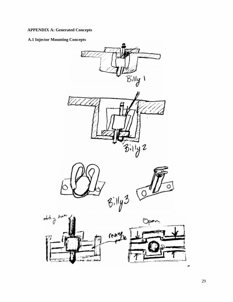
APPENDIX A: Generated Concepts A.1 Injector Mounting Concepts
29
30
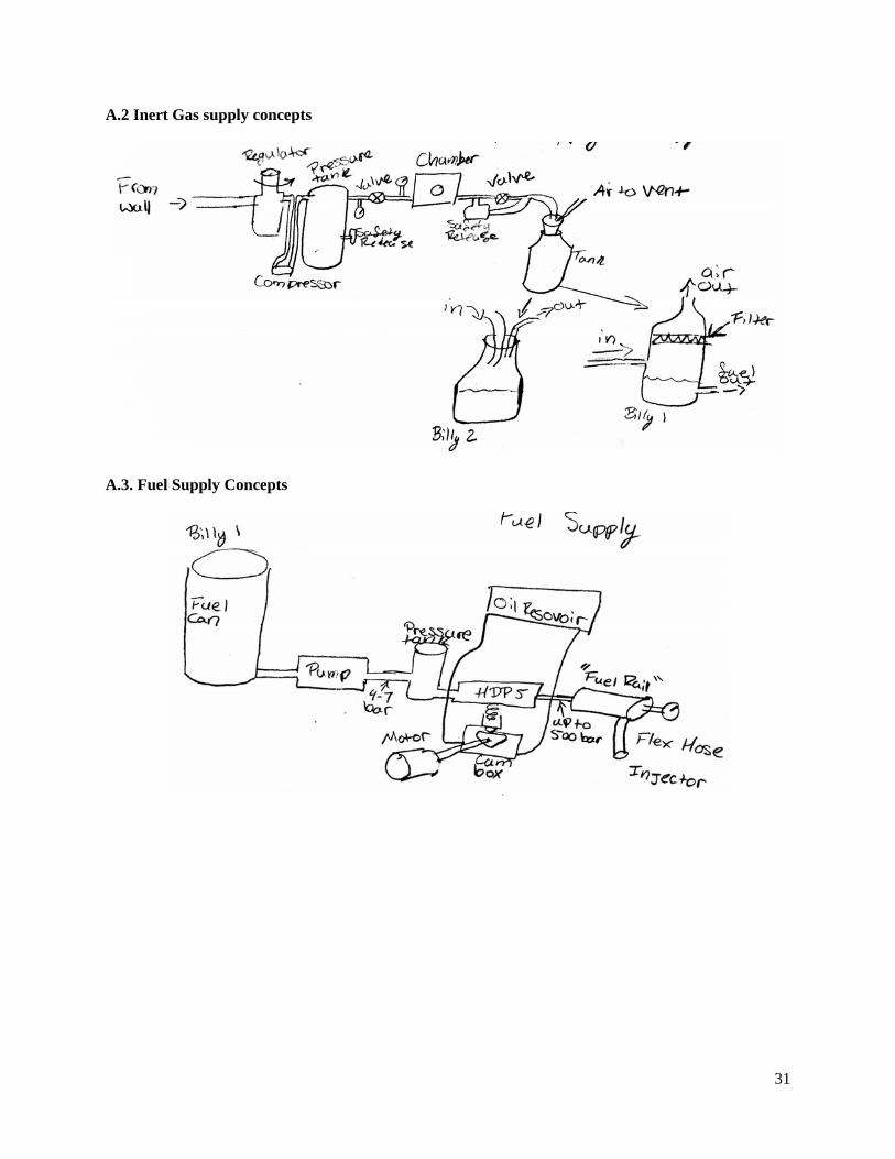
A.2 Inert Gas supply concepts
A.3. Fuel Supply Concepts
31
32
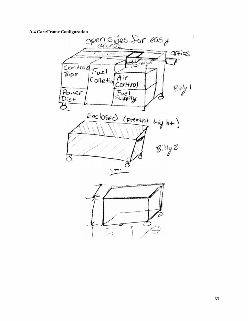
A.4 Cart/Frame Configuration
33
34
35
36
37
38
A.5 Chamber Securement Methods
39
40
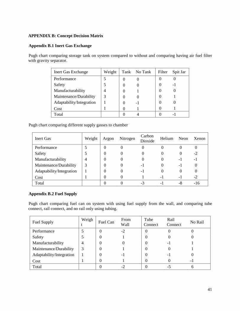
APPENDIX B: Concept Decision Matrix Appendix B.1 Inert Gas Exchange Pugh chart comparing storage tank on system compared to without and comparing having air fuel filter with gravity separator.
Inert Gas Exchange Weight Tank No Tank Filter Spit Jar Performance 5 0 0 0 0 Safety 5 0 0 0 -1 Manufacturability 4 0 1 0 0 Maintenance/Durability 3 0 0 0 1 Adaptability/Integration 1 0 -1 0 0 Cost 1 0 1 0 1 Total 0 4 0 -1
Pugh chart comparing different supply gasses to chamber
Inert Gas Weight Argon Nitrogen Carbon Dioxide Helium Neon Xenon
Performance 5 0 0 0 0 0 0 Safety 5 0 0 0 0 0 -2 Manufacturability 4 0 0 0 0 -1 -1 Maintenance/Durability 3 0 0 -1 0 -1 0 Adaptability/Integration 1 0 0 -1 0 0 0 Cost 1 0 0 1 -1 -1 -2 Total 0 0 -3 -1 -8 -16
Appendix B.2 Fuel Supply Pugh chart comparing fuel can on system with using fuel supply from the wall, and comparing tube connect, rail connect, and no rail only using tubing.
Fuel Supply Weight Fuel Can From
Wall Tube Connect
Rail Connect No Rail
Performance 5 0 -2 0 0 0 Safety 5 0 1 0 0 0 Manufacturability 4 0 0 0 -1 1 Maintenance/Durability 3 0 1 0 0 1 Adaptability/Integration 1 0 -1 0 -1 0 Cost 1 0 1 0 0 -1 Total 0 -2 0 -5 6
41
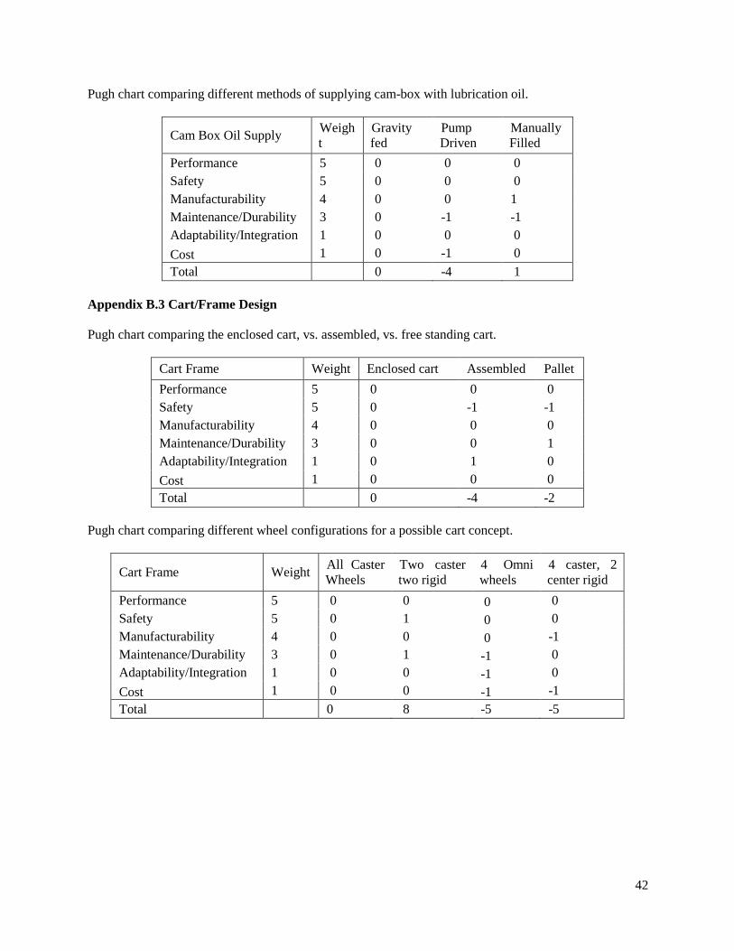
Pugh chart comparing different methods of supplying cam-box with lubrication oil.
Cam Box Oil Supply Weight
Gravity fed
Pump Driven
Manually Filled
Performance 5 0 0 0 Safety 5 0 0 0 Manufacturability 4 0 0 1 Maintenance/Durability 3 0 -1 -1 Adaptability/Integration 1 0 0 0 Cost 1 0 -1 0 Total 0 -4 1
Appendix B.3 Cart/Frame Design Pugh chart comparing the enclosed cart, vs. assembled, vs. free standing cart.
Cart Frame Weight Enclosed cart Assembled Pallet Performance 5 0 0 0 Safety 5 0 -1 -1 Manufacturability 4 0 0 0 Maintenance/Durability 3 0 0 1 Adaptability/Integration 1 0 1 0 Cost 1 0 0 0 Total 0 -4 -2
Pugh chart comparing different wheel configurations for a possible cart concept.
Cart Frame Weight All Caster Wheels
Two caster two rigid
4 Omni wheels
4 caster, 2 center rigid
Performance 5 0 0 0 0 Safety 5 0 1 0 0 Manufacturability 4 0 0 0 -1 Maintenance/Durability 3 0 1 -1 0 Adaptability/Integration 1 0 0 -1 0 Cost 1 0 0 -1 -1 Total 0 8 -5 -5
42

APPENDIX C: BILL OF MATERIALS The purpose of this section is to provide the list of components that will be used to complete this project. Each component has a description, Quantity, family, and the vendor that will provide the component with the cost to acquire it. See Master BOM.xlsx document uploaded to Final Report web page.
43
APPENDIX D: DETAILED ENGINEERING ANALYSIS AND EQUATIONS
The purpose of this section is to give an indepth and thorough representation of the engineering analysis performed and the equations used and the calculations completed to complete them.
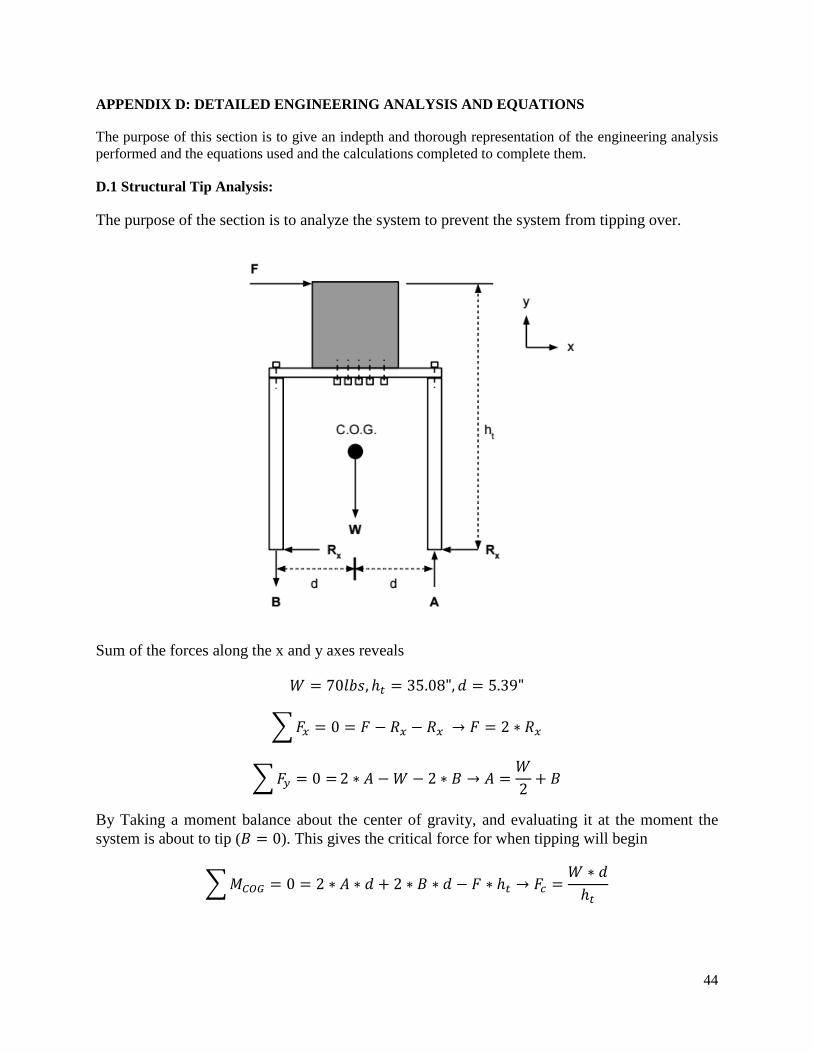
D.1 Structural Tip Analysis:
The purpose of the section is to analyze the system to prevent the system from tipping over.
Sum of the forces along the x and y axes reveals
𝑊𝑊 = 70𝑙𝑙𝑙𝑙𝑙𝑙,ℎ𝑖𝑖 = 35.08",𝑑𝑑 = 5.39"
�𝐹𝐹𝑥𝑥 = 0 = 𝐹𝐹 − 𝑅𝑅𝑥𝑥 − 𝑅𝑅𝑥𝑥 → 𝐹𝐹 = 2 ∗ 𝑅𝑅𝑥𝑥
�𝐹𝐹𝑐𝑐 = 0 = 2 ∗ 𝐴𝐴 −𝑊𝑊 − 2 ∗ 𝐵𝐵 → 𝐴𝐴 =𝑊𝑊2
+ 𝐵𝐵
By Taking a moment balance about the center of gravity, and evaluating it at the moment the system is about to tip (𝐵𝐵 = 0). This gives the critical force for when tipping will begin
�𝑀𝑀𝐶𝐶𝐶𝐶𝐶𝐶 = 0 = 2 ∗ 𝐴𝐴 ∗ 𝑑𝑑 + 2 ∗ 𝐵𝐵 ∗ 𝑑𝑑 − 𝐹𝐹 ∗ ℎ𝑖𝑖 → 𝐹𝐹𝑖𝑖 =𝑊𝑊 ∗ 𝑑𝑑ℎ𝑖𝑖
44

D.2 Nitrogen Supply Analysis
The purpose of this section is to analyze how much nitrogen is required to properly supply the system.
If we treat the nitrogen as an ideal gas with a compressibility, we can calculate the change in volume in pressurizing the gas.
State 1 is the state of the nitrogen within the cylinders. State 2 is the state of the nitrogen in the chamber.
Ideal Gas Law with compressibility:
𝑃𝑃 ∗ 𝑉𝑉 = 𝑍𝑍 ∗ 𝑅𝑅 ∗ 𝑇𝑇
If we assume an isothermal compression, then the compressed ideal gas law simplifies to
𝑃𝑃𝑖𝑖𝑐𝑐𝑐𝑐𝑖𝑖𝑖𝑖𝑐𝑐𝑖𝑖𝑐𝑐 ∗ 𝑉𝑉𝑖𝑖𝑐𝑐𝑐𝑐𝑖𝑖𝑖𝑖𝑐𝑐𝑖𝑖𝑐𝑐𝑍𝑍𝑖𝑖𝑐𝑐𝑐𝑐𝑖𝑖𝑖𝑖𝑐𝑐𝑖𝑖𝑐𝑐
=𝑃𝑃𝑖𝑖ℎ𝑐𝑐𝑚𝑚𝑚𝑚𝑖𝑖𝑐𝑐 ∗ 𝑉𝑉𝑖𝑖ℎ𝑐𝑐𝑚𝑚𝑚𝑚𝑖𝑖𝑐𝑐
𝑍𝑍𝑖𝑖ℎ𝑐𝑐𝑚𝑚𝑚𝑚𝑖𝑖𝑐𝑐
The required volume from the cylinder per test is
𝑉𝑉𝑖𝑖𝑐𝑐𝑐𝑐𝑖𝑖𝑖𝑖𝑐𝑐𝑖𝑖𝑐𝑐 =𝑍𝑍𝑖𝑖𝑐𝑐𝑐𝑐𝑖𝑖𝑖𝑖𝑐𝑐𝑖𝑖𝑐𝑐 ∗ 𝑃𝑃𝑖𝑖ℎ𝑐𝑐𝑚𝑚𝑚𝑚𝑖𝑖𝑐𝑐𝑍𝑍𝑖𝑖ℎ𝑐𝑐𝑚𝑚𝑚𝑚𝑖𝑖𝑐𝑐 ∗ 𝑃𝑃𝑖𝑖𝑐𝑐𝑐𝑐𝑖𝑖𝑖𝑖𝑐𝑐𝑖𝑖𝑐𝑐
∗ 𝑉𝑉𝑖𝑖ℎ𝑐𝑐𝑚𝑚𝑚𝑚𝑖𝑖𝑐𝑐
The number of cylinders required to supply our chamber for the number of tests is
𝑛𝑛𝑖𝑖𝑐𝑐𝑐𝑐𝑖𝑖𝑖𝑖𝑐𝑐𝑖𝑖𝑐𝑐𝑐𝑐 =𝑉𝑉𝑖𝑖𝑐𝑐𝑐𝑐𝑖𝑖𝑖𝑖𝑐𝑐𝑖𝑖𝑐𝑐/𝑖𝑖𝑖𝑖𝑐𝑐𝑖𝑖 ∗ 𝑛𝑛𝑖𝑖𝑖𝑖𝑐𝑐𝑖𝑖𝑐𝑐
𝑉𝑉𝑐𝑐𝑖𝑖𝑖𝑖𝑖𝑖𝑐𝑐𝑐𝑐𝑖𝑖𝑖𝑖𝑐𝑐𝑖𝑖𝑐𝑐
As of Design Review 3, we are still acquiring the specifications for the nitrogen supply, so a value could not be generated.
45
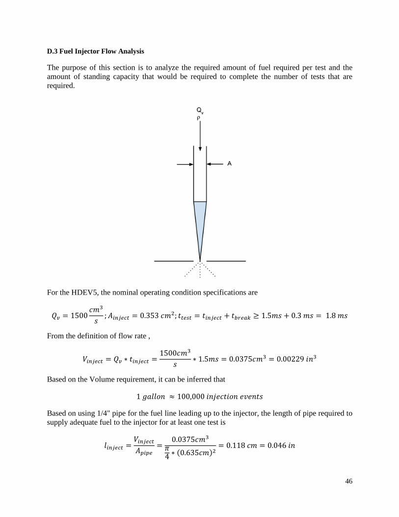
D.3 Fuel Injector Flow Analysis
The purpose of this section is to analyze the required amount of fuel required per test and the amount of standing capacity that would be required to complete the number of tests that are required.
For the HDEV5, the nominal operating condition specifications are
𝑄𝑄𝑣𝑣 = 1500𝑐𝑐𝑚𝑚3
𝑙𝑙;𝐴𝐴𝑖𝑖𝑖𝑖𝑖𝑖𝑖𝑖𝑖𝑖𝑖𝑖 = 0.353 𝑐𝑐𝑚𝑚2; 𝑡𝑡𝑖𝑖𝑖𝑖𝑐𝑐𝑖𝑖 = 𝑡𝑡𝑖𝑖𝑖𝑖𝑖𝑖𝑖𝑖𝑖𝑖𝑖𝑖 + 𝑡𝑡𝑚𝑚𝑐𝑐𝑖𝑖𝑐𝑐𝑏𝑏 ≥ 1.5𝑚𝑚𝑙𝑙 + 0.3 𝑚𝑚𝑙𝑙 = 1.8 𝑚𝑚𝑙𝑙
From the definition of flow rate ,
𝑉𝑉𝑖𝑖𝑖𝑖𝑖𝑖𝑖𝑖𝑖𝑖𝑖𝑖 = 𝑄𝑄𝑣𝑣 ∗ 𝑡𝑡𝑖𝑖𝑖𝑖𝑖𝑖𝑖𝑖𝑖𝑖𝑖𝑖 =1500𝑐𝑐𝑚𝑚3
𝑙𝑙∗ 1.5𝑚𝑚𝑙𝑙 = 0.0375𝑐𝑐𝑚𝑚3 = 0.00229 𝑖𝑖𝑛𝑛3
Based on the Volume requirement, it can be inferred that
1 𝑔𝑔𝑔𝑔𝑙𝑙𝑙𝑙𝑔𝑔𝑛𝑛 ≈ 100,000 𝑖𝑖𝑛𝑛𝑖𝑖𝑖𝑖𝑐𝑐𝑡𝑡𝑖𝑖𝑔𝑔𝑛𝑛 𝑖𝑖𝑣𝑣𝑖𝑖𝑛𝑛𝑡𝑡𝑙𝑙
Based on using 1/4" pipe for the fuel line leading up to the injector, the length of pipe required to supply adequate fuel to the injector for at least one test is
𝑙𝑙𝑖𝑖𝑖𝑖𝑖𝑖𝑖𝑖𝑖𝑖𝑖𝑖 =𝑉𝑉𝑖𝑖𝑖𝑖𝑖𝑖𝑖𝑖𝑖𝑖𝑖𝑖𝐴𝐴𝑝𝑝𝑖𝑖𝑝𝑝𝑖𝑖
=0.0375𝑐𝑐𝑚𝑚3
𝜋𝜋4 ∗ (0.635𝑐𝑐𝑚𝑚)2
= 0.118 𝑐𝑐𝑚𝑚 = 0.046 𝑖𝑖𝑛𝑛
46
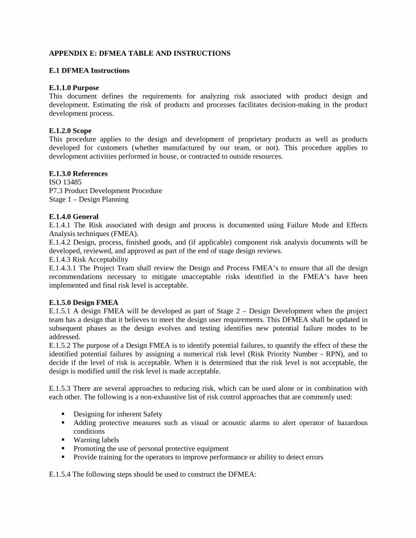
APPENDIX E: DFMEA TABLE AND INSTRUCTIONS E.1 DFMEA Instructions E.1.1.0 Purpose This document defines the requirements for analyzing risk associated with product design and development. Estimating the risk of products and processes facilitates decision-making in the product development process. E.1.2.0 Scope This procedure applies to the design and development of proprietary products as well as products developed for customers (whether manufactured by our team, or not). This procedure applies to development activities performed in house, or contracted to outside resources. E.1.3.0 References ISO 13485 P7.3 Product Development Procedure Stage 1 – Design Planning E.1.4.0 General E.1.4.1 The Risk associated with design and process is documented using Failure Mode and Effects Analysis techniques (FMEA). E.1.4.2 Design, process, finished goods, and (if applicable) component risk analysis documents will be developed, reviewed, and approved as part of the end of stage design reviews. E.1.4.3 Risk Acceptability E.1.4.3.1 The Project Team shall review the Design and Process FMEA’s to ensure that all the design recommendations necessary to mitigate unacceptable risks identified in the FMEA’s have been implemented and final risk level is acceptable. E.1.5.0 Design FMEA E.1.5.1 A design FMEA will be developed as part of Stage 2 – Design Development when the project team has a design that it believes to meet the design user requirements. This DFMEA shall be updated in subsequent phases as the design evolves and testing identifies new potential failure modes to be addressed. E.1.5.2 The purpose of a Design FMEA is to identify potential failures, to quantify the effect of these the identified potential failures by assigning a numerical risk level (Risk Priority Number - RPN), and to decide if the level of risk is acceptable. When it is determined that the risk level is not acceptable, the design is modified until the risk level is made acceptable. E.1.5.3 There are several approaches to reducing risk, which can be used alone or in combination with each other. The following is a non-exhaustive list of risk control approaches that are commonly used: Designing for inherent Safety Adding protective measures such as visual or acoustic alarms to alert operator of hazardous
conditions Warning labels Promoting the use of personal protective equipment Provide training for the operators to improve performance or ability to detect errors
E.1.5.4 The following steps should be used to construct the DFMEA:
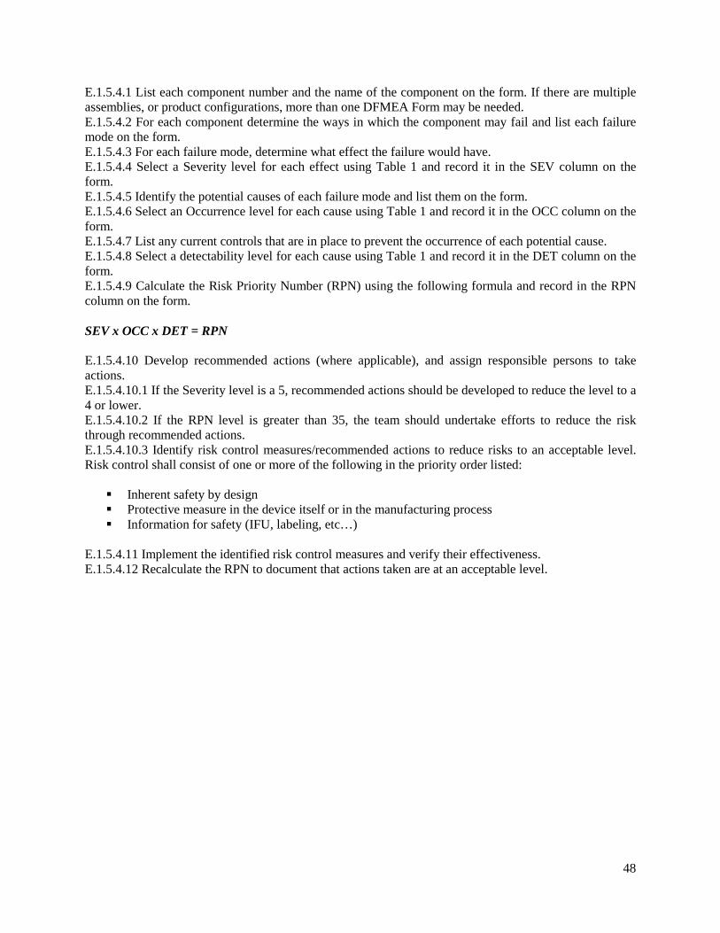
E.1.5.4.1 List each component number and the name of the component on the form. If there are multiple assemblies, or product configurations, more than one DFMEA Form may be needed. E.1.5.4.2 For each component determine the ways in which the component may fail and list each failure mode on the form. E.1.5.4.3 For each failure mode, determine what effect the failure would have. E.1.5.4.4 Select a Severity level for each effect using Table 1 and record it in the SEV column on the form. E.1.5.4.5 Identify the potential causes of each failure mode and list them on the form. E.1.5.4.6 Select an Occurrence level for each cause using Table 1 and record it in the OCC column on the form. E.1.5.4.7 List any current controls that are in place to prevent the occurrence of each potential cause. E.1.5.4.8 Select a detectability level for each cause using Table 1 and record it in the DET column on the form. E.1.5.4.9 Calculate the Risk Priority Number (RPN) using the following formula and record in the RPN column on the form. SEV x OCC x DET = RPN E.1.5.4.10 Develop recommended actions (where applicable), and assign responsible persons to take actions. E.1.5.4.10.1 If the Severity level is a 5, recommended actions should be developed to reduce the level to a 4 or lower. E.1.5.4.10.2 If the RPN level is greater than 35, the team should undertake efforts to reduce the risk through recommended actions. E.1.5.4.10.3 Identify risk control measures/recommended actions to reduce risks to an acceptable level. Risk control shall consist of one or more of the following in the priority order listed: Inherent safety by design Protective measure in the device itself or in the manufacturing process Information for safety (IFU, labeling, etc…)
E.1.5.4.11 Implement the identified risk control measures and verify their effectiveness. E.1.5.4.12 Recalculate the RPN to document that actions taken are at an acceptable level.
48
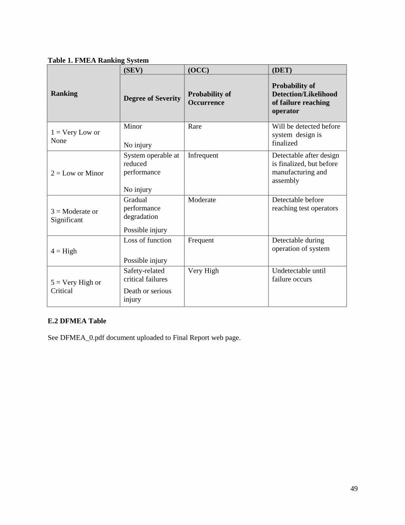
Table 1. FMEA Ranking System
Ranking
(SEV) (OCC) (DET)
Degree of Severity Probability of Occurrence
Probability of Detection/Likelihood of failure reaching operator
1 = Very Low or None
Minor Rare Will be detected before system design is finalized No injury
2 = Low or Minor
System operable at reduced performance
Infrequent Detectable after design is finalized, but before manufacturing and assembly
No injury
3 = Moderate or Significant
Gradual performance degradation
Moderate Detectable before reaching test operators
Possible injury
4 = High Loss of function Frequent Detectable during
operation of system Possible injury
5 = Very High or Critical
Safety-related critical failures
Very High Undetectable until failure occurs
Death or serious injury
E.2 DFMEA Table See DFMEA_0.pdf document uploaded to Final Report web page.
49
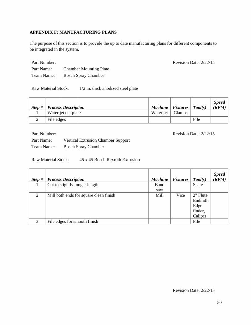
APPENDIX F: MANUFACTURING PLANS The purpose of this section is to provide the up to date manufacturing plans for different components to be integrated in the system. Part Number: Revision Date: 2/22/15 Part Name: Chamber Mounting Plate Team Name: Bosch Spray Chamber Raw Material Stock: 1/2 in. thick anodized steel plate
Step # Process Description Machine Fixtures Tool(s) Speed (RPM)
1 Water jet cut plate Water jet Clamps 2 File edges File
Part Number:
Revision Date: 2/22/15 Part Name: Vertical Extrusion Chamber Support Team Name: Bosch Spray Chamber
Raw Material Stock: 45 x 45 Bosch Rexroth Extrusion
Step # Process Description Machine Fixtures Tool(s) Speed (RPM)
1 Cut to slightly longer length Band saw
Scale
2 Mill both ends for square clean finish Mill Vice 2" Flute Endmill, Edge finder, Caliper
3 File edges for smooth finish File
Revision Date: 2/22/15
50
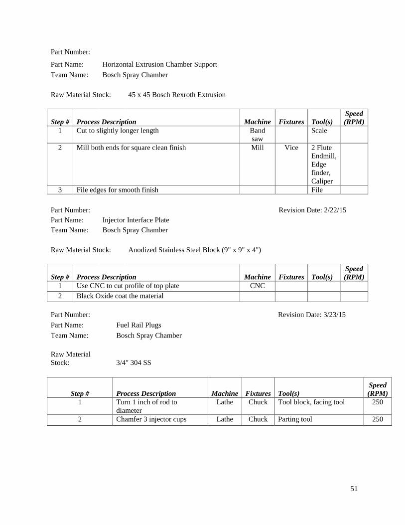
Part Number:
Part Name: Horizontal Extrusion Chamber Support
Team Name: Bosch Spray Chamber
Raw Material Stock: 45 x 45 Bosch Rexroth Extrusion
Step # Process Description Machine Fixtures Tool(s) Speed (RPM)
1 Cut to slightly longer length Band saw
Scale
2 Mill both ends for square clean finish Mill Vice 2 Flute Endmill, Edge finder, Caliper
3 File edges for smooth finish File
Part Number: Revision Date: 2/22/15 Part Name: Injector Interface Plate
Team Name: Bosch Spray Chamber Raw Material Stock: Anodized Stainless Steel Block (9" x 9" x 4")
Step # Process Description Machine Fixtures Tool(s) Speed (RPM)
1 Use CNC to cut profile of top plate CNC 2 Black Oxide coat the material
Part Number: Revision Date: 3/23/15 Part Name: Fuel Rail Plugs Team Name: Bosch Spray Chamber Raw Material Stock: 3/4" 304 SS
Step # Process Description Machine Fixtures Tool(s) Speed (RPM)
1 Turn 1 inch of rod to diameter
Lathe Chuck Tool block, facing tool 250
2 Chamfer 3 injector cups Lathe Chuck Parting tool 250
51
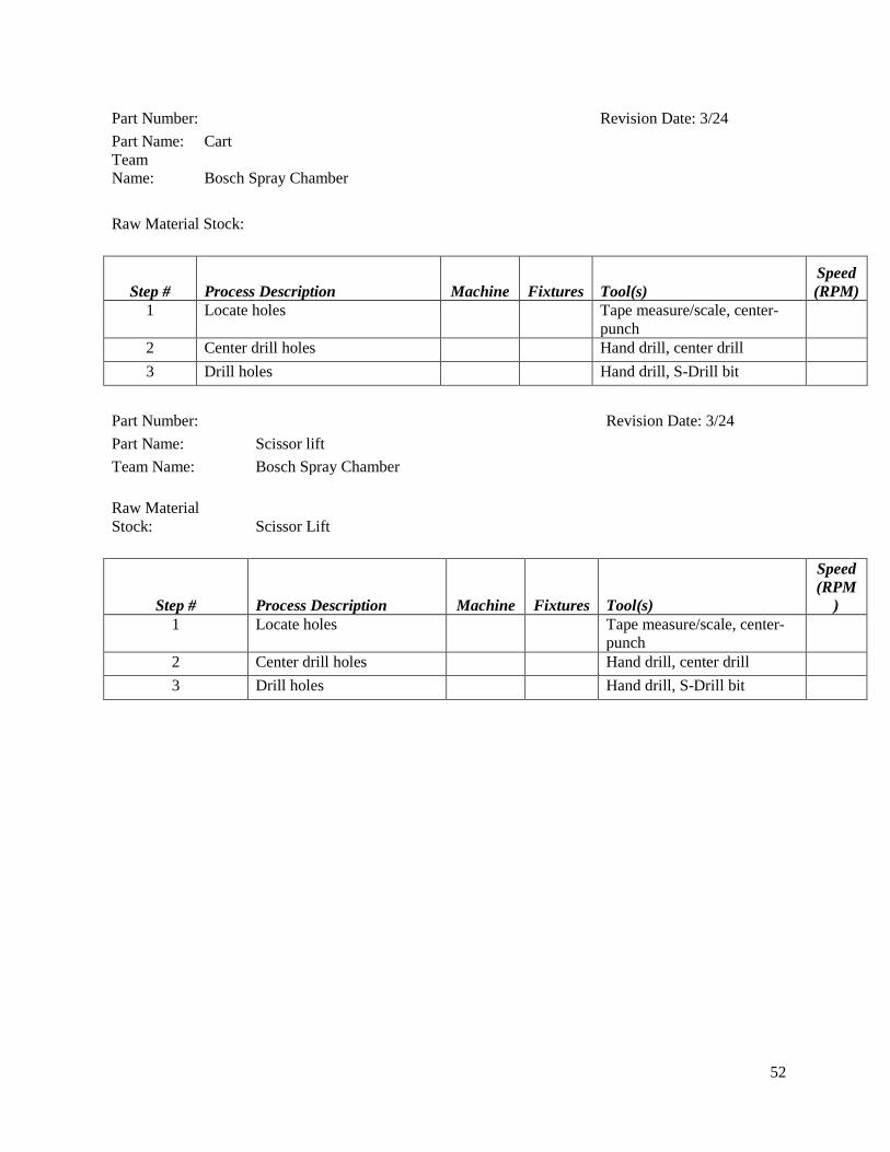
Part Number: Revision Date: 3/24 Part Name: Cart Team Name: Bosch Spray Chamber Raw Material Stock:
Step # Process Description Machine Fixtures Tool(s) Speed (RPM)
1 Locate holes Tape measure/scale, center-punch
2 Center drill holes Hand drill, center drill 3 Drill holes Hand drill, S-Drill bit
Part Number: Revision Date: 3/24 Part Name: Scissor lift Team Name: Bosch Spray Chamber Raw Material Stock: Scissor Lift
Step # Process Description Machine Fixtures Tool(s)
Speed (RPM
) 1 Locate holes Tape measure/scale, center-
punch
2 Center drill holes Hand drill, center drill 3 Drill holes Hand drill, S-Drill bit
52
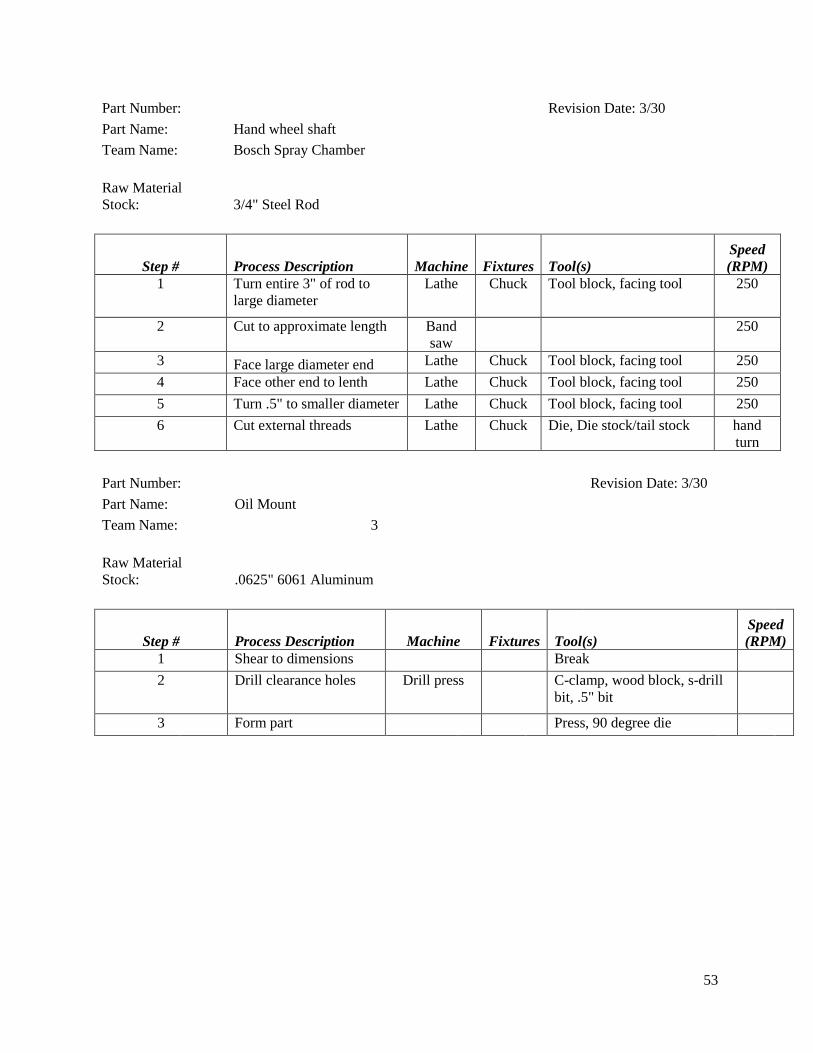
Part Number: Revision Date: 3/30 Part Name: Hand wheel shaft Team Name: Bosch Spray Chamber Raw Material Stock: 3/4" Steel Rod
Step # Process Description Machine Fixtures Tool(s) Speed (RPM)
1 Turn entire 3" of rod to large diameter
Lathe Chuck Tool block, facing tool 250
2 Cut to approximate length Band saw
250
3 Face large diameter end Lathe Chuck Tool block, facing tool 250 4 Face other end to lenth Lathe Chuck Tool block, facing tool 250 5 Turn .5" to smaller diameter Lathe Chuck Tool block, facing tool 250 6 Cut external threads Lathe Chuck Die, Die stock/tail stock hand
turn Part Number: Revision Date: 3/30 Part Name: Oil Mount Team Name: 3 Raw Material Stock: .0625" 6061 Aluminum
Step # Process Description Machine Fixtures Tool(s) Speed (RPM)
1 Shear to dimensions Break 2 Drill clearance holes Drill press C-clamp, wood block, s-drill
bit, .5" bit
3 Form part Press, 90 degree die
53
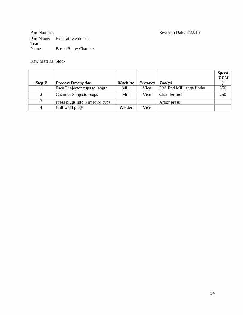
Part Number: Revision Date: 2/22/15 Part Name: Fuel rail weldment Team Name: Bosch Spray Chamber Raw Material Stock:
Step # Process Description Machine Fixtures Tool(s)
Speed (RPM
) 1 Face 3 injector cups to length Mill Vice 3/4" End Mill, edge finder 350 2 Chamfer 3 injector cups Mill Vice Chamfer tool 250 3 Press plugs into 3 injector cups Arbor press 4 Butt weld plugs Welder Vice
54
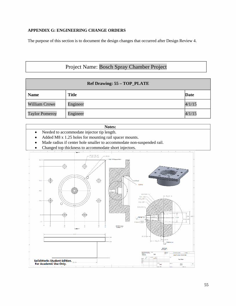
APPENDIX G: ENGINEERING CHANGE ORDERS The purpose of this section is to document the design changes that occurred after Design Review 4.
Project Name: Bosch Spray Chamber Project
Ref Drawing: 55 – TOP_PLATE
Name Title Date
William Crowe Engineer 4/1/15
Taylor Pomeroy Engineer 4/1/15
Notes: • Needed to accommodate injector tip length. • Added M8 x 1.25 holes for mounting rail spacer mounts. • Made radius if center hole smaller to accommodate non-suspended rail. • Changed top thickness to accommodate short injectors.
55
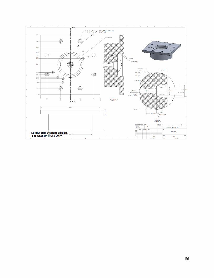
56
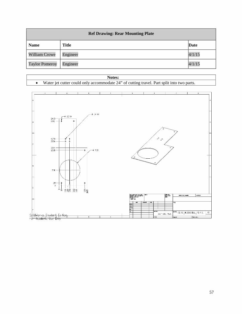
Ref Drawing: Rear Mounting Plate
Name Title Date
William Crowe Engineer 4/1/15
Taylor Pomeroy Engineer 4/1/15
Notes:
• Water jet cutter could only accommodate 24” of cutting travel. Part split into two parts.
57
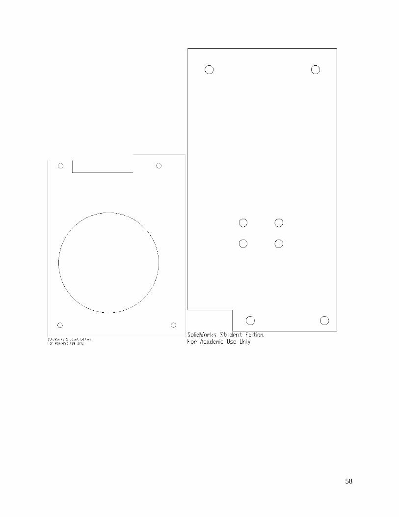
58
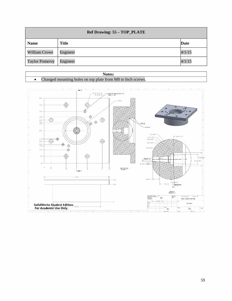
Ref Drawing: 55 – TOP_PLATE
Name Title Date
William Crowe Engineer 4/1/15
Taylor Pomeroy Engineer 4/1/15
Notes:
• Changed mounting holes on top plate from M8 to Inch screws.
59
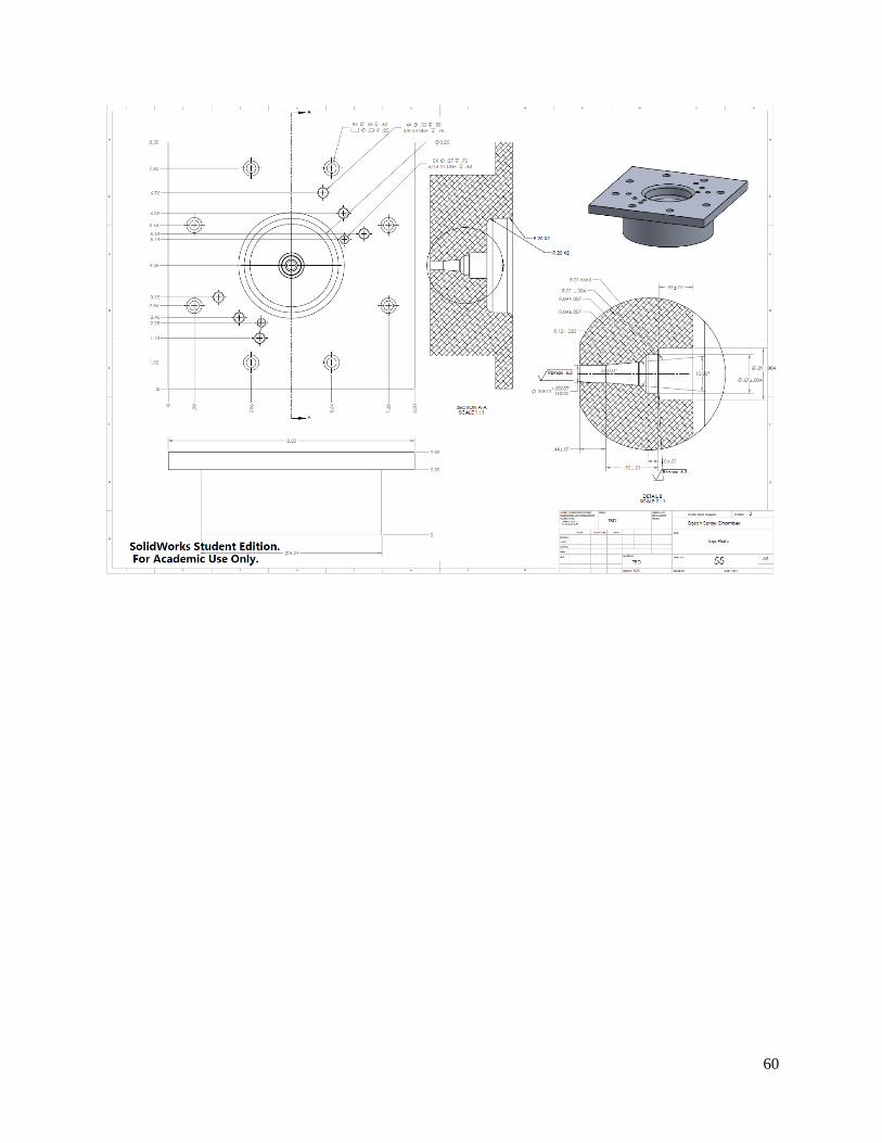
60
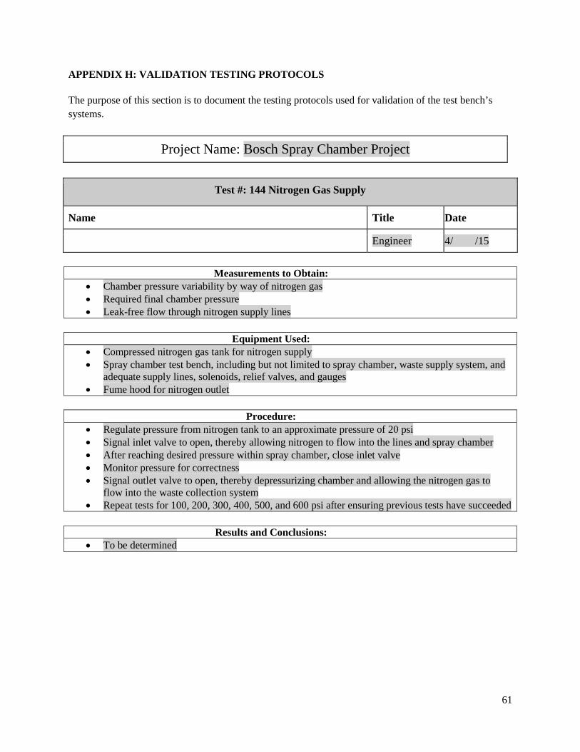
APPENDIX H: VALIDATION TESTING PROTOCOLS The purpose of this section is to document the testing protocols used for validation of the test bench’s systems.
Project Name: Bosch Spray Chamber Project
Test #: 144 Nitrogen Gas Supply
Name Title Date
Engineer 4/ /15
Measurements to Obtain: • Chamber pressure variability by way of nitrogen gas • Required final chamber pressure • Leak-free flow through nitrogen supply lines
Equipment Used:
• Compressed nitrogen gas tank for nitrogen supply • Spray chamber test bench, including but not limited to spray chamber, waste supply system, and
adequate supply lines, solenoids, relief valves, and gauges • Fume hood for nitrogen outlet
Procedure:
• Regulate pressure from nitrogen tank to an approximate pressure of 20 psi • Signal inlet valve to open, thereby allowing nitrogen to flow into the lines and spray chamber • After reaching desired pressure within spray chamber, close inlet valve • Monitor pressure for correctness • Signal outlet valve to open, thereby depressurizing chamber and allowing the nitrogen gas to
flow into the waste collection system • Repeat tests for 100, 200, 300, 400, 500, and 600 psi after ensuring previous tests have succeeded
Results and Conclusions:
• To be determined
61
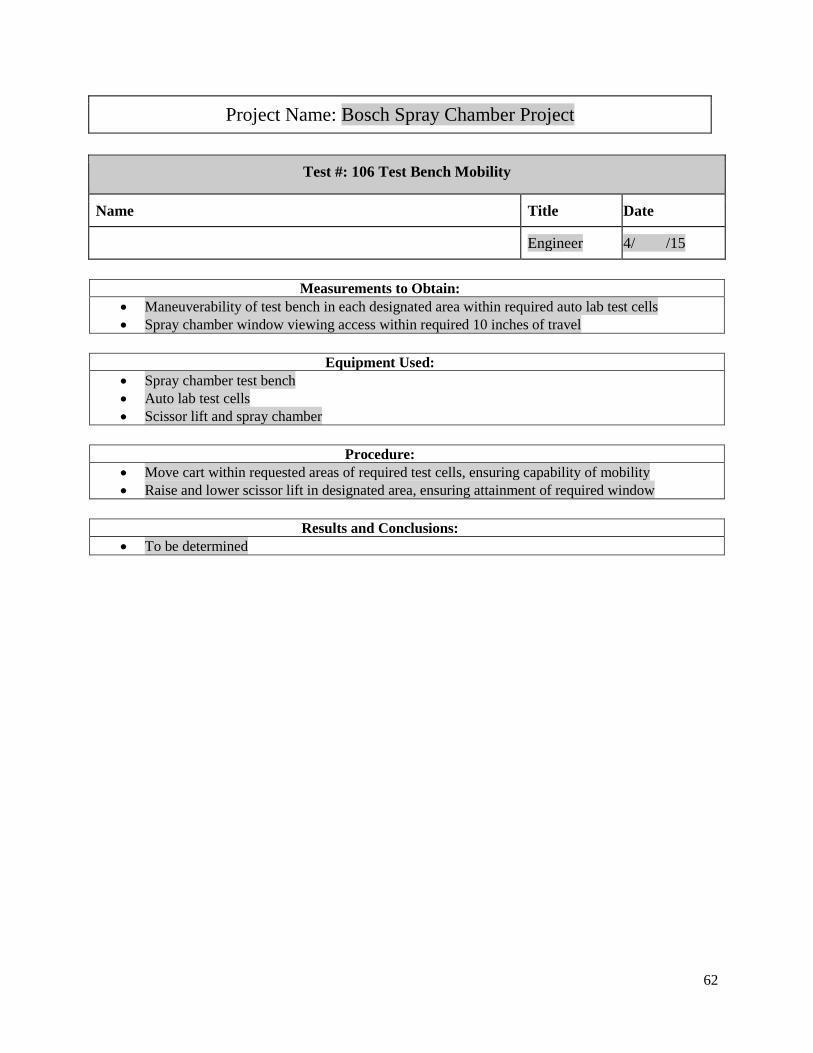
Project Name: Bosch Spray Chamber Project
Test #: 106 Test Bench Mobility
Name Title Date
Engineer 4/ /15
Measurements to Obtain: • Maneuverability of test bench in each designated area within required auto lab test cells • Spray chamber window viewing access within required 10 inches of travel
Equipment Used:
• Spray chamber test bench • Auto lab test cells • Scissor lift and spray chamber
Procedure:
• Move cart within requested areas of required test cells, ensuring capability of mobility • Raise and lower scissor lift in designated area, ensuring attainment of required window
Results and Conclusions:
• To be determined
62
APPENDIX I: INDIVIDUAL ETHICS AND ECOLOGICAL STATEMENTS The purpose of this section is to provide our thoughts on the ethical and ecological responsibilities relating to our project. Statement on Ethics: William Crowe Ethics plays a big part in our design process; one of the main concerns for our project was safely operating. Our project deals with dangerous chemicals at explosive pressures. We have only utilized safe materials and components, ensuring that any component is capable of the maximum pressure possible, pressure relief vales at any enclosed section, all material used is compatible with the chemicals being used, and through progressive testing ensuring that our system operates properly. To ensure all electronics will safely operate within our system, anything that can be in direct contact with fuel is intrinsically safe, meaning that it will not allow a static charge to the fuel causing possible ignition, secondly this means that if there is an explosion within the sensor it is built to handle it and will not rupture. In ensuring the materials we both did our own research as well as consulted our sponsors who have a lot of knowledge about fuel safe materials. After consulting our sponsors, to ensure all materials will not degrade when exposed to the fluids anticipated, after concluding our research all of our material in direct contact with fuel is stainless steel, PTFE (Teflon), or glass. Although it increased the cost of the system we utilized this to prevent future material degradation that could lead to a high pressure leak. As a secondary precaution we have allowed for an acrylic shield to be utilized surrounding any high pressure components. Although this is not something that we will implement due to delays in delivery we have allowed ample space for the implementation of this in the second phase of the project. This shielding will protect the users from the leak coming out at 8000 psi. In order to properly test our system each component will be tested beginning at a low pressure to ensure basic functionality at low pressures, then incrementally increasing the pressure, checking for leaks at each pressure, and eventually testing at the maximum anticipated operating pressures multiple times to ensure repeatable functionality. After completing all of this we will be able to confidently say that our system safely operates to specifications. Statement on Environmental Impact: William Crowe Our project has environmental impact as a background concern. We have to choose safety over sustainability, restricting our materials to a select few possible options. We did choose a minimalist design only utilizing materials where necessary and not having an excess of materials. Secondly much of our system came from donated components that had previously been used in another application. This removes the material manufacturing reducing our impact on the environment. From the chamber to fuel rails to sensors they all are components that are either reused or came off an optimized manufacturing line. In addition the components that we did use are for the most part mass produced components that are already optimally produced minimizing impact. Our product has the goal of helping our environment as well. Our product will be utilized to improve research on sustainable fuels as well as reduce the current impact of vehicles. Once our project is no longer being utilized and is replaced our system can be dissected and material heavy and costly components can be reused to reduce costs of future products, while other materials can be recycled as they are mostly aluminum and steel components.
63
Statement on Ethics: James Gorton Our team has worked in an ethical manner, to the best of our knowledge and abilities, throughout the course of this project. We have had to consult many people for help in designing and constructing this project because it required skills and knowledge that we had not developed up to this point in our engineering careers. An example of this is seeking out the help of Tom Marino for advice on plumbing our system. We also looked to Charlie and John in the MEX50 machine shop for their advice in the manufacturing of components. We also have tried to communicate with all sponsors, advisors, customers, and instructors in a professional manner. One of our objectives for any presentation that we had for a design review or other meeting with our sponsors has been to dressed well. These are just a few examples of how we as a team and a group of individuals, have attempted to act and work ethically on this project. Statement on Environmental Impact: James Gorton While working on this project, we have been limited on the selection of materials and the ways that we could produce components. A large aspect of the system design for this project is to research the materials that we would be using so that they would accomplish the task we have been given but also would be cost effective, material use effective, and energy effective. Most of our components were either given to us by our sponsor or a component that did not have much variation in being able to be used for our project, but when we could we tried to be consistent in size and energy use so that we wouldn't need extra parts to incorporate a component. It takes a lot of energy to take metal and manufacture them into parts so we have tried to be efficient with our use of components so that the components interface as uniformly as possible, even if that costs a little bit extra in price. We have also taken the attitude of "Measure twice, cut once" in manufacturing components so that we do not create unnecessary waste when manufacturing components. The prototype we are constructing will be used with hazardous materials like gasoline, ethanol, and nitrogen. This consideration will have to be taken into account when the prototype will no longer be of service. However, since it will be used in a research application, the components that we have purchased and integrated into our design can be used for other projects to the discretion of our sponsors.
64
Statement on Ethics: Cameron Hoffman In a project sponsored by industry such as ours, a number of factors differ from projects sponsored by the university or projects used to creatively solve world problems in ways that have not yet been done before. The biggest of these differences is that our solution can drastically impact the profits of our sponsor, depending on how well our testing apparatus works. Furthermore, our project incorporates incredibly dangerous pressures, and this combined with the potential impact on the business of our sponsor, has called for ethical considerations in all elements of our designs, safety precautions, and testing plans. In order to remain ethical in our designs, our group selected components and designed components with safety as our number one priority. The functionality of the system is obviously a concern, but a dangerous, functioning system is non-ideal, so in our selection of components, we ensured all components were rated well beyond the pressure and mass requirements. By doing so, we ensured the safety of all persons using the device or in the vicinity of the device while in use from the standpoint of component failure. With our own individual component designs, we too took into consideration the necessary material strengths to withstand the pressures of the system at large. This similarly ensured the safety of the operators of the device. With regards to assessing failures in the system, our team did a failure mode analysis, and for this we looked at each of the components in our system and the ways each of these components could possibly fail in worse case scenarios. Then, we assessed the danger of these failures and established benchmarks for potential failures that needed addressing. For each of these, we created a plan of action regarding ways to reduce risks, which ensured more safety within our system. In terms of ethics with regards to achieving success for our sponsor, our team has done the best at creating a quality product at minimized cost for the company. Bosch is a profit-driven company, and as such, our system will help drive new products and new profits. In order to stay within this mindset, our group has ensured all parts ordered are approved by our sponsor and fit within the required budget while still meeting the project requirements. Getting this approval ensured we were making the ethical decisions in our construction of the prototype, and our lack of frivolous spending ensured we maintained the vision of the company at large. As outlined, our decisions with regards designs, safety precautions, and testing plans have all been ethical, given the attention to detail we put into ensuring quality, cost-effective components. Furthermore, our analysis of failure modes ensures that our product, which is within the requested specifications, is safe for use in the desired manner. Statement on Environmental Impact: Cameron Hoffman There are two aspects of our project that relate to the sustainability and environmental impact of our design. Firstly, is the design itself. When designing our system, our team did not pay the most attention to the material types used because components were selected on the basis that they were required to withstand the pressures of our system. Because these components are high pressure, only select materials are available for use, and as such, we were not able to assess environmental impact. Furthermore, at the end of the lifecycle of our system, components will be recycled for later use in other systems, sold to others for similar use, or recycled because they are no longer fit for use. This too, was unavoidable. At this point, the biggest difference we could have made as a team was ordering less components and having more foresight in our design. Some components that have been ordered can no longer work with our design because of design changes that have happened throughout the process, and with slightly more forward vision, this could have been avoided. This is the way I would go about fixing our faults.
65

The second aspect of our design, however, is the way it is used. Our project’s focus is on sustainability: our project creates the opportunity to create better fuel injectors, which in turn improves fuel economy and reduces environmental impact. This fact is our team’s mission statement with regards to the purpose of our prototype. Thus, despite our design not accounting for the most sustainable materials, our project will be used to reduce environmental impact in the automotive industry, and thus is better for the environment.
66
Statement on Ethics: Taylor Pomeroy With our project, there has been a need for inherent safety of all components of our design. Working with dangerous equipment and materials leads to an ethical responsibility for all of the work that we put in. All the safety aspects regarding the high pressure equipment need to be designed so that there are multiple fail-safes to prevent any sort of user injury. We addressed these issues in a few different ways. Firstly, we used a DFMEA to identify all the possible failure modes in our design. We took a look at which components would fail, the severity of their failure, and what corrective actions we could take to reduce the chances or severity of such an event. This was performed with our best engineering judgement. Secondly, when sourcing components, specification sheets were read and evaluated for their safety. This includes designing with an adequate safety factor for the required input and output factors. Finally, all design aspects were reviewed by all members of our team, and when we had further concerns, we asked for an external source to review our designs for their validity and safety. This responsibility for user safety was an ethical responsibility for our group. We went about our design with our best engineering judgement as a whole, and made sure that each aspect of the design was created and selected with care. The first fundamental canon of the ASME Code of Ethics is “Engineers shall hold paramount the safety, health and welfare of the public in the performance of their professional duties.” As a team, we strived to follow this with the entirety of our engineering knowledge and skills. Statement on Environmental Impact: Taylor Pomeroy The test bench we have designed will be used to obtain data for direct injection spray events. The purpose of testing these injectors is to improve their performance in actual engine applications. Direct injection engines can achieve higher compression ratios for before ignition, which leads to better fuel economies in vehicles. This move in industry is driven by an EPA requirement of increased MPGs in all new vehicles. The results of testing from our test bench will hopefully have a dramatic environmental impact. With over 1 billion automobiles worldwide, and carbon emissions being a major concern, increasing the miles per gallon of all new automobiles is a crucial step in reducing emissions. Compared to the resources we have used in completing this project, our test bench has a huge potential to impact the environment. The current plan for testing and the test bench is a minimum of five years of testing capabilities, with the potential for much more than that.
67