ME 111: Engineering Drawing - Indian Institute of ... Proj of pts and Lines.pdf · ME 111:...
41
ME 111: Engineering Drawing Lecture 6 16-08-2011 Projection of Points and 1 Projection of Points and Projection of Lines Indian Institute of Technology Guwahati Guwahati – 781039
-
Upload
nguyendieu -
Category
Documents
-
view
234 -
download
4
Transcript of ME 111: Engineering Drawing - Indian Institute of ... Proj of pts and Lines.pdf · ME 111:...
ME 111: Engineering DrawingLecture 6
16-08-2011Projection of Points and
1
Projection of Points and Projection of Lines
Indian Institute of Technology GuwahatiGuwahati – 781039
Projection of Points(Orthographic)
P
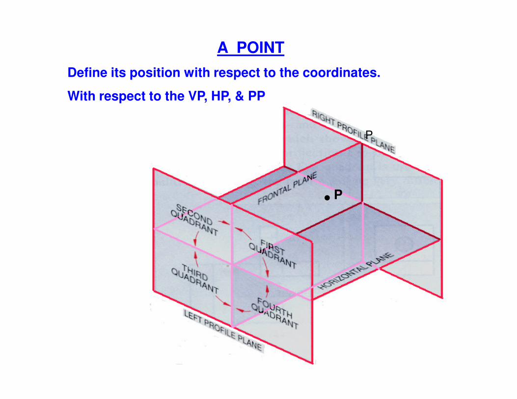
A POINTDefine its position with respect to the coordinates.
With respect to the VP, HP, & PP
PP
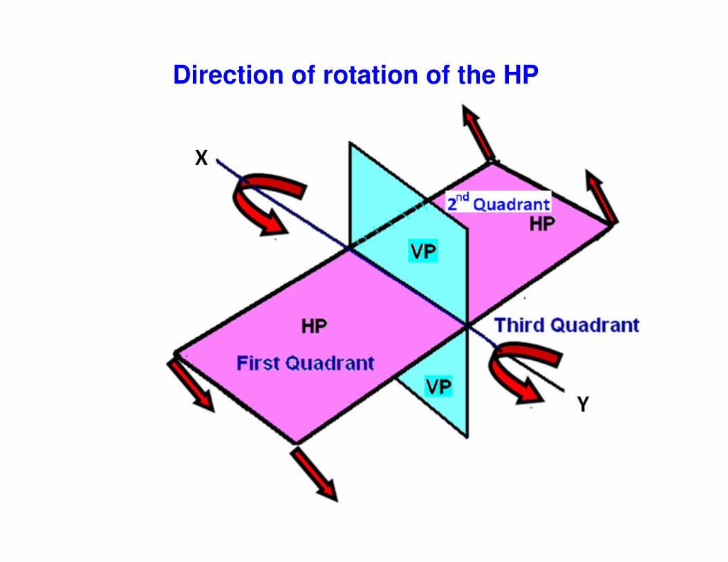
Direction of rotation of the HP

Convention
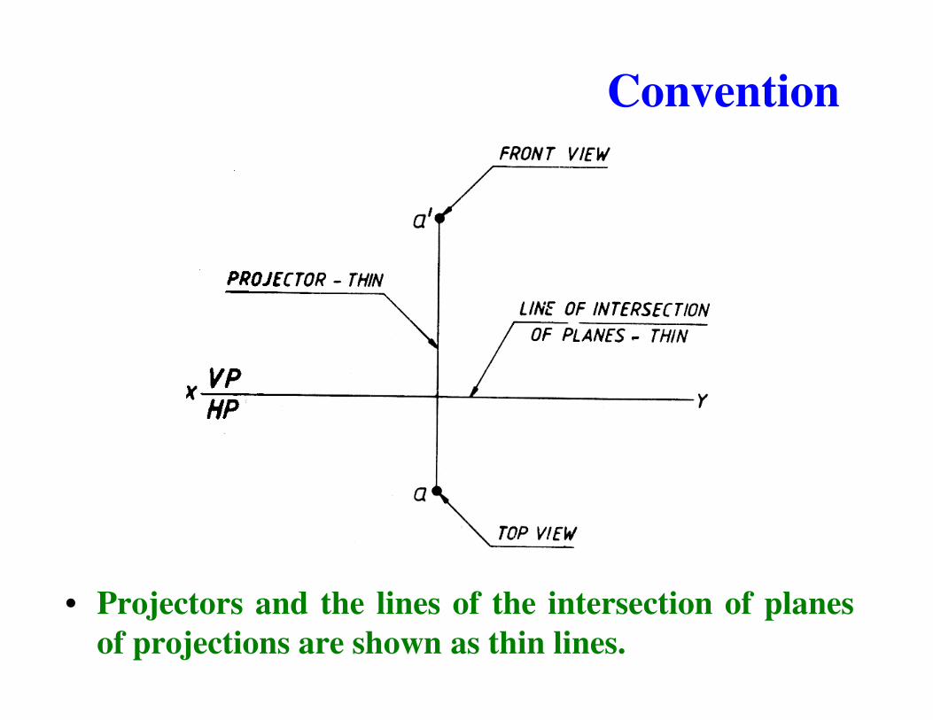
• Top views are represented by only small letters eg. a.
• Their front views are conventionally represented bysmall letters with dashes eg. a�small letters with dashes eg. a�
• Profile or side views are represented by small letterswith double dashes eg. a��
Convention
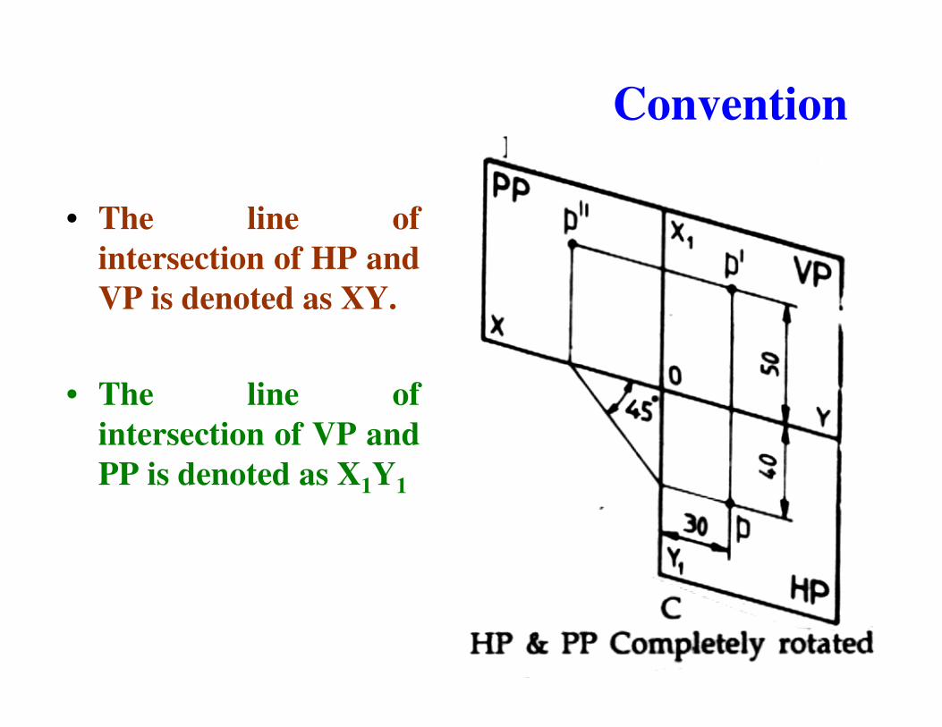
• The line ofintersection of HP andVP is denoted as XY.
• The line ofintersection of VP andPP is denoted as X1Y1
Convention
• Projectors and the lines of the intersection of planesof projections are shown as thin lines.

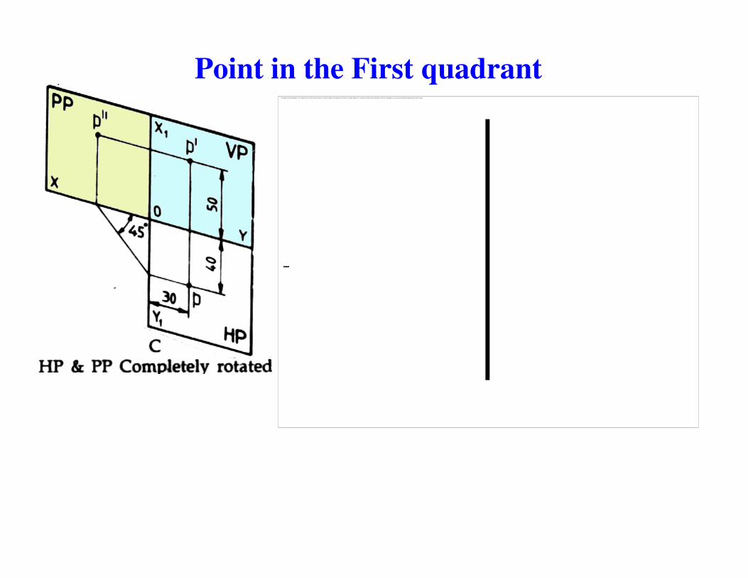
Point in the First quadrantPoint P is 40 mm in front of VP, 50 mm above HP, 30 mm in front of left profile plane (PP)

Point in the First quadrant
Point in the First quadrant�������������� ������������������������������������������������������������������������������������������� ��������������������������������������������������������������������������������������������������������������������������������������� ��������

Point in the First quadrant
Procedure
• Draw a thin horizontalline, XY, to representthe line of intersectionof HP and VP.of HP and VP.
• Draw X1Y1 line torepresent the line ofintersection of VP andPP.
• Draw the Top View (p).• Draw the projector line• Draw the Front View
(p�)
Y1
Point in the First quadrant
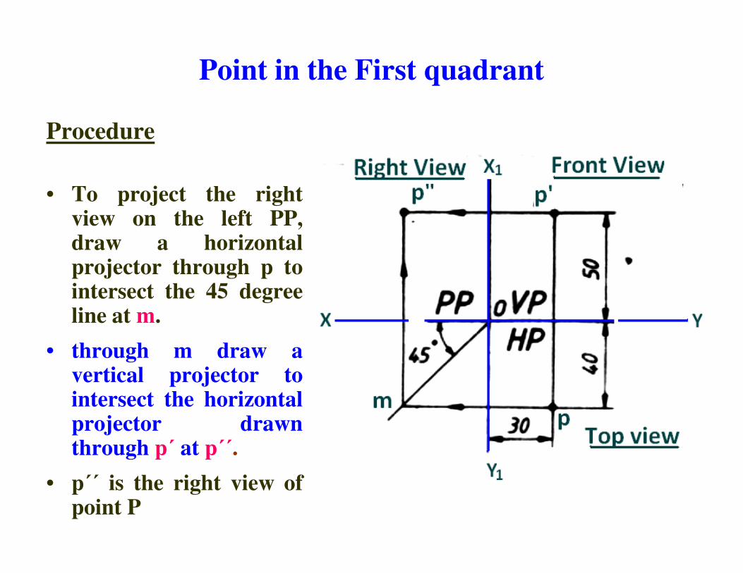
Procedure
• To project the rightview on the left PP,draw a horizontalprojector through p tointersect the 45 degreeintersect the 45 degreeline at m.
• through m draw avertical projector tointersect the horizontalprojector drawnthrough p� at p��.
• p�� is the right view ofpoint P
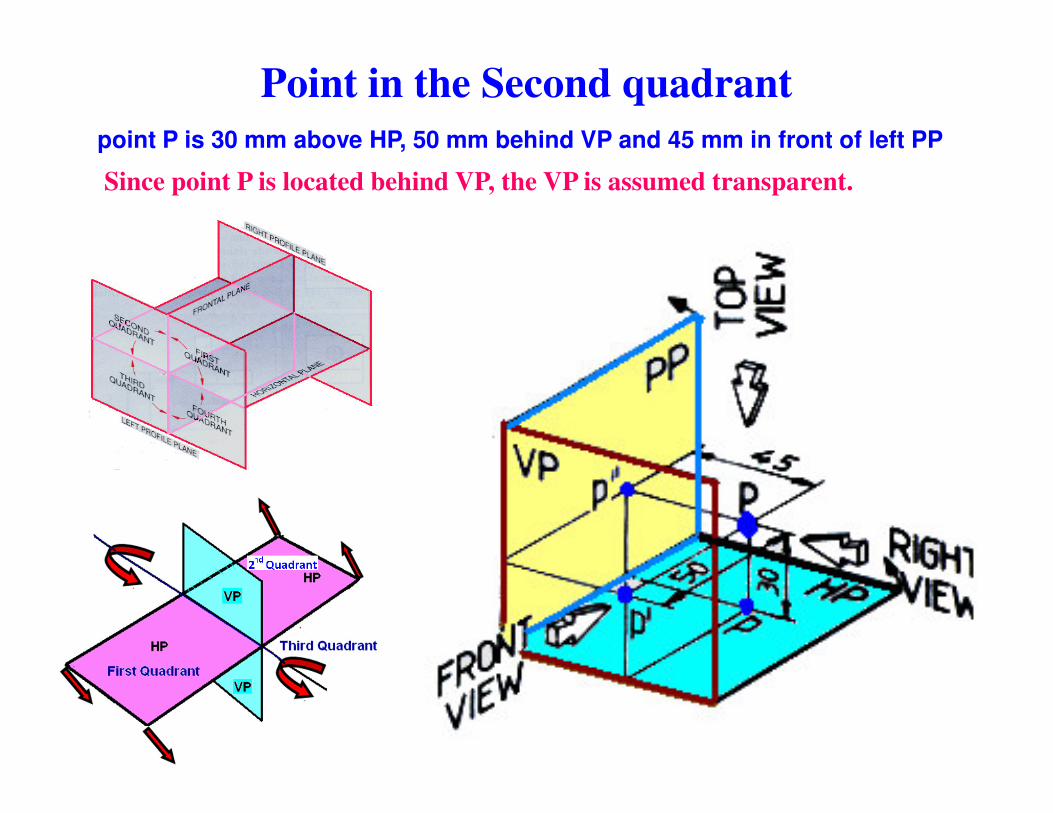
Point in the Second quadrantpoint P is 30 mm above HP, 50 mm behind VP and 45 mm in front of left PP
Since point P is located behind VP, the VP is assumed transparent.
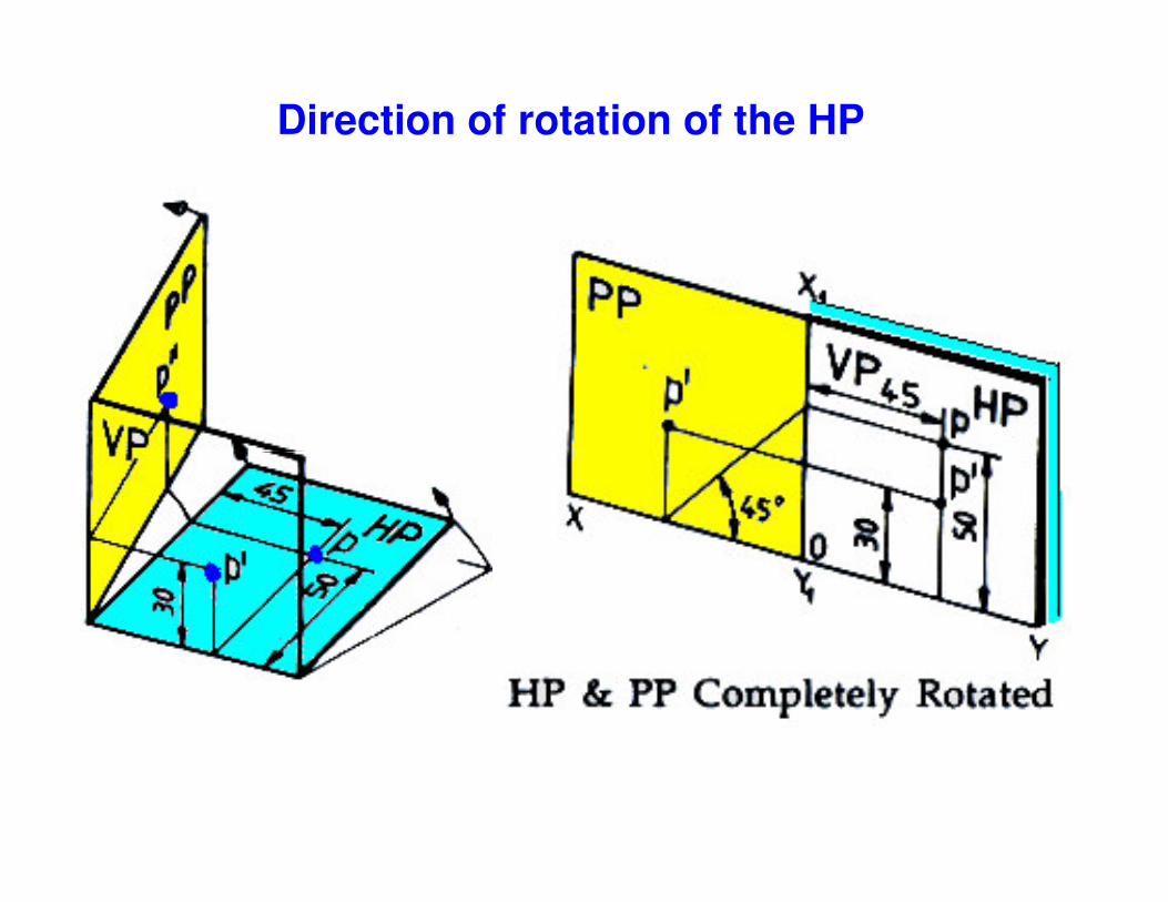
Direction of rotation of the HP

Point in the Second quadrant
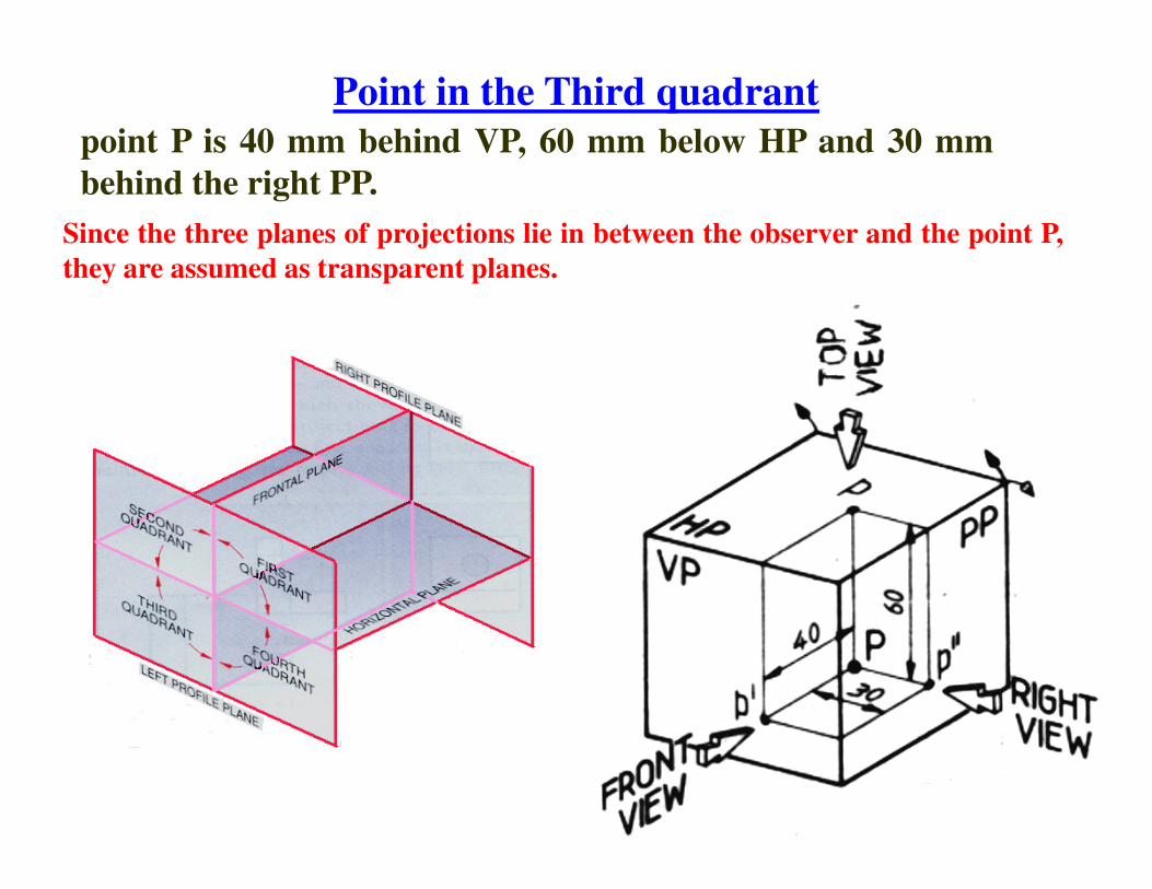
Point in the Third quadrantpoint P is 40 mm behind VP, 60 mm below HP and 30 mmbehind the right PP.
Since the three planes of projections lie in between the observer and the point P,they are assumed as transparent planes.


Point in 3rd quadrant

point P is 60 mm below HP, 50 mm in front of VP, 45 mm infront of the left PP.
Point in the Fourth quadrant


Point in the Fourth quadrant
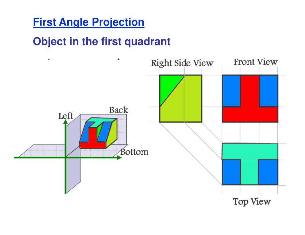
First Angle Projection
Object in the first quadrant

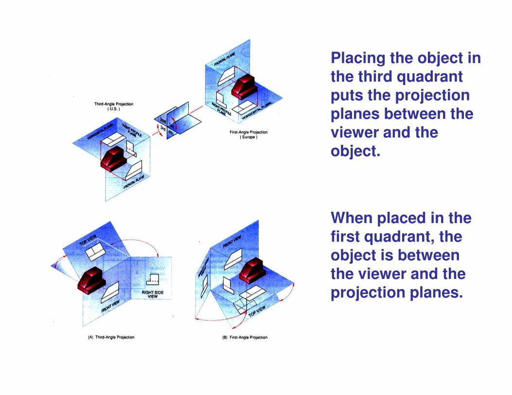
Placing the object in the third quadrant puts the projection planes between the viewer and the object.
When placed in the first quadrant, the object is between the viewer and the projection planes.

Difference between first- and third-angle projections
First angle projection Third-angle projection
Object is kept in the first quadrant. Object is assumed to be kept in the third quadrant.
Object lies between observer and the plane of projection.
Plane of projection lies between the observer and the object.
The plane of projection is assumed to be non-transparent.
The plane of projection is assumed to be transparent.
Front (elevation) view is drawn above Front (elevation) view is drawn Front (elevation) view is drawn above the XY line
Front (elevation) view is drawn below the XY line
Top (plan) view is drawn below the XY line
Top (plan) view is drawn above the XY line
Left view is projected on the right plane and vise versa
Left view is projected on the left plane itself.
Followed in India, European countries Followed in USA

Symbol of projectionThe method of projection used should be indicated in thespace provided for the purpose in the title box of thedrawing sheet. The symbol recommended by BIS is to drawthe two sides of a frustum of a cone placed with its axishorizontal.

Projections of Lines
27
Projections of Lines

Straight lineLocus of a point, which moves linearly theshortest distance between any two given points.
Location of a lineThe location of a line in projection quadrants isThe location of a line in projection quadrants isdescribed by specifying the distances of its endpoints from the VP, HP and PP.
• Parallel to both the planes. • Parallel to one plane and perpendicular to the
other. • Parallel to one plane and inclined to the other. • Inclined to both the planes.
Projection of a line
• Obtained by projecting its end points onplanes of projections and then connectingthe points of projections.the points of projections.
• The projected length and inclination of aline, can be different compared to its truelength and inclination.

Line parallel to a plane

Line inclined to a plane
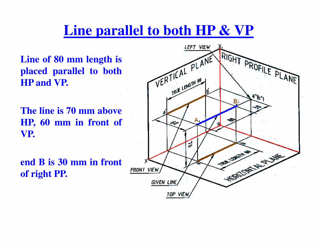
Line parallel to both HP & VP
Line of 80 mm length isplaced parallel to bothHP and VP.
The line is 70 mm aboveHP, 60 mm in front ofHP, 60 mm in front ofVP.
end B is 30 mm in frontof right PP.

Line parallel to both HP & VP…Since the line is parallel to both HPand VP, both the front view a'b' andthe top view ab are in true lengths.
Since the line is perpendicular to theright PP, the left side view of the linewill be a point a��(b��).

Line of 80 mm lengthplaced parallel to VPand perpendicular toHP.
Line perpendicular to HP & parallel to VP
The line is 60 mm infront of VP and 70mm in front of rightPP.
The lower end of theline is 30 mm aboveHP.

Line perpendicular to HP & parallel to VP…
Draw the front view a'b' = 80 mmperpendicular to the XY line, with the lowerend b' lying 30 mm above the XY line.Project the top view of the line which will be apoint a(b) at a distance of 60 mm below XYline.Since the line is 70 mm in front of the right PPdraw the X1Y1 line at a distance of 70 mm ondraw the X1Y1 line at a distance of 70 mm onthe right- side of the front view.Through 0 the point of intersection of XY andX1Y1, lines draw a 45° line.Draw the horizontal projector through a(b) tocut the 45 degree line at m.Draw the horizontal projectors through a' andb' to intersect the vertical projector drawnthrough m at a�� and b��. a��b�� is the left viewof the line AB.
Line parallel to one plane and inclined to Line parallel to one plane and inclined to the other

Line parallel to VP and inclined to HP….
A line AB, 90 mm longis inclined at 30degrees to HP and isparallel to VP.
The line is 80 mm infront of VP.front of VP.
The lower end A is 30mm above HP.
The upper end B is 50mm in front of theright PP.
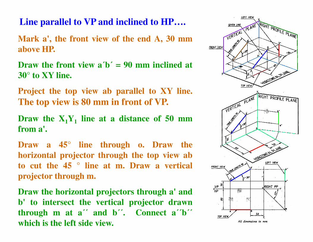
Mark a', the front view of the end A, 30 mmabove HP.
Draw the front view a�b� = 90 mm inclined at30° to XY line.
Project the top view ab parallel to XY line.The top view is 80 mm in front of VP.
Draw the X1Y1 line at a distance of 50 mm
Line parallel to VP and inclined to HP….
Draw the X1Y1 line at a distance of 50 mmfrom a'.
Draw a 45° line through o. Draw thehorizontal projector through the top view abto cut the 45 ° line at m. Draw a verticalprojector through m.
Draw the horizontal projectors through a' andb' to intersect the vertical projector drawnthrough m at a�� and b��. Connect a��b��which is the left side view.
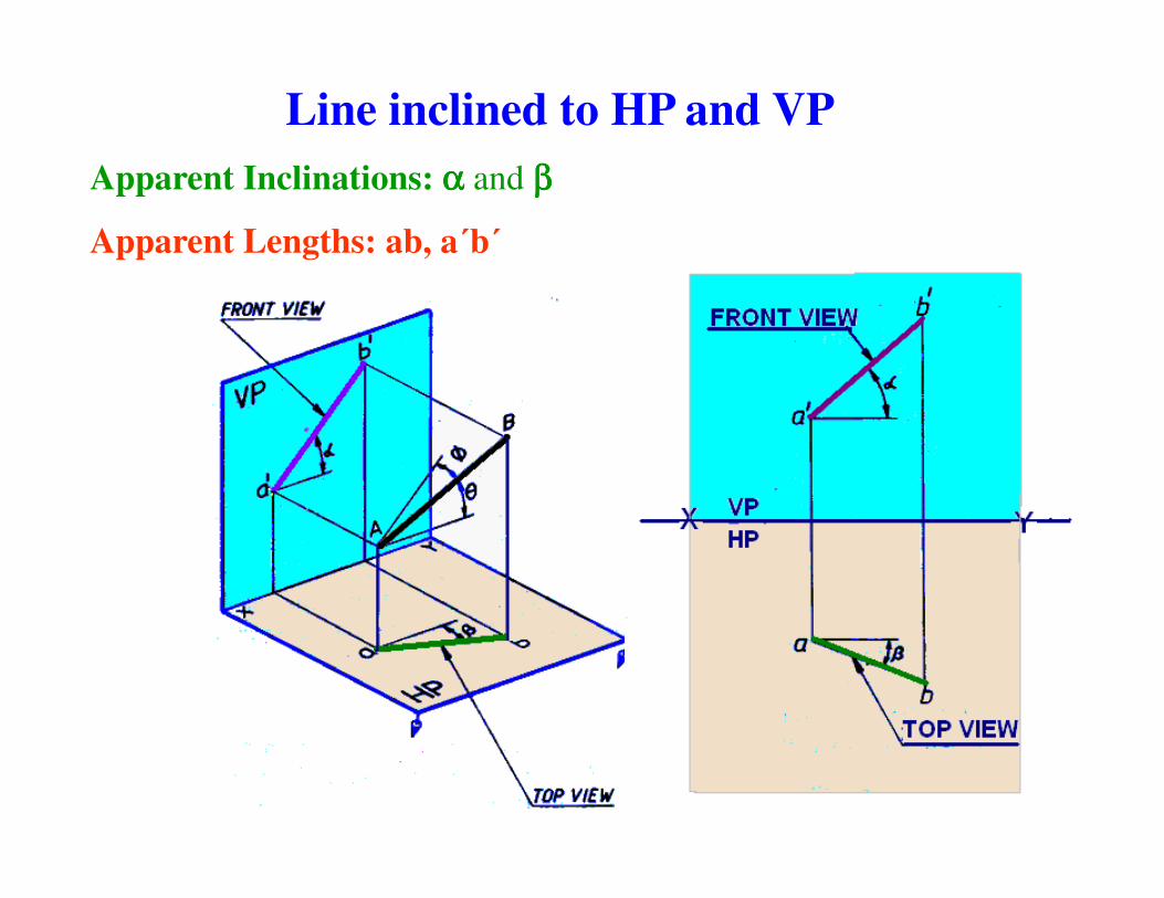
Line inclined to HP and VPApparent Inclinations: αααα and ββββ
Apparent Lengths: ab, a�b�

Line inclined to HP and VP…….
Draw the projections of aline AB inclined to both HPand VP, whose true lengthand true inclinations andlocations of one of the endpoints, say A are given.
Since the line AB is inclinedat θθθθ to HP and φφφφ to VP – itstop view ab and the frontview a�b� are not in truelengths and they are alsonot inclined at angles θθθθ toHP and φφφφ to VP.

Have a nice Day