
MDT693B and MDT694B Open-Loop Piezo...
26
MDT693B and MDT694B Open-Loop Piezo Controllers User Guide
Transcript of MDT693B and MDT694B Open-Loop Piezo...

MDT693B and MDT694B Open-Loop Piezo Controllers User Guide

Open-Loop Piezo Controllers Chapter 1: Warning Symbol Definitions
Rev B, March 27, 2014 Page 2
Table of Contents
Warning Symbol Definitions .............................................................................................. 3 Chapter 1
Safety .................................................................................................................................... 4 Chapter 2
Description ........................................................................................................................... 5 Chapter 3
Setup ..................................................................................................................................... 6 Chapter 4
4.1. Setting AC Line Voltage and Fuses ............................................................................... 6
4.2. Changing Fuses .............................................................................................................. 6
4.3. List of Contents ............................................................................................................... 6
4.4. Initial Setup ...................................................................................................................... 6
Operation .............................................................................................................................. 7 Chapter 5
5.1. MDT693B Front Panel Overview .................................................................................... 7
5.2. MDT693B Back Panel Overview ..................................................................................... 7
5.3. MDT694B Front Panel Overview .................................................................................... 8
5.4. MDT694B Rear Panel Overview ..................................................................................... 8
5.5. Setting the Output Voltage Limit ................................................................................... 9
5.6. Using INT Adjustment Knob ........................................................................................... 9
5.7. Using EXT Input BNC .................................................................................................... 10
5.8. Master Scan Control (MDT693B Only) ......................................................................... 10
Bandwidth Performance ....................................................................................................12 Chapter 6
6.1. Low-Pass Filter .............................................................................................................. 12
6.2. Output Current Limit ..................................................................................................... 12
Remote Communications ..................................................................................................14 Chapter 7
7.1. Installing USB Drivers ................................................................................................... 14
7.2. Command-Line Interface .............................................................................................. 14
7.3. Keywords (Commands and Queries) .......................................................................... 15
Specifications .....................................................................................................................17 Chapter 8
Mechanical Drawings .........................................................................................................19 Chapter 9
9.1. MDT693B Mechanical Drawing .................................................................................... 19
9.2. MDT694B Mechanical Drawing .................................................................................... 19
Troubleshooting .................................................................................................................20 Chapter 10
Warranty ..............................................................................................................................21 Chapter 11
Regulatory ...........................................................................................................................22 Chapter 12
Certifications and Compliance .........................................................................................23 Chapter 13
Thorlabs Worldwide Contacts ..........................................................................................25 Chapter 14

Open-Loop Piezo Controllers Chapter 1: Warning Symbol Definitions
Rev B, March 27, 2014 Page 3
Warning Symbol Definitions Chapter 1Below is a list of warning symbols you may encounter in this manual or on your device.
Symbol Description
Direct Current
Alternating Current
Both Direct and Alternating Current
Earth Ground Terminal
Protective Conductor Terminal
Frame or Chassis Terminal
Equipotentiality
On (Supply)
Off (Supply)
In Position of a Bi-Stable Push Control
Out Position of a Bi-Stable Push Control
Caution: Risk of Electric Shock
Caution: Hot Surface
Caution: Risk of Danger
Warning: Laser Radiation
Caution: Spinning Blades May Cause Harm

Open-Loop Piezo Controllers Chapter 2: Safety
Rev B, March 27, 2014 Page 4
Safety Chapter 2All statements regarding safety of operation and technical data in this instruction manual will only apply when the unit is operated correctly.
SHOCK WARNING
HIGH VOLTAGE To avoid electrical shock and before applying power to your MDT693B or MDT694B system, make sure that the protective conductor of the 3-conductor mains power cord is correctly connected to
the protective earth contact of the socket outlet!
Improper grounding can cause electric shock resulting in severe injury or even death.
Do not operate without the cover installed. Refer servicing to qualified personnel.
WARNING – HIGH VOLTAGE OUTPUTS
The MDT693B and MDT694B can produce hazardous voltages and currents. Use CAUTION when operating the MDT693B or MDT694B and handling the piezo actuators! The piezo elements are
electrical capacitors capable of storing electrical energy over long periods of time. Besides storing charge from the MDT693B or MDT694B, the piezo can accumulate static charge over time due to
varying storage temperature and/or mechanical loads. To safely discharge a piezo, connect it to the MDT693B or MDT694B and set the output voltage to 0 volts.
WARNING
This unit must not be operated in explosive environments.
ATTENTION
Do not obstruct the air ventilation slots in the housing or fan exhaust.
WARNING
Before applying power to your MDT693B or MDT694B system, make sure that the protective conductor of the 3-conductor mains power cord is correctly connected to the protective earth
contact of the socket outlet! Improper grounding can cause electric shock resulting in severe injury or even death.
With the exception of the mains fuses, there are no user-serviceable parts in this product.
This device can only be returned when packed into the complete original packaging, including all foam packing inserts. If necessary, ask for a replacement package.
Mobile telephones, cellular phones, or other radio transmitters are not to be used within the range of three meters of this unit since the electromagnetic field intensity may exceed the maximum allowed disturbance values according to EN50082-1.

Open-Loop Piezo Controllers Chapter 3: Description
Rev B, March 27, 2014 Page 5
Description Chapter 3The MDT693B and MDT694B are precision, low-noise, low-drift, high-voltage controllers for piezo actuators. They provide both local and remote control of piezo drive voltages. The MDT694B supports one channel, while the MDT693B supports up to three channels. They are well suited for single-axis and multiple-axis piezo stages, such as Thorlabs’ MAX312D Three-Axis NanoMax Stage and PE4 Piezoelectric Actuator. Typical applications include remote alignment of single-mode fiber couplers, high-resolution translation, microscopy, and remote positioning.
The intelligent-speed-control potentiometers on the front panel allow for precise setting of the output voltage over the full operating range. This fine control takes full advantage of the inherently high resolution of the piezo element. The MDT693B three-channel controller provides independent controls for each channel.
The drive voltage can also be controlled externally through a USB interface or by applying an analog voltage (0 to 10 V) to the EXT BNC input on the front panel. This voltage is summed with the manual control voltage and multiplied by a gain of 15 V/V. = ( ) + (15 ) The external control voltage can be supplied by any stable voltage source, including function generators, DAC outputs, or DC supplies. In addition, the external voltage can be used as part of a feedback loop for automated alignment systems. Since the external input voltage is summed with either the manual or the USB voltage setting, the manual/USB control can be used for offset adjustments without having to re-adjust the external voltage source.
The MDT693B and MDT694B include a voltage limit switch on the rear panel to select the operating voltage range and gain for the unit. Each unit is shipped with the voltage limit set for 0 – 75 V (Gain = 7.5 V/V) operation and may be adjusted by the user to provide 0 – 100 V (Gain = 10 V/V) or 0 – 150 V (Gain = 15 V/V) operation.
The Master Scan feature on the MDT693B allows all three channels to be controlled by one manual adjuster or one external control signal. In this mode, each channel can be precisely adjusted by an offset voltage (INT control knob for each axis) and by a gain adjustment (SCAN TRIM adjustment for each channel). The gain adjustment allows the output for each channel to be amplified from 80 to 120% of the master control signal.
The MDT693B and MDT694B include 4-digit LED readouts for displaying real-time output voltages of all channels.
These controllers contain a universal power supply. At the time of order, a power cord specific to the region from which your order originates will be included in the box. Should you need a power cord for a different region, please contact your local Thorlabs tech support.

Open-Loop Piezo Controllers Chapter 4: Setup
Rev B, March 27, 2014 Page 6
Setup Chapter 4
4.1. Setting AC Line Voltage and Fuses
The MDT693B and MDT694B piezo controllers are shipped configured for 100 to 240 VAC operation. There is no end-user adjustment of the line voltage. Simply select the correct AC line cord for their geographic location.
4.2. Changing Fuses
To change the power fuse, perform the following steps:
1. Remove the AC line cord if it is connected to the unit.
2. Locate the fuse tray directly below the AC line cord connection on the rear panel of the unit.
3. Carefully use a flat blade screwdriver to open the fuse tray.
4. Remove the existing fuse and install the appropriate fuse (600 mA for the MDT693B, 500 mA for the MDT694B). The replacement fuse must be a 5 mm x 20 mm, 250 VAC Type T Fuse (IEC 60127-2/III, low breaking capacity, slow blow).
5. Push the fuse tray back into place, making sure that it snaps and seats correctly.
6. Connect the appropriate line cord into the AC receptacle and plug the unit in.
4.3. List of Contents
1. MDT693B or MDT694B Controller
2. BNC to SMC Adapter (3 Included with MDT693B, 1 Included with MDT694B)
3. USB Type A to Type B Cable
4. Power Cord (Determined by the Region the Order was Placed From)
5. Operating Manual
4.4. Initial Setup
1. Carefully unpack the controller and accessories. If any of the items appear damaged or missing, do not use the controller. Contact your local Thorlabs tech support for assistance.
2. Make sure the POWER switch located on the front panel is in the OFF position.
3. Plug the female end of the provided AC line cord into the AC input receptacle on the rear of the unit. Plug the male end into a properly grounded AC socket.
4. Select the appropriate output voltage limit on the rear panel. The user can choose from 75 V (Gain = 7.5 V/V), 100 V (Gain = 10 V/V), or 150 V (Gain = 15 V/V) limits.
This switch should only be adjusted while the piezo(s) are disconnected or when the unit is off.
5. Connect the piezo device to the controller output(s). Do not connect piezo devices to the unit while the unit is on.
6. Turn the POWER switch to the ON position.
7. Push and turn the INT control knob to adjust the piezo output voltage. For more advanced controls such as the external input, master scan controls, or USB operation, please see the Table of Contents for the appropriate section of this manual.

Open-Loop Piezo Controllers Chapter 5: Operation
Rev B, March 27, 2014 Page 7
Operation Chapter 5
5.1. MDT693B Front Panel Overview
5.2. MDT693B Back Panel Overview
7-Segment LED 4 Digits
INT Control Knob Voltage Adjustment
Scan TrimGain
Adjuster 80% - 120%
Master EX T InputModulation Input
0 – 10 V
Enable Switch/LED Enables Master Scan
LED On When Enabled
Power Switch Turns Unit On and Off
Master INTMaster
Voltage Adjust
EXT Input Modulation Input 0 – 10 V
AC Input IEC320
Connector
FanFan with Guard
ModelSerial
Number
Voltage Limit Switch
Sets Output Voltage Limit
Communication USB 2.0 HV Output
3 Channel Output CAUTION: High
Voltage

Open-Loop Piezo Controllers Chapter 5: Operation
Rev B, March 27, 2014 Page 8
5.3. MDT694B Front Panel Overview
5.4. MDT694B Rear Panel Overview
7-Segment LED4 Digits
INT Control Knob Voltage
Adjustment
Power Switch
Turns Unit On and Off
EXT Input Modulation Input 0 – 10 V
AC Input IEC320 Connector
Fan Fan with Guard
ModelSerial
Number
Voltage Limit Switch Sets Output
Voltage Limit
Communication USB 2.0
HV Output 1 Channel Output CAUTION: High Voltage

Open-Loop Piezo Controllers Chapter 5: Operation
Rev B, March 27, 2014 Page 9
5.5. Setting the Output Voltage Limit
The MDT693B and MDT694B include a voltage limit switch on the rear panel that can be used to limit the maximum output voltage to 75 V, 100 V, or 150 V. The lower limit is intended for lower-drive-voltage piezos. Thorlabs ships the controllers to operate at the 75 V limit by default. However, it can be easily adjusted, as described below:
1. Determine the maximum allowable voltage for your piezo element (VPIEZO). We recommend the following settings:
a. Use the 150 V limit when VPIEZO > 150 V.
b. Use the 100 V limit when 150 V > VPIEZO > 100 V.
c. Use the 75 V limit when 100 V > VPIEZO > 75 V.
2. Power off the MDT693B or MDT694B and disconnect the piezo(s).
3. Locate the Voltage Limit switch on the rear panel of the MDT693B or MDT694B.
4. Adjust the switch to the desired limit setting determined in Step 1.
5. Turn the controller on. The onboard micro controller will automatically configure the controller to the appropriate settings. The gain of the EXT input BNC connector(s) will vary depending on the gain setting. For the 150 V limit, the gain is 15 V/V; for the 100 V setting, the gain is 10 V/V; and for the 75 V setting, the gain is 7.5 V/V.
5.6. Using INT Adjustment Knob
The INT adjustment knobs manually control the output voltages for each channel from 0 V to 150 V. This can be thought of as a DC offset voltage, since it is summed with the external control voltage (up to a maximum control voltage of 10 V). Note that changing the voltage through USB commands overrides the INT knob.
All adjustment knobs include a lockout feature to prevent accidental adjustment. To adjust the voltage setting, the knob must first be pushed in to unlock it. On the corresponding display, the right-most decimal point will blink after the knob is pushed in, indicating that it is ready for adjustment. To lock the setting, press the knob in again. The knob will automatically relock after 30 seconds of no activity.
The manual adjustment knobs are auto scaling: Adjusting the knob slowly will adjust the output at the highest resolution, and adjusting the knob quickly will make larger voltage adjustments.
Follow the procedure described on the next page for operation in this mode.
1. Attach a piezo to one of the high voltage output connectors on the rear panel of the MDT693B or the front panel of the MDT694B.
Note: The BNC center conductor is positive and the shield is at ground potential. Be certain to match piezo polarity to the connector since most piezo elements will be permanently damaged if connected backwards.
2. Turn the power switch (located on the front panel) to the ON position. The digital displays should begin displaying the output voltage settings. The factory default output setting is 0 V. The unit recalls the previous output state when it is powered on.
3. Set all the output voltages to 0 V by pushing in the control knob and rotating the knob counter-clockwise. The right-most decimal point will blink after the knob is pushed in, indicating that the setting can be adjusted. After 30 seconds of no activity, the display will stop blinking.
4. Adjust the INT knob for each channel until the desired voltages are met.

Open-Loop Piezo Controllers Chapter 5: Operation
Rev B, March 27, 2014 Page 10
5.7. Using EXT Input BNC
The EXT input on the MDT693B and MDT694B is designed to allow the user to modulate the output voltage or for use as feedback with positioning systems. Examples of connections for this input include D/A systems, strain gauges with support electronics, and function generators. The external control voltage is summed with either the INT control knob or the USB voltage setting (changing the voltage through USB will override the INT knob), up to a maximum control voltage of 10 V. To use this feature, follow the steps below.
1. Attach a piezo to one of the high voltage output connectors on the rear panel of the MDT693B or the front panel of the MDT694B.
Note: The BNC center conductor is positive and the shield is at ground potential. Be certain to match piezo polarity to the connector since most piezo elements will be permanently damaged if connected backwards.
2. Turn the power switch to the ON position.
3. Set all the output voltages to 0 V by pushing in the control knob and rotating the knob counter-clockwise. The right-most decimal point will blink after the knob is pushed in, indicating that the setting can be adjusted. After 30 seconds of no activity, the display will stop blinking.
4. Connect an analog input signal (AC or DC), with a voltage between 0 V and 10 V, to the EXT input BNC connector(s). The output for each channel will follow the EXT input voltage with a gain of 7.5 V/V, 10 V/V, or 15 V/V, depending upon the output voltage limit (see Section 5.5, page 9).
Note: Do not place a negative voltage on the EXT input BNC connector. The MDT693B and MDT694B include reverse protection diodes on the EXT inputs, designed to prevent the piezo output from going negative. Presenting negative voltages for long periods of time will damage these diodes and affect the operation of the unit.
5. For sinusoidal and ramp signals, calculate the output current and verify that it will not exceed the maximum current rating of 60 mA. A piezo acts like a capacitor; therefore the output current is a function of the change in voltage divided by the change in time. The MDT693B and MDT694B both have an output-current-limiting circuit to prevent damage to the unit, but the output sinusoid will be distorted.
5.8. Master Scan Control (MDT693B Only)
The Master Scan feature allows all three channels to be controlled by one manual adjuster or one external control signal. Each channel has an independent gain adjustment (SCAN TRIM) that allows the user to compensate for differences between each piezo. The output of each channel is summed with the INT control knobs to provide a different DC offset for each channel.
The Master Scan mode is especially useful for three-axis mounts such as the MAX312D. The SCAN TRIM gain controls and the INT knobs allow the user to precisely tune each output separately, while the MASTER SCAN INT and MASTER SCAN EXT controls adjust all channels simultaneously.
Enable Button
The ENABLE button located on the front panel (see Section 5.1, page 7) is used to enable and disable Master Scan mode. The EXT in for each channel will be disabled and replaced by the master scan EXT signal.
Enable LED
The enable LED, located directly above the ENABLE button, will light when Master Scan mode is activated.
Master Scan EXT
An analog voltage between 0 V and 10 V can be applied to this input to control all three channels over a voltage range of 0 V to 75 V, 0 V to 100 V, or 0 V to 150 V. This input will be summed with the MASTER SCAN INT and the individual INT knobs for each channel, up to a maximum control voltage of 10 V. The MASTER SCAN EXT input is only active when Master Scan mode is active (i.e., the enable LED must be lit). Note that the individual EXT in for each channel is disabled when Master Scan mode is active.

Open-Loop Piezo Controllers Chapter 5: Operation
Rev B, March 27, 2014 Page 11
Master Scan INT
The MASTER SCAN INT knob allows adjustment of all three channels over the full operating range of 0 V to 75 V, 0 V to 100 V, or 0 V to 150 V. This input will be summed with the MASTER SCAN EXT and the individual INT knobs for each channel, up to a maximum control voltage of 10 V. The MASTER SCAN INT knob will only be active when Master Scan mode is active (i.e., the enable LED must be lit).
Master Scan Trim
The SCAN TRIM adjusters scale the signals provided by the MASTER SCAN INT and MASTER SCAN EXT knobs over a range from 80% to 120% on a per-channel basis. This helps compensate for differences in reactance from one piezo to another. The SCAN TRIM adjusters are only active when Master Scan mode is active (i.e., the enable LED must be lit).
Note: The 100% mark is halfway through the adjustment range of the SCAN TRIM potentiometer. To approximately set the SCAN TRIM to 100%, zero the pot by turning it counterclockwise as far as possible (a maximum of four turns). Then adjust the pot clockwise by two turns.
To precisely set the SCAN TRIM to 100%, follow this procedure:
• Adjust all of the INT control knobs counterclockwise as far as possible.
• Disconnect any EXT input connections.
• Adjust all SCAN TRIM pots counterclockwise by a minimum of four turns.
• Apply a 5 V DC voltage source to the MASTER SCAN EXT input.
• Adjust the SCAN TRIM pots clockwise until their displays read 75 V (assuming the voltage limit is set to 150 V).

Open-Loop Piezo Controllers Chapter 6: Bandwidth Performance
Rev B, March 27, 2014 Page 12
Bandwidth Performance Chapter 6The MDT693B and MDT694B are precision, low-noise, low-drift, high-voltage amplifiers designed specifically for driving piezo actuators. There are two limitations that need to be considered. Since piezoelectric crystals can be modeled as capacitors, it is easy to predict their dynamic performance using a basic set of equations as described below.
6.1. Low-Pass Filter
Since the piezo can be modeled most accurately as a capacitor, the piezo will create a low-pass filter with the output impedance of the driver. For both the MDT693B and MDT694B, the output impedance is specified as 150 Ω, 1 nF.
= 1(2 ) Where, = +
For example, consider connecting a piezo with a 1.6 μF capacitance to the MDT693B. Using the output impedances given in the specification section (see page 17):
= 12 (100 )(1nF + 1.6μF) = 994
6.2. Output Current Limit
The output current limit also needs to be considered when determining system performance. Since the piezo is electrically equivalent to a capacitor (CPIEZO), the charge rate (∆V/∆t) needs to be considered. The max current for the MDT693B and MDT694B is 60 mA (IOUT).
= ∆∆
The output current requirements depend upon how quickly the piezo needs to be charged, not the voltage applied to it. Below are some common waveforms and their calculations.

Open-Loop Piezo Controllers Chapter 6: Bandwidth Performance
Rev B, March 27, 2014 Page 13
Linear Ramp Signal = ∆∆
∆ = (∆ )
Triangle Wave = 2 ∆∆
∆ = (∆ )
= 1∆
Sinusoid Wave = cos( ) ( ) = 2
= 2
Where = sin( ) and = 2
For all equations above, = +

Open-Loop Piezo Controllers Chapter 7: Remote Communications
Rev B, March 27, 2014 Page 14
Remote Communications Chapter 7
7.1. Installing USB Drivers
Prior to running the command-line interface, the USB drivers must be installed. To install the drivers the user must have administrative rights on the computer, also depending on the operating system used you may need to right click on the “CD-Starter2.exe” application located on the CD and choose the “Run as Administrator” menu option. The MDT693B and MDT694B must not be connected to the PC while installing the drivers. Insert the CD that was supplied with your unit into your PC. From the dialog box that is displayed, select the Install Drivers button. If the dialog box is not displayed, browse to the CD in Windows and run CD_Started.exe. Follow the onscreen prompts to install the driver. After the driver is installed, attach the MDT693B or MDT694B to the PC and power it on. Your PC will then detect the new hardware and will prompt you when the installation is complete.
7.2. Command-Line Interface
Once the USB drivers have been installed, the unit connected to the PC, and the power turned on, configure the terminal emulator as follows:
• Baud Rate = 115.2 kb/s
• Data Bits = 8
• Parity = None
• Stop Bits = 1
• Flow Control = None
If the connection is correct you will see the following after pressing the “Enter” key.
!
The basic structure of the interface is a keyword followed by either an equals sign “=” or a question mark “?”. The “=” or “?” will determine if the string is a command or a query. All strings (commands and queries) must be terminated by a carriage return (CR) or a line feed (LF) or any combination of a carriage return and a line feed or pressing the ENTER key on the computer.
The command structure is as follows:
Keyword = argument (Command Terminator)
Where “keyword” defines the function and “argument” is a numerical value followed by any valid command terminator. A valid command terminator is a carriage return (CR), a line feed (LF) or any combination of a carriage return and line feed. See listing below.
The query structure is a follows:
Keyword? (Command Terminator)
The “keyword” defines the function and the question mark (?) indicates a query. The query is terminated by any valid command terminator. A valid command terminator is a carriage return (CR), a line feed (LF) or any combination of a carriage return and line feed. See listing below.
There are a few exceptions to this which are noted below, also noted are unique shortcut keys.
The prompt symbol “<” will appear on power up and after a command is accepted by the system indicating it is ready to receive another command line.

Open-Loop Piezo Controllers Chapter 7: Remote Communications
Rev B, March 27, 2014 Page 15
7.3. Keywords (Commands and Queries)
The following list shows all available commands and queries, and summarizes their functions for the MDT693B:
Commanda Syntaxb Description
Get Commands ? List the available commands. Product Information id? Returns the product header and firmware version Restore Default Settings restore Restores default factory settings Get Echo Command Value echo? Returns echo status
Set Echo Command echo=n Sets Echo mode. When the echo mode is on the command parameters will be returned, or echoed back, to the communication program. (Values: 1 = enable; 0 = disable)
Limit Switch Setting vlimit? Returns output voltage limit setting. (75V = 0; 100V = 1; 150V = 2) Get Display Intensity intensity? Returns the display intensity Set Display Intensity intensity=n Set the Display Intensity (0-15). Set All Voltages allvoltage=n Sets all outputs to desired voltage. Get Master Scan Enable msenable? Returns the state of the Master Scan enable. Set Master Scan Enable msenable=n Sets Master Scan mode. (Values: 1 = enable; 0 = disable) Get Master Scan Voltage msvoltage? Reads and Returns the master scan voltage
Set Master Scan Voltage msvoltage=n Sets a master scan voltage that adds to the x, y, and z axis voltages. (Sets master scan DAC)
Read X-Axis Voltage xvoltage? Reads and returns the X axis output voltage. Set X-Axis Voltage xvoltage=n Set the output voltage for the X axis. Read Y-Axis Voltage yvoltage? Reads and returns the Y axis output voltage. Set Y-Axis Voltage yvoltage=n Set the output voltage for the Y axis. Read Z-Axis Voltage zvoltage? Reads and returns the Z axis output voltage. Set Z-Axis Voltage zvoltage=n Set the output voltage for the Z axis. Read Min. X-Axis Voltage ymin? Reads the minimum output voltage limit for X axis. Set Min. X-Axis Voltage xmin=n Sets the minimum output voltage limit for X axis. Read Min. Y-Axis Voltage ymin? Reads the minimum output voltage limit for Y axis. Set Min. Y-Axis Voltage ymin=n Sets the minimum output voltage limit for Y axis. Read Min. Z-Axis Voltage zmin? Reads the minimum output voltage limit for Z axis. Set Min. Z-Axis Voltage zmin=n Sets the minimum output voltage limit for Z axis. Read Max. X-Axis Voltage xmax? Reads and returns the maximum output voltage limit for X axis. Set Max. X-Axis Voltage xmax=n Sets the maximum output voltage limit for X axis. Read Max. Y-Axis Voltage ymax? Reads and returns the maximum output voltage limit for Y axis. Set Max. Y-Axis Voltage ymax=n Sets the maximum output voltage limit for Y axis. Read Max. Z-Axis Voltage zmax? Reads and returns the maximum output voltage limit for Z axis. Set Max. Z-Axis Voltage zmax=n Sets the maximum output voltage limit for Z axis. Get voltage adjustment resolution dacstep? Reads the current step resolution
Set voltage adjustment resolution dacstep=n Sets the step resolution when using up/down arrow keys (n = 1 to 1000)
Increment Voltage Up arrow Increments the current channel voltage by resolution set in dacsteps (Adjustment range: 0 to 65536, limited by factory calibrated limit)
Decrement Voltage Down arrow Decrements the current channel voltage by resolution set in dacsteps (Adjustment range: 0 to 65536, limited by factory calibrated limit)
Decrease channel Left arrow Decreases channel setting and returns value (order: master scan if enabled, z axis, y axis, x axis)
Increase channel Right arrow Increases channel setting and returns value (order: master scan if enabled, z axis, y axis, x axis)
Get Friendly Name friendly? Returns the friendly name. Set Friendly Name friendly=string Sets the friendly name. Get Serial Number serial? Returns the serial number. Get Compatibility Mode cm? Returns compatibility mode (0 = disabled, 1 = enabled) Set Compatibility Mode cm=n Sets compatibility mode (0 = disable, 1 = enable) Get Rotary Mode rotarymode? Returns the rotary controls mode. (0 = Default, 1 = 10 turn pot, 2 = fine) Set Rotary Mode rotarymode= Sets the rotary controls mode. (0 = Default, 1 = 10 turn pot, 2 = fine)
a. All commands and queries are not case sensitive. b. The MDT693B will recognize MDT693A commands.

Open-Loop Piezo Controllers Chapter 7: Remote Communications
Rev B, March 27, 2014 Page 16
The following list shows all available commands and queries, and summarizes their functions for the MDT694B:
Commanda Syntaxb Description
Get Commands ? List the available commands. Product Information id? Returns the product header and firmware version Restore Default Settings restore Restores default factory settings Get Echo Command Value echo? Returns echo status
Set Echo Command echo=n Sets Echo mode. When the echo mode is on the command parameters will be returned, or echoed back, to the communication program. (Values: 1 = enable; 0 = disable)
Limit Switch Setting vlimit? Returns output voltage limit setting. (75V = 0; 100V = 1; 150V = 2) Get Display Intensity intensity? Returns the display intensity Set Display Intensity intensity=n Set the Display Intensity (0-15). Read X-Axis Voltage xvoltage? Returns the X axis output voltage. Set X-Axis Voltage xvoltage=n Set the output voltage for the X axis. Read Min. X-Axis Voltage Xmin? Returns the minimum output voltage limit for X axis. Set Min. X-Axis Voltage xmin=n Sets the minimum output voltage limit for X axis. Read System Min. Voltage sysmin? Returns the minimum output voltage for the system. Set System Min. Voltage sysmin=n Sets the minimum output voltage for the system. Read Max. X-Axis Voltage Xmax? Returns the maximum output voltage limit for X axis. Set Max. X-Axis Voltage xmax=n Sets the maximum output voltage limit for X axis. Read System Max. Voltage sysmax? Returns the maximum output voltage for the system. Set System Max. Voltage sysmax=n Sets the maximum output voltage for the system. Get voltage adjustment resolution dacstep? Reads the current step resolution
Set voltage adjustment resolution dacstep=n Sets the step resolution when using up/down arrow keys (n = 1 to 1000)
Increment Voltage Up arrow Increments the current channel voltage by resolution set in dacsteps (Adjustment range: 0 to 65536, limited by factory calibrated limit)
Decrement Voltage Down arrow Decrements the current channel voltage by resolution set in dacsteps (Adjustment range: 0 to 65536, limited by factory calibrated limit)
Get Friendly Name friendly? Returns the friendly name. Set Friendly Name friendly=string Sets the friendly name. Get Serial Number serial? Returns the serial number. Get Compatibility Mode cm? Returns compatibility mode (0 = disabled, 1 = enabled) Set Compatibility Mode cm=n Sets compatibility mode (0 = disable, 1 = enable) Get Rotary Mode rotarymode? Returns the rotary controls mode. (0 = default, 1 = 10 turn pot, 2 = fine) Set Rotary Mode rotarymode= Sets the rotary controls mode. (0 = default, 1 = 10 turn pot, 2 = fine)
a. All commands and queries are not case sensitive. b. The MDT694B will recognize MDT694A commands.
If the keyword, format, or argument is incorrect or out of range, the unit will return an exclamation point. The function is determined by the value set with the mode command in the above table.
In addition to the above commands, there is also special functionality added to the arrow keys of the computer’s keyboard.

Open-Loop Piezo Controllers Chapter 8: Specifications
Rev B, March 27, 2014 Page 17
Specifications Chapter 8All specifications are for both MDT693B and MDT694B unless noted explicitly.
General Features AC Input Voltage 100 - 240 VAC AC Input Frequency 50 – 60 Hz AC Input Power (Max)
MDT693B 60 VA MDT694B 30 VA
Operating Temperature 10 to 40 °C Fuse Type IEC60127-2/3 (250 VA, Slow Blow Type ‘T’) Fuse Size 5 mm x 20 mm Fuse Rating
MDT693B 600 mA MDT694B 500 mA
Performance Input/Output Specs
External Input Voltage 0 – 10 V External Input Impedance 10 kΩ Output Voltage 0 – 75, 0 – 100, or 0 - 150 VDC
(Limit Switch Dependent) Output Current Limit (Max) 60 mA Output Noise 1 1.5 mVrms (~9.9 mVpp) Output Impedance (Max) 150 Ω, 1.0 nF Min Load Impedance 2 2.5 kΩ
Output Voltage Range (Switch Selectable) Voltage Limit Position (75 V) 0 – 75 VDC Voltage Limit Position (100 V) 0 – 100 VDC Voltage Limit Position (150 V) 0 – 150 VDC
External Input Gain Voltage Limit Position (75 V) 7.5 V/V (±5%) Voltage Limit Position (100 V) 10 V/V (±5%) Voltage Limit Position (150 V) 15 V/V (±5%) Scan Trim Gain Adjustment 80% to 120% of Master Scan Ext + Int
Bandwidth (-3 dB) No Load, Small Signal 3 9 kHz No Load, 150 Vpp
4 8.5 kHz 1.4 µF Piezo, 150 Vpp 200 Hz Stability <0.01% over 5 hours
A/D and D/A Performance D/A Resolution 16-Bit / 2.75 mV A/D Resolution 16-Bit / 3.0 mV Communications USB 2.0
1 The MDT693B and MDT694B were tested without an external load connected (1 nF output impedance only). Adding a capacitive load, such as a piezo, will
decrease the noise spec since the capacitance will create a low-pass filter with the output resistance. 2 The Min Load Impedance represents the smallest allowable terminating resistance. Applying lower impedances will cause the short-circuit protection to limit the
output voltage. Continued use in this mode will cause circuit degradation and eventual circuit failure. 3 Assume a ramp function is used. The bandwidth is load-dependent and requires calculation for a more representative number. See Chapter 6, page13 for
details.

Open-Loop Piezo Controllers Chapter 8: Specifications
Rev B, March 27, 2014 Page 18
Connections and Controls Interface Control Optical Encoder with Push Button Display 4-Digit, 7-Segment LED Input Power Connection IEC Connector Input/Output Connectors BNC (Male) Power On Rocker Switch Scan Trim Controls 4-Turn Potentiometer Remote Interface USB Type B
Physical Specifications Display Type 7-Segment LED with 4 Digits Number of Displays
MDT693B 3 MDT694B 1
Display Resolution 0.1 V Number of Channels
MDT693B 3 MDT694B 1
Dimensions MDT693B 12.18" x 4.15" x 8.55" (309.4 x 105.5 x 217.1 mm) MDT694B 6.05" x 3.22" x 12.11" (153.6 x 81.8 x 307.6 mm)
Weight MDT693B 3.02 kg (6.65 lbs) MDT694B 1.93 kg (4.25 lbs)

Open-Loop Piezo Controllers Chapter 9: Mechanical Drawings
Rev B, March 27, 2014 Page 19
Mechanical Drawings Chapter 9
9.1. MDT693B Mechanical Drawing
9.2. MDT694B Mechanical Drawing
4.15"(105.5 mm)
12.18"(309.4 mm)
8.55"(217.1 mm)
2.88"(73.2 mm)
12.11"(307.6 mm)
11.63"(295.4 mm)
3.22"(81.8 mm)
6.05"(153.6 mm)
Open-Loop Piezo Controllers Chapter 10: Troubleshooting
Rev B, March 27, 2014 Page 20
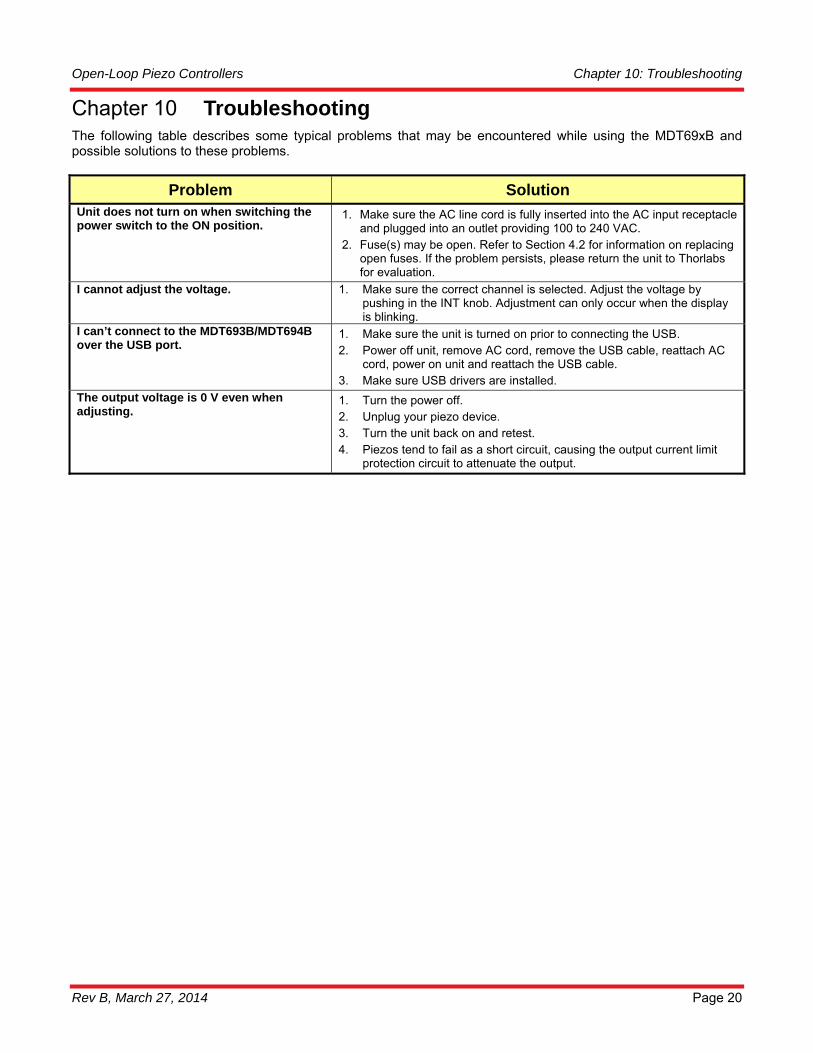
Troubleshooting Chapter 10The following table describes some typical problems that may be encountered while using the MDT69xB and possible solutions to these problems.
Problem Solution Unit does not turn on when switching the power switch to the ON position.
1. Make sure the AC line cord is fully inserted into the AC input receptacle and plugged into an outlet providing 100 to 240 VAC.
2. Fuse(s) may be open. Refer to Section 4.2 for information on replacing open fuses. If the problem persists, please return the unit to Thorlabs for evaluation.
I cannot adjust the voltage. 1. Make sure the correct channel is selected. Adjust the voltage by pushing in the INT knob. Adjustment can only occur when the display is blinking.
I can’t connect to the MDT693B/MDT694B over the USB port.
1. Make sure the unit is turned on prior to connecting the USB. 2. Power off unit, remove AC cord, remove the USB cable, reattach AC
cord, power on unit and reattach the USB cable. 3. Make sure USB drivers are installed.
The output voltage is 0 V even when adjusting.
1. Turn the power off. 2. Unplug your piezo device. 3. Turn the unit back on and retest. 4. Piezos tend to fail as a short circuit, causing the output current limit
protection circuit to attenuate the output.

Open-Loop Piezo Controllers Chapter 11: Warranty
Rev B, March 27, 2014 Page 21
Warranty Chapter 11Thorlabs, Inc. warrants the material and production of the MDT69xB Piezo Controller for a period of 24 months from the date of shipment. During this warranty period, Thorlabs, Inc. will repair or exchange any units found to be defective in material or workmanship.
For warranty repairs or service, the unit must be returned to Thorlabs, Inc. or one of our worldwide offices. All returns must be accompanied by a Returned Material Authorization (RMA) number issued by Thorlabs. The customer is responsible for all costs incurred to ship the unit back to Thorlabs; in the case of warranty repairs, Thorlabs will cover the cost of shipment back to the customer.
In the case of shipments from outside of the United States, duties, taxes etc. shall be the responsibility of the customer.
Thorlabs, Inc. warrants all firmware and software used for the MDT69xB to operate fault-free, provided they are used in accordance with the requirements stated in this manual. However, Thorlabs does not warrant a fault-free operation for special applications.
Thorlabs, Inc. does not guarantee that this manual is error free and reserves the right to change this manual, the specifications, or the data of the described unit at any time, without notice.
Thorlabs, Inc. is not liable for any incidental damage caused by failure of this unit.
This warranty does not cover errors in operation, defects, or damage caused by the use of software not supplied by Thorlabs, modifications or misuse, or damage caused if the unit is used outside the operating parameters specified in this manual.
This warranty does not cover failure due to incorrectly connected heater and/or sensor elements, or failure of heater and/or sensor elements.
ATTENTION
The MDT69xB is not intended for use in medical and/or life support situations.
! !

Open-Loop Piezo Controllers Chapter 12: Regulatory
Rev B, March 27, 2014 Page 22
Regulatory Chapter 12As required by the WEEE (Waste Electrical and Electronic Equipment Directive) of the European Community and the corresponding national laws, Thorlabs offers all end users in the EC the possibility to return “end of life” units without incurring disposal charges.
• This offer is valid for Thorlabs electrical and electronic equipment: • Sold after August 13, 2005 • Marked correspondingly with the crossed out “wheelie bin” logo (see right) • Sold to a company or institute within the EC • Currently owned by a company or institute within the EC • Still complete, not disassembled and not contaminated
As the WEEE directive applies to self-contained operational electrical and electronic products, this end of life take back service does not refer to other Thorlabs products, such as:
• Pure OEM products, that means assemblies to be built into a unit by the user (e. g. OEM laser driver cards)
• Components • Mechanics and optics • Left over parts of units disassembled by the user (PCB’s, housings etc.).
If you wish to return a Thorlabs unit for waste recovery, please contact Thorlabs or your nearest dealer for further information.
12.1. Waste Treatment is Your Own Responsibility
If you do not return an “end of life” unit to Thorlabs, you must hand it to a company specialized in waste recovery. Do not dispose of the unit in a litter bin or at a public waste disposal site.
12.2. Ecological Background
It is well known that WEEE pollutes the environment by releasing toxic products during decomposition. The aim of the European RoHS directive is to reduce the content of toxic substances in electronic products in the future.
The intent of the WEEE directive is to enforce the recycling of WEEE. A controlled recycling of end of life products will thereby avoid negative impacts on the environment.
Wheelie Bin Logo

Open-Loop Piezo Controllers Chapter 13: Certifications and Compliance
Rev B, March 27, 2014 Page 23
Certifications and Compliance Chapter 13

Open-Loop Piezo Controllers Chapter 13: Certifications and Compliance
Rev B, March 27, 2014 Page 24

Open-Loop Piezo Controllers Chapter 14: Thorlabs Worldwide Contacts
Rev B, March 27, 2014 Page 25
Thorlabs Worldwide Contacts Chapter 14
USA, Canada, and South America Thorlabs, Inc. 56 Sparta Avenue Newton, NJ 07860 USA Tel: 973-300-3000 Fax: 973-300-3600 www.thorlabs.com www.thorlabs.us (West Coast) Email: [email protected] Support: [email protected]
UK and Ireland Thorlabs Ltd. 1 Saint Thomas Place, Ely Cambridgeshire CB7 4EX Great Britain Tel: +44 (0)1353-654440 Fax: +44 (0)1353-654444 www.thorlabs.com Email: [email protected] Support: [email protected]
Europe Thorlabs GmbH Hans-Böckler-Str. 6 85221 Dachau Germany Tel: +49-(0)8131-5956-0 Fax: +49-(0)8131-5956-99 www.thorlabs.de Email: [email protected]
Scandinavia Thorlabs Sweden AB Mölndalsvägen 3 412 63 Göteborg Sweden Tel: +46-31-733-30-00 Fax: +46-31-703-40-45 www.thorlabs.com Email: [email protected]
France Thorlabs SAS 109, rue des Côtes 78600 Maisons-Laffitte France Tel: +33 (0) 970 444 844 Fax: +33 (0) 825 744 800 www.thorlabs.com Email: [email protected]
Brazil Thorlabs Vendas de Fotônicos Ltda. Rua Riachuelo, 171 São Carlos, SP 13560-110 Brazil Tel: +55-16-3413 7062 Fax: +55-16-3413 7064 www.thorlabs.com Email: [email protected]
Japan Thorlabs Japan, Inc. Higashi-Ikebukuro Q Building, 1F 2-23-2, Higashi-Ikebukuro, Toshima-ku, Tokyo 170-0013 Japan Tel: +81-3-5979-8889 Fax: +81-3-5979-7285 www.thorlabs.jp Email: [email protected]
China Thorlabs China Room A101, No. 100 Lane 2891, South Qilianshan Road Putuo District Shanghai China Tel: +86 (0) 21-60561122 Fax: +86 (0)21-32513480 www.thorlabschina.cn Email: [email protected]

www.thorlabs.com


![[DESIGN] Piezo-Piezo to Pie](https://static.fdocuments.us/doc/165x107/5571f8bb49795991698df909/design-piezo-piezo-to-pie.jpg)