
MDG-12
23
Section 1 Section 2 Section 3 Section 4 Secti-{)n 5 Section 6 GU+nz rOB THE cowsnucy:row or n+CT+ON w:rupgs No MDG12 -FILE REFERENCE: C82/3465 DATE OF ISSUE:lS/6/92 CONTENTS Scope Winding Ropes Winding Suspension Equipment Shaft Equipment Winding Machinery Testing for Compliance Part A Inspection Part B Testing Appendix I Head Rope Factor of Safety Appendix II Explanatory Notes
description
regs
Transcript of MDG-12
Section 1
Section 2
Section 3
Section 4
Secti-)n 5
Section 6
GU+nz rOB THE cowsnucyrow or n+CT+ON wrupgs
No MDG12
-FILE REFERENCE C823465
DATE OF ISSUElS692
CONTENTS
Scope
Winding Ropes
Winding Suspension Equipment
Shaft Equipment
Winding Machinery
Testing for Compliance
Part A Inspection Part B Testing
Appendix I Head Rope Factor of SafetyAppendix II Explanatory Notes
Guide for the Cqnstrnctjon of Frjctiqn Winders
Prefage
This Guide sets out minimum requirements for the design installation and use of winding equipment installed in shafts for the conveyance of men and materials where the driving force is transmitted to the hoisting rope or ropes by friction between the rope drum and rope
Manual semi-automatic or automatic control may be adopted
The guide has been based on an orginal document entitled Requirements for the use of Friction Winders which was pr~pared in 1971 This guide has been modified to incorporate the provisions of the Coal Mines Regulation Act 1982 and its Regulations together with the references to the current Australian Standards middot for shaft winding equipment and attachments Testing requirements have experience gained
also been included which has been over a period of 20 years of
based the a
on ppr
the oval
testing process
LJROBERTS SENIOR INSPECTOR OF MECHANICAL ENGINEERING
Page 2 of 22
Guide for the Construction gf Frjctiqo Wjnders
1
11
12
13
14
-15
16
17
SCOPE
Clause 7 of the Coal Mines Regulation Act (Shafts and Roadways Underground -Mines) Regulation 1984 requires that a mechanically operated winding apparatus or mechanically operated rope haulage apparatus used at a mine for transporting persons through any shaft or roadway be approved by the Chief Inspector
Clause 9 (1) ofmiddot the Coal- Mines Regulation (Shafts and Roadways Underground Mines) Regulation 1984 requ~res that conveyances used at a coal mine for transporting persons through a shaft be of a type whichmiddot has been approved for the purpose by the Chief Inspector
This guide is intended to assist manufacturers of Friction Winders by indicating the design parameters which will be considered in the assessment for
middotapproval of equipment as referred to in 1 1 and 12
The following definitions apply
friction winder means a shaft winding system in which conveyances are raised and lowered by means of friction between a head rope or head ropes and a driving sheave or sheaves
conveyance includes all types of equipment attached to a friction winding systems in which persons are transported middot
The guide does not generally_ give quantitive information as it is not intended to restrict innovative design Where specific values or test procedures are required in addition to or as alternatives to those included in this document advice should be sought from Inspectors of Mechanical Engineering Coal Mining Inspectorate and Engineering Branch of the Department of Mineral Resources
IIQIlL shall and should
(a) shall means that the requirement if required under existing legisldetermined by the Chief Inspector
is ation
mandator
ory as_
(b) should means recommended
Unless otherwise speci-fied the appropriate Australian Standards shall apply
Where reference is made to a design standard the current published version shall be utilised
Page 3 middot-middot of 22
Guide for the Construction of Frjctiqn Winders
This guide does not in any way negate the requirements of the Coal Mines Regulation Act 671982 nor the
and Occupational Health and Safety AC~ 1983 No 20 84 ing 19 Formal snbrnjssjons fqr apprqyal age ons l 91 Approval applications should be supported by the ief followingshy
18
(A) A credible Risk Assessment report which and effectively identifies middotassesses and controls 84 hazards relating to the safety of persons for associated with the operation maintenance and ype testing of the complete Winding System ief
Note (1) In general the risk assessment will cover situations or areas where there are no codes
of or standards or where variations are required
or middot (2) This document may be used as an aid to
assist in identification of hazards but should not solely be relied on for that purpose Sources of other relevant
in information such as that contained within of the First and Second Reports of the UK
a Health and Safety Executive entitled Safety of Manriding in Mines should be utilised as should details of accidents or dangerous
1ed occurrences which have occurred with 1re existing winders
~rs
(B) A brief statement of compliance variationmiddot or Lve reason for non compliance with each item cct mentioned in this guide ~st
as A marked up and signed copy of this middotguide may be lt used to indicate the status of the design al ng (C) Results of tests and a statement of compliance
with all requirements in accordance with Australian or other relevant standards
(D) Any further information requested within this Jry guide or as considered to be appropriate in as supporting the application
(E) Full details pertaining to the type of control for winder operation ie manual semiautomatic or automatic middot~middotmiddot
an middot 1 92 Documentation covering electrical aspects as required
by the Department of Mineral Resourcesmiddot Applicants he Guide to obtaining an approva-l from the Chief
Inspector of Coal Mines or an Accredited Assess2ng Authority shy
Page 4 of 22 22
Guj de for the Cpnstructj on of Frj ct iop Winders
All electrical apparatus shall comply with the requirements of the -Coal Mines Regulation Act 67]982 subsequent Regulations and relevant Australian Standards
110 Whilst primarily intended middot for use with new friction winders the guidelines where applicable will be used as an integral part of the assessment process for applications for approval of variations to existing approved friction winders
2 wntpplusmnBG ROPES
21 General All ropes used in the construction of the friction winder system ie head balance guide and rubbing shall comply with the requirements of
(a) Coal Mines Regulation (Shafts and Roadways Underground Mines) Regulation 1984 and
(b) The relevant sections of Australian Standard AS3569-1989 Steel Wire Ropes as applicable for winder installations
22 Rope Factors of Safety
221 Head Ropes The factor of safety for head ropes shall be in accordance with Appendix 1 - Notice of Specification Bead Ropes for Friction Winders
222 Qther Ropes The factor of safety for all other ropes such as balance guide and rubbing ropes shall be in accordance with the Coal Mines Regulation (Shafts and Roadways - Underground Mines) Regulation 1984
23 Galvanised ropes should be used in shafts where the quantity or chemical content of the moisture or water would cause serious corrosion to an ungalvanised rope
24 The use of any form of rope dressing which may reduce the design coefficient of friction bet_ween the head rope and the drive sheave is not permitted
25 The winder should be designed for multiple head ropes
Page 5 of 22
Guide for the Constrpctj QD of Frier ion Winders
the 3 l82 ian 31
ion tsed for ing
ion 32 ing
ard for
in 4 1
41
as in 42
ind
he 43 er
ICe 44 ad
WINQING SUSPENSION EQUIPMENT
Material
The material used in the attachments and suspension accordance with Australian Underground Mining - Winding Part 1 General Requirements
-manufacture of rope equipment shall be in
Standard AS3637 1-1989 Suspension Equipment shy
Note Alternative materials- may be acceptable providing that it can be demonstrated that they have equivalent chemical and physical properties
Components
Rope attachments -and suspension equipment shall be in accordance with the relevant sections of the following Partsmiddot of Australian Standard AS3637-1989 Underground Mining- Winding Suspension Equipment Part 3 Rope Cappings Part 4 Drawbars and Connecting Links Part 5 Rope Swivels and Swivel Hooks Part 6 Shackles and Chains middot
Note The use of detaching hooks is prohibited
SQFT EOUIPMINT
Headframes shall be in accordance with Australian Standard AS37855-1991 Underground Mining Shaft Equipment- PartS Headframes
Conveyances shall be in accordance with Australian Standard AS3785 41992 Underground Mining Shaft Equipment -Part 4 Conveyances for Vertical Shafts
Each Friction Winder Conveyance shall be of a type which is compatible with the friction winding system and has been approved
Sheaves shall be in accordance with Australian Standard AS37857-1993 Underground Mining Shaft Equipment - Part 7 Sheaves except as specified in Clause 51
Guides and rubbing ropes for conveyances shall be in accOrdance with Australian Standard AS3785 6-1992 Underground Mining - Shaft Equipment - Part 6 Guides and Rubbing Ropes middotfor Conveyances
22 Page 6 of 22
45
Gujde for the Cqnstructjon qf Frjctjon Wjpders
46 Arresting systems to limit the effects of an overwinc shall at least be in accordance with Australiar Standard AS37852-1991 Underground Mining Shaft Equipment Part 2 middot~Friction Winding Arrest ins Systems
Note AS3785 Parts 1 and 3 for Drum Winding Overwinc Safety Catch Systems and Grippers do not apply tc friction winder installations
47 Access
In addition to the provisions for access incorporatec in AS3585 5 - Headframes the following access is required
471 All platforms walkways and ladders shall comply with Australian Standard AS 1657-1985 Fixed Platforms Walkways Stairways and Ladders
472 Provision shall be made at all working levels for personnel to safely embark and disembark from a conveyance
473 Provision shall be made in the head frame and shaft sump by way of suitable pl-atforms and ladders for access to an overwound cage and safe access for personnel leaving an overwound conveyance
474 The space between the lowest stopping point and the shaft sump shall be equipped with ladders or other suitable means of access to permit proper inspection and maintenance of that part of the shaft The access facilities shall be effectively enclosed
475 Access landings acceptable to the authorities approved to conduct non-destructive testing of head and balance ropes over their full length shall be provided
48 A signal line should be provided in the shaft for transmission of data to the surface for recording on testing equipment in the winder engine room
49 The shaft sump shall be designed so that the ingress of water debris or other material will be limited to an extent that will prevent the balance ropes or weights from contacting such water debris or other material
410 Any building or structure on the top of the shaft shall comply with the requirements of Clause 31 of the Coal Mines Regulation (Fire Control Underground Mines) Regulation 1984
411 Keps or chairing devices shall not be provided in the shaft except with the written approval of the Chief Inspector
Page 7 of 22
bullind Lian 1aft ing
-rind to
1ted is
rith ms
for a
taft for for
the her ion ess
gtved nee
for on
ess to or
her
aft the und
the ief
5
51
51 (i)
Rope Size
Up to 31 75mm diabull
From 31 75mm to 4445mm dia
Above 4445mm dia
51(ii)
51(iii)
51 (iv)
51 (v)
52
52(i)
52 (ii)
There shall tower such winder and bring the conveyance attachment
be provided in the shaft headframe or devices as will remove the power from the
by automatic application of the brakes winding sheaves to rest before any cage skip counterweight or rope
reaches any permanent obstruction to its passage Such devices shall be in addition to the automatic contrivance required by Clause 56
SheayeaRppe Cgpfiqurgtign
The ratio of winding sheave to be less than the followingshy
Stranded
The
No Reverse Bending
701
801
851
Bending
801
901
951
coefficient of friction between the rope treads on the driving sheave and the winding ropes shall be such that there will be no slip under normal out-of-balance loading acceleration and retardation Such coefficient shall not be less than 02
The same
T~e less
grooves in a multi-grooved sheave shall be the sheave diameter
diameter of any deflecting sheaves shall be not than 0 9 times
driving sheave
The angle of contact shall be sufficient the sheaves
rope diameter shall not
Locked Coil
No Reverse Bending Bending
851 951
951 1051
1001 1101
the diameter of the corresponding
of the rope on deflecting sheaves to prevent the rope slipping on
Unless otherwise approved -in writing by the Chief Inspector
In raising or speed shall not
In raising or speed shall not
lowering exceed 20
lowering exceed 15
material the maximum winding metres per second
persons the maximum winding metres permiddot second
Page 8 of 22 22
- Gnj de for the Constrncentt iop of Frj ct ign Wj nders
52(iii)
53
53 (i)
53(ii)
53(iii)
53(iv)
5 3 (v)
53 (vi)
53 (vii)
5 3 (viii)
53(ix)
53(x)
53(xi)
53(xii)
53 (xiii)
In raising or lowering persons the maximum approach speed to the shaft top and bottom shall not exceed 3 5 metres per second
Every friction winding engine shall be provided with two or more mechanical brake systems each of which
Howsoever applied shall act directly on the driving sheave
Shall be designed adjusted and maintained to safely stop and hold the conveyance cage or skip under all conditions of loading direction of travel and speed
Will be capable of producing a braking torque of not less than two and a half times the maximum static torque which will be applied to the winding sheave by the normal load
Ismiddot sufficient to cause retardation under worst conditions of rtot less than 1 msec2 when winding personnel and 05 msec2 when winding material
Will result in a retardation rate of not more than 35 msec2 when winding personnel
When applied by any means other than those set out in sub-paragraph (ii) above will produce a braking torque less than will cause the winding rope to slip unduly on the winding sheave
Howsoever applied will not produce a braking torque which will cause a dangerous rate of retardation
Can be applied irrespective of the action of any safety device that may act to apply the brake or brakes
Will be automatically applied when the supply of power to thewinder fails
Will be automatically applied when the pressure of any fluid or other medium used as a means of controlling the brake falls below the value necessary to produce the braking torque required by sub-paragraph (iii) of this condition
Shall be provided with a steel tension member between individual soleplates ofmiddotmiddot brake shoes
Will be automatically applied if ah earth fault occurs in the control circuit
Will be automatically applied if the relative speed between the ropes and the sheave periphery differs by 15 metres per second or more
Page 9 of 22
h 5
h
Ly Ll
Jt Lc JY
3t
5
Ln le Ly
1y Jr
~n
s
Guide fqr
53 (xiv)
53 (XV)
53 (xvi)
54
55
56
5 6 ( i)
56(ii)
56(iii)
57
58
59
the Construction of Frictjqo Winders
The brake system components shall be designed against fatigue failure
Where a system of electrical braking is included its use shall not be prevented by any emergency stop and
The winder shall be provided with a device to automatically apply the brake before the brake becomes worn sufficiently to effect its safe operation
Every winder shall be provided with a stop switch so designed and constructed as to ensure that when it is operated the brakes will be applied and all power except that required for electrical braking will be removed from the winder
Every winder shall be provided with depth and speed indicators driven from a sheave shaft and so placed as to be readily seen
Every winder shall be provided with an effective automatic contrivance to prevent over-winding and over-speeding so constructed asshy
To prevent the descending conveyance or skip from exceeding a speed 15 greater middot than the maximum designed speed and to ensure progressive reduction of speed during retardation to prevent overwinding at excessive speed under any condition of loading
To control the movement of the ascending cage or skip to prevent danger to any person therein and
To stop the winder when the conveyance carrying personnel travels beyond the brace
Every winder shall be provided with a device which will automatically synchronise the depth indicator and the automatic contrivance required by middotClause 56 with the position of the cage or skip in the shaft Such synchronising adjustment shall take place only while the brakes are applied and the winder is not winding
When a winder is being used for the carriage of persons and its operation is under push button control from within the cage it shall be incapable of motion unless all shaft _doors and cage or skip doorsmiddot in connection with that winder are properly closed All limit switches 11sed formiddot this purpose shall be series duplicated middotmiddot
Any device provided to permit backing out of an overwind position shall respond to mariual control only and sh3ll not permitmiddot backirig out in a wrong direction
Page 10 of 22 22
Guide for the Constructjon gf Frjctjon Winders
510
511
512
513
514
515
516
517
Where lt is arranged that the winder may be controlled by more than one method (manual push-button andor other) the device for selecting any control method shall be available only to authorised persons
Push-button controls located at any landing shall only be accessible to a person inside a conveyance when the conveyance door is open
Push-button controls shall be effective from one point only until that operation is completed All automatic controls shall fail to safety
Where it is arranged for push-button control of the winder from within a conveyance a stop button shall be provided which when operated will cause the winder to stop
In every case where the winder is situated in the middotheadframe or tower of a shaft effective precautions shall be taken to prevent any flammable liquid used in connection with the winder or any apparatus installed in the headframe or tower from entering the shaft
In every such case where the winder is not under supervision an automatic fire suppression system with the capacity of extinguishing any fire which may break out in the winder room and with a suitable alarm system shall be provided
Provision to be made in the winder control circuit for recording apparatus to monitor the winding cycle and record maximum winding speed acceleration and retardation rates and position of the conveyance (s) cage(s) or skip(s) in the shaft
These provisions will be required for commissioning tests and regular inservice testing throughout the life of the installation
Production winding installations to be provided with interlocks to indicate and control the winding cycle to pre-set parameters when the winding equipment is being middotused to transport personnel bull
Page 11 of 22
61
TJiSTplusmnNG IOB -CQMPL+ltNCii
Part A - rnapeqtign
ed or od
y e rmiddotmiddot
nt Jbull
611 ~
ic
he
11 612he
he 62 ns in 621 ed
er th ak rm
or nd nd )
ng he
th 622 le is
The following matters are required to be included in the manufacturers program for inspection prior to commencing operational commissioning tests
D~sjgn
Statements to be supplied by equipment manufacturers setting out the design standard adopted for structural components of headframe shaft landings machinery and tower foundations etc
Brake systems designed against fatigue using reserve factor concept
Details of Equipment
Shafts
(a) Overtravel limits to be duplicated (b) Mechanical brake dump valve (c) Arrestors for conveyances and counterweight
specifications required (d) Drop back catches - design details required (e) Keps chairing devices or grippers - not allowed
except with approval of Chief Inspector of Coal Mines shy
(f) Conveyance cage or counterweight detaching - not allowed
(g) Provision for drainage of sump (h) Provision of access to landings and enclosures (i) Provision of access )andings for non-destructive
rope testing (j) No flammable fluids to enter shaft from tower
winding engine room (k) Automatic fire extinguishing equipment in tower
Machinery
(a) Deflecting sheaves not less than 0 9 times rope drum diameter
(b) Rope drum tread diamet_er to rope diameter ratio should be between 70 to 1 and 110 to 1 depending on rope type and size
(c) Coefficient of friction between the rope and rope drum not less than 02
(d) Rope grooves on multi--rope drums to be identical diameters
(e) Type of rope _groove tread material and specification
(f) middotDrawing details for enginemiddot compone~ts and control components to be checked
Page 12 of 22 22
Guide for the Constructjgn of Frjctjon Winders
623
6 2 4
625
6 2 6
-
Mechanical Brakes
(a) Two or more brake assemblies to be provided anc applied directly to the winding drum
(b) Steel tension members between the brake sole plates - post brakes
(c) Brake wear limits and brake released limits to be fitted
(d) Provision for independent application (e) Provision of depth and speed indicators ir
winding engine room (f) Provision for winder operation in eurovent of power
failure - emergency only (g) Method of synchronising cage position controlmiddotanc
depth indicator of automatic contrivance - middotOnly with winder stationary and brakes applied
Control Systems
(a) Overwind back out by manual control only (b) Landing push buttons not accessible from
conveyance with doors closed (c) Conveyance and landing door interlocks to be
duplicated in series (d) Control from one push button point at a time (e) Conveyance controls to be provided with stop
button middot (f) Conveyance to be ventilated
Ropes and Rope Attachments
(a) Manufacturers test reports for all rpes used on the installation
(b) Calculations for each rope showing
(i) Maximum load applied to the rope (ii) Factors of safety based on maximum load
and rope breaking loads (iii) Minimum factor of safety as required by
the requirements for use of friction winding equipment
(c) Arrangement drawings for all rope attachments (d) Guide rqpe anchorage andtensioning details (e) Materialmiddot specifications and test certificates for
all attachments
Compliance with Australian Standards
Statements of compliance provided for any relevant item of equipment supplied as an integral part of the winder
~middot
Page 13 of 22
Part B - Tsatinq
The following matters inclusion in the commissioning the winder
m
are anuf
to actu
be rers
considered program
for for
General Inspection
Before commencing a test of the winding installation checks should be made to ensure that the general condition of the winding equipment is satisfactory for the tests to be carried out and that shy
(1) Pivots levers etc on the automatic contrivance are free and appear to be functioning correctly
(2) Brake linings are not unduly worn and brake paths are free of grease and oil and are not in danger of becoming contaminated
(3) Brake posts and brake shoes are properly adjusted to give correct clearance and motion linings are correctly bedded and the brake engine or cylinders are within the limits of their travel Where overtravel and wear switches are fitted these should be checked and operated manually
(4) Winding ropes and winding sheaves rope treads are free from excessive contamination such as dirt
JS grease or water middot on
(5) In the case of AC winding engines the supply voltage is noted
(6) Any rope creep compensating device depth indicator automatic contrivance and cam gear inoad the winding engine house is correctly set relative to the conveyance(s)by
ion 64 Where dynamic testing of a winding engine with an
equivalent man load in one conveyance is carried out it is implicit that the test be repeated with the load changed over to the other conveyance The standard test load should be declared and be equivalent to thefor maximum number of men specified as the manriding load for conveyance at 88 kg per man
For a conveyance and counterweight system the standard test load should be used when testing with reference
65 middotant
to the conveyance but the conveyance should be emptythe when testing with reference to the counterweight
buring testing a person should be stationed at an appropriate safe place in the pit bottom to detect any unusual circumstances which may arise egmiddot fouling of the balance ropes or displacement of the test load
66
Page 14 of 2222
Guide for the Construction of Frictjon Winders
67 It is important that the following points be observed during winding engine testing
(1) The testing engineer should direct and control testing operations and only persons essential to the performance of these operations should be present in the winding engine house
(2) The Mine Mechanical and Electrical Engineers or their nominees should be present and be responsible for control of the winding engine during loading and unloading of the conveyance(s) and when adjustments are being made
(3) The testing engineer should be positioned or provided with means to give clear instructions to the person operating the winding engine and have a clear view of the graph on the recording instrument at the same time
(4) Notwithstanding that the person operating the winding engine will be operating under the instructions of the testing engineer he should be advised to stop the winding engine if he becomes aware of anything that will affect the safety of personnel or equipment
(5) When adjustments are made a check should follow to ensure that they are correct by a safe method before attempting to resume the testing sequence For some adjustments this may involve a brake holding test or a trip at low speed with an ascending load
(6) The testing engineer should ascertain whether rope slip has occurred
A method of detecting rope slip is outlined in Appendix II Clause I
68 oneratjon of Mechanjcal Brakes and Safety Circuit
These tests are designed to ensure that the level of braking torque is adequate and that the safety circuit is functioning properly before tests at speed are made
Before these tests are carried out ensure that the depth indicator and conveyance position are synchronised
Carryout procedure outlined in Appendix II Clause for the detection of rope slip
Page 15 of 22
I
Gnide for the Copstructimiddoton pf Frjctiop Wjpders
bullrved 681 Preliminary test of brake holding power service brake
trol Test 1 A l to i be Winding engines with balance conveyances
Position the empty conveyances near mid-shaft and 3 or apply power torque with the brakes fully on
be gine e (s)
Note maximum value of current applied before the rope drum moves through the brakes
Test JB
or ions Winding engines with conveyance and counterweight
and ding Position the conveyance and counterweight near mid
shaft and with the brakes fully on apply power torque in the direction of maximum out-of-balance load
the the Note the maximum value of current applied before the
mld rope drum moves through the brakes he
the 682 Brake holding test maximum out-of-balance loadshyService Brake
llow Test 2A
3afe ing Winding engines with balanced conveyances re a l an (a) With the standard test load in one of the
conveyances lower the loaded conveyance to near the shaft bottom
her (b) Apply power to raise this conveyance and note
maximum motor current which will hold the load in without the use of brakes
(c) Raise the conveyance several drum turns out of s]Jaft bottom then with the brakes fully on apply motor power in favour of the loaded conveyance up
of to a maximum of 1 5 times the current noted in uit (b) above or until _the rope drum moves through are the brakes whichever first occurs
(d) Note the maximum motor current obtained the are
I
Page 16 of 22 22
Gpide for the Constrnctign gf Frictjgp Wjnders
Test 2B
Winding engines with conveyance and counterweight
(a) Determine maximum out-of-balance condition for the system ie with conveyance loaded or unloaded
(b c d) With the maximum out-of-balance lOad near the shaft bottom proceed as in Test 2A items (b) (c) and (d) above
Note Test 2A and 2B
If the rope drum moves through the brakes before the motor current attains a value of 15 times the current noted in (b) then the brake system is deemed to have failed to comply with design requirements for friction winding engines
683 Application Test - Emergency Brakes
Test 3
Position loaded conveyance near mid-shaft
Release the brakes and allow the out-of-balance load to accelerate the winding engine to approximately half speed trip the safety system by operating the emergency stop device
The brakes should apply automatically
Test 4
Repeat Test 3 at full speed applying power if necessary
During Test 3 and 4 period of application of brakes and initial conveyance speed are to be recorded to allow retardation rates to be determined
Test 5
Where brake operation is dependent on fluid pressure repeat Test 3 and apply brakes by simulated loss of brake operating fluid pressure
Page 17 of 22
for or
the b) 1
the middotent ave ion
cad alf the
if
kes to
ure of
Gni de for the Cqnstruct i-on of Frict jon Wj pders
684 Landing Speed Test
An artificial landing will need middotto be established for one or other of the conveyances during the following tests
Appendix II Clause 2 describes methods of setting up an artificial landing
With the loaded conveyance at the artificial landing mark the winding ropes drum and depth indicator to establish an accurate reference point
Ensure that the automatic contrivance is set for man winding speed
Test 6
Raise the loaded conveyance approximately two (2) drum revolutions above the artificial landing then lower it until an overspeed trip occurs
Test 7
Repeat Test 6 for three increasing trip speeds up to maximum man winding speed starting further above the artificial landing if necessary
Test a
Accelerate the conveyance from normal maximum man winding speed to obtain a trip at the maximum speed permitted by the automatic contrivance just prior to the retardation portion of the trip curve
Check the temperature of the brake path during these middot tests and allow cooling time if necessary
During Tests 6 7 and 8 the following records should be taken where appropriate
(a) Trip speed (b) Distance of trip point from artificial landing (c) Retardation (d) Distance of loaded conveyance from artificial
landing when stopped (e) Maximum landing speed (f) Rope slip or creep
When the above tests are- completed the artificial landing is to be removed (See Appendix II Clause 3)
Page 18 of 22 22
Guide for the CQnst ruct jon qf Fri ct jon Wj nders
69 Windjoq Cycle Control Fuoctjoos
These tests are intended to ensure that windins speeds landing speeds travel limits interlocks anc control points are correctly adjusted
These tests are to be carried out with empt conveyances or balanced conditions in conveyance anc counterweight systems
Test 9
With the conveyance initially at the surface landing apply power and accelerate the conveyance in the dowr direction through the complete cycle to the botton landing
Note reading on the depth indicator at intermediatE and bottom landing~ Complete the wind in the ur direction noting the depth indicator reading when thE
conveyance returns to the surface landing
During Test 9 readings of maximum winding speed commencement of retardation landing approach speec and winding cycle times are to be recorded
Test 10
Overtravel limits
Raise the conveyance slowly above the surface landins in turn through each of the overtravel limits
Note the depth indicator readings at each trip of thE winding engine control circuit
Ensure that when each limit is reset the windins engine cannot be driven in a direction which woulc aggravate the overwind
Test 11
Repeat Test 10 with the cage at the shaft bottom
Page 19 of 2~
~~inti de for the Construction of Frj ctj on Winders
AfPIJmiX X
[Published in Government Gazette No 44 of23rd March 1984] ding (4471) Department of Industrial Relations
and Sydney 23rd March 1984 COAL MINES REGULATION ACT 1982-NOTICE OF SPECIFICATION
Specification 845002 mpty File No M 84-5002
and HEAD ROPES IOR FRICTION WINDERS
IT is hereby notified that the Chief Inspector of Coal Mines for the purposes of the Regulation cited as the Coal Mines
ing Regulation (Shafts and Roadways-Underground Mines) Regulation down 1984 under the Coal Mines Regulation Act 1982 has ttom specified that the factor of safety for head ropes when newly
installed on a friction winder under Clause 13 (2) shall be as indicated below
iate Each set of windLng ropes used to suspend a cage in any up friction winding apparatus shall have a combined factor of
the safety not less middotthan F1 (transport of persons) and F2 (transport of mineral or material) as defined in the followingformulae middot
eed peed 1 Personnel Transportation
For the purposes of the above the factor F is defined as
Il 45(R+C)l F1 = 10 +
d 1 ~ng R(1 + 00051 L05 ) - 135
~
middotwhere the
F1 = the factor of safety (personnel) R = the ratio of the diameter of the winding sheave to
ding diameter of the winding rope ould c = 35 where there is not a nearby deflecting sheave or
43 where there is a nearby deflecting sheave L = the vertical distance in metres between the level of
the top of the highest winding sheave and the level at which the winding ropes meet the suspension gear of the cage when at its lowest position in the shaft
2 Mineral or Material Transportation
For the purposes of the above the factor F2 is defined as
F2 = Fl - 1 0
where
F2 = the factor of safety (mineral or material) F1 = the factor of safety (personnel)
This notice shall take effect on and from 26th March 1984
Page 20 of 22f 22
Guide for the Constructjqp of Frjctjqn Wjnders
M J MUIR Chief Inspector of Coal Mines
Page 21 of 22
_Gnjde fqr the ConstrJJctjop of Frjction Winders
PPENPIX IT - EXPLANATORY NOTES
ClaJJsg 1 - petection of Rope Slip _ A method of detecting rope slip is to mark the rope (s) before
testing with tape at a position which coincides with a mark on the drum and corresponds to a mark on the depth indicator
At any time during testing when it is suspected that rope slip has occurred and always at the completion of testing the
_ relationship of the three marks should be checked
A convenient time for marking and checking for rope slip is when setting and removing an artificial landing
An accumulation of rope creep can be detected by the same method
Clause 2 - sett iDg an Arti fj cial randj ng
Method 1
Where the automatic contrivance is fitted with moveable cam dials for each conveyance
(a) Place the declared test load in one conveyance
(b) Wind the loaded conveyance to the lowest level and stop it at the normal landing position Suitably mark the sliding part of the automatic contrivance cam dial in relation to the non-sliding part Note the clearance between the overwind cam and its roller at the shaft bottom position Wind the conveyance about ten completed drum turns up the shaft loosen the sliding part of the dial and move it bodily complete with the cams to its shaft bottom position The dial should then be made secure and temporary marks put on the ropes depth indicator and drum showing middotthe position of the artificial landing It middotis normal practice to mark the drum relative to a fixed point as a check and to facilitateshyresetting The setting of the overwind switch should then be checked by slowly lowering the loaded conveyance until an overwind trip occurs
Method 2
Fpr Other Automatic Contrjvances
Additional protection should be middotafforded for the loaded conveyance when ascending For this purpose (during middottesting) a limit switch sJ_ould be introduced into the trip circuit and arranged to operate when the required loaded conveyance is at a distance from the highest landing equal to the distance for normal retardation from maximum speed
(a) Place the declared test load in one conveyance
Page 22 of 22f 22
Guide for the Construction of Frjction Winders
(b) Wind the loaded conveyance to the lowest level and stop it at the normal landing position Suitably mark the two halves of the drive coupling nearest to the automatic contrivance relative one to the other and with reference to a fixed point Wind the conveyance about ten completed drum turns up the shaft noting the number of revolutions of the automatic contrivance coupling Uncouple the drive and reset the automatic contrivance bymiddot hand turning back the same number of revolutions to the fixed mark previously made and reconnect the coupling This position may now be regarded as the artificial landing and temporary marks should be made on the ropes depth indicator and drum It is normal practice to mark the drum relative to a fixed point as a check And to facilitate resetting The setting of the overwind switch should be checked by slowly lowering the loaded conveyance until an overwind trip occurs
Clause 3 - Restoration of Normal Landings
These procedures apply to Method 1 and Method 2 respectively of Clause 2
Method 1
The procedure of resetting to the normal landing is as follows
Wind the conveyance to the artificial landing Loosen the sliding part of the dial and turn it until the marks on both the sliding and the non-sliding parts of the dial coincide Secure the two parts together and remove the temporary marks on the ropes depth indicator and drum Wind SLOWLY to the rope creep compensating position and compensate if necessary Check the setting of the dial on the automatic contrivance which refers to the conveyance just tested and if necessary wind this conveyance to the other end of the wind to enable this to be done Test the overwind trips as described in Test 10
Method 2
The procedure for resetting to the normal landing is as follows
Wind the conveyance to the artificial landing uncouple the drive and reset the automatic contrivance by hand until the marks on the two half couplings coincide making sure that the number of revolutions of the automatic contrivance half coupling is the same as that previously noted when setting the artificial landing Reconnect the coupling and remove the temporary marks on the ropes depth indicator drum and coupling Lower the conveyance SLOWLY to the rope creep compensating position and compensate if necessary Check the setting of the dial on the automatic contrivance which refers to the conveyance just test and if necessary wind this conveyance to the other end of the wind to enable this to be done Test the overwind trips as described in Test 10
Page 23 of 22
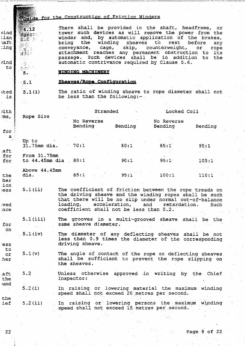


