
MDD Digital AC Servo Motors with Liquid Cooling · MDD Digital AC Servo Motors with Liquid Cooling...
81
MDD Digital AC Servo Motors with Liquid Cooling DOK-MOTOR*-MDD**LIQUID-PRJ1-EN-P Project Planning Manual mannesmann Rexroth engineering Indramat 264700
Transcript of MDD Digital AC Servo Motors with Liquid Cooling · MDD Digital AC Servo Motors with Liquid Cooling...

MDD Digital AC Servo Motorswith Liquid Cooling
DOK-MOTOR*-MDD**LIQUID-PRJ1-EN-P
Project Planning Manual
mannesmannRexroth
engineering
Indramat264700

2• DOK-MOTOR*-MDD**LIQUID-PRJ1-EN-E1,44 • 10.96
About this documentation
Copyright
Validity
Published by
© INDRAMAT GmbH, 1995Copying this document, and giving it to others and the use or communicationof the contents thereof without express authority, are forbidden. Offenders areliable for the payment of damages. All rights are reserved in the event of thegrant of a patent or the registration of a utility model or design (DIN 34-1)
The electronic documentation (E-doc) may be copied as often as needed ifsuch are to be used by the consumer for the purpose intended.
All rights are reserved with respect to the contents of this documentation andthe availability of the product.
INDRAMAT GmbH • Bgm.-Dr.-Nebel-Straße 2 • D-97816 LohrTelephone 09352/40-0 • Tx 689421 • Fax 09352/40-4885Dept. ENA (UW, FS)
Title
Type of documentation
Documenttype
Internal file reference
Reference
Purpose of documen-tation
MDD Digital AC Servo Motors with Liquid Cooling
Project Planning Manual
DOK-MOTOR*-MDD**LIQUID-PRJ1-EN-E1,44 • 10.96
• Mappe 12
• MDDLI-PJ.pdf
• 209-0069-4380-00
This electronic document is based on the hardcopy document with documentdesig.: 209-0069-4380-00 EN/03.95
This documentation serves to
• clarify technical data
• mechanically integrate the motor into the machine
• electrically integrate the motor into the machine
• outline all available options
• specify order details for the motor and connecting accessories
Designation of documentation Release- Commentsup to present edition date
209-0069-4380-00 EN/03.95 Mär./95 First Edition
DOK-MOTOR*-MDD**LIQUID-PRJ1-EN-E1,44 Okt./96 Introduction of document type
Change procedures

3• DOK-MOTOR*-MDD**LIQUID-PRJ1-EN-E1,44 • 10.96
Table of Contents
1. Liquid-cooled MDD servo motors 5
2. General technical information 8
2.1. Environmental conditions .................................................................8
2.2. Motor feedback ................................................................................9
2.3. Mechanical features .......................................................................10
2.4. Electrical features...........................................................................12
2.5. Torque-speed characteristics curves ............................................. 14
3. Technical data 16
3.1. MDD 090 (liquid-cooled) ................................................................163.1.1. MDD 090 motor data .....................................................................163.1.2. MDD 090 torque-speed characteristics curves ............................193.1.3. MDD 090 - shaft load ....................................................................223.1.4. MDD 090 - dimensional data ........................................................243.1.5. MDD 090 - type codes ...................................................................26
3.2. MDD 093 (liquid-cooled) ................................................................273.2.1. MDD 093 - motor data ...................................................................273.2.2. MDD 093 - torque-speed characteristics curves........................... 313.2.3. MDD 093 - shaft load .....................................................................373.2.4. MDD 093 - dimensional data ........................................................383.2.5. MDD 093 - type codes ...................................................................40
3.3. MDD 112 (liquid-cooled).................................................................413.3.1. MDD 112 - motor data ..................................................................413.3.2. Torque-speed characteristics curves for MDD 112 .......................453.3.3 MDD 112 - shaft load .....................................................................513.3.4. MDD 112 - dimensional data ..........................................................523.3.5. MDD 112 - type codes ....................................................................54
3.4. MDD 115 (liquid-cooled).................................................................553.4.1. MDD 115 - motor data ...................................................................553.4.2. Torque-speed characteristics curves for MDD 115 .......................593.4.3. MDD 115 - shaft load .....................................................................633.4.4. Maßangaben MDD 115 ..................................................................643.4.5. MDD 115 - type codes ....................................................................66
Table of Contents

4• DOK-MOTOR*-MDD**LIQUID-PRJ1-EN-E1,44 • 10.96
4. Electrical power connections 67
4.1. Terminal diagram............................................................................67
4.2. Connector to cable allocation.........................................................68
4.3. Motor power connectors ................................................................70
4.4. Motor power cables - technical data ..............................................71
4.5. Ready-made motor power cables ..................................................72
5. Electrical motor feedback connection 74
5.1. Terminal diagram............................................................................74
5.2. Feedback connector .......................................................................75
5.3. Feedback cable - technical data ....................................................75
5.4. Ready-made feedback cables .......................................................76
6. Coolant connections 77
7. Index 79
Table of Contents

5• DOK-MOTOR*-MDD**LIQUID-PRJ1-EN-E1,44 • 10.96
1. Liquid-cooled MDD servo motors
Liquid-cooled digital AC servo motors are rapid-response servo drives whenused with digital intelligent drives. They are especially well-suited for use intooling, textile, printing and packaging machines, as well as robotics, handlingand transfer facilities.
Digital AC servo motors permit highest contouring accuracy with high feedrates,especially for cutting in high speed range.
The AC servo motors
• MDD 093 and• MDD 115
are used, in particular, for high-dynamic applications.
The AC servo motors
• MDD 090 and• MDD 112
are especially well-suited for high-precision applications requiring extremesynchroneity.
1. The liquid-cooled MDD servo motors
DGNENNDATEN
0MDD 090
10
20
30
40
50
60
70
80
90
100
110
120
130
140
3000
min
-1
2000
min
-1
3000
min
-1
4000
min
-1
2000
min
-1
3000
min
-1
4000
min
-1
6000
min
-1
MDD 093 MDD 112 MDD 115
1500
min
-1
2000
min
-1
3000
min
-1
4000
min
-1
MDD ___A
MDD ___B
MDD ___C
MDD ___D
MdNin Nm
1500
min
-1
2000
min
-1
Figure 1.1: A performance overview

6• DOK-MOTOR*-MDD**LIQUID-PRJ1-EN-E1,44 • 10.96
1. The liquid-cooled MDD servo motors
Construction The liquid-cooled digital MDD AC servo motors are permanent magnet-excited motors with electronic commutation. The permanent magnets of therotor are made up of magnetic materials which make it possible to constructa motor with low intertia.
The motors are equipped with a motor feedback, for position and speedevaluation and rotor position recognition, especially developed for this series.
The motor feedback is available with either
• relative, or,
• absolute position evaluation.
The motor feedback has data storage capabilities for motor parametersstorage. This means that the drive can be operated without damaging themotor.
• A brushless design and lifetime lubricated bearings mean maintenance-free operation.
• The motor can be used directly within the working area of the machine evenunder poor environmental conditions (e.g., affects of coolants, oil emulsions).This is possible because both the motor and the connections for the motorpower and feedback cables are totally sealed (as per protection category IP65).
• Motor temperature monitoring by means of a temperature sensor built intothe motor windings prevents overload damage to the intelligent digital drive.
• A favorable torque-inertia ratio means high precision.
• The motor has high overload capabilities due to efficient heat conductionfrom the stator windngs to the outside wall of the motor housing.
• Peak torque is utilized over a wide speed range.
• A high power to weight ratio because of the compact construction.
• High cyclic load capacity permits continuous start-stop operations with highrepetition rates. This is due to the electronic commutation of the motor.
• The sinusoidal application of current with high motor feedback resolutionmeans high synchronizing characteristics.
Motor feedback
Operating reliability
Performance data

7• DOK-MOTOR*-MDD**LIQUID-PRJ1-EN-E1,44 • 10.96
side A side B
KDMDDSEITENBEZ
Easy mounting to themachine
• Direct attachment of pinions and belt pulleys to the shaft because the designmakes it possible to apply high radial loads.
• There is a defined load assimilation of outside forces at the motor shaft. Thismeans that the floating bearing of side A of the motor absorbs the radialforces, while the fixed bearing of side B absorbs the axial forces.
• Thermal deformations in the motor affect side A.
• The motor can be installed in any orientation.
• Flange design with drill holes permits mounting as per design IMB5, or asper design IMB14 with windings in the flange.
• A wide variety of ready-made cables is available eliminating additionalinstallation work.
Figure 1.2: Labelling the sides of an MDD servo motor
1. The liquid-cooled MDD servo motors

8• DOK-MOTOR*-MDD**LIQUID-PRJ1-EN-E1,44 • 10.96
2. General technical information
2. General technical information
2.1. Environmental conditions
The power ratings listed in the selection guides are achieved under thefollowing conditions:
• ambient temperature: +5 to +45 °C• installation altitude: 0 to 1000 meters above sea level
There is a drop in the power ratings as outlined in the diagram in Figure 2.1under conditions other than those listed. If the ambient temperature andinstallation altitude both deviate simultaneously, than it is necessary tomultiply both power factors.
Protection category
Installation altitude,ambient temperature
1
0.6
0.8
40 45 50 55ambient temperature in °C
load
fact
or f T
1
0.6
0.8
1000 2000 3000 4000installation exceeds 1000 m
load
fact
or f H
5000
DGMDDUTEMP
load capacities with higherambient temperatures
load capacities with higherinstallation altitudes
Figure 2.1: Load capacities with higher ambient temperatures and greater altitudes
Liquid-cooled MDD servo motors are protected by their housing and coversas per DIN VDE 0470, section 1 (edition dated 11/92) against:
• contact with live or moving parts
• penetration by objects and water
The protection categories are indicated in terms of the letters IP (InternationalProtection) and two digits for the grade of protection. The category for liquid-cooled MDD servo motors is IP65:
• for the housing,
• the drive shaft, and,
• the power and feedback connections.
The first digit defines the protection level against contact and penetration. Thedigit 6 means:
• protection against penetration by dust (dust-proof), and,
• complete protection against contact.
The second digit defines the protection level against water. The digit 5 means:
• protection against a jet of water, coming from all directions and directed atthe housing through a nozzle (a jet of water).
9• DOK-MOTOR*-MDD**LIQUID-PRJ1-EN-E1,44 • 10.96
2. General technical information
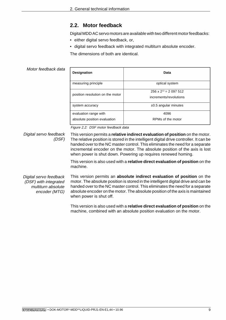
2.2. Motor feedbackDigital MDD AC servo motors are available with two different motor feedbacks:
• either digital servo feedback, or,
• digital servo feedback with integrated multiturn absolute encoder.
The dimensions of both are identical.
Motor feedback data
Figure 2.2: DSF motor feedback data
This version permits a relative indirect evaluation of position on the motor.The relative position is stored in the intelligent digital drive controller. It can behanded over to the NC master control. This eliminates the need for a separateincremental encoder on the motor. The absolute position of the axis is lostwhen power is shut down. Powering up requires renewed homing.
This version is also used with a relative direct evaluation of position on themachine.
This version permits an absolute indirect evaluation of position on themotor. The absolute position is stored in the intelligent digital drive and can behanded over to the NC master control. This eliminates the need for a separateabsolute encoder on the motor. The absolute position of the axis is maintainedwhen power is shut off.
This version is also used with a relative direct evaluation of position on themachine, combined with an absolute position evaluation on the motor.
Digital servo feedback(DSF)
Digital servo feedback(DSF) with integrated
multiturn absoluteencoder (MTG)
Designation Data
measuring principle optical system
position resolution on the motor256 x 213 = 2 097 512
increments/revolutions
system accuracy ±0.5 angular minutes
evaluation range with 4096
absolute position evaluation RPMs of the motor

10• DOK-MOTOR*-MDD**LIQUID-PRJ1-EN-E1,44 • 10.96
2. General technical information
2.3. Mechanical features
The output direction of the power connection can be selected in terms of theapplication, in other words, in accordance with the conditions at the machine.The following variations are available:
• connector towards side A
• connector towards side B
• connector to the right (view from the front onto the motor shaft, connectinghousing on top)
• connector to the left (view from the front onto the motor shaft, connectinghousing on top)
The following diameters are available to increase compatibility with the motorsof other manufacturers:
For the MDD 112 and 115
• ø 130 mm (standard)
• ø 180 mm
For the MDD 090 and 093
• ø 110 mm (standard)
• ø 130 mm
Plain output shaft (standard)
This achieves a torque transmission free of backlash with a non-positiveconnection. Clamping sets, pressure sleeves or similar clamping componentscan be used for coupling in pinions, belt pulleys or similar elements.
Output direction of thepower connection
Output shaft with keyway per DIN 6885, sheet 1 (edition dated 8/68)
This achieves a form-fitting torque transmission. This type of shaft-hubconnection is suitable for lesser demands. Multi-axial stress occurs at theshaft-hub connection due to torsion, bending, radial and axial loads. Duringpowerful reverse operations, the bottom of the key can turn out and reduce thequality of concentricity. Ever-increasing deformations can cause fractures.
Radial shaft load
The radial shaft load as relates to
• average speed
• and point of application of force
is depicted in section 3. Bearing lifespan was based on 30,000 working hours(calculations per ISO 281, edition dated 12/90).
Axial shaft load
The axial shaft load is outlined in section 3.
We recommend the use of plain shafts with friction-lockedconnections.
Centering diameters
Output shaft

11• DOK-MOTOR*-MDD**LIQUID-PRJ1-EN-E1,44 • 10.96
2. General technical information
Thermal deformations affect side A of the motor. This means that theA side of the motor shaft end can shift up to 0.6 mm with respect tothe motor housing. As a result there is a shifting of position
• of drive pinions with helical teeth mounted to the motor outputshaft but not axially fixed to the machine, or,
• of drive pinions with helical teeth axially fixed to the machine withbevel gear pinions on which thermal stress can occur. The lattercan lead to damage on side B of the motor.
The motors are available with holding brakes for a backlash-free holding offof the servo axis when no voltage is being applied. The holding brakesdeveloped for this motor series operate on the closed-circuit current principle.At zero current, a magnetic force acts on the brake armature disc. This meansthat the brake is locked and holding off the axis. With the application of 24VDC, the electrical field cancels the permanent magnetic field and the brakeopens.
The holding brake is available with different torques depending upon the typeof motor (see technical data).
The digital, intelligent drive controls the holding brake. This maintains the onand off sequence in all operating states. Current measurements in the drivemonitor the release of the holding brake. The moment of clamping of an E-stopor fault situation can be selected via parameters to suit the application:
• for example, either immediate clamping,
• clamping after speed falls below 10 min-1 , or,clamping after 400 ms -- even if speed exceeds 10 min-1.
Holding brake
The holding brake is not a working brake. It wears down afterapproximately 20,000 revolutions against the closed brake.
DDS intelligent digital drives with ANALOG interface achieve a drift-free standstill of the drive via a switching signal. The drive-internalspeed control holds the standstill position at zero without drift aslong as the drives are active.
Balance class It is possible to select the balance class for various motor applications inaccordance with DIN ISO 2373.
• class N (standard):
– for normal applications
• class R:
– for more demanding applications, e.g., grinding machines, or
– servo drives in main drive applications, e.g., drive tools on lathes.
These classes apply to an A side of a motor shaft without attachments.

12• DOK-MOTOR*-MDD**LIQUID-PRJ1-EN-E1,44 • 10.96
2.4. Electrical features
The terminal diagram depicted in Figure 2.3 is a schematic representation. Itis the checklist for all electrical connections required to operate a liquid-cooledMDD servo motor.
INDRAMAT MDD servomotors have standard electrical connections. Thisrestricts the variety of conductors. Sections 4 and 5 list the electrical connectionsfor all specific applications.
The following electrical connections are on the main spindle motor:
• power supply for temperature sensor and holding brake, and,
• motor feedback connection.
Figure 2.3: Schematic representation of main spindle motor terminal diagram
Motor power connectors are available for the electrical power connections for:
• crimping, or,
• soldering.
Motor power cables with metric cross sections can be either crimped orsoldered to the power connector. Those with inch cross sections can only besoldered.
Straight or elbow connectors are available to connect the motor feedback,depending upon installation requirements.
Terminal diagram(schematic)
Motor power connector
2. General technical information
drive
M
3
main spindlemotor
motorfeedback
holding brake
U mot
orte
mpe
ratu
rese
nsor
APMDD
Feedback connector

13• DOK-MOTOR*-MDD**LIQUID-PRJ1-EN-E1,44 • 10.96
side A side B
KDMDDWINKELST
2. General technical information
The elbow connectors are manufactured at the plant so that the cable outputdirection is the B side of the motor.
Elbow connector
Figure 2.4: Standard cable output direction if elbow connectors are used
The plug connector with screw cap can be turned in increments of 90° oncethe four fixing screws of the connector housing are released.
Do not damage the seal and cable strands when tightening thescrews.
Figure 2.5: Identifying the individual parts of the connectors
FABEZSTECK
mounting screws
connector housing
plug with screwed cap
14• DOK-MOTOR*-MDD**LIQUID-PRJ1-EN-E1,44 • 10.96
2. General technical information
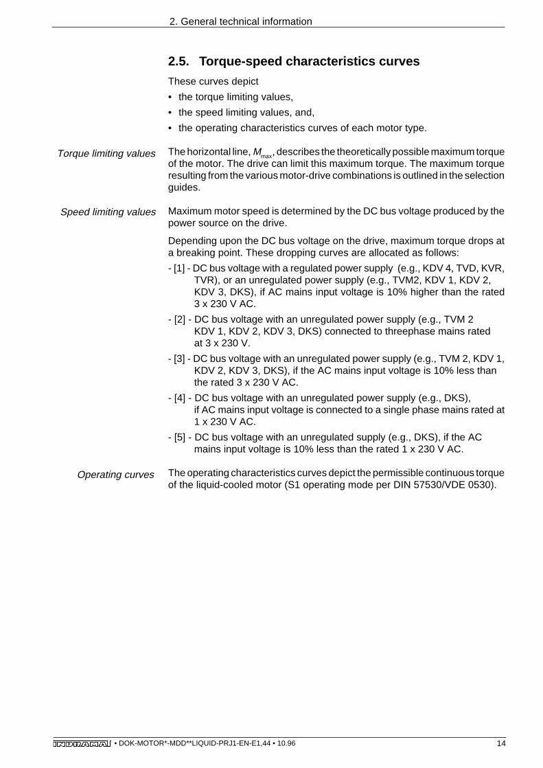
2.5. Torque-speed characteristics curves
These curves depict
• the torque limiting values,
• the speed limiting values, and,
• the operating characteristics curves of each motor type.
The horizontal line, Mmax, describes the theoretically possible maximum torqueof the motor. The drive can limit this maximum torque. The maximum torqueresulting from the various motor-drive combinations is outlined in the selectionguides.
Maximum motor speed is determined by the DC bus voltage produced by thepower source on the drive.
Depending upon the DC bus voltage on the drive, maximum torque drops ata breaking point. These dropping curves are allocated as follows:
- [1] - DC bus voltage with a regulated power supply (e.g., KDV 4, TVD, KVR,TVR), or an unregulated power supply (e.g., TVM2, KDV 1, KDV 2,KDV 3, DKS), if AC mains input voltage is 10% higher than the rated3 x 230 V AC.
- [2] - DC bus voltage with an unregulated power supply (e.g., TVM 2KDV 1, KDV 2, KDV 3, DKS) connected to threephase mains ratedat 3 x 230 V.
- [3] - DC bus voltage with an unregulated power supply (e.g., TVM 2, KDV 1,KDV 2, KDV 3, DKS), if the AC mains input voltage is 10% less thanthe rated 3 x 230 V AC.
- [4] - DC bus voltage with an unregulated power supply (e.g., DKS),if AC mains input voltage is connected to a single phase mains rated at1 x 230 V AC.
- [5] - DC bus voltage with an unregulated supply (e.g., DKS), if the ACmains input voltage is 10% less than the rated 1 x 230 V AC.
The operating characteristics curves depict the permissible continuous torqueof the liquid-cooled motor (S1 operating mode per DIN 57530/VDE 0530).
Torque limiting values
Speed limiting values
Operating curves

15• DOK-MOTOR*-MDD**LIQUID-PRJ1-EN-E1,44 • 10.96
2. General technical information
Application The speed-torque characteristics curves can be used:
• to record information from the selection documentation,
• to determine the possible maximum usable speed for a special applicationwith known torque requirements,
• and to check whether the application remains within the thermal limits of themotor. The root-mean-square torque for a critical cycle must be below theS1-continuous operating characteristic curve of the arithmetically averagedspeed.
Mmax
MdN
n
M
[5] [4] [3] [2] [1]
DGKENNLINIE
Figure 2.6: Schematic diagram of the torque-speed characteristics curves

16• DOK-MOTOR*-MDD**LIQUID-PRJ1-EN-E1,44 • 10.96
3. Technical data
3. Technical data
3.1. MDD 090 (liquid-cooled)
3.1.1. MDD 090 motor data
Fi T h i l d f MDD11 b i 1 00 d 2000 i 1
Motor type MDD . . . 090A-F-030
30006.9
11.717.832.2
0.00200.593.0813.420
12.5
090A-F-040
40006.9
17.715.141.3
0.00200.391.307.720
12.5
090A-F-020
20006.97.4
19.021.9
0.00200.936.8427.720
12.5
Basic motor speed 1)
Continuous stall torqueContinuous stall currentTheor. maximum speed 2)
Peak currentRotor inertia 3)
Torque constant at 20 oCWindings resistance at 20 oCWindings inductanceThermal time constantMass 3)
PvN
ϑambϑein
∆ϑN
QN∆pN
pmax
V
ϑL
420+5° to +45°+10° to +40°
10
0.60.33
-20° to +80°1000 meters above sea level
IP 65F
prime coat black (RAL 9005)
Rated power lossAmbient temperature 4)
Coolant entry temperatureCoolant temperature increase withPvNMinimum coolant flowthrough with∆ϑN
5)
Pressure drop with QN 5) 6)
Maximum system pressureVolume in coolant canalStorage and transportationtemperature 7)
Maximum installation altitudeProtection categoryInsulation classificationHousing finish
W°C°C
°C
l/minbarbar
l
°C
m
Symbol UnitDesignation
nMdNIdN
Mmax
ImaxJM
KmRA
LA
TthmM
min-1
NmA
NmA
kgm2
Nm/AOhmmHminkg
optionsholding brake, electrical release
Holding torqueRated voltageRated currentInertiaRelease delayClamping delayMass
6.524 ± 10%
0.651.06 x 10-4
60200.5
1124 ± 10%
0.651.06 x 10-4
60200.5
MH NmUN VIN AJB kgm2
tL mstK msmB kg
1) Usable motor speed is determined by the torque requirements of the application. The usable speeds nmaxfound in the selection lists of the motor-drive combinations are binding for standard applications. The usable speedsfor other applications can be found using the required torque in the torque-speed characteristics curves.
2) The maximum achievable torque depends upon the drive used.Only those maximum torques Mmax found in the selection list of the motor-drive combinations are binding.
3) Without holding brake.4) Note the relationship between the actual ϑamb and the ϑein: ϑein may be no more than 5 °C below ϑamb!5) With coolant water.6) Note flow diagram for deviating flow values.7) Empty of all coolant prior to transportation or storage.
Figure 3.1: MDD 090A (liquid-cooled) - technical data

17• DOK-MOTOR*-MDD**LIQUID-PRJ1-EN-E1,44 • 10.96
3. Technical data
Motor type MDD . . . 090B-F-030
300013.523.738.872.9
0.00360.570.914.73018
090B-F-040
400013.531.438.395.3
0.00360.430.502.63018
090B-F-020
200013.515.739.148.6
0.00360.861.9910.13018
nMdN
IdNMmax
Imax
JMKm
RALA
Tth
mM
PvN
ϑambϑein
∆ϑN
QN∆pN
pmax
V
ϑL
510+5° to +45°
+10° to +40°
10
0.70.33
3
-20° to +80°1000 meters above sea level
IP 65F
prime coat black (RAL 9005)
Basic motor speed 1)
Continuous stall torqueContinuous stall currentTheor. maximum speed 2)
Peak currentRotor inertia 3)
Torque constant at 20 oCWindings resistance at 20 oCWindings inductanceThermal time constantMass 3)
Rated power lossAmbient temperature 4)
Coolant entry temperatureCoolant temperature increase withPvN
Minimum coolant flow through with∆ϑN
5)
Pressure drop with QN 5) 6)
Maximum system pressureVolume in coolant canalStorage and transportationtemperature 7)
Maximum installation altitudeProtection categoryInsulation classificationHousing finish
Symbol UnitDesignation
min-1
NmA
NmA
kgm2
Nm/AOhmmHminkg
W°C°C
°C
l/minbarbar
l
°Cm
optionsholding brake, electrical release
Holding torqueRated voltageRated currentInertiaRelease delayClamping delayMass
MH NmUN VIN AJB kgm2
tL mstK msmB kg
6.524 ± 10%
0.651.06 x 10-4
60200.5
1124 ± 10%
0.651.06 x 10-4
60200.5
) Usable motor speed is determined by the torque requirements of the application. The usable speeds nmaxfound in the selection lists of the motor-drive combinations are binding for standard applications. The usable speedsfor other applications can be found using the required torque in the torque-speed characteristics curves.
2) The maximum achievable torque depends upon the drive used.Only those maximum torques Mmax found in the selection list of the motor-drive combinations are binding.
3) Without holding brake.4) Note the relationship between the actual ϑamb and the ϑein: ϑein may be no more than 5 °C below ϑamb!5) With coolant water.6) Note flow diagram for deviating flow values.7) Empty of all coolant prior to transportation or storage.
Figure 3.2: MDD 090B (liquid-cooled) - technical data

18• DOK-MOTOR*-MDD**LIQUID-PRJ1-EN-E1,44 • 10.96
3. Technical data
Motor type MDD . . . 090C-F-030
300019.536.858.3118
0.00530.530.462.63023
090C-F-040
400019.545.358.6146
0.00530.430.281.63023
090C-F-020
200019.522.758.672.9
0.00530.861.206.83023
Basic motor speed 1)
Continuous stall torqueContinuous stall currentTheor. maximum speed 2)
Peak currentRotor inertia 3)
Torque constant at 20 oCWindings resistance at 20 oCWindings inductanceThermal time constantMass 3)
nMdN
IdN
MmaxImax
JMKm
RA
LATth
mM
min-1
NmA
NmA
kgm2
Nm/AOhmmHminkg
PvN
ϑambϑein
∆ϑN
QN∆pN
pmax
V
ϑL
620+5° to +45°+10° to +40°
10
0.90.43
-20° to +80°1000 meters above sea level
IP 65F
prime coat black (RAL 9005)
Rated power lossAmbient temperature 4)
Coolant entry temperatureCoolant temperature increase withPvNMinimum coolant flow through with∆ϑN
5)
Pressure drop with QN 5) 6)
Maximum system pressureVolume in coolant canalStorage and transportationtemperature 7)
Maximum installation altitudeProtection categoryInsulation classificationHousing finish
Symbol UnitDesignation
W°C°C
°C
l/minbarbar
l
°Cm
optionsholding brake, electrical release
Holding torqueRated voltageRated currentInertiaRelease delayClamping delayMass
MH NmUN VIN AJB kgm2
tL mstK msmB kg
6,524 ± 10%
0.651.06 x 10-4
60200.5
1124 ± 10%
0.651.06 x 10-4
60200.5
1) Usable motor speed is determined by the torque requirements of the application. The usable speeds nmaxfound in the selection lists of the motor-drive combinations are binding for standard applications. The usable speedsfor other applications can be found using the required torque in the torque-speed characteristics curves.
2) The maximum achievable torque depends upon the drive used.Only those maximum torques Mmax found in the selection list of the motor-drive combinations are binding.
3) Without holding brake.4) Note the relationship between the actual ϑamb and the ϑein: ϑein may be no more than 5 °C below ϑamb!5) With coolant water.6) Note flow diagram for deviating flow values.7) Empty of all coolant prior to transportation or storage.
Figure 3.3: MDD 090C (liquid-cooled) - technical data

19• DOK-MOTOR*-MDD**LIQUID-PRJ1-EN-E1,44 • 10.96
3. Technical data
Figure 3.4: MDD 090A - characteristics curves
3.1.2. MDD 090 torque-speed characteristics curves
19.0
6.9
0
2
4
6
8
10
12
14
16
18
20
0 500 1000 1500 2000n/min-1
M/N
m
[5] [4] [3] [2] [1]
17.7
6.9
0
2
4
6
8
10
12
14
16
18
20
0 1000 2000n/min-1
M/N
m
3000
[4] [3] [1]
500 2500
15.0
6.9
0
2
4
6
8
10
12
14
16
18
20
0 1000 2000n/min-1
M/N
m
3000 4000 5000
[5] [2]
1500
[5] [4] [3] [2] [1]
DGMDD090A
MDD 090A-Fwith 2000 min-1
MDD 090A-Fwith 3000 min-1
MDD 090A-Fwith 4000 min-1

20• DOK-MOTOR*-MDD**LIQUID-PRJ1-EN-E1,44 • 10.96
3. Technical data
DGMDD090B
0
5
10
15
20
25
30
35
0 1000 2000n/min-1
M/N
m
3000500 25001500
40 39.0
[4] [3] [1][5] [2]
0
5
10
15
20
25
30
35
0 1000 2000n/min-1
M/N
m
3000500 25001500
40 38.9
13.5
40003500
[4] [3] [1][5] [2]
0
5
10
15
20
25
30
35
0 1000 2000n/min-1
M/N
m
3000
40 38.3
13.5
4000
[4] [3] [1][5] [2]
13.5
5000
Figure 3.5: MDD 090B - characteristics curves
MDD 090B-Fwith 2000 min-1
MDD 090B-Fwith 3000 min-1
MDD 090B-Fwith 4000 min-1

21• DOK-MOTOR*-MDD**LIQUID-PRJ1-EN-E1,44 • 10.96
3. Technical data
Figure 3.6: MDD 090C - characteristics curves
MDD 090C-Fwith 2000 min-1
MDD 090C-Fwith 3000 min-1
MDD 090C-Fwith 4000 min-1
DGMDD090C
19.5
0
10
20
30
50
0 1000 2000n/min-1
M/N
m
500 25001500
60
40 [4] [3] [1][5] [2]
58.6
19.5
0
10
20
30
50
0 1000 2000n/min-1
M/N
m
500 25001500
60
40 [4] [3][5] [2]
58.3
19.5
0
10
20
30
50
0 1000 2000n/min-1
M/N
m
40003000
60
40 [4] [1][5]
58.6
3000 40003500
5000
[3] [2]
[1]

22• DOK-MOTOR*-MDD**LIQUID-PRJ1-EN-E1,44 • 10.96
3. Technical data
3.1.3. MDD 090 - shaft load
Figure 3.8: Radial force
Faxial
= 0.34 • Fradial
Faxial - permissible axial force
Fradial - permissible radial force
Figure 3.7: Shaft load
20 40 x/mm600
800
1000
1200
1400
naverage
500 min-1
1000 min-1
2000 min-1
3000 min-1
4000 min-1
6000 min-1
Fra
dial
/N
5000 min-1
Fradial - permissible radial force as a function of distance, x, and average speed naverage
output shaft without keyway limit for output shaft with keyway per DIN 6885, sh. 1x - distance xnaverage- average servo motor speed (arithmetically determined)
Calculations based on:30,000 operating hours as nominalbearing lifespan L10h
For higher radial loads Fload bearing lifespan drops as follows:L10h = (Fradial /Fload)3 • 30 000 h DGMDD090RAD
1600
1800
10 30 50
Faxial
Fradial
x
FAMDD090WEL
Radial force Fradial
Axial force Faxial

23• DOK-MOTOR*-MDD**LIQUID-PRJ1-EN-E1,44 • 10.96
3. Technical data

24• DOK-MOTOR*-MDD**LIQUID-PRJ1-EN-E1,44 • 10.96
3. Technical data
3.1.4. MDD 090 - dimensional data
Figure 3.9: MDD 090 (liquid-cooled) - general dimensional data
Type S1 S2 S3 S4 S5 Pg
INS 108 130 45 110 110 49 21INS 172 2) 140 53 145 113 61 36
F Feedback connector:not supplied with motor
Name Connector Dim. F straight elbow INS 510
INS 511
INS 512 112 INS 513 110
A Table:
B position accuracy per tolerance R DIN 42 955
C
D
center drill hole DS M10 per DIN 332, sh. 2
E Motor power connector:Depends on motor, not suppliedwith motor.
Table:
Table:
108
D
∅11
0 j6
B
R 0.5
3
S3
A
1
ø28
k6
C
4
16
50
45°
45°
11S
1
25°
150
190
165
F
M10-22
F
X
4
E
E
S4
S2E
E
E
E
E
Pg
1) Larger with some options. The valid dimension is given with the option.
Size Dim.A 1)
MDD 090 A 275MDD 090 B 340MDD 090 C 405
Flange type determines mounting mode• as per design B5 (drill hole in flange)•as per design B14 (windings in flange)
2) for
130±0.2
4 x M8 - 12
General dimensions:
View X:
G 1/8"
67.5
S5E
A
76
∅98
27
F
2
62
MDD 090C-F-020,MDD 090C-F-030,MDD 090C-F-040
MBMDD090A
Z
Dim.

25• DOK-MOTOR*-MDD**LIQUID-PRJ1-EN-E1,44 • 10.96
3. Technical data
40
8t=7
40 4+0.1
8 N
9
1 Mounting direction of the motor power connector:• to side A• to side B• to the right looking towards the• to the left motor shaft
3
Output shaft:• plain shaft (preferred type)• with keyway per DIN 6885, sh.1 (Note: balanced with entire key!)
4
matching key: DIN 6885-A 8x7x404
2 Custom centering diameter: • Ø130 j6
Holding brake: • Holding torque: 6.5 Nm • Holding torque: 11 Nm
does not affect outer dimensions
Table for 6.5 and11 Nm holding torque
Option-dependent dimensions:
MBMDD090O
Side A is depicted as the outputdirection in the figure. The dimensionsfor other output directions are obtained by turning the connectorhousing around the Z axis.
Figure 3.10: MDD 090 (liquid-cooled) options-dependent data

26• DOK-MOTOR*-MDD**LIQUID-PRJ1-EN-E1,44 • 10.96
1. NameMotor for digital drives MDD
2. Motor size 090
3. Motor length A, B, C
4. Housing:for liquid-cooling F
5. Basic speed2000 min -1 0203000 min -1 0304000 min -1 040
6. Balance class N per DIN ISO 2373 N R per DIN ISO 2373 R
7. shaft end on side B standard (no second shaft end) 2
8. Motor feedback digital servo feedback L digital servo feedback with integrated multiturn encoder M
9. Centering diameterø110 mm 110ø130 mm 130
10. Output shaft plain shaft G shaft with keyway per DIN 6885, sheet 1 P
11. Output direction of the power connectionconnector towards side A Aconnector towards side B Bconnector to the right(view from front onto motor shaft, connector housing on top) Rconnector to the left(view from front onto motor shaft, connector housing on top) L
12. Holding brakeno holding brake 0with holding brake of 6.5 Nm 1with holding brake of 11.0 Nm 2
13. Custom versionsDetermined and documented by INDRAMAT with custom number.Type key field 13 does not apply to standard motors.
3.1.5. MDD 090 - type codes
3. Technical data
Type code fields Example: M D D 0 9 0 B - F - 0 2 0 - N 2 L - 1 1 0 G B 0 / S 0 0 0
Figure 3.11: MDD 090 (liquid-cooled) - available options

27• DOK-MOTOR*-MDD**LIQUID-PRJ1-EN-E1,44 • 10.96
3. Technical data
3.2. MDD 093 (liquid-cooled)
3.2.1. MDD 093 - motor data
Motor type MDD . . . 093A-F-030
300017.533.728.779.9
0.00220.520.614.92513
093A-F-040
400017.544.328.2
104.80.0022
0.390.382.82513
093A-F-020
200017.519.328.545.8
0.00220.901.8615.32513
Basic motor speed 1)
Continuous stall torqueContinuous stall currentTheor. maximum speed 2)
Peak currentRotor inertia 3)
Torque constant at 20 oCWindings resistance at 20 oCWindings inductanceThermal time constantMass 3)
nMdNIdN
MmaxImax
JM
KmRA
LATth
mM
PvN
ϑamb
ϑein
∆ϑN
QN
∆pNpmax
V
ϑL
W°C°C
°C
l/minbarbar
l
°Cm
730+5 to +45
+10 to +40
10
1.00.53
-20° to +80°1000 meters above sea level
IP 65F
prime coat black (RAL 9005)
Rated power lossAmbient temperature 4)
Coolant entry temperatureCoolant temperature increase withPvNMinimum coolant flow through with∆ϑN
5)
Pressure drop with QN 5) 6)
Maximum system pressureVolume in coolant canalStorage and transportationtemperature 7)
Maximum installation altitudeProtection categoryInsulation classificationHousing finish
093A-F-060
600017.570.028.6
165.80.0022
0.250.161.92513
Symbol UnitDesignation
min-1
NmA
NmA
kgm2
Nm/AOhmmHminkg
optionsholding brake, electrical release
Holding torqueRated voltageRated currentInertiaRelease delayClamping delayMass
MH NmUN VIN AJB kgm2
tL mstK msmB kg
1124 ± 10%
0,51.06 x 10-4
60200.5
2224 ± 10%
0.693.6 x 10-4
70301.1
1) Usable motor speed is determined by the torque requirements of the application. The usable speeds nmaxfound in the selection lists of the motor-drive combinations are binding for standard applications. The usable speedsfor other applications can be found using the required torque in the torque-speed characteristics curves.
2) The maximum achievable torque depends upon the drive used.Only those maximum torques Mmax found in the selection list of the motor-drive combinations are binding.
3) Without holding brake.4) Note the relationship between the actual ϑamb and the ϑein: ϑein may be no more than 5 °C below ϑamb!5) With coolant water.6) Note flow diagram for deviating flow values.7) Empty of all coolant prior to transportation or storage.
Figure 3.12: Technical data for MDD 093A (liquid-cooled)

28• DOK-MOTOR*-MDD**LIQUID-PRJ1-EN-E1,44 • 10.96
Motor type MDD . . . 093B-F-030
300027.645.744.9108
0.00290.600.434.425
16.5
093B-F-040
400027.669.645.5165
0.00290.400.201.925
16.5
093B-F-020
200027.632.145.276.0
0.00290.860.771125
16.5
Basic motor speed 1)
Continuous stall torqueContinuous stall currentTheor. maximum speed 2)
Peak currentRotor inertia 3)
Torque constant at 20 oCWindings resistance at 20 oCWindings inductanceThermal time constantMass 3)
nMdN
IdN
MmaxImax
JMKm
RA
LATth
mM
min-1
NmA
NmA
kgm2
Nm/AOhmmHminkg
PvN
ϑambϑein
∆ϑN
QN∆pN
pmax
V
ϑL
W°C°C
°C
l/minbarbar
l
°Cm
870+5° to +45°
+10° to +40°
10
1.30.73
-20° to +80°1000 meters above sea level
IP 65F
prime coat black (RAL 9005)
093B-F-060
600027,688,845,0210
0.00290.310.111.125
16.5
3. Technical data
Symbol UnitDesignation
optionsholding brake, electrical release
Holding torqueRated voltageRated currentInertiaRelease delayClamping delayMass
MH NmUN VIN AJB kgm2
tL mstK msmB kg
1124 ± 10%
0.51.06 x 10-4
60200.5
2224 ± 10%
0.693.6 x 10-4
70301.1
1) Usable motor speed is determined by the torque requirements of the application. The usable speeds nmaxfound in the selection lists of the motor-drive combinations are binding for standard applications. The usable speedsfor other applications can be found using the required torque in the torque-speed characteristics curves.
2) The maximum achievable torque depends upon the drive used.Only those maximum torques Mmax found in the selection list of the motor-drive combinations are binding.
3) Without holding brake.4) Note the relationship between the actual ϑamb and the ϑein: ϑein may be no more than 5 °C below ϑamb!5) With coolant water.6) Note flow diagram for deviating flow values.7) Empty of all coolant prior to transportation or storage.
Figure 3.13: Technical data for MDD 093B (liquid-cooled)
Rated power lossAmbient temperature 4)
Coolant entry temperatureCoolant temperature increase withPvNMinimum coolant flow through with∆ϑN
5)
Pressure drop with QN 5) 6)
Maximum system pressureVolume in coolant canalStorage and transportationtemperature 7)
Maximum installation altitudeProtection categoryInsulation classificationHousing finish

29• DOK-MOTOR*-MDD**LIQUID-PRJ1-EN-E1,44 • 10.96
Motor type MDD . . .
Symbol UnitDesignation
093C-F-030
300037.161.261.1145
0.00420.610.252.72522
093C-F-040
400037.186.160.6204
0.00420.430.141.62522
093C-F-020
200037.140.760.696.5
0.00420.910.566.12522
Basic motor speed 1)
Continuous stall torqueContinuous stall currentTheor. maximum speed 2)
Peak currentRotor inertia 3)
Torque constant at 20 oCWindings resistance at 20 oCWindings inductanceThermal time constantMass 3)
nMdN
IdN
MmaxImax
JMKm
RA
LATth
mM
970+5° to +45°
+10° to +40°
10
1.40.73
-20° to +80°1000 meters above sea level
IP 65F
prime coat black (RAL 9005)
093C-F-060
600030.9
102.960.8293
0.00420.300.070.72522
3. Technical data
PvN
ϑambϑein
∆ϑN
QN∆pN
pmax
V
ϑL
W°C°C
°C
l/minbarbar
l
°Cm
Rated power lossAmbient temperature 4)
Coolant entry temperatureCoolant temperature increase withPvNMinimum coolant flow through with∆ϑN
5)
Pressure drop with QN 5) 6)
Maximum system pressureVolume in coolant canalStorage and transportationtemperature 7)
Maximum installation altitudeProtection categoryInsulation classificationHousing finish
min-1
NmA
NmA
kgm2
Nm/AOhmmHminkg
optionsholding brake, electrical release
Holding torqueRated voltageRated currentInertiaRelease delayClamping delayMass
1124 ± 10%
0.51.06 x 10-4
60200.5
2224 ± 10%
0.693.6 x 10-4
70301.1
MH NmUN VIN AJB kgm2
tL mstK msmB kg
1) Usable motor speed is determined by the torque requirements of the application. The usable speeds nmaxfound in the selection lists of the motor-drive combinations are binding for standard applications. The usable speedsfor other applications can be found using the required torque in the torque-speed characteristics curves.
2) The maximum achievable torque depends upon the drive used.Only those maximum torques Mmax found in the selection list of the motor-drive combinations are binding.
3) Without holding brake.4) Note the relationship between the actual ϑamb and the ϑein: ϑein may be no more than 5 °C below ϑamb!5) With coolant water.6) Note flow diagram for deviating flow values.7) Empty of all coolant prior to transportation or storage.
Figure 3.14: Technical data for MDD 093C (liquid-cooled)

30• DOK-MOTOR*-MDD**LIQUID-PRJ1-EN-E1,44 • 10.96
Figure 3.15: Technical data for MDD 093D (liquid-cooled)
3. Technical data
in preparation

31• DOK-MOTOR*-MDD**LIQUID-PRJ1-EN-E1,44 • 10.96
3.2.2. MDD 093 - torque-speed characteristics curves
3. Technical data
DGMDD093A
0
5
10
15
25
0 1000 2000n/min-1
M/N
m
500 1500
30
20[4] [3] [1][5] [2]
28.6
17.5
0
5
10
15
25
0 1000 2000n/min-1
M/N
m
500 1500
30
20
28.6
17.5
0
5
10
15
25
0 1000 2000n/min-1
M/N
m
500 1500
30
20
28.6
[4] [3] [1][5] [2]
30002500 3500
[4] [3] [1][5] [2]17.5
2500 3000 40003500 4500
Figure 3.16: Torque-speed characteristics curves for MDD 093A
MDD 093A-Fwith 4000 min-1
MDD 093A-Fwith 3000 min-1
MDD 093A-Fwith 2000 min-1

32• DOK-MOTOR*-MDD**LIQUID-PRJ1-EN-E1,44 • 10.96
3. Technical data
Figure 3.17: Torque-speed characteristics curves for MDD 093A and MDD 093B
MDD 093B-Fwith 3000 min-1
MDD 093B-Fwith 2000 min-1
MDD 093A-Fwith 6000 min-1
n/min-1
n/min-1
M/N
m
DGMDD093AB
0
5
10
15
25
0 1000 2000n/min-1
M/N
m
3000
30
20
28.6
17.5
05
10
15
25
0 1000 2000500 1500
30
20
45.1
2500
4000 5000 6000
[4] [3] [1][5] [2]
35
45
40[4] [3] [1][5] [2]
27.6
05
10
15
25
0 1000 2000500 1500
30
20
45.1
2500
35
45
40
27.6
[4] [3] [1][5] [2]
3000 3500
M/N
m
33• DOK-MOTOR*-MDD**LIQUID-PRJ1-EN-E1,44 • 10.96
3. Technical data
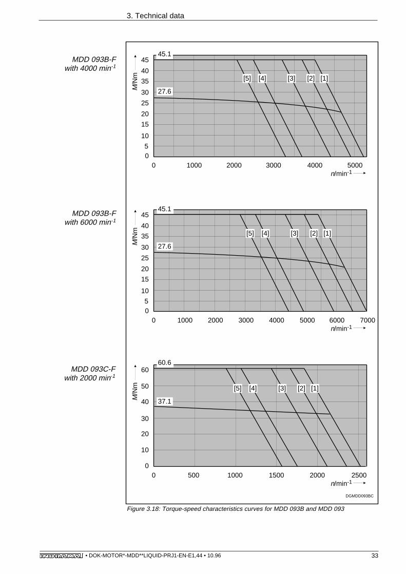
Figure 3.18: Torque-speed characteristics curves for MDD 093B and MDD 093
MDD 093C-Fwith 2000 min-1
MDD 093B-Fwith 6000 min-1
MDD 093B-Fwith 4000 min-1
DGMDD093BC
05
10
15
25
0 1000 2000n/min-1
M/N
m
3000
30
20
45.1
4000
35
45
40
27.6
05
10
15
25
0 2000 40001000 3000
30
20
45.1
5000
35
45
40
27.6
6000 7000
[4] [3] [1][5] [2]
5000
[4] [3] [1][5] [2]
0
10
0 20001000
30
20
60.6
50
60
40
[4] [3] [1][5] [2]
37.1
n/min-1
M/N
m
n/min-1
M/N
m
1500500 2500

34• DOK-MOTOR*-MDD**LIQUID-PRJ1-EN-E1,44 • 10.96
3. Technical data
Figure 3.19: Torque-speed characteristics curves for MDD 093C
MDD 093C-Fwith 6000 min-1
MDD 093C-Fwith 4000 min-1
MDD 093C-Fwith 3000 min-1
DGMDD093C
0
10
0 2000 40001000 3000
30
20
60.6
5000
50
60
40
6000 7000
0
10
0 2000 40001000 3000
30
20
60.6
3500
50
60
40
500 1500
37.1
0
10
0 20001500n/min-1
M/N
m
1000 3000
30
20
60.6
2500
50
60
40
3500500
37.1
[4] [3] [1][5] [2]
[4] [3] [1][5] [2]
2500 4500
[4] [3] [1][5] [2]
30.9
n/min-1
M/N
m
n/min-1
M/N
m

35• DOK-MOTOR*-MDD**LIQUID-PRJ1-EN-E1,44 • 10.96
3. Technical data
in preparation
Figure 3.20: Torque-speed characteristics curves for MDD 093D
MDD 093D-Fwith 3000 min-1
MDD 093D-Fwith 2000 min-1
MDD 093D-Fwith 1500 min-1

36• DOK-MOTOR*-MDD**LIQUID-PRJ1-EN-E1,44 • 10.96
3. Technical data
MDD 093D-Fwith 4000 min-1
in preparation
Figure 3.21: Torque-speed characteristics curves for MDD 093D

37• DOK-MOTOR*-MDD**LIQUID-PRJ1-EN-E1,44 • 10.96
Figure 3.23: Radial force
Faxial
= 0.34 • Fradial
Faxial - permissible axial force
Fradial - permissible radial force
Axial force Faxial
Radial force Fradial
Figure 3.22: Shaft load
3. Technical data
3.2.3. MDD 093 - shaft load
Faxial
Fradial
x
FAMDD093WEL
20 40 x/mm600
800
1000
1200
1400
naverage
500 min-1
1000 min-1
2000 min-1
3000 min-1
4000 min-1
6000 min-1
Fra
dial
/N
5000 min-1
Fradial - radial force as a function of distance, x, and average speed, naverage
output shaft without keyway limit with output shaft with keyway as per DIN 6885, sh.1x - distance xnaverage - average servo motor speed (arithmetically determined)
Calculations based on:30 000 operating hours as nominalbearing lifespan L10h
For higher radial loads, Fload, bearinglifespan is reduced as follows:L10h = (Fradial /Fload)3 • 30,000 hrs. DGMDD093RAD
1600
1800
10 30 50

38• DOK-MOTOR*-MDD**LIQUID-PRJ1-EN-E1,44 • 10.96
3.2.4. MDD 093 - dimensional data
Figure 3.24: General data on MDD 093 (liquid-cooled)
3. Technical data
Typ S1 S2 S3 S4 S5 Pg
INS 108 2) 130 45 110 110 49 21INS 172 137 52 145 112 55,5 36
Size Dim. A 1)
MDD 093 A 286MDD 093 B 327MDD 093 C 386MDD 093 D 436
F Feedback connector:Not delivered with motor.
Name Connector Dim. F straight elbow INS 510
INS 511
INS 512 112 INS 513 110
A Table:
B Position accuracy as per tolerance R DIN 42 955
C
D
center drill hole DS M10 per DIN 332, sh. 2
E Motor power connector:Depends on motor, not delivered with motor.
Table:
Table:
108
D
∅11
0 j6
B
R0.5
3
S3
A
1
ø28
k6
C
4
16
50
45°
45°
11S
1
25°
150
190
165
F
M10-22
F
X
4
E
E
S4
S2E
E
E
E
E
Pg
1) Larger with some options. The applicable dimensions are given with the option.
Flange type determines mounting mode• as per design B5 (drill hole in flange)• as per design B14 (windings in flange)
2) for MDD 093 A - F - 020, MDD 093 B - F - 020,
MDD 093 A - F - 030,
130±0.2
4 x M8 - 12
General dimensions:
S5E
A
76
∅98
27
F
2
View X:
G 1/8"
67.5
62
MBMDD093A
Z
Maß

39• DOK-MOTOR*-MDD**LIQUID-PRJ1-EN-E1,44 • 10.96
3. Technical data
MBMDD093O
40
8t=7
40 4+0.1
8 N
9
1 Mounting direction of motor power connector:• to side A• to side B• to the right looking towards motor• to the left shaft
3
Output shaft:• plain shaft (preferred type)• with keyway as per DIN 6885, sh. 1 (Note: balanced with entire key!)
4
matching key: DIN 6885-A 8x7x404
2 Custom centering diameter: • Ø130 j6
Size Dim. A MDD 093 A 316MDD 093 B 357MDD 093 C 416MDD 093 D 466
Holding brake: • Holding torque of 11 Nm • Holding torque of 22 Nm
does not affect outer dimensions
Table for holding torque
of 11 Nm
Table for holding torqueof 22 Nm
Options-dependent dimensions:
Side A is depicted as the outputdirection in the drawing. Thedimensions of other outputdirections can be obtained byturning the housing around theZ axis.
Figure 3.25: Options-dependent dimensions for MDD 093 (liquid-cooled)

40• DOK-MOTOR*-MDD**LIQUID-PRJ1-EN-E1,44 • 10.96
3.2.5. MDD 093 - type codes
3. Technical data
1. DesignationMotor for digital drives MDD
2. Motor size 093
3. Motor length A, B, C, D
4. Housing:for liquid-cooling F
5. Rated speed 1500 min -1 015 1)
2000 min -1 0203000 min -1 0304000 min -1 0406000 min -1 060 2)
6. Balance class N per DIN ISO 2373 N R per DIN ISO 2373 R
7. Shaft end on side B Standard (without second shaft end) 2
8. Motor feedback digital servo feedback L digital servo feedback with integrated multiturn encoder M
9. Centering diameterø110 mm 110ø130 mm 130
10. Output shaft plain shaft G shaft with keyway per DIN 6885, sheet 1 P
11. Output direction of power connectionTo side ATo side BTo the right(looking towards shaft, housing on top) RTo the left(looking towards shaft, housing on top) L
12. Holding brakeno holding brake 0with holding brake of 11.0 Nm 1with holding brake of 22.0 Nm 2
13. Custom versionFixed and documented by INDRAMAT with custom number.Field 13 does not apply to standard motors
Type codes: Example: M D D 0 9 3 B - F - 0 2 0 - N 2 L - 1 1 0 G B 0 / S 0 0 0
1) only for motor length "D"2) not for motor length "D"
Figure 3.26: Options for MDD 093 (liquid-cooled)

41• DOK-MOTOR*-MDD**LIQUID-PRJ1-EN-E1,44 • 10.96
3. Technical data
3.3. MDD 112 (liquid-cooled)
3.3.1. MDD 112 - motor data
Motor type MDD . . . 112A-F-020
200019.622.030.837.0
0.00610.891.40175025
112A-F-030
300019.632.131.555.3
0.00610.610.666.85025
112A-F-015
150019.615.631.426.7
0.00611.262.94335025
720+5° to +45°
+10° to +40°
10
1.00.53
-20° to +80°1000 meters above sea level
IP 65F
prime coat black (RAL 9005)
112A-F-040
400019.642.631.372.9
0.00610.460.384.05025
Basic motor speed 1)
Continuous stall torqueContinuous stall currentTheor. maximum speed 2)
Peak currentRotor inertia 3)
Torque constant at 20 oCWindings resistance at 20 oCWindings inductanceThermal time constantMass 3)
nMdNIdN
MmaxImax
JM
KmRA
LATth
mM
PvN
ϑamb
ϑein
∆ϑN
QN
∆pNpmax
V
ϑL
W°C°C
°C
l/minbarbar
l
°Cm
Rated power lossAmbient temperature 4)
Coolant entry temperatureCoolant temperature increase withPvNMinimum coolant flow through with∆ϑN
5)
Pressure drop with QN 5) 6)
Maximum system pressureVolume in coolant canalStorage and transportationtemperature 7)
Maximum installation altitudeProtection categoryInsulation classificationHousing finish
min-1
NmA
NmA
kgm2
Nm/AOhmmHminkg
optionsholding brake, electrical release
Holding torqueRated voltageRated currentInertiaRelease delayClamping delayMass
MH NmUN VIN AJB kgm2
tL mstK msmB kg
1) Usable motor speed is determined by the torque requirements of the application. The usable speeds nmaxfound in the selection lists of the motor-drive combinations are binding for standard applications. The usable speedsfor other applications can be found using the required torque in the torque-speed characteristics curves.
2) The maximum achievable torque depends upon the drive used.Only those maximum torques Mmax found in the selection list of the motor-drive combinations are binding.
3) Without holding brake.4) Note the relationship between the actual ϑamb and the ϑein: ϑein may be no more than 5 °C below ϑamb!5) With coolant water.6) Note flow diagram for deviating flow values.7) Empty of all coolant prior to transportation or storage.
Figure 3.27: Technical data for MDD 112A (liquid-cooled)
Symbol UnitDesignation
1424 ± 10%
0.753.6 x 10-4
70301.1

42• DOK-MOTOR*-MDD**LIQUID-PRJ1-EN-E1,44 • 10.96
Motor type MDD . . . 112B-F-020
200032.738.964.882.6
0.0120.840.435.75036
112B-F-030
300032.752.764.0111
0.0120.620.253.15036
112B-F-015
150032.727.761.055.3
0.0121.180.85155036
680+5° to +45°+10° to +40°
10
1.00.53
-20° to +80°1000 meters above sea level
IP 65F
prime coat black (RAL 9005)
112B-F-040
400032.777.465.3166
0.0120.420.112.05036
3. Technical data
Basic motor speed 1)
Continuous stall torqueContinuous stall currentTheor. maximum speed 2)
Peak currentRotor inertia 3)
Torque constant at 20 oCWindings resistance at 20 oCWindings inductanceThermal time constantMass 3)
nMdN
IdN
MmaxImax
JMKm
RA
LATth
mM
min-1
NmA
NmA
kgm2
Nm/AOhmmHminkg
PvN
ϑambϑein
∆ϑN
QN∆pN
pmax
V
ϑL
W°C°C
°C
l/minbarbar
l
°Cm
optionsholding brake, electrical release
Holding torqueRated voltageRated currentInertiaRelease delayClamping delayMass
MH NmUN VIN AJB kgm2
tL mstK msmB kg
1) Usable motor speed is determined by the torque requirements of the application. The usable speeds nmaxfound in the selection lists of the motor-drive combinations are binding for standard applications. The usable speedsfor other applications can be found using the required torque in the torque-speed characteristics curves.
2) The maximum achievable torque depends upon the drive used.Only those maximum torques Mmax found in the selection list of the motor-drive combinations are binding.
3) Without holding brake.4) Note the relationship between the actual ϑamb and the ϑein: ϑein may be no more than 5 °C below ϑamb!5) With coolant water.6) Note flow diagram for deviating flow values.7) Empty of all coolant prior to transportation or storage.
Rated power lossAmbient temperature 4)
Coolant entry temperatureCoolant temperature increase withPvNMinimum coolant flow through with∆ϑN
5)
Pressure drop with QN 5) 6)
Maximum system pressureVolume in coolant canalStorage and transportationtemperature 7)
Maximum installation altitudeProtection categoryInsulation classificationHousing finish
Figure 3.28: Technical data for MDD 112B (liquid-cooled)
Symbol UnitDesignation
1424 ± 10%
0.753.6 x 10-4
70301.1
4024 ± 10%
1.3532 x 10⁻⁴
150303.5
6024 ± 10%
1.3532 x 10⁻⁴
150303.5

43• DOK-MOTOR*-MDD**LIQUID-PRJ1-EN-E1,44 • 10.96
Motor type MDD . . . 112C-F-020
200052.355.697.1111
0.0170.940.315,05048
112C-F-030
300052.380.5101166
0.0170.650.142.05048
112C-F-015
150052.341.597.382.6
0.0171.260.567.95048
980+5° to +45°+10° to +40°
10
1.40.73
-20° to +80°1000 meters above sea level
IP 65F
prime coat black (RAL 9005)
112C-F-040
400049.4
102.999.7222
0.0170.480.081.55048
3. Technical data
Rated power lossAmbient temperature 4)
Coolant entry temperatureCoolant temperature increase withPvNMinimum coolant flow through with∆ϑN
5)
Pressure drop with QN 5) 6)
Maximum system pressureVolume in coolant canalStorage and transportationtemperature 7)
Maximum installation altitudeProtection categoryInsulation classificationHousing finish
optionsholding brake, electrical release
Holding torqueRated voltageRated currentInertiaRelease delayClamping delayMass
MH NmUN VIN AJB kgm2
tL mstK msmB kg
1) Usable motor speed is determined by the torque requirements of the application. The usable speeds nmaxfound in the selection lists of the motor-drive combinations are binding for standard applications. The usable speedsfor other applications can be found using the required torque in the torque-speed characteristics curves.
2) The maximum achievable torque depends upon the drive used.Only those maximum torques Mmax found in the selection list of the motor-drive combinations are binding.
3) Without holding brake.4) Note the relationship between the actual ϑamb and the ϑein: ϑein may be no more than 5 °C below ϑamb!5) With coolant water.6) Note flow diagram for deviating flow values.7) Empty of all coolant prior to transportation or storage.
Basic motor speed 1)
Continuous stall torqueContinuous stall currentTheor. maximum speed 2)
Peak currentRotor inertia 3)
Torque constant at 20 oCWindings resistance at 20 oCWindings inductanceThermal time constantMass 3)
nMdN
IdNMmax
Imax
JMKm
RALA
Tth
mM
min-1
NmA
NmA
kgm2
Nm/AOhmmHminkg
Figure 3.29: Technical data for MDD 112C (liquid-cooled)
Symbol UnitDesignation
W°C°C
°C
l/minbarbar
l
°Cm
PvN
ϑambϑein
∆ϑN
QN∆pN
pmax
V
ϑL
1424 ± 10%
0.753.6 x 10-4
70301.1
4024 ± 10%
1.3532 x 10⁻⁴
150303.5
6024 ± 10%
1.3532 x 10⁻⁴
150303.5

44• DOK-MOTOR*-MDD**LIQUID-PRJ1-EN-E1,44 • 10.96
Motor type MDD . . . 112D-F-020
200071.081.6135166
0.0230.870.182.76059
112D-F-030
300064.8
102.9131222
0.0230.630.101.56059
112D-F-015
150071.055.5132111
0.0231.280.395,96059
1240+5° to +45°+10° to +40°
10
1.81.03
-20° to +80°1000 meters above sea level
IP 65F
prime coat black (RAL 9005)
112D-F-040
400044.2
102.9132329
0.0230.430.051.06059
3. Technical data
PvN
ϑambϑein
∆ϑN
QN∆pN
pmax
V
ϑL
W°C°C
°C
l/minbarbar
l
°Cm
optionsholding brake, electrical release
Holding torqueRated voltageRated currentInertiaRelease delayClamping delayMass
MH NmUN VIN AJB kgm2
tL mstK msmB kg
) Usable motor speed is determined by the torque requirements of the application. The usable speeds nmaxfound in the selection lists of the motor-drive combinations are binding for standard applications. The usable speedsfor other applications can be found using the required torque in the torque-speed characteristics curves.
2) The maximum achievable torque depends upon the drive used.Only those maximum torques Mmax found in the selection list of the motor-drive combinations are binding.
3) Without holding brake.4) Note the relationship between the actual ϑamb and the ϑein: ϑein may be no more than 5 °C below ϑamb!5) With coolant water.6) Note flow diagram for deviating flow values.7) Empty of all coolant prior to transportation or storage.
Rated power lossAmbient temperature 4)
Coolant entry temperatureCoolant temperature increase withPvNMinimum coolant flow through with∆ϑN
5)
Pressure drop with QN 5) 6)
Maximum system pressureVolume in coolant canalStorage and transportationtemperature 7)
Maximum installation altitudeProtection categoryInsulation classificationHousing finish
Basic motor speed 1)
Continuous stall torqueContinuous stall currentTheor. maximum speed 2)
Peak currentRotor inertia 3)
Torque constant at 20 oCWindings resistance at 20 oCWindings inductanceThermal time constantMass 3)
nMdN
IdNMmax
ImaxJM
Km
RALA
TthmM
min-1
NmA
NmA
kgm2
Nm/AOhmmHminkg
Symbol UnitDesignation
Figure 3.30: Technical data for MDD 112D (liquid-cooled)
1424 ± 10%
0.753.6 x 10-4
70301.1
4024 ± 10%
1.3532 x 10⁻⁴
150303.5
6024 ± 10%
1.3532 x 10⁻⁴
150303.5

45• DOK-MOTOR*-MDD**LIQUID-PRJ1-EN-E1,44 • 10.96
3.3.2. Torque-speed characteristics curves for MDD 112
3. Technical data
Figure 3.31: Torque-speed characteristics curves for MDD 112A
MDD 112A-Fwith 3000 min-1
MDD 112A-Fwith 2000 min-1
MDD 112A-Fwith 1500 min-1
DGMDD112A
0
10
0 1500n/min-1
M/N
m
1000
30
20
31.4
5
500
19.6
15
35
25[4] [3] [1][5] [2]
0
10
0 15001000
30
20
30.7
5
500
19.6
15
35
25
0
10
0 15001000
30
20
31.3
5
500
19.6
15
35
25
2000
25002000 3000
[4] [3] [1][5] [2]
[4] [3] [1][5] [2]
n/min-1
M/N
m
n/min-1
M/N
m

46• DOK-MOTOR*-MDD**LIQUID-PRJ1-EN-E1,44 • 10.96
3. Technical data
Figure 3.32: Torque-speed characteristics curves for MDD 112A und MDD 112B
MDD 112B-Fwith 2000 min-1
MDD 112B-Fwith 1500 min-1
MDD 112A-Fwith 4000 min-1
DGMDD112AB
0
10
0 1500n/min-1
M/N
m
1000
30
20
31.1
5
500
19.6
15
35
25[4] [3] [1][5] [2]
0
10
0 15001000
30
20
64.5
500
32.740
70
50
25002000 35003000 45004000
60[4] [3] [1][5] [2]
0
10
0 15001000
30
20
65.1
500
32.740
70
50
60
25002000
[4] [3] [1][5] [2]
n/min-1
M/N
m
n/min-1
M/N
m

47• DOK-MOTOR*-MDD**LIQUID-PRJ1-EN-E1,44 • 10.96
3. Technical data
Figure 3.33: Torque-speed characteristics curves for MDD 112B und MDD 112C
MDD 112C-Fwith 1500 min-1
MDD 112B-Fwith 4000 min-1
MDD 112B-Fwith 3000 min-1
DGMDD112BC
0
10
0 1500n/min-1
M/N
m
1000
30
20
64.5
500
32.740
70
50
60[4] [3] [1][5]
0
10
0 15001000
30
20
65.5
500
32.740
70
50
60
25002000
25002000 35003000
[2]
[4] [3] [1][5] [2]
35003000 45004000
00 500
20
40
100
80
60
1000 1500 2000
97.2
[4] [3] [1][5] [2]
52.3
n/min-1
M/N
m
n/min-1
M/N
m

48• DOK-MOTOR*-MDD**LIQUID-PRJ1-EN-E1,44 • 10.96
3. Technical data
Figure 3.34: Torque-speed characteristics curves for MDD 112C
MDD 112C-Fwith 4000 min-1
MDD 112C-Fwith 3000 min-1
MDD 112C-Fwith 2000 min-1
DGMDD112C
00 1000
20
40
100
80
60
2000 3000 4000
100.1
49.4
00 1000
20
40
100
80
60
2000 3000500
100.4
52.3
00
n/min-1
M/N
m
1000
20
40
100
80
60
2000500 1500
97.3
52.3
[4] [3] [1][5] [2]
1500 2500 3500
[4] [3] [1][5] [2]
[4] [3] [1][5] [2]
1500 2500 3500 4500500
n/min-1
M/N
m
n/min-1
M/N
m

49• DOK-MOTOR*-MDD**LIQUID-PRJ1-EN-E1,44 • 10.96
3. Technical data
Figure 3.35: Torque-speed characteristics curves for MDD 112D
MDD 112D-Fwith 3000 min-1
MDD 112D-Fwith 2000 min-1
MDD 112D-Fwith 1500 min-1
DGMDD112D
00
n/min-1
M/N
m
1000
20
40
100
80
60
500 1500
132.4
120
140
[4] [3] [1][5] [2]
71.0
00 1000
20
40
100
80
60
500 1500
134.8
120
140
71.0
2000 2500
[4] [3] [1][5] [2]
00 1000
20
40
100
80
60
500 1500
130.2
120
140
64.8
2000 2500
[4] [3] [1][5] [2]
3000 3500
n/min-1
M/N
m
n/min-1
M/N
m

50• DOK-MOTOR*-MDD**LIQUID-PRJ1-EN-E1,44 • 10.96
3. Technical data
MDD 112D-Fwith 4000 min-1
DGMDD112D
00
n/min-1
M/N
m
1000
20
40
100
80
60
500 1500
132.2
120
140
44.2
2000 2500 3000 3500 4000 4500
[4] [3] [1][5] [2]
Figure 3.36: Torque-speed characteristics curves for MDD 112D

51• DOK-MOTOR*-MDD**LIQUID-PRJ1-EN-E1,44 • 10.96
3.3.3 MDD 112 - shaft load
Figure 3.38: Radial force
Faxial
= 0.35 • Fradial
Faxial - permissible axial force
Fradial - permissible radial force
Axial force Faxial
Radial force Fradial
Figure 3.37: Shaft load
3. Technical data
Faxial
Fradial
x
FAMDD112WEL
20 40 x/mm1000
1500
2000
2500
3000
naverage
500 min-1
1000 min-1
2000 min-1
3000 min-1
4000 min-1
6000 min-1
Fra
dial
/N
5000 min-1
60
Fradial - radial force as a function of distance, x, and average speed, naverage output shaft without keyway
limit with output shaft with keyway as per DIN 6885, sh.1
x - distance x
naverage - average servo motor speed (arithmetically determined)
Calculations based on:30 000 operating hours as nominalbearing lifespan L10h
For higher radial loads, Fload, bearinglifespan is reduced as follows:
L10h = (Fradial /Fload)3 • 30,000 hrs.
DGMDD112RAD
3500
4000
10 30 50

52• DOK-MOTOR*-MDD**LIQUID-PRJ1-EN-E1,44 • 10.96
3.3.4. MDD 112 - dimensional data
3. Technical data
Figure 3.39: General data on MDD 112 (liquid-cooled)
S3
1E
Pg
E
E
F Feedback connector:Not delivered with motor
Name Connector Dim. F straight elbow
INS 510 INS 511
INS 512 112 INS 513 110
A Table:
B position accuracy per tolerance R DIN 42 955
C
D
center drill hole DS M12 per DIN 332 sh. 2
E Motor power connector:Depends on motor, not delivered with motor.
Table:
Table:
108
D
∅13
0 j6
B
R1
76
∅98
3
27S5
A
F
ø38
k6
C
4
18
60
45°
45°
14S
1
25°
193
245
215
F
M12-28
F
X
4
E
S4
S2
E
E
E
1) Larger with some options. The applicable dimension is given with the option.
flange determines mounting mode• per design B5 (drill hole in flange)• per design B14 (windings in flange)
165±0.2
4 x M10 - 15
Type S1 S2 S3 S4 S5 1) Pg
INS 108 2) 151 45 110 133 56 21INS 172 160 52 145 137 62,5 36Size Dim.A 1)
MDD 112 A 312 MDD 112 B 387 MDD 112 C 462 MDD 112 D 537
2
General dimensions:
View X:
G 1/8"
88
92
E
2) for MDD 112 A - F - 015MDD 112 B - F - 015MDD 112 A - F - 020MDD 112 A - F - 030
A
MBMDD112A
Z
Dim.

53• DOK-MOTOR*-MDD**LIQUID-PRJ1-EN-E1,44 • 10.96
3. Technical data
MBMDD112O45
10t=8
455+0.2
10 N
9
1 Mounting direction of motor power cable:• to side A• to side B• to the right looking towards motor• to the left shaft
3
Output shaft:• plain shaft (preferred type)• with keyway per DIN 6885 sh. 1 (Note: balanced with entire key!)
4
matching key: DIN 6885-A 10x8x454
Holding brake: • holding brake of 14 Nm• holding brake of 40 Nm • holding brake of 60 Nm
2 Custom diameter:• Ø180j6
Size Dim. A MDD 112 B 437 MDD 112 C 512 MDD 112 D 587
Table for 40 and60 Nm holding brake
S5
105.5
does not affect outer dimensions
Table for 14Nmholding brake
Option-dependent dimensions:
Connector
INS 108 INS 172
S5
99
The output direction depictedis side A. The dimensions forother output directions can beobtained by turning the housingaround the Z axis.
Figure 3.40: Options-dependent dimensions for MDD 112 (liquid-cooled)

54• DOK-MOTOR*-MDD**LIQUID-PRJ1-EN-E1,44 • 10.96
3.3.5. MDD 112 - type codes
3. Technical data
1. DesignationMotor for digital drives MDD
2. Motor size 112
3. Motor length A, B, C, D
4. Housing:for liquid-cooling F
5. Rated speed1500 min -1 0152000 min -1 0203000 min -1 0304000 min -1 040
6. Balance class N per DIN ISO 2373 N R per DIN ISO 2373 R
7. Shaft end on side B standard (without second shaft end) 2
8. Motor feedback digital servo feedback L digital servo feedback with integrated multiturn encoder M
9. Centering diameterø130 mm 130ø180 mm 180
10. Output shaft plain shaft G shaft with keyway per DIN 6885 Sh. 1 P
11. Output direction of power connectionTo side ATo side BTo the right(looking towards shaft, housing on top) RTo the left(looking towards shaft, housing on top) L
12. Holding brakeno holding brake 0with holding brake 14.0 Nm 1with holding brake 40.0 Nm 2 1)
with holding brake 60.0 Nm 3 1)
13. Custom versionDetermined and documented by Indramat with custom number.Field 13 does not apply to standard motors
Type codes: Example: M D D 1 1 2 B - F - 0 2 0 - N 2 L - 1 3 0 G B 0 / S 0 0 0
1) Not with MDD 112A
Figure 3.41: Options for MDD 112 (liquid-cooled)

55• DOK-MOTOR*-MDD**LIQUID-PRJ1-EN-E1,44 • 10.96
3.4. MDD 115 (liquid-cooled)
3.4.1. MDD 115 - motor data
Motor type MDD . . . 115A-F-020
200042.052.987.3125
0.01231.010.306.74533
115A-F-030
300041.680.687.0191
0.01230.660.133,04533
115A-F-015
150042.039.687.093.9
0.01231.340.5411.84533
840+5° to +45°+10° to +40°
10
1.20.63
-20° to +80°1000 meters above sea level
IP 65F
prime coat black (RAL 9005)
3. Technical data
Basic motor speed 1)
Continuous stall torqueContinuous stall currentTheor. maximum speed 2)
Peak currentRotor inertia 3)
Torque constant at 20 oCWindings resistance at 20 oCWindings inductanceThermal time constantMass 3)
nMdNIdN
MmaxImax
JM
KmRA
LATth
mM
PvN
ϑamb
ϑein
∆ϑN
QN
∆pNpmax
V
ϑL
W°C°C
°C
l/minbarbar
l
°Cm
Rated power lossAmbient temperature 4)
Coolant entry temperatureCoolant temperature increase withPvNMinimum coolant flow through with∆ϑN
5)
Pressure drop with QN 5) 6)
Maximum system pressureVolume in coolant canalStorage and transportationtemperature 7)
Maximum installation altitudeProtection categoryInsulation classificationHousing finish
min-1
NmA
NmA
kgm2
Nm/AOhmmHminkg
optionsholding brake, electrical release
Holding torqueRated voltageRated currentInertiaRelease delayClamping delayMass
MH NmUN VIN AJB kgm2
tL mstK msmB kg
1) Usable motor speed is determined by the torque requirements of the application. The usable speeds nmaxfound in the selection lists of the motor-drive combinations are binding for standard applications. The usable speedsfor other applications can be found using the required torque in the torque-speed characteristics curves.
2) The maximum achievable torque depends upon the drive used.Only those maximum torques Mmax found in the selection list of the motor-drive combinations are binding.
3) Without holding brake.4) Note the relationship between the actual ϑamb and the ϑein: ϑein may be no more than 5 °C below ϑamb!5) With coolant water.6) Note flow diagram for deviating flow values.7) Empty of all coolant prior to transportation or storage.
4524 ± 10%
0.969.5 x 10-4
55181.9
6024 ± 10%
1.3532 x 10⁻⁴
150303.5
Figure 3.42: Technical data for MDD 115A (liquid-cooled)
Symbol UnitDesignation
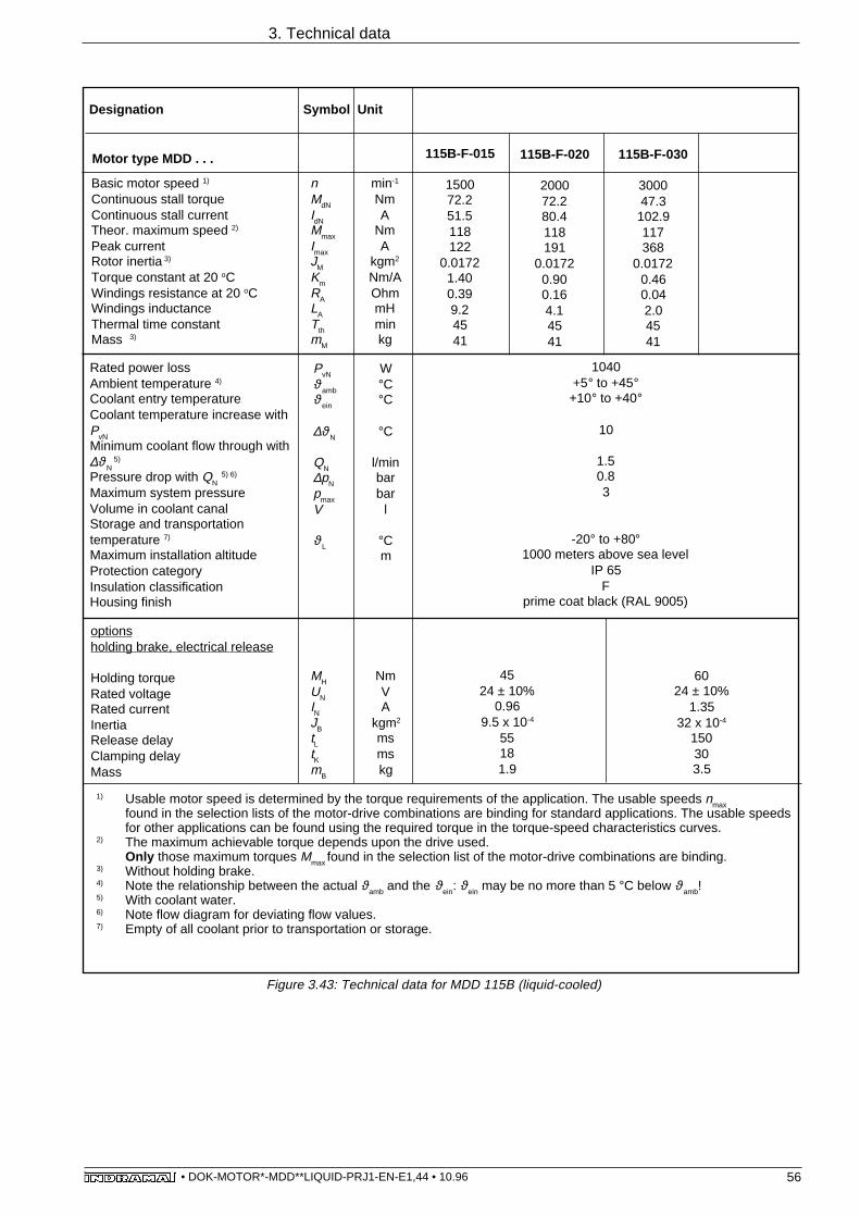
56• DOK-MOTOR*-MDD**LIQUID-PRJ1-EN-E1,44 • 10.96
Motor type MDD . . . 115B-F-020
200072.280.4118191
0.01720.900.164.14541
115B-F-030
300047.3
102.9117368
0.01720.460.042.04541
115B-F-015
150072.251.5118122
0.01721.400.399.24541
1040+5° to +45°+10° to +40°
10
1.50.83
-20° to +80°1000 meters above sea level
IP 65F
prime coat black (RAL 9005)
3. Technical data
PvN
ϑambϑein
∆ϑN
QN∆pN
pmax
V
ϑL
W°C°C
°C
l/minbarbar
l
°Cm
optionsholding brake, electrical release
Holding torqueRated voltageRated currentInertiaRelease delayClamping delayMass
MH NmUN VIN AJB kgm2
tL mstK msmB kg
1) Usable motor speed is determined by the torque requirements of the application. The usable speeds nmaxfound in the selection lists of the motor-drive combinations are binding for standard applications. The usable speedsfor other applications can be found using the required torque in the torque-speed characteristics curves.
2) The maximum achievable torque depends upon the drive used.Only those maximum torques Mmax found in the selection list of the motor-drive combinations are binding.
3) Without holding brake.4) Note the relationship between the actual ϑamb and the ϑein: ϑein may be no more than 5 °C below ϑamb!5) With coolant water.6) Note flow diagram for deviating flow values.7) Empty of all coolant prior to transportation or storage.
Rated power lossAmbient temperature 4)
Coolant entry temperatureCoolant temperature increase withPvNMinimum coolant flow through with∆ϑN
5)
Pressure drop with QN 5) 6)
Maximum system pressureVolume in coolant canalStorage and transportationtemperature 7)
Maximum installation altitudeProtection categoryInsulation classificationHousing finish
Basic motor speed 1)
Continuous stall torqueContinuous stall currentTheor. maximum speed 2)
Peak currentRotor inertia 3)
Torque constant at 20 oCWindings resistance at 20 oCWindings inductanceThermal time constantMass 3)
nMdN
IdNMmax
ImaxJM
Km
RALA
TthmM
min-1
NmA
NmA
kgm2
Nm/AOhmmHminkg
Symbol UnitDesignation
4524 ± 10%
0.969.5 x 10-4
55181.9
6024 ± 10%
1.3532 x 10⁻⁴
150303.5
Figure 3.43: Technical data for MDD 115B (liquid-cooled)

57• DOK-MOTOR*-MDD**LIQUID-PRJ1-EN-E1,44 • 10.96
Motor type MDD . . . 115C-F-020
200089.397.9146232
0.02220.910.123.54552
115C-F-030
300062.8
102.9146346
0.02220.610.051.34552
115C-F-015
150089.376.3146181
0.02221.170.215.24552
1190+5° to +45°+10° to +40°
10
1.70.93
-20° to +80°1000 meters above sea level
IP 65F
prime coat black (RAL 9005)
3. Technical data
Rated power lossAmbient temperature 4)
Coolant entry temperatureCoolant temperature increase withPvNMinimum coolant flow through with∆ϑN
5)
Pressure drop with QN 5) 6)
Maximum system pressureVolume in coolant canalStorage and transportationtemperature 7)
Maximum installation altitudeProtection categoryInsulation classificationHousing finish
optionsholding brake, electrical release
Holding torqueRated voltageRated currentInertiaRelease delayClamping delayMass
MH NmUN VIN AJB kgm2
tL mstK msmB kg
1) Usable motor speed is determined by the torque requirements of the application. The usable speeds nmaxfound in the selection lists of the motor-drive combinations are binding for standard applications. The usable speedsfor other applications can be found using the required torque in the torque-speed characteristics curves.
2) The maximum achievable torque depends upon the drive used.Only those maximum torques Mmax found in the selection list of the motor-drive combinations are binding.
3) Without holding brake.4) Note the relationship between the actual ϑamb and the ϑein: ϑein may be no more than 5 °C below ϑamb!5) With coolant water.6) Note flow diagram for deviating flow values.7) Empty of all coolant prior to transportation or storage.
Basic motor speed 1)
Continuous stall torqueContinuous stall currentTheor. maximum speed 2)
Peak currentRotor inertia 3)
Torque constant at 20 oCWindings resistance at 20 oCWindings inductanceThermal time constantMass 3)
nMdN
IdNMmax
Imax
JMKm
RALA
Tth
mM
min-1
NmA
NmA
kgm2
Nm/AOhmmHminkg
W°C°C
°C
l/minbarbar
l
°Cm
PvN
ϑambϑein
∆ϑN
QN∆pN
pmax
V
ϑL
Symbol UnitDesignation
4524 ± 10%
0.969.5 x 10-4
55181.9
6024 ± 10%
1.3532 x 10⁻⁴
150303.5
Figure 3.44: Technical data for MDD 115C (liquid-cooled)

58• DOK-MOTOR*-MDD**LIQUID-PRJ1-EN-E1,44 • 10.96
Motor type MDD . . .
1240+5° to +45°+10° to +40°
10
1.81.03
-20° to +80°1000 meters above sea level
IP 65F
prime coat black (RAL 9005)
3. Technical data
PvN
ϑambϑein
∆ϑN
QN∆pN
pmax
V
ϑL
W°C°C
°C
l/minbarbar
l
°Cm
optionsholding brake, electrical release
Holding torqueRated voltageRated currentInertiaRelease delayClamping delayMass
MH NmUN VIN AJB kgm2
tL mstK msmB kg
) Usable motor speed is determined by the torque requirements of the application. The usable speeds nmaxfound in the selection lists of the motor-drive combinations are binding for standard applications. The usable speedsfor other applications can be found using the required torque in the torque-speed characteristics curves.
2) The maximum achievable torque depends upon the drive used.Only those maximum torques Mmax found in the selection list of the motor-drive combinations are binding.
3) Without holding brake.4) Note the relationship between the actual ϑamb and the ϑein: ϑein may be no more than 5 °C below ϑamb!5) With coolant water.6) Note flow diagram for deviating flow values.7) Empty of all coolant prior to transportation or storage.
Rated power lossAmbient temperature 4)
Coolant entry temperatureCoolant temperature increase withPvNMinimum coolant flow through with∆ϑN
5)
Pressure drop with QN 5) 6)
Maximum system pressureVolume in coolant canalStorage and transportationtemperature 7)
Maximum installation altitudeProtection categoryInsulation classificationHousing finish
Basic motor speed 1)
Continuous stall torqueContinuous stall currentTheor. maximum speed 2)
Peak currentRotor inertia 3)
Torque constant at 20 oCWindings resistance at 20 oCWindings inductanceThermal time constantMass 3)
nMdN
IdNMmax
ImaxJM
Km
RALA
TthmM
min-1
NmA
NmA
kgm2
Nm/AOhmmHminkg
Symbol UnitDesignation
4524 ± 10%
0.969.5 x 10-4
55181.9
Figure 3.45: Technical data for MDD 115D (liquid-cooled)
115D-F-015
150010873.2177173
0.02711.480.256.49060
115D-F-020
200076.1
102.9177347
0.02710.740.061.79060
6024 ± 10%
1.3532 x 10⁻⁴
150303.5

59• DOK-MOTOR*-MDD**LIQUID-PRJ1-EN-E1,44 • 10.96
3.4.2. Torque-speed characteristics curves for MDD 115
3. Technical data
Figure 3.46: Torque-speed characteristics curves for MDD 115A
MDD 115A-Fwith 3000 min-1
MDD 115A-Fwith 2000 min-1
MDD 115A-Fwith 1500 min-1
DGMDD115A
00 1000
20
40
80
60
500 1500
87.1
2000 2500
10
30
70
50
90
[4] [3] [1][5] [2]
42
00 1000
20
40
80
60
500 1500
87.1
2000 2500
10
30
70
50
90
41.6
3000 3500 4000
[4] [3] [1][5] [2]
00
n/min-1
M/N
m
1000
20
40
80
60
500 1500
87.1
10
30
70
50
90
42
[4] [3] [1][5] [2]
n/min-1
M/N
m
n/min-1
M/N
m

60• DOK-MOTOR*-MDD**LIQUID-PRJ1-EN-E1,44 • 10.96
3. Technical data
Figure 3.47: Torque-speed characteristics curves for MDD 115B
MDD 115B-Fwith 3000 min-1
MDD 115B-Fwith 2000 min-1
MDD 115B-Fwith 1500 min-1
DGMDD115B
00
n/min-1
M/N
m
1000
20
40
80
60
500 1500
100
120 118.2
[4] [3] [1][5] [2]
00 1000
20
40
80
60
500 1500
100
120 118.2
[4] [3] [1][5] [2]
72.2
72.2
2000
00 1000
20
40
80
60
500 1500
100
120 118.1
47.3
2000
[4] [3] [1][5] [2]
30002500 3500 4000
n/min-1
M/N
m
n/min-1
M/N
m

61• DOK-MOTOR*-MDD**LIQUID-PRJ1-EN-E1,44 • 10.96
3. Technical data
Figure 3.48: Torque-speed characteristics curves for MDD 115C
MDD 115C-Fwith 3000 min-1
MDD 115C-Fwith 2000 min-1
MDD 115C-Fwith 1500 min-1
DGMDD115C
00
n/min-1
M/N
m
1000
20
40
80
60
500 1500
100
120
146.1
[4] [3] [1][5] [2]
140
89.3
00 1000
20
40
80
60
500 1500
100
120
146.2
140
89.3
[4] [3] [1][5] [2]
2000
00 1000
20
40
80
60
500 1500
100
120
146.2
140
62.8
2000 2500 3000
[4] [3] [1][5] [2]
n/min-1
M/N
m
n/min-1
M/N
m

62• DOK-MOTOR*-MDD**LIQUID-PRJ1-EN-E1,44 • 10.96
3. Technical data
MDD 115D-Fwith 2000 min-1
MDD 115D-Fwith 1500 min-1
DGMDD115D
00
n/min-1
M/N
m
1000
20
40
80
60
500 1500
100
120
140
160
180 177.3
[4] [3] [1][5] [2]
108
00 1000
20
40
80
60
500 1500
100
120
140
160
180 177.2
[4] [3] [1][5] [2]
2000 2500
76.1
n/min-1
M/N
m
Figure 3.49: Torque-speed characteristics curves for MDD 115D

63• DOK-MOTOR*-MDD**LIQUID-PRJ1-EN-E1,44 • 10.96
3.4.3. MDD 115 - shaft load
Figure 3.51: Radial force
Faxial = 0.35 • Fradial
Faxial
- permissible axial force
Fradial
- permissible radial force
Axial force Faxial
Radial force Fradial
Figure 3.50: Shaft load
3. Technical data
Faxial
Fradial
x
FAMDD115WEL
20 40 x/mm1000
1500
2000
2500
3000
naverage
500 min-1
1000 min-1
2000 min-1
3000 min-1
4000 min-1
6000 min-1
Fra
dial
/N
5000 min-1
60
Fradial - radial force as a function of distance, x, and average speed, naverage
output shaft without keyway limit with output shaft with keyway per DIN 6885, sh.1x - distance xnaverage - average servo motor speed (arithmetically determined)
Calculations based on:30 000 operating hours as nominalbearing lifespanL10h
Bearing lifespan drops with higherradial loads, Fload, as follows:L10h = (Fradial /Fload)3 • 30,000 hrs. DGMDD115RAD
3500
4000
10 30 50

64• DOK-MOTOR*-MDD**LIQUID-PRJ1-EN-E1,44 • 10.96
3.4.4. Maßangaben MDD 115
3. Technical data
145
1E
36
E
E
F Feedback connector:Not supplied with motor.
Name Connector Dim. F straight elbow
INS 510 INS 511
INS 512 112 INS 513 110
A Table:
B position accuracy per tolerance R DIN 42 955
C
D
center drill hole DS M12 per DIN 332, sh. 2
E Motor power connector:Not supplied with motor.
Table:
108
D
∅13
0 j6
B
R1
76
∅98
3
27S5
A
F
ø38
k6
C
4
18
58
45°
45°
1416
0
25°
193
245
215
F
M12-28
F
X
4
E
137
52
E
E
E
1) Larger with some options. The applicable dimension is given with the option.
Flange determines mounting mode• per design B5 (drill hole in flange)• per design B14 (windings in flange)
165±0.2
4 x M10 - 15
Size Dim.A 1)
MDD 115 A 359 MDD 115 B 409 MDD 115 C 459 MDD 115 D 509
2
General dimensions:
View X:
G 1/8"
88
92
E
A
MBMDD115A
Z
Table:
Type S5
INS 172 62.5
Dim.
Figure 3.52: General data on MDD 115 (liquid-cooled)
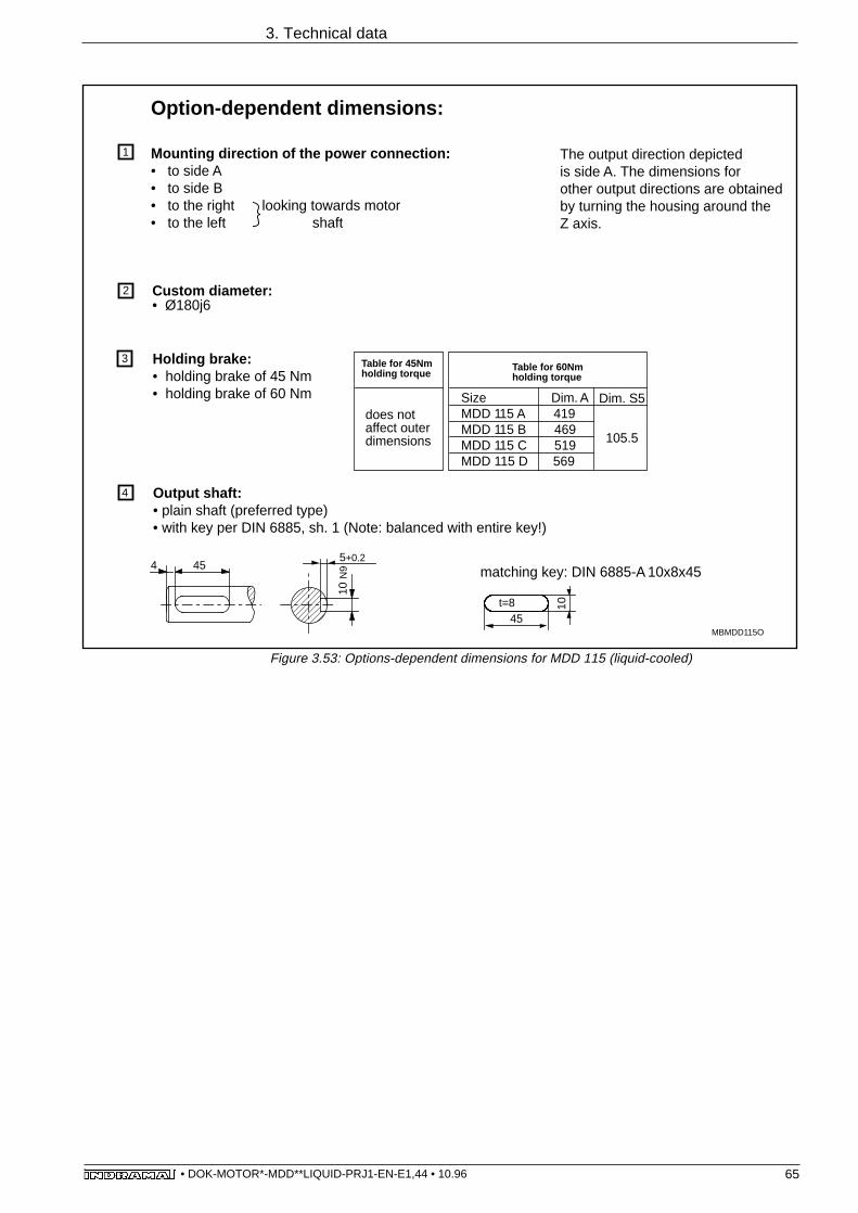
65• DOK-MOTOR*-MDD**LIQUID-PRJ1-EN-E1,44 • 10.96
3. Technical data
MBMDD115O
45
10t=8
455+0.2
10 N
9
1 Mounting direction of the power connection:• to side A• to side B• to the right looking towards motor• to the left shaft
3
Output shaft:• plain shaft (preferred type)• with key per DIN 6885, sh. 1 (Note: balanced with entire key!)
4
matching key: DIN 6885-A 10x8x454
Holding brake: • holding brake of 45 Nm • holding brake of 60 Nm
2 Custom diameter:• Ø180j6
Size Dim. AMDD 115 A 419MDD 115 B 469MDD 115 C 519MDD 115 D 569
Table for 60Nmholding torque
Dim. S5
105.5
does not affect outer dimensions
Table for 45Nmholding torque
Option-dependent dimensions:
The output direction depictedis side A. The dimensions forother output directions are obtainedby turning the housing around theZ axis.
Figure 3.53: Options-dependent dimensions for MDD 115 (liquid-cooled)

66• DOK-MOTOR*-MDD**LIQUID-PRJ1-EN-E1,44 • 10.96
3.4.5. MDD 115 - type codes
3. Technical data
1. DesignationMotor for digital drives MDD
2. Motor size 115
3. Motor length A, B, C, D
4. Housing:for liquid-cooling F
5. Rated speed1500 min -1 0152000 min -1 0203000 min -1 030 1)
6. Balance class N per DIN ISO 2373 N R per DIN ISO 2373 R
7. Shaft end on side B standard (without second shaft end) 2
8. Motor feedback digital servo feedback L digital servo feedback with integrated multiturn encoder M
9. Centering diameterø130 mm 130ø180 mm 180
10. Output shaft plain shaft G shaft with keyway per DIN 6885 Sh. 1 P
11. Output direction of power connectionTo side ATo side BTo the right(looking towards shaft, housing on top) RTo the left(looking towards shaft, housing on top) L
12. Holding brakeno holding brake 0with holding brake of 45.0 Nm 1with holding brake of 60.0 Nm 2
13. Custom versionDetermined and documented by INDRAMAT with custom numberField 13 does not apply to standard motors
Type codes: Example: M D D 1 1 5 B - F - 0 2 0 - N 2 L - 1 3 0 G B 0 / S 0 0 0
1) Not with motor length „D“
Figure 3.54: Options for MDD 115 (liquid-cooled)

67• DOK-MOTOR*-MDD**LIQUID-PRJ1-EN-E1,44 • 10.96
4. Electrical power connections
4. Electrical power connections
4.1. Terminal diagram
Figure 4.1: Power connections
1 4)
2 4)
3 4)
A1
A2
A3
M3
X)
powersupply
GNYE 4)
5)
Motortemperaturemonitoring1)
ϑ
↑↑ H
E
F
G
A
B
C
D
7)7)
6)
U
+
↑↓
-
6 or BN 4)
5 or WH 4)
7 or RD 4)
8 or BK 4)
Motorholdingbrake 2)0VL
+24V
5)
power connector INS 108 or INS 172
power connector INS 108 3)
(view onto soldering or crimped side of connector)
power connector INS 172 3)
(view onto soldering or crimped side of connector)
GA
B
C
HF
E
D
E
G
JF
B
C D
H
A
1) recommended conductor diameter minimum 0.75mm2 (or AWG 18),connection to drive
2) holding brake voltage on the motor +24 V, ±10%; recommended conductor diameter minimum 0.75 mm2 (or AWG 18),
connection to drive3) finishing guidelines for motor power connector INS 108 or INS 172
see separate cable documentation, doc. no. 209-0050-4399-XX4) core designations for INDRAMAT cables5) shield in motor power cable to be connected to drive6) see Table in Figure 4.2 for diameters7) When operating the machine or plant in residential or light industrial areas, it may be
necessary to shield the power lines to maintain the values for transmission ofinterference (rf interference suppression). The motor power connector is groundedvia the PG screw.
X) connection to drive
flange socket IN 220 or IN 192on the motor

68• DOK-MOTOR*-MDD**LIQUID-PRJ1-EN-E1,44 • 10.96
INDRAMAT motor power cableServo motor MDD ...
090 A-F-020090 A-F-030090 A-F-040090 B-F-020090 B-F-030090 B-F-040090 C-F-020090 C-F-030090 C-F-040
093 A-F-020093 A-F-030093 A-F-040093 A-F-060093 B-F-020093 B-F-030093 B-F-040093 B-F-060093 C-F-020093 C-F-030093 C-F-040093 C-F-060093 D-F-015093 D-F-020093 D-F-030093 D-F-040
112 A-F-015112 A-F-020112 A-F-030112 A-F-040112 B-F-015112 B-F-020112 B-F-030112 B-F-040112 C-F-015112 C-F-020112 C-F-030112 C-F-040112 D-F-015112 D-F-020112 D-F-030112 D-F-040
6.19.5
14.412.819.325.618.530.037.0
15.827.736.157.226.237.356.872.533.350.070.386.040.051.068.084.0
12.718.026.234.822.631.843.163.633.945.465.784.045.366.684.084.0
Minimum diameterpower connection* (mm2) (AWG) 1)
0.751.01.51.52.54.02.56.0
10.0
2.54.06.0
16.04.0
10.016.025.06.0
10.025.025.010.016.025.025.0
1.52.54.06.04.06.0
10.016.06.0
10.016.025.010.016.025.025.0
4.2. Connector to cable allocation
crimpingtype 2)
------
INS 108/02INS 108/02INS 108/03INS 108/04INS 108/03INS 172/06INS 172/10
INS 108/03INS 108/04INS 172/06INS 172/16INS 108/04INS 172/10INS 172/16
---INS 172/06INS 172/10
------
INS 172/10INS 172/16
------
INS 108/02INS 108/03INS 108/04INS 172/06INS 108/04INS 172/06INS 172/10INS 172/16INS 172/06INS 172/10INS 172/16
---INS 172/10INS 172/16
------
INS 108/06INS 108/06INS 108/06INS 108/06INS 108/06INS 108/06INS 108/06INS 172/25INS 172/25
INS 108/06INS 108/06INS 172/25INS 172/25INS 108/06INS 172/25INS 172/25INS 172/25INS 172/25INS 172/25INS 172/25INS 172/25INS 172/25INS 172/25INS 172/25INS 172/25
INS 108/06INS 108/06INS 108/06INS 172/25INS 108/06INS 172/25INS 172/25INS 172/25INS 172/25INS 172/25INS 172/25INS 172/25INS 172/25INS 172/25INS 172/25INS 172/25
solderingtype 2)
Motor power connector
0.751.51.51.52.54.02.56.0
10.0
2.54.06.0
16.04.0
10.016.025.06.0
10.025.025.010.016.025.025.0
1.52.54.06.04.06.0
10.025.06.0
10.016.025.010.016.025.025.0
INK 653INK 650INK 650INK 650INK 602INK 603INK 602INK 604INK 605
INK 602INK 603INK 604INK 606INK 603INK 605INK 606INK 607INK 604INK 605INK 607INK 607INK 605INK 606INK 607INK 607
INK 650INK 602INK 603INK 604INK 603INK 604INK 605INK 607INK 604INK 605INK 606INK 607INK 605INK 606INK 607INK 607
INK 253INK 250INK 250INK 250INK 202INK 203INK 202INK 204INK 205
INK 202INK 203INK 204INK 206INK 203INK 205INK 206INK 207INK 204INK 205INK 207INK 207INK 205INK 206INK 207INK 207
INK 250INK 202INK 203INK 204INK 203INK 204INK 205INK 207INK 204INK 205INK 206INK 207INK 205INK 206INK 207INK 207
------------
INK 402 3)
INK 403 4)
INK 402 3)
INK 404 4)
INK 405
INK 402 3)
INK 403 4)
INK 404INK 406
INK 403 4)
INK 405INK 406INK 407INK 404INK 405INK 407INK 407INK 405INK 406INK 407INK 407
---INK 402 3)
INK 403 4)
INK 404INK 403 4)
INK 404INK 405INK 407INK 404INK 405INK 406INK 407INK 405INK 406INK 407INK 407
181816161412121010
1412108
101064
108638643
16141210101084
108638633
* Motor phase currents and power connections apply to S1 continuous operation
4. Electrical power connections
1) Minimum diameter of power connection per EN 60 204, section 1, table 5, column C or E, or UL 508 table 50.2. butat least 0.75 mm2 (or AWG 18); cable per UL 508 can only be soldered to the motor power connector, not crimped.
2) Data following the slash define the type of bushing of the motor power connector for either crimping or soldering.3) Use INS 108/04 crimped, for motor power connector.4) Only soldered motor power connector.
Figure 4.2: Allocation of connector to cables for the power connections
Motorphase
current* (A) no shield with dia-standard flexible shield meter
type type type (mm 2)

69• DOK-MOTOR*-MDD**LIQUID-PRJ1-EN-E1,44 • 10.96
Servo motor MDD ...
115 A-F-015115 A-F-020115 A-F-030115 B-F-015115 B-F-020115 B-F-030115 C-F-015115 C-F-020115 C-F-030115 D-F-015115 D-F-020
32.443.265.842.065.784.062.380.084.059.884.0
6.010.016.010.016.025.016.025.025.016.025.0
INS 172/06INS 172/10INS 172/16INS 172/10INS 172/16
---INS 172/16
------
INS 172/16---
INS 172/25INS 172/25INS 172/25INS 172/25INS 172/25INS 172/25INS 172/25INS 172/25INS 172/25INS 172/25INS 172/25
solderingtype 2)
Motor power connector
6.010.016.010.016.025.016.025.025.016.025.0
INK 604INK 605INK 606INK 605INK 606INK 607INK 606INK 607INK 607INK 606INK 607
INK 204INK 205INK 206INK 205INK 206INK 207INK 206INK 207INK 207INK 206INK 207
INK 404INK 405INK 406INK 405INK 406INK 407INK 406INK 407INK 407INK 406INK 407
108686364363
INDRAMAT motor power cableMotorphase
current * (A)
Minimum diameterpower connection * (mm2) (AWG) 1)
* Motor phase current and connection diameters apply to S1 continuous operation
1) Minimum diameter of power connection per EN 60 204, section 1, table 5, column C or Eor UL 508 table 50.2. butat least 0.75 mm2 (or AWG 18); cable per UL 508 can only be soldered to the motor power connector, not crimped.
2) Data following the slash define the type of bushing of the motor power connector for either crimping or soldering.
4. Electrical power connections
Figure 4.3: Allocation of connector to cables for the power connections
crimpingtype 2)
without shield with dia-standard flexible shield meter type type type (mm 2)

70• DOK-MOTOR*-MDD**LIQUID-PRJ1-EN-E1,44 • 10.96
4.3. Motor power connectors
Connector power core
Crimping Solderingstrain relief 1)
Connectorcontrolcore 2)
(mm2)
powercore
(mm2)
strain relief 1)
INS 108/02
INS 108/03
INS 108/04
1.5
2.5
4.0
1.5
1.5
1.5
250650
202602
203402603
225 404257 1214)
219 857254 917
218 767227 526253 053
cableINK
part number
controlcore 2)
maximum
partnumber
maximum connectiondiameter
cableINK
1) Threaded PG joints should be mounted into the motor power connector to ensure trouble-free operation. They are not delivered withthe motor power connector. INDRAMAT makes these parts available. They can be ordered to match the cable types by using theabove listed parts number.
2) For monitoring of motor holding brake and temperature.3) Further reduction requires part number 220 4744) Further reduction requires part number 252 6525) Further reduction requires part number 252 6526) Further reduction requires parts 220 474 and 221 024
203204205206207
403404405406407
603604605606607
220874 3)
220874 3)
220472 3)
220472 3)
220473
228864 3)
220874 3)
221554 3)
220472 3)
220472 3)
253053 6)
253053 6)
257120 6)
252653252653
6.0
10.0
16.0
1.5
1.5
1.5
INS 172/06
INS 172/10
INS 172/16
204404604
205405605
206406606
220874 3)
228864 3)
253053 3)
220472 3)
221554 3)
257120 3)
220472 3)
221554 3)
252653 3)
0.75 - 6.0mm2
1.5mm2
225 404225 404219 857218 767218 767
227 526219 857218 767
252 651 4)
257 121 3)
254 917253 053253 053
253250202203204
402403404
653650602603604
AWG18 - 10
AWG16
INS 108/06
4.0 - 25.0mm2
1.5mm2
AWG10 - 3
AWG16
INS 172/25
Pg 21 1)
INS 172
INS 108
Pg 36 1)
Figure 4.4: Motor power connectors
4. Electrical power connections
maximum connectiondiameter

71• DOK-MOTOR*-MDD**LIQUID-PRJ1-EN-E1,44 • 10.96
4. Electrical power connections
4.4. Motor power cables - technical data
90110200270300380390430140160175220250270100120140180195240280270
0.110.190.470.570.671.101.331.700.270.370.500.741.101.520.250.390.590.600.811.101.401.73
minimum bending radius
fixed routing flexible routing 2)
(mm) (mm)
typepower core
diameter(mm 2)
controlcore 1)
diameter(mm 2)
totalshield
powercable
diameter(mm)
specificweightkg/m
5070
1201201202002202408595
105130150180708085
110120150160190
10 ± 111 ± 1
17.3 ± 0.518.6 ± 0.5
20 ± 0.626 ± 0.727 ± 0.7
30.5 ± 0.813.5 ± 115.5 ± 118 ± 1
21.5 ± 125.0 ± 126.0 ± 19.6 ± 0.312.2 ± 0.414.8 ± 0.516.9 ± 0.518.8 ± 0.623.8 ± 0.528.2 ± 0.627.6 ± 0.5
0.340.751.51.51.51.51.51.5
0.750.75 or 1.00.75 or 1.00.75 or 1.0
1.01.5
0.340.750.75
0.75 or 1.00.75 or 1.00.75 or 1.0
1.01.5
0.751.52.54.06.010.016.025.02.54.06.010.016.025.00.751.52.54.06.010.016.025.0
INK 253INK 250INK 202INK 203INK 204INK 205INK 206INK 207INK 402INK 403INK 404INK 405INK 406INK 407INK 653INK 650INK 602INK 603INK 604INK 605INK 606INK 607
––––––––––––––++++++++
1) For monitoring of holding brake and temperature2) Working life equals more than 500,000 bending loads
Protection category cable to connector transition IP 65
chemical characteristics absolute resistance to mineral oils andgreases, hydrolysis resistance, siliconeand halogen free
permissible ambient temperaturefor operation and storages from -30 °C to +80 °C
cable surface does not adhere, prevents sticking in dragchains
cable length maximum 75 meters
General information
Figure 4.6: General data on the motor power cables
Figure 4.5: Type-dependent data of the motor power connection

72• DOK-MOTOR*-MDD**LIQUID-PRJ1-EN-E1,44 • 10.96
4.5. Ready-made motor power cables
Motorpower
connectorMotor typeMDD…
plug adapter with coupler
unit 1)
Cable ends for
intermediate clamp toclamping strip or
connectedto drive with clamps
(e.g., DKS, DDS 3, DKC)
connected to drive with bolts
(e.g., DDS 2)
Motorpowercable
powercore
diameter
mm2
1) for mounting matching connector: motor power connectorDB_KONFMOTLEIST
090A-F-020090A-F-030090A-F-040090B-F-020090B-F-030090B-F-040090C-F-020090C-F-030090C-F-040
093A-F-020093A-F-030093A-F-040093A-F-060093B-F-020093B-F-030093B-F-040093B-F-060093C-F-020093C-F-030093C-F-040093C-F-060093D-F-015093D-F-020093D-F-030093D-F-040
112A-F-015112A-F-020112A-F-030112A-F-040112B-F-015112B-F-020112B-F-030112B-F-040112C-F-015112C-F-020112C-F-030112C-F-040112D-F-015112D-F-020112D-F-030112D-F-040
115A-F-015115A-F-020115A-F-030115B-F-015115B-F-020115B-F-030115C-F-015115C-F-020115C-F-030115D-F-015115D-F-020
0.751.51.51.52.54.02.56.0
10.0
2.54.06.0
16.04.0
10.016.025.06.0
10.025.025.010.016.025.025.0
1.52.54.06.04.06.0
10.025.06.0
10.016.025.010.016.025.025.0 6.0
10.016.010.016.025.016.025.025.016.025.0
IK• 011IK• 021IK• 021IK• 021IK• 041IK• 061IK• 041IK• 101IK• 121
IK• 041IK• 061IK• 101IK• 141IK• 061IK• 121IK• 141IK• 161IK• 101IK• 121IK• 161IK• 161IK• 121IK• 141IK• 161IK• 161
IK• 021IK• 041IK• 061
IK• 061IK• 101IK• 121
IK• 101IK• 121IK• 141IK• 161IK• 121IK• 141IK• 161IK• 161
IK• 101IK• 121IK• 141IK• 121IK• 141IK• 161IK• 141IK• 161IK• 161IK• 141IK• 161
INS 108/06INS 108/06INS 108/02INS 108/02INS 108/03INS 108/04INS 108/03INS 172/06INS 172/10
INS 108/03INS 108/04INS 172/06INS 172/16INS 108/04INS 172/10INS 172/16INS 172/25INS 172/06INS 172/10INS 172/25INS 172/25INS 172/10INS 172/16INS 172/25INS 172/25
INS 108/02INS 108/03INS 108/04INS 172/06INS 108/04INS 172/06INS 172/10INS 172/16INS 172/06INS 172/10INS 172/16INS 172/25INS 172/10INS 172/16INS 172/25INS 172/25
INS 172/06INS 172/10INS 172/16INS 172/10INS 172/16INS 172/25INS 172/16INS 172/25INS 172/25INS 172/16INS 172/25
IK• 012IK• 022IK• 022IK• 022IK• 042IK• 062IK• 042IK• 102IK• 122
IK• 042IK• 062IK• 102IK• 142IK• 062IK• 122IK• 142IK• 162IK• 102IK• 122IK• 162IK• 162IK• 122IK• 142IK• 162IK• 162
IK• 022IK• 042IK• 062
IK• 062IK• 102IK• 122
IK• 102IK• 122IK• 142IK• 162IK• 122IK• 142IK• 162IK• 162
IK• 102IK• 122IK• 142IK• 122IK• 142IK• 162IK• 142IK• 162IK• 162IK• 142IK• 162
IK• 003IK• 023IK• 023IK• 023IK• 043IK• 063IK• 043IK• 108IK• 128
IK• 043IK• 063IK• 108IK• 148IK• 063IK• 128IK• 148IK• 168IK• 108IK• 128IK• 168IK• 168IK• 128IK• 148IK• 168IK• 168
IK• 023IK• 043IK• 063
IK• 063IK• 108IK• 128
IK• 108IK• 128IK• 148IK• 168IK• 128IK• 148IK• 168IK• 168
IK• 108IK• 128IK• 148IK• 128IK• 148IK• 168IK• 148IK• 168IK• 168IK• 148IK• 168
Figure 4.7: Ready-made motor power cables
4. Electrical power connections

73• DOK-MOTOR*-MDD**LIQUID-PRJ1-EN-E1,44 • 10.96
Ordering guidelines Example: IKL 001 / 12.0 Length in meters
L…standard cable with shield F…flexible cable without shield (not available in diameters 0.75
and 1.5 mm2)
G…cable with shield
(Available in increments of 0.5 meters after a length of five meters. Smallerlengths available upon request.)
4. Electrical power connections

74• DOK-MOTOR*-MDD**LIQUID-PRJ1-EN-E1,44 • 10.96
5. Electrical motor feedback connection
1
2
3
4
5
6
7
8
9
10
11
12
IN514 flange socket on motor
C-
C+
S+
FS
not assig.
SCL
0VM
not assig.
RD
BU
VT
GY
WH
Feedback connector INS..
tothedrive
Feedback connector INS . . .(looking towards soldering side of connector)Connection diameter: max. 1.0 mm 2
Feedback cable INK 209, 8x0.25 mm , 2x1.0 mm
2
S-
UG BN
BK
SDI
SDO
PK
BN
GN
2
1.0 mm
1.0 mm
0.25 mm
0.25 mm
0.25 mm
0.25 mm
0.25 mm
0.25 mm
0.25 mm
0.25 mm2
2
2
2
2
2
2
2
2
2
123
4 567
89
1011
12
APMOTFEEDB
If own cables are used, then execute connecting cores per Figure 5.1.Improper execution could cause operational problems.
5. Electrical motor feedback connection
5.1. Terminal diagram
Figure 5.1: Terminal diagram

75• DOK-MOTOR*-MDD**LIQUID-PRJ1-EN-E1,44 • 10.96
connector (straight)
Designation
connector (elbow)
connectors for all cables with outsidediameter of 6 to 10 mm
INS 512
INS 510
connectors forINDRAMAT cable INK 209
INS 513
INS 511
Figure 5.3: Technical data of feedback cable INK 209
5.2. Feedback connector
Figure 5.2: Feedback connector
5.3. Feedback cable - technical data
5. Electrical motor feedback connection
type designation INK 209
cable-connector transition protection category IP 65
cable diameter 8.8 mm
bending radius - fixed routing 40 mm
bending radius - flexible routing 90 mm(lifespan greater than 500,000 bending loads)
specific weight 0.102 kg/m
permissible ambient temperature foroperating and storage -30 °C to +80 °C
cable surface does not adhere, prevents sticking indrag chains
maximum cable length 75 meters
chemical characteristics absolute resistance to mineral oilsand greases, hydrolysis resistant,
silicone and halogen free

76• DOK-MOTOR*-MDD**LIQUID-PRJ1-EN-E1,44 • 10.96
5.4. Ready-made feedback cables
INS 513
INS 511
INDRAMATfeedback
cable
tyype designation forfeedback connectors
IKS 374 /…
IKS 375 /…
IKS 376 /…
IKS 377 /…
IKS 378 /…
IKS 379 /…
order designation forready-made
feedback cables
INS 453
INS 453
INS 516
INS 516
cable end
plug-inconnector
15-pinD-
subminiature
INS 513
INS 511
INK 209
INK 209
INK 209
INK 209
INK 209
INK 209
INS 513
INS 511
with ferrules to connect toterminal blocks 1)
with couplingmounts tomatching connector IN 513
1) To be avoided as could interfere with shield.
Figure 5.4: Ready-made feedback cables
Ordering guidelines Exanple: IKS 374 / 12.0
Length in meters
(Available in increments of 0.5 meters after five meter lengths. Shorter lengthsavailable upon request.)
5. Electrical motor feedback connection
connects todrive

77• DOK-MOTOR*-MDD**LIQUID-PRJ1-EN-E1,44 • 10.96
6. Coolant connections
The coolant connection can be executed as follows:
EKANSFL
motor hose nozzle hose hose clip
coupling with windings
coupling withthreaded joint
hose
clamp connectionwith windings
quick-coupler motor
hose nozzle
motorclamp connection
Connection type Sketch
hose
Figure 6.1: Possible liquid-cooling connections
These parts cannot presently be obtained from INDRAMAT.
The coolant supply systems can be made of either
• pipes, or,
• hoses.
Coolant supply lines
There is a considerable degree of pressure loss in a pipe coolantsupply system due to the re-routing points (e.g., 90 ° elbows) whichunavoidably occur in such a system. We therefore recommend theuse of a hose supply system.
When choosing a hose system, however, the pressure loss withinthe system must be taken into consideration. Thus, the insidediameter of the hose must equal at least 9mm and must narrowshortly before the point of connection to the motor in those caseswhere greater hose lengths are necessary.
6. Coolant connections

78• DOK-MOTOR*-MDD**LIQUID-PRJ1-EN-E1,44 • 10.96
Coolant The data listed in the documentation relates to water as coolant.
Further information on additives or other coolants are listed in thedocumentation, "Liquid coolant of INDRAMAT drive components".
A pressure drop under nominal conditions is given in the technical data.Should the flow of volume change
• because some other coolant is used, or,
• because regulating or adjusting devices are lacking,
then the pressure drop changes as depicted in the flow diagram.
Flow diagram
0 1 2 3 4 5
3.0
2.5
2.0
1.5
1.0
0.5
0
volume flow rate (l/min)
pres
sure
dro
p ∆
p (b
ar)
DGDURCHFLUSSflow diagram based on water at 20°C
Figure 6.2: Flow diagram for an MDD servo motor
Supplementary information on cooling systems can be found in thedocumentation entitled: "Liquid cooling of INDRAMAT drive components".
Supplementaryinformation
6. Coolant connections
Pressure drop

79• DOK-MOTOR*-MDD**LIQUID-PRJ1-EN-E1,44 • 10.96
7. Index
7. Index
AAmbient temperature 8Application 15
BBalance class 11
CCentering diameters 10Connector to cable allocation 68Construction 6Coolant 78Coolant connections 77Coolant supply lines 77
DDigital servo feedback 9Digital servo feedback with integrated multiturn a 9DSF 9DSF+MTG 9
EElbow connector 13Electrical motor feedback connection 74Electrical power connections 67Environmental conditions 8
FFeedback cable 75Feedback connector 12, 75Flow diagram 78
HHigh-dynamic applications 5High-precision applications 5Holding brake 11
IInstallation altitude 8
LLabelling the sides 7
MMDD 090 16MDD 093 27MDD 112 41MDD 115 55Motor feedback 6, 9Motor power cables 71Motor power connector 12Motor power connectors 70Mounting to the machine 7

80• DOK-MOTOR*-MDD**LIQUID-PRJ1-EN-E1,44 • 10.96
7. Index
MTG 9
OOperating curves 14Operating reliability 6Output direction of the power connection 10Output shaft 10
PPerformance data 6Performance overview 5Pressure drop 78Protection category 8
RReady-made feedback cables 76Ready-made motor power cables 72
SSpeed limiting values 14
TTechnical information 8Terminal diagram 12, 67, 74Torque limiting values 14Torque-speed characteristics curves 14

Indramat