MDA and Integration of Legacy Systems
85
MDA and Integration of Legacy Systems by Selo & Warsun Najib Masters Thesis in Information and Communication Technology Agder University College Grimstad, May 2003
Transcript of MDA and Integration of Legacy Systems

MDA and Integration of Legacy Systems
by
Selo & Warsun Najib
Masters Thesis in Information and Communication Technology
Agder University College
Grimstad, May 2003

MDA and Integration of Legacy Systems
ii
Abstract OMG’s Model Driven ArchitectureTM, MDATM, is the new paradigm of software development and a new way of writing specifications and developing applications, based on a platform-independent model (PIM). MDA divorces implementation details from business functions. Thus, it is not necessary to repeat the process of modeling of applications or system’s functionality and behavior each time a new technology comes along. With the MDA, it is easier to integrate the new applications with the old application that is already installed.
In the real time distributed telecommunication system, MDA addresses the challenge of constantly changing infrastructure and promotes application and component reuse and portability. The success of MDA depends highly on integration of legacy systems in a MDA context. This activity may include reengineering of code or transforming existing UML models to MDA context.
Objectives of our thesis are to study the possibility of developing platform independent models (PIM) from existing UML models, components specified by interfaces in CORBA IDL and implemented Erlang code. We also studied which aspects of the context system (a real-time distributed telecommunication application) that can be specified in a Platform Independent Model and which aspects are left for a Platform Specific Model (PSM) and coding. For this study purpose, we use some UML models, IDL interfaces, Erlang code and some use case diagrams in GSN system from Ericsson ‘s GPRS project.
XMI gives the possibility to perform model exchange and model transformation. Therefore, we used XMI to develop PIM from the existing UML model, CORBA IDL interface, and Erlang code in our case study. There are two possible PIMs we can develop for the GSN legacy systems (the existing UML model, CORBA IDL and Erlang code) that are, a structural specificationally complete PIM and a structural and external behavioral specificationally complete PIM.
We have developed a translator to translate CORBA IDL and Erlang code into a UML model represented in XMI. This model is a structural specificationally complete PIM since the model is structurally complete with model packaging, class, attribute, operation, operation’s argument, datatype, stereotype and dependencies. We have also made an XMI mixer to combine XMI generated by the translator (a structural specificationally complete PIM) with XMI generated from the existing UML models (that contain external behavioral aspects) in order to produce a structural and external behavioral specificationally complete PIM.
The result of our study reveals many problems with the reverse engineering of Erlang code that uses procedural programming concept. Nevertheless, we found some benefits of using MDA in software development of legacy systems. The documentation of the model is always up to date since we can reverse engineer the implemented code into model whenever we want. Even if generating a behavior complete PIM is difficult, we can have an updated structural complete PIM. Since documentation is in the high-level model and is platform independent, then it is possible to transform the model into multiple platforms or programming languages. We experienced that the success of the integration of the old applications with the new application is highly dependent on MDA tools.

MDA and Integration of Legacy Systems
iii
Preface This thesis is written for Ericsson in Grimstad and is performed to complete the Master of Science degree in Information and Communication Technology (ICT) at the Faculty of Engineering and Science, Agder University College (Høgskolen I Agder, HIA), Norway. We would like to thank Ericsson in Grimstad for providing the facilities so we were able to perform our case study. We would also like to thank Parastoo Mohagheghi at Ericsson and Jan P. Nytun at HiA for their guidance, advice and valuable help during the project. Last, we would like to thank our families for their support, attention and motivation during our three years of study in Norway.
S e l o Warsun Najib
Grimstad, Norway May 2003

MDA and Integration of Legacy Systems
iv
Table of Contents ABSTRACT..................................................................................................................................................II PREFACE................................................................................................................................................... III TABLE OF CONTENTS........................................................................................................................... IV LIST OF FIGURES ................................................................................................................................... VI LIST OF TABLES ..................................................................................................................................... VI 1 INTRODUCTION......................................................................................................................................1
1.1 THESIS INTRODUCTION ..........................................................................................................................1 1.2 LEGACY SYSTEM AT ERICSSON .............................................................................................................2 1.3 WORK/TASK DESCRIPTION....................................................................................................................2 1.4 LITERATURE REVIEW ............................................................................................................................2 1.5 REPORT OUTLINE ..................................................................................................................................3
2 SOFTWARE ENGINEERING AND LEGACY SYSTEM OF TELECOMMUNICATION APPLICATIONS...........................................................................................................................................4
2.1 SOFTWARE ENGINEERING......................................................................................................................4 2.1.1 Rational Unified Process ..............................................................................................................4 2.1.2 Software Development ..................................................................................................................8
2.2 LEGACY SYSTEMS IN THE TELECOMMUNICATION DOMAIN.................................................................12 2.3 SUMMARY ...........................................................................................................................................14
3 MODEL DRIVEN ARCHITECTURE...................................................................................................15 3.1 INTRODUCTION....................................................................................................................................15
3.1.1 The Unified Modeling Language™ (UML™) ............................................................................16 3.1.2 The Meta-Object Facility (MOF™)............................................................................................17 3.1.3 XML Metadata Interchange (XMI™) .........................................................................................17 3.1.4 Common Warehouse Meta-Model (CWM™)..............................................................................18 3.1.5 System Lifecycle - MOF, UML, CWM and XMI .........................................................................18 3.1.6 Modeling in MDA .......................................................................................................................19
3.2 PIM-PSM DEFINITION ........................................................................................................................19 3.2.1 PIM Definition ............................................................................................................................20 3.2.2 PSM Definition ...........................................................................................................................22 3.2.3 Model Mapping...........................................................................................................................24
3.3 DEVELOPING APPLICATIONS WITH MDA ............................................................................................26 3.3.1 MDA Structure............................................................................................................................26 3.3.2 Build Model Process...................................................................................................................26 3.3.3 Integration of Legacy Systems ....................................................................................................28 3.3.4 Interoperability ...........................................................................................................................28 3.3.5 Pervasive Services ......................................................................................................................28
3.4 THE CHALLENGE OF MDA IN REAL-TIME DISTRIBUTED TELECOMMUNICATION APPLICATIONS..........29 3.5 SUMMARY ...........................................................................................................................................30
4 PIM – PSM TRANSFORMATION........................................................................................................31 4.1 TRANSFORMATION PIM INTO PSM .....................................................................................................31
4.1.1 UML Profile................................................................................................................................32 4.1.2 UML Profile for CORBA ............................................................................................................33
4.2 REVERSE ENGINEERING.......................................................................................................................33 4.2.1 Conventional Reverse Engineering.............................................................................................33 4.2.2 Reverse Engineering in MDA .....................................................................................................35 4.2.3 Reverse Engineering Tools .........................................................................................................36
4.3 RESEARCH IN MODELS TRANSFORMATION..........................................................................................36 4.3.1 Introduction ................................................................................................................................36 4.3.2 Existing Approaches ...................................................................................................................37
4.4 AVAILABLE MDA TOOLS....................................................................................................................39

MDA and Integration of Legacy Systems
v
4.4.1 Telelogic Tau ..............................................................................................................................40 4.4.2 ArcStyler .....................................................................................................................................40 4.4.3 Objecteering ...............................................................................................................................41 4.4.4 Poseidon .....................................................................................................................................41 4.4.5 iUML...........................................................................................................................................42 4.4.6 Kabira.........................................................................................................................................42 4.4.7 UMT............................................................................................................................................43
4.5 VISIONS FOR THE FUTURE MDA TOOLS ..............................................................................................43 4.6 SUMMARY ...........................................................................................................................................45
5 CASE STUDY...........................................................................................................................................46 5.1 MODELS FOR CASE STUDY ..................................................................................................................46 5.2 GOALS, METHOD AND TOOLS USED ....................................................................................................49 5.3 CONSIDERED ASPECTS OF DEVELOPING A PIM ...................................................................................51
5.3.1 Aspects Specified in PIM ............................................................................................................51 5.3.2 Aspects Left for a PSM................................................................................................................52
5.4 XMI AS STANDARD FOR MODEL EXCHANGE ........................................................................................52 5.5 DEVELOPING PIM FROM ERLANG CODE, CORBA IDL AND THE EXISTING UML MODEL..................54
5.5.1 Developing PIM from Erlang Code............................................................................................54 5.5.2 Developing PIM from IDL Interfaces .........................................................................................59 5.5.3 Developing PIM from Existing UML Models .............................................................................60
5.6 SUMMARY ...........................................................................................................................................61 6 DISCUSSION ...........................................................................................................................................63
6.1 IS THE MODEL A PIM?.........................................................................................................................63 6.2 ADOPTION OF MDA AT ERICSSON.......................................................................................................63 6.3 FUTURE WORK: PIM GENERATOR AND UML TO ERLANG TRANSLATOR............................................65
7 CONCLUSION.........................................................................................................................................66 ABBREVIATIONS AND GLOSSARY.....................................................................................................67 REFERENCES............................................................................................................................................69 APPENDIX A THESIS DEFINITION......................................................................................................72 APPENDIX B GSN MODEL .....................................................................................................................73
B-1 GSN MODEL STRUCTURE...................................................................................................................73 B-2 GSN META-MODEL.............................................................................................................................73
APPENDIX C CORBA IDL: MAC.IDL...................................................................................................73 APPENDIX D ERLANG CODE: MACAL.ERL .....................................................................................73 APPENDIX E XMI AND UML .................................................................................................................73
E-1 XMI of UML Model for Model Exchange .....................................................................................73 E-2.a XMI of MPS Subsystem ..............................................................................................................73 E-2.b UML Model of MPS Subsystem..................................................................................................73 E-3.a XMI of NCS Subsystem ..............................................................................................................73 E-3.b UML Model of NCS Subsystem..................................................................................................73 E-4.a XMI of MPS and NCS Combination...........................................................................................73 E-4.b UML Model of MPS and NCS Combination ..............................................................................73
APPENDIX F MODEL TESTING ............................................................................................................73 APPENDIX G ERLANG TO XMI TRANSLATOR................................................................................73
G-1 CLASS DIAGRAM................................................................................................................................73 G-2 IMPLEMENTATION CODE ....................................................................................................................74 G-3 DOCUMENTATION OF ERLANG TO XMI TRANSLATOR........................................................................74

MDA and Integration of Legacy Systems
vi
List of Figures Figure 1 GSN Rational Unified Process [31] [27] ...............................................................8 Figure 2 System Construction Paradigm [2] .......................................................................9 Figure 3 Software systems structure [31]..........................................................................13 Figure 4 The Core of MDA [12] .......................................................................................15 Figure 5 Abstraction levels of PIM and PSM ...................................................................20 Figure 6 PSM CORBA......................................................................................................22 Figure 7 CORBA IDL .......................................................................................................23 Figure 8 Models Transformation [8] .................................................................................25 Figure 9 Development process of MDA model ................................................................27 Figure 10 Source analysis and recoding [25] ....................................................................34 Figure 11 Conventional reverse engineering translator [25].............................................35 Figure 12 MDA Concept for reverse engineering [25] .....................................................36 Figure 13 UMT tool ..........................................................................................................43 Figure 14 GPRS System [31] ............................................................................................46 Figure 15 Design and Implementation view of GSN Meta model [31], ...........................47 Figure 16 High level package of GSN model [31]............................................................48 Figure 17 Analysis and Development used by Ericsson [31] ...........................................49 Figure 18 PIM Development Method ...............................................................................50 Figure 19 XMI for model exchange between tools...........................................................53 Figure 20 UML model made by Poseidon ........................................................................53 Figure 21 Model opened by UMT.....................................................................................53 Figure 22 Structure of Erlang Procedures .........................................................................55 Figure 23 Example of Erlang module ...............................................................................55 Figure 24 Java Version of attach.erl..................................................................................56 Figure 25 IDL version of attach.erl ...................................................................................56 Figure 26 UML class of attach.erl.....................................................................................57 Figure 27 Erlang to XMI Translator..................................................................................57 Figure 28 Structure of UML..............................................................................................58 Figure 29 eeee1.erl class ...................................................................................................58 Figure 30 Dependencies ....................................................................................................59 Figure 31 example.idl file .................................................................................................59 Figure 32 Advanced Translator-1......................................................................................60 Figure 33 More complete eeee1.erl class ..........................................................................60 Figure 34 XMI mixer and PIM generator .........................................................................61 Figure 35 Software Development based on legacy system in Ericsson ............................64
List of Tables Table 1 Some UML tools that provide round trip engineering [19] .................................36 Table 2 XMI and UML version of MDA Tools................ Error! Bookmark not defined.

MDA and Integration of Legacy Systems
1
1 Introduction 1.1 Thesis introduction
MDA addresses the complete life cycle of designing, deploying, integrating, and managing applications as well as data using open standards. MDA-based standards enable organizations to integrate whatever they already have in place with what they build today and what they build tomorrow [8]. Most importantly, MDA enables the creation of standardized Domain Models for specific vertical industries [6]. These standardized models can be realized for multiple platforms now and in the future, easing multiple platform integration issues and protecting IT investments against the uncertainty of changing fashions in platform technology. MDA divorces implementation details from business functions. Thus, it is not necessary to repeat the process of modeling an application or system’s functionality and behavior each time a new technology comes along. The following are some of the benefits of MDA [9]:
• Reduced cost throughout the application life-cycle • Reduced development time for new applications • Increased return on technology investments • Rapid inclusion of emerging technology benefits into their existing systems
MDA provides a solid framework that frees system infrastructures to evolve in response to a never-ending parade of platforms, while preserving and leveraging existing technology investments. It enables system integration strategies that are better, faster and cheaper. Although promising MDA tools are appearing at the beginning of 2003, in the perception of the mainstream developer, there is little in terms of concrete tools that actually support MDA beyond traditional UML modeling and skeleton-class generation. Evolving tools provide features to define and instantiate design patterns, but most of these tools still expose the user to UML models at the implementation level. One weakness in the current traditional UML modeling is that the gap between business abstract models and the concrete implementation is big. MDA introduce PSM as a way to bridge this gap.

MDA and Integration of Legacy Systems
2
1.2 Legacy System at Ericsson Currently, Ericsson uses UML base modeling to develop its real time distributed telecommunication software systems. Software developers at Ericsson use the Rational Rose modeling tool to develop PIM models for their projects. Component interfaces are defined in CORBA IDL. Finally, these interfaces are implemented in C and Erlang code manually by hand. One problem is a change in the C or Erlang code is not followed an update of the UML model or CORBA IDL. In the MDA context, it is possible to integrate implemented applications (legacy systems) with new applications within software evolution. Therefore, it will be very useful when we can develop a model from the legacy system (the existing models, component specification in IDL and implemented code). The model should be a platform independent model (PIM). This issue is the focus in our thesis.
1.3 Work/Task Description By considering description of the legacy system at Ericsson and benefit of MDA features described in the introduction above, we have defined our thesis (in agreement with supervisors) as mentioned below. For complete thesis definition, see appendix A.
− Study which aspects of the context system (a real-time distributed telecommunication application) that can be specified in a Platform Independent Model (PIM) and which aspects are left for Platform specific Model (PSM) and coding.
− Study the possibility of developing a PIM model for the legacy system using the existing UML model, component specifications in IDL and other artifacts.
1.4 Literature Review A lot of information in connecting with specification of Model Driven Architecture, MDA, UML and UML profiles is taken from the Object Management Group’s site at http://www.omg.org. We have also found useful articles about MDA from proceedings of 5th UML International Conference 2002 which held in Dresden, Germany, September 30 - October 4, 2002, Some information on mapping techniques, both PIM to PSM and PSM to PIM, are available free in the Internet. Some other articles need password to access such as Springer’s, ACM’s publication, IEEE journals but the university’s library subscribe some of them so we could access some of them. Concerning the case study preformed in this thesis, we studied various GSN documentations papers that are available in the Ericsson GPRS project.

MDA and Integration of Legacy Systems
3
1.5 Report Outline The main target group of this report is employees at Ericsson since this is an assignment for Ericsson, to understand the possibility of using MDA to develop applications in the telecommunication domain. Other target groups can be students and engineers with basic knowledge or/and interest of software development. We have written this thesis report with the following structures: Introduction of this thesis report is presented in chapter 1. Chapter 2 is background information to introduce software engineering and legacy system of telecommunication application, including a brief history, some approaches to software development and the Rational Unified Process (RUP). Chapter 3 explains MDA including the core of MDA, process of developing applications with MDA and challenges in the telecommunication domain. Chapter 4 explains PIM – PSM transformation, reverse engineering and some research in the model transformation techniques. In this chapter, we also present some available MDA tools in the market that we have found during spring 2003, and vision on future of MDA tools Before we conclude our thesis, we present our case study in the GPRS project and discussion in chapter 5 and 6 respectively. These are the practical parts of the thesis. Chapter 5 explains models used in case study, tools used, the experiment, the results and an analysis of the results. Chapter 6 explains our suggestion of adoption of MDA concept for software development at Ericsson. We present some advantages and disadvantage of using MDA to develop applications in telecommunication system based on our case study. This thesis is concluded in chapter 7.

MDA and Integration of Legacy Systems
4
2 Software Engineering and Legacy System of Telecommunication Applications
2.1 Software Engineering Software engineering is defined as an engineering discipline which is concerned with all aspects of software production from the early stages of system specification through to maintain the system after it has gone into use [14]. Software developers make thing work by apply theories, methods and tools where these are appropriate but they use selectively and always try to discover solution to problems even if there are no applicable theory and methods to support it. Software engineering is not just concerned with the technical processes of software development, but also with activities such as software project management and development of tools, methods and theories to support software production. Software engineering can be seen as a structured set of activities for specification, design, implementing, installing and maintenance of software systems. In this section, we present a brief description of a software engineering process called the Rational Unified Process, RUP, which is used in Ericsson.
2.1.1 Rational Unified Process
2.1.1.1 Introduction The Rational Unified Process, RUP [15], provides a disciplined approach to assigning tasks and responsibilities within a development organization. Its goal is to ensure the production of high-quality software that meets the needs of its end-users, within a predictable schedule and budget. RUP enhances team productivity, by providing every team member with easy access to a knowledge base with guidelines, templates and tool mentors for all critical development activities. By having all team members accessing the same knowledge base, no matter if you work with requirements, design, test, project management, or configuration management, we ensure that all team members share a common language, process and view of how to develop software. Activities in RUP focus on creating and maintaining models [27]. Rather than focusing on the production of large amount of paper documents, the Unified Process emphasizes the development and maintenance of models, which are semantically rich representations of the software system under development. RUP is supported by tools, which automate large parts of the process. They are used to create and maintain the various artifacts in the software engineering process: visual modeling, programming, testing, etc. They are invaluable in supporting all the bookkeeping associated with the change management as well as the configuration management that accompanies to the each iteration.

MDA and Integration of Legacy Systems
5
RUP is a configurable process [15]. No single process is suitable for all software development. The Unified Process fits small development teams as well as large development organizations. The Unified Process is founded on a simple and clear process architecture that provides commonality across a family of processes. Yet, it can be varied to accommodate different situations. It contains a Development Kit, providing support for configuring the process to suit the needs of a given organization.
2.1.1.2 Development phase The software lifecycle is broken into cycles, each cycle working on a new generation of the product. RUP divides one development cycle in four consecutive phases [15][27].
1. Inception phase 2. Elaboration phase 3. Construction phase 4. Transition phase
2.1.1.2.1 Inception Phase During the inception phase, software developers establish the business case for the system and delimit the project scope. To accomplish this, developers must identify all external entities with which the system will interact (actors) and define the nature of this interaction at a high-level. This involves identifying all use cases and describing a few significant ones. The business case includes success criteria, risk assessment, and estimate of the resources needed, and a phase plan showing dates of major milestones. The results of the inception phase are general project's requirements, initial use case model (10 – 20 % completed) [15], an initial project glossary which usually expressed as a domain model, an initial business case, which includes business context, success criteria such as revenue projection, market recognition, and financial forecast. This phase also results in an initial risk assessment, and a project plan, showing phases and iterations, a business model, and if necessary one or several prototypes. Software developers use some evaluation criteria for the inception phase to evaluate development process. The evaluation criteria for this phase are: stakeholder concurrence on scope definition and cost/schedule estimates, fidelity of the primary use cases, credibility of the schedule estimates, priorities, risks, and development process, depth and breadth of any architectural prototype that was developed and actual expenditures versus planned expenditures.
2.1.1.2.2 Elaboration Phase The purpose of the elaboration phase is to analyze the problem domain, establish an architectural foundation, develop the project plan, and eliminate the highest risk elements of the project [15]. To accomplish these objectives, software developers must have a deep and obvious view of the system. Architectural decisions have to be made with an understanding of the whole system: its scope, major functionality and nonfunctional requirements such as performance requirements. The Elaboration Phase is the most critical of the four phases. At the end of this phase, hard "engineering" is considered complete and the project undergoes its most

MDA and Integration of Legacy Systems
6
important decision: the decision on whether or not to commit to the construction and transition phases. For most projects, this also corresponds to the transition from a mobile, light and nimble, low-risk operation to a high-cost, high-risk operation with substantial inertia. While the process must always accommodate changes, the elaboration phase activities ensure that the architecture, requirements and plans are stable enough, and the risks are sufficiently mitigated, so developers can predictably determine the cost and schedule for the completion of the development. Conceptually, this level of fidelity would correspond to the level necessary for an organization to commit to a fixed-price construction phase. In the elaboration phase, an executable architecture prototype is built in one or more iterations, depending on the scope, size, and risk of the project. This effort should at least address the critical use cases identified in the inception phase, which typically expose the major technical risks of the project. While an evolutionary prototype of a production-quality component is always the goal, this does not exclude the development of one or more exploratory, throw-away prototypes to mitigate specific risks such as design/requirements trade-offs, component feasibility study, or demonstrations to investors, customers, and end-users. The outcomes of the elaboration phase are: a use-case model that is at least 80% complete, supplementary requirements capturing the non functional requirements, a software architecture description (SAD), an executable architectural prototype, a revised risk list and revised business case, a development plan for the overall project, an updated development case specifying the process to be used, and optionally a preliminary user manual [15]. The end of the elaboration phase is the second important project milestone. At this point, software developers have to examine the detailed system objectives and scope, the choice of architecture, and the resolution of the major risks. The main evaluation criteria for the elaboration phase involve: stability the vision of the product, evaluate that executable demonstration has shown resolving of major risk element, check whether plan for the phase sufficiently detailed and accurate, ensure that all stakeholders agree that the current vision can be achieved if the current plan is executed to develop the complete system, in the context of the current architecture, and make sure that actual resource expenditure satisfy the planned expenditure
2.1.1.2.3 Construction Phase During the construction phase, all remaining components and application features are developed and integrated into the product, and all features are thoroughly tested. The construction phase is, in one sense, a manufacturing process where emphasis is placed on managing resources and controlling operations to optimize costs, schedules, and quality [15]. In this sense, the management mindset undergoes a transition from the development of intellectual property during inception and elaboration, to the development of deployable products during construction and transition. Many projects are large enough that parallel construction increments can be spawned. These parallel activities can significantly accelerate the availability of deployable releases; they can also increase the complexity of resource management and workflow synchronization. A robust architecture and an understandable plan are highly

MDA and Integration of Legacy Systems
7
correlated. In other words, one of the critical qualities of the architecture is its ease of construction. This is one reason why the balanced development of the architecture and the plan is stressed during the elaboration phase.
The outcome of the construction phase is a product ready to put in hands of its end-users. At minimum, it consists of: a software product integrated on the adequate platforms, a user manuals and a description of the current release.
The end of the construction phase is the third major project milestone called Initial Operational Capability Milestone. At this point, software developers decide if the software, the sites, and the users are ready to go operational, without exposing the project to high risks. This release is often called a "beta" release. The evaluation criteria for the construction phase involve checking if the product release is stable and mature enough to be deployed in the user community, checking whether all stakeholders are ready for the transition into user community and ensure that actual resource expenditures satisfy planned expenditures.
2.1.1.2.4 Transition Phase The purpose of the transition phase is to ensure transition of the software product to the user community. Once the product has been given to the end user, issues usually arise that require developers to develop new releases, correct some problems, or finish the features that were postponed. The transition phase is entered when a baseline is mature enough to be deployed in the end-user domain [15]. This typically requires that some usable subset of the system has been completed to an acceptable level of quality and that user documentation is available so that the transition to the user will provide positive results for all parties. This includes "Beta testing" to validate the new system against user expectations, parallel operation with a legacy system that it is replacing, conversion of operational databases, training of users, software maintainers, and roll-out the product to the marketing teams The transition phase focuses on the activities required to place the software into the hands of the users. Typically, this phase includes several iterations, including beta releases, general availability releases, as well as bug-fix and enhancement releases. Considerable effort is expended in developing user-oriented documentation, training for users, supporting users in their initial product use, and reacting to user feedback. At this point in the lifecycle, however, user feedback should be confined primarily to product tuning, configuring, installation, and usability issues. The main objectives of the transition phase include achieving: user self-supportability, stakeholder concurrence that deployment baselines are complete and consistent with the evaluation criteria of the vision, final product baseline as rapidly and cost effectively as practical. This phase can range from being very simple to extremely complex, depending on the type of product. For example, a new release of an existing desktop product may be very simple, whereas replacing a nation's air-traffic control system would be very complex.

MDA and Integration of Legacy Systems
8
The end of the transition phase is the fourth important project milestone called Product Release Milestone. At this point, developers decide if the objectives were met, and if it should start another development cycle. In some cases, this milestone may coincide with the end of the inception phase for the next cycle. The primary evaluation criteria for the transition phase involve user satisfaction and check whether actual resources expenditures is still satisfy planned expenditures. The following figure depicts the Rational Unified Process that described above.
Figure 1 GSN Rational Unified Process [31][27]
2.1.2 Software Development
2.1.2.1 A Brief History The history of software development is a history of raising the level of abstraction [13] In the beginning of software engineering, industries used to build systems by soldering wires together to form hard-wired programs. Increasing complexity of the systems and the need for flexibility of programming languages has lead to development of procedural language such as Modula, Pascal and C. In the recent years we have programming languages such as Smalltalk, C++, Eiffel, and Java, each with the notion of object-orientation, an approach for structuring data and behavior together into classes and objects. Usually, we increase the level of abstraction when we moved from one language to another. The developer is required to learn a new higher-level programming language that may then be mapped into lower-level ones, for example from C++ to C, to assembly code, to machine code and the hardware.
As the profession has raised the level of abstraction at which the developers work, tools are developed to map from one layer of abstraction to the next layer automatically. Program developers now can easily write in a high-level language that then can be mapped to a lower-level language automatically. A simple example is, when program developers write predecessors in assembly language and then translated that automatically into machine language.

MDA and Integration of Legacy Systems
9
Software developers have been using the procedural refinement paradigm in more than twenty years before the object technology-programming paradigm replaced it. Recently, the evolution of software development itself is triggering today another even more drastic change in system construction, towards model transformation. As a concrete sketch of this, the Object Management Group, OMG, is hurriedly moving from its Object Management Architecture vision, OMA, to the Model Driven Architecture TM, MDA TM [12]. With traditional modeling language, a developer can define models and then by using the available tools (code generator) can directly generate some code, which is later fully developed. With MDA, developers do not need to add some code to the code generated by code generator. All code and executed applications are ideally generated automatically by tools from the models. Figure 2 shows the system construction paradigm. In this figure we can see that the higher level of abstraction give more flexibility and is suitable for higher complexity. This figure also shows the history of software development where the model driven at the higher level of abstraction will be used to develop automatically the code at the lowest level of abstraction.
Figure 2 System Construction Paradigm [2]
2.1.2.2 Software Development Approaches There are many available software development approaches, but in this report we only concern with the object oriented, component oriented, use case and model driven approaches.
2.1.2.2.1 Object-Oriented Development The concepts of Object-Oriented (OO) programming have been around for over four decades. Initially developed in the field of artificial intelligence, Object Oriented programming was embraced by Xerox as a means of developing systems that better reflected real life needs and were more user friendly [29]. OO’s popularity and sophistication has increased in the past several years as businesses are abandoning their mainframe systems and incorporating more client-server models to run their businesses and are integrating web technology as a business tool. A change in the overall pace of business has also contributed to the increased popularity of object-oriented

MDA and Integration of Legacy Systems
10
programming. One of the primary features of object-oriented programming is its relative flexibility and adaptability to changing business needs. An object is a distinct software entity that represents a single thing or idea. An Object is encapsulated, if its internal workings are not visible from outside of itself. Objects cooperate and perform useful work by sending messages to each other in accordance with published interfaces. Object instances belonging to the same class respond the same way to the messages they receive, but objects belonging to different classes can respond differently to the same message, a property known as polymorphism. Classes of objects are often organized according to similarities of behavior and data, sharing the burden of their description by inheritance from the generic to the specific. One of the main advantages of object-oriented programming is its ease of modification [29]; objects can easily be modified and added to a system there by reducing maintenance costs. At modeling the real world, OO programming is also considered better than procedural programming. It allows for more complicated and flexible interactions. OO systems are also easier for non-technical personnel to understand and easier for them to participate in the maintenance and enhancement of a system because it appeals to natural human cognition patterns. For some systems, an object oriented approach can speed development time since many objects are standard across systems and can be reused. Components that manage dates, shipping, shopping carts, etc. can be purchased and easily modified for a specific system. There are almost two-dozen major OO languages and the leading commercial object oriented languages are: C++, Smalltalk, and Java. The first one, C++, is an object-oriented version of C language. It is compatible with C, which is actually a superset, so that existing C code can be incorporated into C++ programs. C++ programs are relatively fast and efficient. Another example of object oriented programming language is Smalltalk. This is a pure object oriented language. A rich class library and a dynamic development environment make Smalltalk a favorite of object-oriented developers. Java is the latest, flashiest object oriented language. It has taken the software industry by storm due to its close ties with the Internet and Web browsers. Java is a mixture of C++ and Smalltalk [29].
2.1.2.2.2 Component-Based Development The term of component can take many forms of things. One characteristic of component base development is being able to assemble applications means that components must conform to some sort of environment standard—they form part of a component kit. Just as buying an off-the-shelf part in any other domain (such as computer hardware) a component will only plug in if it conforms to some laid down set of base standards. Therefore, the shape of the plug-in piece is important. This is often called as Component Standard [41]. When looking for a component to plug in, having the right shape plug is certainly a good start, but knowing what that part does is pretty important too. This is a form of the specification of what a component must have and also be part of a valid definition.

MDA and Integration of Legacy Systems
11
It is defined as a Component Specification [41]. A major part of a component specification is the definition of Component Interfaces, or just Interface for short. The specification of the component is more important, from an assembly perspective, than the way that specification is realized or implemented. It should be possible to replace one component with another (of an equivalent specification) without affecting the assembly. For example, we may want to be able to replace one component with another from a different manufacturer. What matters from an assembly point of view is the interdependency between the parts, not the way those parts work. The clear separation of component specification from Component Implementation is therefore another important characteristic of a component. The assembly itself should only depend on the specification. If there is any dependency on the implementation then the ability to replace that piece easily will be lost. CORBA (Common Object Request Broker Architecture) Component, Enterprise JavaBeans (EJB) and Microsoft’s COM+ are examples of component standards. Some large organizations have defined their own component standard. The CORBA Component Model (CCM) extends the CORBA object model (traditional CORBA object) by defining features and services that enable application developers to implement, manage, configure, and deploy components that integrate commonly used CORBA services, such as transaction, security, persistent state, and event notification services, in a standard environment [30]. In addition, the CCM standard allows greater software reuse for servers and provides greater flexibility for dynamic configuration of CORBA applications. With the increasing acceptance of CORBA in a wide range of application domains, CCM is well positioned for use in scalable, mission-critical client/server applications.
2.1.2.2.3 Use Case Driven Approach The term use case is defined as a description of a set of sequences of actions, including variants, which a system performs to yield an observable result of value to an actor [27]. An actor represent a set of roles that interacting with these use cases that can represent a human, a hardware device or even another system. . Use case driven means that use cases are used as a primary artifact for establishing the desired behavior of the system, for verifying and validating the system’s architecture, for testing, and for communicating among the stakeholders of the projects [27]. In the use case driven methodology, use cases specify interfaces to a system under consideration. Agreed use cases can be seen as formal contracts between the system and it’s environment. In COMET [24] these contracts drives the system development process through analysis design and testing. The use cases are also key information when planning a development project and partitioning in increments.
2.1.2.2.4 Model-Driven Approach The goal of the model driven engineering, such as Model Driven Architecture TM, MDATM, is to provide the basic concepts for doing platform-independent architecture modeling and provide the means for transforming these models to platform-specific models toward to implementation code by using of various models automating a

MDA and Integration of Legacy Systems
12
seamless process. This discipline puts in the right place all the software artifacts (e.g. business models, architectural models and design patterns) and uses them actively in order to produce and deploy an application. MDA proposes solutions to automate the software development process[21]. The main objective is the reduction of the time to market based on tool support for the refinement of models and code generation. This approach reduces development errors because it reduces the manual development process and provides support to reuse the best-known solutions. In this development process, the tools can provide support for the integration of different software development phases based on the transformation of models of different phases. The tool support provides a constructive method based on models with the combination of concerns at modeling level. MDA specification [9] states that: Model-Driven Architecture (MDA) is an approach to the full lifecycle integration of enterprise systems comprised of software, hardware, humans and business practices. It provides a systematic framework to understand, design, operate, and evolve all aspects of such enterprise systems, using engineering methods and tools. MDA is based on modeling different aspects and levels of abstraction of a system and exploiting interrelationships between these models.
2.2 Legacy Systems in the Telecommunication Domain Information and Communication Technology (ICT) is an important factor driving economic growth worldwide. In the knowledge society the demand for the ability to locate, process and store information increases as well as the number of companies and products that offer ICT services. There is no doubt that the telecommunications network is a key facilitator of the knowledge society. Middleware software has been powering both the telecommunications network and the Internet for many years now and will continue to power the network in the future, while networks and services become more complex and sophisticated. Telecommunications systems are among the most complex systems that have ever been built by humankind. This complexity, along with the high variety of systems and their longevity, pose very high requirements on the software engineering. As all commercial companies are under extreme market pressure, telecommunications operators face a dilemma. How to remain competitive without sacrificing thorough quality controls? In order to ensure a highly available, reliable, robust and fault tolerant telecommunications network, industry has developed and is continuing to develop advanced software technologies to increase the quality of the software embedded in the telecommunications infrastructure. Sustaining and increasing competitiveness in the telecommunications market is another area where advanced software technologies are contributing. Although business process efficiency has typically improved, this improvement was usually very expensive due to proprietary solutions. Standards and the introduction of ‘Commercial-Off-The-Shelf’ (COTS) software components promise a dramatic improvement in this also.

MDA and Integration of Legacy Systems
13
Typically, software systems structure of legacy systems consist of four layers as shown in figure 3. This structure provides a set of predefined subsystems, their responsibilities, and includes rules and guidelines for organizing the relationships between them. On the top layer of organization scheme, application layer contains distinct application subsystems that make up an application. The next lower layer, business specific layer, contains a number of reusable subsystems specific to the type of business. The middleware layer offers subsystem for utility classes and platform independent services for distributed object computing in heterogeneous environment and so on. The lowest layer of this structure is system software layer that contains the software for actual infrastructure such as operating systems, interfaces to specific hardware, device, driver and so on.
Figure 3 Software systems structure [31]
Software technology in general and especially software engineering, which includes software development, is transient. New development, construction and integration paradigms appear and disappear in a very short timeframe. There is an increasing need to migrate legacy system to new platform and new software development paradigm because legacy systems present problem such as high maintenance and lack of documentation. There are exist two approaches that can be used to do this migration. First, it can be done by total redevelopment of the system in the new platform and paradigm. This approach is has some advantages such as the specifications, design and implementation can be started with good practices but this approach has also some disadvantages such as high cost, time consuming, high risk, etc. Second approach is evolutionary migration that could be consists of some activities such as decomposing the legacy system into subsystems and reverse engineering. Dividing the system into subsystems is an effort to get easier to understand the system functionality. Legacy systems that must be reused in a model should preferably be re-engineered instead of wrapped with some suitable middleware system [2]. Legacy systems tend to already be wrapped in several levels throughout their lifecycle, from the initial creation to a constantly expanding system with expansions added, as they are needed. The legacy system should instead be modeled at some abstraction level, in a platform independent model. Experiences in today’s telecommunication system development and system integration have shown that only a few projects have the goal to develop all required system
MDA and Integration of Legacy Systems
14
components and data models from scratch. More than 90% of the projects [2][3] have to deal with existing software components, legacy data models and data as well as the existing technologies used for their realization. That means that the task of providing new telecommunication systems is more and more a task of integration than a development task. Again, reverse engineering of implemented code could be the most important of this task.
2.3 Summary Middleware software has been powering both the telecommunications network and the Internet for many years now and will continue to power the network in the future, while networks and services become more complex and sophisticated. Recently, the evolution of software development itself is triggering today another even more drastic change in system construction, towards model transformation. Software engineering is not just concerned with the technical processes of software development but also with activities such as software project management and development of tools, methods and theories to support software production. Software engineering can be seen as a structured set of activities for specification, design, implementing, installing and maintenance of software systems. RUP is a software engineering process that provides a discipline approach to assigning tasks and responsibilities within a development management. This process enhances team productivity by providing team members with easy access to knowledge base with guidelines for all development activities. RUP divides software development process into four phases: Inception, Elaboration, Construction and Transition phase. Some software development approaches used today are object oriented, component oriented, use-case driven and model driven approaches. Software technology in general and especially software engineering, which includes software development, is transient. New development, construction and integration paradigms appear and disappear in a very short timeframe. Therefore, it also needs migration of legacy system to new platform and new software development paradigm with low cost, shortly time to market, lower risk, etc. Evolutionary migration including reverse engineering activities is an important part. To support it the legacy system must capture their conceptual design of software system. Model driven approaches make it possible to save this conceptual design of software systems and software components, which is the most valuable part of the investment. In the next chapter, we present the Model Driven Architecture as a model driven approach to software development. We discuss also the core of MDA, and how to build MDA models.

MDA and Integration of Legacy Systems
15
3 Model Driven Architecture The OMG Model-Driven Architecture™, MDA, is a general approach of the OMG for building distributed heterogeneous systems. MDA is build upon the Unified Modeling Language™ (UML), the Meta-Object Facility™ (MOF) and the Common Warehouse Meta-model™ (CWM), which is accepted modeling standards [8]. This depicted in the figure 4.
MDA addresses the complete life cycle of designing, deploying, integrating, and managing applications as well as data. Platform-independent application descriptions built using the modeling standards noted above can be realized using any major open or proprietary platform, including CORBA®, Java, .NET, XMI / XML, and web base platforms [10]. MDA addresses the challenges of today's highly networked, constantly changing systems environment, providing an architecture that assures portability, cross-platform interoperability, platform independence, domain specificity and productivity [1]. Application that is MDA-based standards enable organizations to integrate whatever they already have and implemented in place with whatever application they build today and whatever they have planed to build in the future.
Figure 4 The Core of MDA [12]
3.1 Introduction The core idea of MDA is a process model to unify the analysis and the design of open distributed heterogeneous systems [11][7]. To facilitate this, MDA separates implementation details from structure and business functions.
The MDA process is anchored on two levels of models, namely the Platform Independent Model (PIM) and one or more Platform Specific Models (PSM). PIM and PSM models will be defined in UML models as OMG's standard modeling language. Other key OMG technologies that support the MDA as specified in [11] are:
1. The Meta-Object Facility, MOF which not only provides a standard repository for models, but also defines a structure that helps multiple groups work with a model and view it in a standard way;
2. The Common Warehouse Meta-model, CWM the established industry standard for data repository integration, standardizes how to represent database models (schema), schema transformation models, OLAP, and data mining models.
MDA and Integration of Legacy Systems
16
3. eXtensible Markup Language Metadata Interchange, XMI, a mapping which expresses UML models in XML and allows them to be moved around our enterprise as we progress from analysis to model to application.
One of the main advantages of the MDA from the developers view is that the MDA approach and the standard that support it allow the same model specifying system functionality to be realized on multiple platforms. It also allows different applications to be integrated by explicitly relating their model, enabling integration and interoperability, and supporting system evolution as platform technologies come and go.
3.1.1 The Unified Modeling Language™ (UML™) UML addresses the modeling of architecture, objects, interactions between objects, data modeling aspects of the application life cycle, as well as the design aspects of component-based development including construction and assembly [8]. UML is powerful enough to be used to represent artifacts of legacy systems captured in terms of Classes, Interfaces, UseCases, Activity, Graphs, etc. UML models can be easily exported to other tools in the life cycle chain using XMI. We will discuss more about XMI later. In order to support the MDA, OMG has developed several additional specifications to the UML that will help tailoring UML to support MDA. Three of these specifications [12] are: 1) Action Semantics for UML specification that will enhance the language's representation of behavior, 2) the human-readable UML Textual Notation that will enable a new class of UML editor programs and enhance the way UML models can easy be manipulated, and 3) standard Software Process Engineering Meta-model that used to define a framework for describing methodologies in a standard way. This standard will not standardize any particular methodology, but will enhance interoperability from one methodology to another. OMG have also developed UML Profiles. A UML profile tailors the language to particular areas of computing, such as EDOC or particular platforms, such as EJB or CORBA. In the MDA, both PIM and PSM models will be defined using UML profiles. Even though the MDA is so new that its architecture is still being refined, three supporting UML Profiles have been standardized already. A fourth specialized profile supports modeling of real-time systems, as specified and has been developed by OMG, as specified in [9]:
1. UML Profile for CORBA. It is used to define the mapping from a PIM models to a CORBA-specific PSM models.
2. UML Profile for EDOC, Enterprise Distributed Objects Computing. This is used to build PIM models of enterprise applications. It defines representations for entities, events, process, relationships, patterns, and an Enterprise Collaboration Architecture. As a PIM profile, it needs mappings to platform-specific profiles.
3. UML Profile for EAI, Enterprise Application Integration. This is used to define a profile for loosely coupled systems - that is, those that communicate using either asynchronous or messaging-based methods. These modes are typically used in Enterprise Application Integration, but are used elsewhere as well.

MDA and Integration of Legacy Systems
17
4. UML Profile for Schedulability, performance, and time. This profile supports precise modeling of predictable - that is, real-time - systems, precisely enough to enable quantitative analysis of their schedulability, performance, and timeliness characteristics.
These profiles are critical links that bridge the UML community, model based design and analysis, to the developer community such as Java, Visual Basic, and C++ developers, and to the middleware community such as CORBA developers and EJB (Enterprise Java Beans).
3.1.2 The Meta-Object Facility (MOF™) MOF provides the standard modeling and interchange constructs that are used in MDA [8]. Other OMG’s standard models, such as UML and CWM, are defined in terms of MOF constructs. This common foundation provides the basis for model/metadata interchange and interoperability, and is the mechanism through which models are analyzed in XMI. MOF also defines programmatic interfaces for manipulating models and their instances spanning the application lifecycle. These are defined in IDL and are being extended to Java.
By defining the common meta-model for all of OMG's modeling specifications, the MOF allows derived specifications to work together in a natural way. The MOF also defines a standard repository for meta-models and, therefore, models (since a meta-model is just a special case of a model).
The Meta-Object Facility (MOF) is a CORBA Common Facility for the management of meta-information. The MOF is intended for use in a wide variety of scenarios - from type management to software development, information management and data warehousing - the MOF can be used as a meta-information repository within CORBA distributed systems.
3.1.3 XML Metadata Interchange (XMI™) XMI is a model driven XML Integration framework for defining, interchanging, manipulating and integrating XML data and objects. XMI-based standards are in use for integrating tools, repositories, applications and data warehouses.
To support integrating of multiple tools, repositories, applications, data warehouses of MDA, OMG and WC3 have been developed a standard interchange mechanism called XML Metadata Interchange, XMI. This standard defines an XML-based interchange format for UML meta-models and models. In so doing, it also defines a mapping from UML to XML. The current version of this specification is XMI 1.2.
XMI can be used to automatically produce XML DTDs from UML and MOF models, providing an XML serialization mechanism for these artifacts [12]. XMI has been used to render UML artifacts, by using the UML XMI DTD, data warehouse and database artifacts by using the CWM XMI DTD, CORBA interface definitions by using the IDL DTD, and Java interfaces and Classes by using of a Java DTD. XMI, which marries the world of modeling (UML), metadata (MOF and XML) and middleware (UML profiles for Java, EJB, IDL, EDOC etc.) plays a pivotal role in the OMG’s use of XML at the core of the MDA. In essence XMI adds Modeling and Architecture to the world of XML. Examples of UML tool (it could be MDA tools) that support import and export of XMI file is Rational Rose. Complete examples presented in table 1 in section 4.3.3.
MDA and Integration of Legacy Systems
18
3.1.4 Common Warehouse Meta-Model (CWM™) CWM is the OMG data warehouse standard. It covers the full life cycle of designing, building and managing data warehouse applications and supports management of the life cycle. It is probably the best example to date of applying the MDA paradigm to an application area. Historically, the integration between the development tools and the deployment into the middleware framework has been weak. This is now beginning to change by using key elements of the MDA – specific models and XML DTDs that span the life cycle, and profiles that provide mappings between the models used in various life cycle phases [12]. The CWM standardizes a complete, comprehensive meta-model that enables data mining across database boundaries at an enterprise and goes well beyond. Like a UML profile but in data space instead of application space, it forms the MDA mapping to database schemas. The product of a cooperative effort between OMG and the Meta-Data Coalition (MDC), the CWM does for data modeling what UML does for application modeling. CWM Web Services will enable CWM-based metadata interchange over the Internet by specifying the syntax and semantics of CWM metadata interchange using a CWM Web Services API and loosely-coupled communications. The interaction patterns, standardized by the separate MIP RFP, will be general enough to be used elsewhere.
3.1.5 System Lifecycle - MOF, UML, CWM and XMI In the development of an application or software, it is very important to consider life cycles of the application. The life cycle of an application can vary dramatically depending on whether we are building a new application from the beginning or just adding a wrapper to an existing application. The cost of enhancement and maintenance of an application as well as the cost of integrating new applications with existing applications far exceeds the cost of initial development. In addition, the application life cycles it self can be quite complex, involving several vendors in each of the life cycle phases. Hence, the need for information interchange and interoperability between tools and middleware provided by different vendors is critical. The MDA supports many of the commonly used steps in model driven component based development and deployment. A key aspect of MDA is that it addresses the complete life cycle covering analysis and design, programming (testing, component build or component assembly) and deployment and management. An example is the way in which UML, XMI, MOF and CWM affect the interchange of information between tools and applications. Information technology systems have been developed and integrated using a range of methodologies, tools and middleware and there appears to be no end to this innovation [8]. OMG and W3C have developed and standardized CORBA, UML, XMI, MOF and CWM to get more complete semantic models as well as data representation interchange standards. These technologies can be used to integrate more completely the value chain (or life cycle) when it comes to developing and deploying component-based applications for various target software architectures.

MDA and Integration of Legacy Systems
19
3.1.6 Modeling in MDA There are two modeling concepts; specification and behavior modeling. Specification modeling is simpler than behavior modeling. In MDA, modeling should include a behavior modeling since the developer must make a complete PIM. MDA documentation states that models should be represented preferably using the OMG core technologies, MOF, UML or CWM. This implies that when we want to represent behavior we have to investigate how this can be done using these technologies. Following this reasoning, we conclude that we should start by looking at the capabilities of UML and MOF, which primarily have been developed to support the development of models that represent interacting objects and their individual behaviors. Since the CWM is oriented towards data representation as opposed to the definition of behaviors, then CWM is not used in behavior modeling. The MDA development concept can be seen as a spectrum with business at the top where the designers start with abstract definitions of the business model, refine them in platform-independent models of the applications, and technology at the bottom where the platform independent models refined onto platform-specific models ready to be implemented and deployed. According to [28] some requirements for behavior modeling are:
1. Appropriateness to represent behaviors at all required levels. This implies that the technique has to support not only behaviors of components that are sure to be deployed in a single node, but also behaviors of (truly) distributed components, which are yet to be decomposed and (physically) distributed.
2. Support for simulation. This implies that the language should have an execution model associated with it, so that behavior specifications can be simulated for debugging and better understanding.
3. Support for top-down decomposition of behaviors. This implies that one needs guidelines on how to decompose behaviors into smaller behaviors.
4. Support for bottom-up composition of behaviors. This implies that one should be capable of understanding the composed behaviors of sub-behaviors in terms of what the environment of these composed behaviors perceive.
5. Support for behavior conformance verification. This implies that one needs techniques to verify whether a more refined behavior (e.g., a PSM or its part) conforms to a more abstract behavior (e.g., a PIM or its part). This requires the definition of conformance relations and possibly formal (i.e., mathematical) support.
6. Support for (automatic) transformations. This implies that one needs support to transform (parts of) more abstracts behaviors onto concrete behaviors. In general moving from an abstract specification to a more concrete one is a creative process that cannot be automated for all possible alternatives.
3.2 PIM-PSM Definition The fulcrum of the MDA concept is the precise definition of a platform [18]. Before models can be assigned as PIMs or PSMs with reference to that platform, a platform must be clearly defined. Formulating a universally valid definition of a platform is a much more difficult task and is currently the topic of much discussion within the

MDA and Integration of Legacy Systems
20
OMG. The MDA initiative still has quite far to go in view of such details. From a practical standpoint, it can be expected that existing platform definitions such as CORBA, J2EE or .NET, will serve as a reference for the models. Existing programming languages are examples of other easily definable platforms. An object model can be formulated in such a way as to enable the implementation in C++, C# or Java. Thus, the description of interfaces with CORBA IDL is also a PIM with regard to the programming language used for the actual implementation.
3.2.1 PIM Definition There are many ways to define exactly the term of platform independent model but, the term platform, according to OMG’s definition, is used to refer to technological and engineering details that are irrelevant to the fundamental functionality of a software component. Thus, a platform-independent model is a formal specification of the structure and function of a system that abstracts away technical details. However, we must note that platforms themselves also have a specification and an implementation. An example is specification of component. Component constructs such as facet and receptacles, ports, and connectors, and services, such as directory and transactions. The platform component constructs are realized by some refinement e.g. receptacles as some IDL interface pattern, connectors between event sources and sinks as a particular adapter pattern, services implemented in some implementation language. PIM is said to be platform independent since it does not contain any platform specific information such as EJB or CORBA. However we have to note that the notion of platform can be anything from a hardware platform, to operating system, to middleware to another PIM [26]. Hence, the notion of platform and platform independence is relative, which make it possible to have a number of PIMs for the same problem space, each PIM representing a different level of abstraction. The following figure shows reprentation of different level of abstraction. As it is depicted in figure 5, CORBA can be a PSM (in middleware level) but it also can be a PIM in the other upper layer.
Figure 5 Abstraction levels of PIM and PSM
The essential is, in MDA context, that PIMs are defined with OMG’s standard UML, MOF and CWM. PIMs are designed in one of a number of OMG-standardized UML profiles—that is, subsets of UML tailored to specific environments [9]. For example, OMG has defined profile for CORBA, profile for EDOC, and profile for EAI a profile specialized for applications based on asynchronous communication..
Platform Selection PSM
Platform Selection PSM
MIDDLEWARE
PIM
JavaRMI CORBA
Java C++
PIM

MDA and Integration of Legacy Systems
21
Using UML to define PIM has some advantages. UML models, as well as IDL-based object models, Java interfaces, and Microsoft IDL interfaces, are declarative models but in some important ways, UML models differ from these other kinds of declarative models. First, UML has been defined using core UML modeling concepts and this enhances the power of MDA. Secondly, UML models can be expressed textually as well as graphically. Finally, UML models can be semantically much richer than models expressed in the other declarative model languages mentioned above, which can express syntax but very little about constraints on usage and behavior such as, mentioned in [8]:
1. Static invariants constraints on combinations of attributes 2. Pairs of pre and post-conditions for specifying operations 3. Whether a single-valued parameter is allowed to be null. 4. Whether an operation has side effects 5. Whether subtypes of some supertype are disjoint or form a partition. 6. Patterns of specifications, designs and refinements
UML defines a formal assertion language called Object Constraint Language (OCL) that facilitates specification of certain constraints. The UML allows formalization of the vocabulary otherwise left imprecise in interface specifications, as an abstract yet precise model of the state of the object providing that interface and of any parameters exchanged.
Currently, UML and OCL already are used by OMG’s specifications such as UML, MOF and CWM to specify constraints. Specifying constraints formally rather than in free form text reduces ambiguity in specifications and thus makes life easier for implementers in three important respects [8]:
1. It provides the programmer with more precise instructions, thus lessening the extent to which the programmer has to guess at the designer’s intention or track down the designer to find out what to do.
2. It decreases the amount of work required to get different implementations of the same specification working together, or to integrate implementations of two specifications whose models are unambiguously related.
3. The formal specification provides a foundation for defining conformance tests for different implementations.
We have also found another PIM definition proposed by SINTEF1 in their project called COMET (Component and Model based development METhodology) [24]. In this project, they defined two types of platform-independent models:
1. A specificationally complete PIM defines a complete model of the system specification – the external architectural structure and behavior – of a component system in terms of a business model, a requirements model and an architecture model as defined by COMET.
2. A computationally complete PIM which adds to a specificationally complete PIM a definition of the system realization – the internal design structure and behavior – of a component system in terms of a design model. The design model is expressed using an action semantics language.
1 Name of a company in Norway working at Telecommunication and Informatics field

MDA and Integration of Legacy Systems
22
According to [27] structural aspects of an UML model are class, class diagram, package, relationships (association, dependency, realization, generalization), interface, types, role, instances and object diagram. Behavioral aspects can be a form of interaction, interaction diagram, use case, use case diagram, activity diagram, event and signals (operations), state machine, process and thread and state chart diagram.
3.2.2 PSM Definition A PSM is expressed in terms of the specification model of the target platform, for example a CORBA or Java platform. CORBA itself is implemented on an infrastructure, which could properly be referred to as an implementation language platform. However, to avoid confusion, it is used the term implementation language environment to refer to such infrastructures in the MDA. Thus, analogous to the dichotomy established for platforms, CORBA specifications are implementation language environment independent, whereas artifacts like stubs, skeletons and the ORB implemented in a specific language are implementation language environment specific. So far, PIMs and PSMs are expressed in UML. However, since UML is independent of middleware technologies, it is not obvious to the casual observer how to harness this power to express a PSM. For example, in order to transform a PIM into a CORBA PSM, certain decisions need to be made. As it has mentioned in section 3.1.1, it can be achieved and defined by a UML profile, that is a set of extensions to UML using the built-in extension facilities of UML, stereotypes and tagged values. Stereotypes label a model element to denote that the element has some particular semantics. The UML Profile for CORBA, adopted in 2000, specifies how to use UML in a standard way to define CORBA IDL interfaces, structs, unions, etc. For example, it defines stereotypes named CORBAInterface, CORBAValue, CORBAStruct, CORBAUnion, etc. that are applied to classes to indicate what the class is supposed to represent. In the graphical UML notation, a stereotype is delimited by angle brackets as illustrated in Figure 6.
AbstractResource
name : string
bind(link : in Link) : voidreplace(old : in Link, new : in Link) : voidrelease(link : in Link) : voidlist_contained(max_number : in long, workspaces : out Session::Workspaces, wsit : out WorkspaceIterator) : voidlist_consumers(max_number : in long, tasks : out Tasks, taskit : out TaskIterator) : voidget_producer() : Taskexpand(link_types : in LinkKinds, max_number : in long, seq : out LinkExtents, iterator : out LinkExtentIterator) : void
(from Session)
<<CORBAInterface>>
+resource
Link(from Session)
<<CORBAStruct>>
+kind
LinkKind(from Session)
<<CORBATypedef>>
Figure 6 PSM CORBA
The model fragment in Figure 6 corresponds to the IDL shown in Figure 7, assuming that UML attributes map directly to exposed attributes in CORBA interfaces of AbstractResource class. UML Model in figure 6 is the result of reverse engineering of CORBA IDL with Rational Rose 2000.

MDA and Integration of Legacy Systems
23
Figure 7 CORBA IDL
UML Profile for CORBA is additional specifications to the UML that will help to tailor the UML to define the models. Thus, with the UML Profile for CORBA, CORBA-based specifications can be made much more complete than is possible with IDL only. The ORBs of today need only understand the IDL; they do not need to understand the formal specification of behavior and constraints in the more precise specification any more than they need to understand informal specification of behavior and constraints since the ORB is complete specification. Similarly, UML profiles can be defined for other platforms, providing the essential tools for constructing PSMs. The technology is in place to proceed in this direction. The main barrier is that there is a gap in knowledge of how to use the technology, and there is a lack of universal availability of appropriate tools. Some software development project have their own PSM definition and often their PSMs are not clearly expressed in UML. In the COMET project [24], it was mentioned that it was not appropriate to express PSM in UML model since an implicit mapping is done from the platform-independent model directly into code by code generating tools such as UMT (UML Model Transformation) which uses XSLT technique. COMET project uses EJB as specific target platform but it does not use UML profile for EJB (from Java Community Project, JCP) because this project uses servlets and EJB 2.0 concept that is not covered by current UML profile for EJB. PSM in the project contains two parts that are 1) Platform Profile Model, which specifies the system in alignment to the actual technology profile for the specific platform, and 2) Component Implementation Model, which describes the implementation of the component specifications in a given programming language, and the deployment properties/ configurations for the target computing platform (hardware, operating system, etc.) in which the system is to run. Also according to [24], some main issues that distinct PSM from PIM is that PSM contains of the following:
- Technology type: includes object-oriented programming languages, function-oriented programming languages, database types, database access mechanisms
- Interaction type: a set of message types describing how a component interacts with other components.
- Message: A usually short communication transmitted by words, signals, or other means from one person, station, or group to another. Here used for a message sent from one (software) component to a set of others.
interface AbstractResource { attribute string name; void bind(in Link link) raises (ResourceUnavailable, ProcessorConflict, SemanticConflict ); void replace(in Link old,in Link new) raises (ResourceUnavailable, ProcessorConflict, SemanticConflict); void release(in Link link); void list_contained ( in long max_number, out Session::Workspaces workspaces, out WorkspaceIterator wsit ); void list_consumers ( in long max_number, out Tasks tasks, out TaskIterator taskit ); Task get_producer(); void expand ( in LinkKinds link_types, in long max_number, out LinkExtents seq, out LinkExtentIterator iterator); };

MDA and Integration of Legacy Systems
24
- Message type: Type of message, a part of interaction type. Classifier for the types of messages that can be sent from a component to another. An example is a synchronous message.
- Communication mechanism: The mechanism by which a component sends a message to other components, e.g. Java RMI, socket, or RPC.
- Operation parameter type, kind (in/out/inout/return) and reference restrictions - Type system - Error and exception handling mechanisms - Interface inheritance and support restrictions - Operation sequence - Interface properties - Object creation mechanisms - Event handling - Transaction handling - Security and general QoS
These aspects can be part of a platform-specific profile like the EJB-profile. This profile defines how a Platform Specific Model should be structured for an EJB environment. Ideally, the Platform Specific Model should be fully generated by the modeling tool. In practice, it will most often be partially generated, and possibly refined by the user.
3.2.3 Model Mapping One of the key features of MDA is the notion of mapping [12]. A mapping is a set of rules and techniques used to modify one model in order to get another model. These rules can be other models. The usual mapping between the same levels of models, for example from PIM to PIM or from PSM to PSM, is model refinement or even model transformation to get better models (precise and complete). The mapping from PSM to PIM is a reverse engineering approach, while the mapping from one PIM to several PSM is the core of MDA. The more detail of these mapping explained [9]:
- PIM to PIM mappings are model refinements during the development lifecycle that do not need any platform dependent information. Those transformations also relate the business models and the component views. They build the bridge between requirements, analysis and design.
- PIM to PSM mappings are performed once the PIM is elaborated enough to be associated to the characteristics of the chosen platform. It is a projection to the execution infrastructure of the platform. An example is the projection from a conceptual component view model to existing specific commercial middleware platforms such as CCM for CORBA, EJB for J2EE, XMI and NET.
- PSM to PSM mappings are model refinements during the realization and deployment of components. An example for PSM to PSM transformation is the selection of services and preparation of their configuration. This transformation performed in the same platform.
- PSM to PIM mappings are model reverse engineering operations. Those transformations are needed to build abstract models from existing implementation of specific middleware technologies like transformation the existing models that could be defined in the, for example, CORBA IDL to the CORBA PSM toward to the PIM. Those model transformations are part of a "mining" process, which can hardly be fully automated.
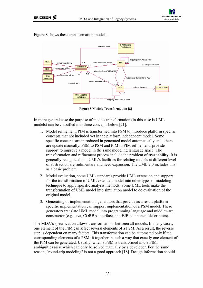
MDA and Integration of Legacy Systems
25
Figure 8 shows these transformation models.
Figure 8 Models Transformation [8]
In more general case the purpose of models transformation (in this case is UML models) can be classified into three concepts below [21]:
1. Model refinement, PIM is transformed into PSM to introduce platform specific concepts that not included yet in the platform independent model. Some specific concepts are introduced in generated model automatically and others are update manually. PSM to PSM and PIM to PIM refinements provide support to improve a model in the same modeling language space. The transformation and refinement process include the problem of traceability. It is generally recognized that UML’s facilities for relating models at different level of abstraction are rudimentary and need expansion. The UML 2.0 includes this as a basic problem.
2. Model evaluation, some UML standards provide UML extension and support for the transformation of UML extended model into other types of modeling technique to apply specific analysis methods. Some UML tools make the transformation of UML model into simulation model to do evaluation of the original model.
3. Generating of implementation, generators that provide as a result platform specific implementation can support implementation of a PSM model. These generators translate UML model into programming language and middleware constructor (e.g. Java, CORBA interface, and EJB component descriptors).
The MDA’s specification allows transformations between all models. In many cases, one element of the PIM can affect several elements of a PSM. As a result, the reverse step is dependent on many factors. This transformation can be automated only if the corresponding elements of a PSM fit together in such a way that exactly one element of the PIM can be generated. Usually, when a PSM is transformed into a PIM, ambiguities arise which can only be solved manually by a developer. For the same reason, "round-trip modeling" is not a good approach [18]. Design information should

MDA and Integration of Legacy Systems
26
always be added at the appropriate level of abstraction. That way, all of the dependent PSMs at the lower levels can be updated automatically to the greatest possible extent. Many industries and research groups propose the MDA tool that support reverse engineering tools, but over this time there is no tool that support fully reverse engineering. The reverse engineering issue and the "mining" process of the PSM to PIM mapping are only described vaguely in the MDA related documents. However, these aspects are of crucial importance for middleware and mediation technologies.
3.3 Developing Applications with MDA
3.3.1 MDA Structure We can think of MDA as a spectrum with business at the top and technology at the bottom where business domain experts work at the top that is in modeling space. Here, UML-based tools provide support and the UML language’s structure and narrower profiles (i.e., tailored subsets) provide guidance. This development step produces PIM model that represents the business functionality and behavior that this MDA application will be executed, as undistorted by technological factors as possible. As we move down to the next abstraction level of the spectrum, the business domain recedes and technology takes over. In traditional UML like UML 1.4 and in a perfectly efficient world, the MDA process might jump directly from the business model at the top of spectrum to the coding or implementation at the bottom, but this is not suitable today since the gap between these level (top to bottom) is too big, let say that discontinuities are too great. The MDA inserts an intermediate step, that acts as bridge between business domain on the top (PIM) to coding/implementation at the bottom. This step produces one or more PSM models. Here, the MDA-enabled tools following OMG-standardized mappings required.
After we completed PSM with the same information set as a coded application, but in the form of a UML model instead of code in a program language and makefiles, we can get the code/implementation with today’s MDA-enabled development tools that automate the conversion of PSM to code very well, although that is not a full code generation. This step is more mature than the PIM-PSM conversion in the previous step. Examples of these tools is Poseidon for Java code.
Using the MDA, application developer concentrates in the business zone at the top. Once the business functionality of the application specified at the high level of abstraction, the generation of code can do with available and automated tools. Drawing from libraries of code assembled by the most skilled programmers available, these tools build scalable, secure, enterprise-quality applications. Cross-platform invocations, hard to program but hardly creative, are coded and maintained by machines, not people.
3.3.2 Build Model Process MDA models must be extremely detailed: The application will be generated from it, and will include only functionality represented explicitly—in the MDA, the business designers and architects play a crucial role [11][12].

MDA and Integration of Legacy Systems
27
The MDA process defines three steps, as depicted in figure 9:
1. First, start with a Platform-Independent Model, in UML and defined at multiple levels. Base level PIM represents only business functionality and behavior, undistorted by technology details. This model must be a detailed model, including stating pre- and post-conditions in OCL and Semantics in Action Language. This detailed model will be map to multiple target platform
2. Next, the PIM is transformed into one or more PSMs. A PSM is tailored to specify system in terms of the implementation constructs that are available in one specific implementation technology or a specific platform, for examples a database model, an EJB model, CORBA, XMI etc.
MDA tool applies an OMG™-standard mapping – formally a UML Profile – that defines the route from an application’s single PIM to PSM on a target platform. PSMs, like the PIM model, will be very detailed. This step may require hand-editing, depending on the tool and environment.
3. The final step is to transform a PSM to implementation or code. Because a PSM fits its technology very closely, this transformation is rather trivial.
A PSM contains the same information as an application, but expressed in UML instead of code. MDA development tools can generate all or most of an application from a PSM: interfaces, templates, configuration files, more. MDA tools will generate application interfaces, code, and other files from each PSM.
Figure 9 Development process of MDA model
A PIM can be mapped to other PIM (refined) n-times until the desired system description level is obtained. Then, the infrastructure is taken into account and the PIM is transformed into a PSM. Then, again, PSMs are refined as many times as needed.
The MDA transformations are executed by tools. Many tools are able to transform a platform specific model to implementation or code automatically. This is where the obvious benefits of MDA lie. It is indeed about time that the burden of IT-workers is eased by automating this part of their job.
Platform Independent
Model
CORBA Model
EJB Model
XML/SOAPModel
Other Models
XML/SOAPCode
CORBA Code
EJB Code
Other Code
PIM
Reverse engineer First transformation
PSM Second transformation
Implementation

MDA and Integration of Legacy Systems
28
3.3.3 Integration of Legacy Systems With MDA concept, any legacy application based on a UML model and a supported middleware platform such as IDL can be included in a company’s circle of MDA interoperability by simply importing its model into MDA context by available tools as platform independent models for new applications are built.
The Model-driven Middleware Maintenance (MMM) process [7] deals with existing legacy distributed heterogeneous systems, which have to be integrated, renovated, redesigned, extended, etc.
Lack of a model is not a barrier; tools on the market today can reverse-engineer UML models from code, and some even work from executables. Alternatively, stand-alone legacy applications can be wrapped with a layer of code that exposes key functionality to the network on a suitable middleware, and the model for this functionality and its interfaces stored in a library for use by MDA developers.
The first activity in the integration of legacy system could be reverse engineering of the existing/implemented code or component information models into the MDA context, PIM or PSM and define the new application system. The reverse engineering steps correspond to PSM to PIM followed by PIM to PIM mappings. Once all component information models are identified and completed, the definition of how they interoperate is needed. This task is similar to the first one and involves the reverse engineering of relationships and dependencies between component information models to be integrated.
The next step is PIM model that have got from the implemented code, again with MDA concept, be integrated with PIM of new application. Before this combined PIM can be transformed to PSM it could be need to get the suitable and ready PIM. This is the mapping PIM to PIM activity.
Finally, from the PSM we can get target code by using of available code generators.
3.3.4 Interoperability An MDA application is not constrained to make all of its remote (and even internal) invocations using the middleware of its PSM. The code generation process is flexible, and the code database of an MDA tool includes invocation formats for every supported middleware platform [11].
Taking advantage of this, developers will pull models of existing applications and services from libraries into the project’s environment as they construct new PIMs, and set up cross-platform invocations by simply drawing the connections in their new model. It’s likely that some of these existing applications will not be on the same platform as the new PSM. Taking its cue from the actual middleware platform of these existing applications, MDA tools will generate cross-platform invocations where needed.
3.3.5 Pervasive Services Every distributed application needs essential services: Naming/directory, transactions, distributed event handling and security are used in virtually every application, but other services come in handy as well. When these services are defined and built on a particular platform, they necessarily take on characteristics that restrict them to that

MDA and Integration of Legacy Systems
29
platform, or ensure that they work best there. To avoid this, OMG will define such services as pervasive services at the PIM level in UML [10][8]. Only after the features and architecture of a pervasive service are fixed, platform-specific definitions will be generated for all of the middleware platforms supported by the MDA.
OMG’s Object Management Architecture contains the industry’s most mature set of standardized services [8]. After it was success constructed and implemented for CORBA, these standard services now define security, transactional and persistence for J2EE thereby proving their multiplatform applicability. OMG will retro-fit these services to the MDA by extracting UML models and generating uniform service definitions for virtually every platform such as web services, .NET, messaging environments and more.
At the abstraction level of a platform-independent business component model, pervasive services are visible only at a very high level (similar to the view the component developer has in CCM or EJB). When the model is mapped to a particular platform, code will be generated (or dynamically invoked) that makes the calls to the native services of those platforms.
In Figure 4 the Pervasive Services such as Transactions, Security, etc., are shown as a ring around the outside of the diagram to emphasize that they’re available to all applications; E-commerce, Healthcare, Telecom, Finance, etc. It is required a common model for directory services, events and signals, and security in integration system.
3.4 The challenge of MDA in real-time Distributed Telecommunication Applications MDA is a general framework that is applicable in different scenarios, and in various vertical domains. The possibility of applicability of MDA in the telecommunication domain have been investigated by EURESCOM [2][3] ranging from Telecommunication Services Access and Subscription (TSAS) modeling of QoS (Quality of Services), application of MDA in telephony networks to Telecommunication Management Network , TMN. In all investigated domains, MDA turned out to be suitable and generally promising because with MDA, development could be done much faster and with less cost at a higher level of quality. However, for some of the selected applications there are additional requirements to MDA. These requirements mainly are the provision and possible standardization of modeling concepts and modeling profiles as well as the standardization of code generation which targets telecommunication specific platforms or APIs like TMN. In particular, modeling concepts for QoS descriptions and modeling profiles for the presentation of models using the concepts have to be defined. The QoS modeling concepts itself are independent from any particular middleware platform, and consequently the resultant models are PIM models. However, since the QoS modeling concepts are used to model non-functional aspects of distributed systems and/or services there must be modeling support for functional aspects as well. Thus, the QoS modeling concepts and modeling concepts for non-functional aspects have to be integrated. After the modeling phase, the QoS models have to be transformed to platform specific code that is used to negotiate, establish and control QoS contracts at runtime. Code generation rules have to be defined in a MDA approach for QoS to automate this transformation.
MDA and Integration of Legacy Systems
30
Their investigation has found that the application of MDA for modeling QoS would imply the following tasks:
- Provision of QoS modeling concepts - Provision of QoS Modeling profiles - Integration with existing concepts/profiles for functional aspects - Provision of code generation rules to address target middleware platforms.
Besides the modeling of QoS-aspects and the provision of code generation rules, it might also be necessary to operate QoS-contract repositories as part of the supporting middleware platform. For this aspect, no adaptations or concretizations to the MDA are required. The existing MOF technology is sufficient to generate and operate such repositories. Such repositories would provide the modeling information about contracts types, requirements and offers at runtime and by that would be the basis for negotiation. After the negotiation phase, a concrete QoS contract, i.e. the agreed contract has to be stored and controlled by the middleware layer. For that purpose, QoS repositories are suitable as well.
As QoS, it is necessary to develop specific sets of modeling concepts and profiles for TMN. After doing so, there should be standardization on these concepts and profiles. To support MDA in the telephony network scenario the current and future services need to be modeled in some modeling language. The modeling language has to include concepts of the used mechanism, Parlay, SIP(Session Initial Protocol) or IN (Intelligent Network). The main issue then would be to address the defined API’s or protocols with specific code generators.
They also concluded that there are no specific requirements to change the MDA to be applied in the TSAS scenario. On one hand, the scenario requires distributed component construction for what the MDA, by definition, suites. There are no telecommunication domain specific modeling concepts necessary that exceed the standard modeling concepts for distributed component platforms. On the other hand, the information model implementation can be done with MDA technologies like MOF and XMI straightforward. More detail can found in [2][3].
3.5 Summary The MDA addresses the challenge of constantly changing infrastructure and promotes application and component reuse and portability.
Since MDA specification proposes solutions to automate the software development process, it depends highly on the availability of MDA tools. These tools should support the creation and transformation of models as well as the code generation for the targeted platforms. The main feature of MDA tools should provided automated model transformation between platform independent model (PIM) and platform specific model (PSM) vice versa. In the following chapter, we discuss the PIM – PSM transformation, reverse engineering as an adoption of MDA specification. We also present our investigation of available MDA tools.

MDA and Integration of Legacy Systems
31
4 PIM – PSM Transformation In MDA, the PIM to PSM and PSM to PIM transformations are important in correspondence with integration of legacy system and new applications. The MDA concept allows one to get a PSM model from implemented code by doing reverse engineering. This PSM can then be transformed into a PIM. In general, model transformations play an important role within the MDA. This includes not only the transformation between PIMs and PSMs but also transformations of data models as supported by the CWM standard [1]. In both cases, the transformation is defined by the provision of rules on the meta-model level. The rules describe how instances of the source meta-model elements are transformed to instances of the target meta-model elements.
4.1 Transformation PIM into PSM In [8] multiple ways to transform a PIM model expressed using UML into a corresponding PSM model expressed in UML are described. The following items are some of them, but there is a note that the list does not address the production of executable code from a platform-specific model.
1. A human could study the platform-independent model and manually construct a platform-specific model, perhaps manually constructing the one-of refinement mapping between the two.
2. A human could study the platform-independent model and utilize models of known refinement patterns to reduce the burden in constructing the PSM and the refinement relation between the two.
3. An algorithm could be applied to the platform-independent model and create a skeleton of the platform-specific model to be manually enhanced by hand, perhaps using some of the same refinement patterns in point 2 above.
4. An algorithm could create a complete platform-specific model from a complete platform-independent model, explicitly or implicitly recording the refinement relation for use by other automated tools.
Fully automated transformations are feasible in certain constrained environments. The degree to which transformations can be automated is considerably enhanced when the following conditions are obtained, as defined in [8]:
1. There is no legacy to take into account 2. The model that serves as input to the transformation is semantically rich 3. The transformation algorithms are of high quality
It is much easier to generate executable code for structural features (attributes, certain associations and similar properties) of a model rather than behavioral features (operations) because the behavior of property getters and setters are quite simple. Automation of transformations is more tractable when the transformation is parameterized, i.e. a human has a pre-defined set of options to select from, to determine how the transformation is performed. For example, a system that transforms a UML model to XML could allow some control over how a UML class’s attributes are transformed, giving a human a chance to choose to put them in an ATTLIST or to put each attribute in a separate ELEMENT.

MDA and Integration of Legacy Systems
32
The PIM to PSM transformation is meant to map the platform independent models to platform specific models. However, as the model definition says, not only structures have to be considered but also function and behavior. At that level, in the past the most often used language for PIMs (UML) have had semantically problems. Behavior specifications in UML were not mapped to code or transformed to PSMs, since they were not precisely, unambiguously defined. One solution for that problem is UML profiling. With profiling the behavior specifications are define in PSM. That means that transformation from PIM to PSM is done by using UML profile. In that case, the profile restricts the semantic of UML and, by doing so, it enables the implementation of model transformation components. Another solution is the evolution towards an action semantics definition for UML and the precise OCL definition [8]. The action semantics specification for UML was recently adopted by the OMG. The objective of the specification is to define what kind of actions can be used to specify the semantics of UML descriptions. The specification provides a metamodel for the actions, defining what kind of different actions exists, how they are related to the existing UML metamodel and what information belongs to an action specification. The OCL is widely used both to define wellformedness rules for the UML meta-model (as well as for other meta-models in the OMG), and as a way for UML users to express precise constraints in UML models. Thus, we can transform precisely from PIM into PSM.
4.1.1 UML Profile Until the beginning of 2003, there is no normative definition of a UML profile, but the Business Object Initiative RFPs elucidated the following working definition of a UML profile. A UML profile is a specification that does one or more of the following [16]:
1. Identifies a subset of the UML meta-model (which may be the entire UML meta-model)
2. Specifies “well-formedness rules” beyond those specified by the identified subset of the UML meta-model. “Well-formedness rule” is a term used in the normative UML meta-model specification to describe a set of constraints written in natural language and OCL that contributes to the definition of a meta-model element
3. Specifies “standard elements” beyond those specified by the identified subset of the UML meta-model. “Standard element” is a term used in the UML meta-model specification to describe a standard instance of a UML stereotype, tagged value, or constraint
4. Specifies semantics, expressed in natural language, beyond those specified by the identified subset of the UML meta-model
5. Specifies common model elements; that is, instances of UML constructs expressed in terms of the profile.
MDA and Integration of Legacy Systems
33
4.1.2 UML Profile for CORBA Most of this section is taken from [16]. The UML Profile for CORBA specification was designed to provide a standard means for expressing the semantics of CORBA IDL using UML notation and thus to support expressing these semantics with UML tools. It is used to represent a CORBA type via UML notation. The usual approach is to model it as a classifier and to stereotype the classifier to indicate whether it represents an interface, or a valuetype, or a struct, or a union, etc. This is a legitimate approach, since a stereotype is one of UML’s official extension mechanisms. Up to now, however, there has been no standard set of extensions of UML for this purpose.
4.1.2.1 Structure of the Profile for CORBA UML profile for CORBA consists of the following:
1. An identified subset of the UML Meta-model, such as association, attribute, binding, etc.
2. Specifications of Standard Elements (Stereotypes, TaggedValues, and Constraints)
3. Specifications of semantics in natural language 4. Specifications of Common Model Elements in terms of the Profile. This Profile
defines a number of CORBA-specific type primitives in the package “CORBA”.
4.1.2.2 Identified Subset of UML The CORBA Profile extends the following standard UML packages: 1) Core, 2) Common Behavior and 3) Model Management. This profile has also concrete meta-classes, and implicitly all super-meta-classes of these metaclasses. From Core: Abstraction, Association, AssociationEnd, Attribute, Binding, Class, Comment, Constraint, DataType, Dependency, ElementOwnership, Generalization, Operation, Parameter, Permission and Usage. From Common Behavior: Exception and from Model Management: ElementImport, Package.
4.2 Reverse Engineering The activity of reverse engineer an implemented application (legacy system) into a UML model is called model transformation; the success of MDA is dependent on it. Three main concepts are involved in model transformation: the source, the destination modeling languages and the mapping between languages. The legacy systems use different software development paradigms and the reverse engineering technique depends on which development paradigm that has been used. It means that reverse engineering in MDA context is differing from procedural or procedural to other paradigms. In this section, we present the difference between conventional reverse engineering of procedural source into another procedural language and reverse engineering of procedural source into MDA context.
4.2.1 Conventional Reverse Engineering Procedural languages structures have many similarities [25]. They have only single entry point into the main program. In addition, they are organized as a set of callable functions and subroutines.

MDA and Integration of Legacy Systems
34
Majority of data managed in these programs are global data. Persistent data is managed through SQL and file IO operations embedded in the source code. Transaction boundaries and error management facilities are hard coded. User interface is often tightly coupled with processing logic. Hence, the design artifacts of procedural systems have often been simple word documents and program source code is the only dependable source of input for reverse engineering automation. A Conventional reverse engineering technique is to gather detailed knowledge about the application and rewrite the business functions in target environment. Figure 10 depicts various stages of the conventional reverse engineering.
Figure 10 Source analysis and recoding [25]
In figure 10, we can observe that the source language programs of an application are parsed and analyzed using a source analyzer. The diagramming facilities in analyzer tools present various views of the application such as program call graph, data usage matrix, algorithm flow chart and so on. These views are primarily read-only and help in gaining business functions implemented in the system and documenting application design in text format. Complete knowledge of the source application is the basis for formulating migration approach. This migration approach normally consists of techniques for mapping data structures, methods for optimizing user interface and guidelines for translating program logic. It would also include activities for business process workflow identification, transaction boundary identification, validation & error conditions, and data table to business entity modeling, data access separation and data schema migration. The application is recoded manually in target language and architecture. Various tools that translate the source code from one language to another have been developed with existing compiler construction tools and language translation technique [25]. These tools use source language’s grammar to parse and recognize input programs. The tool traverses the parse tree and applies language translation rules to generate target language program. A pictorial representation of such a method is given below.

MDA and Integration of Legacy Systems
35
Figure 11 Conventional reverse engineering translator [25]
Reverse engineering of an existing application does not finish with translating source language into target language. It has to be extended into runtime environment migration as well. There is a long distance between source and target environments in architecture, transaction monitor, scripting environment, development tools, tools for performance monitoring and to the level of network and operating system APIs. Mapping platform services from source to target environment has always been a manual task as this is difficult to automate. There are some limitations in the reverse engineering approach described above, such as i) Language translation works on line-by-line conversion concept. It is suited for translation into similar architecture only, ii) Programs produced by language translator are poorly structured, contain cryptic variable names, use non-optimal data structures and maintainability of such programs is difficult, iii) Language translation does not provide design models of the application, iv) Execution effectiveness and artifacts consistency is not repeatable as it depends on development team’s skill set and application knowledge the team possesses, v) Conventional reverse engineering is equivalent to new application development with respect to manual recoding phases and vi) Compliance to component architectures like J2EE is not feasible in language translation approach.
4.2.2 Reverse Engineering in MDA Reverse engineering method of an application in MDA is suggested to be set of model translations [25]. Elements from source program will be extracted and represented as source PSM. UML profile for the source environment will be used in identifying and extracting relevant code segments that match profile elements [16]. Source PSM thus obtained will be subjected to PSM-PIM translation rules to segregate core abstraction thereby platform independent model for the application. Target environment’s UML profile will be applied on this abstract model to arrive at a model that is compliant with target UML profile. This PSM subjected to code generation algorithms yields target language programs. For some PSM elements where abstraction to PIM is not optimal, it is advisable to provide a direct mapping to target PSM through element level mapping rules. Figure 12 illustrates reverse engineering approach as suggested by MDA that contain set of model transformation and translation.

MDA and Integration of Legacy Systems
36
Figure 12 MDA Concept for reverse engineering [25]
4.2.3 Reverse Engineering Tools The activities in reverse engineering could be reverse engineer of implemented code such as CORBA IDL, Java class, C++ or other codes to PSM and could be reverse engineer of PSM to PIM. The reverse engineering activities from implemented code to model (PSM) can be done automatically by most of available UML tools. The following table shows the list of example of UML tools that provide “round trip” engineering with their target code and platform. Table 1 Some UML tools that provide round trip engineering [19]
Company Product Features Platform Adaptive Arts Simply Objects
Professional round-trip engineering for Delphi, Smalltalk, Eiffel, Java, C++, C#, CORBA diagram export, report generator, multi-user
Windows
Borland JBuilder Enterprise class and package diagrams, code navigation, Java reverse engineering, refactoring
Java VM
Gentleware Poseidon for UML adds plug-ins for JavaDoc, reverse-engineering JAR files, Java code synchronization code generation templates
Java VM
Oracle JDeveloper Class and activity diagrams, Java round-trip engineering, XMI export! Windows
Popkin System Architect round-trip engineering for Java, C++, VBA, XML data modeling, Microsoft repository support, scripting, DOORS support
Windows
Rational Rose Professional Adds round-trip engineering, repository support, data modeling; Java, C++, and VB versions sold separately
Windows
WebGain StructureBuilder Enterprise
Round-trip engineering, HTML generation, component of WebGain Studio EJB support, XMI, round-trip engineering of sequence diagrams (unique!)
Java VM
4.3 Research in Models Transformation 4.3.1 Introduction How to transform models into other models is an important key in success of MDA tools. Many techniques are proposed. Since the PSM and PIM are expressed with UML, MOF and CWM, then the transformation process proposed is transformation of these core MDA models to other models. Code is also a model. This means that code generation is also a model transformation. A model is a representation of a systems structure, function and/or behavior at a certain level of abstraction. During model transformation in the sense of a PIM to PSM

MDA and Integration of Legacy Systems
37
mapping, the information contained in a PIM has to be transformed to a representation in a PSM, which is equivalent to that contained in the PIM. Some of PIM-PSM transformation is not difficult especially when it only concerns structural aspect while others transformation can be quite difficult for certain PSM. For example, when transforming PIM into Java, it could be difficult since there are some PIM features that are not supported by Java. Java does not support multiple inheritances and some association types.
4.3.2 Existing Approaches G., Anna, et al in [22] have identified that some approach to the models transformation has been proposed. The existing approaches to implementing transformations are the following:
4.3.2.1 CWM Transformation A key aspect of data warehousing is to extract, transform, and load data from operational resources to a data warehouse or data mart for analysis. Extraction, transformation, and loading can all be characterized as transformations. In fact, whenever data needs to be converted from one form to another in data warehousing, whether for storage, retrieval, or presentation purposes, the application of transformation rules is involved. Transformation, therefore, is central to data warehousing. Also in chapter 13 of the OMG’s Common Warehouse Metamodel Specification [20] found about a model for describing Transformations. It supports the concepts of both black-box and white-box transformations. Black-box transformations are not of much interest to us because they only associate source and target elements without describing how one is obtained from the other. White-box transformations, however, describe fine-grained links between source and target elements via the Transformation element’s association to a ProcedureExpression. Unfortunately, because it is a generic model and re-uses concepts from UML, a ProcedureExpression can be expressed in any language capable of taking the source element and producing the target element. Thus CWM offers no actual mechanism for implementing transformations, merely a model for describing the existence of a mapping.
4.3.2.2 Graph Transformation There are many articles on model transformation based on Graph Transformations. In [23], a transformation consists of a set of rules combined using a number of operators such as sequence, transitive closure, and repeated application. Each rule identifies before and after sub-graphs, where each sub-graph may refer to source and target model elements and associations between them (introduced by the transformation). This style of approach to model transformation introduces non-determinism in the rule selection, and in the sub-graph selection when applying a rule. In addition, since rules are applied in a sequence, thus resulting in a series of state changes, one needs to be very careful about repeated rule application to ensure termination, and the order of rule application. More details description of graph transformation can be found in [23]
MDA and Integration of Legacy Systems
38
4.3.2.3 Use of UML Profiles UML Profiles have an important role to play in model mapping. Transcription rules can be done inside UML tools or by external tools. A model can be expressed in a given formalism, then to transform the model into another model leads to compare the formalism they are based upon, i.e., to compare their primitives and their semantics. Consequently, model mapping is a meta-modeling activity.
The profile description includes the specification of Stereotypes and Tagged Values and the UML meta-classes associated with these extensions [16]. The profiles are supported and handled with modules. A module can include commands applied to model elements. These commands implement the transformation of models.
4.3.2.4 Generated XSLT eXtensible Stylesheet Language for Transformation (XSLT). A transformation in the XSLT language is expressed as a well-formed XML document conforming to the namespaces in XML Recommendation [40], which may include both elements that are defined by XSLT and elements that are not defined by XSLT. XSLT-defined elements are distinguished by belonging to a specific XML namespace, which is referred to in this specification as the XSLT namespace. Thus, this specification is a definition of the syntax and semantics of the XSLT namespace.
A transformation expressed in XSLT describes rules for transforming a source tree into a result tree. The transformation is achieved by associating patterns with templates. A pattern is matched against elements in the source tree. A template is instantiated to create part of the result tree. The result tree is separate from the source tree. The structure of the result tree can be completely different from the structure of the source tree. In constructing the result tree, elements from the source tree can be filtered and reordered, and arbitrary structure can be added.
A transformation expressed in XSLT is called a stylesheet. This is because, in the case when XSLT is transforming into the XSL formatting vocabulary, the transformation functions as a stylesheet. It contains a set of template rules. A template rule has two parts: a pattern that is matched against nodes in the source tree and a template which can be instantiated to form part of the result tree. This allows a stylesheet to be applicable to a wide class of documents that have similar source tree structures.
A template is instantiated for a particular source element to create part of the result tree. A template can contain elements that specify literal result element structure. A template can also contain elements from the XSLT namespace that are instructions for creating result tree fragments. When a template is instantiated, each instruction is executed and replaced by the result tree fragment that it creates. Instructions can select and process descendant source elements. Processing a descendant element creates a result tree fragment by finding the applicable template rule and instantiating its template. Note that elements are only processed when they have been selected by the execution of an instruction. The result tree is constructed by finding the template rule for the root node and instantiating its template.
In the process of finding the applicable template rule, more than one template rule may have a pattern that matches a given element. However, only one template rule will be applied. A single template by itself has considerable power: it can create structures of arbitrary complexity; it can pull string values out of arbitrary locations in the source

MDA and Integration of Legacy Systems
39
tree; it can generate structures that are repeated according to the occurrence of elements in the source tree. For simple transformations where the structure of the result tree is independent of the structure of the source tree, a stylesheet can often consist of only a single template, which functions as a template for the complete result tree.
When a template is instantiated, it is always instantiated with respect to a current node and a current node list. The current node is always a member of the current node list. Many operations in XSLT are relative to the current node. Only a few instructions change the current node list or the current node during the instantiation of one of these instructions, the current node list changes to a new list of nodes and each member of this new list becomes the current node in turn; after the instantiation of the instruction is complete, the current node and current node list revert to what they were before the instruction was instantiated.
4.3.2.5 Text-based Tools Text based tools such as awk and perl are suitable only for the simplest kinds of transformations, largely because they deal with concrete syntax rather than abstract syntax. While arguably more readable and maintainable than XSLT transformations, they require the parsing of input text and serialisation of output text, rather than providing the abstraction of a parse-tree as XSLT does.
4.3.2.6 Script Language Some UML tools include imperative script languages with meta-model navigation facilities similar to OCL navigation expressions. These languages are the support to implement the mapping scripts. These languages are flexible but often are tool dependent, and a mapping implementation is not portable [21]
4.3.2.7 Generating & importing XMI. Some tools provide support to process and generate XML and XMI files. These files include the meta-data of UML models and mapping is supported by transformation of XMI files. The mapping is independent of the UML tool. Examples of the tools that support this technique are Rational Rose, Poseidon, and objecteering.
4.3.2.8 MOF Transformation Some tools include MOF transformation facilities based on rules. These rules provide facilities to identify the elements in the source model, where we apply the rule and the destination elements that we generate with the rules. An examples of the tool that support this technique is Rational Rose.
4.4 Available MDA Tools The MDA process is implemented by tools that integrate modeling and development into a single environment that carries an application from the PIM, through the PSM, and then via code generation to a set of language and configuration files implementing interfaces, bridges to services and facilities, and possibly even business functionality.
Several vendors already provide tools that support integration at about this level, including substantial code generation. Although these tools were not built explicitly to OMG's MDA standard (which was not complete when they were created), it is pleasing to see this level of support for MDA so early in its development. Many other vendors

MDA and Integration of Legacy Systems
40
are currently hard at work on MDA-based development tools, so It can be expected to find advance MDA tools in the future which explicitly compliant OMG's standard. The generation of application code from an MDA PIM through an automated or semi-automated series of steps will be the biggest benefit of MDA. Generally, applicable MDA tools will initially move beyond modeling with the generation of code for
1. interfaces (in OMG IDL and other interface-defining languages) 2. functionality constrained by a specification (such as the CORBA Component
Model, or EJB) 3. access to MDA-standardized Pervasive Services and Domain Facilities 4. cross-platform access to functionality already standardized in the MDA, via an
automatically-generated bridge 5. wrappers for hand-coded execution engines that make access transactional or
secure, as long as the basic interfaces to these engines have been defined in the MDA
6. operations that get and set the values of variables declared in the model. The next versions of tools will code execution of simple business rules; future versions will become even more sophisticated. We have studied some of the available MDA tools as presented below.
4.4.1 Telelogic Tau This tool includes three important parts that are Tau/Architect, Tau/Developer and Tau/Tester [32]. Telelogic Tau supports UML modeling, action language to specify dynamic aspects of system’s behavior, which is compatible with UML action semantic and complete application generation (C and extended C++ code) from all diagrams. The tool also supports model verification with controllable model simulation that give engineers possibility to verify their work in the analysis, design, and implementation phases. As a result, they can quickly locate and remove errors early when corrections can be made easiest and most cost effectively. An additional feature is generating of documentation for a project. For more information about the tool, visit Telelogic website [32].
4.4.2 ArcStyler ArcStyler provides a comprehensive, architecture-driven solution for end-to-end model-driven application development. By assisting developers with important architectural tasks, the ArcStyler simplifies and expedites the entire development life cycle, from the platform-independent business model to platform-specific refinement and optimized partial code generation for the leading J2EE, CORBA, .NET, EAI and legacy platforms, in line with the Unified Process and with the concepts of MDA [33]. ArcStyler includes support for the development of component-based architectures implemented on EJB platforms. Business and platform independent concepts are expressed on business models. Business modeling comprises the first stage in the full cycle development of component-based software systems. These models are transformed automatically into component models, which are EJB specific models. Business models are expressed in a proprietary modeling language, and component
MDA and Integration of Legacy Systems
41
models are based on a UML profile. ArcStyler provides support for the automatic generation of EJB components, from component models. ArcStyler supports customization of the transformation process. Customization is based on the cartridge configuration files and templates. JPython is used as the transformation language, some scripts are generated automatically, and others are specific to the generation process. Others features offered by this tool are test & simulation, export import model with standard XMI / XML. Additional information about this tool can be found at ArcStyler’s website [33].
4.4.3 Objecteering Besides providing a UML modeler, Objecteering also provides support for description of UML profiles (Profile Builder) [34]. The profile description includes the specification of Stereotypes and Tagged Values and the UML meta-classes associated with these extensions. The profiles are supported and handled with modules. A module can include commands applied to model elements. These commands implement the transformation of models. They are scripts in a proprietary language (J language). J provides support for the creation of new diagrams and model elements. The commands support transformations from model to model or from model to code or documents. Objecteering provides traceability support to avoid inconsistency between the model source and the model or code destination. Other features coming with this tool are complete code generating for Java up to 70 % & support Java pattern, code generating for C++ up to 70%, and exchange model via standard XMI, test for EJB, creation, definition, execution and documentation. For further information about the tool, visit Objecteering’s webaite [34].
4.4.4 Poseidon Poseidon offers basic features such as UML modeling, support for XMI as standard saving format, support of OCL, partial code generation for Java, reverse engineering from Java source [35]. For the needs of software developers, Poseidon has also capability to integrate with most popular plug-ins to support roundtrip UML/Java, UML documentation, generating Java code from state chart, and generating Java code from OCL. Additionally, Poseidon allows importing Rational Rose ".mdl"-files. Code generation in Poseidon for UML is based on the Velocity Template Language. Velocity is an open source template engine developed as part of the Apache/Jakarta project. Originally designed for use in the development servlet based Web applications, it has also proved useful in other areas of application including code generation, text formatting and transformation. The standard templates supplied with Poseidon for UML can be used to generate Java code based on class diagrams. The generated Java code is fully Java 2 compliant. The code can make use of all the features supported by Java 2, including exception handling, inner classes and static initializers. With the Developer Edition, we can modify the supplied templates or create templates to generate other output formats such as IDL files or C++ code. A complete documentation and information about this tool can be found at Poseidon’s website [35].
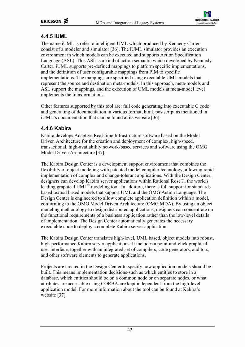
MDA and Integration of Legacy Systems
42
4.4.5 iUML The name iUML is refer to intelligent UML which produced by Kennedy Carter consist of a modeler and simulator [36]. The iUML simulator provides an execution environment in which models can be executed and supports Action Specification Language (ASL). This ASL is a kind of action semantic which developed by Kennedy Carter. iUML supports pre-defined mappings to platform specific implementations, and the definition of user configurable mappings from PIM to specific implementations. The mappings are specified using executable UML models that represent the source and destination meta-models. In this approach, meta-models and ASL support the mappings, and the execution of UML models at meta-model level implements the transformations. Other features supported by this tool are: full code generating into executable C code and generating of documentation in various format, html, postscript as mentioned in iUML’s documentation that can be found at its website [36].
4.4.6 Kabira Kabira develops Adaptive Real-time Infrastructure software based on the Model Driven Architecture for the creation and deployment of complex, high-speed, transactional, high-availability network-based services and software using the OMG Model Driven Architecture [37]. The Kabira Design Center is a development support environment that combines the flexibility of object modeling with patented model compiler technology, allowing rapid implementation of complex and change-tolerant applications. With the Design Center, designers can develop Kabira server applications within Rational Rose®, the world's leading graphical UML® modeling tool. In addition, there is full support for standards based textual based models that support UML and the OMG Action Language. The Design Center is engineered to allow complete application definition within a model, conforming to the OMG Model Driven Architecture (OMG MDA). By using an object modeling methodology to design distributed applications, designers can concentrate on the functional requirements of a business application rather than the low-level details of implementation. The Design Center automatically generates the necessary executable code to deploy a complete Kabira server application.
The Kabira Design Center translates high-level, UML based, object models into robust, high-performance Kabira server applications. It includes a point-and-click graphical user interface, together with an integrated set of compilers, code generators, auditors, and other software elements to generate applications.
Projects are created in the Design Center to specify how application models should be built. This means implementation decisions-such as which entities to store in a database, which entities should be on a common node or on separate nodes, or what attributes are accessible using CORBA-are kept independent from the high-level application model. For more information about the tool can be found at Kabira’s website [37].

MDA and Integration of Legacy Systems
43
4.4.7 UMT UML Model Transformation Tool (UMT) is a tool to support model transformation and code generation based on UML models in the form of XMI [38]. XMI models are imported and converted by the tool into an intermediate format that is the basis for validation and generation towards different target platforms. The intermediate format is an XML format, which is called XMI-Light. See the following figure.
Figure 13 UMT tool
From figure 13 above, we can see basic mechanism in UMT tool. As input, UML model is imported from other UML modeler such as Rational Rose, Together, Poseidon etc, via XMI format. The XMI file then transformed into intermediate XMI format called XMI-Light by XSLT. This PIM model then can be transformed into various target code such as EJB, Java interface, WSDL, SQL, GML, IDL, INESC workflow or XML schema. For more information and complete documentation about this tool can be found at UMT’s website [38].
4.5 Visions for the Future MDA tools MDA tools are just evolving and the existing tools, depending on their history, are beginning to support a few or many features of an MDA tool [28]. Beyond the basic capabilities of current MDA tools, the following paragraphs outline some visions for the future direction of such tools. Because meta-data will become more important and the feature-list will continue to grow, it seems inevitable that MDA platforms will evolve to integrate different partial tools (called plug-ins) from different vendors. Besides, the necessary common meta-data repository of such platforms, the dynamic collaboration of the user interfaces of the different tools, as part of the platform is an important direction for future tools. MDA tool is most likely to be a repository of meta-data based on either the UML meta-model or the MOF meta-meta-model or at least compatible with one or both. To interact with various tools or tool components it has to be an active repository - propagating changes to all interested applications through events. It has to be possible to fill the repository with meta-data from all kinds of sources and to export all the data in proper formats, with XMI the standard format for model-interchange. Beyond collaboration of different vendors in a platform, new visualization capabilities will be integrated into future MDA tools to allow more domain specific work with meta-models and models. These capabilities could attract domain experts looking for easy ways to change and extend their applications without diving deep into programming.
UML Model
XMI doc of UML Model
XSL Translator 1
XMI Light of UML Model
XSL Translator 2
Java, C#,... XML, GML, WSDL
DB SQL EJB, Net, J2EE
UMT

MDA and Integration of Legacy Systems
44
Eventually MDA tools will split their personality into analyst views, designer views, developer views, administrator views and even end-user views. It is the ultimate goal of MDA the avoidance of code wherever possible. Another area of improvement is the support of aspect-oriented modeling, more (graphical) control over model transformations based on new OMG standards and the modeling of variants. With more precise semantic modeling, i.e. UML action semantics and new versions of behavioral diagrams in UML 2.0 to allow MDA tools an advanced simulation of the specified models [28]. Before any code has to be deployed, the model semantic can be tested against specific cases with end-user observation and intervention. The platform approach would help again to integrate already existing simulation engines into the MDA platform. The need for analysts and developers is more complete and sophisticated verification of models to prevent mistakes. To measure the progress of an MDA project, advanced metrics need to be supported inside the MDA platform. The software development process paradigms, like RUP need to be tailored for MDA projects and support for the processes could be integrated into MDA tools or platforms. As test and deployment is an integral part of these process models the MDA platforms need defined ways of doing integrated and automated testing and a the full support of deployment in the targeted domains. MDA is also about integration of existing (legacy) applications. Although import of meta-data from existing applications is already covered by most MDA tools (XMI, CWM, Harvesting of Code), the needs of a tool to allow the development of MDA verticals will go beyond the import and transformation of meta-data. Each vertical flavor of an MDA tool contains concrete technology bridges and adapters to simulate and test not only on the platform independent modeling level but also against existing platforms. The goal of a vertical oriented MDA environment is the support of the domain experts in designing, testing and simulating solutions for a particular domain. In most cases, MDA tools will generate code for standardized platforms, like J2EE or .NET. However, often the platforms miss important pieces or do not go far enough in their automation efforts. In such cases, it seems appropriate to extend MDA tools by runtime components that allow domain-experts to change important aspects of their system (their meta-data) during runtime or after deployment. Because these components are dependent or derived from the meta-models, it is necessary to see them as an integral part of the MDA tool to allow consistent forward-engineered changes. Based on our study about MDA tools and overview described above, we can conclude the need for perfect MDA tool, which have to support the following features: − UML modeling support Action Language and/or OCL − Support model documentation and web publishing. − Code generators for major platforms − XMI model interchange − Integrated IDE − Integration of modules at the PIM level, re-use previously-built PIM modules − Transformation PIM into various PSM − Integration with EIA tools

MDA and Integration of Legacy Systems
45
− CIM/PIM/PSM differentiation available − Reverse engineering and round-trip engineering − Executable models (in run-time as well as in development) − Metamodel approach, so new UML and other metamodels can be developed and
“plugged in” − Conform with MDA specification and pluggable PIM architecture − Support for GUI and Data specification consistent with architecture − Pluggable generators and mappings if necessary − Pluggable “glue” code consistent with architectures supported − Tool designed using MDA for fast evolution − Scalable to large development teams − Repository support, versioning, sharing, revision-marking, etc. − Excellent user interaction design 4.6 Summary MDA requires model transformation to succeed. Two main concepts are involved in model transformation: the source and destination modeling languages and the mapping between languages. UML transformations are used for three general purposes; model refinement, model evaluation and generating of implementation. Although promising MDA tools are appearing at the beginning of 2003, in the perception of the mainstream developer, there is little in terms of concrete tools that actually support MDA beyond traditional UML modeling and skeleton-class generation. Evolving older tools provide features to define and instantiate design patterns, but most of these tools still expose the user to UML models at the level of abstraction of implementation code. Some traditional UML tools, like Rational Rose, provide reengineering of programming languages such as CORBA IDL, Visual Basic, Java, etc., but we have not found a tool that provides automatic transformation from PSM to PIM in the higher level of abstraction. In the next chapter, our case study, we tried to develop a PIM from the existing UML model, IDL interfaces and implemented code. In the MDA context, this step is an important step in connection with the integration of legacy systems.

MDA and Integration of Legacy Systems
46
5 Case Study In this chapter, we present our case study that consists of three parts. We begin with study about which aspects of the context system (a real-time distributed telecommunication application) can be specified in a PIM and which aspects are left for PSM and coding. The next study is about using XMI as a standard of model exchange. Finally, we demonstrated how to develop PIM from the existing UML models, IDL CORBA and Erlang codes.
5.1 Models for Case Study Models we used in our case study are part of the Ericsson’s GPRS (General Packet Radio Services) project. Figure 14 shows an overview of the GPRS system. Software systems that have been developed in Ericsson Grimstad is software to handle SGSN and GGSN system as depicted in grey rectangle in the middle of the figure.
Figure 14 GPRS System [31]
A GPRS Support Node (GSN) contains functionality that is required to support GPRS functionality for GSM (Global System for Mobile communication) and/or UMTS (Universal Mobile Telecommunications System). The SGSN & GGSN nodes constitute the Ericsson GSN system. From documentation of GSN system, we found description of SGSN and GGSN node as mentioned below: − The Serving GPRS Support Node (SGSN) keeps track of the individual MS’s
location and performs security functions and access control. The SGSN is connected to the GSM base station system through the Gb interface and/or to the UMTS Radio Access Network through the Iu interface. The SGSN also interfaces the GSM Service Control Function (SCF) for optional CAMEL2 session and cost control service support (carried out via the GPRS Service Switching Function, SSF).
− The Gateway GPRS Support Node (GGSN) provides inter-working with external packet-switched networks (PDN) via the Gi interface. GGSN is connected with SGSNs via an IP-based packet domain PLMN backbone network, the Gn interface.
2 CAMEL (Customized Applications for Mobile Networks Enhanced Logic) offers Intelligent Network services in GSM/UMTS, whereas prepaid subscribers is one.
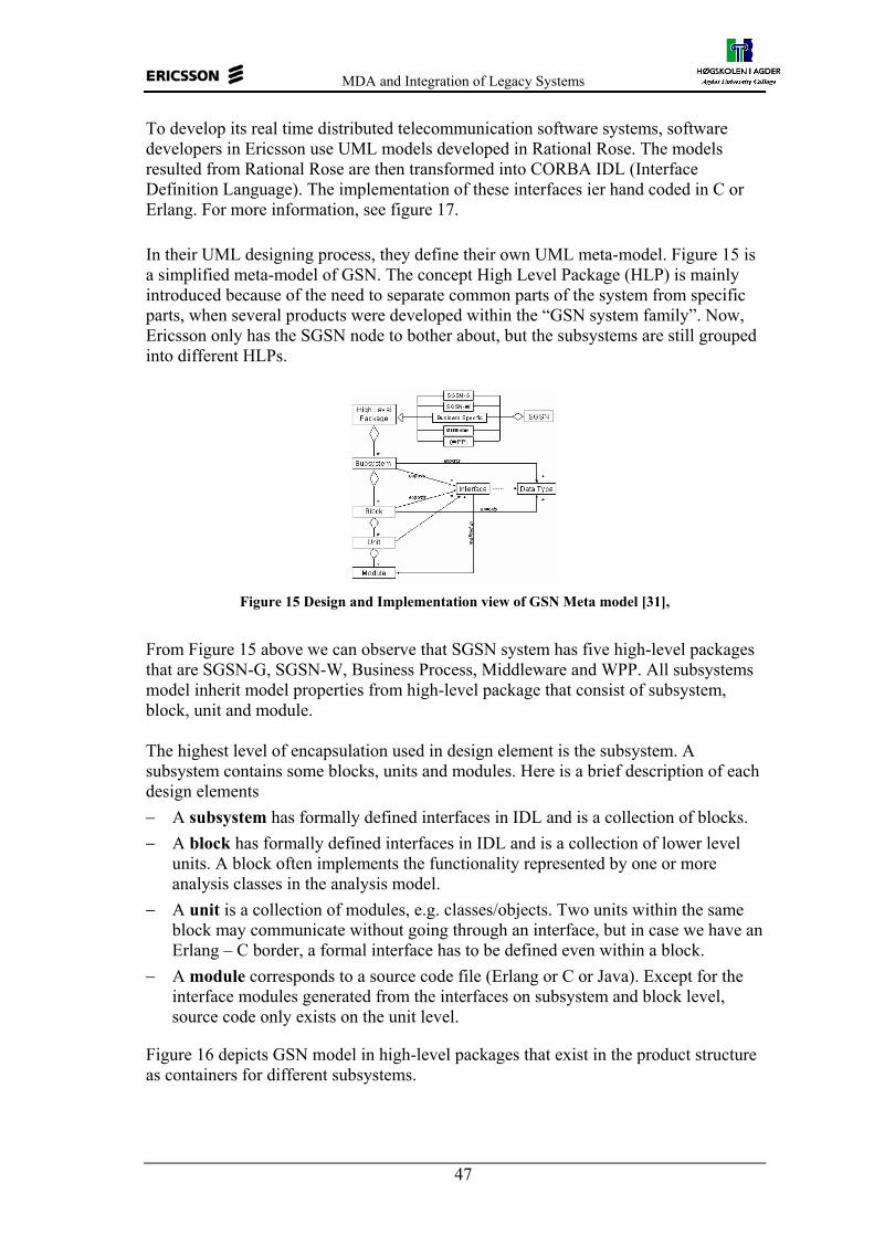
MDA and Integration of Legacy Systems
47
To develop its real time distributed telecommunication software systems, software developers in Ericsson use UML models developed in Rational Rose. The models resulted from Rational Rose are then transformed into CORBA IDL (Interface Definition Language). The implementation of these interfaces ier hand coded in C or Erlang. For more information, see figure 17. In their UML designing process, they define their own UML meta-model. Figure 15 is a simplified meta-model of GSN. The concept High Level Package (HLP) is mainly introduced because of the need to separate common parts of the system from specific parts, when several products were developed within the “GSN system family”. Now, Ericsson only has the SGSN node to bother about, but the subsystems are still grouped into different HLPs.
Figure 15 Design and Implementation view of GSN Meta model [31],
From Figure 15 above we can observe that SGSN system has five high-level packages that are SGSN-G, SGSN-W, Business Process, Middleware and WPP. All subsystems model inherit model properties from high-level package that consist of subsystem, block, unit and module. The highest level of encapsulation used in design element is the subsystem. A subsystem contains some blocks, units and modules. Here is a brief description of each design elements − A subsystem has formally defined interfaces in IDL and is a collection of blocks. − A block has formally defined interfaces in IDL and is a collection of lower level
units. A block often implements the functionality represented by one or more analysis classes in the analysis model.
− A unit is a collection of modules, e.g. classes/objects. Two units within the same block may communicate without going through an interface, but in case we have an Erlang – C border, a formal interface has to be defined even within a block.
− A module corresponds to a source code file (Erlang or C or Java). Except for the interface modules generated from the interfaces on subsystem and block level, source code only exists on the unit level.
Figure 16 depicts GSN model in high-level packages that exist in the product structure as containers for different subsystems.

MDA and Integration of Legacy Systems
48
Figure 16 High level package of GSN model [31].
Use case view defines the functional requirements for GSN expressed as use cases. Non-functional requirements are captured in supplementary specifications that can be reached via requisite database.
Logical view consists of one package that defines system architecture and a number of product related package that encapsulates the design for different parts in the GSN product. SGSN-GT contains modeling of SGSN for GSM/TDMA.
Business specific package contains the business specific parts of the GSN system which are common for the packet services within the GSM/UMTS domain and may be used by all specific applications defined within GSN. The Business Specific package collects components that implement functionality common to both SGSN-G and SGSN-W, the idea is to share common functionality between the two SGSN variants. The Business Specific might take advantage of functionality provided by Middleware and WPP.
The purpose of System Architecture package is to have common system architecture ideas that control the development and evolution of the nodes, SGSN and GGSN. The responsibility of this package is to form system architecture for Ericsson GSN products, SGSN and GGSN. That means to consider the necessary aspects/viewpoints of the system and the structures they impose, its components and their inter-relationships as well as the strategies/concepts that governing the design and evolution of the system. The major aspects that are addresses are logical architectural aspect, physical architectural aspect, deployment architectural aspect, concurrency aspect, dynamical behavioral aspect and software aspect.
Package SGSN-W contains modelling of SGSN for W-CDMA. This SGSN-W package collects components that implement SGSN-W specific functionality; it might take advantage of functionality provided by the Middleware, Business Specific and WPP packages in order to fulfil its tasks.
The Middleware package collects components that implement the application framework. The SGSN-G package collects components that implement SGSN-G specific functionality; it might take advantage of functionality provided by the Middleware, Business Specific and WPP packages in order to fulfill its tasks.
The WPP package collects components that implement the wireless packet platform. The purpose of WPP package is to group logic that is generic for several types of nodes, e.g. GSN, into a unit that is distributable to an Ericsson organizational unit and possible to develop and implement by its own "without" knowledge of its clients/user.

MDA and Integration of Legacy Systems
49
Responsibility of this package to offer necessary classes/ abstractions, etc. of WPP related parts, which shall/can be used in diagrams in other packages when modeling more GSN-specific parts.
As we have mentioned earlier, software developers in Ericsson use UML model as modeling concept at early stage of their software development. Then the models are transformed into IDL. Finally, these interfaces are implemented manually in C or Erlang code. Erlang is a procedural programming language that has been using Ericsson to develop their application. Figure 17 shows this design concept.
A&D focus
SourceCode
(Erlang / C )
ExecAnalysisClasses
DesignElements
[SubSystem/Block/Unit/(Module)]
IDLCode
SupplementarySpecifications
Use-Case Model
Domain Object Model
Use CaseSpecifications
Figure 17 Analysis and Development used by Ericsson [31]
From Figure 17 above we can see that from requirement to executable, Ericsson use IDL code to specify the component. In implementation, one IDL interface may be realized by many files. It is also found that many procedures in Erlang file can not be found in IDL interface, although they defines as public with -export declaration (used by other modules in other unit, block or subsystem). It happens because change of the source code is not followed by change of the IDL or models.
Our case study was to develop PIM from the existing UML models, interfaces specified in IDL CORBA and Erlang codes. Since the GSN model is too big and the fact that the term of PIM is relative thing and there are many levels of PIM, we only used one subsystem from SGSN-GT systems and one subsystem from Middleware in our case study. These two subsystems are implemented in Erlang. We discuss more how to develop the PIM from the whole GSN system in discussion in chapter 6.
5.2 Goals, Method and Tools Used The main focus of our case study is the possibility of developing a PIM from existing UML, interfaces IDL and other artifacts (in this case Erlang Codes). To facilitate this study, we got access to documentation of GPRS files project which developed by Ericsson. From this documentation, we got UML models, IDL CORBA and Erlang code files which we needed in our case study. The first, and as a pre study, we tried transforming of the UML models into XMI format to provide support for using various tools as defined in MDA specification. The aim of this case study is to investigate and prove that XMI can be used to exchange the UML models between tools. At the first step of this case study, we made a UML model in Rose and exported into XMI file using XMI plug-in for Rose. Then, we tried to import this XMI file by various MDA tool that support model exchange such as Poseidon, UMT, Objecteering and so on. We investigated the compatibility of XMI.

MDA and Integration of Legacy Systems
50
To develop PIM UML model we used the following methods. 1. We began with the using of a single Erlang module to make a corresponding
UML class/or interface. 2. After all Erlang modules are translated into UML classes, then we search how
the classes interoperate, by means of dependencies, associations etc. 3. In addition, to have more complete UML class, such as datatypes, we used the
information from the IDL files. These three steps generate a UML model that is a specificationally complete PIM It means that from Erlang code and IDL, we take out structural aspect. All the UML classes are presented in the XMI format. We would also use part of the existing UML (external behavior aspects such as use case diagram, activity diagram, etc.) to get more complete PIM. This part of existing UML model should also be translated into XMI the format. Up to this step, we have two parts of UML model in XMI that are XMI generated by translation of Erlang (structural aspects), and XMI generated by translation of existing UML (behavior aspects) with Rational Rose. For more detail, see figure 18.
Figure 18 PIM Development Method
To combine the two XMIs we need a XMI mixer that should generate PIM in XMI format as a result. As shown in figure 18 that from the translator that we developed, we can get a structural specificationally complete PIM (A), while from the XMI mixer we can get a structural and behavior specificationally complete PIM (B). In this thesis we only made the translator and the XMI mixer parts. This means that the PIM we would try to build is only a structural specificationally complete PIM, but we discuss the possibility of developing a structural and behavioral specificationally complete PIM in chapter 6. As tools, we used JBuilder 5 with Java 1.3, Rational Rose software and UMT. The Jbuilder was used to make the Translator and XMI mixer. The Rose2000 was used to transform/export the existing UML model into XMI and to import the XMI we had from our translator. This step was to check that the translator works perfectly. UMT, Poseidon, Objecteering, ArcStyler and Rational Rose used to prove the using of XMI to model exchange between tools.
A B
CORBA IDL
Existing UML
Erlang Code
XMI MixerXMI (PSM)
Translator-1XMI (PIM)
PIM generator
A: structural specificationally complete PIM B: structural and behavioral specificationally complete PIM
Rose

MDA and Integration of Legacy Systems
51
5.3 Considered Aspects of Developing a PIM The term “legacy system” in this case refers to the part of the GPRS application written in Erlang
As we have mentioned earlier there are some issues that distinct PSM from PIM. PSM contains platform specific information that cannot be part of platform independent model. Examples of these platform specific aspects are communication mechanism, message type, transaction handling, event handling, exception handling, database access mechanism, database type, operation sequence, security handling and so on. These aspects usually are part of a platform specific profile. This profile defines how a platform specific model should be structured for a specific platform. Ideally, platform specific model should be generated by modeling tool. In practice, it will most often be partially generated and refined by the user.
UML model has two main aspects that are structural and behavioral. Structural aspects can be a form of model packaging, class diagram, class, attribute, operation, stereotype, datatype etc. Behavioral aspects consist of external part such as state machine, use case diagram, activity diagram, dependency and internal part such as action language. Action language is presentation of computational features.
In the next two sections, we present an analysis --based on features described above-- of implementation code of Ericsson’s telecommunication system that is implemented in Erlang. Since many applications are implemented in Erlang code and the fact that all the information (structural and behavioral aspects) exist in code, we only analyzed Erlang code to determine which aspect can be specified in UML model (PIM) and which aspects have to be left in code or PSM.
5.3.1 Aspects Specified in PIM As we have written in section 3.2.1, a specificationally complete PIM is defined as a complete model of the system specification – the external structure and behavior – of a component system in terms of a business model, a requirements model and an architecture model. In short, we can say that a PIM should consist of structural and behavioral aspects so when we want to develop a complete PIM from legacy system (source code), we have to involve these aspects both of internal and external in the resulted PIM.
We have developed a translator that can transform Erlang code into UML model in XMI format that is a PIM. This translator is developed in Java. We called this translator as Erlang to XMI Translator. See section 5.5.1.6 for more detail.
Implemented Erlang source code contains information about both of structural and behavioral (internal and external) features. Beside that, it also contains other information that is platform specific. Some of these features can be taken into a UML model and are platform independent such as model packaging, class, attribute, operation, operation’s argument, datatype, stereotype and dependencies, while other aspects are platform specific. More about platform specific aspects are discussed in section 5.3.2.
Another parts that must be specified in PIM is internal behavior (computationally) that exist in detail sources code such as code for each operation, case-of statement, etc. In UML model, this part is usually expressed as action semantic language.
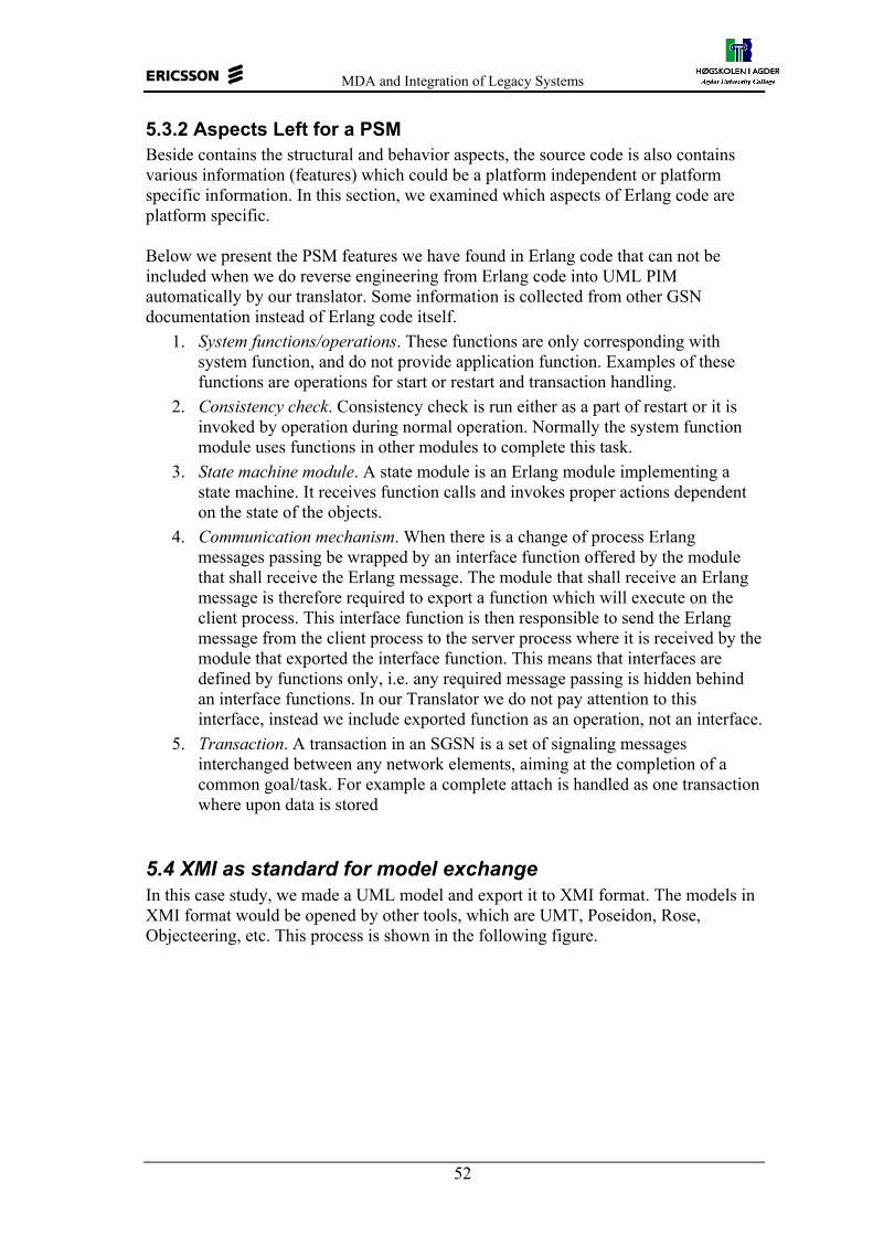
MDA and Integration of Legacy Systems
52
5.3.2 Aspects Left for a PSM Beside contains the structural and behavior aspects, the source code is also contains various information (features) which could be a platform independent or platform specific information. In this section, we examined which aspects of Erlang code are platform specific. Below we present the PSM features we have found in Erlang code that can not be included when we do reverse engineering from Erlang code into UML PIM automatically by our translator. Some information is collected from other GSN documentation instead of Erlang code itself.
1. System functions/operations. These functions are only corresponding with system function, and do not provide application function. Examples of these functions are operations for start or restart and transaction handling.
2. Consistency check. Consistency check is run either as a part of restart or it is invoked by operation during normal operation. Normally the system function module uses functions in other modules to complete this task.
3. State machine module. A state module is an Erlang module implementing a state machine. It receives function calls and invokes proper actions dependent on the state of the objects.
4. Communication mechanism. When there is a change of process Erlang messages passing be wrapped by an interface function offered by the module that shall receive the Erlang message. The module that shall receive an Erlang message is therefore required to export a function which will execute on the client process. This interface function is then responsible to send the Erlang message from the client process to the server process where it is received by the module that exported the interface function. This means that interfaces are defined by functions only, i.e. any required message passing is hidden behind an interface functions. In our Translator we do not pay attention to this interface, instead we include exported function as an operation, not an interface.
5. Transaction. A transaction in an SGSN is a set of signaling messages interchanged between any network elements, aiming at the completion of a common goal/task. For example a complete attach is handled as one transaction where upon data is stored
5.4 XMI as standard for model exchange In this case study, we made a UML model and export it to XMI format. The models in XMI format would be opened by other tools, which are UMT, Poseidon, Rose, Objecteering, etc. This process is shown in the following figure.

MDA and Integration of Legacy Systems
53
Figure 19 XMI for model exchange between tools
Not all tools support export/import of XMI. For example the Telelogic Tau does not support this facility. An important aspect of this process is the XMI version. Various UML tools in the market use different version of XMI. In our investigation of UML tools, Poseidon and Rose can export-import XMI file, see table 2 for more detail. Although UMT supports import of XMI files, but only XMI files that are of the same version (UMT use the XMI 1.0 for UML 1.3) can opened by UMT. UMT could open XMI files exported by Poseidon, Objecteering and Rose. Here is an example of the model made by Poseidon.
Figure 20 UML model made by Poseidon
This model then is transformed into the XMI format. The XMI format of this model can be seen in appendix E. Then, the XMI resulted by this transformation is opened with UMT as shown in figure 21.
Figure 21 Model opened by UMT
Rose
UMT
XMI
Poseidon
Objecteering
Other = Export/import = Import = Export

MDA and Integration of Legacy Systems
54
In our experiment, we found that the UML model from Poseidon, can not be opened by Rational Rose because XMI resulted by Poseidon use different encoding. Table below shows summary of XMI and UML version used by various tools.
Table 2 XMI and UML version of MDA Tools
No. Tool XMI version UML version Encoding 1. Rose 2000 1.0 / 1.1 1.4 ISO-8859-1, UTF-16, 2. Objecteering 1.0 / 1.1 1.4 - 3. Poseidon 1.4/1.5/1.6 1.0 / 1.1 / 1.2 1.4 UTF-8 4. UMT 0.61 1.0 and 1.1 1.1/1.3 and 1.3/1.4 ISO-8859-1
Although there is problem in compatibility caused by various XMI version, UML version and encoding format used by UML & MDA tools, this case study has proved that XMI gives an opportunity to exchange models between UML & MDA tools as long as they use the same XMI version and encoding. It will be an advantage since model exchange between tools gives the opportunity to transform model to other target platform.
5.5 Developing PIM from Erlang Code, CORBA IDL and the Existing UML Model Implemented code contains complete information. Actually, we can get the complete model of system application from the code, but it would be a difficult task to do automatically. In this section, we present the developing of PIM from Erlang code, IDL and the existing UML model, and also discuss what kind of possible PIM we can get. As we mentioned in section 3.2.1, a PIM is relative and there are many levels of PIM. SINTEF have defined that PIM can be a specificationally complete PIM and a computationally complete PIM.
As baseline of developing PIM models, we use Erlang code, CORBA IDL files and the existing UML models. We will develop structural aspects of PIM from Erlang and IDL files, while part of behavioral aspects such as use case from the existing UML models. Since the existing UML model has no internal behavioral aspects (computationally features) such as action semantic, the PIM we would try to build is only a specificationally complete PIM. Since a PIM is expressed in UML, we would try to make the translator that generates UML models in XMI format. This kind of translator performs reverse engineering from code into model. Currently, there is no available tool that supports reverse engineering of Erlang source code that written with procedural concept.
5.5.1 Developing PIM from Erlang Code The purpose of this case study is to study the possibility of developing a class (or interface) from Erlang modules. In more general, we would study developing of UML classes from Erlang modules. Before we made a translator, we made its corresponding Java class and idl interface.

MDA and Integration of Legacy Systems
55
5.5.1.1 General Structure of Erlang Procedure The following figure shows the general structure of Erlang code. The complete structure of an Erlang module can be seen in appendix D.
Figure 22 Structure of Erlang Procedures
One procedure can have many variations of execution (operation) which separates with ( ; ). Number of arguments between them may not be the same. When other procedure/ system wants to use these operations, the value and number of arguments decides which operation should be executed. The procedure is ending with dot ( . ). In Erlang programming language, a module may contain some procedures. All public procedures (with a number of operation’s arguments) are declared with - export statement.
5.5.1.2 Example of Erlang Module Figure 23 is the example of Erlang module, for more complete listing can be sees in appendix D. In this figure, we just show the procedure/functions module in this module. This module has 6 operations, where two of them {check_new_attach() and check_ra_update()} can be found in example.idl file.
Figure 23 Example of Erlang module
In next section, we propose the correspondent Java class and idl interface for the attach.erl. At this time, we neglect the datatype handling, since Erlang is not type specific. We discuss more detail about datatypes in section 5.5.2.
procedure_name1 (att1,att2,att3……) //execution 1 ……, {res1,res2,res3….}; procedure_name1 (att2,att3,att4……) // execution 2 ……, One procedure
{res1,res2,res3….}; procedure_name1 (att3,att4,att5……) // execution n ……, {res1,res2,res3….}.
-module(attach). -export([check_new_attach/1,check_ra_update/1]). -export([start_restart/4]). -define(module_ref, 49). -define(index," "). -include("getID.hrl"). -include("setID.hrl"). call_children()-> ... bind_module()-> ... get_phases(a5, a6,a7) -> []; get_phases(a4, a6,a7) -> []. start_restart(a1, a3, a6, a2) -> {{continue,default},a1}. check_new_attach(a1) -> ... check_ra_update(a1) -> ... check_attach() -> ...

MDA and Integration of Legacy Systems
56
5.5.1.3 Java Version In this part of our case study we do not concern with the detail of the internal code in the operations/ procedure, but we just concern with the operation/procedure name, visibility of operation (public or private), return value, datatype, dependency to other module and constant (data) definitions.
Figure 24 Java Version of attach.erl
5.5.1.4 IDL CORBA Version IDL files include all the operations declared as public, while some procedures in Erlang are not declared as public. The following IDL is the result of our manually translation from attach.erl. We translated only the public procedures. In Java class, all Erlang procedures can be translated as public or private operations.
Figure 25 IDL version of attach.erl
5.5.1.5 UML Model After we studied the comparison above, we propose UML class for Erlang module as shown in Figure 26 below. The figure is the UML class of module attach.erl. All “define” statement in Erlang module is expressed as attributes in UML class, exported operations expressed as public operation, and other operation expressed as private operation in UML class.
public class attach { const int module_ref=49; const String index=" "; -import getID; -import setID; private void get_phases(String b1 , String b2, String b3) {..} public start_restart(String b4, String b5, String b6, String b7) {..return data} public int check_new_attach(String b1) { .. return fault} public int check_ra_update(String b1) { .. return fault} }
#ifndef attach_ #define attach_ -include getID.idl; -include setID.idl; module _attach const int module_ref=49; const String index=" "; interface macal { start_restart(in String c1, in String c2,in String c3,in String c4) check_new_attach(out int fault) check_ra_update(out int fault) } #endif

MDA and Integration of Legacy Systems
57
attach.erl- Module_ref : module_ref = 49- Module_type : module_type = branch_module- Dynamic_proc : dynamic_proc = true- Sysfunc_vsn_001 : sysfunc_vsn_001:true- Index : index = ""
- call_children()- bind_module()- get_phases()+ start_restrat()+ check_new_attach()+ check_ra_update()- check_attach()
Figure 26 UML class of attach.erl
In this step, we do not pay attention yet to the PSM or PIM features of Erlang code but in the translator we developed, we removed some PSM features that exist in Erlang code.
5.5.1.6 Erlang to XMI Translator In order to develop PIM from Erlang code we created a translator to translate the Erlang code into XMI. This translator we called Erlang to XMI Translator. We used Java as programming language since we have experiences with this programming language. The principle of the translator is depicted in the following figure. For complete class diagram model and its implementation code can be seen in appendix G.
Figure 27 Erlang to XMI Translator
The translator consists of two main parts that are Erlang Parser and XMI Writer. In the Erlang Parser, we analyze Erlang source code and collect Erlang-module’s information such as module name, subsystem name, block name, unit name, operations exported outside of module, included hrl files (Erlang header), and operation’s argument. Structures and names of subsystem, block and unit is refer to directory (package) structure and names in GSN project. All collected information that are PIM features is sent to the second part of Translator, XMI writer. This part is a kind of template that contains XMI-tags to produce XMI document. In this template, we used XMI version 1.0 as a standard to write XMI document. As a result, this Translator produces UML model in XMI format that are compatible with all UML tools that support XMI version 1.0 as standard exchange format such as UMT and Rational Rose. Erlang to XMI Translator that we developed can be used to transform a single Erlang file as well as multiple files in a package, and also a package that consist of a number of packages. XMI resulted from the Translator is arranged hierarchically according to the package structure i.e in the term of subsystem, block and unit. For example, we want to transform the whole Subsystem AAA package. The Translator will give an output an UML model, in XMI format of course, named AAA and contains package AAA which have stereotype <<Subsystem>> and inside this package consists of a number of package which have stereotype <<Block>>, and again inside this package
Erlang Parser
XMI Writer
Erlang Code
UML in XMI
Translator-1

MDA and Integration of Legacy Systems
58
consists of a number of package which have stereotype <<Unit>>. Also inside each package, consist of a number of classes corresponding with package structure of Erlang source. Here is an example of the structure.
Figure 28 Structure of UML
Figure 29 shows eeee1.erl class as the result of our Translator after we opened it with Rose. As shown in the figure, we use datatype that same as variable name. For example, variable ‘Module_ref’ has datatype ‘module_ref’ and variable ‘ENode’ has datatype ‘eNode’. This is because Erlang code does not define datatype. We would solve this problem by using of IDL interface. Therefore, in our Translator we will introduce IDL parser to capture datatype from IDL file. This advance Translator will be discussed in the next section.
Figure 29 eeee1.erl class
Figure 30 below depicts dependencies of the example class to other classes inside the same unit, except the datatype class. This datatype class is the result of translation from hrl module. Hrl module is a class that contain variable definition such as record, constants etc.

MDA and Integration of Legacy Systems
59
Figure 30 Dependencies
About the Translator 1. Erlang parser can generate a complete class with attributes and operations if the
structure of source code follows the Erlang template defined in the GPRS project. 2. The names of the classes refer to the Erlang files names with their extension. We
can not omitted the extension because there is a hrl file that is the same with the Erlang file in the same package. This will cause duplicated class name if we omit the extension.
3. Not all datatypes can be found in the same subsystem, some datatypes of operation’s arguments use datatypes from other subsystem.
4. Operations have various type return value, sometimes return value is to call another operation from different block or subsystem. We did not handle the return value.
5.5.2 Developing PIM from IDL Interfaces The Translator that we have developed in section 5.5.1.6 generates UML model in XMI as a result. In our scenario, this XMI file should be a structural specificationally complete PIM. The model we have got from section 5.5.1 has problem with datatype of attributes and operation’s arguments. This because it is difficult to get the datatyes from Erlang modules since Erlang has no datatype. To solve this problem we used the information from IDL files since the Erlang code is realization of IDL files. The IDL files contains informatioan about datatype. It means that the datatypes used in Erlang can be found in IDL files.
Here is an example of IDL interfaces we have chosen from the GPRS project. For Ericsson developer see original file in appendix C.
Figure 31 example.idl file
#ifndef example.idl #define example.idl module example2 { interface AttachLimit { bbbT::tag check_new_attach(out aaaT::gmmCause FaultReason); bbbT::tag check_ra_update(out aaaT::gmmCause FaultReason); }; interface QoSNego{ bbbT::tag check_qos(in mvsgT::nsapi nsapi, …, out mvsgT::llcSapi llcsapi); bbbT::tag check_ra_update(in mpsT::raInList ra_in_list, . ,out mpsT::raOutList ra_out_list); bbbT::tag check_modify(in mpsT::modInList mod_in_list, out mpsT::modOutList mod_out_list); bbbT::tag compare_qos(in mvsgT::nsapi nsapi, ……, out mvsgT::radPrioLevel rad_prio_level); bbbT::tag map_ext_qos(in mvsgT::qualityOfService qos_req, ….,out mvsgT::extQoS extQos_sub); }; interface AdmCtol : ccc::QoSNegotiation, ccc::AttachLimit {}; }; #endif
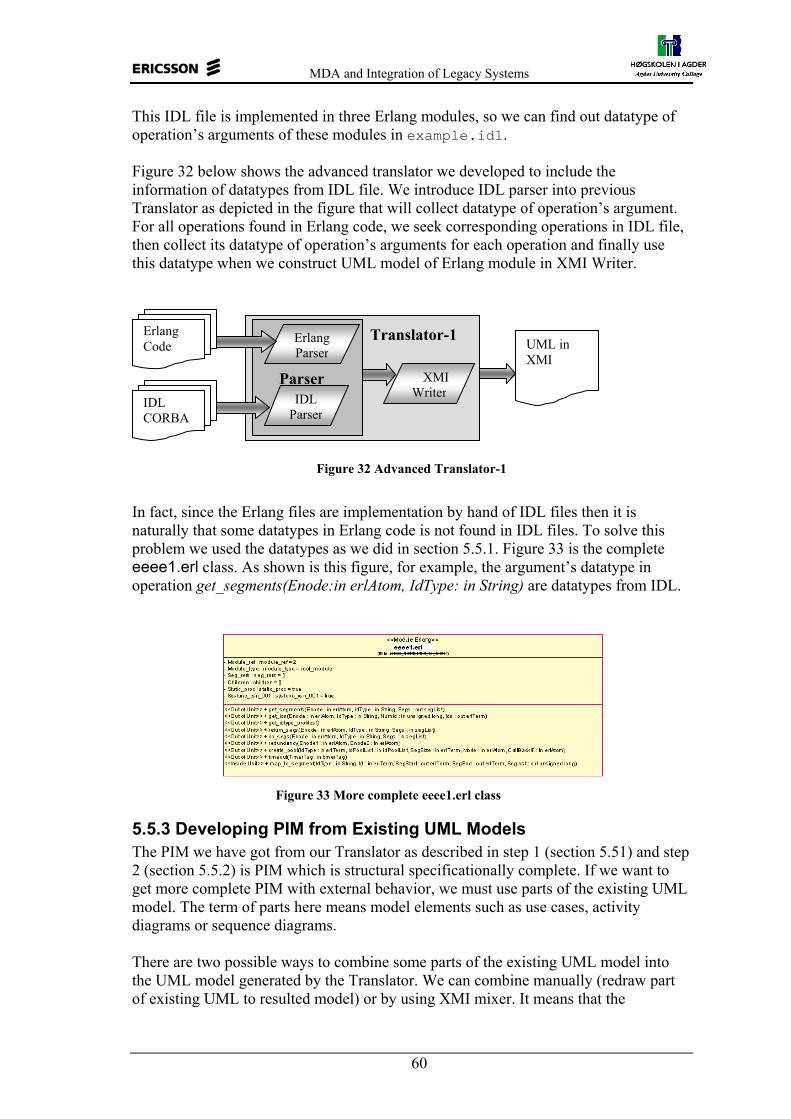
MDA and Integration of Legacy Systems
60
This IDL file is implemented in three Erlang modules, so we can find out datatype of operation’s arguments of these modules in example.idl. Figure 32 below shows the advanced translator we developed to include the information of datatypes from IDL file. We introduce IDL parser into previous Translator as depicted in the figure that will collect datatype of operation’s argument. For all operations found in Erlang code, we seek corresponding operations in IDL file, then collect its datatype of operation’s arguments for each operation and finally use this datatype when we construct UML model of Erlang module in XMI Writer.
Figure 32 Advanced Translator-1
In fact, since the Erlang files are implementation by hand of IDL files then it is naturally that some datatypes in Erlang code is not found in IDL files. To solve this problem we used the datatypes as we did in section 5.5.1. Figure 33 is the complete eeee1.erl class. As shown is this figure, for example, the argument’s datatype in operation get_segments(Enode:in erlAtom, IdType: in String) are datatypes from IDL.
Figure 33 More complete eeee1.erl class
5.5.3 Developing PIM from Existing UML Models The PIM we have got from our Translator as described in step 1 (section 5.51) and step 2 (section 5.5.2) is PIM which is structural specificationally complete. If we want to get more complete PIM with external behavior, we must use parts of the existing UML model. The term of parts here means model elements such as use cases, activity diagrams or sequence diagrams. There are two possible ways to combine some parts of the existing UML model into the UML model generated by the Translator. We can combine manually (redraw part of existing UML to resulted model) or by using XMI mixer. It means that the
Erlang Code
IDL CORBA
XMIWriter
UML in XMI
IDL Parser
Erlang Parser
Parser
Translator-1

MDA and Integration of Legacy Systems
61
Translator must have a mixer that can combines structural and external behavioral aspects of PIM. The following figure shows a method that we propose to develop PIM that contains both of external structural and behavioral aspect as defined SINTEF. The Translator consists of XMI Mixer and PIM Generator. XMI Mixer is used to combine XMI input and PIM Generator will remove PSM information of combined XMI.
Figure 34 XMI mixer and PIM generator
5.5.3.1 XMI Mixer The XMI mixer is used to combine the XMI from individual translation. This means that the whole GSN model can be developed by individual translation of each subsystem and combine all resulted XMIs to construct a whole GSN system. This is because the Translator is designed to translate only in subsystem level. Since the mixer can also be used to combine the models that are created separately, it is possible to combine the models made by different tools since many tools support model exchange in XMI format. We have proved to combine three models that are built by different tools. Two models (model1.mdl and model2.mdl) made with Rational Rose and one model from the translation of Erlang code with our Translator. For complete models, see appendix G about Translator documentation.
5.5.3.2 PIM Generator PIM generated by this PIM generator will be a structural and external behavioral specificationally complete PIM. We will discuss more about this PIM Generator in section 6.3 on future work.
5.6 Summary In our case study, we have presented how to develop a platform independent model from a legacy telecommunication system. The main activity of this process is reverse engineering from existing code (Erlang code in this case) into a UML model. To facilitate this reverse engineering we have developed an Erlang to XMI Translator, which could transform Erlang code into a UML model in XMI format. The UML model generated from reverse engineering is not complete yet because Erlang is not an object-oriented language and does not define datatype. In addition, it is difficult to capture all (internal and external) behavioral features from the code. To improve this UML model we use other sources, which are IDL CORBA files and the existing UML model. Additional information we can get from IDL files is the datatype of operation’s argument. Therefore, we have two sources that are Erlang code and
XMI from Existing UML
XMI from Reverse Engineering PIM
in XMI
XMI
Mixer PIM generator

MDA and Integration of Legacy Systems
62
CORBA IDL as input to the Translator. We propose to use the existing UML to complete the external behavior feature of PIM in the future. We have added another function to the Translator, an “XMI Mixer”, which can combine several UML models (in XMI format). As input of the XMI mixer, we can use both XMI files of the Translator and other XMI files generated by other tools that use XMI version 1.0, UML 1,4 and ISO-8859-1 encoding. We can use this XMI Mixer to build bigger and more complete model from different sources. In appendix G, we show the use of XMI mixer to combine XMI files that contains use case diagram (external behavior).

MDA and Integration of Legacy Systems
63
6 Discussion In this chapter, we present three issues for discussion. The first one is to discuss whether the model result of our case study is a PIM, followed by our suggestion to Ericsson’s software developer about adoption of MDA to develop telecommunication applications based on legacy systems and finally we discussed future work.
6.1 Is the Model a PIM? Since our case study is to study the possibility of developing PIMs, we must analyze whether the model we got from our case study is a PIM or not. It is not an easy task because, as stated in many references, a PIM is relative concept. A model is said to be platform independent if it does not contain any platform specific information/features. However, we have to note that the notion of the platform can be anything from a hardware platform, to operating system, to middleware to another PIM. Hence, the notion of platform and platform independence is relative, which make it possible to have a number of PIMs for the same problem space, each PIM representing a different level of abstraction. A model is also said to be a platform independent if it has a complete structure and model element such as model packaging, class, attribute, operation, datatype of operation’s argument, and all kind of stereotype. A model is also said to be a platform independent just because it can be mapped into multiple platforms and programming languages (for code generation). We can say that the UML model generated by Erlang to XMI Translator is a PIM because we have removed all platform specific information in the parsing process. As we have described in section 5.3.2, we have taken out platform specific information from Erlang code such as transaction handling, communication mechanism, state module etc. In addition, the model is structurally complete with packaging, class, attribute, operation, datatype of operation’s argument, and all kind of stereotype We tried to map the model into Java and C++ programming languages. In appendix F, we present an example of code generating of a UML class generated by the translator, into Java and C++ by Rational Rose.
6.2 Adoption of MDA at Ericsson Based on the results of our study and literatures study about MDA, we can conclude some advantages and disadvantage of using MDA in the software development. Here are some benefits of the MDA approach:
1. Model documentation is always up to date, because changing and developing software system in C and/or Erlang can be reverse engineered into a UML model with the Translator.
2. The same UML model may be used to generate multiple format, target platform and programming language
3. Use of XMI as standard format to model exchange between (MDA) tools shows it’s benefit. Therefore, it is useful when we have a translator to translate the model or implemented code into XMI.
4. During technology changes, conceptual model stay the same.
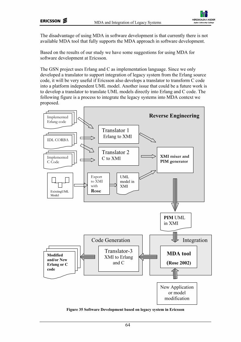
MDA and Integration of Legacy Systems
64
The disadvantage of using MDA in software development is that currently there is not available MDA tool that fully supports the MDA approach in software development. Based on the results of our study we have some suggestions for using MDA for software development at Ericsson. The GSN project uses Erlang and C as implementation language. Since we only developed a translator to support integration of legacy system from the Erlang source code, it will be very useful if Ericsson also develops a translator to transform C code into a platform independent UML model. Another issue that could be a future work is to develop a translator to translate UML models directly into Erlang and C code. The following figure is a process to integrate the legacy systems into MDA context we proposed.
Figure 35 Software Development based on legacy system in Ericsson
Code Generation Integration
Implemented C Code
PIM UML in XMI
IDL CORBA
Modified and/or New Erlang or C code
Translator 2 C to XMI
MDA tool (Rose 2002)
New Application or model
modification
Translator-3 XMI to Erlang
and C
Implemented Erlang code
Translator 1 Erlang to XMI
ExixtingUML Model
Export to XMI with Rose
XMI mixer and PIM generator
UML model in XMI
Reverse Engineering

MDA and Integration of Legacy Systems
65
The method has three blocks; Reverse Engineering, Integration and Code Generation. As shown in figure 35, the reverse engineering process will translate the legacy system (Erlang, C, IDL and the existing UML models) into XMI. The XMI is a platform independent UML model (PIM). With a MDA tool, this XMI can be imported into an UML model to be modified or added with new models. The integration of the XMI file resulted by the reverse engineering process and the new UML model for software evolution is performed in the Integration block. Finally, the modified model can be transformed into code. Since there is no available MDA tool that support full code generation from UML models into C or Erlang, we proposed a translator to generate the code from XMI. This translator should use the old code files (Erlang and C) to generate new code files.
Benefits of this solution are: 1. Model documentation is always up to date. Even if generating a behavior
complete PIM is difficult, we can have an updated structural complete PIM. 2. It is short time to market and low cost. It is because all the implementation
development is based on legacy system.
6.3 Future Work: PIM Generator and UML to Erlang Translator We have developed a translator to translate Erlang into XMI and an XMI mixer to combine XMI resulted by individual translation of Erlang code. The mixer can also be used to combine XMI resulted by translation of Erlang code and XMI resulted by translation of the existing UML model that contains the external behavior aspects. See appendix G for an example of how to combine XMI resulted by translation of Erlang code and XMI that contains use case diagrams. However, this step is just a part of activity in integration of legacy systems. Here are our proposals for future work, see figure 35:
1. Developing Translator 2 to translate C code into a UML model in XMI, 2. Developing Translator 3 to translate UML models in XMI into C and Erlang
codes, and 3. PIM generator. This generator is only needed when behavior aspects of the
existing UML contains PSM features
Since the part of GSN system is also implemented in C, we need a translator to translate this source code into a platform independent UML model in XMI. This part should be combined with the UML model we have got from the translation of Erlang code. The combination process can be done with the XMI mixer we have developed. After we have a translator to translate the Erlang code into XMI and a translator to translate the C code into XMI, we need another translator to generate Erlang and C code from XMI. This kind of the translator should use the existing code as baseline, so it is only the modified parts that should be changed. As we have mentioned in our method that to develop a structural and external behavior specificationally complete PIM, we have to involve the existing UML models as source for external behavioral aspects. The existing UML may contain PSM features that must be removed. Therefore, we need a PIM generator that will remove the PSM features. When the existing UML models (external behavior aspects) do not contain PSM features, we do not need the PIM generator.

MDA and Integration of Legacy Systems
66
7 Conclusion In our thesis, we have explained and demonstrated using MDA approach to support the integration of legacy systems in a telecommunication application. We have developed a platform independent UML model from a part of the GSN system used at Ericsson that is implemented in Erlang.
The important step in the integration of the legacy systems is reverse engineering of the implemented code into the MDA context in form of a UML model. In order to perform the reverse engineering process we have developed an Erlang to XMI Translator that can transform Erlang code into UML models in XMI. Based on our study about which aspects should be specified in PIM and which aspects are left to code, we only took out structural aspects of PIM such as model packaging, class, attribute, operation, operation’s argument, datatype, stereotype and dependencies in the translator, while PSM features are left for coding. The translator has an additional function that can combine several UML models (in XMI) into a bigger and more complete model.
The UML model resulted by the Erlang to XMI Translator is a PIM. It is because we have removed all platform specific information from source code in the parsing process. This kind of PIM can be said as a structural specificationally complete PIM since the model is structurally complete with model packaging, class, attribute, operation, operation’s argument, datatype, stereotype and dependencies. Other possible PIM that can be developed from the existing UML models, IDL and code is a structural and external behavioral specificationally complete PIM. It is hard even impossible to get a more complete PIM that include the internal behavior aspects since these aspects are best expressed detail in code.
By using our method to develop PIM from the source code, CORBA IDL and the existing UML, Ericsson and other readers can expand the PIM developing process to obtain a more complete PIM that involves all structural and behavioral aspects. These issues can become sources for further research and study in software development, especially software development for telecommunication applications at Ericsson.
Benefits of adopting an MDA approach in software development at Ericsson are: − Model is always up to date, because with MDA concept, changing and
developing software system is done in the model and then transformation and code generator are used to produce code. In addition, changing in the code can be reverse engineered to get the updated of the UML model. Even if generating a behavior complete PIM is difficult, we can have an updated structural complete PIM.
− UML models are easier to read and understand than source code. − The conceptual model stays the same, when technology changes. The same UML
model may be implemented into multiple platforms and programming languages.
Many industries and research groups propose the MDA tools that support reverse engineering, but over this time, there is not available tool that fully supports the MDA specification. The reverse engineering issue and the "mining" process of the PSM to PIM mapping are only described vaguely in the MDA related documents. Although the MDA still has quite a way to go, the concept is already used and will give benefits to software development process.

MDA and Integration of Legacy Systems
67
Abbreviations and Glossary BFOP Business Function Object Patterns CCM CORBA Component Model OCL Object Constraint Language COMET Component and Model based development METhodology. CORBA Common Object Request Broker Architecture COTS Commercial-Off-The-Shelf CWM™ Common Warehouse Meta-model DTD Document Type Definition EAI Enterprise Application Integration ECA Enterprise Collaborative Architecture EDOC Enterprise Distributed Objects Computing GGSN Gateway GSN GPRS General Packet Radio Service GSN GPRS Service Node HLP High Level Package IDL Interface Definition Language J2EE Java 2 Enterprise Edition JCP Java Community Process MDA™ Model-Driven Architecture™ MDC Meta-Data Coalition MMM Model Middleware Maintenance MOF™ Meta-Object Facility OMG Object Management Group PIM Platform Independent Model PSM Platform Specific Model ROI Return on Investment SAD Software Architecture Description SGSN Serving GSN TMN Telecommunication Management Network TSAS Telecommunication Services Access and Subscription UML™ Unified Model Language UMT UML Model Transformation Tool WPP Wireless Packet Platform WSDL Web Services Description Language XML eXtensible Markup Language XMI XML Metadata Interchange XSL eXtensible Stylesheet Language XSLT XSL for Transformation Structural aspect of UML = class, class diagram, package, relationships (association,
dependency, realization, generalization), interface, types, role, instances and object diagram.
Behavioral aspect of UML= interaction, interaction diagram, use case, use case diagram, activity diagram, event and signals (operations), state machine, process and thread, action semantic and state chart diagram.

MDA and Integration of Legacy Systems
68
Structural specificationally complete PIM = Platform independent UML model that has complete structural aspect and follow UML specification.
Structural and Behavioral specificationally complete PIM = Platform independent UML model that has complete both of structural and behavioral aspects, and follow UML specification
Specificationally complete PIM = a complete model of the system specification – the external architectural structure and behavior – of a component system in terms of a business model, a requirements model and an architecture model.
Computationally complete PIM = a complete model which adds to a specificationally complete PIM a definition of the system realization – the internal design structure and behavior – of a component system in terms of a design model. The design model is expressed using an action semantics language

MDA and Integration of Legacy Systems
69
References [1] Call for presentation for MDA™ Implementers' Workshop: May 12-15, 2003,
Succeeding with Model Driven Systems Orlando, Florida, USA, http://www.omg.org/news/meetings/MDA2003/call.htm
[2] Kath, Olaf, 2002, Impacts of Changes in Enterprise Software Construction for Telecommunications Model Driven Architecture – Assessments of relevant technologies, EURESCOM Project, IKV++ Technologies AG.
[3] Herzog, Michael, 2002, Impacts of Changes in Enterprise Software Construction for Telecommunications Model Driven Architecture – Adaptation and Impact for Telecom Domain. EURESCOM Project,, Telekom AS, Deutsche
[4] C. Stephen, M. Simon, R. Kerry, 2002, Meta-Object Facility Tutorial, http://www.dstc.edu.au/Research/Projects/MOF/ accessed January 2003.
[5] G. Caplat, Jean Louis, 2001, Model Mapping in MDA, INSA, Bat. Blaise Pascal F69621 Villeurbanne Cedex, France.
[6] OOPSLA Workshop 2002, Generative Techniques in the context of Model Driven Architecture, Washington, USA. www.softmetaware.com/oopsla2002 accessed January 2003.
[7] J.P. Wadsack, and J.H. Jahnke 2002, Toward Model Driven Middleware Maintenance. In the OOPSLA 2002 Workshop Generative Techniques in the Context of Model Driven Architecture, November 4-8 2002, Washington, USA. http://www.softmetaware.com/oopsla2002/jahnkej.pdf accessed January 2003.
[8] Miller, Joaquin and Mukern, Jishnu, 2001, Model Driven Architecture, Object Management Group, http://www.omg.org/cgi-bin/doc?ormsc/2001-07-01 accessed January 2003.
[9] Object Management Group: MDA Specifications, OMG official website at http://www.omg.org/mda/specs.htm accessed December 2002.
[10] Object Management Group: MDA Overview, OMG official website at http://www.omg.org/mda/executive_overview.htm accessed December 2002.
[11] Siegel, Jon Ph.D., 2001, "Developing in OMG's Model Driven Architecture (MDA)". OMG’s White Paper Revision 2.6 http://www.omg.org/mda accessed January 2003.
[12] Object Management Group: http://www.omg.org/mda accessed January 2003.
[13] Mellor, S.J., 2002, Executable UML: A Foundation for Model Driven Architecture, Addison Wesley. Boston, USA.
[14] Sommerville, Ian, 2001, Software Engineering, Addison Wesley, USA
[15] Rational Unified Process whitepaper, 1998, Rational Unified Process: Best Practices for Software Development Teams, www.rational.com accessed January 2003.
[16] Object Management Group: 2002, UML profiles for CORBA Specification,
[17] Object Management Group: 2002, UML profiles for EDOC Specification

MDA and Integration of Legacy Systems
70
[18] K. Thomas, 2002, Model Driven Architecture, Interactive Objects Software GmbH, published in ObjektSpektrum, Deutsche
[19] Summary of UML tools Features, www.jeckle.de/umltools.htm accessed January 2003.
[20] Object Management Group official website at http://www.omg.org accessed January 2003.
[21] M., Miguel, J. et.al., 2002, Practical Experiences in the Application of MDA, UML Conference proceeding, Springer-Verlag Berlin.
[22] G., Anna, L., Michael, et.al., Transformation: The Missing Link of MDA CRC for Enterprise Distributed Systems, DSTC, Australia www.dstc.edu.au/Research/Projects/Pegamento/ publications/icgt2002.pdf.
[23] D. Varro, G. Varrao, and A. Patarica., Designing the Automatic Transformation of Visual Languages http://www.inf.mit.bme.hu/FTSRG/Publications/TR-12-2000.pdf, accessed January 2003.
[24] B., Arne-Jørgen, E. Brian, Ø.A. Jan, 2002, Methodology Handbook with documentation of the COMET meta-models, Affiliation: SINTEF Telecom and Informatics, Norway, www.sintef.no
[25] Kulandaisamy, P.D.J., Nagaraj, N.S., Thonse, S., 06th September 2002, Representing Procedural Source in UML, SETLab Infosys Technology Limited, Bangalore, India, www.omg.org/news/meetings/workshops/UML2002-Manual/04-2_Reverse_Engineering_Procedural_Code_using_UML.pdf
[26] Mos, Adrian and Murphy, John, 2002, A Framework for Performance Monitoring, Modeling and Prediction of Component Oriented Distributed Systems, Dublin City University, Ireland, ACM proceeding October 2002.
[27] Booch, G., Rumbaugh, J., Jacobson, I., 1998, The Unified Modeling Language User Guide, ISBN 0-201-57168-4, Addison Wesley, USA
[28] Belaunde, Mariano, December 2002, MODA-TEL, Initial Identification of issues for further research, MODA-TEL Consortium, France Telecom, France, http://www.modatel.org/~Modatel/pub/deliverables/D2.2-final.pdf.
[29] Azad Technology, Overview of Object OrientedConcept, Term and Experience, www.azadtech.com accessed January 2002.
[30] Marvie, R., Merle,P.,2002, CORBA Component Model: Discussion and use with OpenCCM, Laboratoire d’informatique Fondamentale de Lille UPRESA, CNRS, France
[31] Lars E. and Per-Martin H., 2002, GPRS support nodes overview,Ericsson, Grimstad, Norway.
[32] Telelogic Tau documentation, www.telelogic.com
[33] ArcStyler documentation, http://www.io-software.com/
[34] Objecteering documentation, www.objecteering.com
[35] Poseidon http://www.gentleware.com/
[36] iUML user guide, www.kc.com

MDA and Integration of Legacy Systems
71
[37] Kabira http://www.kabira.com
[38] UMT website, http://www.modelbased.net/
[39] Serrano, M.A., Oca, C.M., Carver,D.L., Evolutionary Migration of Legacy System to an Object-Based Distributed Environment, Department of Computer Science, Louisiana State University, USA.
[40] XSL Transformations (XSLT) Version 1.0 W3C Recommendation 16 November 1999, http://www.w3.org/TR/1999/REC-xslt-19991116.html.
[41] Component-Based Software Development / COTS Integration, http://www.sei.cmu.edu/str/descriptions/cbsd.html

MDA and Integration of Legacy Systems
72
Appendix A Thesis definition Supervisor: Parastoo Mohagheghi (Ericsson, NTNU) and Jan P. Nytun (HiA). Student(s): Selo Sulistyo, Warsun Najib
Responsible line manager: Gunn Marit Eriksen Thesis Title: MDA and Integration of Legacy Systems Subtitle: Background: The Model Driven Architecture (MDA) addresses the challenge of constantly changing infrastructure and promotes application and component reuse and portability. The success of MDA depends highly on integration of legacy systems in a MDA context. This activity may include reengineering of code or transforming existing UML models. Thesis definition: The objectives of the thesis are:
• Study which aspects of the context system (a real-time distributed telecommunication application) that can be specified in a Platform Independent Model (PIM) and which aspects are left for a Platform Specific Model (PSM) and coding.
• Study the possibility of developing a PIM model for the legacy system using the existing UML model, component specifications in IDL and other artefacts.
Competence: Object-Oriented analysis and design using UML. During the work, the student(s) will learn more about MDA. Security: Ericsson should approve access to the UML models needed to perform a case study in the GPRS project. Ericsson should approve whether all the thesis or parts of it will be available for public access. Therefore it is required to deliver a final version to Ericsson before the deadline for presentations and delivery to HiA for approval. Originality, IPR and reuse: Limitations: It is required to write the thesis in English.
Activities: Main activities are described in the definition. A more detailed activity list and time plan will be made later. Prerequisites: Working place and conditions: The students need an office and user account during spring 2003 to study the UML model. Budget and funding: References:
• www.omg.org/mda
• Executable UML: A Foundation for Model-Driven Architecture Stephen J. Mellor, Marc J. Balcer © 2002 / 0-201-74804-5 / Addison Wesley Professional

MDA and Integration of Legacy Systems
73
Appendix B GSN Model
B-1 GSN Model Structure See in CDROM.
B-2 GSN meta-model See in CDROM.
Appendix C CORBA IDL: mac.idl See in CDROM.
Appendix D Erlang Code: macal.erl See in CDROM.
Appendix E XMI and UML E-1 XMI of UML Model for Model Exchange See in CDROM
E-2.a XMI of MPS Subsystem See in CDROM
E-2.b UML Model of MPS Subsystem See in CDROM
E-3.a XMI of NCS Subsystem See in CDROM
E-3.b UML Model of NCS Subsystem See in CDROM
E-4.a XMI of MPS and NCS Combination See in CDROM
E-4.b UML Model of MPS and NCS Combination See in CDROM
Appendix F Model Testing See in CDROM
Appendix G Erlang to XMI Translator
G-1 Class Diagram See in CDROM.

MDA and Integration of Legacy Systems
74
G-2 Implementation Code See in CDROM.
G-3 Documentation of Erlang to XMI Translator EXT logo
Figure g-1 EXT logo Installing:
− Copy the Translator.zip file from CD − Extract it into directory C:\Translator − If you want to install to another directory otherthan C:\Translator, you have
to modify run.bat file. Running:
− After the translator is installed you can run the software by double click run.bat
− Output files will be located in the Translator directory. − The name of the XMI output file will be the same as the name of selected
file or directory. Requirements:
− To open the XMI output file from the translator we use Rational Rose. − Rational Rose needs Rose to XMI plugins in order to open XMI files. The
plugins can be downloaded from rational website (www.rational.com). − We use Rose XMI plugins version 1.3.4. To install this plugins, follow
instructions from downloaded files. − To be able to open XMI files, the XMI file that will be opened must be
located in same directory where DTD files located. This directory is inside XMI plugins directory installation.

MDA and Integration of Legacy Systems
75
Main Menu Screen shot Here is the main window when Erlang to XMI Translator is started:
Figure g-2 Translator has three main menus which located in the File menu:
1. Transform to Class is used to transform the Erlang Module (directory or file) into a class diagram in XMI.
2. Transform to Interface is used to transform the Erlang Module (directory or file) into an Interface in XMI.
3. Combine XMI is used to combine the XMI results. This mixer can also used to combine with the XMI files generated by Rose2000.
Translate to XMI Menu After you have selected and clicked on the “Transform to Class” menu, a window will appear that ask s for the directory to transform (sub system, block unit or single Erlang module). This is the default directory. Figure g-4 shows that NCS directory is selected to be transform to XMI. The file output is named NCS.xml.
Figure g-3 Then you can click the Open button to run the Translator. The Translator should work and display as following:

MDA and Integration of Legacy Systems
76
Figure g-4 Command line display. This figure shows the process of translation where the translator parses the operation’ arguments in IDL file. After the process is completed, the following report will be displayed. The file output is located in the directory where you placed the Java code.
Figure g-5 Report for Translation of subsystem NCS Combine XMI Menu
Since the GSN model is too big to be translated in one try, we develop the “Combine XMI” menu. This menu is used to combine the XML files generated by the Translator or Rose. The combine XMI process integrates models that are made separately. It is possible to combine the XMI files that are generated by the Translator or by Rose, or between Rose’s models or between XMI resulted by Translator. Figure g-6 shows the combine menu.
Figure g-6 Combine menu

MDA and Integration of Legacy Systems
77
After you clicked the Combine menu, the following Frame will appear.
Figure g-7 Input dialog frame
Then you can fill in the name of file output, package and stereotype. If you do not fill in the field then the system will use the default name as follow: output.xml for output file, package for package and none for stereotype. After you click OK the following figure will appear
Figure g-8 Dialog frame to select files
You can then select multiple xml files by using of CTRL + click. In figure 3, I have chosen NCS.xml and MPS.xml. Then click open, and the following figure should be shown
Figure g-9

MDA and Integration of Legacy Systems
78
Open output XMI in Rational Rose You can then open the output.xml with Rose. Example of the result when we open XMI files generated by translator in Rose, can bee seen in CDROM. The Translator can also be used to combine the XMI resulted by export process from Rose as well. The following is an example where I combine the 3 models. Two models is made with Rose (ModelRose3.mdl and modelRose.mdl) and one model is resulted by Translator (nrhlob.xml from Erlang). 1. Model 1: ModelRose3.mdl
Figure g-10 2. Model 2 : modelRose.mdl
Figure g-11

MDA and Integration of Legacy Systems
79
3. nrhlob.xml opened with Rose model.
Figure g-12
4. The result: combined.xml
Figure g-13 About the Translator
1. The Erlang parser can generate a complete class if the structure of source code (Erlang) follows the Erlang template defined in the GPRS project.
2. The names of the classes refer to the Erlang files names with their extension. We could not omit the extension because there is found hrl files that have the same name with the Erlang files in the same package. This will cause duplicated class name if we omit the extension.
3. Not all datatypes can be found in the same subsystem, some datatypes of the operation’s arguments use datatypes from other subsystems.
4. Operations have various type return value, sometimes the return value is to call another operation in other block or subsystem. We did not handle the return value.