MCWP 4-11 4-11.6 Bulk... · MCWP 4-11.6 Bulk Liquids Operations ... subordinate commanders, and...
81
MCWP 4-11.6 Bulk Liquids Operations U.S. Marine Corps PCN 143 000009 00
Transcript of MCWP 4-11 4-11.6 Bulk... · MCWP 4-11.6 Bulk Liquids Operations ... subordinate commanders, and...
MCWP 4-11.6
Bulk Liquids Operations
U.S. Marine Corps
PCN 143 000009 00
DEPARTMENT OF THE NAVYHeadquarters United States Marine Corps
Washington, DC 20380-1775
29 August 1996
FOREWORD
1. PURPOSE
Marine Corps Warfighting Publication (MCWP) 4-25.5, Bulk Liquids Operations, providesdoctrinal guidance for bulk liquids support of the MAGTF. This publication is aligneddoctrinally with FMFM 4, Combat Service Support and tactically with FMFM 4-1, CombatService Support Operations. It specifically addresses the techniques and procedures of bulk fueland water support of the FMF and the MAGTF in a joint/multinational environment. MCWP4-25.5 is a follow-on publication of FMFM 13, MAGTF Engineer Operations.
2. SCOPE
This publication provides information on the bulk liquids mission, organization, and concept aswell as guidance for the planning and conduct of bulk fuel and water support operations forcommanders, staffs, subordinate commanders, and personnel in bulk liquid units.
3. SUPERSESSION
Not applicable.
4. CHANGES
Recommendations for improving this manual are invited from commands as well as directlyfrom individuals. Forward suggestions using the User Suggestion Form format to—
COMMANDING GENERALDOCTRINE DIVISION (C42)MARINE CORPS COMBAT DEVELOPMENT COMMAND3300 RUSSELL ROAD SUITE 318AQUANTICO, VIRGINIA 22134-50215
5. CERTIFICATION
Reviewed and approved this date.
BY DIRECTION OF THE COMMANDANT OF THE MARINE CORPS
PAUL K. VAN RIPER Lieutenant General, U.S. Marine Corps
Commanding General Marine Corps Combat Development Command
DISTRIBUTION: 143 000009 00
Record of Changes
ChangeNo.
Date ofChange
Date ofEntry Organization Signature
v (reverse b lank)
Overview of Bulk Liquids Operations
Water and fuel make up the greatest quantities of supply required by the Marine air-ground task force (MAGTF) to conduct modern warfare. As petroleum or water re-quirements rise above individual or small unit needs, it becomes necessary to handlethem in “bulk” form. Bulk handling calls for special equipment, product handlingsafeguards, and standing operating procedures (SOPs). Plant account/permanent fa-cilities are often used at bases, camps, and air stations; however, deploying MAGTFsrequire special expeditionary systems. See chapter 3 for discussion on tactical fuelsystems (TFSs). This publication will address water and fuel as functional operations.For discussion of water and fuel supply classes, see MCWP 4-6.
Mission success depends on planning for the known and expecting the unknown. Thisis especially true when planning bulk liquids operations. See part I for bulk fuel op-erations and part II for bulk water operations. Commanders and their staffs at all lev-els must be concerned about maintaining water and fuel support to allow completionof the unit’s mission. To provide the most effective use of bulk liquids stocks andequipment, bulk liquids planners must be familiar with Marine Corps and Departmentof Defense (DOD) bulk liquids assets and responsibilities. To ensure adequate sup-port, commanders and their staffs should address planning for these two commoditiesin all operation plans (OPLANs).
Petroleum and water are supplied as either packaged or bulk products. Packagedproducts differ from bulk products in one respect—the product is received along withthe container in a packaged product. Fuel and water are combat-essential bulk com-modities that are no longer only supplied by 5-gallon cans or packaged supply meth-ods. Packaged methods require extensive shipping space and provide a reducedthroughput capability when compared to “bulk” operations. The current MarineCorps and DOD policy is that packaged or drummed fuel (and water) is not the pre-ferred method of providing bulk liquids. With the many drawbacks to using packagedor drummed products, the use of packaged or drummed fuel (and water) shouldbe kept to a minimum.
Bulk liquids are defined as petroleum or water products which are normally trans-ported by pipeline, rail tank car, tank truck barge, or tanker and stored in tanks orcontainers having a capacity of more than 55 gallons. The exceptions are fuels or wa-ter stored in 500-gallon collapsible containers which are considered to be packaged.MAGTF commanders and staff planners need to be aware of and should consider themany options available in bulk liquids operations. Mission success may hinge onproper planning and handling of these complex and dynamic commodities.
(reverse blank)
User Suggestion Form
From:
To: Commanding General, Doctrine Division (C42), Marine Corps Combat Development Command, 3300 Russell Road Suite 318A, Quantico, Virginia 22134-5021
Subj: RECOMMENDATIONS CONCERNING MCWP 4-25.5, BULK LIQUIDS OPERATIONS
1. In accordance with the Foreword to MCWP 4-25.5, which invites individuals to submit suggestionsconcerning this MCWP directly to the above addressee, the following unclassified recommendation isforwarded:
____ _________________ _______ ______________Page Article/Paragraph No. Line No. Figure/Table No.
Nature of Change: Add
Delete
Change
Correct
2. Proposed new verbatim text: (Verbatim, double-spaced; continue on additional pages as necessary.)
3. Justification/source: (Need not be double-spaced.)
NOTE: Only one recommendation per page.
iii (reverseblank)


Record of Changes
Change No.
Date of Change
Date of Entry Organization Signature
v (reverse blank)
Bulk Liquids Operations
Table of Contents
Page
Overview of Bulk Liquids Operations
Part I. Bulk Fuel Operations
Chapter 1. Introduction
1001. History of Bulk Fuel 1-11002. Concept of Bulk Fuel Operations 1-2
Chapter 2. Bulk Fuel Organization
2001. Organization and Responsibilities 2-12002. Miltary Services 2-2
Chapter 3. Tactical Fuel Systems
3001. Amphibious Assault Fuel System 3-13002. Tactical Airfield Fuel Dispensing System 3-13003. Helicopter Expedient Refueling System
3-23004. Expedient Refueling System 3-23005. SIXCON 3-23006. M970 Mobile Refueler 3-23007. Tactical Petroleum Laboratory-Medium 3-33008. USMC Aircraft Bulk Fuel Handling Systems 3-33009 Joint Service Interoperability 3-3
Chapter 4. Bulk Fuel Planning
4001. Planning Requirements for Bulk Fuel 4-14002. Planning Considerations 4-2
vii

Page
4003. Planning Categories 4-24004. Planning for Joint Bulk Fuel Operations 4-24005. Marine Corps Bulk Fuel Planning 4-34006. War Reserve Requirements and Stocks 4-5
Chapter 5. Bulk Fuel Theater Operations
5001. Developed Theater 5-15002. Undeveloped Theater 5-15003. Phases of Bulk Fuel Operations
5-25004. Bulk Fuel Operations Within the MAGTF 5-35005. Bulk Fuel Support for the MAGTF 5-45006. Maritime Prepositioning Ships 5-55007. Bulk Fuel Reports 5-6
Chapter 6. Bulk Fuel Inventory Management
6001. References 6-16002. Inventory Management Procedures 6-16003. Fuel Accountability 6-26004. Reports 6-26005. Wartime Accounting 6-3
Chapter 7. Bulk Fuel Quality Surveillance
7001. Quality Assurance Program 7-17002. Marine Corps Quality Assurance Program 7-17003. Deterioration Limits 7-27004. Reclamation 7-27005. Captured Fuel 7-3
Part II. Bulk Water Operations
Chapter 8. Introduction
8001. History of Bulk Water 8-18002. Concept of Bulk Water Operations 8-2
viii
MCWP 4-25.5

PageChapter 9. Water Equipment
9001. Water Equipment End Items 9-19002. Family of Water Supply Support Systems 9-2
Chapter 10. Water Support Planning
10001. Planning Guidance 10-110002. Water Requirements 10-110003. Consumption Requirements 10-2
Chapter 11. Water Support Operations
11001. MAGTF Water Support 11-111002. MAGTF Water Support Responsibilities 11-111003. Water Purification 11-211004. Water Storage 11-211005. Water Distribution 11-211006. Host Nation Considerations 11-3
Appendix A. POL Appendix A-1
Appendix B. POLALOT Message Text Format Report B-1
Appendix C. POLRQMT Message Text Format Report C-1
Appendix D. REPOL Message Text Format Report D-1
Appendix E. Environmental Regulations E-1
Appendix F. Glossary F-1
Appendix G. References and Related Publications G-1
ix (reverse blank)
MCWP 4-25.5
1001. History of Bulk Fuel
a. Metz, 1944—Fuel Shortage. During the en-gagement of Metz in 1944, the shortage of fuel in theThird Army was a significant factor. Beginning the pursuiton 1 August 1944 with a 1.5 million-gallon reserve, theThird Army depleted its stockpile by 7 August and had tooperate on a “hand-to-mouth” basis. While the fast-pacedpursuit is often blamed for Third Army’s high fuel use, in-accurate forecasts of consumption were also a significantcause. The 6th Armored Division, for example, used twoto three times more fuel than anticipated.
While Patton was racing through France and consumingan average of 350,000 gallons of fuel each day, the famousRed Ball Express was organized to meet his growing de-mands as well as those of the First Army. The Red BallExpress was a nonstop convoy of trucks that connectedsupply depots in Normandy with the armies in the field.At its peak the Red Ball Express used 6,000 trucks andburned 350,000 gallons of fuel per day to complete itsmissions. As Patton advanced deeper, the demands placedupon the Red Ball Express grew faster than it was able tosupply. It became obvious to tactical commanders that theAllies were running out of gas. On 28 August, LtGen Pat-ton summed it up this way, “At the present time ourchief difficulty is not the Germans, but gasoline. If theywould give me enough gas, I’d go all the way to Berlin.”
Patton’s army was forced to ease up when its fuel alloca-tion fell 100,000 gallons short. Even though fuel was in abundance in Normandy, the Red Ball Express could nottransport it in sufficient quantities to the Third Army’s for-ward units. On 31 August after receiving no fuel at all,Patton’s spearheads came to a halt.
b. Korean Conflict—Fuel Packaging and Mov-ing Problems. During World War II, the fuel needs ofthe Marine Amphibious Forces were barely met with5-gallon cans and 55-gallon drums. The problem escalatedwhen beach personnel were tasked to move this fuel. Theimportance of packaging and moving petroleum productscontinued to increase in the Korean Conflict where a largepercentage of all supply tonnage consisted of petroleumproducts. To meet this growing requirement, the MarineCorps Equipment Board developed a concept in 1952 forfuel delivery in amphibious operations. This concept calledfor using collapsible tanks, rubber hose, and portablepumps to provide bulk fuel support. The concept provedworkable and evolved into the fuel systems that we use to-day—the amphibious assault fuel system (AAFS), the tac-tical airfield fuel dispensing system (TAFDS), and thehelicopter expedient refueling system (HERS). The basicand most significant feature of the three systems was andstill is flexibility.
Part I. Bulk Fuel Operations
Chapter 1
Introduction
Procurement of fuel for the United States Armed Forces can be traced back to theRevolutionary War. Late in November 1775, the Continental Congress resolvedthat the troops were to be supplied with fuel and bedding. The QuartermasterGeneral was responsible for providing wood, straw, and blankets as well as campequipage. The requirements for fuel, as we know it today, remained relativelysmall until World War I. In 1918 after the Armistice, Lord Curzon said, “TheWorld War was won for the allies not only by blood but by oil.” Winston Chur-chill declared, “The allies had floated on a sea of oil to victory.”

c. Vietnam War—Implementing the New FuelSystems. During the Vietnam War, the AAFS, theTAFDS, and the HERS were successfully combat-testedfrom the 17th parallel south to the Mekong Delta. The ma-jority of fuel issued to Marine Corps units was issuedthrough either AAFS or TAFDS. The AAFS fuel farm atChu Lai consisted of 120 10,000-gallon fuel tanks or 1.2million gallons of fuel. This system operated fromSeptember 1965 until 1968 when the Navy installed rigidtanks and assumed responsibility for the operations. Mili-tary petroleum consumption during the Vietnam Warpeaked in 1969 at 398 million barrels, dropping to 211million barrels in 1974. Even in a limited, jungle-typewar, petroleum played a major logistic role. d. Southwest Asia (SWA) 1990-91—MoreImprovement of Fuel Systems. Since Vietnam, theMarine Corps has continued to improve and increase thecapabilities of the TFSs. Operations Desert Shield and De-sert Storm provided the toughest challenge to date for theMarine Corps bulk fuel community. From August 1990through February 1991, U.S. land-based operations inSWA consumed approximately 1.8 billion gallons of fuel.The Marine Corps used approximately 81 million gallonsduring SWA, and bulk fuel support played a major role inthe Marine Corps’ success.
Modern warfare requires tremendous quantities of fuel.For every ten Marines on the battlefield, there are approxi-mately four fuel-consuming items of equipment. Methodsand equipment for supplying fuel to the customer are con-stantly being updated, ensuring that the Marines of todayare able to perform their mission.
1002. Concept of Bulk Fuel Operations
Bulk fuel support is a joint venture. While bulk fuel man-agement for joint operations is the ultimate responsibilityof the commander of the joint command, each Service isresponsible for support of its forces and any other missionsassigned by the joint commander. The actual proceduresused to provide bulk petroleum support to the Services willdepend on conditions in the area of operations (AO), e.g.,a developed theater or an undeveloped theater.
a. Developed Theater. A mature or developed thea-ter will usually have host nation assets available such aspipelines, storage facilities, and railways that will help sup-port the bulk petroleum distribution system. Airbases, tac-tical airfields, and Service bed-down sites will be
supported by pipelines whenever tactically feasible. Thepipeline and/or hoseline system will extend as far forwardas possible.
b. Undeveloped Theater. In the undeveloped theater,host nation or commercial bulk fuel facilities normally willnot be available and tactical assets will have to be used.The bulk fuel supply system in the undeveloped theatermay include limited tanker mooring systems, floatinghoselines, submarine pipelines, inland tank farms,hoselines, and collapsible tanks.
c. Resupply. Bulk fuel resupply is managed in the uni-fied commander in chief (CINC) Joint Petroleum Office(JPO). The CINC JPO coordinates all agreements con-cerning bulk fuel support between component commandsand host nations. For the majority of places that Marineforces will be employed, Marines will have to make maxi-mum use of their organic bulk fuel equipment. However,when available, existing pipelines and storage systems willbe used to receive, store, and provide bulk reduction offuel stocks to the maximum extent possible. Host nationassets will be used to augment U.S. transportation andbulk fuel distribution capabilities. Once resupply lines ofcommunications are established, the JPO will make prepa-rations for resupply from CONUS pushed stocks and/orfrom theater source stocks (i.e., contracted from theater re-fineries), as coordinated by either the joint task force (JTF)or the Marine component commander.
d. Marine Forces. Marine forces will obtain initial pe-troleum supply support from operating stocks carriedaboard maritime prepositioning ships (MPS), assault eche-lon (AE) and assault follow-on echelon (AFOE) shipping(including landing forces operational reserve material(LFORM)), and in-theater bulk petroleum war reservestocks (BPWRS) stored in selected storage depots through-out the theater. Additionally, maximum use will be madeof available host nation support bulk fuel supply systemsand stocks as negotiated in standing host nation supportagreements. Due to the lack of tanker offloading facilitiesin many areas, U.S. Navy ship-to-shore capabilities mayhave to be utilized. Employment of the U.S. Navy off-shore petroleum discharge system (OPDS) and amphibi-ous assault bulk fuel system (AABFS) in conjunction withthe USMC AAFS will be required to meet Marine Corpsneeds. Arrangements for this are coordinated by the Ma-rine component commander or Marine expeditionary force(MEF).
1-2 MCWP 4-25.5
e. Inland Distribution. Depending upon the situation,inland distribution of bulk fuel will be by tactical pipelineas much as possible and by mobile refuelers as required.Whenever possible, petroleum distribution to the airfieldswill be by tactical hoseline from the AAFS to the TAFDS.Mobile refuelers will be used if required to transport bulkfuel to the airfields.
Bulk fuel support will be provided on a “push” basis toensure the capability of continuous operations. The basicoperating concept is to keep storage tanks full at all times.
The schedule for movement of fuel through the distribu-tion system is based on ullage (the amount by which acontainer, storage tank, or storage facility falls short ofbeing full) and anticipated product demand. For MarineCorps retail bulk fuel operations, bulk fuel will bepumped/transported from the main AAFS tank farm to thecombat service support detachment (CSSD) tank farms.The CSSD tank farms will provide bulk reduction to theusing unit’s equipment or mobile refuelers. Movement offuel from the CSSDs will be by any means available.
(reverse blank)
Bulk Liquids Operations 1-3

2001. Organization and Responsibilities
a. Defense Fuel Supply Center. The DFSC, acomponent of the DLA, is the DOD integrated materialmanager for bulk petroleum products. The DFSC is re-sponsible for procurement of bulk petroleum products andrelated services and maintains the product until it is deliv-ered to the supported Service. To provide timely and effi-cient support to the Services, the DFSC has establishedarea defense fuel regions (DFRs). These regions provideclose contact and coordination with the Services. TheDFRs are located in CONUS, Pacific Command (PA-COM), European Command (EUCOM), and the DFR,Middle East. In CONUS, DFR personnel order productsfrom contractors, distribute products to the Services, andperform contract administration. Overseas, DFR personnelprovide product ordering and contract administration. Themissions and general functions of the DFSC DFRs areoutlined in detail in DOD 4140.25M, Department of De-fense (DOD) Management of Bulk Petroleum Products,Natural Gas and Coal and DOD 4140.25 (directive),Management of Bulk Petroleum Products, Storage, andDistribution Facilities, Volume I, Chapter 2.
b. Unified Commands. In unified commands, staffplanning and management for bulk petroleum is performedin the J-4 JPO. The JPOs are normally staffed by person-nel from each Military Service having a mission in the
theater. The JPO coordinates the theater bulk petroleumoperations and provides the interface between DFSC andthe Service theater bulk petroleum managers. Service thea-ter bulk petroleum managers provide Service bulk petro-leum requirements to the JPO. The JPO consolidates therequirements for all the Services and schedules deliveriesfor the theater. The JPO advises the theater commanderand staff on bulk petroleum logistic planning and policymatters. When required, the JPO advises the CINC on theallocation of bulk petroleum products and facilities.
Bulk petroleum management for the entire theater is the ul-timate responsibility of the commander of the unified com-mand through the JPO. Daily management isaccomplished by the JPO in coordination with the Serv-ices. The unified command may also establish sub-area pe-troleum offices (SAPOs) at the subunified command levelto provide in-country or regional staff managementfunctions.
c. Joint Bulk Fuel Support. During joint operations,bulk fuel management for the entire force is the ultimateresponsibility of the joint commander. Daily managementis accomplished by the JPO or JTF petroleum staff office,in coordination with the inland distribution manager, Serv-ice retail managers, DFSC, and applicable host nation ac-tivities. The joint commander makes the final decision onthe appropriate way to accomplish bulk fuel storage and
Chapter 2
Bulk Fuel Organization
On 1 July 1973, the Defense Logistics Agency (DLA) assumed centralized manage-ment of bulk petroleum within the DOD. The Defense Fuel Supply Center (DFSC)was designated the integrated material manager of U.S. military bulk petroleum.The CINCs have established JPOs to discharge staff petroleum logistic responsibili-ties within the theaters. Each Military Service is tasked with maintaining a petro-leum office to manage bulk petroleum within the Services. This chapter discussesthe operational organizations and capabilities of petroleum agencies throughout theDOD.
distribution to include the mix of Service tactical equip-ment, DFSC contract support, and host nation support.Each Service is responsible for providing retail bulk fuelsupport to its forces. Retail bulk fuel is fuel that is held pri-marily for direct support to an end-use customer, i.e., air-craft, vehicles, etc.
d. Joint Task Force. Bulk petroleum management inJTF operations is similar to that in unified commands. TheJTF normally establishes a petroleum office within the J-4. This office coordinates the JTF bulk petroleum re-quirements with the CINC JPO and the component Serv-ices. Additional functions performed by the JTF PetroleumOffice are to—
Coordinate petroleum planning and operationswithin the JTF.
Coordinate with the component Services bulk pe-troleum requirements that must be obtained fromin-country commercial sources.
If required, establish a bulk petroleum allocationsystem within the JTF.
Normally, the JTF petroleum office will rely on the areaunified command JPO for wholesale bulk petroleum man-agement and support. Personnel for the JTF petroleum of-fice are normally provided by the Services within the JTF.
2002. Military Services
Each Service is responsible for providing retail bulk petro-leum support to its forces. In addition, the Army ischarged with the mission of providing overland petroleumsupport to all U.S. land-based forces overseas except Navyocean terminals. The Navy, in combination with DFSC,is responsible for the management of Navy ocean termi-nals and for ship-to-shore petroleum support. In areaswithout an Army presence, either the dominant user (des-ignated by the unified command) the JTF, DFSC, and/or acombination of both will operate the bulk petroleum distri-bution systems.
a. U.S. Army. The U.S. Army staff management forpetroleum planning and operations is in the Army EnergyOffice, Office of the Deputy Chief of Staff for Logistics.Daily operational supply of bulk fuel in the Army is man-aged by the U.S. Army Petroleum Center (USAPC). Prin-cipal duties of the USAPC include determining andconsolidating Army fuel requirements, submitting
procurement requests to DFSC, and maintaining liaisonwith DFSC and other Military Services on operational andpolicy matters affecting bulk fuel operations. At the Armytheater level, the Theater Army Material ManagementCommand (TAMMC) is the item manager for bulk fuel.In accordance with DOD 4140.25-M, the Army providesoverland bulk fuel support to U.S. land-based forces of allthe Services. The Army organization responsible for carry-ing out the inland distribution mission is the U. S. ArmyPetroleum Group. This unit is responsible to the unifiedcommander for the detailed planning and support of allcomponent Services. To perform this task, the U. S.Army Petroleum Group will use available military, com-mercial, and host nation assets. When operating in a jointtheater, a Marine Corps liaison team should be attached tothe U.S. Army Petroleum Group.
The Army is tasked with the mission of providing over-land theater-level bulk fuel support to U.S. land forces ofall overseas DOD components except Navy ocean termi-nals. This mission includes providing the necessary forcestructure to construct, operate, and maintain overland pipe-lines in support of the wholesale theater bulk fuel mission.In areas without an Army presence, either the dominantuser designated by the joint commander, DFSC (by con-tract), or a combination of both will be tasked to operatethe bulk fuel distribution system.
b. U.S. Air Force. Staff management responsibility forU.S. Air Force bulk fuel is in the Fuels Policy Branch,Deputy Chief of Staff Logistics and Engineering. AirForce Fuels Division Detachment-29 is the control pointfor bulk fuel requirements and inventory management. Itconducts liaison with DFSC and the other Services on op-erational and policy matters affecting bulk fuel operations.At the Air Force major command level, the CommandFuels/Supply Officer provides staff and command supervi-sion over bulk fuel operations. In-flight refueling opera-tions are not considered bulk fuel operations and are theresponsibility of the Air Mobility Command (AMC). Or-ganizations requiring in-flight refueling support should co-ordinate directly with AMC.
c. U.S. Navy. Department of the Navy staff manage-ment for bulk fuel is in the Navy Energy Office, DeputyChief of Naval Operations, Logistics. The Navy Petro-leum Office (NAVPET) is the control point for bulk fuelrequirements and inventory management. NAVPET dutiesinclude maintaining liaison with DFSC and the other Serv-ices on operational and policy matters affecting bulk fuel
2-2 MCWP 4-25.5

operations. At the Navy major command level, fleet petro-leum staff officers provide staff management on bulk fuelmatters. In joint operations, the Navy supports the ship-to-shore bulk fuel mission. The Navy is responsible for get-ting bulk fuel to the beach high water mark where the fuelis received by Army or Marine Corps bulk fuel units. TheNavy’s shore fuel expeditionary mission is filled entirelyby Naval Reserve fuel units. These units are managed byNAVPET and the expeditionary support force. They arecomposed of 22-man units, capable of handling multiplemissions including bulk and retail bag farm operations, truck, aviation refueling, OPDS, and augmentation offixed fuel facilities. There were ten units in existence as of1994, equally distributed on both coasts.
d. U.S. Marine Corps. Headquarters Marine Corps(HQMC) policy responsibility for bulk fuel resides in theMaterial Policy Section (LPP-2), Deputy Chief of Staff forInstallations and Logistics. NAVPET is also the MarineCorps service control point for bulk fuel. At the majorcommand level, the Marine component commander and/orthe MEF assistant chief of staff G-4, is responsible forbulk fuel management, planning, operations, and policy.The Marine component commander/MEF G-4 maintainsliaison with the unified command JPOs, NAVPET, andthe other Military Services on matters concerning bulk fueloperations and policy. See table 2-1 for MAGTFresponsibilities.
(1) Marine Corps Component Commander/MEF.The Marine component commander is responsible forwholesale logistic support at the Service, theater,CINC, and host nation level. The MEF is responsiblefor tactical bulk fuel receipt, storage, and distribution.Accordingly, the MEF will work all retail logistics pro-visioning for the major subordinate commands. To thisend, the MEF command element is responsible for re-quirements determination and operations in and forwardof the rear combat zone; the Marine component com-mander is responsible for the communications zone andsupported/supporting CINC coordina- tion. All fuel op-erations in the MEF zone of action or amphibious ob-jective area (AOA) will be coordinated by the MEFbulk liquids officer. Linkage to the in-theater CINCJPO, DFR, host nation, and other Service componentsis a Marine component commander responsibility.(2) Marine Aircraft Wing. Within the MAW, fuelsupport is provided through the Marine wing supportgroup (MWSG). The MWSG in 2d and 3d MAW havefour Marine wing support squadrons (MWSSs). Two
squadrons are configured to provide fixed-wing supportwhile the other two squadrons are configured to providerotary wing support. The MWSG in 1st MAW has twoMWSSs. One is configured for fixed- wing and one isconfigured for rotary wing. The MAW G-4 is responsi-ble for bulk fuel planning and coordination. Bulk fueloperations in support of the MAW are performed bythe Fuel Branch within the MWSS. These units providerefueling support for MAW aircraft and ground equip-ment. The MWSS Fuel Branch is responsible for thereceipt, storage, distribution, and quality surveillance ofbulk fuel in support of MAW operations. The FuelBranch of a MWSS is capable of providing refuelingsupport at two separate airfields simultaneously. Thedifference between the rotary and fixed-wing fuelbranches is the table of equipment. Each rotary wingMWSS has four TAFDS and seven HERS while eachfixed-wing MWSS has six TAFDS and two HERS.Both types of MWSS have ten M970 mobilerefuelers/defuelers. (For current quantities, refer to thelogistics management information system (LMIS).)
(3) Marine Division (MARDIV) The MARDIV is afuel user, not a fuel provider. However, the MARDIVhas limited organic bulk fuel assets such as mobile refu-elers and SIXCONs to support their own units.
(4) Force Service Support Group (FSSG). TheFSSG provides bulk fuel supply support for the sustain-ment of the MEF. They provide all bulk fuel supportthat is beyond the organic capabilities of supportedunits. Bulk fuel planning and coordination is performedin the FSSG G-3. To conduct bulk fuel operations, theFSSG uses bulk fuel assets located within the engineerand motor transport organizations.
(a) Engineer Support Battalion (ESBn). TheESBn is responsible for providing general bulk fuelsupport to the MEF to include receipt, storage, dis-tribution, and quality surveillance. The ESBn is as-signed two bulk fuel companies, one of which isin a cadre status. When supporting MAGTF air-fields, the ESBn is responsible for fuel distribution tothe boundary of the airfield. The bulk fuel company of the ESBn provides coordination and controlwith the Marine aircraft wing (MAW) for transfer ofbulk fuel to the airfields. To perform its mission, thebulk fuel company has 8 AAFS, 60 SIXCON fueltanks, 20 SIXCON fuel pumps, 56 500-gallon
Bulk Liquids Operations 2-3
collapsible fuel drums, and 32 expedient refuelersystems. For current quantities, refer to the LMIS.
(b) Motor Transport Battalion. Transportationand distribution of bulk fuel for the MEF is providedby the general support company and direct supportcompany in the motor transport battalion. To accom-plish this, the motor transport battalion rates 85 SIX-
CON fuel tanks, 3 SIXCON fuel pumps, and 20M970 tankers (5,000 gal). The 3d FSSG does nothave a motor transport battalion; however, it has asupport battalion that rates 15 M970 refuelers.
2-4 MCWP 4-25.5
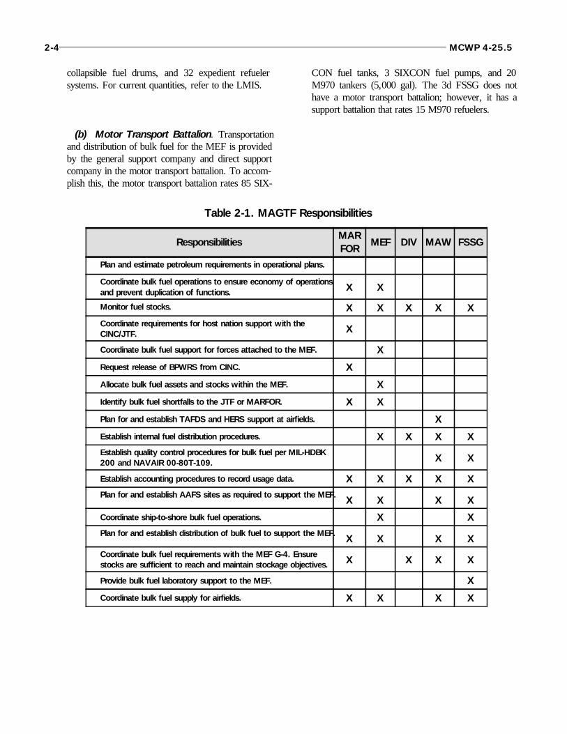
Table 2-1. MAGTF Responsibilities
ResponsibilitiesMARFOR
MEF DIV MAW FSSG
Plan and estimate petroleum requirements in operational plans.
Coordinate bulk fuel operations to ensure economy of operationsand prevent duplication of functions. X X
Monitor fuel stocks. X X X X XCoordinate requirements for host nation support with theCINC/JTF. X
Coordinate bulk fuel support for forces attached to the MEF. X
Request release of BPWRS from CINC. X
Allocate bulk fuel assets and stocks within the MEF. X
Identify bulk fuel shortfalls to the JTF or MARFOR. X X
Plan for and establish TAFDS and HERS support at airfields. X
Establish internal fuel distribution procedures. X X X XEstablish quality control procedures for bulk fuel per MIL-HDBK200 and NAVAIR 00-80T-109. X X
Establish accounting procedures to record usage data. X X X X XPlan for and establish AAFS sites as required to support the MEF. X X X X
Coordinate ship-to-shore bulk fuel operations. X XPlan for and establish distribution of bulk fuel to support the MEF. X X X XCoordinate bulk fuel requirements with the MEF G-4. Ensurestocks are sufficient to reach and maintain stockage objectives. X X X X
Provide bulk fuel laboratory support to the MEF. X
Coordinate bulk fuel supply for airfields. X X X X

3001. Amphibious Assault FuelSystem
The Amphibious Assault Fuel System (AAFS) (USMCTAMCN B0685) is the largest of the TFS. Consisting ofmany self-contained units, the AAFS is used to receive,store, transfer, and dispense all types of fuel. The AAFSsupplies bulk fuel to all elements of a MAGTF includingdistribution by hoseline to airfields. The system can re-ceive fuel from offshore vessels, railcars, tank trucks, bulkstorage tanks, pipeline/hoseline, and drums. Fuel is storedand can be transferred to another storage site or dispensedto individual containers, vehicles, tank trucks, and otherfuel systems.
a. Composition. Six assemblies make up the AAFS:
Beach unloading assembly.
Drum unloading assembly.
Two booster station assemblies.
Two adapting assemblies.
Dispensing assembly.
Five tank farm assemblies.
Each AAFS has one beach unloading assembly used forreceiving fuel during ship-to-shore operations. Twobooster station assemblies in each AAFS are used when
the distance between storage sites is greater than thepumping distance. The AAFS storage capacity comesfrom the five tank farms. One drum unloading assembly ineach AAFS provides the capability to defuel 55-gallondrums. One dispensing assembly in each AAFS providesthe capability to dispense fuel. The AAFS has two adapt-ing assemblies to make the system compatible with com-mercial and other Services’ fuel systems. Versatility is animportant part of the AAFS. It can be deployed as a wholeor tailored to meet mission requirements. However, eachAAFS may contain only one type of fuel.
b. Capacity. The AAFS storage capacity is 600,000gallons made up from its five tank farms. The AAFS hasapproximately 3.5 miles of 6-inch hose and uses ten 600-gallons per minute (gpm) pumps. Using quick-connect,cam-lock fittings, the AAFS can be assembled withouttools and is compatible with the other Marine Corps TFSs.
3002. Tactical Airfield Fuel Dispensing System
Similar in design to the AAFS tank farm, the Tactical Air-field Fuel Dispensing System (TAFDS) (USMC TAMCNB0675) is used to provide bulk fuel support at MarineCorps expeditionary airfields. The primary purpose of theTAFDS is aircraft refueling. This system is air-transportable and versatile and can be quickly assembled.Compatible with other Marine Corps TFSs, the TAFDS
Chapter 3
Tactical Fuel Systems
Marine Corps bulk fuel equipment has to meet a wide spectrum of requirementsfrom ship-to-shore operations to aircraft refueling. To meet these requirements, theMarine Corps has developed a family of tactical fuel systems (TFS). Each system isdesigned and configured specifically to support a unique mission using similarcomponents. The ability to alter fundamental system configurations and inter-changeability of components allows the creation of limitless combinations of tai-lored systems to meet mission requirements.
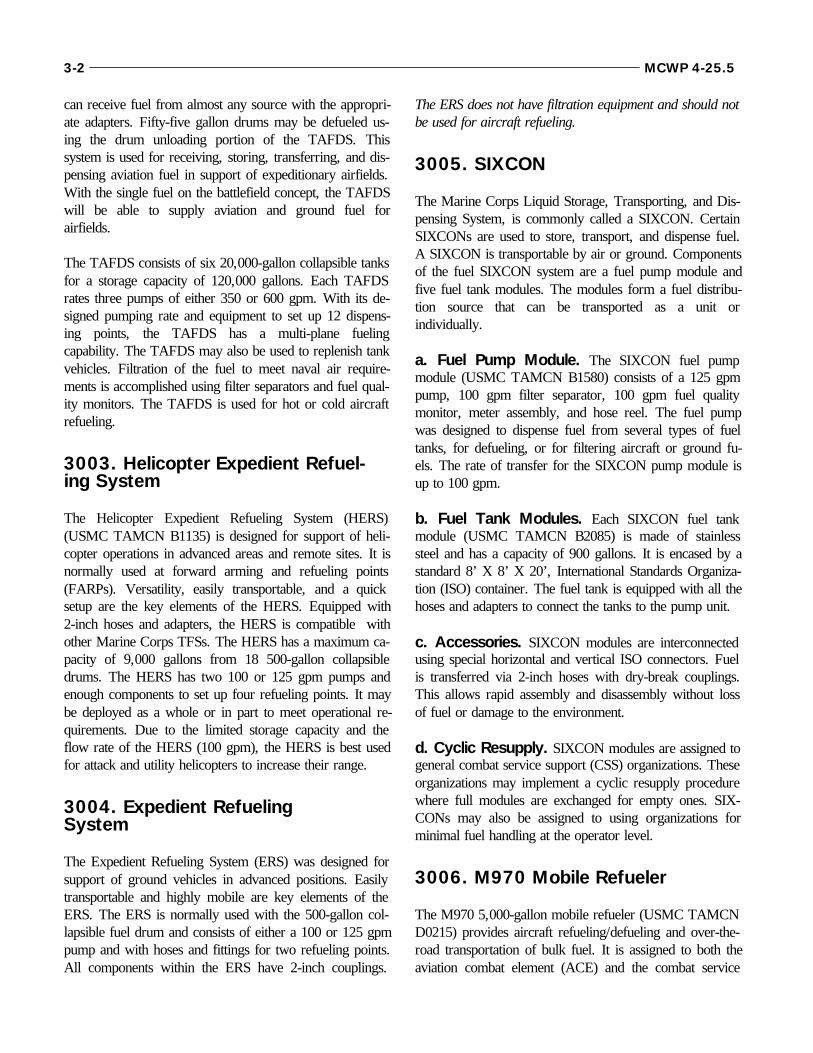
can receive fuel from almost any source with the appropri-ate adapters. Fifty-five gallon drums may be defueled us-ing the drum unloading portion of the TAFDS. Thissystem is used for receiving, storing, transferring, and dis-pensing aviation fuel in support of expeditionary airfields.With the single fuel on the battlefield concept, the TAFDSwill be able to supply aviation and ground fuel forairfields.
The TAFDS consists of six 20,000-gallon collapsible tanksfor a storage capacity of 120,000 gallons. Each TAFDSrates three pumps of either 350 or 600 gpm. With its de-signed pumping rate and equipment to set up 12 dispens-ing points, the TAFDS has a multi-plane fuelingcapability. The TAFDS may also be used to replenish tankvehicles. Filtration of the fuel to meet naval air require-ments is accomplished using filter separators and fuel qual-ity monitors. The TAFDS is used for hot or cold aircraftrefueling.
3003. Helicopter Expedient Refuel-ing System
The Helicopter Expedient Refueling System (HERS)(USMC TAMCN B1135) is designed for support of heli-copter operations in advanced areas and remote sites. It isnormally used at forward arming and refueling points(FARPs). Versatility, easily transportable, and a quicksetup are the key elements of the HERS. Equipped with2-inch hoses and adapters, the HERS is compatible withother Marine Corps TFSs. The HERS has a maximum ca-pacity of 9,000 gallons from 18 500-gallon collapsibledrums. The HERS has two 100 or 125 gpm pumps andenough components to set up four refueling points. It maybe deployed as a whole or in part to meet operational re-quirements. Due to the limited storage capacity and theflow rate of the HERS (100 gpm), the HERS is best usedfor attack and utility helicopters to increase their range.
3004. Expedient Refueling System
The Expedient Refueling System (ERS) was designed forsupport of ground vehicles in advanced positions. Easilytransportable and highly mobile are key elements of theERS. The ERS is normally used with the 500-gallon col-lapsible fuel drum and consists of either a 100 or 125 gpmpump and with hoses and fittings for two refueling points.All components within the ERS have 2-inch couplings.
The ERS does not have filtration equipment and should notbe used for aircraft refueling.
3005. SIXCON
The Marine Corps Liquid Storage, Transporting, and Dis-pensing System, is commonly called a SIXCON. CertainSIXCONs are used to store, transport, and dispense fuel.A SIXCON is transportable by air or ground. Componentsof the fuel SIXCON system are a fuel pump module andfive fuel tank modules. The modules form a fuel distribu-tion source that can be transported as a unit orindividually.
a. Fuel Pump Module. The SIXCON fuel pumpmodule (USMC TAMCN B1580) consists of a 125 gpmpump, 100 gpm filter separator, 100 gpm fuel qualitymonitor, meter assembly, and hose reel. The fuel pumpwas designed to dispense fuel from several types of fueltanks, for defueling, or for filtering aircraft or ground fu-els. The rate of transfer for the SIXCON pump module isup to 100 gpm.
b. Fuel Tank Modules. Each SIXCON fuel tankmodule (USMC TAMCN B2085) is made of stainlesssteel and has a capacity of 900 gallons. It is encased by astandard 8’ X 8’ X 20’, International Standards Organiza-tion (ISO) container. The fuel tank is equipped with all thehoses and adapters to connect the tanks to the pump unit.
c. Accessories. SIXCON modules are interconnectedusing special horizontal and vertical ISO connectors. Fuelis transferred via 2-inch hoses with dry-break couplings.This allows rapid assembly and disassembly without lossof fuel or damage to the environment.
d. Cyclic Resupply. SIXCON modules are assigned togeneral combat service support (CSS) organizations. Theseorganizations may implement a cyclic resupply procedurewhere full modules are exchanged for empty ones. SIX-CONs may also be assigned to using organizations forminimal fuel handling at the operator level.
3006. M970 Mobile Refueler
The M970 5,000-gallon mobile refueler (USMC TAMCND0215) provides aircraft refueling/defueling and over-the-road transportation of bulk fuel. It is assigned to both theaviation combat element (ACE) and the combat service
3-2 MCWP 4-25.5
support element (CSSE). Within the ACE, the M970 isorganic to the MWSS and is used primarily to refuel air-craft. Within the CSSE, the M970 is organic to the motortransport battalion and is assigned to CSSE motor trans-port and/or engineer detachments. The CSSE uses theM970 to transport bulk fuel between storage sites or di-rectly to the customer.
3007. Tactical PetroleumLaboratory-Medium
The Tactical Petroleum Laboratory-Medium (TPLM)(TAMCN B0695) provides the essential testing compo-nents integrated into an ISO container to monitor the criti-cal physical and chemical characteristics of aviation andground fuels. JP-4, JP-5, JP-8, diesel, and their commer-cial grade equivalents can be tested for composition andquality against minimum standards as specified inMIL-HDBK-200, Quality Surveillance Handbook forFuel, Lubricants and Related Products. The TPLM canalso test captured fuels.
3008. USMC Aircraft Bulk Fuel Handling Systems
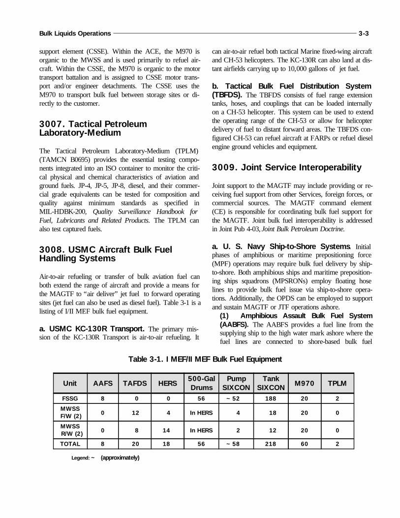
Air-to-air refueling or transfer of bulk aviation fuel canboth extend the range of aircraft and provide a means forthe MAGTF to “air deliver” jet fuel to forward operatingsites (jet fuel can also be used as diesel fuel). Table 3-1 is alisting of I/II MEF bulk fuel equipment.
a. USMC KC-130R Transport. The primary mis-sion of the KC-130R Transport is air-to-air refueling. It
can air-to-air refuel both tactical Marine fixed-wing aircraftand CH-53 helicopters. The KC-130R can also land at dis-tant airfields carrying up to 10,000 gallons of jet fuel.
b. Tactical Bulk Fuel Distribution System(TBFDS). The TBFDS consists of fuel range extensiontanks, hoses, and couplings that can be loaded internallyon a CH-53 helicopter. This system can be used to extendthe operating range of the CH-53 or allow for helicopterdelivery of fuel to distant forward areas. The TBFDS con-figured CH-53 can refuel aircraft at FARPs or refuel dieselengine ground vehicles and equipment.
3009. Joint Service Interoperability
Joint support to the MAGTF may include providing or re-ceiving fuel support from other Services, foreign forces, orcommercial sources. The MAGTF command element(CE) is responsible for coordinating bulk fuel support forthe MAGTF. Joint bulk fuel interoperability is addressedin Joint Pub 4-03, Joint Bulk Petroleum Doctrine.
a. U. S. Navy Ship-to-Shore Systems. Initialphases of amphibious or maritime prepositioning force(MPF) operations may require bulk fuel delivery by ship-to-shore. Both amphibious ships and maritime preposition-ing ships squadrons (MPSRONs) employ floating hoselines to provide bulk fuel issue via ship-to-shore opera-tions. Additionally, the OPDS can be employed to supportand sustain MAGTF or JTF operations ashore.
(1) Amphibious Assault Bulk Fuel System(AABFS). The AABFS provides a fuel line from thesupplying ship to the high water mark ashore where thefuel lines are connected to shore-based bulk fuel
Bulk Liquids Operations 3-3
Table 3-1. I MEF/II MEF Bulk Fuel Equipment
Unit AAFS TAFDS HERS500-GalDrums
PumpSIXCON
TankSIXCON M970 TPLM
FSSG 8 0 0 56 ~52 188 20 2
MWSS F/W (2) 0 12 4 In HERS 4 18 20 0
MWSS R/W (2) 0 8 14 In HERS 2 12 20 0
TOTAL 8 20 18 56 ~58 218 60 2
Legend: ~ (approximately)

systems of the landing force. The AABFS consists ofbuoyant, 6-inch (diameter) reinforced rubber hose linesup to 10,000 feet in length. Two or more buoyant linescan be connected to achieve greater distances betweenthe ship and the shoreline. However, they require float-ing booster stations to do fuel transfer when the distanceis more than 5,000 feet. Buoyant hose systems are em-ployed to support the initial phases of amphibious land-ings. An AABFS can be installed in 4 to 6 hours underfavorable surf conditions.
(2) Offshore Petroleum Discharge System(OPDS). The OPDS is designed to discharge pe-troleum products to USMC AAFS, U.S. Armytactical petroleum terminals (TPTs), or U.S.Army inland petroleum distribution system(IPDS) pipelines. The OPDS can be installed upto 4 statute miles off-shore and supports ship-to-shore fuel replenishment rates of up to 1.2 milliongallons per day (based on a 20-hour operating day). The OPDS can produce delivery rates of1,000 gpm.
If the ship stand-off distance is less than 2 statutemiles, dual lines can be used which results infaster product transfer.
The OPDS includes the initial fuel tanker (ship)which provides the initial delivery of fuel (up to15 million gallons) and the mooring apparatus foritself and follow-on tankers. The OPDS employseither a 4 point moor or a single anchor legmooring (SALM) with surface buoy to allow theship to moor and “weather vane” in the prevailingwinds in a 360-degree arc.
The system is installed by Military Sealift Com-mand civilian crews with the assistance of navalsupport personnel. Besides underwater divers andsupport personnel from an amphibious construc-tion battalion, the system requires side-loadablewarping tugs and/or powered or non-poweredcauseway sections to conduct the installation.
b. U.S. Army Petroleum Systems. Theater sup-port may be provided from U.S. Army fuel sources. Fuelsupport, which includes interface with Marine CorpsTFSs, must be planned and coordinated in advance. Theselection of specific systems depends on the projected re-quirements. The U.S. Army theater fuel manager coordi-nates fuel delivery requirements. When operating with theU.S. Air Force, the U.S. Army can airdrop fuel in quanti-ties up to 10,000 gallons in support of operating forces.Fuel support equipment employed may include TPTs,IPDS, or line haul vehicles.
c. U.S. Air Force Air-based Petroleum Sys-tems. Refueler aircraft and aircraft equipped with aerialbulk fuel delivery systems (ABFDS) may be required tosupport MAGTF operations. Support capability rangesfrom air delivery of packaged fuel (500-gallon collapsibledrums) to bulk fuel pumped from transport aircraft or air-craft internal tanks. See table 3-2. Wet-wingrefueling/defueling methods may be prescribed for specialmission support operations. These methods may rangefrom the transfer of jet fuel from a delivery aircraft to re-ceiving tactical storage systems or into a receiving aircraft.
3-4 MCWP 4-25.5
Type Aircraft500-Gal Drum Delivery Model
And Gallon CapacityWet-Wing Delivery Model
And Gallon CapacityC-130 5,000 4,400
C-141 9,000 12,500
C-5A/B 27,000 29,000
Table 3-2. Aircraft Fuel Delivery Capability
Bulk Liquids Operations 3-5
(reverse blank)
4001. Planning Requirements for BulkFuel
Planning for bulk fuel support can be a complex and chal-lenging task. Time, space, distances, terrain, resources,and the operating environment are all planning factors thathave to be considered. There are six major elements ofbulk fuel planning—requirements, sourcing and procure-ment, transportation, storage, distribution, and equipment.
a. Requirements. Determining bulk fuel requirementsis one of the most important planning elements for bulkfuel support. Requirements have to be determined beforeany of the other elements can be effectively considered.Requirements will be the main factor in deciding equip-ment, personnel, and stockage objectives.
b. Sourcing and Procurement. Determining thesource and provider of bulk fuel stocks to the MAGTF orMarine forces varies greatly depending on the situation.Before deploying, the planner needs to determine fuelsources and establish procurement procedures.
c. Transportation. Planning for bulk fueltransportation involves movement of fuel from the fuelsource to the Marine Corps bulk fuel sites. This is usuallya wholesale function that will be provided or arranged bythe joint petroleum office. Transportation methods includeships, railcars, tank trucks, pipeline, and aircraft.
d. Storage. Planning for bulk fuel storage requires aconsideration of requirements, stockage objectives, and thefrequency of resupply. The joint commander prescribesbulk fuel supply levels for the theater in days of supply(DOS). Marine component and/or MAGTF commandersprescribe supply levels for Marine forces based on require-ments and equipment availability. When operating in ajoint environment, the Marine Corps planners must planfor the supply levels of all organizations that it may besupporting.
e. Distribution. Distribution consists of transportingfuel from the bulk storage site to the using units. Distribu-tion can also be called the retail end of the transportationsystem.
Chapter 4
Bulk Fuel Planning
Normally, bulk fuel capabilities are spread throughout the MAGTF. This is espe-cially true of bulk fuel distribution capabilities. But with the smaller forces of today,there is often a benefit to consolidating the bulk fuel assets. For example, if a mobilerefueler was controlled by a central organization, it could be used to support severalunits and would be used to the maximum extent possible. This would not be true ifeach unit had its own mobile refueler. The MAGTF has also provided central or-ganizations—the ACE and the CSSE—for its bulk storage requirements.
To be effective, the overall bulk fuel effort needs to be planned and coordinated atthe MAGTF level as early as possible. The planning and coordination effort mustcontinue throughout the operation. Due to the significant bulk fuel capabilitieswithin the Marine Corps, Marine Corps requirements for bulk fuel support can bemet in most situations if bulk fuel capabilities are properly used.

f. Equipment. The bulk fuel equipment required to sup-port the mission is based on the other five elements forbulk fuel planning—requirements, sourcing and procure-ment, transportation, storage and distribution. Planning forbulk fuel equipment must include both stationary and mo-bile bulk fuel equipment.
4002. Planning Considerations
The bulk fuel supply system must be designed accordingto the mission, terrain, and climate. The planner must con-sider the following:
The mission and force to be supported.
The fuel requirements of that force.
The capability of installations and/or unit (to in-clude host nation) to provide the required support.
The time to construct an operational bulk fuelsystem.
The requirements for bulk fuel storage facilities,offshore unloading facilities, pipeline/hoseline,and distribution points.
The availability of bulk fuel units and other unitsneeded to construct, install, operate, and maintainthe bulk fuel system.
The terrain, since this impacts both the abilityto install the bulk fuel system and fuel usagefactors.
4003. Planning Categories
Bulk fuel planning falls into two basic categories—logisti-cal and operational.
a. Logistical Planning. Logistical planning involvesdetermining specific fuel requirements and distributionplans based on factors such as fuel consuming equipment,mission, terrain, and climate. Logistical planning is startedwell in advance of actual operations at the JTF, Marinecomponent, and MAGTF level. The primary purpose oflogistical planning is to ensure that fuel products, equip-ment, bulk fuel operating units, and host nation or com-mercial support will be available when needed.
b. Operational Planning. Operational planning in-cludes planning to reach the required capacity of the bulk
fuel supply system and to maintain the required capacityfor meeting mission requirements. This planning is carriedout before and during operations. Operational planning hasto be flexible and allow for changes due to tactical devel-opments, losses in fuel stocks and equipment, and otherfactors that may keep the system from operating asplanned.
4004. Planning for Joint Bulk Fuel Operations
The supported CINC and/or the joint commander is re-sponsible for the overall planning of bulk fuel logisticalsupport. The unified or joint command plan is the basis forall subordinate bulk fuel support plans. This plan estab-lishes concepts, objectives, assigns missions, and allocatesavailable resources. Operation plans submitted to the jointstaff will include a petroleum appendix to the logistics an-nex in the format prescribed in Joint Pub 5-03.2, Joint Op-eration Planning and Execution System (JOPES), VolumeII. See appendix A. The Service components develop abulk fuel support concept based on the tactical plan. Oncethe concept is approved by the joint commander, the Serv-ice components then prepare the implementing bulk fuelsupport plan. During operations, the joint staff and theService bulk fuel planners revise the basic plans as re-quired to support the mission.
a. Army Petroleum Group. Normally, the Army pe-troleum group or designated dominant Service is responsi-ble for theater bulk fuel planning and the theater inlandpetroleum distribution plan. This planning is done in con-cert with the component Services’ bulk fuel plans. Thetheater inland petroleum distribution plan is prepared andpublished as an annex to the theater logistic support plan.
b. Compatibility. During joint operations, the compati-bility between the Services’ bulk fuel systems is a key fac-tor. Compatibility must be addressed during the planningcycle with emphasis on the following interfaces:
Ship-to-shore offload facilities.
Aircraft fuel dispensing systems.
Land-based distribution systems and mobile re-fueling equipment.
4005. Marine Corps Bulk Fuel Planning
4-2 MCWP 4-25.5

The Marine Corps must maintain the ability to deploy rap-idly to a variety of environments and tactical situations.Once in place, our forces must be able to operate with afull spectrum of bulk fuel support. A key factor to success-ful bulk fuel planning is early coordination between thefuel planners and the operators. To develop an effectivefuel plan, the planners must have a good understanding ofthe concept of operations and the tactical equipment beingused.
a. Determine Requirements. The first step is tocollect data so the planner can get an estimate of the fuelrequirements for Marine forces. While this is not intendedto be an exact figure, it does need to be as accurate as pos-sible because of the large impact fuel requirements have onother planning elements. It is often said that it is better tohave too much fuel than to run out. While this is true, itcan be taken to the extreme.
(1) Automated Systems. Marine Corps fuel plan-ners have become dependent on automated systems forcomputing fuel requirements. While these systems savetime and man-hours, they usually compute fuel require-ments that are higher than operating forces actuallyneed. Using the higher requirements during planningwill result in having too much fuel on hand, but moreimportantly, it could result in the MAGTF taking toomuch bulk fuel equipment and occupying embarkationspace that could be used for something else. Duringplanning, the best method of determining fuel require-ments will be to use equipment densities and consump-tion rates. Consumption is affected by combat intensity,hours of operation, mission, quantity of equipment, andtheater of operation. It is important that the proper ef-fort be placed on bulk fuel requirement planning to en-sure the best allocation of assets.
(2) Time Phasing. An equally important function ofbulk fuel requirements identification is time phasing.Bulk fuel requirements must be time-phased to coordi-nate transportation, storage, and distribution. Time-phased requirements begin with a determination of dailyrequirements in the objective area. This includes dailydemand, storage capacity, throughput capability, andtime delay from initial request until delivery.
(3) Methods of Computing Fuel Requirements.All MAGTF elements are responsible for estimatingtheir fuel requirements and submitting them in a timelymanner. Fuel requirements should be computed at the
staff level based on historical data, equipment density,time, and operational tempo. Fuel planners need to pro-vide specific guidance to the units on the procedures tobe followed. The guidance should provide dataconcerning hours-per-day, resupply times, DOS onhand, and operational tempo. To prohibit units from us-ing any “fudge factor”, planners need to keep in mindthat there is a point where too much fuel is not eco-nomical in terms of equipment and personnel. The bulkfuel staff officers will review requirements submissionsfor accuracy.
Current planning factors for ground fuels are based onthe consumption rates in the item data file (IDF) of thelogistics management information system (LMIS).Consumption rates are calculated for each item ofequipment by multiplying the gallons-per-hour usagerate by the hours-per-day rate. This is the main reasonfuel requirements are often overestimated.
The IDF lists most equipment as operating 20 hours perday. This method does not distinguish between equip-ment in combat units and equipment in support units.Nor does it allow for variation in the operational tempoof the unit or in the method of employing the equip-ment. While the IDF can usually be used for gallons-per-hour, the hours-per-day rate for various types ofequipment should be determined by the operationalplanners.
Spreadsheets have been developed for ground equip-ment that allow the planner to input the hour-per-dayrate for each item of equipment and the spreadsheetcomputes a daily requirement. These spreadsheets areavailable from the MEF bulk liquids sections or theMarine Corps Detachment, Fort Lee, Virginia.
Aviation fuels are computed using aircraft characteris-tic manuals. These manuals are more accurate than theIDF and historically aviation fuel requirements are notas overstated as ground fuel requirements. This methodtakes into account the operational tempo, sortie rates,sortie lengths, and fuel rates for each type of aircraft. It is also recommended that aviation fuel
requirements be computed at the staff level based on theaircraft density and the operational tempo providedfrom the G-3/S-3. Fuel planners need to provide spe-cific guidance to the units on the procedures to be
Bulk Liquids Operations 4-3
followed. The bulk fuel staff officers will review re-quirements submissions for accuracy.
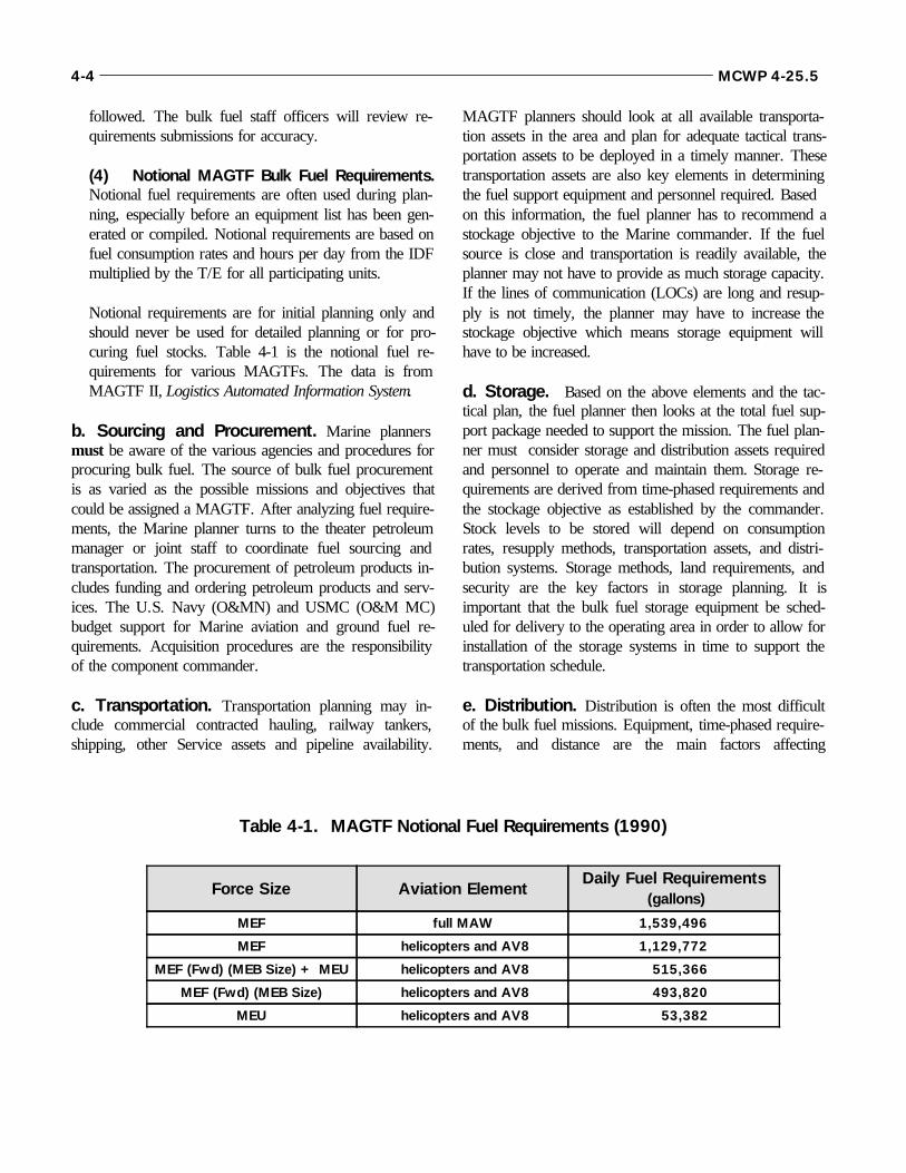
(4) Notional MAGTF Bulk Fuel Requirements.Notional fuel requirements are often used during plan-ning, especially before an equipment list has been gen-erated or compiled. Notional requirements are based onfuel consumption rates and hours per day from the IDFmultiplied by the T/E for all participating units.
Notional requirements are for initial planning only andshould never be used for detailed planning or for pro-curing fuel stocks. Table 4-1 is the notional fuel re-quirements for various MAGTFs. The data is fromMAGTF II, Logistics Automated Information System.
b. Sourcing and Procurement. Marine plannersmust be aware of the various agencies and procedures forprocuring bulk fuel. The source of bulk fuel procurementis as varied as the possible missions and objectives thatcould be assigned a MAGTF. After analyzing fuel require-ments, the Marine planner turns to the theater petroleummanager or joint staff to coordinate fuel sourcing andtransportation. The procurement of petroleum products in-cludes funding and ordering petroleum products and serv-ices. The U.S. Navy (O&MN) and USMC (O&M MC)budget support for Marine aviation and ground fuel re-quirements. Acquisition procedures are the responsibilityof the component commander.
c. Transportation. Transportation planning may in-clude commercial contracted hauling, railway tankers,shipping, other Service assets and pipeline availability.
MAGTF planners should look at all available transporta-tion assets in the area and plan for adequate tactical trans-portation assets to be deployed in a timely manner. Thesetransportation assets are also key elements in determiningthe fuel support equipment and personnel required. Basedon this information, the fuel planner has to recommend astockage objective to the Marine commander. If the fuelsource is close and transportation is readily available, theplanner may not have to provide as much storage capacity.If the lines of communication (LOCs) are long and resup-ply is not timely, the planner may have to increase thestockage objective which means storage equipment willhave to be increased.
d. Storage. Based on the above elements and the tac-tical plan, the fuel planner then looks at the total fuel sup-port package needed to support the mission. The fuel plan-ner must consider storage and distribution assets requiredand personnel to operate and maintain them. Storage re-quirements are derived from time-phased requirements andthe stockage objective as established by the commander.Stock levels to be stored will depend on consumptionrates, resupply methods, transportation assets, and distri-bution systems. Storage methods, land requirements, andsecurity are the key factors in storage planning. It isimportant that the bulk fuel storage equipment be sched-uled for delivery to the operating area in order to allow forinstallation of the storage systems in time to support thetransportation schedule.
e. Distribution. Distribution is often the most difficultof the bulk fuel missions. Equipment, time-phased require-ments, and distance are the main factors affecting
4-4 MCWP 4-25.5
Force Size Aviation ElementDaily Fuel Requirements
(gallons)
MEF full MAW 1,539,496
MEF helicopters and AV8 1,129,772
MEF (Fwd) (MEB Size) + MEU helicopters and AV8 515,366
MEF (Fwd) (MEB Size) helicopters and AV8 493,820
MEU helicopters and AV8 53,382
Table 4-1. MAGTF Notional Fuel Requirements (1990)
distribution. Distribution problems will normally becomemore complex the longer the operation, the greater theconsumption rates, and the farther inland the MAGTFgoes. Resupply concepts of unit versus supply point distri-bution will also affect the type and amount of resourcesneeded to support bulk fuel distribution to the MAGTF.
4006. War Reserve Requirements andStocks
a. Bulk Petroleum War Reserve Requirements(BPWRR). To ensure the supply of petroleum productsin the initial phases of a contingency, the Unified Com-mands and the Services develop requirements to sizepetroleum war reserve stocks properly. The BPWRR isbased on the need to support specific contingency opera-tions until normal LOCs are established. The Joint staffdevelops guidelines, approved by the Office of the Secre-tary of Defense (OSD), on DOS and appropriate assump-tions on secure sources of resupply. These guidelines areprovided to the Services and CINCs and serve as the basisfor determining requirements. Using these guidelines, theServices develop and apply structured, auditable methodsof computing BPWRR for each theater/com- mandOPLAN. Bulk fuel requirements for the MAGTF arefilled from a combination of sources such as the CINCjoint petroleum offices, sub-area petroleum offices, defensefuel regions, host nation, Navy Petroleum Office, andlanding forces operational reserve material.
b. Bulk Petroleum War Reserve Stocks(BPWRS). BPWRS is the onhand product designated tosatisfy BPWRR. This stockage is in addition to the pri-mary operating stock (POS) for each location. Command-ers of unified commands are authorized to release orreallocate BPWRS in emergency situations. BPWRS areoften stored in theater and are managed by the appropriateCINC JPO/SAPO.
c. Computation of Bulk Fuel Requirements.The MEF G-4 calculates bulk fuel BPWRR based on air-craft and equipment density and the concept of logisticssupport, to support each operation/contingency plan. Thebulk fuel requirements are computed and time-phased bylocation and type product.
(1) Aviation Fuel. Consumption factors used in therequirements determination process for aviation fuel canbe found in NAVAIR NOTICE C10340 or C13100.
(2) Ground Fuel. Ground fuel requirements are com-puted using MAGTF II based on the MEF’s equipmentdensity in the appropriate OPLAN.
d. MEF BPWRR. The Joint Staff establishes the timeperiod that Marine forces will initially be committed foreach OPLAN. The MEF computes BPWRR based on thetime period, contingency location, and type of product re-quired. The Joint Staff also establishes prepositioning ob-jectives for regions and areas worldwide in the form ofcombat days of petroleum supply to be maintained in ac-cordance with DOD Directive 4220.7. These objectivesconsider such factors as wartime tanker sailing times, in-theater distribution times, attrition factors, and appropriatesafety levels. As a result, the amount of bulk fuel BPWRR(DOS) that the MEF can register varies depending on thetheater in which the MEF is operating. The MEF will usu-ally have less than 60 DOS of bulk fuel as accompanyingsupplies or BPWRS, and resupply will begin at a date ear-lier than D+60.
(1) DD Form 1887. The BPWRR not stored byMarine forces (LFORM) will be reported to DFSC as aterminal prepositioning requirement on DD Form1887, Prepositioned War Reserve Requirements forTerminal Storage (DOD 4140.25-M). The DD Form1887 or its equivalent must be coordinated with the na-val component or with the CINC JPO if the Marinesare a component command. This coordination is re-quired prior to submission of the completed DD Form1887. If Marine forces are operating under a navalcomponent, the naval component will submit the com-pleted DD Form 1887 to DFSC via NAVPET. If oper-ating as a Marine component, the commander willsubmit the completed DD Form 1887 to DFSC viaNAVPET. DFSC and the CINC JPOs announce whenthe DD Form 1887 submissions are due. Normally theinput to the JPOs for coordination is due on 1 Octoberand the input to NAVPET is due 1 November of eachyear.
(2) Consolidated Defense Fuel Supply Points.The DFSC consolidates Military Service BPWRRfor storage at defense fuel supply points (DFSP) and
Bulk Liquids Operations 4-5
assigns maximum and minimum storage levels in theinventory management plan (IMP). In consonance withapproved stock fund operating plans and budgets, it ispossible that the entire amount of BPWRS that theMEF is authorized in a particular theater may not besourced. If the Marine forces have a bulk fuel shortfall,the Marine component commander will notify the ap-propriate CINC JPO. The document that identifies theamount of BPWRS that are allocated to the MEF is theDFSC IMP. The IMP contains the MEF BPWRR bylocation and identifies the BPWRS that are sourced tomeet that requirement. The Marine component G-4 andthe MEF bulk liquids section maintain current copies ofthe IMP.
(3) Prepositioned BPWRS. DFSC will attempt topreposition BPWRS at the terminal location nominatedby the Military Service. Where storage or operationalconditions are limited, DFSC will locate stocks, at themost appropriate alternate terminal, following coordina-tion with the unified command and the requiring Mili-tary Service. Malpositioned stocks shall be countedagainst the total BPWRR. However, these stocks maynot be counted as days of support available at the pointof planned use during assessment of operation planscapability.
4-6 MCWP 4-25.5

5001. Developed Theater
In a developed theater, an existing bulk fuel distributionsystem is usually available to help support Marine Corpsforces. The existing system helps offset the requirementsfor Marine Corps TFSs. A developed theater usually con-sists of tanker unloading facilities, terminals, pipelines,pump stations, dispensing facilities, and rail tank carfacilities.
Actual procedures for accomplishing the delivery of bulkfuel to the user will vary between theaters. These facilities will normally be operated by civilian personnel or thetheater Army. However, Marine Corps bulk fuel units could be tasked with operating the facilities, particularlyduring the early phases of operations before the theaterArmy has all its assigned forces.
a. Pipeline System. In a developed theater, the pipe-line system usually extends into the Army corps rear withhoseline extensions into Army corps storage sites and Ma-rine Corps force combat service support areas (FCSSAs)and airfields. When practical, branch lines from the pipe-line are used to supply major users such as Marine CorpsCSSDs and MWSSs. If required (and if available), thepipeline/hoseline system is supplemented by military tanktrucks and commercial vehicles. These bulk transports canbe used to move bulk fuel in the supply times. Also, the
stockage objective that Marine theater zone and up to and including the Army corps rear area.
b. Theater Stockage Objectives. In a developedtheater, most of the theater stockage objectives are usuallyheld in fixed facility storage tanks. This reduces the quan-tity of bulk fuel that the Marine Corps would need tostore in tactical bulk fuel systems. Theater stockage objec-tives will vary between theaters depending on resupplytimes. The stockage objective that Marine forces need tohold in tactical fuel systems will depend on resupply timesfrom theater storage and the daily fuel requirement. Gener-ally, MAGTF TFSs should be capable of storing a mini-mum of 5 DOS in a developed theater. This will allow forcontinuous fuel support to Marine forces if fuel resupplyfrom theater sources is delayed.
5002. Undeveloped Theater
Providing fuel support in an undeveloped theater pre- sentsmany problems not faced in a developed area. TFSs haveto be brought into the area and mooring facilities, storagefacilities, pipeline, and/or hoselines have to be installed.During the early stages of an operation, forces have to relyon their organic equipment and personnel. As the opera-tion progresses, additional equip- ment and personnel arebrought in to expand the fuel system. A TFS capable ofsupporting the mission is developed in the area when
Chapter 5
Bulk Fuel Theater Operations
In theater operations, the MAGTF commander may be part of a developed or unde-veloped theater. Bulk fuel support concerns and requirements are addressed accord-ing to the development stage of a theater. The three main objectives of bulk fuelsupport are supplying fuel when needed, distributing fuel where needed, and provid-ing fuel resupply on time. When the MAGTF is involved in a sustained operationashore, bulk fuel operations are deployed in three phases: development, lodgment,and buildup.
practical. Initial fuel storage facilities should be expandedwhen possible so floating storage (tankers or barges) hold-ing reserve fuel for shore units may be released.
Any available commercial or host nation support will beconsidered for use as part of the bulk fuel system. Use ofthese systems and their bulk fuel products should be ob-tained through DFSC contracts, local purchase procedures,or through host nation support agreements.
a. Minimum Bulk Fuel Stockage Objective. Theminimum bulk fuel stockage objective for the undevelopedtheater is 15 DOS. This includes bulk fuel stored in tacticalequipment and off-shore shipping or floating dumps. Fuelis distributed from beach storage by hoseline, tank vehi-cles, helicopters, and any other means available. As thefuel system is developed, it will consist of hoselines andcollapsible storage tanks. The primary method of receivingbulk fuel in the undeveloped theater will be ship-to-shoreoperations using Navy shipping with the AABFS or theOPDS.
b. Tactical Hoseline. Large users such as tactical air-fields are supplied by tactical hoseline when possible.The tactical hoseline and/or pipeline will extend as far for-ward as possible, usually into the Army corps rear area, toreduce mobile transport requirements. Although hoselinesare the most rapid and easily deployed system, a more per-manent system is normally installed if the system muststay in place for long periods. When possible, the reararea communications zone, corps support, and FSSA areaswill be established. In the early stages, the theater mayonly consist of a JTF support area, MEF forward areawith CSSDs, or Army division support area, and later anArmy corps support area. The rear area communicationszone may never be formed de-pending on the duration ofthe operation.
c. Air Lines of Communications. In the earlystages of an undeveloped theater, there is often a re- quire-ment to support forces with air lines of communications(ALOC). The Air Force Air Mobility Command providesthis support with C-130, C-141, and C5A aircraft. Re-quirements for ALOC support are coordinated throughchannels established in the OPLANs. The following typesof aerial bulk fuel support are available from the Air Mo-bility Command (AMC):
(1) Packaged Products. The 500-gallon collapsibledrums and 55-gallon drums may be internally loaded in
cargo aircraft for delivery to airfields near the units be- ingsupported.
(2) Airdrop. When suitable aircraft loading and unload-ing areas are not available, fuel may be airdropped or de-livered by low altitude parachute extraction systems(LAPES).
(3) Aerial Bulk Fuel Delivery System (ABFDS) . TheAir Force has aircraft specially equipped with internal col-lapsible tanks and a pump for deliveries of bulk fuels intoareas where suitable landing sites are available.
(4) Wet Wing Refueling. The C-130, C-141, andC5A aircraft have internal pumps for defueling. UsingMarine Corps or Army ground equipment (hoses and noz-zles), these aircraft can deliver aviation fuel into MarineCorps or Army storage containers located at suitable land-ing areas. Refer to table 3-2, page 3-5.
5003. Phases of Bulk FuelOperations
During sustained operations ashore, tactical bulk fuelequipment must be deployed to provide support to theMAGTF. To best support the MAGTF, bulk fuel opera-tions should be conducted in three phases: development,lodgment, and build-up.
a. Development. Due to the high consumption andlimited bulk fuel capabilities, the development phase is of-ten the most critical phase of bulk fuel operations. Thecommander and staff need to look closely at the fuel rangeof the vehicles going ashore, the time-phased resupplyavailable, and the equipment available to support theMAGTF during this phase. The development phase maybe initiated as an airborne, airmobile, amphibious assault,or an uncontested debarkation at a friendly port.
The first units of the MAGTF entering an operational areawill probably carry only enough bulk fuel for im-mediatepurposes. Resupply of these units must begin rapidly.During initial deployment, fuel will probably be providedin prepackaged containers (drums, cans, 500-gal tanks),SIXCONs, and mobile refuelers and delivered to the AOAby surface or air from off-shore am- phibious ships. Theseitems must be continually recovered and sent back to thesource to be reused. All bulk fuel resources within theAOA must be considered and exploited during this phase.
5-2 MCWP 4-25.5
b. Lodgment. The lodgment phase involves the estab-lishment and expansion of bulk fuel transportation, stor-age, and distribution systems. Shore basing the MAGTF,the arrival of AFOE, and sustainment operations will in-crease the demand beyond the capabilities of those systemsdeployed during the development phase. Larger bulk fuelsystems will have to be established ashore to handle the re-quirements of the MAGTF.
c. Build-up. Once the lodgement phase is established,build-up of the bulk fuel systems can begin. The missionand the commander’s intent as to required stockage objec-tive on the ground will dictate the final requirement for thebulk fuel systems.
5004. Bulk Fuel Operations Within the MAGTF
The MAGTF Master Plan states that future Marine Corpsforces will be lighter with additional emphasis on expedi-tionary capabilities. The emphasis on these capabilities in-clude a refinement of over-the-horizon amphibious assaultcapabilities, increased flexibility of maritime prepositioningforces, fast and flexible schemes of maneuver for theground combat element (GCE), and development of anACE composed predominantly of short takeoff and verti-cal landing (STOVL) aircraft.
Expeditionary operations will require compatible conceptsof bulk fuel support. One concept that may not be compati-ble is the “large footprint on the beach.” This concepttakes time to establish and it limits flexibility. If bulk fuelsupply operations are to be conducted with only a minimalbuildup ashore, the emphasis should be on proper planningand operational management. Employing the most com-patible concept along with accurate planning and efficientoperations should ensure that units ashore should not runout of fuel nor should they be saddled with excess bulkfuel stocks and equipment. Bulk fuel units are task organ-ized to accomplish the bulk fuel support mission.
The MAGTF may require a partial system, complete sys-tem, or multiple fuel systems. When using a partial sys-tem, commanders need to ensure they have adequateequipment to perform the unit’s bulk fuel mission. For ex-ample, if the mission only requires one tank farm from anAAFS but also has a requirement or possibility for ship-to-
shore operations, the beach unloading assembly must alsobe taken.
a. Command Element (CE). The CE plans and co-ordinates bulk fuel support for the MAGTF with the ap-propriate theater agencies. The CE will coordinate theMAGTF bulk fuel concept with the theater plan to ensurethat the MAGTF is prepared to meet any special bulk fueltasking from the theater commander. Additional tasks forthe MAGTF could include such things as providing areasupport to other Services or refueling other Services’aircraft.
Normally, the CE will consolidate all the MAGTF fuel re-quirements and submit them to the appropriate theateragency or the JTF. Even though daily bulk fuel manage-ment is done within the other MAGTF elements, the CEshould ensure economy of effort for bulk fuel support. TheCE is also responsible for setting the MAGTF bulk fuelstockage objective and for allocation of bulk fuel within theMAGTF if requirements exceed availability. The CE willensure that all bulk fuel reporting requirements establishedin the OPLANs are met.
b. Combat Service Support Element (CSSE).The CSSE is responsible for bulk fuel support and dailymanagement of bulk fuel except within the airfields. In or-der for the CSSE to carry out this responsibility, exerciseand operational plans should address procedures and coor-dination requirements for fuel support in detail. The CSSEthen consolidates the requirements and passes them to theCE for sourcing. Depending on the size of the MAGTFand the size of the geographical area, the CE may task theCSSE with sourcing the consolidated requirements withthe theater agency. MAGTF elements that receive directfuel support from the CSSE must coordinate their fuel andsupport requirements (fuel deliveries, storage, etc.).
Normally, bulk fuel management is the responsibility ofthe CSSE G-3/S-3 and G-4 supply support. However, thisresponsibility is sometimes delegated to the CSSE engi-neer. CSSE bulk fuel units can range from a completebulk fuel company (or companies) to a small section, de-pending on the mission.
c. Aviation Combat Element. The ACE is respon-sible for bulk fuel support and daily management of bulkfuel for the airfields and FARPs. These responsibilities areperformed by the ACE G-4/S-4 or within the airfield op-erations division of the MWSS. The ACE provides bulk
Bulk Liquids Operations 5-3
fuel support to all organizations within the boundaries ofthe airfield. This includes support to other Services’ air-craft if directed in the theater bulk fuel plan.
For ground equipment fuel support, the ACE is primarilyequipped to be self-sufficient. If ground fuel support re-quirements within the boundaries of an airfield exceed theACE capabilities, the CSSE should provide any additionalsupport requested.
Bulk fuel sourcing and support procedures for the ACEairfields vary depending on the situation. If the airfields re-ceive bulk fuel directly from theater sources, the CE maytask the ACE with coordinating its fuel requirements di-rectly with the theater agency. If the airfield receives fuelsupport from the CSSE, the ACE will coordinate its fuelrequirements directly with the CSSE.
d. Ground Combat Element (GCE). The GCE isprimarily a bulk fuel user, not a provider. However, theGCE does have mobile fuel equipment to provide directsupport to division units. The GCE coordinates fuel sup-port requirements with the CSSE that is providing directsupport. Normally the GCE will use SIXCONs and mo-bile refuelers for fuel support to its end users (i.e., tanks,vehicles, etc.). If GCE fuel requirements exceed theGCE’s fuel support capability, the GCE will request fuelsupport from the CSSE.
5005. Bulk Fuel Support for the MAGTF
a. Resupply. The MAGTF bulk fuel distribution sys-tem is a push-pull resupply system. Bulk fuel is movedforward (pushed) throughout the MAGTF bulk fuel sys-tem based on storage space available and anticipated cus-tomer demands. The basic principle is to keep storagetanks full. The customers request (pull) fuel from the bulkfuel system based on their demands. The CE monitors thepush side of the resupply system to ensure fuel movementthroughout the system is coordinated with the operationplans. For example, if a CSSD with a fuel storage systemmoves to another location, its fuel stocks are drawn downso it can move its equipment. In that case, the CE wouldnot push fuel to the CSSD empty storage. During thedrawdown, the CE would ensure continuous fuel supportto the units being supported by that CSSD.
b. Bulk Fuel Storage. Normally, bulk fuel forMAGTF operations is stored ashore in tactical fuel sys-tems. A bulk fuel company can install and operate eightAAFS with a storage capacity of 4,800,000. Each MEFhas one active duty bulk fuel company, so this storage ca-pacity generally is the maximum available for a MEF-sized (or smaller) MAGTF. A small amount of storage isavailable in the ACE TAFDS, but this is not a resource ofthe bulk fuel company. These resources are adequate tostore a ten-day supply of bulk fuel ashore for a MEF for-ward (MEB-sized) operation, including the ACE. How-ever, these resources can provide less than a four-daysupply for a MEF, including a full MAW. The 3d FSSGdoes not have a full bulk fuel company and only has fourAAFS.
Aircraft are not normally brought ashore until adequatefuel stocks are available. However, refueling operationsmay commence by relying on afloat storage once the ship-to-shore pumping rate meets the daily requirement. An-other option is to have the aircraft refuel from ships ortheater airfields not in the AOA, thus reducing the shore-based requirement.
At issue is the tradeoff between start dates for shore-basedair operations and the risk of a fuel cutoff. Any interrup-tion in sea-based fuel support would create a fuel shortagewithout adequate fuel ashore. Although ocean tankers andpumping rates from ship-to-shore are adequate to supportMEF-sized ground and air operations, the bottleneck is thetime required to install the AAFS and the number ofAAFS available to the MAGTF. Table 5-1 shows theDOS that eight AAFS can provide to various MAGTFsbased on the following assumptions:
Ground forces consuming fuel at intense rates, ACE requiring shore-based fuel, and Aircraft sorties being flown at a sustained rate.
Current bulk fuel company assets are adequate to provideten DOS to all MAGTFs except for a MEF with aviationelement. To support a MEF with the aviation elementrequires at least two bulk fuel companies’ capabilities.Normally, the second bulk fuel company will come fromthe reserve component. A MEF-sized CSSE is capableof storing up to 9,600,000 gallons of bulk fuel products.Table 5-2 is based on the same assumptions asTable 5-1 and shows the number of AAFS required byMAGTFs of various sizes if ten DOS was the stockageobjective.
5-4 MCWP 4-25.5
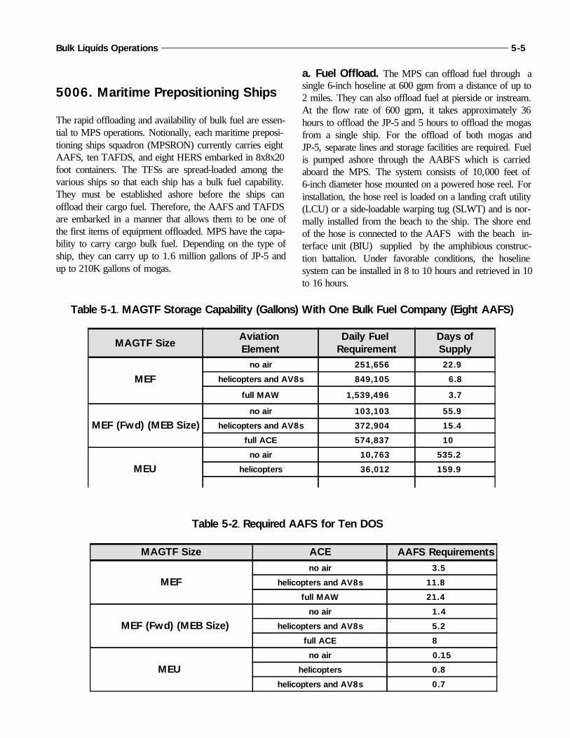
5006. Maritime Prepositioning Ships
The rapid offloading and availability of bulk fuel are essen-tial to MPS operations. Notionally, each maritime preposi-tioning ships squadron (MPSRON) currently carries eightAAFS, ten TAFDS, and eight HERS embarked in 8x8x20foot containers. The TFSs are spread-loaded among thevarious ships so that each ship has a bulk fuel capability.They must be established ashore before the ships canoffload their cargo fuel. Therefore, the AAFS and TAFDSare embarked in a manner that allows them to be one ofthe first items of equipment offloaded. MPS have the capa-bility to carry cargo bulk fuel. Depending on the type ofship, they can carry up to 1.6 million gallons of JP-5 andup to 210K gallons of mogas.
a. Fuel Offload. The MPS can offload fuel through asingle 6-inch hoseline at 600 gpm from a distance of up to2 miles. They can also offload fuel at pierside or instream.At the flow rate of 600 gpm, it takes approximately 36hours to offload the JP-5 and 5 hours to offload the mogasfrom a single ship. For the offload of both mogas andJP-5, separate lines and storage facilities are required. Fuelis pumped ashore through the AABFS which is carriedaboard the MPS. The system consists of 10,000 feet of6-inch diameter hose mounted on a powered hose reel. Forinstallation, the hose reel is loaded on a landing craft utility(LCU) or a side-loadable warping tug (SLWT) and is nor-mally installed from the beach to the ship. The shore endof the hose is connected to the AAFS with the beach in-terface unit (BIU) supplied by the amphibious construc-tion battalion. Under favorable conditions, the hoselinesystem can be installed in 8 to 10 hours and retrieved in 10to 16 hours.
Bulk Liquids Operations 5-5
MAGTF Size ACE AAFS Requirements
MEFno air 3.5
helicopters and AV8s 11.8
full MAW 21.4
MEF (Fwd) (MEB Size)no air 1.4
helicopters and AV8s 5.2
full ACE 8
MEU
no air 0.15
helicopters 0.8
helicopters and AV8s 0.7
MAGTF SizeAviation Element
Daily Fuel Requirement
Days ofSupply
MEFno air 251,656 22.9
helicopters and AV8s 849,105 6.8
full MAW 1,539,496 3.7
MEF (Fwd) (MEB Size)no air 103,103 55.9
helicopters and AV8s 372,904 15.4
full ACE 574,837 10
MEUno air 10,763 535.2
helicopters 36,012 159.9
Table 5-2. Required AAFS for Ten DOS
Table 5-1. MAGTF Storage Capability (Gallons) With One Bulk Fuel Company (Eight AAFS)
b. Unloading Fuel Systems. Early unloading of thefuel systems allows for installation to begin while the restof the equipment is being offloaded. All fuel-consumingequipment being offloaded should be filled on the ships be-fore offload. This will reduce the immediate need forshore-based fuel support. Mobile refuelers should also befilled before offloading so they can provide required fuelsupport ashore. Once the ship has offloaded its cargo, itcan then be positioned to deploy the hose reel and offloadits cargo fuel to the AAFS. In the time it takes to offloadthe equipment from the ship and deploy the hose reel,
the AAFS installation should be to the point that it canstart receiving fuel. During site selection for MPS, op-erations planners need to consider terrain requirements and
locations for the bulk fuel systems and the ship-to-shorefuel transfer.
5007. Bulk Fuel Reports
Bulk fuel reporting requirements and procedures will varydepending on the exercise and/or operation. Appendixes Bthrough D are examples of bulk fuel reports that may berequired of the MAGTF in a joint environment. These ex-amples are from the United States Message Text Format(USMTF) Handbook.
5-6 MCWP 4-25.5
6001. References
The requirements and procedures for the accountability ofpetroleum products are in DOD 4140.25-M and MaineCorps Order 4400.17O, Control and Accounta- bility ofPetroleum and Related Products and Coal. These refer-ences provide policy and guidance for the accountability ofpetroleum products by Marine Corps activities.
Regardless of the type of fuel equipment being used, unitsmust maintain accounting procedures and records as accu-rately as possible. This applies to fixed facilities, mobilerefueling equipment, and TFSs. Accounting for fuel infixed facilities and mobile equipment is fairly accurate.However, when bulk fuel units perform a physical inven-tory for TFSs, the physical inventory becomes more diffi-cult and less accurate due to the use of collapsible tanksand miles of tactical hose that may be employed. The keyto more accurate accounting for TFSs is for commanders
and their staff is to ensure that local bulk fuel SOPsaddress unit procedures and requirements for fuel account-ability when using TFSs.
6002. Inventory ManagementProcedures
Inventory management procedures depend on whether thefuel is owned by DOD (wholesale) or by the Service (re-tail). DOD fuel is purchased at the wholesale level byDFSC for direct delivery to the customer. When the Serv-ice orders and receives fuel from a defense fuel supplypoint (DFSP) or a DFSC contract, a “sale” takes place,and the fuel becomes Service-owned retail stock.
Whether a Service is holding wholesale or retail bulk fuelstocks, certain rules of accounting apply to all Services.All bulk fuel holding activities should maintain a propertybook or logbook inventory record and a physical inventoryrecord. Property book records are an administrative (check
Chapter 6
Bulk Fuel Inventory Management
The management of fuel inventories involves a full range of actions associated withorders/requisitions, receipt, transfer, issue, and storage of fuel. Bulk fuel supportmust be planned so product quantities are maintained to support planned opera-tions. The major objectives of an inventory management program are to—
Ensure that all orders, receipts, transfers, issues, losses, gains, and adjustmentsare properly documented.
Maintain accountable records on all products.
Ensure that an audit trail of fuel transactions is performed.
Maintain control over the physical environment to ensure that proper productstorage can take place with minimal losses.
Ensure that fuel losses are held to a minimum.
book) record that provides an audit of all receipts, trans-fers, and issues and provide an estimate of the fuel inven-tory on hand. They are kept on a daily basis. Physicalinventory is a physical measurement of the actual fuel onhand at 60 degrees Fahrenheit. A physical inventory is conducted periodically (daily, weekly, monthly) depend-ing on the situation. When a physical inventory is con-ducted, the responsible bulk fuel unit adjusts the on-handfuel quantity recorded in the property book records to theactual quantity of the physical inventory. If the differencebetween the property book records and the physical inven-tory exceed the allowable loss/gain, it must be reportedthrough the chain of command.
6003. Fuel Accountability
As with all supplies, the commander considers the ac-countability of bulk fuel essential. Commanders are alsoaware that procedures and requirements for bulk fuel ac-countability will vary depending on the operation, the typeof fuel equipment being used, and the situation (i.e., com-bat, training exercise, joint operations, etc.). To ensureproper and sound accounting procedures are being fol-lowed, the commander and staff need to ensure that ac-counting procedures are contained in operation plans andexercise letters of instruction.
However, due to the nature of fuel, certain losses will oc-cur as a result of evaporation, transportation, storage, andhandling. Allowable tolerances have been established forthese losses and gains by the American Petroleum Institute(API) and adopted by the DOD. There are many variablesinvolved in accounting procedures to be followed. How-ever, the following procedures are common and apply toall bulk fuel operations.
Access to fuel tanks must be controlled. Quality andquantity inspections must be made on all receipts priorto accepting fuel into a storage system. At a minimum,samples should be checked for water and sediment andto ensure that the fuel is “clear and bright.” If the fueldoes not meet specifications, it should not be off-loadedand the senior fuel personnel should be contacted.
The quantity of a fuel delivery should be validated priorto off-loading. This is done by ensuring the vehicle isloaded to the proper fill mark and all seals (if applica-ble) are intact.
Truck meters are authorized for recording receipts if themeters are calibrated semi-annually. If necessary,
before and after gauging of the receiving tank will beconducted to verify quantity.
The unit of measurement for all fuel receipts is the U.S.gallon at 60 degrees F. Each receipt and issue greaterthan 3,500 gallons will be corrected for volume to 60degrees F. In accordance with MCO 4400.170, all re-ceipts from commercial tankers regardless of quantitywill be corrected for volume to 60 degrees F. All cor-rections will be done using Tables 5B and 6B, ASTMD1250-80.
Discrepancies must be documented and reported whichare in excess of allowable losses/gains per local direc-tives between the bill of lading and actual deliveryamounts.
Only authorized personnel will make fuel issues. Theattendant must be present for issues to record any re-quired information. Documentation must be completeand verification of random issues is recommended.Proper audit trails must be maintained. Special attentionis necessary with issues to other than end-use vehicles(i.e., portable containers or trucks used for multiple de-liveries) to ensure that proper authorization is obtained.
6004. Reports
Daily status reports, daily fuels issue reports, and monthlybulk fuel accounting summaries are used to maintain ac-countability of bulk fuel receipts, issues, and stocks onhand.
a. Daily Status Report. The daily status report is anadministrative report for the fiscal accounting of bulk fuelissued by Marine forces. The report is prepared at the bulkfuel supply point and submitted to higher headquarters. Higher headquarters then use this report to determine allo-cation adjustments and maintain continuous bulk fuel sup-port. This may be prepared an informal report format oraccording to one that the commander prescribes. Table 6-1is an example of a daily status report.
b. Daily Fuels Issue Report. Table 6-2 is an exam-ple of a daily fuels issue report. This can be maintained asan official logbook or produced as a single report.
c. Monthly Bulk Fuel Accounting Summary.Table 6-3 is an example of a monthly bulk fuel accountingsummary. It is used to report all gains or losses identified
6-2 MCWP 4-25.5

in the inventories. Inventory losses on this form must besupported by a report of survey if the losses exceed thoseallowed by MCO 4400.170 or are disapproved by the ap-proving authority. Gains in excess of the allowable limit-must be investigated to determine the cause. The reportshould be completed by the bulk fuel unit and submitted tohigher headquarters.
6005 Wartime Accounting
Peacetime procedures and responsibilities for the account-ability of bulk fuel will not be practical in wartime due tothe highly mobile combat environment. Summary fuel ac-counting is then enacted; it gives the Services discretionaryauthority to stop property book or stock record accounting.The unified CINC can determine when operations warranta transition from formal fuel accounting to summary fuelaccounting. Summary accounting applies only to fuel offi-cially received by the Service from DFSC.
Bulk Liquids Operations 6-3
Table 6-1. Sample Daily Status Report
ISSUES
Unit Name Product Qty this ReportTotal Qty to Date
HMM-164 JP5 25,000 80,000
MWSS-172 MoGas 500 2,000
Qty issued to ground equipment (green dollars)
5,000 20,000
Qty issued to aircraft (blue dollars) 20,000 60,000
RECEIPTS
Product Source Qty this Report Total Qty to Date JP5 MCAS CPNC 25,000 gal 100,000 gal
MoGas MCB CLNC 1,200 gal 2,500 gal
Unit Submitting Report: MWSS-174 Fuel Branch
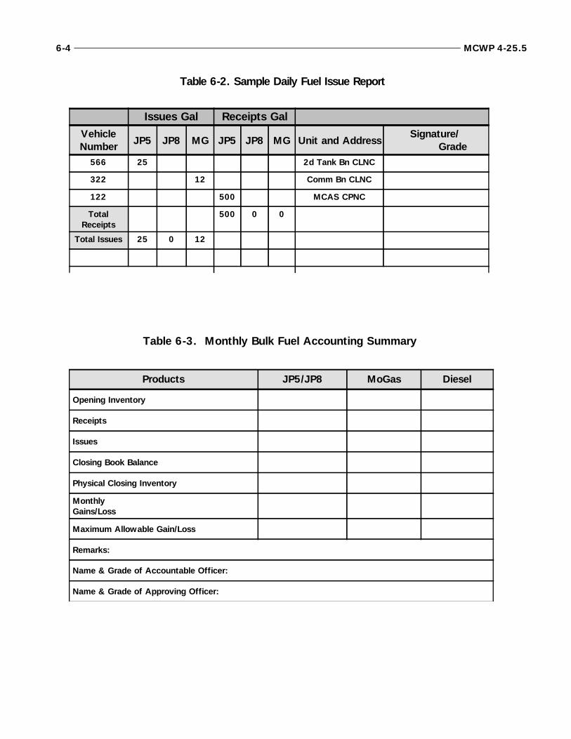
6-4 MCWP 4-25.5
Products JP5/JP8 MoGas Diesel
Opening Inventory
Receipts
Issues
Closing Book Balance
Physical Closing Inventory
Monthly Gains/Loss
Maximum Allowable Gain/Loss
Remarks:
Name & Grade of Accountable Officer:
Name & Grade of Approving Officer:
Issues Gal Receipts GalVehicleNumber JP5 JP8 MG JP5 JP8 MG Unit and Address
Signature/ Grade
566 25 2d Tank Bn CLNC
322 12 Comm Bn CLNC
122 500 MCAS CPNC
TotalReceipts
500 0 0
Total Issues 25 0 12
Table 6-3. Monthly Bulk Fuel Accounting Summary
Table 6-2. Sample Daily Fuel Issue Report

7001. Quality Assurance Program
To meet specifications set by DOD, petroleum productsundergo quality surveillance from time of purchase untilused. The JPO, responsible to the theater commander, en-sures there is a quality surveillance program within thecommand and monitors and assists Service components inthis program. The theater Army command is responsiblefor setting up and maintaining a quality surveillance pro-gram to support theater Army users. Each Service compo-nent is responsible for establishing and maintaining aquality surveillance program for Service petroleum stocks.
7002. Marine Corps Quality Assurance Program
A vigilant quality surveillance program implemented byproperly trained personnel is necessary to protect the origi-nal product quality. The fuel systems of modern aircraftand ground vehicles will not function properly if fuel iscontaminated with dirt, water, other fuel, or any foreignmatter. Actions will be taken to ensure that the productconforms to established technical requirements. These ac-tions include preventive maintenance (PM) of equipment,mandatory use of filter separators for aviation fuels (andhighly recommended for ground fuels), daily recirculationand visual examination of the product, proper storage,handling, and drainage of water bottoms, and proper con-centrations of additives such as fuel system icing inhibitor(FSII). The Military Handbook 200 (MIL-HDBK-200) is
the approved DOD reference for quality surveillance andshould be referred to in any cases of dispute.
a. Bulk Fuel Personnel. The bulk fuel officer (MOS1390) or the bulk fuel SNCOIC (MOS 1391) is responsi-ble for establishing procedures that will ensure the qualityof bulk fuel products that are stored and issued. All fuelhandling personnel are responsible for following estab-lished procedures and ensuring they take the required stepsto deliver clean fuel to vehicles and aircraft.
An effective quality surveillance program requires prop-erly trained personnel. Every Marine involved in handlingpetroleum should be suitably trained in quality control.The activity having physical possession of a product is re-sponsible for quality surveillance. Local SOPs must con-form to Table II, III, and IV of the MIL-HDBK-200 fortesting requirements.
b. Tactical Petroleum Laboratory, Medium(TPLM). Each FSSG rates two TPLMs (TAMNCB0695) and is responsible for correlation testing for allMEF units in accordance with MCO 11275. The TPLMis capable of full “B” level testing. The FSSG is also re-sponsible for fuel testing that exceeds other units’capabilities.
c. Detecting Contaminated Aviation Fuel. EachMWSS fuel branch rates the contaminated fuel detector(CFD) and the aviation fuel contamination test kit. TheMWSS is responsible for the quality surveillance programfor aviation fuels aboard airfields. NAVAIR 00-80T-109,
Chapter 7
Bulk Fuel Quality Surveillance
Quality surveillance is the process of determining and maintaining the quality ofgovernment-owned petroleum and related products so that these products are suit-able for their intended use. The quality of petroleum products is controlled at originby the DFSC. After receipt of the petroleum products, each Service is responsiblefor continued surveillance to maintain the quality of petroleum products.
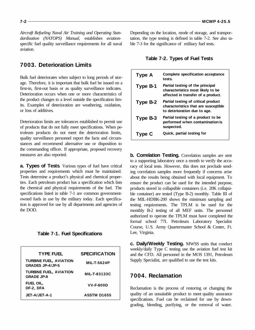
Aircraft Refueling Naval Air Training and Operating Stan-dardization (NATOPS) Manual, establishes aviation-specific fuel quality surveillance requirements for all navalaviation.
7003. Deterioration Limits
Bulk fuel deteriorates when subject to long periods of stor-age. Therefore, it is important that bulk fuel be issued on afirst-in, first-out basis or as quality surveillance indicates.Deterioration occurs when one or more characteristics ofthe product changes to a level outside the specification lim-its. Examples of deterioration are weathering, oxidation,or loss of additives.
Deterioration limits are tolerances established to permit useof products that do not fully meet specifications. When pe-troleum products do not meet the deterioration limits,quality surveillance personnel report the facts and circum-stances and recommend alternative use or disposition tothe commanding officer. If appropriate, proposed recoverymeasures are also reported.
a. Types of Tests. Various types of fuel have criticalproperties and requirements which must be maintained.Tests determine a product’s physical and chemical proper-ties. Each petroleum product has a specification which liststhe chemical and physical requirements of the fuel. Thespecifications listed in table 7-1 are common government-owned fuels in use by the military today. Each specifica-tion is approved for use by all departments and agencies ofthe DOD.
Depending on the location, mode of storage, and transpor-tation, the type testing is defined in table 7-2. See also ta-ble 7-3 for the significance of military fuel tests.
b. Correlation Testing. Correlation samples are sentto a supporting laboratory once a month to verify the accu-racy of local tests. However, this does not preclude send-ing correlation samples more frequently if concerns ariseabout the results being obtained with local equipment. Toensure the product can be used for the intended purpose,products stored in collapsible containers (i.e. 20K collapsi-ble container) are tested (Type B-2) monthly. Table III ofthe MIL-HDBK-200 shows the minimum sampling andtesting requirements. The TPLM is be used for themonthly B-2 testing of all MEF units. The personnelauthorized to operate the TPLM must have completed theformal school 77L Petroleum Laboratory SpecialistCourse, U.S. Army Quartermaster School & Center, Ft.Lee, Virginia.
c. Daily/Weekly Testing. MWSS units that conductweekly/daily Type C testing use the aviation fuel test kitand the CFD. All personnel in the MOS 1391, PetroleumSupply Specialist, are qualified to use the test kits.
7004. Reclamation
Reclamation is the process of restoring or changing thequality of an unsuitable product to meet quality assurancespecifications. Fuel can be reclaimed for use by down-grading, blending, purifying, or the removal of water.
7-2 MCWP 4-25.5
TYPE FUEL SPECIFICATIONTURBINE FUEL, AVIATIONGRADES JP-4/JP-5
MIL-T-5624P
TURBINE FUEL, AVIATIONGRADE JP-8
MIL-T-83133C
FUEL OIL,DF-2, DFA
VV-F-800D
JET-A/JET-A-1 ASSTM D1655
Table 7-1. Fuel Specifications
Type A Complete specification acceptancetests.
Type B-1 Partial testing of the principalcharacteristics most likely to beaffected in transfer of a product.
Type B-2 Partial testing of critical productcharacteristics that are susceptibleto deterioration due to age.
Type B-3 Partial testing of a product to beperformed when contamination issuspected.
Type C Quick, partial testing for
Table 7-2. Types of Fuel Tests

Fuel that cannot be used for its intended purpose may beused as a lower grade of the same or similar product if itmeets that product’s specifications.
The most common causes of off-specification fuel are con-tamination and deterioration. Contamination occurs whenone or more grades or types of products are inadvertentlymixed, or a product contains foreign matter such as dirt,dust, rust, water, or emulsions. Once a product has beenidentified as being off-specification, the following reclama-tion procedures can be taken:
Downgrading. Approval for an off-specification orcontaminated product for other than its intended use.
Blending. Predetermined quantities of two or moresimilar products are mixed to produce a petroleumproduct or intermediate grade or quality.
Purification. The removal of contaminating agents byfiltration or dehydration.
Dehydration. The removal of water by a filtering orsettling process. Water in most light products will set-tle out if allowed to stand undisturbed for 12 - 24 hours.
Inhibiting. Adding or restoring additives.
Disposal. Defense Reutilization Marketing Office(DRMO) should be a last resort as to the disposition ofthe product.
7005. Captured Fuel
Any captured fuel should be tested prior to use. The timeand mission will dictate the extent of testing.
Bulk Liquids Operations 7-3
Knock Values
Knock values indicate whether a fuel will burn uniformly andevenly in a cylinder without pre-ignition or detonation. Theknock values are expressed as octane numbers forautomotive-type engine gasoline and as a combination ofoctane and performance numbers for aviation gasoline.These values are determined by comparing the knockingtendency of fuel samples to those of standard test fuels ofknown knock values in a standard test engine. Fuel of inade-quate knock value will reduce the power output of all typesof engines. If used for more than brief periods, it couldcause overheating of the engine, burned or melted pistonsand cylinders, and lubrication failure.
Cetane Number
The ignition quality of a diesel fuel, which is based on a scaleresembling that of an octane number, is expressed as acetane number. This number indicates the length of time (ig-nition lag) between injection of the fuel and combustion. Thecetane number requirement varies with the type of diesel en-gine. Large and slow-speed units in stationary installa- tionsdo not require diesel fuel with cetane ratings above 40.Smaller, high-speed engines (1000 rpm or more) require fuelof a higher cetane number. In the absence of test engines,cetane numbers are approximated from the calculated cetaneindex.
Table 7-3. Significance of Military Fuel Tests
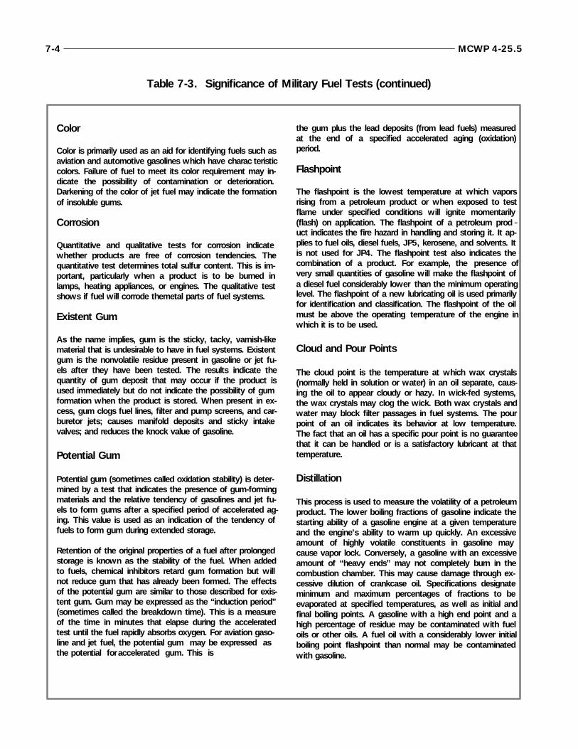
7-4 MCWP 4-25.5
Color
Color is primarily used as an aid for identifying fuels such asaviation and automotive gasolines which have charac teristiccolors. Failure of fuel to meet its color requirement may in-dicate the possibility of contamination or deterioration.Darkening of the color of jet fuel may indicate the formationof insoluble gums.
Corrosion
Quantitative and qualitative tests for corrosion indicatewhether products are free of corrosion tendencies. Thequantitative test determines total sulfur content. This is im-portant, particularly when a product is to be burned inlamps, heating appliances, or engines. The qualitative testshows if fuel will corrode the metal parts of fuel systems.
Existent Gum
As the name implies, gum is the sticky, tacky, varnish-likematerial that is undesirable to have in fuel systems. Existentgum is the nonvolatile residue present in gasoline or jet fu-els after they have been tested. The results indicate thequantity of gum deposit that may occur if the product isused immediately but do not indicate the possibility of gumformation when the product is stored. When present in ex-cess, gum clogs fuel lines, filter and pump screens, and car-buretor jets; causes manifold deposits and sticky intakevalves; and reduces the knock value of gasoline.
Potential Gum
Potential gum (sometimes called oxidation stability) is deter-mined by a test that indicates the presence of gum-formingmaterials and the relative tendency of gasolines and jet fu-els to form gums after a specified period of accelerated ag-ing. This value is used as an indication of the tendency offuels to form gum during extended storage.
Retention of the original properties of a fuel after prolongedstorage is known as the stability of the fuel. When addedto fuels, chemical inhibitors retard gum formation but willnot reduce gum that has already been formed. The effectsof the potential gum are similar to those described for exis-tent gum. Gum may be expressed as the “induction period”(sometimes called the breakdown time). This is a measureof the time in minutes that elapse during the acceleratedtest until the fuel rapidly absorbs oxygen. For aviation gaso-line and jet fuel, the potential gum may be expressed as the potential for accelerated gum. This is
the gum plus the lead deposits (from lead fuels) measuredat the end of a specified accelerated aging (oxidation)period.
Flashpoint
The flashpoint is the lowest temperature at which vaporsrising from a petroleum product or when exposed to testflame under specified conditions will ignite momentarily(flash) on application. The flashpoint of a petroleum prod -uct indicates the fire hazard in handling and storing it. It ap-plies to fuel oils, diesel fuels, JP5, kerosene, and solvents. Itis not used for JP4. The flashpoint test also indicates thecombination of a product. For example, the presence ofvery small quantities of gasoline will make the flashpoint ofa diesel fuel considerably lower than the minimum operatinglevel. The flashpoint of a new lubricating oil is used primarilyfor identification and classification. The flashpoint of the oilmust be above the operating temperature of the engine inwhich it is to be used.
Cloud and Pour Points
The cloud point is the temperature at which wax crystals(normally held in solution or water) in an oil separate, caus-ing the oil to appear cloudy or hazy. In wick-fed systems,the wax crystals may clog the wick. Both wax crystals andwater may block filter passages in fuel systems. The pourpoint of an oil indicates its behavior at low temperature.The fact that an oil has a specific pour point is no guaranteethat it can be handled or is a satisfactory lubricant at thattemperature.
Distillation
This process is used to measure the volatility of a petroleumproduct. The lower boiling fractions of gasoline indicate thestarting ability of a gasoline engine at a given temperatureand the engine’s ability to warm up quickly. An excessiveamount of highly volatile constituents in gasoline maycause vapor lock. Conversely, a gasoline with an excessiveamount of “heavy ends” may not completely burn in thecombustion chamber. This may cause damage through ex-cessive dilution of crankcase oil. Specifications designateminimum and maximum percentages of fractions to beevaporated at specified temperatures, as well as initial andfinal boiling points. A gasoline with a high end point and ahigh percentage of residue may be contaminated with fueloils or other oils. A fuel oil with a considerably lower initialboiling point flashpoint than normal may be contaminatedwith gasoline.
Table 7-3. Significance of Military Fuel Tests (continued)
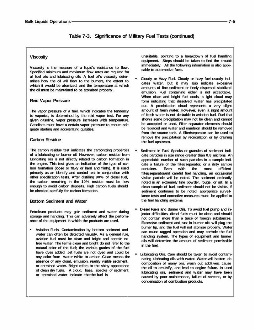
Bulk Liquids Operations 7-5
Viscosity
Viscosity is the measure of a liquid’s resistance to flow.Specified minimum and maximum flow rates are required forall fuel oils and lubricating oils. A fuel oil’s viscosity deter-mines how the oil will flow to the burners, the extent towhich it would be atomized, and the temperature at whichthe oil must be maintained to be atomized properly .
Reid Vapor Pressure
The vapor pressure of a fuel, which indicates the tendencyto vaporize, is determined by the reid vapor test. For anygiven gasoline, vapor pressure increases with temperature.Gasolines must have a certain vapor pressure to ensure ade-quate starting and accelerating qualities.
Carbon Residue
The carbon residue test indicates the carbonizing propertiesof a lubricating or burner oil. However, carbon residue fromlubricating oils is not directly related to carbon formation inthe engine. This test gives an indication of the type of car-bon formation (loose or flaky or hard and flinty). It is usedprimarily as an identify and control test in conjunction withother specification tests. After distilling 90% of diesel fuel,the carbon remaining in the 10% residue must be l owenough to avoid carbon deposits. High carbon fuels shouldbe checked carefully for carbon formation.
Bottom Sediment and Water
Petroleum products may gain sediment and water duringstorage and handling. This can adversely affect the perform-ance of the equipment in which the products are used.
Aviation Fuels. Contamination by bottom sediment andwater can often be detected visually. As a general rule,aviation fuel must be clean and bright and contain nofree water. The terms clean and bright do not refer to thenatural color of the fuel; the various grades of the fuelhave dyes added. Jet fuels are not dyed and could beany color from water white to amber. Clean means theabsence of any cloud, emulsion, readily visible sediment,or entrained water. Bright refers to the shiny appearanceof clean dry fuels. A cloud, haze, specks of sediment,or entrained water indicate that the fuel is
unsuitable, pointing to a breakdown of fuel handlingequipment. Steps should be taken to find the troubleimmediately. All the following information is also appli-cable to automotive fuels.
Cloudy or Hazy Fuel. Cloudy or hazy fuel usually indi-cates water, but it may also indicate excessiveamounts of fine sediment or finely dispersed stabilizedemulsion. Fuel containing either is not acceptable.When clean and bright fuel cools, a light cloud mayform indicating that dissolved water has precipitatedout. A precipitation cloud represents a very slightamount of fresh water. However, even a slight amountof fresh water is not desirable in aviation fuel. Fuel thatshows some precipitation may not be clean and cannotbe accepted or used. Filter separator elements shouldbe replaced and water and emulsion should be removedfrom the source tank. A filter/separator can be used toremove the precipitation by recirculation or by drainingthe fuel upstream.
Sediment in Fuel. Specks or granules of sediment indi-cate particles in size range greater than 0.8 microns. Anappreciable number of such particles in a sample indi-cate a failure of the filter/separator, or a dirty samplecontainer. Even with the most efficientfilter/separatorand careful fuel handling, an occasionalvisible particle will be noted. The sediment ordinarilynoted is an extremely fine powder, rouge, or silt. In aclean sample of fuel, sediment should not be visible. Ifsediment continues to be noted, appropriate surveil-lance tests and corrective measures must be applied tothe fuel handling systems.
Diesel Fuels and Burner Oils. To avoid fuel pump and in-jector difficulties, diesel fuels must be clean and shouldnot contain more than a trace of foreign substances.Excessive sediment and rust in burner oils will plug theburner tip, and the fuel will not atomize properly. Watercan cause ragged operation and may corrode the fuelhandling system. The types of equipment and burneroils will determine the amount of sediment permissiblein the fuel.
Lubricating Oils. Care should be taken to avoid contami-nating lubricating oils with water. Water will hasten de-composition of many oils, wash out additives, causethe oil to emulsify, and lead to engine failure. In usedlubricating oils, sediment and water may have beencaused by poor maintenance, failure of screens, or bycondensation of combustion products.
Table 7-3. Significance of Military Fuel Tests (continued)
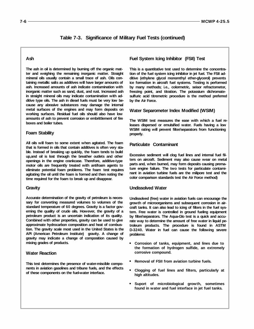
7-6 MCWP 4-25.5
Ash
The ash in oil is determined by burning off the organic mat-ter and weighing the remaining inorganic matter. Straightmineral oils usually contain a small trace of ash. Oils con-taining metallic salts as additives will have larger amounts ofash. Increased amounts of ash indicate contamination withinorganic matter such as sand, dust, and rust. Increased ashin straight mineral oils may indicate contamination with ad-ditive type oils. The ash in diesel fuels must be very low be-cause any abrasive substances may damage the internalmetal surfaces of the engines and may form deposits onworking surfaces. Residual fuel oils should also have lowamounts of ash to prevent corrosion or embrittlement of fireboxes and boiler tubes.
Foam Stability
All oils will foam to some extent when agitated. The foamthat is formed in oils that contain additives is often very sta-ble. Instead of breaking up quickly, the foam tends to buildup,and oil is lost through the breather outlets and otheropenings in the engine crankcase. Therefore, additive-typemotor oils are frequently treated with antifoam agents toeliminate potential foam problems. The foam test requiresagitating the oil until the foam is formed and then noting thetime required for the foam to break up and disappear.
Gravity
Accurate determination of the gravity of petroleum is neces-sary for converting measured volumes to volumes of thestandard temperature of 60 degrees. Gravity is a factor gov-erning the quality of crude oils. However, the gravity of apetroleum product is an uncertain indication of its quality.Combined with other properties, gravity can be used to giveapproximate hydrocarbon composition and heat of combus-tion. The gravity scale most used in the United States is theAPI (American Petroleum Institute) gravity. A change ofgravity may indicate a change of composition caused bymixing grades of products.
Water Reaction
This test determines the presence of water-miscible compo-nents in aviation gasolines and tribune fuels, and the effectsof these components on the fuel-water interface.
Fuel System Icing Inhibitor (FSII) Test
This is a quantitative test used to determine the concentra-tion of the fuel system icing inhibitor in jet fuel. The FSII ad-ditive (ethylene glycol monomthyl ether-glycerol) preventsice formation in aircraft fuel systems. Testing is performedby many methods; i.e., colormetric, seisor refractometor,freezing point, and titration. The potassium dichromate-sulfuric acid titremetric procedure is the method preferredby the Air Force.
Water Separometer Index Modified (WSIM)
The WSIM test measures the ease with which a fuel re-leases dispersed or emulsified water. Fuels having a lowWSIM rating will prevent filter/separators from functioningproperly.
Particulate Contaminant
Excessive sediment will clog fuel lines and internal fuel fil-ters on aircraft. Sediment may also cause wear on metalparts and, when burned, may form deposits causing prema-ture engine failure. The two tests for particulate contami-nant in aviation turbine fuels are the milipore test and thecolor comparison standards test the Air Force method).
Undissolved Water
Undissolved (free) water in aviation fuels can encourage thegrowth of microorganisms and subsequent corrosion in air-craft tanks. It can also lead to icing of filters in the fuel sys-tem. Free water is controlled in ground fueling equipmentby filter/separators. The Aqua-Glo test is a quick and accu-rate way to determine the amount of free water in liquid pe-troleum products. The procedure is found in ASTMD-3240. Water in fuel can cause the following severeproblems:
Corrosion of tanks, equipment, and lines due tothe formation of hydrogen sulfide, an extremelycorrosive compound.
Removal of FSII from aviation turbine fuels.
Clogging of fuel lines and filters, particularly athigh altitudes.
Suport of microbiological growth, sometimesfound in water and fuel interface in jet fuel tanks.
Table 7-3. Significance of Military Fuel Tests (continued)
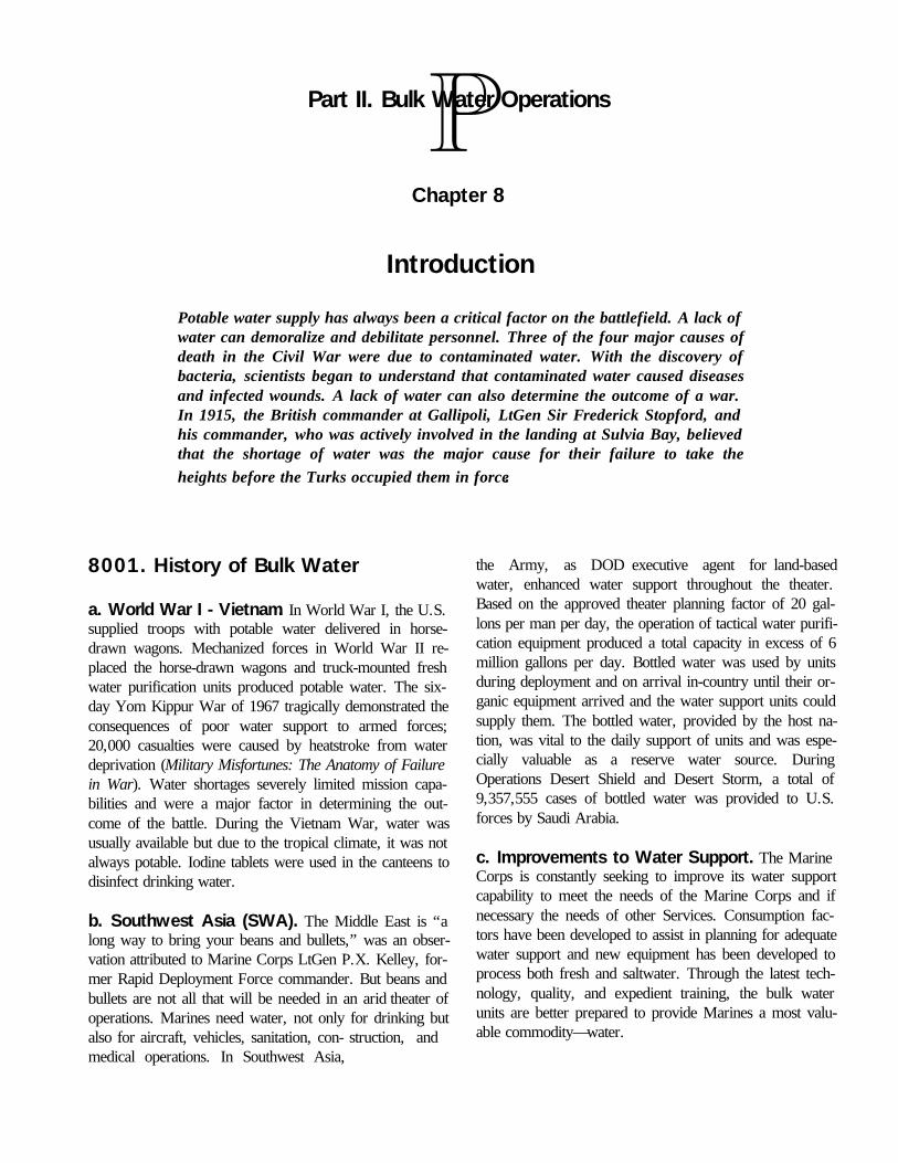
8001. History of Bulk Water
a. World War I - Vietnam. In World War I, the U.S.supplied troops with potable water delivered in horse-drawn wagons. Mechanized forces in World War II re-placed the horse-drawn wagons and truck-mounted freshwater purification units produced potable water. The six-day Yom Kippur War of 1967 tragically demonstrated theconsequences of poor water support to armed forces;20,000 casualties were caused by heatstroke from waterdeprivation (Military Misfortunes: The Anatomy of Failurein War). Water shortages severely limited mission capa-bilities and were a major factor in determining the out-come of the battle. During the Vietnam War, water wasusually available but due to the tropical climate, it was notalways potable. Iodine tablets were used in the canteens todisinfect drinking water.
b. Southwest Asia (SWA). The Middle East is “along way to bring your beans and bullets,” was an obser-vation attributed to Marine Corps LtGen P.X. Kelley, for-mer Rapid Deployment Force commander. But beans andbullets are not all that will be needed in an arid theater ofoperations. Marines need water, not only for drinking butalso for aircraft, vehicles, sanitation, con- struction, and medical operations. In Southwest Asia,
the Army, as DOD executive agent for land-basedwater, enhanced water support throughout the theater.Based on the approved theater planning factor of 20 gal-lons per man per day, the operation of tactical water purifi-cation equipment produced a total capacity in excess of 6million gallons per day. Bottled water was used by unitsduring deployment and on arrival in-country until their or-ganic equipment arrived and the water support units couldsupply them. The bottled water, provided by the host na-tion, was vital to the daily support of units and was espe-cially valuable as a reserve water source. DuringOperations Desert Shield and Desert Storm, a total of9,357,555 cases of bottled water was provided to U.S.forces by Saudi Arabia.
c. Improvements to Water Support. The MarineCorps is constantly seeking to improve its water supportcapability to meet the needs of the Marine Corps and ifnecessary the needs of other Services. Consumption fac-tors have been developed to assist in planning for adequatewater support and new equipment has been developed toprocess both fresh and saltwater. Through the latest tech-nology, quality, and expedient training, the bulk waterunits are better prepared to provide Marines a most valu-able commodity—water.
Potable water supply has always been a critical factor on the battlefield. A lack ofwater can demoralize and debilitate personnel. Three of the four major causes ofdeath in the Civil War were due to contaminated water. With the discovery ofbacteria, scientists began to understand that contaminated water caused diseasesand infected wounds. A lack of water can also determine the outcome of a war.In 1915, the British commander at Gallipoli, LtGen Sir Frederick Stopford, andhis commander, who was actively involved in the landing at Sulvia Bay, believedthat the shortage of water was the major cause for their failure to take theheights before the Turks occupied them in force.
Part II. Bulk Water Operations
Chapter 8
Introduction

8002. Concept of Bulk Water Operations
The basic concept of bulk water support is to source orproduce water as close to the user as possible. This re-quires proper planning of the water point selection for bulkwater, if required, and purification, storage, and distribu-tion of bulk water.
a. Bulk Water Support Responsibility. Bulk watersupport is normally a Service responsibility. However,during joint operations, the joint force commander may as-sign the Services areas of responsibility for water support.Areas of responsibility are usually assigned based on thepredominant user concept. This means that the greatest-volume user in an area would provide bulk water supportto all forces operating in the area. The actual proceduresused to provide bulk water support to the Services will de-pend on conditions in the area of operations.
b. Deployments. In most deployments, Marine Corpsforces will be capable of partial or complete water self-sufficiency using organic water equipment and host nationor commercial support. In geographic regions with ade-quate surface water resources, the commander is likely toestablish multiple water points in the vicinity of his forces.
c. Production and Storage. The production of wateris the purification of existing sources of water into potable
and non-potable water at a given water point. The extent towhich a water point is developed depends primarily on thetime, materials, and the Marines available to do the work.At forward sites, the water point will probably only be de-veloped to provide potable water to using units. In thelarger combat service support areas, the water point willprobably be developed to provide potable and non-potablewater support for the entire force.
Water storage at the production site should be sufficient tomeet the daily peak demands and allow water productionto continue. Having adequate water storage avoids frequenttime-consuming start-ups and shutdowns of the water pro-duction equipment.
d. Distribution. In most situations, water distribution isthe weak link of the water support system. Getting waterfrom the production and storage sites to the user can beequipment and manpower intensive. Marine forces mustmake efficient use of all available assets in conducting wa-ter distribution operations. Getting water from the storagesite to the using units can involve utilizing SIXCON watermodules, 500-gallon water drums, water cans, and bottledwater.
8-2 MCWP 4-25.5

9001. Water Equipment End Items
a. Shower Unit. The Shower Unit (TAMCN B0050)consists of six separate, identical, and interchangeableshower modules with interconnecting hoses, electric feedwater and drain pumps, and a drain hose. The unit has aself-contained, oil-fired boiler water heater capable of pro-viding 120 degree F water at a rate of 20 GPM. Thisshower unit will replace all trailer-mounted units.
b. Field Laundry Unit. The Laundry Unit (TAMCNB1226) is a pallet-mounted, self-contained unit. It consistsof a washer, dryer, extractor, and air compressor mountedon two pallets. The unit provides the capability to launder all washable fabrics worn by individual Marinesand bulky organizational items with a maximum output of120 pounds per hour.
c. 65 GPM Pump Set. The 65 GPM Pump Set(TAMCN B1620) is a compact, base-mounted, portablewater pump. It is comprised of a single stage centrifugalpump directly connected to an air-cooled gasoline engine.
d. 3,000 Gallon Collapsible Fabric Tank. The 3KTank (TAMCN B2130) is a collapsible tank designed foreasy application in the field. It has a 3,000 gallon capacityand may serve as a temporary or semi-permanent waterstorage facility.
e. Reverse Osmosis Water Purification Unit(ROWPU). The ROWPU (USMC TAMCN B2604) is aISO frame-mounted, portable water purification system. Itis powered by a 30KW generator set. The ROWPU canpurify almost any type of water, to include fresh, brackish,and salt water. It can also purify water that has been ex-posed to nuclear, biological, chemical (NBC) contami-nants. The ROWPU is capable of producing up to 600gallons per hour (gph) of potable water.
f. Medium Freshwater Purification Unit 3,000LMT. The medium freshwater purification unit is aframe-mounted, skid-based, diesel-operated, diatomite-type unit capable of purifying fresh water. It can purify upto 3,000 GPH from a freshwater source. This unit is thereplacement for the U22 Water Purification System.
g. Water Quality Analysis Kit - Purification. TheWater Quality Analysis Kit (WQAK) (TAMCN B2630)consists of the equipment necessary for testing water qual-ity. It is self-contained in a portable, waterproof suitcase.
h. Small Mobile Water Chiller. The Water Chiller(TAMCN B2641) is a skid-mounted, gasoline enginecooling unit. It can cool up to 40 GPM of potable waterfrom 120 degrees F to 60 degrees F. Although designedfor use with the M149 Water trailer, the water chiller iscompatible with other water storage assets.
Chapter 9
Water Equipment
Marine Corps water equipment has to meet a wide range of requirements, fromproviding support for near shore operations to supporting inland operations. Tomeet these requirements, the Marine Corps has developed various water equipmentend items and the family of water supply support system. USMC equipment has thecapability to purify both fresh water and salt water. However, the Marine Corpsdoes not have an organic well drilling capability. The MAGTF must be augmentedby elements from the naval construction force (NCF) in order to have thiscapability.

i. M149 Water Trailer. The M149 Water Trailer hasa 400-gallon stainless steel water tank. A manhole is lo-cated on the top of the water tank for filling and cleaning.There are four faucets and a drain faucet for dispensingwater. The trailer can be towed at a speed of 50 mph onthe highway and 30 mph cross country.
j. SIXCON. Specific SIXCON modules are designed forwater storage. Its main function is to provide a source ofpotable water to remote locations. A SIXCON is trans-portable by air or ground. Water SIXCON modules aresimilar to fuel SIXCON modules. Components of the wa-ter SIXCON system are a pump module and five watertank modules. The modules form a water distributionsource that can be transported as a unit or individually. Ta-ble 9-1 shows MPS and MEF allowances for waterequipment.
9002. Family of Water SupplySupport Systems
To provide flexible and responsive water support, the Ma-rine Corps has developed a family of water supply supportsystems. Each system is designed and configured specifi-cally to support a unique mission using similar compo-nents. The ability to alter fundamental systemconfigurations and interchangeability of components allowsthe creation of limitless combinations of tailored systems tomeet mission requirements. The family of water supplysupport systems consists of 22 TAMCNs. See table 9-2for MPSRON and MEF allowances.
9-2 MCWP 4-25.5
Table 9-1. Water Equipment Allowances
TAMCN NOMENCLATURE MPSRON-1 MPSRON-2 MPSRON-2 I MEF II MEF III MEFB0055 bath, shower unit 19 19 19 61 54 32
B1226 laundry unit, field 14 14 14 40 32 29
B1581 water pump module 55 55 55 * * *
B1620 65-gpm pump set 35 35 35 60 54 32
B2086 water tank module 215 215 215 300 264 204
B2130 3k collapsible tank 104 104 104 695 582 386
B2604 ROWPU 41 41 41 121 101 56
B2628medium freshwaterpurification unit * * * 35 32 20
B2630 WQAK * * * 12 12 7
B2641 water chiller 83 83 83 67 56 45
D0880 M149 water trailer 110 110 110 298 285 183
* Allowances to be determined
Legend: ROWPU - reverse osmosis water purification unit
WQAK - water quality analysis kit
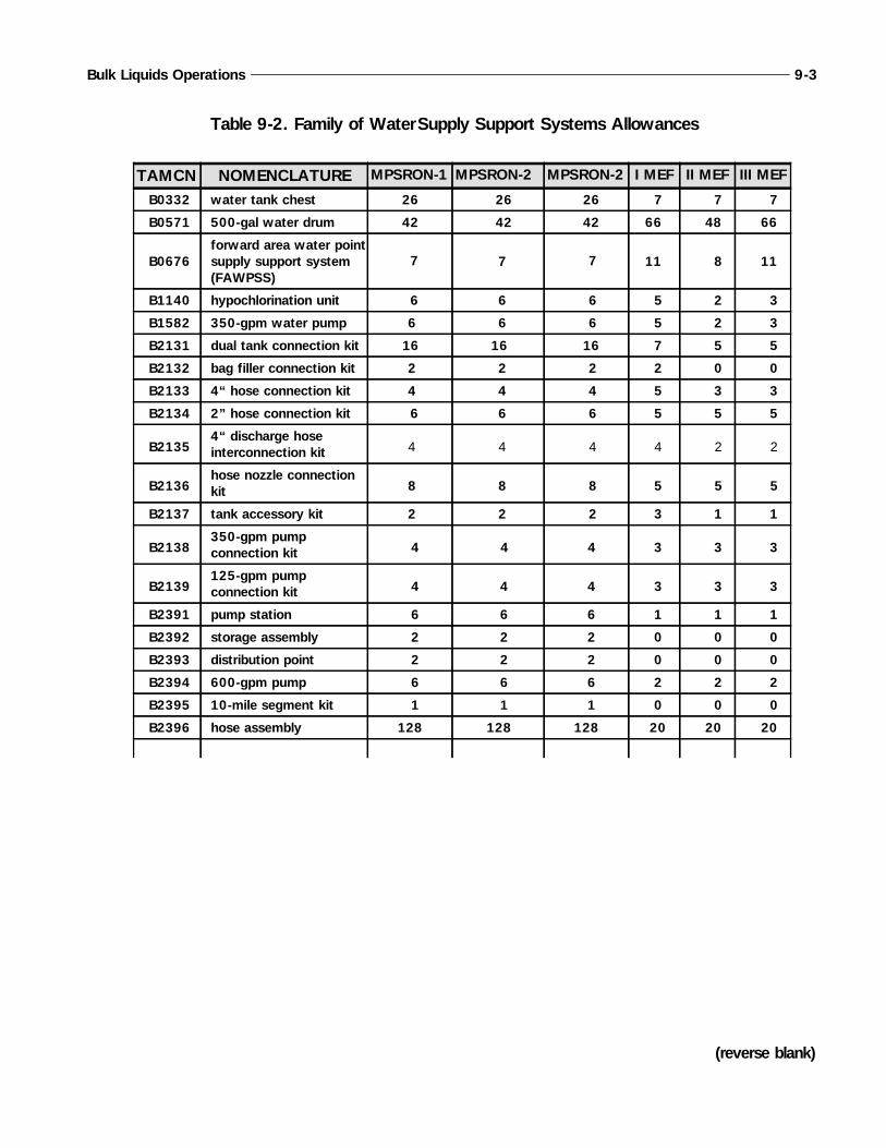
Bulk Liquids Operations 9-3
Table 9-2. Family of Water Supply Support Systems Allowances
TAMCN NOMENCLATURE MPSRON-1 MPSRON-2 MPSRON-2 I MEF II MEF III MEF
B0332 water tank chest 26 26 26 7 7 7
B0571 500-gal water drum 42 42 42 66 48 66
B0676forward area water pointsupply support system(FAWPSS)
7 7 7 11 8 11
B1140 hypochlorination unit 6 6 6 5 2 3
B1582 350-gpm water pump 6 6 6 5 2 3
B2131 dual tank connection kit 16 16 16 7 5 5
B2132 bag filler connection kit 2 2 2 2 0 0
B2133 4“ hose connection kit 4 4 4 5 3 3
B2134 2” hose connection kit 6 6 6 5 5 5
B21354“ discharge hoseinterconnection kit 4 4 4 4 2 2
B2136hose nozzle connectionkit 8 8 8 5 5 5
B2137 tank accessory kit 2 2 2 3 1 1
B2138350-gpm pumpconnection kit 4 4 4 3 3 3
B2139125-gpm pumpconnection kit 4 4 4 3 3 3
B2391 pump station 6 6 6 1 1 1
B2392 storage assembly 2 2 2 0 0 0
B2393 distribution point 2 2 2 0 0 0
B2394 600-gpm pump 6 6 6 2 2 2
B2395 10-mile segment kit 1 1 1 0 0 0
B2396 hose assembly 128 128 128 20 20 20
(reverse blank)
10001. Planning Guidance
Water planners at all levels must include water supply pro-cedures and guidance in exercise and operation plans. Thewater supply procedures are set forth in NAVMEDP-5010-5, Preventive Medicine Manual (Navy) or in TBMED 577, Occupational and Environmental Health Sani-tary Control and Surveillance of Field Water Supplies(Army). Planners also need to ensure that the force struc-ture has adequate resources for water production, storage,and distribution.
Water support planning is a continual process that beginswith the identification of the force size and planned deploy-ment rate. Time-phased water requirements are then deter-mined and units are selected and scheduled for deploymentbased on the requirements.
Some specific areas that are critical to effective water sup-port planning are as follows:
Development of detailed water distribution plans.
Identification of water support requirements for otherServices, allied forces, or host nation labor forces.
Water support structure (personnel and equipment) thatis capable of providing the required water purification,storage, and distribution.
Water quality procedures.
10002. Water Requirements
Planning for water support begins with determining waterrequirements. Water requirements will depend upon theenvironment, the tactical situation, and the size of theforce. Water requirements are flexible. They may not bethe same each day. Some requirements such as cookingmay be indefinite while others may only be for a specificperiod of time.
Chapter 10
Water Support Planning
The key to successful water support is innovative and flexible planning. Planning forwater support may range from a MAGTF contingency operation in areas without apre-established water support base to an operation involved in allied/host nation sup-port where water support is partially supplied. For contingency operations, water plan-ners must ensure that water units are structured to allow situation-dependent growthand maturity. This flexibility is a key to the MAGTF commander’s ability to supportthe operation.
Water support planning is a continual process that involves operational scenario, stra-tegic lift availability, and prepositioned supplies and equipment. Planning for watersupport must ensure that the MAGTF can perform its mission in the time required.Water support units and equipment need to be time phased in the area of operations(AO) so that water support and preventive medicine units arrive on time to provideadequate and continuous water support during an operation.
10003. Consumption Requirements
A number of water consumption requirements are basedon the size of the force. These are as follows:
Other water requirements are not directly related to thenumber of personnel. The combat environment, workload, and/or numbers of equipment determine theserequirements.
a. Region. Water consumption also depends on the re-gion. Water sources are normally abundant in temperate,arctic, and tropical regions. Since nonpotable water is eas-ily available in these areas, consumption estimates onlydeal with potable requirements. In arid regions, watersources are sparse and water must be transported forward.To prevent having two separate water systems in arid re-gions, requirements for both potable and nonpotable waterwill be met with potable water. As a result, total potablerequirements will increase in the arid regions. In all re-gions, plan for ten percent of the water to be lost throughevaporation or waste.
b. Requirements Determination. A number ofcomputations must be made to determine supply, purifica-tion, and storage requirements for water.
(1) Supply Requirement. To compute the totaldaily water requirement of the force, multiply theactual strength by the proper consumption factor.The total, expressed as gallons per day, includesten percent for evaporation and waste loss.
(2) Purification Requirement. The amount ofpurification equipment to support the daily re-quirement has to be determined. To do this, di-vide the total daily requirement by the dailyproduction capability of one purification unit. Un-der normal conditions, water purification equip-ment is operated twenty hours per day. However,many other factors affect the water production.Planners should coordinate with the equipmentoperators to get an accurate estimate of the waterproduction capability.
(3) Storage Requirement. Temperate, tropical,and arctic regions usually do not require largeamounts of water to be stored. Nonpotable re-quirements can be met by raw water sources, andthe potable requirements can be met by the waterpurification unit’s organic storage tanks. In aridregions, large quantities of potable water must bestored. The storage requirement is based on re-supply times, daily requirements, and the DOSrequirement established by the MAGTF com-mander.
c. Essential Consumption. When enough potablewater cannot be produced to meet all the requirements, allbut essential consumption must be reduced. Essential wa-ter requirements include drinking, personal hygiene, fieldfeeding, medical treatment, heat casualty treatment, and inarid regions, vehicle and aircraft maintenance. Consump-tion rates under these conditions are classified as “mini-mum”, enough for a force to survive up to one week.Requirements exceeding one week are classified as “sus-taining.” In this classification, nonessential consumptionincludes that for centralized hygiene, laundry, and con-struction. Tables 10-1 through 10-4 on the following pagesprovide water consumption data for each region—temper-ate, tropical, arctic, and arid.
10-2 MCWP 4-25.5
HospitalsNBC DecontaminationVehicle Maintenance
Drinking Heat Treatment Personal Hygiene
Food Preparation Laundering Centralized Hygiene
Graves Registration Engineer Construction Aircraft Washing
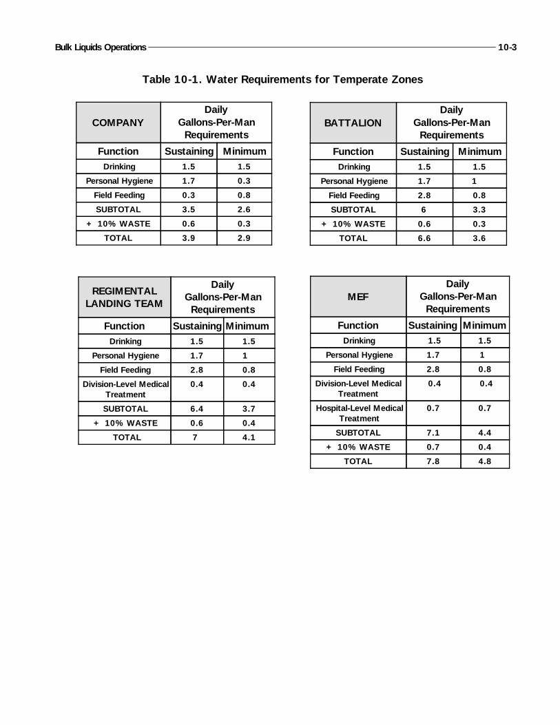
Bulk Liquids Operations 10-3
COMPANYDaily
Gallons-Per-ManRequirements
Function Sustaining MinimumDrinking 1.5 1.5
Personal Hygiene 1.7 0.3
Field Feeding 0.3 0.8
SUBTOTAL 3.5 2.6
+ 10% WASTE 0.6 0.3
TOTAL 3.9 2.9
BATTALIONDaily
Gallons-Per-ManRequirements
Function Sustaining MinimumDrinking 1.5 1.5
Personal Hygiene 1.7 1
Field Feeding 2.8 0.8
SUBTOTAL 6 3.3
+ 10% WASTE 0.6 0.3
TOTAL 6.6 3.6
REGIMENTALLANDING TEAM
DailyGallons-Per-ManRequirements
Function Sustaining MinimumDrinking 1.5 1.5
Personal Hygiene 1.7 1
Field Feeding 2.8 0.8
Division-Level MedicalTreatment
0.4 0.4
SUBTOTAL 6.4 3.7
+ 10% WASTE 0.6 0.4
TOTAL 7 4.1
MEFDaily
Gallons-Per-ManRequirements
Function Sustaining MinimumDrinking 1.5 1.5
Personal Hygiene 1.7 1
Field Feeding 2.8 0.8
Division-Level MedicalTreatment
0.4 0.4
Hospital-Level MedicalTreatment
0.7 0.7
SUBTOTAL 7.1 4.4
+ 10% WASTE 0.7 0.4
TOTAL 7.8 4.8
Table 10-1. Water Requirements for Temperate Zones
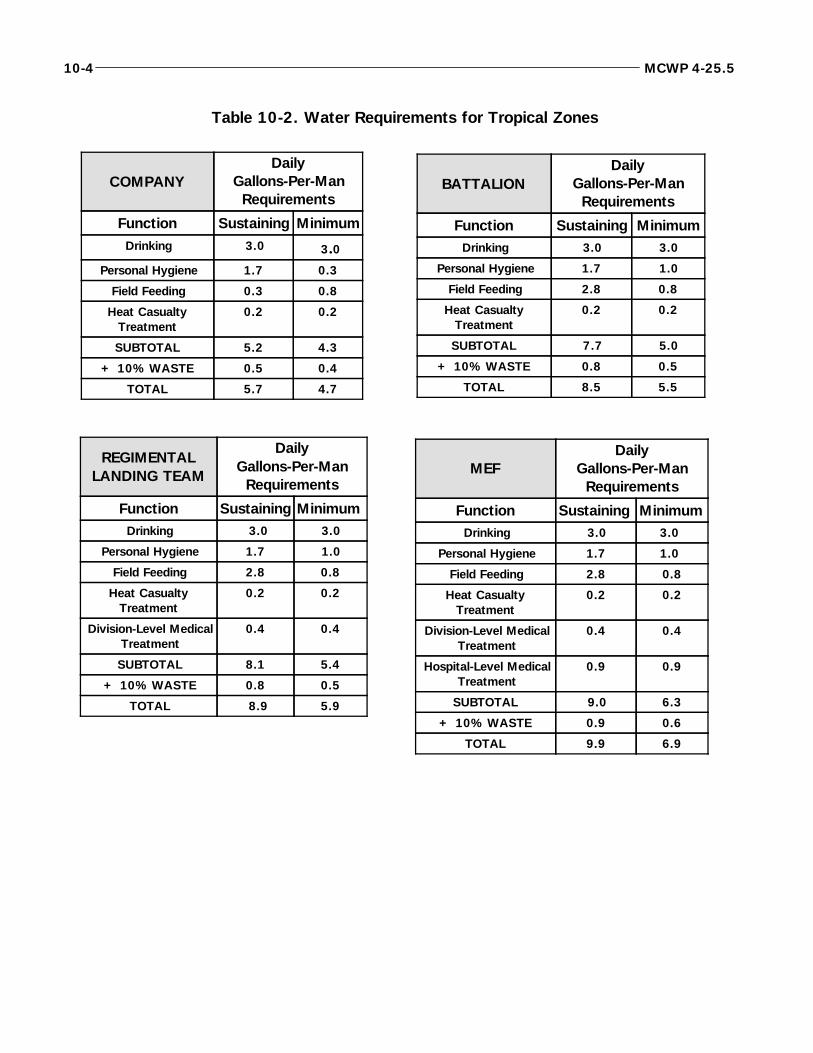
10-4 MCWP 4-25.5
COMPANYDaily
Gallons-Per-ManRequirements
Function Sustaining MinimumDrinking 3.0 3.0
Personal Hygiene 1.7 0.3
Field Feeding 0.3 0.8
Heat CasualtyTreatment
0.2 0.2
SUBTOTAL 5.2 4.3
+ 10% WASTE 0.5 0.4
TOTAL 5.7 4.7
BATTALIONDaily
Gallons-Per-ManRequirements
Function Sustaining MinimumDrinking 3.0 3.0
Personal Hygiene 1.7 1.0
Field Feeding 2.8 0.8
Heat CasualtyTreatment
0.2 0.2
SUBTOTAL 7.7 5.0
+ 10% WASTE 0.8 0.5
TOTAL 8.5 5.5
REGIMENTALLANDING TEAM
DailyGallons-Per-ManRequirements
Function Sustaining MinimumDrinking 3.0 3.0
Personal Hygiene 1.7 1.0
Field Feeding 2.8 0.8
Heat CasualtyTreatment
0.2 0.2
Division-Level MedicalTreatment
0.4 0.4
SUBTOTAL 8.1 5.4
+ 10% WASTE 0.8 0.5
TOTAL 8.9 5.9
MEFDaily
Gallons-Per-ManRequirements
Function Sustaining MinimumDrinking 3.0 3.0
Personal Hygiene 1.7 1.0
Field Feeding 2.8 0.8
Heat CasualtyTreatment
0.2 0.2
Division-Level MedicalTreatment
0.4 0.4
Hospital-Level MedicalTreatment
0.9 0.9
SUBTOTAL 9.0 6.3
+ 10% WASTE 0.9 0.6
TOTAL 9.9 6.9
Table 10-2. Water Requirements for Tropical Zones
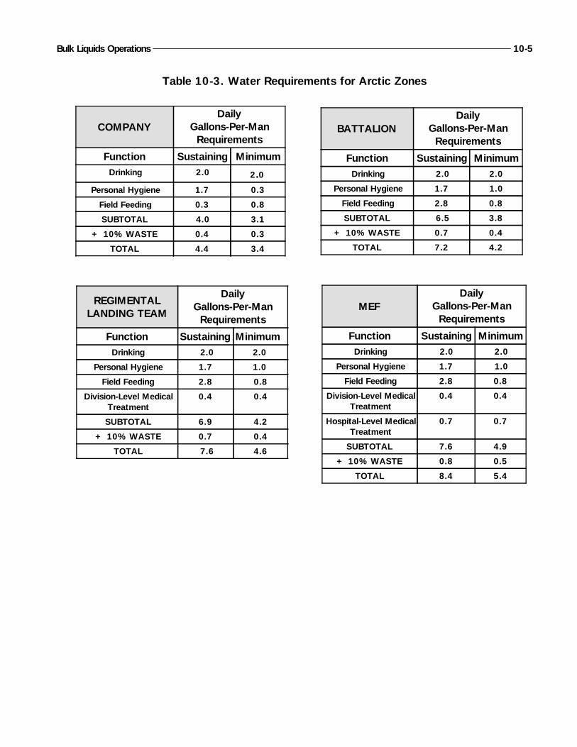
Bulk Liquids Operations 10-5
COMPANYDaily
Gallons-Per-ManRequirements
Function Sustaining MinimumDrinking 2.0 2.0
Personal Hygiene 1.7 0.3
Field Feeding 0.3 0.8
SUBTOTAL 4.0 3.1
+ 10% WASTE 0.4 0.3
TOTAL 4.4 3.4
REGIMENTALLANDING TEAM
DailyGallons-Per-ManRequirements
Function Sustaining MinimumDrinking 2.0 2.0
Personal Hygiene 1.7 1.0
Field Feeding 2.8 0.8
Division-Level MedicalTreatment
0.4 0.4
SUBTOTAL 6.9 4.2
+ 10% WASTE 0.7 0.4
TOTAL 7.6 4.6
BATTALIONDaily
Gallons-Per-ManRequirements
Function Sustaining MinimumDrinking 2.0 2.0
Personal Hygiene 1.7 1.0
Field Feeding 2.8 0.8
SUBTOTAL 6.5 3.8
+ 10% WASTE 0.7 0.4
TOTAL 7.2 4.2
MEFDaily
Gallons-Per-ManRequirements
Function Sustaining MinimumDrinking 2.0 2.0
Personal Hygiene 1.7 1.0
Field Feeding 2.8 0.8
Division-Level MedicalTreatment
0.4 0.4
Hospital-Level MedicalTreatment
0.7 0.7
SUBTOTAL 7.6 4.9
+ 10% WASTE 0.8 0.5
TOTAL 8.4 5.4
Table 10-3. Water Requirements for Arctic Zones
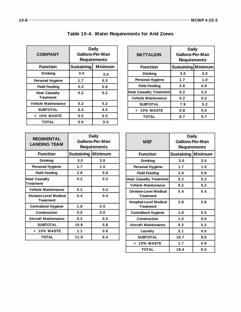
10-6 MCWP 4-25.5
COMPANYDaily
Gallons-Per-ManRequirements
Function Sustaining MinimumDrinking 3.0 3.0
Personal Hygiene 1.7 0.3
Field Feeding 0.3 0.8
Heat CasualtyTreatment
0.2 0.2
Vehicle Maintenance 0.2 0.2
SUBTOTAL 5.4 4.5
+ 10% WASTE 0.5 0.5
TOTAL 5.9 5.0
REGIMENTALLANDING TEAM
DailyGallons-Per-ManRequirements
Function Sustaining MinimumDrinking 3.0 3.0
Personal Hygiene 1.7 1.0
Field Feeding 2.8 0.8
Heat CasualtyTreatment
0.2 0.2
Vehicle Maintenance 0.2 0.2
Division-Level MedicalTreatment
0.4 0.4
Centralized Hygiene 1.8 0.0
Construction 0.5 0.0
Aircraft Maintenance 0.2 0.2
SUBTOTAL 10.8 5.8
+ 10% WASTE 1.1 0.6
TOTAL 11.9 6.4
BATTALIONDaily
Gallons-Per-ManRequirements
Function Sustaining MinimumDrinking 3.0 3.0
Personal Hygiene 1.7 1.0
Field Feeding 2.8 0.8
Heat Casualty Treatment 0.2 0.2
Vehicle Maintenance 0.2 0.2
SUBTOTAL 7.9 5.2
+ 10% WASTE 0.8 0.5
TOTAL 8.7 5.7
MEFDaily
Gallons-Per-ManRequirements
Function Sustaining MinimumDrinking 3.0 3.0
Personal Hygiene 1.7 1.0
Field Feeding 2.8 0.8
Heat Casualty Treatment 0.2 0.2
Vehicle Maintenance 0.2 0.2
Division-Level MedicalTreatment
0.4 0.4
Hospital-Level MedicalTreatment
2.8 2.8
Centralized Hygiene 1.8 0.0
Construction 1.5 0.0
Aircraft Maintenance 0.2 0.2
Laundry 2.1 0.0
SUBTOTAL 16.7 8.6
+ 10% WASTE 1.7 0.9
TOTAL 18.4 9.5
Table 10-4. Water Requirements for Arid Zones
11001. MAGTF Water Support
MAGTFs may require water support for contingency op-erations in areas without a pre-established water supportbase to an operation involving allied/host nation support.MAGTFs provide water support on an area basis usingsupply point distribution. Water support operations com-prises three areas—water purification, water storage, andwater distribution.
11002. MAGTF Water SupportResponsibilities
Normally the water supply system is an automatic resup-ply operation. Generally, its only limitations are wateravailability and the capability of receiving units. The for-ward movement of water is based on storage and distribu-tion assets available.
a. MAGTF Command Element. The commandelement is responsible for overall water support planningand operations for the MAGTF. When demand exceedssupply, the MAGTF commander establishes an allocationsystem and support procedures. The allocation system isbased on priorities to support the tactical plan.
To accomplish its mission, the CE performs the followingtasks:
Ensures water supply is sufficient to support theentire MAGTF and any other water missions as-signed by the JTF commander.
Submits required water data to the JTF or theaterArmy.
Directs Storage and distribution procedures andpriorities.
Chapter 11
Water Support Operations
Effective water support is essential to mission accomplishment. The water supportmission is to get potable water to each Marine. Each Service is responsible for itswater support. However, the Army is the theater manager for water support andmay provide backup water support when the Services’ requirements exceed their ca-pabilities. When a Service requires backup water support, the supported Servicemust provide detailed water requirements to the Army planners. The Army will pro-vide GS water support to other Services in the theater as required. FM 10-52, Wa-ter Supply in Theater of Operations, provides detailed information on Army rolesand responsibilities for water support in the theater. The Theater Army MaterialManagement Center monitors water priorities and allocation procedures and pro-vides the JTF commander with water supply data. During JTF operations, the JTFcommander may assign water support responsibilities on an area basis. Under this“predominant user concept”, the predominant Service in an area may be tasked toprovide water support to all Services operating in that area.

Provides inventory management of GS water sup-plies and sets allocations if required.
Ensures economy of management of all watersupport equipment within the MAGTF.
b. ACE, CSSE, and GCE. All other elements of theMAGTF are responsible for planning, directing, and su-pervising their organic water support assets. Each elementwill ensure it has the capabilities to perform any water sup-port tasking assigned by the MAGTF commander. Dailymanagement of the water points and water distribution isthe responsibility of the GCE, ACE, and CSSE. Watersupport requirements that are beyond the organic capabili-ties of an element will be passed to the MAGTF CE. EachMAGTF element has water purification, distribution, andstorage capability. However, the CSSE has the preponder-ance of water support equipment. As a result, the CSSEmust be prepared to provide GS to the other elements ofthe MAGTF as needed.
11003. Water Purification
Water purification is the first phase of water support opera-tions. During the purification phase, water is drawn fromthe source and purified to either potable or nonpotablestandards. Potable water is certified safe for human con-sumption. Nonpotable water is used for washing clothes,equipment, construction, and any other use that does notrequire human consumption. Water is purified with a Re-verse Osmosis Water Purification Unit (ROWPU) or aMedium Freshwater Purification Unit. Standards are veri-fied by a member of an Environmental Protection MedicalUnit or any Corpsman with a Water Quality Analysis Kitand the knowledge of how to use it.
11004. Water Storage
Water storage is the second phase of water support opera-tions. Storage is normally done at or very close to the puri-fication sites. The goal of water storage is to keep one dayof supply on hand. This will prevent a water shortage ifseveral purification units go down at one time. Storage canbe done with any water tight container on hand. Normally,it will be done using one or a combination of 3,000,20,000, and 50,000 gallon tanks. Water distribution beginsfrom the storage sight.
11005. Water Distribution
Water distribution is often the critical link in water supportoperations. If this link fails, the Marine goes thirsty. It isimportant that units organize so they will have sufficientorganic water distribution equipment to provide supplypoint distribution. Marine units must have enough waterdistribution capacity to supply minimum requirements forwater while making only one trip to the water point perday. During the early phases of deployments and in emer-gency situations, airlift of packaged water will be the pri-mary means of resupply in forward areas. As the CSSEsare established and LOCs are developed, units will beginpulling water from water points using organic 400-gallonwater trailers and SIXCON water modules.
a. Water Supply Operations in Arid Regions.Water sources are either nonexistent or extremely limitedin arid regions. The options available to the MAGTF willbe limited to importing water, desalination of seawater, ordevelopment of new water supply sources. Units will needto make maximum use of organic water equipment forstorage and distribution. Water purification teams and de-tachments will often be required to operate from the shorepurifying seawater with reverse osmosis water purificationunits (ROWPUs). The family of water supply supportequipment is used to store and distribute potable water tooperating forces. Water moved forward is either stored inforward water supply points or issued to the using units.Water supply points are established as far forward as pos-sible, considering the location of water sources, the loca-tion of using units, and the tactical plans. Based onresupply times and water availability, MAGTF command-ers will have to establish the required DOS for water to beheld at each echelon. Operational and direct support (DS)units will normally maintain a minimum of one DOS.
Water supply operations are conducted in three phases toensure effective and continual water support.
(1) Development Phase. This phase may begin as anair or amphibious assault or as an uncontested entry at afriendly port. The first MAGTF elements will probablybe combat forces with little CSS. Using canteens,5-gallon cans, and other organic equipment, theseforces carry only enough water for immediate survivalpurposes. Resupply must begin quickly by either air orfrom the sea. During this phase, packaged water will beprimarily provided from offshore or from the air fromnon-theater support bases. Nonexpendable equipmentused during this phase, such as 500-gallon drums and5-gallon cans, must be recovered and reused. MAGTF
11-2 MCWP 4-25.5
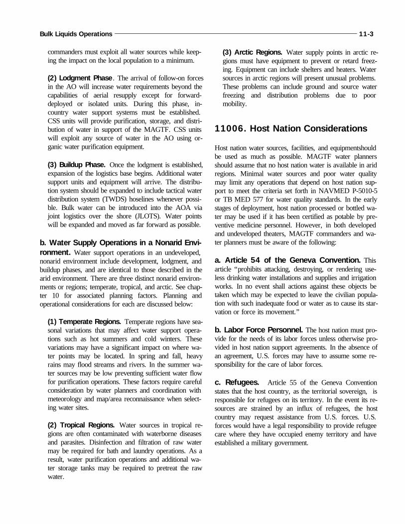
commanders must exploit all water sources while keep-ing the impact on the local population to a minimum.
(2) Lodgment Phase. The arrival of follow-on forcesin the AO will increase water requirements beyond thecapabilities of aerial resupply except for forward-deployed or isolated units. During this phase, in-country water support systems must be established.CSS units will provide purification, storage, and distri-bution of water in support of the MAGTF. CSS unitswill exploit any source of water in the AO using or-ganic water purification equipment.
(3) Buildup Phase. Once the lodgment is established,expansion of the logistics base begins. Additional watersupport units and equipment will arrive. The distribu-tion system should be expanded to include tactical waterdistribution system (TWDS) hoselines whenever possi-ble. Bulk water can be introduced into the AOA viajoint logistics over the shore (JLOTS). Water pointswill be expanded and moved as far forward as possible.
b. Water Supply Operations in a Nonarid Envi-ronment. Water support operations in an undeveloped,nonarid environment include development, lodgment, andbuildup phases, and are identical to those described in thearid environment. There are three distinct nonarid environ-ments or regions; temperate, tropical, and arctic. See chap-ter 10 for associated planning factors. Planning andoperational considerations for each are discussed below:
(1) Temperate Regions. Temperate regions have sea-sonal variations that may affect water support opera-tions such as hot summers and cold winters. Thesevariations may have a significant impact on where wa-ter points may be located. In spring and fall, heavyrains may flood streams and rivers. In the summer wa-ter sources may be low preventing sufficient water flowfor purification operations. These factors require carefulconsideration by water planners and coordination withmeteorology and map/area reconnaissance when select-ing water sites.
(2) Tropical Regions. Water sources in tropical re-gions are often contaminated with waterborne diseasesand parasites. Disinfection and filtration of raw watermay be required for bath and laundry operations. As aresult, water purification operations and additional wa-ter storage tanks may be required to pretreat the rawwater.
(3) Arctic Regions. Water supply points in arctic re-gions must have equipment to prevent or retard freez-ing. Equipment can include shelters and heaters. Watersources in arctic regions will present unusual problems.These problems can include ground and source waterfreezing and distribution problems due to poormobility.
11006. Host Nation Considerations
Host nation water sources, facilities, and equipmentshouldbe used as much as possible. MAGTF water plannersshould assume that no host nation water is available in aridregions. Minimal water sources and poor water qualitymay limit any operations that depend on host nation sup-port to meet the criteria set forth in NAVMED P-5010-5or TB MED 577 for water quality standards. In the earlystages of deployment, host nation processed or bottled wa-ter may be used if it has been certified as potable by pre-ventive medicine personnel. However, in both developedand undeveloped theaters, MAGTF commanders and wa-ter planners must be aware of the following:
a. Article 54 of the Geneva Convention. Thisarticle “prohibits attacking, destroying, or rendering use-less drinking water installations and supplies and irrigationworks. In no event shall actions against these objects betaken which may be expected to leave the civilian popula-tion with such inadequate food or water as to cause its star-vation or force its movement.”
b. Labor Force Personnel. The host nation must pro-vide for the needs of its labor forces unless otherwise pro-vided in host nation support agreements. In the absence ofan agreement, U.S. forces may have to assume some re-sponsibility for the care of labor forces.
c. Refugees. Article 55 of the Geneva Conventionstates that the host country, as the territorial sovereign, isresponsible for refugees on its territory. In the event its re-sources are strained by an influx of refugees, the hostcountry may request assistance from U.S. forces. U.S.forces would have a legal responsibility to provide refugeecare where they have occupied enemy territory and haveestablished a military government.
Bulk Liquids Operations 11-3
d. Enemy Prisoners of War. Article 26 of the Ge-neva Convention requires the U.S. to provide humanetreatment to prisoners in its custody. This includes provid-ing adequate water and food.
11-4 MCWP 4-25.5
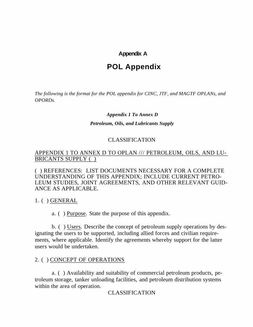
The following is the format for the POL appendix for CINC, JTF, and MAGTF OPLANs, andOPORDs.
Appendix 1 To Annex D
Petroleum, Oils, and Lubricants Supply
CLASSIFICATION
APPENDIX 1 TO ANNEX D TO OPLAN /// PETROLEUM, OILS, AND LU-BRICANTS SUPPLY ( )
( ) REFERENCES: LIST DOCUMENTS NECESSARY FOR A COMPLETE UNDERSTANDING OF THIS APPENDIX; INCLUDE CURRENT PETRO-LEUM STUDIES, JOINT AGREEMENTS, AND OTHER RELEVANT GUID-ANCE AS APPLICABLE.
1. ( ) GENERAL
a. ( ) Purpose. State the purpose of this appendix.
b. ( ) Users. Describe the concept of petroleum supply operations by des-ignating the users to be supported, including allied forces and civilian require-ments, where applicable. Identify the agreements whereby support for the latterusers would be undertaken.
2. ( ) CONCEPT OF OPERATIONS
a. ( ) Availability and suitability of commercial petroleum products, pe-troleum storage, tanker unloading facilities, and petroleum distribution systemswithin the area of operation.
CLASSIFICATION
Appendix A
POL Appendix
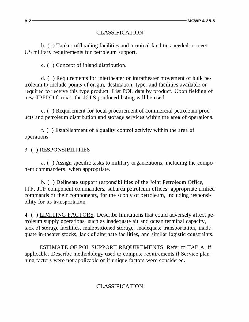
CLASSIFICATION
b. ( ) Tanker offloading facilities and terminal facilities needed to meetUS military requirements for petroleum support.
c. ( ) Concept of inland distribution.
d. ( ) Requirements for intertheater or intratheater movement of bulk pe-troleum to include points of origin, destination, type, and facilities available orrequired to receive this type product. List POL data by product. Upon fielding ofnew TPFDD format, the JOPS produced listing will be used.
e. ( ) Requirement for local procurement of commercial petroleum prod-ucts and petroleum distribution and storage services within the area of operations.
f. ( ) Establishment of a quality control activity within the area ofoperations.
3. ( ) RESPONSIBILITIES
a. ( ) Assign specific tasks to military organizations, including the compo-nent commanders, when appropriate.
b. ( ) Delineate support responsibilities of the Joint Petroleum Office,JTF, JTF component commanders, subarea petroleum offices, appropriate unifiedcommands or their components, for the supply of petroleum, including responsi-bility for its transportation.
4. ( ) LIMITING FACTORS. Describe limitations that could adversely affect pe-troleum supply operations, such as inadequate air and ocean terminal capacity,lack of storage facilities, malpositioned storage, inadequate transportation, inade-quate in-theater stocks, lack of alternate facilities, and similar logistic constraints.
ESTIMATE OF POL SUPPORT REQUIREMENTS. Refer to TAB A, ifapplicable. Describe methodology used to compute requirements if Service plan-ning factors were not applicable or if unique factors were considered.
CLASSIFICATION
A-2 MCWP 4-25.5
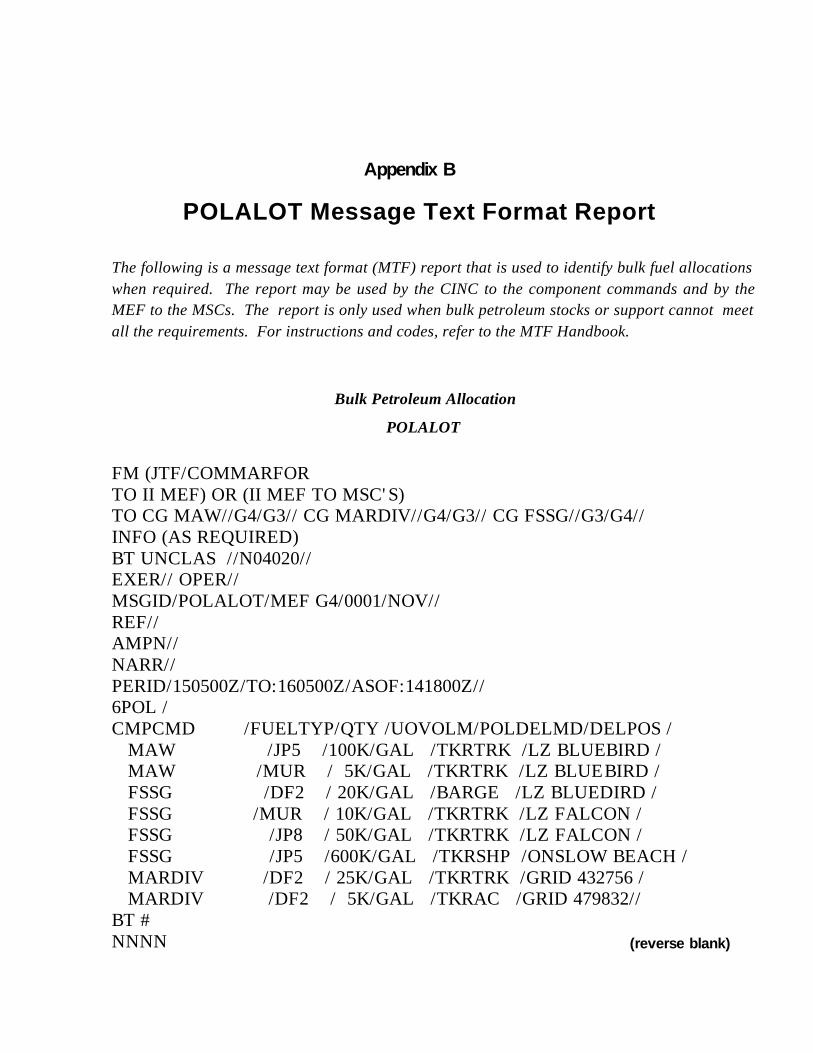
The following is a message text format (MTF) report that is used to identify bulk fuel allocationswhen required. The report may be used by the CINC to the component commands and by theMEF to the MSCs. The report is only used when bulk petroleum stocks or support cannot meetall the requirements. For instructions and codes, refer to the MTF Handbook.
Bulk Petroleum Allocation
POLALOT
FM (JTF/COMMARFOR TO II MEF) OR (II MEF TO MSC'S) TO CG MAW//G4/G3// CG MARDIV//G4/G3// CG FSSG//G3/G4// INFO (AS REQUIRED) BT UNCLAS //N04020// EXER// OPER// MSGID/POLALOT/MEF G4/0001/NOV// REF// AMPN// NARR// PERID/150500Z/TO:160500Z/ASOF:141800Z// 6POL /CMPCMD /FUELTYP/QTY /UOVOLM/POLDELMD/DELPOS / MAW /JP5 /100K/GAL /TKRTRK /LZ BLUEBIRD / MAW /MUR / 5K/GAL /TKRTRK /LZ BLUEBIRD / FSSG /DF2 / 20K/GAL /BARGE /LZ BLUEDIRD / FSSG /MUR / 10K/GAL /TKRTRK /LZ FALCON / FSSG /JP8 / 50K/GAL /TKRTRK /LZ FALCON / FSSG /JP5 /600K/GAL /TKRSHP /ONSLOW BEACH / MARDIV /DF2 / 25K/GAL /TKRTRK /GRID 432756 / MARDIV /DF2 / 5K/GAL /TKRAC /GRID 479832// BT # NNNN
Appendix B
POLALOT Message Text Format Report
(reverse blank)
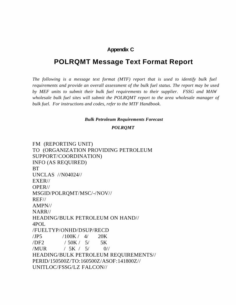
The following is a message text format (MTF) report that is used to identify bulk fuelrequirements and provide an overall assessment of the bulk fuel status. The report may be usedby MEF units to submit their bulk fuel requirements to their supplier. FSSG and MAWwholesale bulk fuel sites will submit the POLRQMT report to the area wholesale manager ofbulk fuel. For instructions and codes, refer to the MTF Handbook.
Bulk Petroleum Requirements Forecast
POLRQMT
FM (REPORTING UNIT) TO (ORGANIZATION PROVIDING PETROLEUMSUPPORT/COORDINATION) INFO (AS REQUIRED) BT UNCLAS //N04024// EXER// OPER// MSGID/POLRQMT/MSC/-/NOV// REF// AMPN// NARR// HEADING/BULK PETROLEUM ON HAND// 4POL /FUELTYP/ONHD/DSUP/RECD /JP5 /100K / 4/ 20K /DF2 / 50K / 5/ 5K /MUR / 5K / 5/ 0// HEADING/BULK PETROLEUM REQUIREMENTS// PERID/150500Z/TO:160500Z/ASOF:141800Z// UNITLOC/FSSG/LZ FALCON//
Appendix C
POLRQMT Message Text Format Report
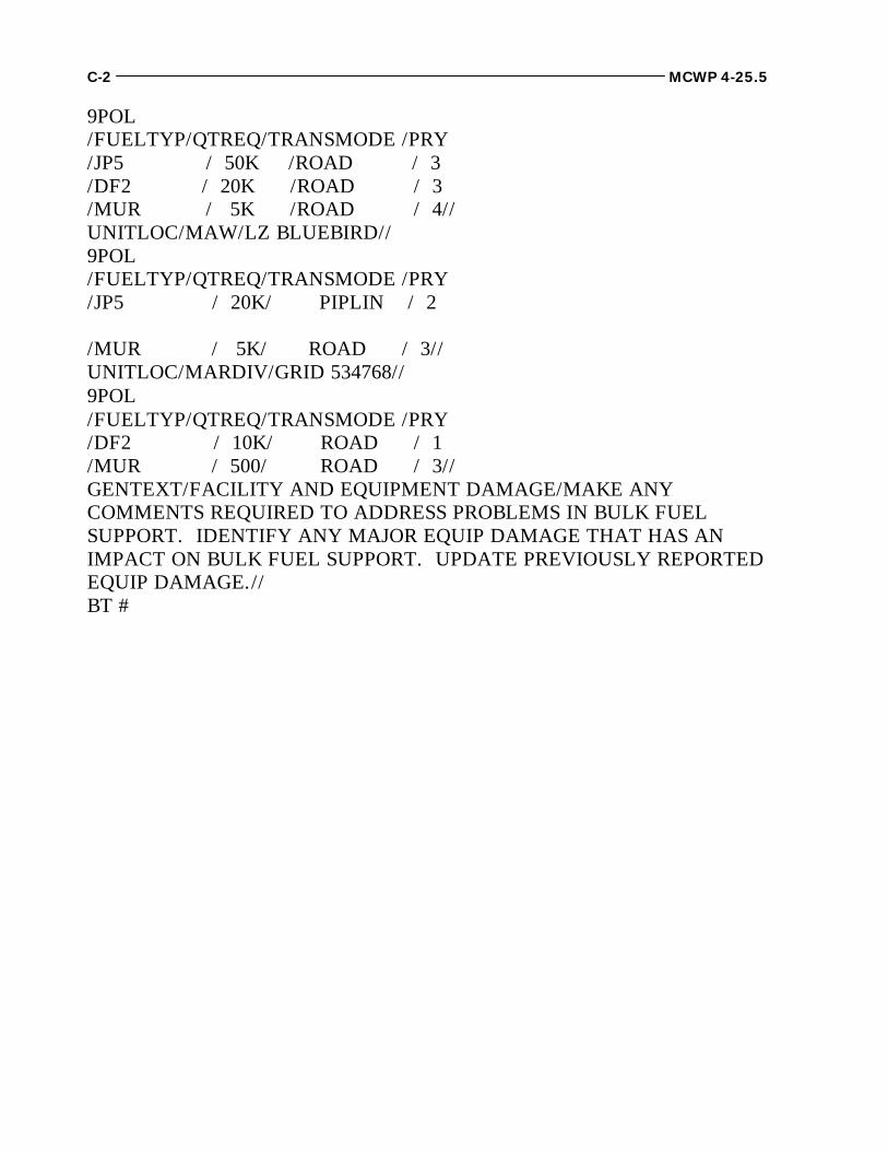
9POL /FUELTYP/QTREQ/TRANSMODE /PRY /JP5 / 50K /ROAD / 3 /DF2 / 20K /ROAD / 3 /MUR / 5K /ROAD / 4// UNITLOC/MAW/LZ BLUEBIRD// 9POL /FUELTYP/QTREQ/TRANSMODE /PRY /JP5 / 20K/ PIPLIN / 2
/MUR / 5K/ ROAD / 3// UNITLOC/MARDIV/GRID 534768// 9POL /FUELTYP/QTREQ/TRANSMODE /PRY /DF2 / 10K/ ROAD / 1 /MUR / 500/ ROAD / 3// GENTEXT/FACILITY AND EQUIPMENT DAMAGE/MAKE ANYCOMMENTS REQUIRED TO ADDRESS PROBLEMS IN BULK FUELSUPPORT. IDENTIFY ANY MAJOR EQUIP DAMAGE THAT HAS ANIMPACT ON BULK FUEL SUPPORT. UPDATE PREVIOUSLY REPORTEDEQUIP DAMAGE.// BT #
C-2 MCWP 4-25.5
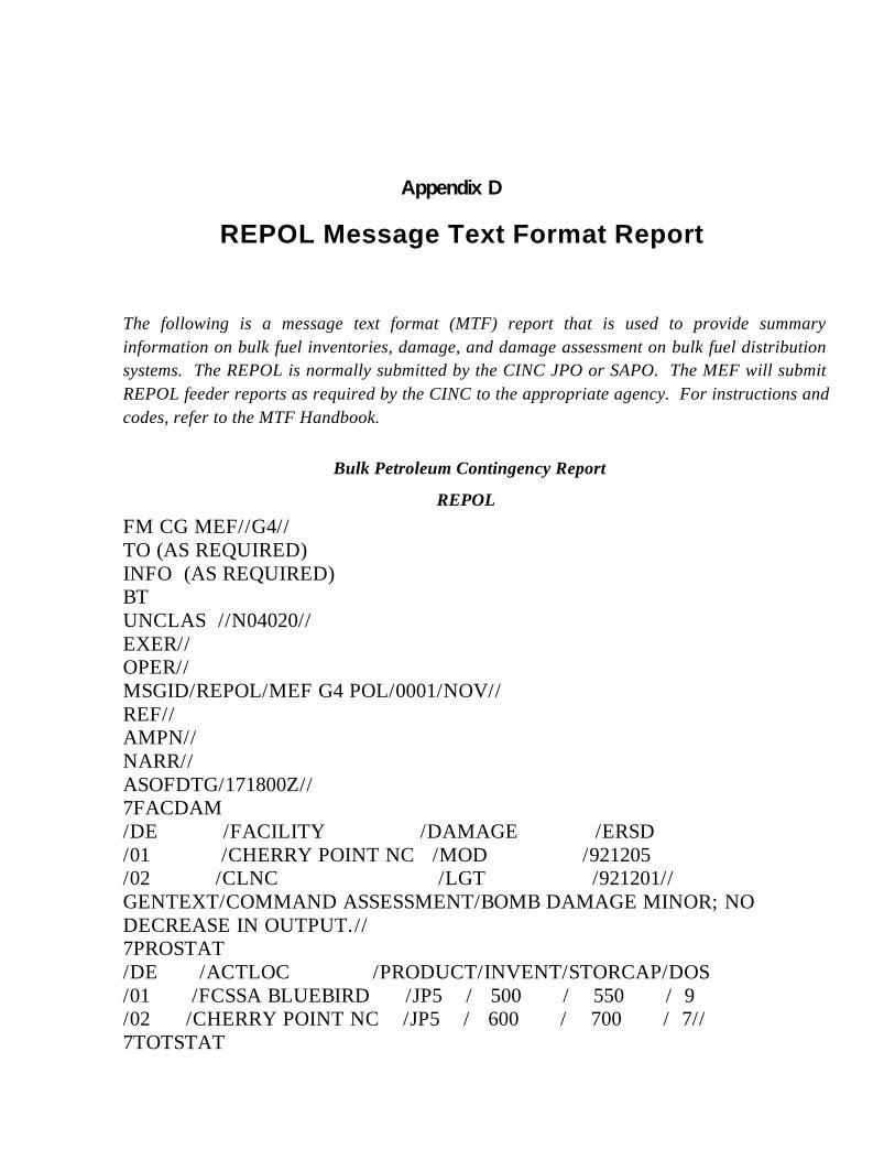
The following is a message text format (MTF) report that is used to provide summaryinformation on bulk fuel inventories, damage, and damage assessment on bulk fuel distributionsystems. The REPOL is normally submitted by the CINC JPO or SAPO. The MEF will submitREPOL feeder reports as required by the CINC to the appropriate agency. For instructions andcodes, refer to the MTF Handbook.
Bulk Petroleum Contingency Report
REPOLFM CG MEF//G4// TO (AS REQUIRED) INFO (AS REQUIRED) BT UNCLAS //N04020// EXER// OPER// MSGID/REPOL/MEF G4 POL/0001/NOV// REF// AMPN// NARR// ASOFDTG/171800Z// 7FACDAM /DE /FACILITY /DAMAGE /ERSD /01 /CHERRY POINT NC /MOD /921205 /02 /CLNC /LGT /921201// GENTEXT/COMMAND ASSESSMENT/BOMB DAMAGE MINOR; NODECREASE IN OUTPUT.// 7PROSTAT /DE /ACTLOC /PRODUCT/INVENT/STORCAP/DOS /01 /FCSSA BLUEBIRD /JP5 / 500 / 550 / 9 /02 /CHERRY POINT NC /JP5 / 600 / 700 / 7// 7TOTSTAT
Appendix D
REPOL Message Text Format Report

/PRODUCT /INVENT /STORCAP /DOS /JP5 / 1100 / 1250 / 16// 7DEFSTAT /DE /PORT /PRODUCT/QUANTITY /PERREQ /01 /CHERRY POINT NC /JP5 / 1000 /1-DEC// GENTEXT/GENERAL SUMMARY/FREE TEXT.__________// BT #
D-2 MCWP 4-25.5
1. Clean Water Act
The Clean Water Act requires state and federal regulatorsto enter into programs designed to prevent, reduce, oreliminate pollution of navigable waters of the UnitedStates. The Water Quality Improvement Act of 1974 gov-erns the discharge of oil into navigable waters. On Decem-ber 11, 1973, the Environmental Protection Agency (EPA)published regulations to prevent pollution of U.S. watersby oil coming from onshore and offshore facilities not re-lated to transportation. These regulations are identified inTitle 40, Code of Federal Regulations, Part 112 (40 CFR,Part 112), and became effective on January 10, 1974.
2. Oil Pollution Act of 1990
The Oil Pollution Act of 1990 (OPA) consolidates andchanges existing laws which govern prevention, oil spillliability, and preparedness and cleanup. The law affectspipelines, vessels, oil rigs, piers and terminals (on shore)that transport, handle, or store crude oil and petroleumproducts. Many new and important provisions that will af-fect the DOD fuel facilities are contained in the act, includ-ing increased liability for oil spills, more comprehensiveoil spill contingency plans, training and drill requirements,better response capability and tougher enforcement. Addi-tionally, the OPA has strengthened the role of three sepa-rate federal agencies: The U.S. Coast Guard (USCG), theEPA and the U.S. Department of Transportation [Re-search and Special Programs Administration (RSPA)].
3. Spill Prevention Control and Countermeasure Plan
The spill prevention control and countermeasure plan(SPCCP) is designed to help prevent the discharge of oil.A spill contingency plan is developed based on guidancefrom the commander or the local base commander and theEnvironmental Protection Agency. An outline of a typicalcontingency plan is provided in figure E-1. The plan ad-dresses responsibilities and procedures for containing andcleaning up spills. The following items must be addressedin the SPCCP:
Oil is defined as petroleum products, includinggasoline, kerosene, jet fuel, fuel oil, sludge, oilrefuse, and oil mixed with wastes other thandredged soil.
An SPCCP is valid for 3 years, if no changes aremade to the plan or the facility.
Coast Guard, EPA, or RSPA approval isrequired.
"Worst Case" scenario must be addressed.
Response capability must be documented.
EPA Regional Administrator must be notified ofspills in accordance with local SOPs.
The SPCCP and facility Spill Response Plan mustbe available for inspection at the facility.
Appendix E
Environmental Regulations
Compliance with environmental laws and pollution control standards is necessarywithin the U.S. and its territories. MCO P11000.8B provides policy for complyingwith the existing laws and regulations. At bulk fuel facilities, the major area of en-vironmental concern centers on the handling and storage of petroleum products.There are several environmental requirements which relate directly to fuel opera-tions and facilities. All bulk fuel personnel shall be familiar with reporting require-ments, equipment, and training needs that support environmental concerns.

The appropriate regulatory agency must be noti-fied in the event of a spill.
Figure E-1. Outline of a Typical Contingency Plan.
Regulations require the preparation and implementation ofa SPCCP for all non-transportation related facilities whichhave discharged, or could reasonably discharge, oil intoU.S. navigable waters, or the adjoining shorelines. The
SPCCP must also be reviewed and certified by a registeredprofessional engineer (PE) for oil storage facilities with atotal aboveground storage capacity of more than 1,320 gal-lons, or an underground storage capacity of 42,000 gallonsor more, and located on or near navigable waters (whichis almost any body of water or continuous stream).
If a spill occurs, the appropriate EPA Regional Adminis-trator will be given the following information in accor-dance with local SOPs:
Name of facility.
Name(s) of the owner or operator of the facility.
Location of the facility.
Date and year of initial facility operation.
Maximum storage or handling capacity of the fa-cility and normal daily throughput.
Description of the facility, including maps, flowdiagrams, and topographic maps.
A complete copy of the SPCCP with any amend-ments.
The cause(s) of such spills(s), including a failureanalysis of the system or subsystem in which thefailure occurred.
The corrective actions and countermeasures taken,including an adequate description of equipmentrepairs and/or replacements, and the cost in-volved.
Additional preventive measures taken or contem-plated to reduce the possibility of recurrence.
Other information, as the Regional Administratormay reasonably require, pertinent to the plan orspill event.
4. Emergency Response Actions
Other federal and state regulations exist which prohibit thedischarge of petroleum products into the environment
E-2 MCWP 4-25.5
Oil Spill Contingency Plan Outline
I. BACKGROUND
a. Inventory of petroleum products handled.b. Identification of most likely areas where a spill could occur.c. Types of operations which could result in a spill.d. Location of biological, recreational, or other sensitive areas.e. Spill responsibilities assigned by the local commander and EPA.f. Inventory and location of spill clean-up equipment and materials.
II. SPILL PLAN(S)
a. Spill reporting procedures.b. Telephone numbers for key points of contact and fire department.c. Spill containment and clean-up procedures for possi- ble scenarios including personnel resources require- ments.
(1) Type of product spilled.(2) Size of spill.(3) Location of spill.(4) Time of spill.(5) Weather conditions.
d. Disposal procedures for product and clean-up materials.e. Public affairs coordination.
III. SUPPORT
a. Procedures for obtaining spill equipment and material.b. Spill equipment maintenance program.c. Training.d. Contacts for specialized assistance.
(such as soil, ground water, and surface waters). If a spilloccurs, the following steps must be taken immediately:
Step One. Stop the Spill. Prevent a further release offuel to the environment by shutting off valves in a leakingpipeline, removing product from a leaking storage vessel,etc.
Step Two. Contain the Spill. To contain spill, con-struct berms around the area, use absorbent materials tosoak up the spill, use containment boom on surface waterspills, excavate cut-off trenches, etc. For handling JP-4 andother volatile fuel spills on water, divert and contain thefuel away from structures and try to remediate as soon as
at government fuel facilities are ignitable, there should beno smoking, open flames, or equipment with magneto-sparked engines, catalytic converters, or equipment whichmight otherwise produce sparks or static electricity in thevicinity of the spill site. Also, many fuels can cause skinirritation, dizziness, fainting, or even death, and thereforeshould be handled with caution.
Step Three. Report the Spill. Personal safety is moreimportant than environmental protection. If there is a threatto life or health, the local fire department should be thefirst official agency notified. As soon as feasible and within24 hours after the spill, the appropriate regulatory agencymust be notified. A list of agencies and phone numbers forreporting various types of spills should be included in allexercise plans and LOIs. Information that may be re-quested when the spill is reported is included in figureA-2. To protect a downstream public or water supply inthe event of a spill, call the appropriate public works de-partment or plant manager to have them shut down the in-take valves . Report spills into or upon the navigablewaters of the United States or adjoining shores to U.S.Coast Guard, Washington, D.C. National Response Cen-ter (NRC), 24 - hour (800) 424-8802 or (202) 267-2675.See figure E-2 for spill reporting information.
Step Four. Clean Up the Spill. After stopping andcontaining the spill, recover the spilled product and reme-diate the impacted soil, ground water, and/or surface wa-ter. Because Government fuel facilities often do not havethe necessary equipment, resources, or experience to as-sess and remediate the impacted areas, obtain a spill re-sponse contractor through the Defense Fuel Region asquickly as possible to expedite the cleanup in order to re-duce the spread of contamination.
Step Five. Notify the Defense Fuel Region . Oncethe Defense Fuel Region has been notified of the spill, theywill notify DFSC which will then make arrangements tohave a remediation contractor brought on site, if needed.Regional contracts have been set up through DFSC to ex-pedite the remediation process for DFSC facilities. Underthe terms of the contracts, the remediation contractor musthave a knowledgeable project manager on site within 24hours of being notified. The facility Quality SurveillanceRepresentative, the facility engineer, or POL officershould cooperate with the environmental contractor in pro-viding any information requested to expedite the cleanupprocess.
5. Assessment and Remediation
In the petroleum industry, the strategy for a comprehen-sive assessment and remediation is straightforward—thequicker the cleanup, the less the spread of contaminants.Therefore, assessment activities should be completed in atimely manner so that a remediation system may be de-signed and installed before significant migration of thecontaminant plume occurs. Before remediating a site, thevertical and horizontal extent of contamination must bedefined.
a. The Defining Method. The defining method useddepends on the type of spill. For a surface spill, themethod for defining the extent of contamination is by vis-ual inspection and shallow soil sampling. For a subsurfacespill, the method for defining the extent of contaminationis through the installation of ground water monitoringwells.
b. Corrective Action. The cleanup of a subsurfacespill can be a very slow, time-consuming process; there-fore, long-term (several years) monitoring and operation ofthe remedial action system will likely be required. Oncethe extent of the contamination has been defined, morecorrective action technologies can be selected and imple-mented. The type of technology selected is based on site-specific information, such as—
Volatility of the spilled product
Type of media impacted (clay soil, sands, surfacewater, or ground water)
Size of contaminant plume
Bulk Liquids Operations E-3

Cleanup goals
6. Preventive Booming Policy
DFSC practices preventive booming whenever state or lo-cal regulations dictate and according to the followingguidance:
E-4 MCWP 4-25.5
Figure E-2. Spill Reporting Information.
SPILL REPORTING INFORMATION
Spill discovery time: _______________________ Date: ___________________________________________
Weather conditions/sea state: ________________________________________________________________
Material spilled: ______________________________________________________________________________
Amount spilled: ______________________________________________________________________________
Size of slick/area affected: ____________________________________________________________________
Location and source of spill: __________________________________________________________________
Environmental damage/nearby freshwater terrain: ______________________________________________
Cause/circumstance of spill: __________________________________________________________________
Existing/potential hazards (fire, explosions): ____________________________________________________
Personal injuries or fatalities: __________________________________________________________________
Corrective action being taken/timetable for control, contain, cleanup: ____________________________
______________________________________________________________________________________________
Any other unique/unusual circumstances: ______________________________________________________
______________________________________________________________________________________________
______________________________________________________________________________________________
______________________________________________________________________________________________
Name, address, phone number of person who discovered spill: __________________________________
______________________________________________________________________________________________
Name of supervisor/manager in charge: ________________________________________________________
Contacts:
Agency Date Time Person
______________________________________________________________________________________________
______________________________________________________________________________________________
______________________________________________________________________________________________
______________________________________________________________________________________________
Transfers of nonpersistent fuels such as JP-4 andgasoline must not be boomed unless ordered bythe Coast Guard.
Fixed boom will not be required in the areas ofswift current (1.5 knots or greater) when fuel willbe deflected over the top or under the boom.
Do not boom in situations deemed unsafe.
a. California. The state of California implemented apreventive booming regulation on November 21, 1992 andbegan enforcement on December 21, 1992. The state hasconcluded that most spills occur during bunkering opera-tions; however, a significant amount of fuel is spilled inCalifornia waters during loading and unloading operationsfrom tankers and naval oilers. The state further determinedthat preventive booming is good environmental policy tocontain such spills and should be exercised to the greatestextent practicable. Thus, the state regulation requires aboom to be deployed, prior to initiating a fuel transfer, toencircle the vessel in order to contain any fuel spilled intothe water. Now, terminals must either contract for thebooming services or provide the manpower to deploy andretrieve boom during fuel transfer operations. Preventivebooming is not required at DOD facilities in situationsdeemed unsafe or where impractical or ineffective. Preven-tive booming is not required in the following situations:
Nonresistant fuels, such as JP-4 and gasolineshould not be boomed due to the presence of ex-plosive vapor. In this case, dispersion is the bestsolution as it allows the fuel to evaporate. Onlypersistent POL products (heavy ends and rela-tively high flash points) must be boomed.
Fixed boom will not be required for marinetransfer operations where the current is greaterthan or equal to 1.5 knots for at least 180 days ofthe year. Fixed boom will not effectively containspills in such areas; the fuel will slide under orover the top of the boom.
The state requires trained personnel standing byin a boat with adequate boom ready to deploy.
b. Other States. Until California implemented a pre-ventive booming regulation, it was only a matter of localpolicy whether to boom. California perceived that spillsoccur most often in fuel bunkering operations. However,preventive booming during all pier fuel transfer operations,when practical and safe, provides an added measure of as-surance. Spills which are immediately contained in a con-gested harbor are easier to clean up and they provide foraccurate identification of the spiller. Although preventivebooming is required for transfer involving persistent prod-ucts (crude and heavy oils) in Alaska and is proposed forMaine, there is no requirement to boom light grade fuelsin any other state. The requirement for preventive boom-ing, which affects marine fuels transfer operations at wharfor pier facilities throughout the state of California, may beunder consideration for adoption by the EPA, the CoastGuard, and other states.
Bulk Liquids Operations E-5
(reverse blank)

AABFS ........amphibious assault bulk fuel systemAAFS ..............amphibious assault fuel systemABFDS ............ aerial bulk fuel delivery systemACE ...................... aviation combat elementAE ................................ assault echelonAFFF ................. aqueous film-forming foamAFOE ................... assault follow-on echelonALOC ................. air lines of communicationsAMC ......................Air Mobility CommandAO ..............................area of operationsAO ........... United States Ship, Auxiliary, OilerAOA ....................amphibious objective areaAOG ............... United States Ship, Auxiliary,
Oiler, GasolineAOR ........................ area of responsibilityAPI .................. American Petroleum InstituteASTM ...........American Society for Testing and Materials
BDA .................... bomb damage assessmentBIU ........................... beach interface unitBPWRR ............... bulk petroleum war reserve requirementsBPWRS ........ bulk petroleum war reserve stocksB/2 ........... anti-icing additive refractometer and
test kit
CAS .............................. close air supportCE ............................. command elementCFD .................... contaminated fuel detectorCFR .................... code of federal regulationsCINC ..........................commander in chiefCOMMARFOR ...... Commander, Marine ForcesCOMMZ .................... communications zoneCONUS ..................continental United StatesCSS ....................... combat service support
CSSD ......... combat service support detachmentCSSE .............. combat service support elementDFAMS ....................defense fuel automated managementsystemDFR ........................... defense fuel regionDFSC ...................defense fuel supply centerDFSP ....................defense fuel support pointDLA ................... Defense Logistics AgencyDOD ...................... Department of DefenseDOS .............................. day(s) of supplyDRMO .... Defense Reutilization Marketing OfficeDS ..................................direct support
EAF ......................... expeditionary airfieldEOB ......................... enemy order of battleEPA .............Environmental Protection AgencyERS .................... expedient refueling systemESBn ....................engineer support battalionEUCOM ...................... European Command
FARP ......... forward arming and refueling pointFAWPSS ......... forward area water point supply supportsystemFEBA .............. forward edge of the battle areaFMFM ................ Fleet Marine Force manualFOB ................................. free on boardFSII .................... fuel system icing inhibitorFSSA .................... force service support areaFSSG .................. force service support groupFWPCA .........federal water pollution control act
GCE ....................... ground combat elementgph ............................... gallons per hourgpm ............................ gallons per minuteGS ................................ general support
Appendix F
Glossary
I. Acronyms

HERS ....... helicopter expedient refueling systemHN .................................... host nationHNS ........................... host nation supportHQMC .........Headquarters, U. S. Marine Corps
IDF ................................. item data fileIMM ..................integrated material managerIMP ................... inventory management planIPDS ........... inland petroleum discharge systemISO ............
JCS ........................... Joint Chiefs of StaffJLOTS ............... joint logistics over the shoreJOPS .............. joint operation planning systemJP ................. aviation fuel, “jet propulsion.”JPO ......................... joint petroleum officeJTF ................................ joint task force
LAPES ... low-altitude parachute extraction systemLCU .......................... landing craft utilityLFORM ......... landing forces operational reserve mate-rial LMIS logistics management information systemLOC ...................... lines of communications
MAGTF ..............Marine air-ground task forceMARDIV ..........................Marine divisionMARFOR .......................... Marine forcesMAW ........................Marine aircraft wingMCAS .................... Marine Corps air stationMCB .......................... Marine Corps baseMCO ......................... Marine Corps OrderMEB ................ Marine expeditionary brigadeMEF .................. Marine expeditionary forceMEU ................... Marine expeditionary unitMIPR ..................military inter-departmental
purchase requestMILHDBK ..................... military handbookMK-I .......... free water detector kit, older modelMK-II ........ free water detector kit, newer modelMK-III ...... solid contaminant detector kit, newer model MK-IIIsMoGas ........................automotive gasolineMOS ............... military occupational specialtyMOU .............. memorandum of understandingMPF ................ maritime prepositioning forceMPS ................. maritme prepositioning shipsMPSRON ...........maritime prepositioning ships
squadronMSC ................... Military Sealift CommandMTBn ....................motor transport battalionMTF ......................... message text formatMWSG ................ Marine wing support groupMWSS .............Marine wing support squadron
NAVAIR .................................naval airNAVPET ................... Navy petroleum officeNBC ............ nuclear, biological, and chemicalNCF ...................... naval construction forceNOB ......................... naval order of battleNRC ..................... national response centerNSF .............................. Navy stock fund
O&M MC ...... operation and maintenance Marine CorpsO&MN ........... operation and maintenance NavyOPA ...............................oil pollution actOPDS ....... off-shore petroleum discharge systemOPLAN ............................ operation planOPORD ........................... operation orderOPSEC .........................operations securityOSD ............ Office of the Secretary of Defense
PACOM .........................Pacific CommandPM ........................ preventive maintenancePOL ................ petroleum, oils, and lubricantsPOLALOT ................... petroleum allocationPOLRQMT ................. petroleum requirementPOS ......................primary operating stocksPurple K .... chemical firefighting agent; potassium bicarbonate
QA .............................. quality assuranceQS ............................ quality surveillance
RCZ ............................. rear combat zoneREPOL ......... bulk petroleum contingency reportROWPU ........ reverse osmosis water purification unit RSPA .......... research and special programs administration
SALM .................. single anchor leg mooringSAPO .................sub-area petroleum office(r)
F-2 MCWP 4-25.5

SCP .......................... service control pointSIXCONs .................. six containers togetherSLWT ................... side loadable warping tugSNCOIC ........ staff noncommissioned officer-in- charge SOP .......... standing operating procedureSPCCP ................ spill prevention control and countermeasuresplanSTOVL .......... short takeoff and vertical landingSWA .............................. Southwest Asia
TACOPS ....................... tactical operationsTAFDS ..... tactical airfield fuel dispensing systemTAM .................. table of authorized materialTAMCN ....... table of authorized material control num-ber TAMMC . Theater Army Material Management Com-mand TAU ........................ twin agent unitTBFDS ....... tactical bulk fuel distribution systemTDS ..........................total dissolved solidsT/E ............................. table of equipment
TFS .......................... tactical fuel systemsTPLM ...... tactical petroleum laboratory, mediumTPTs .................. tactical petroleum terminalsTWDS ............tactical water distribution system
USAPC .............. U.S. Army Petroleum CenterUSCG ..........................U. S. Coast GuardUSMTF ....... United States Message Text Format
WQAK .................. water quality analysis kitWSIM .......... water separometer index modified
Bulk Liquids Operations F-3

A
additive - An agent used for improving existingcharacteristics or for imparting new characteristicsto certain petroleum products.
aerial refueling - The use of aerial tanker config-ured aircraft to provide refueling service to helicop-ters, fixed-wing, and tilt-rotor aircraft in flight.Aerial refueling extends the range, time on station,mobility, and flexibility of MAGTF aircraft.(FMFRP 0-14)
American Petroleum Institute (API) - The instituterepresents and is supported by the petroleum indus-try. It standardizes the tools and equipment used bythe industry and promotes the advancement of re-search in the petroleum field. (FM 10-70-1)
American Society for Testing and Materials(ASTM) - A national scientific and technical organi-zation formed for the development of standards orcharacteristics and performance of materials, prod-ucts, systems, and services and the promotion of re-lated knowledge.
amphibious assault bulk fuel system - The U. S.Navy system of flexible, buoyant hose used to effectship-to-shore transfer of fuels. Five thousand feet of6-inch hose connects amphibious shipping to shore-based fuel storage systems located at the high watermark. (FMFRP 0-14)
amphibious assault fuel system - The MarineCorps’ primary fuel storage system used to supportamphibious operations. This system is composed ofa number of components capable of receiving, trans-ferring, and dispensing mogas, diesel, or aviationfuels. The system can be set up in a wide variety ofconfigurations to meet varying operational require-ments. (FMFRP 0-14)
amphibious objective area - A geographical area,delineated in the initiating directive, for purposes ofcommand and control within which is located theobjective(s) to be secured by the amphibious taskforce. This area must be of sufficient size to ensure
accomplishment of the amphibious task force’s mis-sion and must provide sufficient area for conductingnecessary sea, air, and land operations. (Joint Pub1-02)
api gravity - An arbitrary scale expressing the grav-ity or density of liquid petroleum products. Themeasuring scale is calibrated in terms of degreesAPI. The gravity of any petroleum product is cor-rected to 60 degrees F.
appearance - Refers to the visual examination of fu-els. The terms used to describe appearance are clearand bright, hazy and cloudy. (FM 10-70-1)
B
barrel (bbl.) - A common unit of measurement ofliquids in the petroleum industry. It equals 42 U.S.gallons.
berm - An earthen wall constructed around a fueltank to contain potential fuel leaks or spills.
berm liner - A cloth or plastic tarp, impervious tofuel, used to line a berm.
blending - Mixing on-specification fuel with off-specification fuel to bring the latter to specificationor use limits. Used as a method of reclamation.
bonding - Making an electrical connection betweenitems of equipment/tanks. Bonding equalizes electri-cal potential between items, and reduces the threat ofsparks due to static electricity passing between theitems of equipment.
bottom sediment and water - Amount of sedimentand water in the bottom of fuel tanks.
bulk fuel company - A unit that performs all func-tions incident to the supply of class III and class III(A) to elements of a MAGTF, to include distributionto, but not within, air bases during an amphibiousassault and subsequent operations ashore; to ensurethat class III (A) products distributed to supported
F-4 MCWP 4-25.5
II. Definitions
air elements are of the required type, quality, andpurity. (FMFRP 0-14)
bulk liquid - Fuel or water itself, not inclusive ofthe container or handling apparatus. A term alsoused to define quantities of fuel or water above ei-ther 55 gallons or 250/500 gallons; the former whenhandling product in 55-gallon metal drums is com-mon, the latter when 250/500- gallon collapsible wa-ter drums or 500-gallon collapsible fuel drums are inuse.
bulk petroleum product - Those petroleum prod-ucts (fuels, lubricants) which are normally trans-ported by pipeline, rail tank car, tank truck, barge,or tanker and stored in tanks or containers having acapacity of more than 55 gallons, except fuels in500-gallon collapsible containers, which are consid-ered to be packaged. (FM 10-70-1)
C
carbon dioxide - A heavy, colorless gas, CO2,which will not support combustion (therefore beinguseful as a fire-extinguishing agent).
carbon monoxide - A colorless, odorless, and poi-sonous gas, CO, resulting from the incomplete com-bustion of carbon.
centrifuge - A whirling instrument for separatingliquids or liquids and solids of different specificgravity by use of centrifugal force.
class III - Petroleum products, POL (petroleum, oilsand lubricants), often broken down into class IIIAfor aviation fuel, and class III(W) for ground equip-ment fuel.
combat service support detachment - A separatetask organization of combat service support assetsformed for the purpose of providing rearming,refueling, and/or repair capabilities to the Marineair-ground task force or designated subordinate ele-ments; e.g., a battalion conducting independent op-erations or an aircraft squadron operating at aremote airfield. The combat service support elementnormally provides the command element of a com-bat service support detachment. (FMFRP 0-14)
contaminant - A foreign substance in a product.
D
defense fuel supply center (DFSC) - An activityunder the Defense Logistics Agency (DLA) with theresponsibility as the integrated material manager(IMM) for wholesale bulk petroleum products untiltheir delivery to the point of sale. This responsibilityincludes contract administration in an oversee area.(FM 10-70-1)
defense fuel supply point (DFSP) - Any military orcommercial bulk fuel terminal storing productsowned by DLA. (FM 10-70-1)
Defense Logistics Agency (DLA) - The agency, atthe Department of Defense level, charged with pro-viding the most effective and economical support ofcommon supplies and services to the Military De-partments and other designated Department of De-fense components. It is the agency under whichDFSC operates. (FM 10-70-1)
drum - Either 16- or 18-gage steel cylindrical con-tainers (generally, 55-gallon size) or 250/500- galloncollapsible water containers/500-gallon collapsiblefuel containers.
F
flash point - The temperature at which a fuel will“flash” when exposed to test flame — flame diame-ter of approximately 1/8 inch, like a butane lighterflame adjusted as low as possible; also a test per-formed per ASTM.
force service support group - The combat servicesupport element of the Marine expeditionary force(MEF). It is a permanently organized Fleet MarineForce command charged with providing combat ser-vice support beyond the organic capabilities of sup-ported units of the MEF. If supporting a force offorce of greater size, additional assets arenecessaryto augment its capabilities. Although permanentlystructured with eight functional battalions, task or-ganizations from those battalions would normally
Bulk Liquids Operations F-5
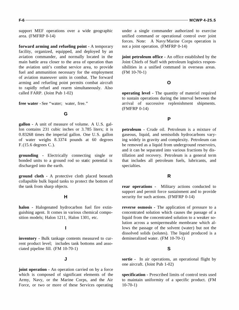
support MEF operations over a wide geographicarea. (FMFRP 0-14)
forward arming and refueling point - A temporaryfacility, organized, equipped, and deployed by anaviation commander, and normally located in themain battle area closer to the area of operation thanthe aviation unit’s combat service area, to providefuel and ammunition necessary for the employmentof aviation maneuver units in combat. The forwardarming and refueling point permits combat aircraftto rapidly refuel and rearm simultaneously. Alsocalled FARP. (Joint Pub 1-02)
free water - See “water; water, free.”
G
gallon - A unit of measure of volume. A U.S. gal-lon contains 231 cubic inches or 3.785 liters; it is0.83268 times the imperial gallon. One U.S. gallonof water weighs 8.3374 pounds at 60 degreesF.(15.6 degrees C.).
grounding - Electrically connecting single orbonded units to a ground rod so static potential isdischarged into the earth.
ground cloth - A protective cloth placed beneathcollapsible bulk liquid tanks to protect the bottom ofthe tank from sharp objects.
H
halon - Halogenated hydrocarbon fuel fire extin-guishing agent. It comes in various chemical compo-sition models; Halon 1211, Halon 1301, etc.
I
inventory - Bulk tankage contents measured to cur-rent product level; includes tank bottoms and asso-ciated pipeline fill. (FM 10-70-1)
J
joint operation - An operation carried on by a forcewhich is composed of significant elements of theArmy, Navy, or the Marine Corps, and the AirForce, or two or more of these Services operating
under a single commander authorized to exerciseunified command or operational control over jointforces. Note: A Navy/Marine Corps operation isnot a joint operation. (FMFRP 0-14)
joint petroleum office - An office established by theJoint Chiefs of Staff with petroleum logistics respon-sibilities in a unified command in overseas areas.(FM 10-70-1)
O
operating level - The quantity of materiel requiredto sustain operations during the interval between thearrival of successive replenishment shipments.(FMFRP 0-14)
P
petroleum - Crude oil. Petroleum is a mixture ofgaseous, liquid, and semisolids hydrocarbons vary-ing widely in gravity and complexity. Petroleum canbe removed as a liquid from underground reservoirs,and it can be separated into various fractions by dis-tillation and recovery. Petroleum is a general termthat includes all petroleum fuels, lubricants, andspecialties.
R
rear operations - Military actions conducted tosupport and permit force sustainment and to providesecurity for such actions. (FMFRP 0-14)
reverse osmosis - The application of pressure to aconcentrated solution which causes the passage of aliquid from the concentrated solution to a weaker so-lution across a semipermeable membrane which al-lows the passage of the solvent (water) but not thedissolved solids (solutes). The liquid produced is ademineralized water. (FM 10-70-1)
S
sortie - In air operations, an operational flight byone aircraft. (Joint Pub 1-02)
specification - Prescribed limits of control tests usedto maintain uniformity of a specific product. (FM10-70-1)
F-6 MCWP 4-25.5
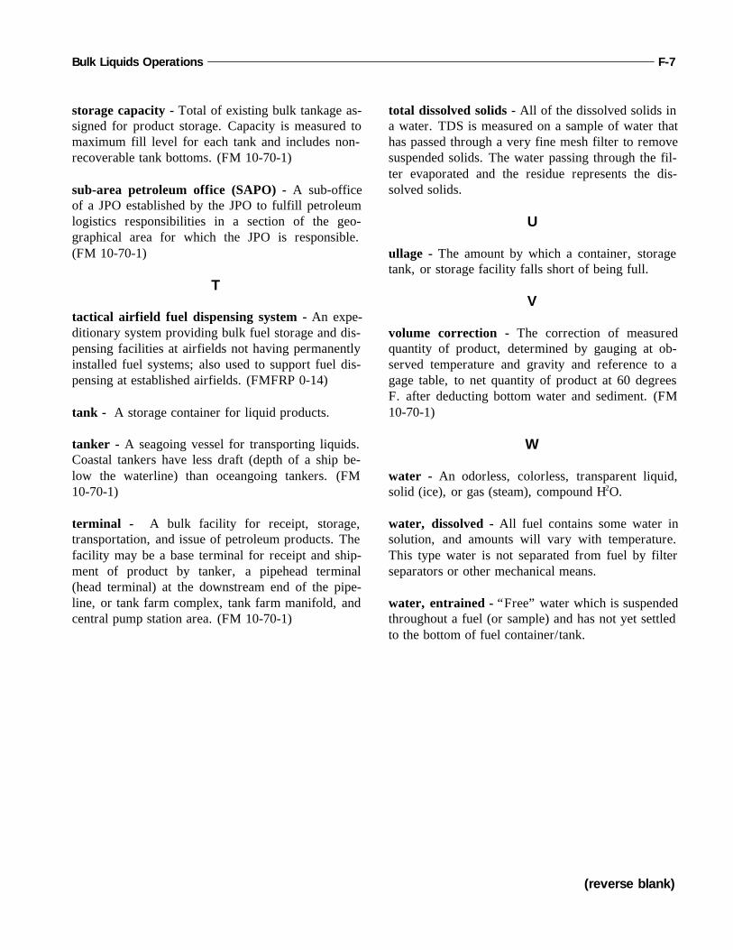
storage capacity - Total of existing bulk tankage as-signed for product storage. Capacity is measured tomaximum fill level for each tank and includes non-recoverable tank bottoms. (FM 10-70-1)
sub-area petroleum office (SAPO) - A sub-officeof a JPO established by the JPO to fulfill petroleumlogistics responsibilities in a section of the geo-graphical area for which the JPO is responsible.(FM 10-70-1)
T
tactical airfield fuel dispensing system - An expe-ditionary system providing bulk fuel storage and dis-pensing facilities at airfields not having permanentlyinstalled fuel systems; also used to support fuel dis-pensing at established airfields. (FMFRP 0-14)
tank - A storage container for liquid products.
tanker - A seagoing vessel for transporting liquids.Coastal tankers have less draft (depth of a ship be-low the waterline) than oceangoing tankers. (FM10-70-1)
terminal - A bulk facility for receipt, storage,transportation, and issue of petroleum products. Thefacility may be a base terminal for receipt and ship-ment of product by tanker, a pipehead terminal(head terminal) at the downstream end of the pipe-line, or tank farm complex, tank farm manifold, andcentral pump station area. (FM 10-70-1)
total dissolved solids - All of the dissolved solids ina water. TDS is measured on a sample of water thathas passed through a very fine mesh filter to removesuspended solids. The water passing through the fil-ter evaporated and the residue represents the dis-solved solids.
U
ullage - The amount by which a container, storagetank, or storage facility falls short of being full.
V
volume correction - The correction of measuredquantity of product, determined by gauging at ob-served temperature and gravity and reference to agage table, to net quantity of product at 60 degreesF. after deducting bottom water and sediment. (FM10-70-1)
W
water - An odorless, colorless, transparent liquid,solid (ice), or gas (steam), compound H2O.
water, dissolved - All fuel contains some water insolution, and amounts will vary with temperature.This type water is not separated from fuel by filterseparators or other mechanical means.
water, entrained - “Free” water which is suspendedthroughout a fuel (or sample) and has not yet settledto the bottom of fuel container/tank.
Bulk Liquids Operations F-7
(reverse blank)
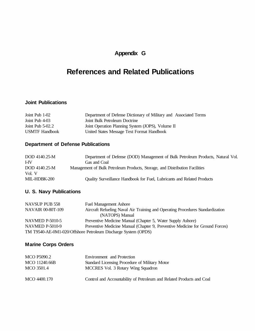
Joint Publications
Joint Pub 1-02 Department of Defense Dictionary of Military and Associated TermsJoint Pub 4-03 Joint Bulk Petroleum DoctrineJoint Pub 5-02.2 Joint Operation Planning System (JOPS), Volume II USMTF Handbook United States Message Text Format Handbook
Department of Defense Publications
DOD 4140.25-M Department of Defense (DOD) Management of Bulk Petroleum Products, Natural Vol.I-IV Gas and CoalDOD 4140.25-M Management of Bulk Petroleum Products, Storage, and Distribution FacilitiesVol. VMIL-HDBK-200 Quality Surveillance Handbook for Fuel, Lubricants and Related Products
U. S. Navy Publications
NAVSUP PUB 558 Fuel Management AshoreNAVAIR 00-80T-109 Aircraft Refueling Naval Air Training and Operating Procedures Standardization
(NATOPS) ManualNAVMED P-5010-5 Preventive Medicine Manual (Chapter 5, Water Supply Ashore)NAVMED P-5010-9 Preventive Medicine Manual (Chapter 9, Preventive Medicine for Ground Forces)TM T9540-AE-0M1-020/Offshore Petroleum Discharge System (OPDS)
Marine Corps Orders
MCO P5090.2 Environment and ProtectionMCO 11240.66B Standard Licensing Procedure of Military MotorMCO 3501.4 MCCRES Vol. 3 Rotary Wing Squadron
MCO 4400.170 Control and Accountability of Petroleum and Related Products and Coal
Appendix G
References and Related Publications

Fleet Marine Force Manuals
FMFM 4 Combat Service SupportFMFM 4-1 Combat Service Support OperationsFMFM 13 MAGTF Engineer OperationsFMFM 13-4/NWP 22-9 Naval Construction Force Support of MAGTF Operations
Marine Corps Technical Manuals
TM 11275-15/4 Tactical Engineering Equipment Licensing Examiner's ManualTM-3835/15-1 Installation Operation and Maintenance of AAFS and TAFDSTM-4700-15/1 Ground Equipment Record ProceduresTM-9130-12 Fuel Handling Products
Fleet Marine Force Reference Publications
FMFRP 0-14 Marine Corps Supplement to the DOD Dictionary of Military and Associated Terms
U. S. Army Publications
FM 1-104 Tactics, Techniques, and Procedures for Forward Arming and Refueling PointsFM 10-52 Water Supply in Theaters of OperationsFM 10-52-1 Water Supply Point Equipment and OperationsFM 10-67 Petroleum Supply in Theaters of OperationsTB MED 577 Occupational and Environmental Health Sanitary Control and Surveillance of Field
Water Supplies
G-2 MCWP 4-25.5