MCS TYPE B - nationalfoam.com
6
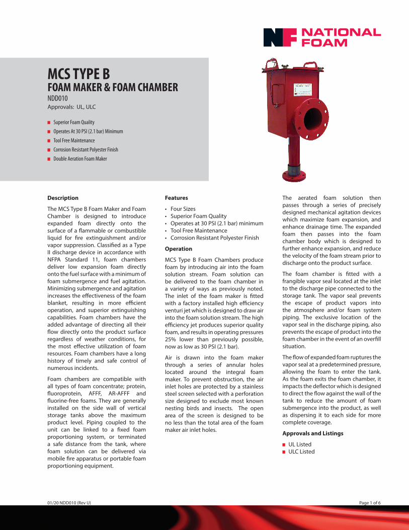
MCS TYPE B FOAM MAKER & FOAM CHAMBER NDD010 Approvals: UL, ULC Superior Foam Quality Operates At 30 PSI (2.1 bar) Minimum Tool Free Maintenance Corrosion Resistant Polyester Finish Double Aeration Foam Maker Description The MCS Type B Foam Maker and Foam Chamber is designed to introduce expanded foam directly onto the surface of a flammable or combustible liquid for fire extinguishment and/or vapor suppression. Classified as a Type II discharge device in accordance with NFPA Standard 11, foam chambers deliver low expansion foam directly onto the fuel surface with a minimum of foam submergence and fuel agitation. Minimizing submergence and agitation increases the effectiveness of the foam blanket, resulting in more efficient operation, and superior extinguishing capabilities. Foam chambers have the added advantage of directing all their flow directly onto the product surface regardless of weather conditions, for the most effective utilization of foam resources. Foam chambers have a long history of timely and safe control of numerous incidents. Foam chambers are compatible with all types of foam concentrate; protein, fluoroprotein, AFFF, AR-AFFF and fluorine-free foams. They are generally installed on the side wall of vertical storage tanks above the maximum product level. Piping coupled to the unit can be linked to a fixed foam proportioning system, or terminated a safe distance from the tank, where foam solution can be delivered via mobile fire apparatus or portable foam proportioning equipment. Features • Four Sizes • Superior Foam Quality • Operates at 30 PSI (2.1 bar) minimum • Tool Free Maintenance • Corrosion Resistant Polyester Finish Operation MCS Type B Foam Chambers produce foam by introducing air into the foam solution stream. Foam solution can be delivered to the foam chamber in a variety of ways as previously noted. The inlet of the foam maker is fitted with a factory installed high efficiency venturi jet which is designed to draw air into the foam solution stream. The high efficiency jet produces superior quality foam, and results in operating pressures 25% lower than previously possible, now as low as 30 PSI (2.1 bar). Air is drawn into the foam maker through a series of annular holes located around the integral foam maker. To prevent obstruction, the air inlet holes are protected by a stainless steel screen selected with a perforation size designed to exclude most known nesting birds and insects. The open area of the screen is designed to be no less than the total area of the foam maker air inlet holes. The aerated foam solution then passes through a series of precisely designed mechanical agitation devices which maximize foam expansion, and enhance drainage time. The expanded foam then passes into the foam chamber body which is designed to further enhance expansion, and reduce the velocity of the foam stream prior to discharge onto the product surface. The foam chamber is fitted with a frangible vapor seal located at the inlet to the discharge pipe connected to the storage tank. The vapor seal prevents the escape of product vapors into the atmosphere and/or foam system piping. The exclusive location of the vapor seal in the discharge piping, also prevents the escape of product into the foam chamber in the event of an overfill situation. The flow of expanded foam ruptures the vapor seal at a predetermined pressure, allowing the foam to enter the tank. As the foam exits the foam chamber, it impacts the deflector which is designed to direct the flow against the wall of the tank to reduce the amount of foam submergence into the product, as well as dispersing it to each side for more complete coverage. Approvals and Listings UL Listed ULC Listed 01/20 NDD010 (Rev U) Page 1 of 6
Transcript of MCS TYPE B - nationalfoam.com
MCS TYPE B FOAM MAKER & FOAM CHAMBERNDD010Approvals: UL, ULC
Superior Foam Quality
Operates At 30 PSI (2.1 bar) Minimum
Tool Free Maintenance
Corrosion Resistant Polyester Finish
Double Aeration Foam Maker
Description
The MCS Type B Foam Maker and Foam Chamber is designed to introduce expanded foam directly onto the surface of a fl ammable or combustible liquid for fi re extinguishment and/or vapor suppression. Classifi ed as a Type II discharge device in accordance with NFPA Standard 11, foam chambers deliver low expansion foam directly onto the fuel surface with a minimum of foam submergence and fuel agitation. Minimizing submergence and agitation increases the eff ectiveness of the foam blanket, resulting in more effi cient operation, and superior extinguishing capabilities. Foam chambers have the added advantage of directing all their fl ow directly onto the product surface regardless of weather conditions, for the most eff ective utilization of foam resources. Foam chambers have a long history of timely and safe control of numerous incidents.
Foam chambers are compatible with all types of foam concentrate; protein, fl uoroprotein, AFFF, AR-AFFF and fl uorine-free foams. They are generally installed on the side wall of vertical storage tanks above the maximum product level. Piping coupled to the unit can be linked to a fi xed foam proportioning system, or terminated a safe distance from the tank, where foam solution can be delivered via mobile fi re apparatus or portable foam proportioning equipment.
Features
• Four Sizes• Superior Foam Quality• Operates at 30 PSI (2.1 bar) minimum• Tool Free Maintenance• Corrosion Resistant Polyester Finish
Operation
MCS Type B Foam Chambers produce foam by introducing air into the foam solution stream. Foam solution can be delivered to the foam chamber in a variety of ways as previously noted. The inlet of the foam maker is fi tted with a factory installed high effi ciency venturi jet which is designed to draw air into the foam solution stream. The high effi ciency jet produces superior quality foam, and results in operating pressures 25% lower than previously possible, now as low as 30 PSI (2.1 bar).
Air is drawn into the foam maker through a series of annular holes located around the integral foam maker. To prevent obstruction, the air inlet holes are protected by a stainless steel screen selected with a perforation size designed to exclude most known nesting birds and insects. The open area of the screen is designed to be no less than the total area of the foam maker air inlet holes.
The aerated foam solution then passes through a series of precisely designed mechanical agitation devices which maximize foam expansion, and enhance drainage time. The expanded foam then passes into the foam chamber body which is designed to further enhance expansion, and reduce the velocity of the foam stream prior to discharge onto the product surface.
The foam chamber is fi tted with a frangible vapor seal located at the inlet to the discharge pipe connected to the storage tank. The vapor seal prevents the escape of product vapors into the atmosphere and/or foam system piping. The exclusive location of the vapor seal in the discharge piping, also prevents the escape of product into the foam chamber in the event of an overfi ll situation.
The fl ow of expanded foam ruptures the vapor seal at a predetermined pressure, allowing the foam to enter the tank. As the foam exits the foam chamber, it impacts the defl ector which is designed to direct the fl ow against the wall of the tank to reduce the amount of foam submergence into the product, as well as dispersing it to each side for more complete coverage.
Approvals and Listings
UL Listed ULC Listed
01/20 NDD010 (Rev U) Page 1 of 6

Specifi cations
The entire assembly shall consist of the foam chamber body with integral foam maker, factory installed integral venturi style jet, defl ector, defl ector mounting hardware, and gaskets. A lifting lug designed to support the weight of the assembly shall be provided. The foam defl ector shall be available in split or shallow confi gurations, and shall be suitable for bolting. The foam chamber body shall contain a frangible vapor seal positioned to prevent condensation and product vapors from entering the foam chamber body. The vapor seal shall be designed to rupture with a minimum inlet pressure of 30 PSI (2.1 bar) at the inlet to the foam chamber and shall withstand a maximum back pressure of 1.0 PSI (0.07 bar), or equal to 27 in. (686 mm) of water, as specifi ed by API for welded storage tanks. The vapor seal is fabricated of graphite with a Tefl on seal and is compatible with a wide range of corrosive chemicals. The vapor seal shall be a fully self-contained disc and shall not require adhesives, sealants, or loose gaskets to accomplish sealing. The vapor seal shall be held in place by a brass holder.Access to the frangible vapor seal shall be accomplished through a removable top cover, without the need to remove retaining nuts. All nuts shall be designed to be captive to prevent loss.All cover and vapor seal retaining hardware shall consist of stainless steel studs with brass nuts to resist galling, seizing, and corrosion. All carbon steel parts shall be abrasive blasted and coated with a fused polyester powder fi nish.The foam maker and foam chamber shall be UL Listed for operation as low as 30 PSI (2.1 bar).It shall be possible to test the foam maker and foam chamber assembly by removing the lid. Testing shall be accomplished with the vapor seal installed, and without damaging the seal. During testing the vapor seal shall
prevent test solution from entering the storage tank. No external sealing devices shall be necessary to accomplish testing. A drain shall be provided in the bottom of the foam chamber to allow for draining of the test solution. The drain shall be operable without tools.
Interchangeability
MCS Type B Foam Makers and Foam Chambers are dimensionally equivalent to prior Model MCS and MCS Type A Foam Makers and Foam Chambers. All customer connection points are identical, eliminating the need for piping modifi cations when replacing earlier versions. Orifi ce plates and vapor seals from previous models are not compatible with MCS Type B.
Selection
MCS Type B Foam Makers and Foam Chambers are available in four sizes to suit most requirements. Refer to the National Foam Engineering Manual, and the applicable design standards and local codes to determine the required fl ow rate for the application. The foam maker can be sized to provide any fl ow and pressure that falls within the operational limits of the foam maker. To select the correct size of foam maker, see the fl ow range charts on page 4, which show the operational limits of each foam maker. If the fl ow rate falls within the range of more than one unit, either size may be utilized. To determine the correct orifi ce, you must determine the design fl ow required and the available pressure at the foam maker inlet. Generally, the higher the operating pressure, the better the quality of the foam produced. The better the foam quality, the more effi cient the operation, therefore, it is benefi cial to utilize the highest operating pressure economically feasible. After the fl ow and pressure have been determined, they can be plugged into the formula shown on page 4 to determine the actual orifi ce size required. Once the orifi ce size is determined, confi rm that
it falls within the orifi ce range shown for the selected size of foam maker. The required fl ow rate and inlet pressure must be specifi ed when ordering.Defl ectors are available in split, shallow or split shallow confi gurations. The split defl ector is designed to accommodate most installations, and can be installed from outside the tank. Shallow defl ectors are intended for use when the tank is fi tted with a fl oating roof which may pass over the defl ector, minimizing possible damage to the roof seals. Shallow defl ectors must be installed from inside the tank. The split shallow defl ector is designed to accommodate most internal fl oating roof applications and can be installed from the outside of the tank. All Defl ector mounting hardware is included.
Materials of Construction
Body ..........................................Carbon Steel ASTM A569 & A53Jet/Receiver ......................... Silicon Bronze ASTM B30 C87300Defl ector ..........Carbon Steel ASTM A569Drain Plug ..........................Brass ASTM B62Flange Gaskets .....High Temp. Synthetic Fiber w/ Nitrile or EPDM Binders
• Inlet Gasket ................1/16”(1.6 mm)• Discharge Gasket ....... 1/8”(3.2 mm)
Vapor Seal Disk ...Tefl on Coated GraphiteVapor Seal Holder .............. Silicon Bronze ASTM B62 C83600Vapor Seal Gasket .............................. Tefl on Encapsulated VitonWing Nuts ..........................Brass ASTM B62Internal and External ........Stainless Steel
Studs and Nuts ASTM 18-8Air Strainer .....Stainless Steel Perf 22 GALid Gasket .........Silicon Foam - Close Cell w/PSA Adhesive One SideFinish:
• Foam Chamber Body and Defl ector:Abrasive blast to SSPC-SP6 Chemical wash, rinse and seal. Heat Fusion Coated Polyester Powder Coat, 3 mils DFT.
• All Other Components: Natural Finish
MCS TYPE B FOAM MAKER & FOAM CHAMBERNDD010
Page 2 of 6 01/20 NDD010 (Rev U)

MCS TYPE B FOAM MAKER & FOAM CHAMBERNDD010
01/20 NDD010 (Rev U) Page 3 of 6
ORDERING INFORMATION - MCS TYPE B FOAM CHAMBER WITH DEFLECTOR
SIZE WITH SPLIT DEFLECTOR WITH SHALLOW DEFLECTOR SPLIT SHALLOW DEFLECTOR ONLY
MCS-9 1253-1651-2 1253-1651-3 1253-1763-1
MCS-17 1253-2651-2 1253-2651-3 1253-1765-1
MCS-33 1253-3651-2 1253-3651-3 1253-1767-1
MCS-55 1253-4651-2 1253-4651-3 1253-1769-1
Split Defl ector
Shallow Defl ector Split Shallow Defl ector
REMOVABLE LID
FOAM CHAMBERLABEL
AIR STRAINER
COMPANIONFLANGES
FOAM SOLUTIONRISER
COMPANIONFLANGES
COMPANIONFLANGES
SWING JOINT
PLUG
SLOPE FOR DRAINAGE
FOAM CHAMBER INSTALLATION
DEFLECTOR
TANKSHELL
ORDERING INFORMATION - MCS TYPE B FOAM CHAMBER WITHOUT DEFLECTOR
SIZE RED CHAMBER YELLOW CHAMBER STAINLESS STEEL CHAMBER
MCS-91253-1651-1 (Hi-Flow)
1253-1651-5 (Lo-Flow)
1253-1661-1 (Hi-Flow)
1253-1661-4 (Lo-Flow)
1253-1652-1 (Hi-Flow)
1253-1652-4 (Lo-Flow)
MCS-17 1253-2651-1 1253-2661-1 1253-2652-1
MCS-33 1253-3651-1 1253-3661-1 1253-3652-1
MCS-55 1253-4651-1 1253-4661-1 1253-4652-1
NOTE:
All foam chambers are supplied with vapor seal holder and vapor seal.When ordering please supply the following information: tank identifi cation, tank size and type, product being stored, fl ow and inlet pressure at each foam chamber, defl ector type (if required), foam concentrate type, and percentage of concentration.

The following are the maximum and minimum jet sizes for each foam maker size and the C factor for each jet:
MCS-9 (C = 0.920) English Metric
Smallest Jet------ 0.504” (12.8016 mm) Dia ............................38.1 GPM .......@ ....... 30 PSI 144.4 LPM .......@....... 2.068 BAR 49.1 GPM .......@ ....... 50 PSI 185.9 LPM .......@....... 3.447 BAR 62.2 GPM .......@ ....... 80 PSI 235.5 LPM .......@....... 5.516 BAR 69.6 GPM .......@ ....... 100 PSI 263.6 LPM .......@....... 6.895 BAR
Largest Jet ------- 0.760” (19.3040 mm) Dia ............................86.7 GPM .......@ ....... 30 PSI 328.3 LPM .......@....... 2.068 BAR 111.8 GPM .......@ ....... 50 PSI 423.2 LPM .......@....... 3.447 BAR 141.6 GPM .......@ ....... 80 PSI 536.0 LPM .......@....... 5.516 BAR 158.4 GPM .......@ ....... 100 PSI 599.4 LPM .......@....... 6.895 BAR
MCS-17 (C = 0.870)
Smallest Jet------ 0.721” (18.3134 mm) Dia ............................73.8 GPM .......@ ....... 30 PSI 279.4 LPM .......@....... 2.068 BAR 95.2 GPM .......@ ....... 50 PSI 360.4 LPM .......@....... 3.447 BAR 120.5 GPM .......@ ....... 80 PSI 456.1 LPM .......@....... 5.516 BAR 134.8 GPM .......@ ....... 100 PSI 510.2 LPM .......@....... 6.895 BAR
Largest Jet ------- 1.051” (26.6954 mm) Dia. .........................156.9 GPM .......@ ....... 30 PSI 593.8 LPM .......@....... 2.068 BAR 202.4 GPM .......@ ....... 50 PSI 766.1 LPM .......@....... 3.447 BAR 256.2 GPM .......@ ....... 80 PSI 969.8 LPM .......@....... 5.516 BAR 286.4 GPM .......@ ....... 100 PSI 1084.1 LPM .......@....... 6.895 BAR
MCS-33 (C = 0.973)
Smallest Jet------ 0.980” (24.8920 mm) Dia ..........................152.5 GPM .......@ ....... 30 PSI 577.4 LPM .......@....... 2.068 BAR 196.8 GPM .......@ ....... 50 PSI 745.0 LPM .......@....... 3.447 BAR 249.0 GPM .......@ ....... 80 PSI 942.6 LPM .......@....... 5.516 BAR 278.5 GPM .......@ ....... 100 PSI 1054.1 LPM .......@....... 6.895 BAR
Largest Jet ------- 1.530” (39.8620 mm) Dia ..........................371.8 GPM .......@ ....... 30 PSI 1407.3 LPM .......@....... 2.068 BAR 479.6 GPM .......@ ....... 50 PSI 1815.5 LPM .......@....... 3.447 BAR 607.0 GPM .......@ ....... 80 PSI 2297.7 LPM .......@....... 5.516 BAR 678.8 GPM .......@ ....... 100 PSI 2569.4 LPM .......@....... 6.895 BAR
MCS-55 (C = 0.880)
Smallest Jet------ 1.457” (37.0078 mm) Dia ..........................304.9 GPM .......@ ....... 30 PSI 1154.2 LPM .......@....... 2.068 BAR 393.6 GPM .......@ ....... 50 PSI 1489.9 LPM .......@....... 3.447 BAR 497.9 GPM .......@ ....... 80 PSI 1884.7 LPM .......@....... 5.516 BAR 556.7 GPM .......@ ....... 100 PSI 2107.4 LPM .......@....... 6.895 BAR
Largest Jet ------- 1.987” (50.4698 mm) Dia ..........................567.1 GPM .......@ ....... 30 PSI 2146.7 LPM .......@....... 2.068 BAR 731.6 GPM .......@ ....... 50 PSI 2769.4 LPM .......@....... 3.447 BAR 926.0 GPM .......@ ....... 80 PSI 3505.2 LPM .......@....... 5.516 BAR 1035.4 GPM .......@ ....... 100 PSI 3919.4 LPM .......@....... 6.895 BAR
MCS TYPE B FOAM MAKER & FOAM CHAMBERNDD010
Page 4 of 6 01/20 NDD010 (Rev U)
Legend: Q - Flow in GPM (LPM) D - Diameter of Jet in Inches (MM) C - Coeffi cient of Discharge for the Jet (See Orifi ce Jet Sizing Chart) P - Pressure in PSI (BAR)
D =Q
English
P29.8 x C x D =Q
Metric
P0.6659 x C x
Orifi ce Jet Sizing - MCS Type B Foam Makers
All foam makers shall be sized using the following formula:

MCS TYPE B FOAM MAKER & FOAM CHAMBERNDD010
01/20 NDD010 (Rev U) Page 5 of 6
MOUNTING JACKSCREW(IN COMPRESSION)
FOR MCS-17, MCS-33 & MCS-55 VAPOR SEALDISK
JACKSCREWS
HOLDER
HOLDER
MOUNTING STUDWITH
BRASS WINGNUT(IN TENSION)
MCS-17, MCS-33 & MCS-55VAPOR SEAL & HOLDER MOUNTING
VAPOR SEALDISK
HOLDER
HOLDER
MOUNTING STUDWITH
BRASS WINGNUT(IN TENSION)
MCS-9VAPOR SEAL & HOLDER MOUNTING
VAPOR SEAL ORDERING INFORMATION
SIZE
COMPATIBLE
JET ORIFICE SIZE VAPOR SEAL DISK
VAPOR SEAL KIT
WITH HOLDER
MCS-9 Low Flow .504 - .620 1253-1840-7 1253-1840-5
MCS-9 Hi Flow .621 - .760 1253-1840-8 1253-1840-6
MCS-17 ALL SIZES 1253-2840-7 1253-2840-6
MCS-33 ALL SIZES 1253-3840-7 1253-3840-6
MCS-55 ALL SIZES 1253-4840-7 1253-4840-6
SCREEN GUARD
ORDERING INFORMATION
FOAM CHAMBER
SCREEN GUARD
PART NUMBER
MCS-9 1253-1920-3
MCS-17 1253-2920-3
MCS-33 1253-3920-3
MCS-55 1253-4920-3
Vapor Seal Ordering Information
Vapor Seal Disks are available with or without the holder. Foam chambers shipped after October 2003 are provided with the brass vapor seal holder and require the purchase of only the vapor seal.
Foam Chamber Accessory - Screen
Guard
The Foam Chamber Screen Guard is designed to prevent birds and animals from entering the foam chamber through the chamber discharge fl ange opening. NOTE: The Screen Guard is
used on fl oating roof applications
where the Vapor Seal is not used. The
Screen Guard is ordered separately
from the foam chamber.
Foam chambers shipped prior to October 2003 have a vapor seal cartridge (graphite vapor seal, Viton seal & stainless steel holder) which is no longer available. Replacement vapor seals for these chambers require the purchase of the vapor seal kit
with holder. Future replacements only require the replacement of the vapor seal after installation of the brass holder. See pages 5 and 6 for Vapor Seal and Holder Mounting.
THUMB SCREW
FOAM CHAMBERDISCHARGE FLANGE
SCREENGUARD
ASSEMBLY
National Foam operates a continuous program of product development. The right is therefore reserved to modify any specifi cation without prior notice and National Foam should be contacted to ensure that the current issues of all technical data sheets are used.© National Foam
National Foam350 East Union Street, West Chester, PA 19382, USA24hr RED ALERT® : 610-363-1400 • Fax: 610-431-7084www.nationalfoam.com
Page 6 of 6 01/20 NDD010 (Rev U)
MCS TYPE B FOAM MAKER & FOAM CHAMBERNDD010
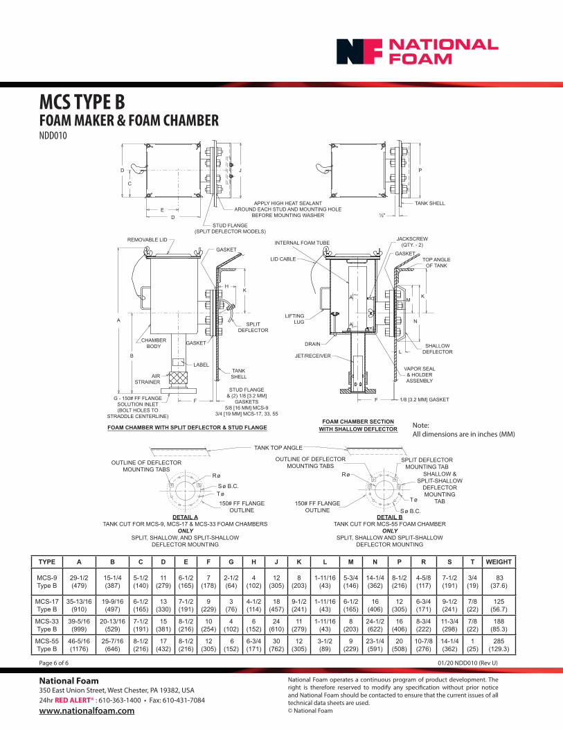
Note:All dimensions are in inches (MM)
TYPE A B C D E F G H J K L M N P R S T WEIGHT
MCS-9Type B
29-1/2 (479)
15-1/4 (387)
5-1/2 (140)
11 (279)
6-1/2 (165)
7 (178)
2-1/2 (64)
4 (102)
12 (305)
8 (203)
1-11/16 (43)
5-3/4 (146)
14-1/4 (362)
8-1/2 (216)
4-5/8 (117)
7-1/2 (191)
3/4 (19)
83(37.6)
MCS-17Type B
35-13/16 (910)
19-9/16 (497)
6-1/2 (165)
13 (330)
7-1/2 (191)
9 (229)
3 (76)
4-1/2 (114)
18 (457)
9-1/2 (241)
1-11/16 (43)
6-1/2 (165)
16 (406)
12 (305)
6-3/4 (171)
9-1/2 (241)
7/8 (22)
125(56.7)
MCS-33Type B
39-5/16 (999)
20-13/16 (529)
7-1/2 (191)
15 (381)
8-1/2 (216)
10 (254)
4 (102)
6 (152)
24 (610)
11 (279)
1-11/16 (43)
8 (203)
24-1/2 (622)
16 (406)
8-3/4 (222)
11-3/4 (298)
7/8 (22)
188(85.3)
MCS-55Type B
46-5/16 (1176)
25-7/16 (646)
8-1/2 (216)
17 (432)
8-1/2 (216)
12 (305)
6 (152)
6-3/4 (171)
30 (762)
12 (305)
3-1/2 (89)
9 (229)
23-1/4 (591)
20 (508)
10-7/8 (276)
14-1/4 (362)
1 (25)
285 (129.3)
F
B
A
CHAMBERBODY
AIRSTRAINER
G - 150# FF FLANGESOLUTION INLET(BOLT HOLES TO
STRADDLE CENTERLINE)
REMOVABLE LID
FOAM CHAMBER WITH SPLIT DEFLECTOR & STUD FLANGE
STUD FLANGE(SPLIT DEFLECTOR MODELS)
APPLY HIGH HEAT SEALANTAROUND EACH STUD AND MOUNTING HOLE
BEFORE MOUNTING WASHERD
J
E
D
C
F
A
A
JACKSCREW(QTY. - 2)
JET/RECEIVER
DRAIN
LIFTINGLUG
LID CABLE
INTERNAL FOAM TUBE
FOAM CHAMBER SECTIONWITH SHALLOW DEFLECTOR
P
TANK SHELL
KH
TANKSHELL
SPLITDEFLECTOR
STUD FLANGE& (2) 1/8 [3.2 MM]
GASKETS5/8 [16 MM] MCS-9
3/4 [19 MM] MCS-17, 33, 55
GASKET
KM
N
L
TOP ANGLEOF TANK
SHALLOWDEFLECTOR
VAPOR SEAL& HOLDERASSEMBLY
GASKET
GASKET
½"
LABEL
1/8 [3.2 MM] GASKET
OUTLINE OF DEFLECTORMOUNTING TABS
S ø B.C.T ø
R ø
S ø B.C.
T ø
R ø
TANK TOP ANGLE
OUTLINE OF DEFLECTORMOUNTING TABS
DETAIL BTANK CUT FOR MCS-55 FOAM CHAMBER
ONLYSPLIT, SHALLOW AND SPLIT-SHALLOW
DEFLECTOR MOUNTING
DETAIL ATANK CUT FOR MCS-9, MCS-17 & MCS-33 FOAM CHAMBERS
ONLYSPLIT, SHALLOW, AND SPLIT-SHALLOW
DEFLECTOR MOUNTING
150# FF FLANGEOUTLINE
150# FF FLANGEOUTLINE
SPLIT DEFLECTORMOUNTING TAB
SHALLOW &SPLIT-SHALLOW
DEFLECTORMOUNTING
TAB


![PDF] Renewables• UK: IEC 61400-2, MCS (small WT) • German type approval (DiBT) • Korean type approval (KEA Scheme) Type Certification Process. After completing the type certification](https://static.fdocuments.us/doc/165x107/612d74051ecc5158694232d6/-renewablesa-uk-iec-61400-2-mcs-small-wt-a-german-type-approval-dibt.jpg)