
McL-10H - Amazon Simple Storage Service · DANGER! Do not enter the exit pit if the machine has...
26
Transcript of McL-10H - Amazon Simple Storage Service · DANGER! Do not enter the exit pit if the machine has...

McL-10H
Pit-Launch Directional Drill
Safety and
Operation Manual
5 & 7 ft (152 & 213 cm) Models
Part Number: E250205
Revision: 01

Foreword
This manual contains important safety information and operational instructions for your machine. Read and fully understand this manual before operating the machine. Failure to do so may result in serious injury, death, property damage, or equipment damage. IMPORTANT: Always consult with your dealer or McLaughlin Group, Inc. before operating this machine if you do not fully understand any instruction(s); safety information; safety message(s); safety decal(s); the function of any machine component or control; or need addition information. Keep a copy of this manual in the black storage box (located on the machine) at all times for reference. If the machine is sold, ensure the new owner receives the manual with the machine. Instructions, illustrations, photos, and specifications are subject to change without notice or obligation. McLaughlin Group, Inc. reserves the right to make product changes at any time without notice or obligation. Contact your dealer for the latest information on McLaughlin Group, Inc. equipment. Replacement copies of this manual are available through your dealer or by contacting McLaughlin Group, Inc. directly at: McLaughlin Group, Inc. 2006 Perimeter Road Greenville, SC 29605 U.S.A.
Toll free: 800-435-9340 World Wide: 864-277-5870 Fax: 864-235-9661
Email: [email protected]
Website: www.mightymole.com
© 2013 by McLaughlin Group, Inc.
All rights reserved. No part of this manual may be reproduced in any form,
or by any means without prior written permission of McLaughlin Group, Inc.
Printed in the U.S.A

Table of Contents Section
Safety Messages ....................................................................................... 1
Intended Use ............................................................................................. 2
Decals ....................................................................................................... 3
Controls and Gauges ................................................................................ 4
Preparation ................................................................................................ 5
Operation ................................................................................................... 6
Warranty and Return Policy ...................................................................... 7
Specifications ............................................................................................ 8

Section 1: Safety Messages
IMPORTANT: Read and understand all Safety Messages in this section and all Decals on the machine before operating this equipment. Safety messages in this manual and safety decals on the machine use the following signal words: DANGER, WARNING, and CAUTION.
DANGER: Indicates an imminent hazardous situation which, if not avoided, will result in death or serious personal injury. WARNING: Indicates a potentially hazardous situation which, if not avoided, may result in death or serious personal injury. CAUTION: Indicates a potentially hazardous situation or unsafe practice which, if not avoided, may result in serious personal injury, property or product damage.
PERSONEL
WARNING! Read and understand all sections of this manual and all
decals on the machine before operating the equipment.
WARNING! Allow only authorized and properly trained personnel to
operate this machine.
WARNING! Operators must be mentally and physically capable of
responsibly operating the machine.
WARNING! Failure to follow the information contained in this manual
or decals on the machine which can result in serious injury or death.
WARNING! Wear Personal Protective Equipment (PPE). Refer to
Section 5: Preparation.
WARNING! Do not wear loose clothing; keep long hair confined; do
not wear jewelry (bracelets, necklaces, rings, or watches) which can become caught in rotating or moving machine components. Entanglement with a rotating drill rod, cutting, tool, or reamer can result in serious injury or death.

PREPARATION
WARNING! Contact the One-Call system before each pit excavation
and directional drilling project.
WARNING! Do not enter a pit with unstable sides which could cave in.
Specifications for shoring up or sloping pit walls are available from O.S.H.A. Contact O.S.H.A. for these and other requirements before entering the pit.
WARNING! Lift machine or rod box only with suitable lifting
equipment. Ensure the load stays level while lifting. WARNING! Do not raise or lift the machine or rod box over personnel.
The load can fall or shift which can result in serious injury or death.
WARNING! Do not position a long side of the rod box parallel with the
entry pit or the pit wall may cave-in, spilling rod box contents onto the operator which can result in serious injury or death. Always position the rod box perpendicular to the entry pit so rods can be pulled out of the short end of the rod box.
WARNING! Do not operate the machine until the Strike Alert system
has been tested and confirmed to be in good operational condition. See Section 5: Preparation.
CAUTION! Do not allow spectators near the work site.
OPERATION
DANGER! Always stand on the operator platform while operating the
machine. Electrical line contact can result in electrocution. In the event of an electrical strike, stepping off of the machine, contact with pit walls, or contact with the machine while standing on the ground, can result in electrocution. Do not allow people to approach the machine. The utility company must be contacted immediately to turn the electrical source off.
DANGER! A ruptured gas line can cause a fire or an explosion which
can result in serious injury or death. If a gas line is struck, shut down the power source and leave the area immediately. Do not allow people to approach the work site. Call 911 and the utility company immediately. Do not return to the work site until the gas company states it is safe to do so.

DANGER! Do not enter the exit pit if the machine has power to rotate,
thrust, or retract the drill rod string. Any movement in the drill rod string can result in serious injury or death.
DANGER! The machine’s power source must be shut down before
personnel enter the exit pit. Always use a lock-out / tag-out procedure while working in the exit pit. The power source ignition key must be in the possession of the worker(s) entering the exit pit. Following this procedure prevents the drill rod string; any attachment on the drill rod string; or any tool attached to the drill rod string from rotating, thrusting, or retracting which can result in serious injury or death.
DANGER! Do not use tools to make or break joints in the entry pit.
Rotation will move the tool and can cause serious injury or death.
WARNING! Avoid all moving parts and pinch points. Moving parts and
pinch points can cause serious injury or death. Ensure all shields are in good condition and properly installed.
WARNING! Any fluid under high pressure can penetrate the body and
result in serious injury or death. Leaks can be nearly invisible. Seek immediate, professional assistance if fluid is injected into any body part.
WARNING! Light emitted from broken fiber optic lines can damage
eye site. If a fiber optic line is broken, do not look into the cable. Contact the communication line company for assistance.
MAINTENANCE
WARNING! Inspect machine daily. Machine must be in proper
operating condition, with all safety shields installed, before operating.
WARNING! Allow only authorized and properly trained personnel to
perform maintenance on this machine.
WARNING! Shut down the machine’s power source and remove the
key, before performing any maintenance or repairs.
WARNING! Keep all machine decals in good, readable condition.
Replace worn, damaged, or missing decals immediately.
CAUTION! Do not modify the machine. Modifications can cause
equipment damage, property damage, or result in serious injury. Modification(s) may void the warranty.

Section 2: Intended Use The McL-10H Pit-Launch Directional Drill is engineered to bore, short
distances, horizontally into the earth. Utility services or communication
cables are pulled back through the bore created in the drilling process.
Only use this machine in conjunction with the instructions and safety
messages in this manual; machine decals; and any other information
supplied by McLaughlin Group, Inc.
Inspect the unit daily and make necessary repairs before operating the
machine. Never operate the machine if a repair is needed or the machine
is not in proper operating condition.
This machine is hydraulically powered by a separate source. Refer to the
Operation Manual of the power source for safety information and
operational instructions.
Water or drilling fluids for this machine are supplied by a separate
source. Refer to the Operation Manual of the fluid system for safety
information and operational instructions.

Section 3: Decals
IMPORTANT: Read and understand all Safety Messages (see Section 1) and Decals on the machine before operating this equipment. Machine decals contain important information to help operate this machine safely. Ensure all decals remain in place and are in good condition. Keep decals clean. Replace damaged or missing decals. NOTE: When a machine component with a decal is replaced, install a replacement decal on the new component. Purchase replacement decals from your McLaughlin dealer or McLaughlin Group, Inc. direct.
J000035
J800030
J000160
J000210
J800270
J000140
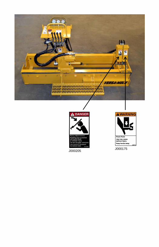
J000205
J000175

E.U. Decals
J200004
J200003
J2000421

J200456

Section 4: Controls and Gauges
IMPORTANT: Read and understand all Safety Messages (see Section 1) and Decals on the machine before operating this equipment.
Pressure Gauges
Rotation
Thrust
Drilling Fluid
Control Levers
Rotation
Carriage
Rear Clamp
Front Clamp
Hydraulic
Connectors
Lift Point
Serial Number
Manual Box
Strike Alert
Connector
Drilling Fluid
Connector
Strike Alert
Power Cable
Strike Alert Siren
Strike Alert
Ground Stake
Strike Alert Cable
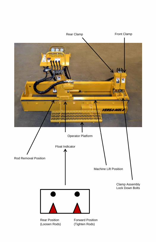
Operator Platform
Float Indicator
Machine Lift Position
Rod Removal Position
Rear Clamp
Front Clamp
Rear Position Forward Position
(Loosen Rods) (Tighten Rods)
Clamp Assembly Lock Down Bolts
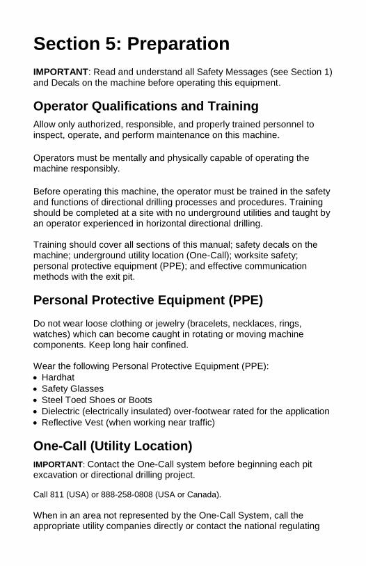
Section 5: Preparation
IMPORTANT: Read and understand all Safety Messages (see Section 1) and Decals on the machine before operating this equipment.
Operator Qualifications and Training
Allow only authorized, responsible, and properly trained personnel to inspect, operate, and perform maintenance on this machine.
Operators must be mentally and physically capable of operating the machine responsibly.
Before operating this machine, the operator must be trained in the safety and functions of directional drilling processes and procedures. Training should be completed at a site with no underground utilities and taught by an operator experienced in horizontal directional drilling. Training should cover all sections of this manual; safety decals on the machine; underground utility location (One-Call); worksite safety; personal protective equipment (PPE); and effective communication methods with the exit pit.
Personal Protective Equipment (PPE) Do not wear loose clothing or jewelry (bracelets, necklaces, rings, watches) which can become caught in rotating or moving machine components. Keep long hair confined. Wear the following Personal Protective Equipment (PPE):
Hardhat
Safety Glasses
Steel Toed Shoes or Boots
Dielectric (electrically insulated) over-footwear rated for the application
Reflective Vest (when working near traffic)
One-Call (Utility Location)
IMPORTANT: Contact the One-Call system before beginning each pit excavation or directional drilling project. Call 811 (USA) or 888-258-0808 (USA or Canada).
When in an area not represented by the One-Call System, call the appropriate utility companies directly or contact the national regulating
authority to locate and mark underground utilities. If you do not call, you may have an accident; suffer injuries or death; cause utility service interruption(s); cause damage to the environment; encounter significant job delays; or be liable for costly utility repair bills.
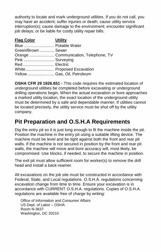
Flag Color Utility
Blue ........................... Potable Water Green/Brown ............. Sewer Orange ...................... Communication, Telephone, TV Pink ........................... Surveying Red ............................ Electric White ......................... Proposed Excavation Yellow ........................ Gas, Oil, Petroleum OSHA CFR 29 1926.651 - This code requires the estimated location of underground utilities be completed before excavating or underground drilling operations begin. When the actual excavation or bore approaches a marked utility location, the exact location of the underground utility must be determined by a safe and dependable manner. If utilities cannot be located precisely, the utility service must be shut off by the utility company.
Pit Preparation and O.S.H.A Requirements
Dig the entry pit so it is just long enough to fit the machine inside the pit. Position the machine in the entry pit using a suitable lifting device. The machine must be level and be tight against both the front and rear pit walls. If the machine is not secured in position by the front and rear pit walls, the machine will move and bore accuracy will, most likely, be compromised. Use blocks, if needed, to secure the machine in position.
The exit pit must allow sufficient room for worker(s) to remove the drill head and install a back-reamer. All excavations on the job site must be constructed in accordance with Federal, State, and Local regulations. O.S.H.A. regulations concerning excavation change from time to time. Ensure your excavation is in accordance with CURRENT O.S.H.A. regulations. Copies of O.S.H.A. regulations are available free of charge by writing:
Office of Information and Consumer Affairs US Dept. of Labor – OSHA Room N-3637 Washington, DC 20210

Rod Box Location
Position the rod box near the entry pit with a suitable lifting device.
IMPORTANT: Do not position a long side of the rod box parallel with the entry pit or the pit wall may cave-in, spilling rod box contents onto the operator causing serious injury or death. Always position the rod box perpendicular to the entry pit so rods can be pulled out of the short end of the rod box.
NOTE: Only one end of the rod box is removable, allowing drill rods to be easily pulled out of the rod box.
IMPORTANT: After rods have been placed back into the rod box, install rod box end and securely tighten bolts before moving or lifting the rod box.
Strike Alert
WARNING: It is important to read and understand these instructions before using the ZAP-ALERTTM. The ZAP-ALERTTM is an electrical power line strike indicator to be used in conjunction with earth boring equipment. The ZAP-ALERTTM signals contact and damage to buried power lines from 100 volts AC to 100,000 volts AC. Any voltage over 42 volts peak between the ZAPALERTTM unit and the grounding stake will trigger the alarm. WARNING: The ZAP-ALERTTM will not be set off by coming near a power source. It only sounds an alert after electrical contact has been made. Safety equipment and safety apparel must be used at all times. Mounting: The ZAP-ALERTTM is mounted under the console. The power outlet for ZAP-ALERTTM is adjacent to it. The female receptacle is used to bring power from the power cable to the ZAP-ALERTTM siren.
Operation
Power Source: The ZAP-ALERTTM uses a standard 12-volt DC power source. Connect the black wire of the power cable to the positive (+) battery terminal and the white wire to the negative (-) battery terminal. Do not use any fuses in the lines powering the ZAP-ALERTTM. The ZAP-ALERTTM must always have power whenever in use. Do not connect the power source to a switch that may inadvertently be turned off while working. Plug the power cord into the female receptacle on the console.
Sensing Stake: The sensing stake should be connected to the insulated bolt on the front of the ZAP-ALERTTM box. Push the sensing stake into the ground at least 6’ away from the equipment, perpendicular to the bore path. It is important for the earth stake to be inserted into soil which electrical current can pass through. If the earth stake is in extremely dry soil or asphalt, the ZAP-ALERTTM may not function. If it must be inserted in extremely dry soil, moisten the soil around the sensing stake to improve soil conductivity. Be sure to fully insert the sensing stake into the ground. Insulated Blanket:
IMPORTANT: The insulated blanket must be positioned to protect the operator from inadvertent contact with the pit wall. Place the blanket in the desired position and attach the blanket to the wall with stakes provided or secure by an appropriate means. Testing: Connect the power cord to the power source and to the female receptacle on the console. Lay the sensing stake on the ground. (Do not insert the stake into the ground at this time.) Connect one lead of the test set to the sensing stake. Connect the other lead to an exposed metal part on the machine. Press the test button on the hand held tester. Check that the ZAP-ALERTTM siren is sounding. When you have confirmed the operation of the ZAPALERTTM, press the reset button to stop the siren. WARNING: Do not operate the machine unless the test system confirms that the ZAP-ALERTTM system is operational. Resetting After A Strike: Once you have made a strike, the siren will continue to sound as long as current is passing into the machine and soil. If you attempt to reset the ZAP-ALERTTM, the siren will not stop until the current has stopped. WARNING: Do not stop the siren by resetting the ZAP-ALERTTM until you have confirmed that the electric power has been locked out. If the power has not been properly shut off, an automatically resetting circuit breaker could reenergize the power line, or contact between the boring tool and power line may recur if they are close to each other.
Section 6: Operation
IMPORTANT: Read and understand all Safety Messages (see Section 1) and Decals on the machine before operating this equipment. IMPORTANT: Do not use tools to make or break joints in the entry pit. Rotation will move the tool and can cause serious injury or death. IMPORTANT: Always stand on the work platform while operating the machine. Electrical line contact can result in electrocution. In the event of an electrical strike, stepping off of the machine, contact with pit walls, or contact with the machine while standing on the ground, can result in electrocution. Do not allow people to approach the machine. The utility company must be contacted immediately to turn the power source off. IMPORTANT: The insulated blanket must be positioned to protect the operator from inadvertent contact with the pit wall. Place the blanket in the desired position and attach the blanket to the wall with stakes provided or secure by an appropriate means. IMPORTANT: A ruptured gas line can cause an explosion. If a gas line is struck, shut down the power source and leave the area immediately. Do not allow people to approach the work site. Call 911, then contact the utility company immediately and do not return to the work site until the utility company says it is safe to do so.
Starting the Bore
Pre-Bore
NOTE: This procedure is for the McL-10H 5 ft (152 cm) version only.
When boring with this version of the machine you must begin with a pilot hole to make room for the drill head.
1. Move carriage forward into rear clamp.
2. Engage rear clamp.
3. Loosen, but do not remove, six clamp assembly lockdown bolts. This allows the clamp assembly to slide.
4. Retract clamp assembly back to center of machine.
5. Release rear clamp and install Paddle Rod.
6. Rotate and Thrust forward until the Paddle Rod is completely buried into the pit face.

7. Retract carriage and pull the clamp assembly back to center of machine.
8. Remove Paddle Rod. The pilot bore is completed.
Boring
Installing the Drill Head
1. Loosen, but do not remove, six clamp assembly lockdown bolts. This allows the clamp assembly to slide.
2. Move carriage forward into rear clamp..
3. Engage rear clamp.
4. Retract carriage back to center of machine.
5. Release the rear clamp and install drill head.
6. Rotate and Thrust forward until drill head is fully in the pit face and the carriage has gone as far forward as possible.
7. Engage front clamp and break the chuck loose from the drill head using counterclockwise rotation.
8. Tighten six clamp assembly lockdown bolts.
9. Retract carriage to rear most position.
Installing and Removing Rods
NOTE: The machine carriage has a float indicator to prevent damaging threads. The float indicator has a front and rear position. See Section 4: Controls and Gauges.
Installing Rods
1. Apply approved thread lubricant each time a rod is installed. Failure to do so will damage threads.
2. Match male/female rod ends with male end facing the clamp assembly and female end facing the carriage.
3. Place new rod into the existing rod and turn 1-2 times to engage threads.
4. Move carriage forward and position the rod so the chuck threads into the rod. The float-indicator should be at the forward position.
5. Engage front clamp.
6. Rotate chuck clockwise, but do not thrust. Allow carriage to “walk” forward as chuck and the rod screw together.

7. Rotate clockwise until full system pressure is reached ensuring joint is tightened.
8. Release front clamp.
9. Turn drilling fluid on.
10. Install additional rods as needed.
NOTE: Turn drilling fluid off before adding rods.
Removing Rods
1. Turn drilling fluid off.
2. If back reaming or retrieving a service is necessary, see Back-Reaming section.
3. Rotate rods in clockwise direction and retract carriage until front of carriage reaches Rod Removal Position. * NEVER ROTATE RODS COUNTER-CLOCKWISE *.
4. Engage front clamp to hold rod.
5. Retract carriage until Float Indicator is in the Rear Position. Engage rear clamp to engage and rotate counter-clockwise to loosen joint. If joint does not loosen, repeat.
6. Release rear clamp.
7. Rotate spindle 2-turns – counter-clockwise direction.
8. Engage rear clamp.
9. Rotate chuck counter-clockwise and unscrew chuck from rod.
10. Release the rear clamp and remove the rod.
11. Move the carriage forward until it reaches the rear clamp.
12. Slowly rotate the chuck clockwise and slowly move the carriage into the rear clamp.
NOTE: The chuck must be rotating slowly when you thrust forward to mate with the rod threads.
13. Re-engage front clamp.
14. Rotate the chuck clockwise and tighten the chuck into the rod.
15. Release front clamp.
16. Remove additional rods as needed.
Back-Reaming IMPORTANT: Do not enter the exit pit if the machine has power to rotate, thrust, or retract the drill rod string. Any movement in the drill rod string can cause serious injury or death. IMPORTANT: The power source for the machine must be shut down before personnel enter the exit pit. Always use a lockout / tag out procedure while working in the exit pit. The power source ignition key must be in the possession of the worker(s) entering the exit pit. Following this procedure prevents the drill rod string; any attachment on the drill rod string; or any tool attached to the drill rod string from rotating, thrusting, or pulling back – which can serious injury or death. IMPORTANT: The reamer is larger in diameter than the drill head. The reamer may come into contact with utilities that the drill head did not touch. Read and understand all Safety Messages (see Section 1) before back-reaming. 1. Remove directional drill head.
2. Install reamer.
3. Retract rods until the reamer engages the pit face.
IMPORTANT: Do not rotate the reamer.
4. Turn drilling fluid on.
5. Use clockwise rotation and retract the drill string. Never rotate counter-clockwise as in section - Removing Rods.
6. Remove drill rods until the reamer reaches the entry pit.
7. Turn drilling fluid off.
8. Pull reamer into the entry pit until it reaches the clamp assembly.
9. Loosen, but do not remove, six clamp assembly lockdown bolts.
Retract and pull it along with the clamp assembly back to center of machine.
IMPORTANT: Do not rotate the reamer.
10. Remove the reamer.

Section 7: Warranty & Returns
The Manufacturer warrants its products to be free from defects in material and
workmanship for a period of twelve months from the date of shipment from the
factory. The Manufacturer shall not be responsible for any damage resulting to or
caused by its products by reason of installation, improper storage, unauthorized
service, alteration of the products, neglect or abuse, or use of the product in a
manner inconsistent with its design. The warranty does not extend to any
component parts not manufactured by Manufacturer; however, Manufacturer's
warranty herein shall not limit any warranties made by manufacturers of
component parts which extend to Buyer.
Claims for defects in material and workmanship shall be made in writing to
Manufacturer within ten days of discovery of defect. Manufacturer may either
send a service representative or have the product returned to its factory at Buyer's
expense for inspection. Upon notification of defect, Manufacturer will issue a
return goods authorization number to Buyer. The return goods authorization
number must accompany the product returned. If judged by Manufacturer to be
defective in material or workmanship, the product will be replaced or repaired at the
option of Manufacturer, free from all charges except authorized transportation.
Buyer shall be responsible for all maintenance services consisting of lubrication
and cleaning of equipment, replacing expendable parts, making minor adjustments
and performing operating checks, all in accordance with procedures outlined in
Manufacturer's maintenance literature.
THE FOREGOING WARRANTY IS IN LIEU OF ALL OTHER WARRANTIES AND
NO REPRE SENTATIONS, GUARANTEES, OR WARRANTIES, EXPRESS OR
IMPLIED, (INCLUDING, BUT NOT LIMITED TO, A WARRANTY OF
MERCHANTABILITY OR FITNESS FOR A PARTICULAR PURPOSE) ARE MADE
BY THE MANUFACTURER IN CONNECT ION WITH THE MANUFACTURE OR
SALE OF ITS PRODUCTS . NO EMPLOYEE, DISTRIBUTOR, OR
REPRESENTATIVE IS AUTHORIZED TO CHANGE THIS WARRANTY IN ANY
WAY OR GRANT ANY OTHER WARRANTY ON BEHALF OF MANUFACTURER.
THE REMEDIES OF BUYER SET FORTH HEREIN ARE EXCLUSIVE AND ARE
IN LIEU OF ALL OTHER REMEDIES. THE LIABILITY OF MANUFACTURER
WHETHER IN CONTRACT TORT UNDER ANY WARRANTY, OR OTHERWISE
SHALL NOT EXTEND BEYOND ITS OBLIGATION TO REPAIR OR REPLACE AT
ITS OPTION, ANY PRODUCT OR PART FOUND BY MANUFACTURER TO BE
DEFECTIVE IN MATERIAL OR WORKMANSHIP. MANUFACTURER SHALL NOT
BE LIABLE FOR COST OF INSTALLATION AND/OR REMOVAL OR BE
RESPONSIBLE FOR DIRECT, INDIRECT, SPECIAL OR CONSEQUENTIAL
DAMAGES OF ANY NATURE.
For service or assistance, contact your authorized dealer or the Mc Laughlin Group, Inc.
McLaughlin Group, Inc. 2006 Perimeter Road - Greenville, SC 29605 U.S.A.
Toll Free: 800-435-9340 World Wide: 864-277-5870 Fax: 864-235-9661
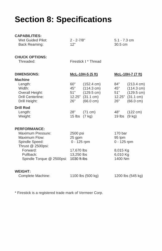
Section 8: Specifications
CAPABILITIES:
Wet Guided Pilot: 2 - 2-7/8" 5.1 - 7.3 cm Back Reaming: 12" 30.5 cm
CHUCK OPTIONS:
Threaded: Firestick I * Thread
DIMENSIONS: McL-10H-5 (5 ft) McL-10H-7 (7 ft)
Machine
Length: 60" (152.4 cm) 84" (213.4 cm) Width: 45" (114.3 cm) 45" (114.3 cm) Overall Height: 51" (129.5 cm) 51" (129.5 cm) Drill Centerline: 12.25" (31.1 cm) 12.25" (31.1 cm) Drill Height: 26" (66.0 cm) 26" (66.0 cm)
Drill Rod
Length: 28" (71 cm) 48" (122 cm) Weight: 15 lbs (7 kg) 19 lbs (9 kg)
PERFORMANCE:
Maximum Pressure: 2500 psi 170 bar Maximum Flow: 25 gpm 95 lpm Spindle Speed: 0 - 125 rpm 0 - 125 rpm Thrust @ 2500psi:
Forward: 17,670 lbs 8,015 Kg Pullback: 13,250 lbs 6,010 Kg Spindle Torque @ 2500psi: 1030 ft-lbs 1400 Nm
WEIGHT:
Complete Machine: 1100 lbs (500 kg) 1200 lbs (545 kg)
* Firestick is a registered trade mark of Vermeer Corp.

McLaughlin Group, Inc. 2006 Perimeter Road
Greenville, SC 29605 U.S.A.
Toll free: 800-435-9340 World Wide: 864-277-5870 Fax: 864-235-9661
Email: [email protected]
Website: www.mightymole.com