MCF DUST FILTER - Bid on Equipmentbidonequipment.info/s/MAC EQUIPMENT, INC. Dust... · Publication:...
23
Publication: MAN3001E Revision Date: 11/10/05 MAC EQUIPMENT, INC. P.O. BOX 205 SABETHA, KS 66534 SALES, PARTS & SERVICE: 1-888-821-2476 www.macequipment.com MCF DUST FILTER INSTALLATION, OPERATION & MAINTENANCE MANUAL
Transcript of MCF DUST FILTER - Bid on Equipmentbidonequipment.info/s/MAC EQUIPMENT, INC. Dust... · Publication:...
Publication: MAN3001E Revision Date: 11/10/05
MAC EQUIPMENT, INC.P.O. BOX 205
SABETHA, KS 66534
SALES, PARTS & SERVICE: 1-888-821-2476www.macequipment.com
MCF DUST FILTER
INSTALLATION, OPERATION
& MAINTENANCE MANUAL
pdfMachine by Broadgun Software - a great PDF writer! - a great PDF creator! - http://www.pdfmachine.com http://www.broadgun.com
TABLE OF CONTENTS
DESCRIPTION PAGE
General Introduction.................................................................. 1
Safety......................................................................................... 1
Principle of Operation................................................................ 3
Installation.................................................................................. 4
System Start-Up & Operation ................................................... 12
Maintenance .............................................................................. 12
Troubleshooting......................................................................... 18
Spare Parts................................................................................ 19
LIST OF FIGURES Page
Figure 1-1 Typical MCF Dust Filter.......................................... 1
Figure 2-1 Lockout and Tagout of
Electrical Service and Compressed Air .................. 1
Figure 2-2 Typical Location of Safety Decals ......................... 2
Figure 2-3 Typical Locations of Safety Decals
For Explosion Vents .............................................. 3
Figure 3-1 Principle of Operation............................................. 3
Figure 4-1 Typical Support Structure....................................... 4
Figure 4-2 Typical High Entry Inlet .......................................... 4
Figure 4-3 Typical Front Access Service
Platform and Ladder Assembly.............................. 5
Figure 4-4 Typical Side and Front Access
Service Platform and Ladder Assembly................. 5
Figure 4-5 Typical PVC Style Explosion Vent......................... 5
Figure 4-6 Typical Rupture Style Explosion Vent ................... 6
Figure 4-7 Location of Ductwork and Accessories ................. 6
Figure 4-8 Discharge Auger Assembly.................................... 6
Figure 4-9 Pump Package ....................................................... 6
Figure 4-10 Installation of Differential Pressure Gauge.......... 7
Figure 4-11 Jumpers and Wiring of the Photohelic
Switch/Gauge ....................................................... 7
Figure 6-1 Typical Cross Section of Cleaning Mechanism.. 13
Figure 6-2 Typical Distribution Arm Detail............................ 13
Figure 6-3 Typical MCF Index Sensor.................................. 14
Figure 6-4 Typical Alignment Illustration .............................. 14
Figure 6-5 Typical MCF Larger Diaphragm Details ............. 14
Figure 6-6 Typical Tightening Sequence.............................. 15
Figure 9-1 Typical Cleaning Mechanism.............................. 20
It is the owner's responsibility to maintain the safety features included with this equipment. The safetyfeatures may include, but not necessarily be limited to: guards, access doors and covers, explosionvents, warning decals, caution decals, and advisory decals. Replacement safety features are availablefrom MAC Equipment, Inc.
DO NOT attempt to operate this equipment until you have read and understood the contents of thismanual. If you do not understand the contents of the manual bring it to the attention of yoursupervisor. This manual contains important safety instructions concerning the maintenance, use,and operation of this product. Failure to follow these instructions may result in serious injury ordeath.
NO haga funcionar este equipo hasta haber leido y comprehendido el contenido de este manual. Siaiguna partre del contenido del manual queda sin comprehender, notifiqueselo a su supervisor. Estemanual contiene instrucciones importantes en cuanto al anterimiento, uso, y funcionamiento sequrosde este producto. El no seguir las instrucciones contenidas en este manual podria ocasionar lesionesgraves.

Publication: MAN3001E MAC Equipment, Inc. 1
GENERAL INTRODUCTIONCongratulations on your selection of a MAC MCF Dust Filter. As the owner/operator of this unityou have an important responsibility to see that it is operated and maintained in a safe manner.The unit will require very little attention to keep it in good operating condition. This manual hasbeen prepared to aid you in that effort.
Throughout this manual, reference may be made to various components which may or may not bepart of your particular system. They are included in the interest of fully describing typical MCFfilter systems.
Figure 1-1 Typical MCF Dust Filter
Receiving Your EquipmentAs soon as the equipment is received, it should be carefully inspected to make certain the unit isin good condition and all items listed on the packing list are received. Even though the equipmentis mounted on heavy shipping skids at our plant it is possible for it to be damaged in shipment. Alldamages or shortages should be noted on the Bill of Lading. The purchaser must take immediatesteps to file reports and damage claims with the carrier. All damages incurred to the unit in transitare the responsibility of the common carrier since it is the policy of MAC Equipment, Inc. to makeshipment F.O.B. from its factory. Ownership passes to purchaser when the unit is loaded andaccepted by carrier. Any claims for in transit damage or shortage must be brought against thecarrier by the purchaser.
If the unit is not going to be assembled and installed soon after arrival, it should be stored in awarm, dry location to protect against corrosion. Filter bags and cages or cartridges must bestored in a dry, rodent proof location.
SAFETY INFORMATION
Recognize Safety Information
Understand Signal WordsDANGER !Indicates an imminently hazardous situation which, if not avoided, will result in death or seriousinjury.WARNING !Indicates a potentially hazardous situation which, if not avoided, could result in death or seriousinjury.CAUTION !Indicates a potentially hazardous situation which, if not avoided, may result in minor or moderateinjury and/or property damage.
Warning Decals And GuardsThis piece of equipment contains several warning decals located in many different locations. It isthe owner/operator�s responsibility to maintain the integrity of these decals and to ensure that alloperators of the equipment are aware of them and understand their meaning. Replacementdecals are available free of charge from your MAC Equipment Service Representative, or bycalling MAC Equipment Inc. at 1-888-821-2476.This piece of equipment may contain one or more safety guards to protect the operator(s) frominjury. It is the owner/operator�s responsibility to maintain the integrity of these guards and ensurethat they are in place when the equipment is in operation.
Lockout-Tagout Requirements
ELECTRICAL POWER COMPRESSED AIR OR GASFigure 2-1 Lockout and Tagout of Electrical Service and Compressed Air (or other gas)
Control of this equipment must be in accordance with OSHA Standard 1910.147 "The control ofhazardous energy (lockout-tagout)". This standard "requires employers to establish a programand utilize procedures for affixing appropriate lockout devices or tagout devices to energy isolatingdevices and to otherwise disable machines or equipment to prevent unexpected energizing, start-up or release of stored energy in order to prevent injury to employees".For further information on Lockout-Tagout requirements, see your company's Safety Director orrefer to OSHA Standard 1910.147.
Safety Precautions
Guards, access doors, and covers are in place and secure.
The equipment has been wired and grounded in accordance with all applicable codes.
If air being filtered contains toxic materials all necessary precautions to protect personnelhave been taken.
An approved lockout-tagout procedure has been followed before the equipment isinspected, disassembled, and/or serviced. The equipment is automatically controlled andmay start without warning unless energy supplies are properly disconnected and lockedout-tagged out.
The control panel enclosure is closed and secured except as is necessary for service oradjustment.
The service door is closed and secured. Do not enter filter while the system exhaust fan isoperating; air flow can pull service door closed, trapping personnel inside.
A confined space permit, if required by authorities having jurisdiction, has been obtainedprior to personnel entering the unit. Check with your company�s safety director for specialinstructions, testing prior to entry, etc. that may be required by the specific application.
Do not attempt to operate or maintain thispiece of equipment until you have read andthoroughly understood all of the safetyinformation contained in this manual. All suchinformation must be taken seriously. Thispiece of equipment contains moving parts andpotential pinch points which can cause seriousinjury or death. If you do not understandanything in this manual seek assistance fromyour supervisor before operating thisequipment.
WARNING!
The symbol at left is used to alert you to importantsafety messages located throughout this manual. Italso appears on the equipment to alert you topotential hazards. When you see this symbol youmust read, understand, and heed the informationthat accompanies it.
DO NOT attempt to operate this equipment with anyguard removed. Replace damaged guards.
Before inspecting or servicing this equipmentperform an approved lockout-tagout procedure onthe electrical service, the compressed air (or othergas) supply, or any other energy source.
Do not operate, inspect, or service this equipmentunless all the following safety precautions are ineffect:
Publication: MAN3001E MAC Equipment, Inc. 2
Explosion vents have been properly installed and ducted, as described below in theInstallation section. MAC PVC style explosion vents are shipped (when ordered) with (4)steel bolts. These bolts must be replaced with special plastic bolts before operating thefilter.
Do not cut, weld or grind on the filter while it is in operation; dust laden air may be highlyexplosive. Refer to the proper National Fire Protection Association Manual for informationon cutting, welding or grinding in hazardous areas.
The work area is clean and orderly, free of debris, materials, tools, etc.
Operating personnel are wearing proper ear and eye protection and have secured loosehair, clothing, jewelry, etc.
Installation and Operation Cautions The MCF Cleaning arm timing is critical to the correct and efficient operation of these filters.
Refer to the maintenance section for correct placement and adjustment of the timing.
BLOWERS and GEAR BOXES are shipped without lubrication oil, do not operatebefore lubricating. Refer to the maintenance section for the lubrication schedule.
All system piping must be clean internally before connecting to blower.
Check lubrication level only when the equipment is stopped.
Keep inlet filter clean.
Keep belts properly tensioned and aligned.
Keep pressure relief valves in good condition so that maximum pressure is not exceeded.
Never attempt to regulate air flow by restricting intake or exhaust of a positive displacementblower.
NOTE: Full rated pressure is full pressure differential from inlet flange to discharge flange.
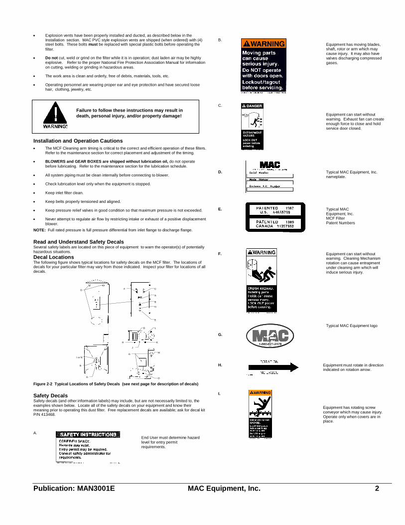
Read and Understand Safety DecalsSeveral safety labels are located on this piece of equipment to warn the operator(s) of potentiallyhazardous situations.
Decal LocationsThe following figure shows typical locations for safety decals on the MCF filter. The locations ofdecals for your particular filter may vary from those indicated. Inspect your filter for locations of alldecals.
Figure 2-2 Typical Locations of Safety Decals (see next page for description of decals)
Safety DecalsSafety decals (and other information labels) may include, but are not necessarily limited to, theexamples shown below. Locate all of the safety decals on your equipment and know theirmeaning prior to operating this dust filter. Free replacement decals are available; ask for decal kitP/N 413468.
A.End User must determine hazardlevel for entry permitrequirements.
B.Equipment has moving blades,shaft, rotor or arm which maycause injury. It may also havevalves discharging compressedgases.
C.
Equipment can start withoutwarning. Exhaust fan can createenough force to close and holdservice door closed.
D. Typical MAC Equipment, Inc.nameplate.
E. Typical MACEquipment, Inc.MCF FilterPatent Numbers
F. Equipment can start withoutwarning. Cleaning Mechanismrotation can cause entrapmentunder cleaning arm which willinduce serious injury.
G.
Typical MAC Equipment logo
H. Equipment must rotate in directionindicated on rotation arrow.
I.
Equipment has rotating screwconveyor which may cause injury.Operate only when covers are inplace.
Failure to follow these instructions may result indeath, personal injury, and/or property damage!
G
I or N
B
G
G
O
M
K
J
H
D
E
D
B
A
CF
L
Publication: MAN3001E MAC Equipment, Inc. 3
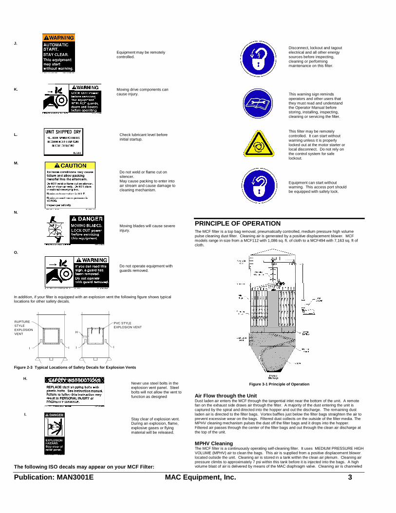
J.
Equipment may be remotelycontrolled.
K. Moving drive components cancause injury.
L. Check lubricant level beforeinitial startup.
M.
Do not weld or flame cut onsilencer.May cause packing to enter intoair stream and cause damage tocleaning mechanism.
N.
Moving blades will cause severeinjury.
O.
Do not operate equipment withguards removed.
In addition, if your filter is equipped with an explosion vent the following figure shows typicallocations for other safety decals.
PVC STYLEEXPLOSION VENT
RUPTURESTYLEEXPLOSIONVENT
I I I I
H
Figure 2-3 Typical Locations of Safety Decals for Explosion Vents
H.Never use steel bolts in theexplosion vent panel. Steelbolts will not allow the vent tofunction as designed
I.Stay clear of explosion vent.During an explosion, flame,explosive gases or flyingmaterial will be released.
The following ISO decals may appear on your MCF Filter:
Disconnect, lockout and tagoutelectrical and all other energysources before inspecting,cleaning or performingmaintenance on this filter.
This warning sign remindsoperators and other users thatthey must read and understandthe Operator Manual beforestoring, installing, inspecting,cleaning or servicing the filter.
This filter may be remotelycontrolled. It can start withoutwarning unless it is properlylocked out at the motor starter orlocal disconnect. Do not rely onthe control system for safelockout.
Equipment can start withoutwarning. This access port shouldbe equipped with safety lock.
PRINCIPLE OF OPERATIONThe MCF filter is a top bag removal, pneumatically controlled, medium pressure high volumepulse cleaning dust filter. Cleaning air is generated by a positive displacement blower. MCFmodels range in size from a MCF112 with 1,086 sq. ft. of cloth to a MCF494 with 7,163 sq. ft ofcloth.
Figure 3-1 Principle of Operation
Air Flow through the UnitDust laden air enters the MCF through the tangential inlet near the bottom of the unit. A remotefan on the exhaust side draws air through the filter. A majority of the dust entering the unit iscaptured by the spiral and directed into the hopper and out the discharge. The remaining dustladen air is directed to the filter bags. Vortex baffles just below the filter bags straighten the air toprevent excessive wear on the bags. Filtered dust collects on the outside of the filter media. TheMPHV cleaning mechanism pulses the dust off the filter bags and it drops into the hopper.Filtered air passes through the center of the filter bags and out through the clean air discharge atthe top of the unit.
MPHV CleaningThe MCF filter is a continuously operating self-cleaning filter. It uses MEDIUM PRESSURE HIGHVOLUME (MPHV) air to clean the bags. This air is supplied from a positive displacement blowerlocated outside the unit. Cleaning air is stored in a tank within the clean air plenum. Cleaning airpressure climbs to approximately 7 psi within this tank before it is injected into the bags. A highvolume blast of air is delivered by means of the MAC diaphragm valve. Cleaning air is channeled
Publication: MAN3001E MAC Equipment, Inc. 4
to the bags through a rotating arm. The cleaning arm has a series of nozzles correlated to thetube sheet layout. Cleaning air exits these nozzles and enters the bags. This action cleans thebags by; (1) creating a shock wave that pops the bag, and (2) forcing a momentary reverse flowof air through the bags.
MCF TimingThe unique feature of the MCF filter is its patented timing mechanism. Once adjusted, this deviceassures a blast of cleaning air is injected directly into the center of the bag, regardless of therotational speed of the cleaning arm. This device is mechanical and does not require electricalpower to internal solenoids for firing. Through the proper selection of gear ratios and rotationalspeeds the cleaning frequency can be adjusted.
Positive Displacement BlowerThe MCF Filter requires a rotary positive displacement blower to supply the cleaning air. Thisblower has two figure-eight impellers rotating in opposite directions. As the impeller lobes passthe blower inlet, they trap a quantity of air. This entrapment occurs four times per revolution,moving the entrained air around the case to the blower outlet. Timing gears accurately positionthe impellers in relation to each other, maintaining the minute clearances so vital to the highvolumetric efficiency of the rotary positive displacement blower. For further information on thisequipment refer to the appendix.
Variable Cleaning Control Options: Air Diverter ValveThe Air Diverter Valve (ADV) cleaning cycle control is offered as an option on the MAC MCFfilters. This valve provides an economical method of controlling the cleaning cycle of the filter.The cleaning cycle can be extend from the base time to any cycle time desired above this base.This is useful for filter applications that require a longer duration between cleaning pulses, toprevent over-cleaning the filter media.To extend the cleaning cycle with the ADV, a timer, Photohelic gauge, or PLC is required. TheADV functions as a by-pass valve to the cleaning system. To initiate cleaning the valve is closedand air is allowed to flow to the cleaning mechanism. The valve is left closed for the duration ofone cleaning cycle. To interrupt the cleaning cycle the valve is opened and cleaning air isexhausted to the atmosphere. The frequency of the cleaning cycle is controlled by adjusting theduration of the open state of the valve.
Variable Frequency DrivesVariable Frequency Drives (VFD) are offered as an alternate option for cleaning-cycle control onthe MAC MCF Filters. This arrangement controls the speed of the rotating cleaning arm andblower, which directly controls the frequency of the cleaning cycle. Cleaning frequency, isadjustable above and below the base cycle. The extent of control is limited by the physicallimitations of the drive and the motor. With this type of control, the filter is usually provided with anon-standard base cleaning cycle, falling in the center of the desired adjustment range. Refer toMAC Engineering Department for further details.
Air ExhaustReturning filtered exhaust air into a facility can present hazards. The type of dust, it�scharacteristics and the effect of a recirculation system malfunction must be considered. If systemdesign dictates that filtered air be returned into the facility, the buyer is cautioned to takeappropriate steps to monitor the air quality and provide appropriate safeguards as prescribed byOSHA, NFPA, Federal, State and Local codes and regulations.
INSTALLATIONThe MCF filter housing and internal components are shipped factory assembled. The supportstructure (if provided), magnehelic or photohelic pressure gauges, bags and cages, serviceplatform and ladder/safety cage are shipped loose and require field assembly.
LocationLocate the MCF filter in a clear area away from normal personnel traffic on a flat and solidconcrete or steel surface. Locate the filter so as to minimize supply and exhaust ductwork and sothat explosion venting, if required, can be directed so that injury to personnel and damage toproperty cannot occur. Provide sufficient space for emptying the hopper and maintaining theunit.
FoundationThe filter requires an adequate foundation, designed by a qualified structural engineer. Refer tothe General Dimension drawings of your system for foot pad layout and weights. Whencalculating the loading for the foundation, the weight of the filter, material collected, and allauxiliary equipment must be considered together with snow, wind and seismic loads.
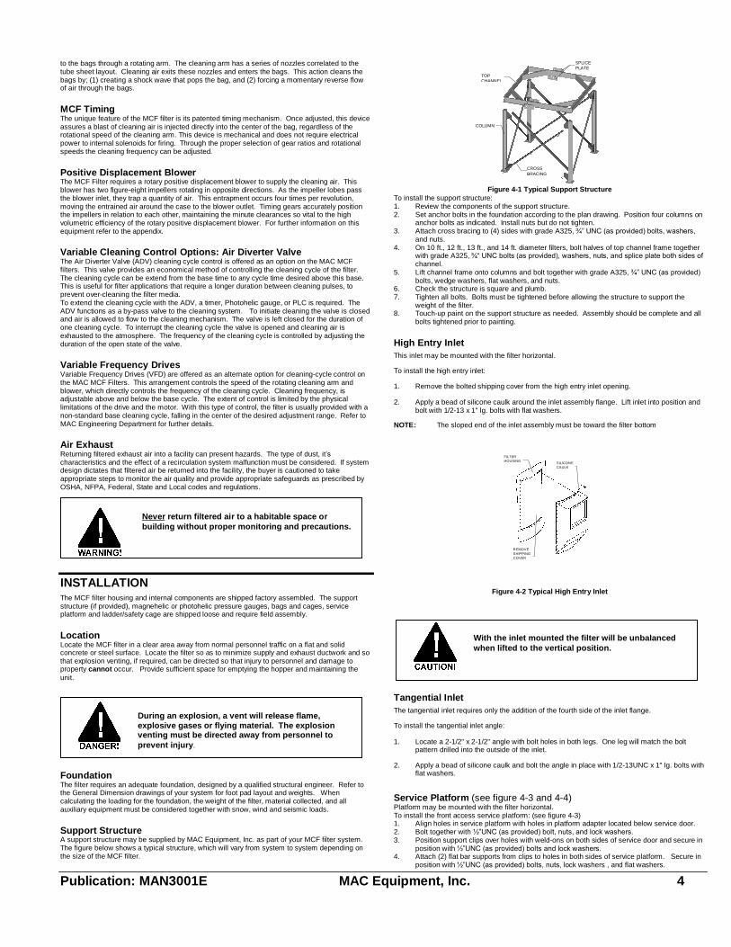
Support StructureA support structure may be supplied by MAC Equipment, Inc. as part of your MCF filter system.The figure below shows a typical structure, which will vary from system to system depending onthe size of the MCF filter.
TOPCHANNEL
SPLICEPLATE
COLUMN
CROSSBRACING
Figure 4-1 Typical Support StructureTo install the support structure:1. Review the components of the support structure.2. Set anchor bolts in the foundation according to the plan drawing. Position four columns on
anchor bolts as indicated. Install nuts but do not tighten.3. Attach cross bracing to (4) sides with grade A325, ¾� UNC (as provided) bolts, washers,
and nuts.4. On 10 ft., 12 ft., 13 ft., and 14 ft. diameter filters, bolt halves of top channel frame together
with grade A325, ¾� UNC bolts (as provided), washers, nuts, and splice plate both sides ofchannel.
5. Lift channel frame onto columns and bolt together with grade A325, ¾� UNC (as provided)bolts, wedge washers, flat washers, and nuts.
6. Check the structure is square and plumb.7. Tighten all bolts. Bolts must be tightened before allowing the structure to support the
weight of the filter.8. Touch-up paint on the support structure as needed. Assembly should be complete and all
bolts tightened prior to painting.
High Entry InletThis inlet may be mounted with the filter horizontal.
To install the high entry inlet:
1. Remove the bolted shipping cover from the high entry inlet opening.
2. Apply a bead of silicone caulk around the inlet assembly flange. Lift inlet into position andbolt with 1/2-13 x 1" lg. bolts with flat washers.
NOTE: The sloped end of the inlet assembly must be toward the filter bottom
Figure 4-2 Typical High Entry Inlet
Tangential InletThe tangential inlet requires only the addition of the fourth side of the inlet flange.
To install the tangential inlet angle:
1. Locate a 2-1/2" x 2-1/2" angle with bolt holes in both legs. One leg will match the boltpattern drilled into the outside of the inlet.
2. Apply a bead of silicone caulk and bolt the angle in place with 1/2-13UNC x 1" lg. bolts withflat washers.
Service Platform (see figure 4-3 and 4-4)Platform may be mounted with the filter horizontal.To install the front access service platform: (see figure 4-3)1. Align holes in service platform with holes in platform adapter located below service door.2. Bolt together with ½�UNC (as provided) bolt, nuts, and lock washers.3. Position support clips over holes with weld-ons on both sides of service door and secure in
position with ½�UNC (as provided) bolts and lock washers.4. Attach (2) flat bar supports from clips to holes in both sides of service platform. Secure in
position with ½�UNC (as provided) bolts, nuts, lock washers , and flat washers.
REMOVESHIPPINGCOVER
FILTERHOUSING
SILICONECAULK
Never return filtered air to a habitable space orbuilding without proper monitoring and precautions.
During an explosion, a vent will release flame,explosive gases or flying material. The explosionventing must be directed away from personnel toprevent injury.
With the inlet mounted the filter will be unbalancedwhen lifted to the vertical position.

Publication: MAN3001E MAC Equipment, Inc. 5
To install the side access service platform: (see figure 4-4)1. Align holes in service platform with holes in platform adapter located below service door.2. Bolt together with ½�UNC (as provided) bolt, nuts, and lock washers.3. Position support clip over holes with weld-ons below platform adapter and secure in
position with ½�UNC (as provided) bolts and lock washers.4. Attach (2) angle supports from clips to angles on bottom side of service platform. Secure
in position with ½�UNC (as provided) bolts, nuts, lock washers , and flat washers.
Setting in PlaceIt is recommended that a properly sized crane be used for unloading the filter and setting it inplace.
To set up the MCF filter:
1. Lift the filter housing and set in place on the support structure. Bolt the filter to the structurewith 5/8" UNC (as provided) bolts, lock washers, flat washers, wedge washers, and nuts.Tighten all bolts before removing the crane.
Ladder, Safety Cage, and Ladder Stand-offLadder and safety cages will come in pre-assembled 6 ft., 4 ft., or 3 ft. lengths and (1) 8 ft. sectionwithout a safety cage attached.
To assemble ladder and safety cages: (see figure 4-3)
1. Position ladder and safety cage assemblies on ground end to end with the entry section ateither end. (Note: If ladder rungs are not 12� apart flip section end for end).
2. Join ladder side rails together with splice plate (as provided), 3/8� UNC bolts, and locknuts3. Join lower safety cage bars to upper safety cage hoop using 3/8� UNC bolts and locknuts.
(Note: safety bars should be on the inside of safety hoop.)4. After all sections are joined together lift ladder into position and attach to service platform.5. Position stand-off clips over holes with weld-ons located below service door and secure in
position with ½�UNC (as provided) bolts and lockwashers.6. Attach ladder stand-off to clips with ½�UNC (as provided) bolts, nuts, and flatwashers.
Level stand-off and clamp to ladder rail. Pilot drill through hole in stand-off into ladder railon both sides. Secure stand-off to ladder rail with ½�UNC (as provided) bolts, nuts, andflatwashers. (Note: Stand-off to ladder connection can be welded or bolted.)
7. Measure distance from bottom of ladder rung to ground. Cut 8 ft. section to this length.(Note: Check to make sure what end will maintain the 12� distance from rung to rung andcut the opposite end). Join ladder side rails together as described in step #2.
8. Position ladder foundation clip by clamping to the bottom of the ladder rail and pilot drillthrough (2) holes in foundation clip into ladder rail on both sides. Secure stand-off to railwith 3/8� UNC (as provided) bolts and locknuts. Secure foundation clip to ground. (Note:Foundation clips to ladder connection can be welded or bolted.)
SERVICEPLATFORM
SUPPORTCLIP
FLAT BARSUPPORT
PLATFORMADAPTER
SUPPORTCLIP
LADDERSTAND-OFF
LADDER/CAGEASSEMBLY
ENTRYSECTION
SPLICEPLATE
FOUNDATIONCLIP
8 FT LADDERSECTION
Figure 4-3 Typical Front Access Service Platform and Ladder Assembly
SIDE ACCESSSERVICE PLATFORM
PLATFORMADAPTER
ENTRYSECTION
ANGLESUPPORT
SUPPORTCLIP
LADDERSTAND-OFF
FRONT ACCESSSERVICE PLATFORM
SUPPORTCLIP
FLAT BARSUPPORT
PLATFORMADAPTER
SPLICEPLATE
FOUNDATIONCLIP
8 FT LADDERSECTION
Figure 4-4 Typical Side and Front Access Service Platform and Ladder Assembly
Explosion VentingVenting GuidelinesThis section is intended as a general guide only: For further information refer to NFPA Standard68, "Explosion Venting" and consult with your insurance carrier.
Explosion venting is required whenever the filter will process explosive dustsas defined by NFPA.
Dust filters handling explosive dusts should be located outside of buildingswherever possible.
Explosion vents must not be obstructed in any way and must be protected fromsnow/ice buildup. Explosion vents must be oriented so that flame, explosivegases, or flying material cannot injure personnel or damage property.
Dust filters inside of buildings should be located next to an exterior wall; theexplosion vent(s) must be ducted to the outside of the building. Vent ductsmust be kept as short and straight as possible, avoiding bends. Such ductsmust be capable of withstanding a pressure at least as high as that expected todevelop inside the filter itself in the event of an explosion. Ducts increaseinternal pressures inside the filter, and special reinforcement of the filter maybe required. Consult MAC Equipment, Inc. Engineering Department regardingyour specific application.
Any duct will decrease the effectiveness of the vent.
Explosion Vents-GeneralExplosion vents are available from MAC Equipment Inc., in either PVC or domed rupture panelstyles as part of the filter system. The PVC style vent functions by breaking the plastic boltsholding it to the filter housing. The rupture panel style functions by bursting the panel itself.Explosion vents are installed after the filter unit is assembled on its support structure.
Installing MAC PVC Style VentsThe filter is shipped with the PVC style explosion vent panel temporarily mounted with four steelbolts. The vent must be disassembled and re-installed using the plastic bolts provided.Refer to Figure 4-5.
Figure 4-5 Typical PVC Style Explosion Vent1. Remove the four steel bolts and discard. Remove the vent panel.2. Seal the housing with the 1/8" thick x 1-1/2" wide sponge gasket, supplied.3. Bolt vent panel in place with 3/8" plastic bolts provided by MAC Equipment, Inc. Torque
to approximately 30 inch-pounds.4. Make sure that the two retaining chains are tightly fastened to the housing and to the vent
panel.
Be sure that all bolts are MAC supplied plastic.NEVER USE STEEL BOLTS IN THE EXPLOSIONVENT PANEL. Steel bolts will not allow the vent tofunction as designed, and could result in injury topersonnel and considerable damage to the filter inthe event of an explosion.
Spreader bars are recommended to distribute theload evenly while lifting the filter.
Publication: MAN3001E MAC Equipment, Inc. 6
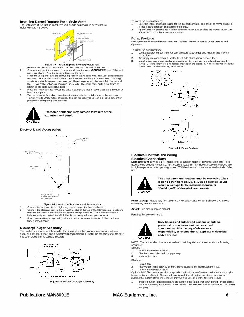
Installing Domed Rupture Panel Style VentsThe installation of the rupture panel style vent should be performed by two people.Refer to Figure 4-6 below.
RUPTURE STYLE VENT PANEL
MOUNTING BOLTS
VENT OPENING IN FILTER HOUSING
VENT I. D. TAG
HOLDDOWN FRAME
VENT MOUNT
V-NOTCH
Figure 4-6 Typical Rupture Style Explosion Vent1. Remove the hold-down frame from the vent mount on the side of the filter.2. Carefully remove the rupture style vent panel from the crate (CAUTION! Edges of the vent
panel are sharp!) Avoid excessive flexure of the vent.3. Place the vent panel over the protruding bolts in the housing wall. The vent panel must be
oriented correctly. The panel ruptures on three sides and hinges on the fourth. The hingeside is indicated by a v-notch in the edge. Place the panel with the v-notch to the left andthe I.D. tag at the bottom as shown in Figure 4-6. The dome must protrude outward asshown or the panel will not function.
4. Place the hold down frame over the bolts, making sure that an even pressure is brought tobear on the panel.
5. Tighten nuts evenly and use an alternating pattern to prevent damage to the vent panel.Tighten nuts to 20-25 ft. lbs. of torque. It is not necessary to use an excessive amount ofpressure to clamp the panel securely.
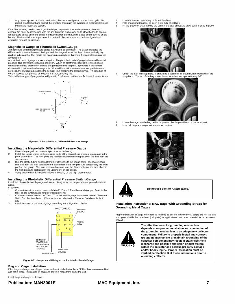
Ductwork and Accessories
Figure 4-7 Location of Ductwork and Accessories1. Connect the inlet duct to the high entry inlet or tangential inlet on the filter.2. Connect the clean air duct to the exhaust located at the top of the filter housing. Ductwork
must be constructed to withstand the system design pressure. The ductwork must beindependently supported; the MCF filter is not designed to support ductwork.
3. Attach any auxiliary equipment (such as an airlock or screw conveyor) to the dischargeflange of the hopper.
Discharge Auger AssemblyThe discharge auger assembly includes transitions with bolted inspection opening, dischargeauger and optional airlock, and is typically shipped assembled. Install the assembly after the filterhas been erected on its support structure
.
Figure 4-8 Discharge Auger Assembly
To install the auger assembly:1. Determine the correct orientation for the auger discharge. The transition may be rotated
through 360 degreesin 15 degree increments.2. Apply a bead of silicone caulk to the transition flange and bolt it to the hopper flange with
3/8-16UNC x 1-1/4 bolts with lock washers.
Pump PackagePump package is shipped without lubricant. Refer to lubrication section under Start-up andOperation.
To install the pump package:1. Locate package on concrete pad with pressure (discharge) side to left of ladder when
facing filter.2. Air supply line connection is located to left side of and above service door.3. Install piping from pump discharge silencer to filter (piping is normally not supplied by
MAC). Be sure that there is no foreign material in the piping. Dirt and scale will effect theoperation of the filter cleaning mechanism.
Figure 4-9 Pump Package
Electrical Controls and WiringElectrical ConnectionsDistributor arm: Drive is a 1 HP motor (refer to label on motor for power requirements). It isaccessible to conduit through a 1" NPT coupling located in filter sidewall above the service door.In high temperature units operating above 165oF the drive and motor are located outside of theunit.
Pump package: Motors vary from 2 HP to 15 HP, all are 230/460 volt 3 phase 60 Hz unlessspecifically ordered otherwise.
Airlock: See airlock service manual.
Fan: See fan service manual.
NOTE: The motors should be interlocked such that they start and shut-down in the followingsequence:Start-up:1. Airlock and discharge auger.2. Distributor arm drive and pump package.3. Main system fan.
Shut-down:
1. System fan.2. After variable time delay (0-15 min.) pump package and distributor arm drive.3. Airlock and discharge auger.Optional MCF filter control panel is designed to make the task of start-up and shut-down simpler,faster, and more efficient. The control logic is such that all motors are started in order bypushing the system start button and will stay running until one of the following occur:
1. The stop button is depressed and the system goes into a shut down period. The main fanstops immediately and the rest of the system continues to run for an adjustable time beforestopping.
HIGH ENTR YINLET
CLE AN AIRDUC T
TAN GENTIALINLET
A IRLO CK ORO THER OUTPUTA CCES SORY
Excessive tightening may damage fasteners or theexplosion vent panel.
Only trained and authorized persons should bepermitted to service or maintain electricalcomponents. It is the buyer�s/installer�sresponsibility to ensure that all applicable electricalcodes are met.
The distributor arm rotation must be clockwise whenlooking down from above. Reverse operation couldresult in damage to the index mechanism or"Backing-off" of threaded components.
Publication: MAN3001E MAC Equipment, Inc. 7
2. Any one of system motors is overloaded, the system will go into a shut down cycle. Torestart, troubleshoot and correct the problem, then push the overloaded motor starter resetbutton and restart the system.
If the filter is being used to vent a gas fired dryer, to prevent fires and explosions, the mainexhaust fan must be interlocked with the gas burner in such a way as to allow the fan to operatean adequate period of time to purge the dust collector of combustible gases before turning on theburner. The installation of a gas detection device in the system should be investigated andevaluated for each application.
Magnehelic Gauge or Photohelic Switch\GaugeA magnehelic differential pressure gauge is available as an option. The gauge indicates thedifference in pressure between the input and discharge sides of the filter. An excessively highreading indicates that filter media are becoming clogged and that more frequent cleaning pulsesare required.A photohelic switch/gauge is a second option. The photohelic switch/gauge indicates differentialpressure and controls the cleaning operation. When an electronic circuit in the switch/gaugedetects differential pressure in excess of a predetermined set point, it provides a dry contactclosure which initiates the cleaning cycle. When differential pressure drops to a predeterminedset point, the switch/gauge opens the contact, thus stopping the cleaning cycle. This method ofcontrol reduces compressed air needed and increases bag life.To install either type of gauge refer to Figure 4-10 below and to the manufacturers documentation.
Figure 4-10 Installation of Differential Pressure Gauge
Installing the Magnehelic Differential Pressure Gauge1. Mount the gauge in a convenient place for easy viewing.2. Install the tubing fittings in the pressure ports of the magnehelic pressure gauge and in the
ports on the filter. The filter ports are normally located on the right side of the filter from theservice door.
3. Run the plastic tubing supplied from the filter ports to the gauge ports. The low pressureline runs from the filter port above the tube sheet to the low pressure port (usually the lowerport) on the gauge. The high pressure line runs from the filter port below the tube sheet tothe high pressure port (usually the upper port) on the gauge.
4. Verify that the filter is installed inside the housing on the high pressure port.
Installing the Photohelic Differential Pressure Switch/GaugeInstall the photohelic switch/gauge and run air piping as for the magnehelic gauge as describedabove.In addition:1. Connect electric power to contacts labeled �L1� and �L2� on the switch/gauge. Refer to the
label on the switch/gauge for power requirements.2. Connect contacts labeled �NO� and �C� on the switch/gauge to contacts labeled �Pressure
Switch� on the timer board. (Remove jumper between the Pressure Switch contacts, ifany.)
3. Install jumpers on the switch/gauge according to the Figure 4-11 below.
Figure 4-11 Jumpers and Wiring of the Photohelic Switch/Gauge
Bag and Cage InstallationFilter bags and cages are shipped loose and are installed after the MCF filter has been assembledand set in place. Installation of bags and cages is made from inside the unit.
Install bags and cages as follows:
1. Lower bottom of bag through hole in tube sheet.2. Fold snap band (bag top) to insert it into tube sheet hole.3. Fit the groove of snap band to the edge of the tube sheet and allow band to snap in place.
4. Check the fit of the snap band. It should be a secure fit all around with no wrinkles in thesnap band. The top of the bag should be above tubesheet approximately 3/8�.
5. Lower the cage into the bag. When in position the flange will rest on the tubesheet.6. Insert all bags and cages in their proper position.
Installation Instructions: MAC Bags With Grounding Straps forGrounding Metal Cages
Proper installation of bags and cages is required to ensure that the metal cages are not isolatedfrom ground with the tubesheet (cell plate) in applications that have potential for an explosionhazard.
.
Do not use bent or rusted cages.
LOW PRESSU REPORT
HIGH PRESSUREPORT
GAU GE
PHOTOHELIC RED MWJUMPER
TO MOTORSTARTER ONDISTRIBUTORARM & PUMPPACKAGE
HI
LO
N
N
C
J
J2L L
2
WHITEMTW
TO POWERSOURCE
POWER TO COIL
The effectiveness of a grounding mechanismdepends upon proper installation and connection ofthe grounding mechanism to an adequately collectorcomponent. Failure to properly install and connectgrounding mechanism or maintain grounding of thecollector component may result in static electricitydischarge and possible explosion of dust streamwithin the collector and serious property damageand/or bodily injury. Proper installation must beverified per Section B of these instructions prior tooperating collector.
Publication: MAN3001E MAC Equipment, Inc. 8
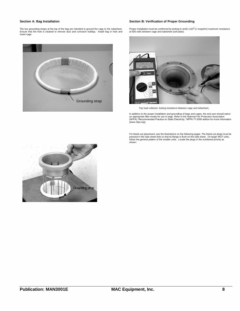
Section A: Bag Installation
The two grounding straps at the top of the bag are intended to ground the cage to the tubesheet.Ensure that the hole is cleaned to remove dust and corrosion buildup. Install bag in hole andinsert cage.
Section B: Verification of Proper Grounding
Proper installation must be confirmed by testing to verify 1x10⁶ (1 megohm) maximum resistanceat 500 volts between cage and tubesheet (cell plate).
In addition to the proper installation and grounding of bags and cages, the end user should selectan appropriate filter media for use in bags. Refer to the National Fire Protection Association(NFPA) �Recommended Practice on Static Electricity,� NFPA 77-2000 edition for more information(www.nfpa.org).
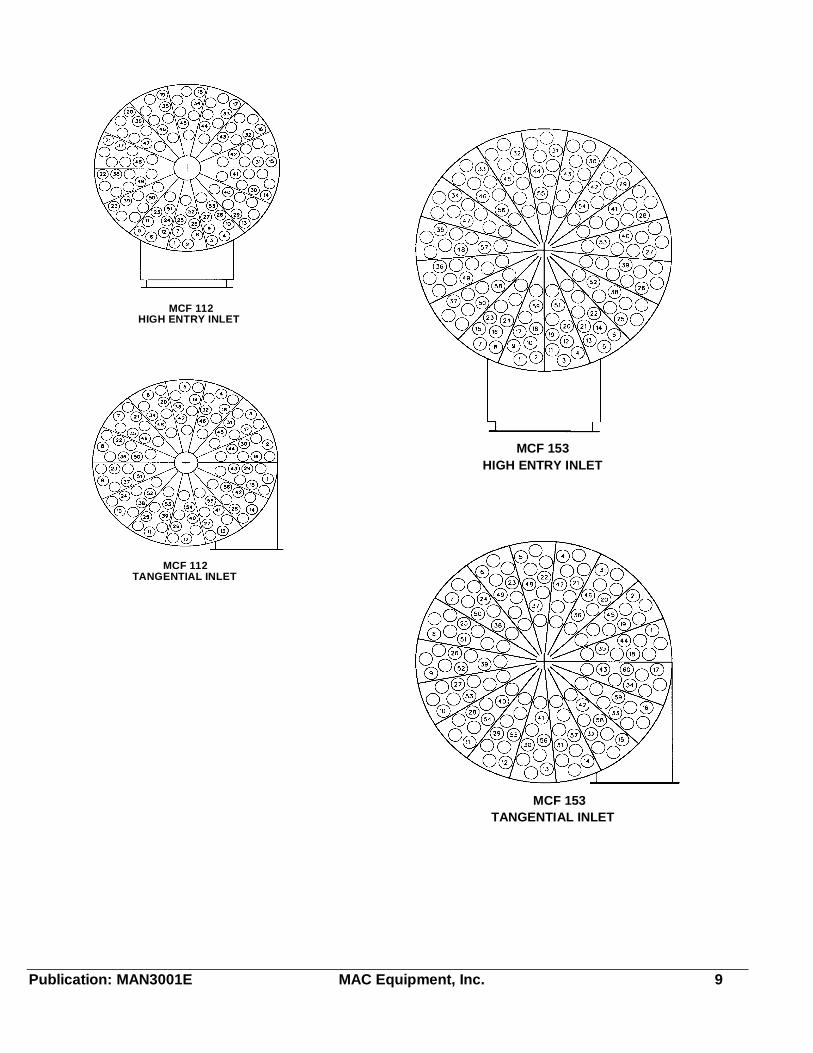
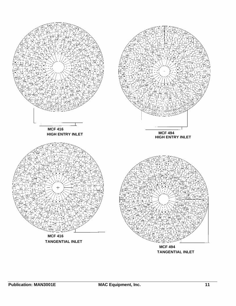
For blank-out placement, see the illustrations on the following pages. The blank-out plugs must bepressed in the tube sheet hole so that its flange is flush on the tube sheet. On larger MCF units,follow the general pattern of the smaller units. Locate the plugs in the numbered priority asshown.
Top load collector: testing resistance between cage and tubesheet.
Grounding strap
Grounding strap
Publication: MAN3001E MAC Equipment, Inc. 9
MCF 112 HIGH ENTRY INLET
MCF 112 TANGENTIAL INLET
MCF 153HIGH ENTRY INLET
MCF 153TANGENTIAL INLET

Publication: MAN3001E MAC Equipment, Inc. 10
MCF 255HIGH ENTRY INLET
MCF 255TANGENTIAL INLET
MCF 361HIGH ENTRY INLET
MCF 361TANGENTIAL INLET
Publication: MAN3001E MAC Equipment, Inc. 11
MCF 416HIGH ENTRY INLET
MCF 416TANGENTIAL INLET
MCF 494HIGH ENTRY INLET
MCF 494TANGENTIAL INLET
Publication: MAN3001E MAC Equipment, Inc. 12
SYSTEM START-UP AND OPERATIONThe following inspection should be made before the initial start-up of the system and for normaloperation thereafter.
Cleaning Mechanism
1. Gear reducer is shipped dry. Install proper level of lubricant. Refer to the LubricationFluids Table for the proper lubricants required for this units.
2. Bearings are pre-lubricated and should not require lubrication at start up.
3. Drive coupling (Item 4) ships disengaged. Loosen set screws and slide couplings together.Tighten set screws. Refer to Figure 9-1 for illustration.
4. Jog the drive motor on and off quickly to check direction of rotation. The proper direction ofthe cleaning arm is CW as viewed from the top. Listen for sounds of unwanted mechanicalcontact.
Pump Package
1. Pump package is shipped dry. Install proper level of lubricant. Refer to the LubricationFluids Table for the proper lubricants required for this units. Refer to the maintenancesection for procedures and quantities of lubricant. Further information is also contained inthe pump package manual.
2. Remove belt guard and check belts for alignment and tension.
3. Rotate pump by hand to check freedom of rotation and binding.
4. Jog the drive motor on and off quickly to check direction of rotation. The proper direction isindicated by a decal on the drive guard. Listen for sounds of unwanted mechanical contact.If pump knocks do not start. See Trouble Shooting Guide.
5. Replace guard.6. Start pump and filter and operate for 15 minutes, check for hot spots, noise and other
indications of interference. Allow pump to cool to room temperature and recheck oil level.7. Start pump and filter. Observe operation for the first hour.
a. Monitor pressure at pump outlet, it should be 6 to 8 PSIG when thefilter pulses.
b. Check amp draw in the motor. See motor name plate for rating.
Pump Operation1. Check oil level daily for first week of use, then weekly thereafter.
2. Check intake filter weekly, or more often if dust conditions are severe. Clean as required.Filter element is a dry type element with a 1/4" polyester foam pre-filter. Pre-filter may becleaned by washing with mild soap and warm water.
3. Check the drive belts tension after 24 hours of operation, then check periodically. Tighten ifnecessary.
Filter Bags1. Check filter bags for proper installation.
2. When the MCF Filter is started up in cold weather or if the unit is handling high temperaturegases there is a danger of condensation forming on the filter bags and inside the housing.This is a very undesirable situation and can be avoided by preheating the filter for about 30minutes. Preheating is accomplished by starting the fan and filter and allowing it to runwithout any dust loading. Before doing this the MCF filter cleaning mechanism and pumppackage should be run alone with the main exhaust fan shut down for about 10 minutes toclean and remove all of the dust cake on the bags.
3. Dust emission may occur from exhaust at start up but it should disappear after a new dustcake is formed on the bags. This should only take a few hours. If the dust emissionpersists, the filter bags should be rechecked to be certain that they seat properly in the tubesheet.
System ParametersUse this page to record the operating conditions of the system once start-up is complete and youhave made the final adjustments. You will find this information very valuable for future referencewhen troubleshooting the system or when monitoring its performance.
DUST MATERIAL:_______________________________
DUST PARTICLE SIZE:______________________________
FILTER MODEL:_______________________________
FILTER S/N:_______________________________
AIR/CLOTH RATIO:________________AIR FLOW_____________ CFM
PHOTOHELIC GAUGE SET POINTS: (if provided)
High:__________"H2O Low:__________"H2O
DIFFERENTIAL PRESSURE:___________"H2O
(after the filter has stabilized)
FAN MODEL/MANUFACTURER:_____________________________
FAN S/N:________________________________
FAN RPM:_________________________________
FAN DESIGN:_______ CFM @_______ "SP, ________ BHP
Notes:
High Temperature UnitsFor MCF units encountering high temperatures in excess of 400 degrees F. the cleaningarm and pump should be operated during the preheat cycle. This will prolong the life oftemperature sensitive materials in the cleaning mechanism by cooling them.
NOTE: AIR DIVERTER VALVES should be in the closed (clean) position during preheat cycles.
MAINTENANCEIt is recommended that one individual be assigned to monitor the operation of the dust-collectionsystem. The individual assigned should have maintenance manuals and manufacturer�sdocumentation for all components readily available. He(she) should be thoroughly familiar withthe manuals so as to be able to pinpoint trouble should it occur.The individual responsible for the system should follow a regular schedule of inspection andmaintenance. The exact schedule will depend on the particular system and the number of hours itoperates per day or week. A typical maintenance schedule is shown below.
Sample Maintenance Schedule
Weekly
1. Check and record magnehelic (or photohelic) gauge readings on all filters. Adverseoperating conditions can be detected by a change in pressure drop.
2. Check for dust in clean air outlet from filter.3. Check filter hoppers for continuous discharge of dust.4. Check fan and motor bearings for excessive heat or vibration.5. If pressure pneumatic conveying equipment is used to dispose of dust, check the positive
displacement pump for vibration, overheating, and proper lubrication. Also, comparereading on the pressure gauge with previous readings. Clean air-inlet filter or replace asnecessary. It is important to follow the manufacturer's recommendation on equipment ofthis nature.
6. Check explosion vent(s) (if provided) for damage (broken bolts or damaged panel).
Monthly (or at manufacturer's recommended intervals)1. Check the filter bags for signs of excessive wear or damage.
Six Months1. Check for evidence of moisture or dust buildup inside the filter housing.
2. Check oil in all gear motors. Do not overfill.
3. Check belt tension on all V-belt drives.
Bag ReplacementThe filter bags are the heart of the filter and need a program of inspection, cleaning, andreplacement to maintain high operating efficiency.
1. Shut down the system, and lockout-tagout the electrical and compressed air service.
2. Remove cage and inspect for rust or damage and replace if necessary.
3. Remove the bag and inspect for excessive wear, replace if necessary.
4. Reinstall clean filter bags as described in the Installation section.
Bag CleaningNatural fiber fabrics (wool or cotton) are subject to shrinkage when wet with water. These fabricsmust be dry cleaned. Synthetic filter fabrics (Orlon, Dacron, Nomex, polypropylene, and Teflon)should also be dry cleaned.
Disconnect and properly lockout-tagout all electricalconnections before performing any inspectionprocedures.
Disconnect and properly lockout-tagout theelectrical and compressed air service beforeperforming any maintenance or service procedureson the filter.
Publication: MAN3001E MAC Equipment, Inc. 13
1. Thoroughly vacuum clean the filter bags to remove the bulk of the dust.
2. Dry clean the bags using a standard dry cleaning procedure. Use pure dry cleaningsolvent. Do not use dry cleaning detergents and/or additives that require the addition ofwater, as these may cause fabric shrinkage.
3. Dry the bags. Drip drying is the recommended drying method. Tumble drying, if used,must be done at low temperatures.
Industrial dry cleaning establishments are available in many cities. These companies specialize infilter bag cleaning and will normally provide the most satisfactory results.
Lubrication
GearmotorsLocated on distributor arm drive and optional airlock drive.Refer to the Lubrication Fluids Table for lubricants. Refer to the Lubrication Schedule forrecommended replacement times. Do not use lubricants containing sulfur and/or chlorine extremepressure additives which are corrosive to worm gear bronze.
MotorsStandard motors are permanently lubricated and require no further attention.
PumpThe positive displacement pump is shipped dry. At the gear end the timing gear teeth arelubricated by being partially submerged. The gear teeth serve as oil slingers for gear endbearings. At the drive end the bearings are grease lubricated.
Filling ProcedureRemove square head vented oil fill plug on gear end. Remove oil level plug located in head plate.Fill gear case until oil drips out of the oil level hole.Add fresh oil as required to maintain proper oil level. In typical 8 hour per day operation, oilshould be drained, flushed and replaced every 6 months, more often with increased operatingtime or severe conditions.Bearings on drive end of blower require grease lubrication initially and every 2 months ofoperation in typical 8 hour days, more often with increased operating time or severe conditions.
Recommended Oil & Grease1. Under ambient temperature operating conditions use any good quality SAE 40 non-
detergent oil.
2. In cold climates use SAE 20 during the winter months.
3. Use No. 2 bearing grease in all climates.
NOTE: For additional information on positive displacement pump consult themanufacturers manual included with pump package.
Lubrication Fluids TableEQUIPMENT AMBIENT
TEMPERATURELUBRICANTT<125OF
MEDIUMTEMPERATURELUBRICANT125<T<225 OF
HIGHTEMPERATURELUBRICANT225<T<475OF
Airlock gearreducer
SEE AIRLOCKMANUAL
NOTRECOMMENDED
NOTRECOMMENDED
Positivedisplacementpump
SEE PUMP MFRLITERATURE
NOTRECOMMENDED
NOTRECOMMENDED
Cleaning ArmDrive
Hub City Gear Lu-bricant GL-1508-58-00-01-010
Hub City All-Tem-perature SyntheticGear Lubricant8-58-00-01-011
NOTRECOMMENDED
CleaningMechanismLower Bearing
NO 2 Bearinggrease
DOW BR2-PLUSMULTIPURPOSEE.P. GREASE
DOW 41 EXTREMEHIGHTEMPERATUREGREASE
Lubrication ScheduleCOMPONENT TOBE SERVICED
DAILY SERVICE
AMBIENTOPERATION
8 HOURS 16 HOURS 24 HOURS
PUMP 26 WEEKS 13 WEEKS 8 WEEKS
PUMP BEARINGS 9 WEEKS 4 - WEEKS 3 WEEKS
GEAR BOXES(INTERNAL)
6 MONTHS 22 WEEKS 14 WEEKS
BEARINGS YEARLY 8 MONTHS 6 MONTHSHIGHTEMPERATUREOPERATION 150 TO250OF
GEAR BOXES(INTERNAL)
16 WEEKS 12 WEEKS 8 WEEKS
GEAR BOXES(EXTERNAL)
6 MONTHS 22 WEEKS 14 WEEKS
BEARINGS 16 WEEKS 12 WEEKS 8 WEEKSHIGHTEMPERATUREOPERATION 250 TO450oF
GEAR BOXES(INTERNAL)
12 WEEKS 8 WEEKS 4 WEEKS
GEAR BOXES(EXTERNAL)
6 MONTHS 22 WEEKS 14 WEEKS
BEARINGS 12 WEEKS 8 WEEKS 4 WEEKS
MCF Cleaning Mechanism
How the Cleaning Mechanism WorksThe success of the MAC MCF Filter centers around its positive, controlled, cleaning mechanism.Every bag is cleaned the same number of times, with the same amount of cleaning air. Bagcleaning is accomplished using medium pressure (6-9 psig) reverse air, in a completely controlledmanner.
Figure 6-1 Typical Cross Section of Cleaning Mechanism.
The cleaning, or distribution arm, is formed to correspond with the pie shaped sections of the tubesheet. The tube sheet is the punched hole plate where the filter bags are attached. As thedistribution arm rotates (clock-wise, looking down on tube sheet), pressure builds in the cleaningair reservoir. As the arm passes over each fifth tube sheet segment, the pneumatic index sensormechanism vents the pilot air line of the secondary diaphragm valve. This causes a chainreaction; the secondary diaphragm opens, and the large primary diaphragm rapidly opens off of itsseat, allowing compressed air from the air reservoir to flow into the distribution arm. Venturinozzles, located on the under side of the distribution arm, are positioned over the filter bag centersas cleaning air is released into thebags.
VenturiNozzles
Rolled FlangeTop cage
No Tool SnapRing Bag and
Cage Assembly
Figure 6-2 Typical Distribution Arm Detail
Adjustment
Do not enter the cleaning mechanism compartmentwhen the cleaning arm and /or the main exhaust fanare rotating or energized.
Publication: MAN3001E MAC Equipment, Inc. 14
Before attempting to make any adjustments on the cleaning mechanism, read and understand allinstructions thoroughly. The motor powered, rotating arm has sufficient power to cause severeinjury and the close confines of the compartment limits personnel movement. Read andunderstand the other safety information contained in this booklet before attempting anymaintenance or adjustments.
In order for the cleaning mechanism to function properly, the cleaning "pulse" must occur as theventuri nozzles pass directly over the centerlines of the individual filter bags. Adjustment of theindex sensor assembly clampcontrols cleaning air pulsetiming. Refer to the illustrationat right and item number 19 inFigure 9-1 on the cleaningmechanism illustration locatedin section 9005. Thismechanism is "rough" timed atthe factory, but requires finetuning once the baghouse isinstalled in the field. All modelsof MCF baghouses, from theCompact to the large Panelizedunits, utilize the same methodand similar parts for initiatingthe cleaning pulse. Timingadjustment procedure is thesame for all units.
Figure 6-3 Typical MCF Index Sensor
Determining if the index sensor assembly needs adjustment, requires observation of the operatingcleaning arm with the positive displacement pump running. Observe the position of thedistribution arm nozzles when the mechanism pulses. Observe all nozzles because it is possiblefor some nozzles to line up while others are misaligned. See the tube sheet illustration.
How The Index Sensor Assembly WorksThe index sensor assembly serves two simple functions. It (1) blocks off the pilot air line to thesecondary diaphragm valve, while the cleaning air reservoir builds up pressure and (2) vents thepilot air line, opening the secondary and primary diaphragms, allowing compressed air flow to theventuri nozzles. See the illustrations at the beginning of this section for specific cleaningmechanism arrangements of the three major MCF collector variations.A stationary index sprocket is mounted over the reservoir shaft flange bearing (bolted directly tothe tube sheet), and this fixed sprocket is positioned just below the rotating cleaning air reservoir(tank). The adjustable index sensor bracket clamps to the rotating pivot shaft of the tank.Rotation of the tank shaft causes the index cam sprocket to rotate. As the index cam sprocketactuating lobe contacts the roller wheel the rocker arm pulls the plunger from its seat releasing theair that allows the diaphragm valves to open and vent, permitting rapid air flow to the cleaning armnozzles. When the plunger return spring pushes the plunger back against its seat the PD pumpair pressure resets (closes) the diaphragm valves and pressure begins to build in the cleaning airreservoir tank. This cycle repeats as the index sensor passes over every fifth, pie-shaped tubesheet segment.Changing position of the index sensor bracket, relative to the stationary index sprocket, changesthe timing of the back-flushing cleaning air. Shifting the bracket opposite to the cleaning armrotation, delays (retards) the pulse. Moving the bracket, in the same direction the arm turns,advances the pulse firing.
Adjusting MCF Filter Index Sensor Timing(MCF 112 through MCF 572)Each MCF Filter is "rough" timed at the factory, and on start-up will need to be "fine-tuned" toachieve optimum operating efficiency.
Start the distributor arm drive and the pump package. From the service platform, observe thelocation of the venturi nozzles when "firing" or pulsing takes place. Pulsing will occur over everyfifth pie-shaped segment of the tube sheet. Refer to Figure 6-4 for the correct position of thedistributor arm and it�s nozzles. In addition to watching the nozzles over the bags, timing arrowsare located on the end of the cleaning arm and on the housing wall just inside the service door.The cleaning mechanism should fire when the two arrows are aligned and the nozzles are directlyover the centerline of all of the filter bags. Observe the cleaning pulse for several rotations of thedistributor arm. If the cleaning pulse does occur in the correct position, no further action isrequired. Proceed with normal filter start-up routine. If the cleaning pulse does not hit the bagcenterline, the index sensor timing must be adjusted. This is done by moving the index sensor
assembly in relation to the distributor arm.
Note that the index sensor assembly islocated entirely below the rotating tank andarm and does rotate with them. It is also onthe same side of the tank; and isapproximately in line with the secondaryvalve.
When the cleaning pulse occurs before thenozzles reach the centerline of the bags,timing must be retarded. Loosen the twobolts in the clamp and move the assemblya small amount opposite from the directionof rotation.
When the cleaning pulse occurs after the nozzles pass the centerline of the bags, the timing mustbe advanced. Loosen the two bolts in the clamp and move the assembly a small amount in thedirection of rotation.
Repeat these adjustments as required to direct the cleaning pulse into the bag centerlines. Besure to tighten the index clamp bolts after final adjustment.
If the index sensor is grossly out of time, it may be reset relatively easily:
1. Disconnect drive coupling on drive gear box allowing the distributor arm to swingfreely.
2. Rotate the distributor arm to line up the arrow on the cleaning arm and the arrow onthe housing wall. Block the distributor arm in this position.
3. Loosen the two index clamp bolts until the index sensor can be moved easily byhand.
4. With the nozzles on the distributor arm located directly over the bags, rotate theindex sensor assembly clockwise (looking down on bags) until the actuator lobe onthe cam is centered on the 1-1/8" diameter roller wheel and is causing the plunger toopen from its seat. Tighten bolts on index sensor clamp.
5. Re-engage drive coupling, remove block form distributor arm, and check for properfiring sequence from outside the filter. Fine tune the adjustment as previouslydirected.
NOTE: If attempts at aligning the cleaning arm have been unsuccessful with this method,disconnect power to the pump and the cleaning arm. Remove the drive coupling. Have oneperson start the pump while another person is at the plenum access door. The cleaning armshould not be rotating. Enter the filter plenum and rotate the arm by hand. Observe where thefiring takes place. Turn off the pump and adjust the index sensor in the direction required asrecommended previously. Repeat as needed to fine tune the adjustment.
Replace Large Diaphragm
Secondary Diaphragm
Primary Diaphragm
Tubing to Index Sensor
Figure 6-5 Typical MCF Larger Diaphragm Details
1. Lock out all power before entering filter.
2. Disconnect 1/2" bleed line at secondary valve head.
3. Remove nuts around large valve head and remove it. Be careful of large diaphragmspring to avoid dropping it down a bag.
Be sure the main system fan has been de-energizedand locked out, before opening the door of thecleaning mechanism compartment. DO NOT ENTERthe compartment, observe operation of the rotatingcleaning arm and timing of the cleaning pulse whilestanding OUTSIDE the compartment. Be extremelycareful while operating the arm when the accessdoor is open. When making adjustments, shut offand lockout all power to the rotating arm, systemfan, and positive displacement blower beforeentering the compartment.
For this procedure, it will be necessary to energizethe distributor arm drive and the pump package.DO NOT ENTER the filter while the distributor arm isin motion. Lock out power to the main system fanand secure the service door in the open position.Fan can create enough force to close and hold theservice door closed.
If the pump runs very long in this state the reliefvalve will open and there will be a very loud hissingnoise from the pump area. This is normal but earprotection is recommended for the person near thepump. Watch the pressure gage on the pump anddo not allow it to exceed 15 psi or damage to theequipment may occur. This will not happen if therelief valve is working properly.
Figure 6-4 TypicalAlignment Illustration
Remotely started equipment can operate withoutwarning!!!
Publication: MAN3001E MAC Equipment, Inc. 15
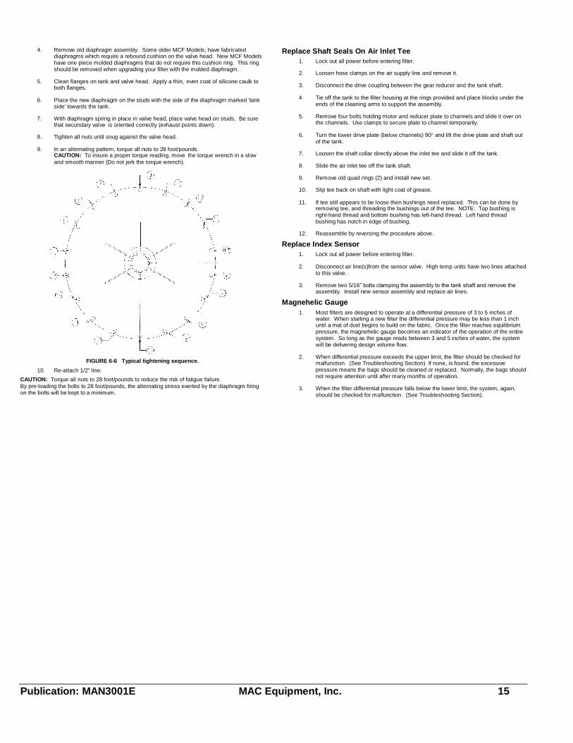
4. Remove old diaphragm assembly. Some older MCF Models, have fabricateddiaphragms which require a rebound cushion on the valve head. New MCF Modelshave one piece molded diaphragms that do not require this cushion ring. This ringshould be removed when upgrading your filter with the molded diaphragm.
5. Clean flanges on tank and valve head. Apply a thin, even coat of silicone caulk toboth flanges.
6. Place the new diaphragm on the studs with the side of the diaphragm marked 'tankside' towards the tank.
7. With diaphragm spring in place in valve head, place valve head on studs. Be surethat secondary valve is oriented correctly (exhaust points down).
8. Tighten all nuts until snug against the valve head.
9. In an alternating pattern, torque all nuts to 28 foot/pounds.CAUTION: To insure a proper torque reading, move the torque wrench in a slowand smooth manner (Do not jerk the torque wrench).
FIGURE 6-6 Typical tightening sequence.
10. Re-attach 1/2" line.
CAUTION: Torque all nuts to 28 foot/pounds to reduce the risk of fatigue failure.By pre-loading the bolts to 28 foot/pounds, the alternating stress exerted by the diaphragm firingon the bolts will be kept to a minimum.
Replace Shaft Seals On Air Inlet Tee1. Lock out all power before entering filter.
2. Loosen hose clamps on the air supply line and remove it.
3. Disconnect the drive coupling between the gear reducer and the tank shaft.
4. Tie off the tank to the filter housing at the rings provided and place blocks under theends of the cleaning arms to support the assembly.
5. Remove four bolts holding motor and reducer plate to channels and slide it over onthe channels. Use clamps to secure plate to channel temporarily.
6. Turn the lower drive plate (below channels) 90 and lift the drive plate and shaft outof the tank.
7. Loosen the shaft collar directly above the inlet tee and slide it off the tank.
8. Slide the air inlet tee off the tank shaft.
9. Remove old quad rings (2) and install new set.
10. Slip tee back on shaft with light coat of grease.
11. If tee still appears to be loose then bushings need replaced. This can be done byremoving tee, and threading the bushings out of the tee. NOTE: Top bushing isright-hand thread and bottom bushing has left-hand thread. Left hand threadbushing has notch in edge of bushing.
12. Reassemble by reversing the procedure above.
Replace Index Sensor1. Lock out all power before entering filter.
2. Disconnect air line(s)from the sensor valve. High temp units have two lines attachedto this valve.
3. Remove two 5/16� bolts clamping the assembly to the tank shaft and remove theassembly. Install new sensor assembly and replace air lines.
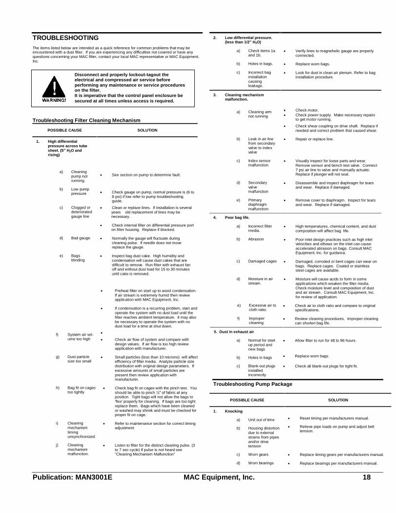
Magnehelic Gauge1. Most filters are designed to operate at a differential pressure of 3 to 5 inches of
water. When starting a new filter the differential pressure may be less than 1 inchuntil a mat of dust begins to build on the fabric. Once the filter reaches equilibriumpressure, the magnehelic gauge becomes an indicator of the operation of the entiresystem. So long as the gauge reads between 3 and 5 inches of water, the systemwill be delivering design volume flow.
2. When differential pressure exceeds the upper limit, the filter should be checked formalfunction. (See Troubleshooting Section) If none, is found, the excessivepressure means the bags should be cleaned or replaced. Normally, the bags shouldnot require attention until after many months of operation.
3. When the filter differential pressure falls below the lower limit, the system, again,should be checked for malfunction. (See Troubleshooting Section).
Publication: MAN3001E MAC Equipment, Inc. 16
Publication: MAN3001E MAC Equipment, Inc. 17
Publication: MAN3001E MAC Equipment, Inc. 18
TROUBLESHOOTINGThe items listed below are intended as a quick reference for common problems that may beencountered with a dust filter. If you are experiencing any difficulties not covered or have anyquestions concerning your MAC filter, contact your local MAC representative or MAC Equipment,Inc.
Troubleshooting Filter Cleaning Mechanism
POSSIBLE CAUSE SOLUTION
1. High differentialpressure across tubesheet. (5� H2O andrising)
a) Cleaningpump notrunning.
See section on pump to determine fault.
b) Low pumppressure Check gauge on pump, normal pressure is (6 to
8 psi) if low refer to pump troubleshootingguide.
c) Clogged ordeterioratedgauge line
Clean or replace lines. If installation is severalyears old replacement of lines may benecessary.
Check internal filter on differential pressure porton filter housing. Replace if blocked.
d) Bad gauge Normally the gauge will fluctuate duringcleaning pulse. If needle does not movereplace the gauge.
e) Bagsblinding
Inspect bag dust cake. High humidity andcondensation will cause dust cakes that aredifficult to remove. Run filter with exhaust fanoff and without dust load for 15 to 30 minutesuntil cake is removed.
Preheat filter on start up to avoid condensation.If air stream is extremely humid then reviewapplication with MAC Equipment, Inc.
If condensation is a recurring problem, start andoperate the system with no dust load until thefilter reaches ambient temperature. It may alsobe necessary to operate the system with nodust load for a time at shut down.
f) System air vol-ume too high
Check air flow of system and compare withdesign values. If air flow is too high reviewapplication with manufacturer.
g) Dust particlesize too small
Small particles (less than 10 microns) will affectefficiency of filter media. Analyze particle sizedistribution with original design parameters. Ifexcessive amounts of small particles arepresent then review application withmanufacturer.
h) Bag fit on cagestoo tightly
Check bag fit on cages with the pinch test. Youshould be able to pinch ½" of fabric at anyposition. Tight bags will not allow the bags to'flex' properly for cleaning. If bags are too tightreplace them. Bags which have been cleanedor washed may shrink and must be checked forproper fit on cage.
i) Cleaningmechanismtimingunsynchronized
Refer to maintenance section for correct timingadjustment
j) Cleaningmechanismmalfunction.
Listen to filter for the distinct cleaning pulse. (3to 7 sec cycle) If pulse is not heard see"Cleaning Mechanism Malfunction"
2. Low differential pressure.(less than 1/2� H2O)
a) Check items 1aand 1b.
Verify lines to magnehelic gauge are properlyconnected.
b) Holes in bags. Replace worn bags.
c) Incorrect baginstallationcausingleakage.
Look for dust in clean air plenum. Refer to baginstallation procedure.
3. Cleaning mechanismmalfunction.
a) Cleaning armnot running
Check motor. Check power supply. Make necessary repairs
to get motor running.
Check shear coupling on drive shaft. Replace ifneeded and correct problem that caused shear.
b) Leak in air linefrom secondaryvalve to indexvalve
Repair or replace line.
c) Index sensormalfunction
Visually inspect for loose parts and wear.Remove sensor and bench test valve. Connect7 psi air line to valve and manually actuate.Replace if plunger will not seal.
d) Secondaryvalvemalfunction
Disassemble and inspect diaphragm for tearsand wear. Replace if damaged.
e) Primarydiaphragmmalfunction.
Remove cover to diaphragm. Inspect for tearsand wear. Replace if damaged.
4. Poor bag life.
a) Incorrect filtermedia.
High temperatures, chemical content, and dustcomposition will affect bag life.
b) Abrasion Poor inlet design practices such as high inletvelocities and elbows on the inlet can causeaccelerated abrasion on bags. Consult MACEquipment, Inc. for guidance.
c) Damaged cages Damaged, corroded or bent cages can wear onbags. Replace cages. Coated or stainlesssteel cages are available.
d) Moisture in airstream.
Moisture will cause acids to form in someapplications which weaken the filter media.Check moisture level and composition of dustand air stream. Consult MAC Equipment, Inc.for review of application.
e) Excessive air tocloth ratio.
Check air to cloth ratio and compare to originalspecifications.
f) Impropercleaning.
Review cleaning procedures. Improper cleaningcan shorten bag life.
5. Dust in exhaust air
a) Normal for startup period andnew bags
Allow filter to run for 48 to 96 hours.
b) Holes in bags Replace worn bags
c) Blank-out plugsinstalledincorrectly
Check all blank-out plugs for tight fit.
Troubleshooting Pump Package
POSSIBLE CAUSE SOLUTION
1. Knocking
a) Unit out of time Reset timing per manufacturers manual.
b) Housing distortiondue to externalstrains from pipesand/or drivetension
Relieve pipe loads on pump and adjust belttension.
c) Worn gears Replace timing gears per manufacturers manual.
d) Worn bearings Replace bearings per manufacturers manual.
Disconnect and properly lockout-tagout theelectrical and compressed air service beforeperforming any maintenance or service procedureson the filter.It is imperative that the control panel enclosure besecured at all times unless access is required.
Publication: MAN3001E MAC Equipment, Inc. 19
e) Worn bearing fit Replace bearing and/or head plate permanufactures manual.
2. Excessive temperature in blo-wer.
a) Too much oil ingear case or drivecover
Reduce oil level to recommended levels.
b) Clogged filter ormuffler
Remove clog or replace component.
c) Worn impellerclearances
Restore clearances per manufactures recom-mendations.
3. Impeller end or tip drag
a) Incorrect clear-ances
Restore clearances per manufacturers recom-mendations.
b) Case or framedistortion
Relieve pipe loads on pump and adjust belttension.
c) Excessive opera-tion pressure
If all other aspects of the filter system are ok thenreduce drive speed to provide 7 psi max pressure.
4. Lack of air volume
a) Slipping belts Correct belt tension
b) Worn clearances Restore clearances per manufactures recom-mendations.
c) Leak in system Check for leaks in pipe lines and connection frompump to cleaning mechanism. Repair as needed.
5. Excessive bearing or gearwear
a) Improper lubri-cation
Correct oil level and follow lubrication schedule.
b) Worn filter Replace filter
6. Loss of oil
a) Vents plugged Check and replace vents in headplate, gear caseor drive cover
b) Worn seals Check for leakage around head plate and gearcase. Replace leaking seals.
The above is intended as a quick reference for common problems that may be encounteredwith a dust filter. If you are experiencing any difficulties not covered above or have anyquestions concerning your MAC filter, contact your local MAC representative or the MACEquipment Service Center at 1-888-821-2476.
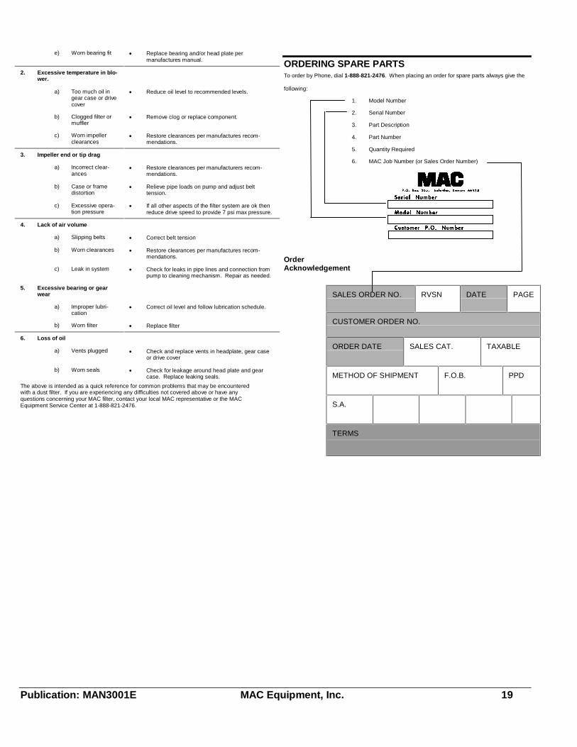
ORDERING SPARE PARTSTo order by Phone, dial 1-888-821-2476. When placing an order for spare parts always give the
following:
1. Model Number
2. Serial Number
3. Part Description
4. Part Number
5. Quantity Required
6. MAC Job Number (or Sales Order Number)
OrderAcknowledgement
SALES ORDER NO. RVSN DATE PAGE
CUSTOMER ORDER NO.
ORDER DATE SALES CAT. TAXABLE
METHOD OF SHIPMENT F.O.B. PPD
S.A.
TERMS

Publication: MAN3001E MAC Equipment, Inc. 20
Model Designations
96MCF153-140
Unit supplied with 140 BagsUnit capable of handling153 bagsFilter StyleLength of bags
Cleaning Mechanism
Figure 9-1 Typical Cleaning Mechanism
Cleaning Mechanism Spare Parts List
Item No. Part No. Description
4 307262 Rubber Sleeve
� 307246 Coupling 1-1/4� Bore
� 307254 Coupling 1-3/8� Bore
� 307122 Coupling 1� Bore
� 307033 Coupling 5/8� Bore
7 149217 Top Shaft Bearing 1-3/8� (4) Bolt Flange
9 & 10 415670 Quad Rings & Bushings
13 628710 10� Diaphragm (MCF 112,153, 255, 416)
� 628720 12� Diaphragm (MCF 361, 494, 572)
14 122270 10� Diaphragm Spring (MCF 112,153. 255, 416)
� 122289 12� Diaphragm Spring (MCF 361, 494, 572)
15 473049 Inlet Tee Assembly
16 314668 Secondary Diaphragm Valve
17 413226 Replacement Tip, Shaft, Spring, & Chain Link
-- 395780 Replacement Spring
18 330353 Bottom Shaft Bearing 1-7/16� (4) Bolt Flange
18 308535 Bottom Shaft Bearing 1-1/4� (4) Bolt Flange (MCF112)
19 402069 Index Sensor
24 424732 Timing Sprocket (MCF 112)
� 409924 Timing Sprocket (MCF 153-255)
� 409925 Timing Sprocket (MCF 361)
� 409926 Timing Sprocket (MCF416-572)
-- 119156 Cleaning Arm Nozzle
-- 122998 Blank-off Plug
Top Removal Bags (5" diameter)
Bag Length 16 Oz. Dacron 14 Oz. Polypropylene
96� 119849 119881
120� 119822 119873
144� 118915 119857
Top Removal Cages (5" diameter)
Galvanized Cage Length and Part Number
Filter Style 96� 120� 144�
MCF/MPH 105473 105481 105490
Top Removal Bags (6.2" diameter)
Bag Length 16 Oz. Dacron 14 Oz. Polypropylene
96� 101451 101524
120� 101443 101516
144� 101435 101508
Top Removal Cages (6.2" diameter)
Galvanized Cage Length and Part Number
Filter Style 96� 120� 144�
MCF/MPH 105350 105341 105333

Publication: MAN3001E MAC Equipment, Inc. 21
Miscellaneous Spare Parts
ItemNo.
Part No. Description
-- 415672 Aluminum 36 x 36 Panel w/ Gasket & Bolts
-- 103241 PVC 3/8� x 1� Bolts for Explosion Vent
-- 111090 Magnehelic Gauge 0-15� WC